JP6573861B2 - Door impact beam - Google Patents
Door impact beam Download PDFInfo
- Publication number
- JP6573861B2 JP6573861B2 JP2016193949A JP2016193949A JP6573861B2 JP 6573861 B2 JP6573861 B2 JP 6573861B2 JP 2016193949 A JP2016193949 A JP 2016193949A JP 2016193949 A JP2016193949 A JP 2016193949A JP 6573861 B2 JP6573861 B2 JP 6573861B2
- Authority
- JP
- Japan
- Prior art keywords
- top plate
- longitudinal direction
- pair
- vertical wall
- door
- Prior art date
- Legal status (The legal status is an assumption and is not a legal conclusion. Google has not performed a legal analysis and makes no representation as to the accuracy of the status listed.)
- Active
Links
Images


Classifications
-
- B—PERFORMING OPERATIONS; TRANSPORTING
- B60—VEHICLES IN GENERAL
- B60J—WINDOWS, WINDSCREENS, NON-FIXED ROOFS, DOORS, OR SIMILAR DEVICES FOR VEHICLES; REMOVABLE EXTERNAL PROTECTIVE COVERINGS SPECIALLY ADAPTED FOR VEHICLES
- B60J5/00—Doors
Description
本発明は、自動車のドア内部に補強部材として配置されるドアインパクトビームに関する。 The present invention relates to a door impact beam disposed as a reinforcing member inside a door of an automobile.
従来、自動車の側面衝突時の安全性を向上させるため、ドア内部に補強部材としてドアインパクトビーム(DIB;Door Impact Beam)を装着することが知られている。このドアインパクトビームは、例えば長尺なパイプ材や押出し角材などからなるものであり、車体の前後方向に沿った状態でドアのアウターパネルとインナーパネルとの間に配置されるものである。このようなドアインパクトビームの構造が下記特許文献1〜3に開示されている。
Conventionally, in order to improve safety at the time of a side collision of an automobile, it is known to install a door impact beam (DIB; Door Impact Beam) as a reinforcing member inside the door. This door impact beam is made of, for example, a long pipe material or extruded square material, and is disposed between the outer panel and the inner panel of the door in a state along the front-rear direction of the vehicle body. The structure of such a door impact beam is disclosed in the following
下記特許文献1には、ドアインパクトビームとして用いられる長尺な部材であって、断面視ハット形状に形成されたものが開示されている。下記特許文献2には、断面視M字型形状に形成されたドアインパクトビームの構造が開示されている。下記特許文献3には、長尺な板材からなるドアインパクトビームであって、板厚方向において上下に突出するビード部が形成されたものが開示されている。
The following
ドアインパクトビームにおいては、車体の重量増加を抑制しつつドア部分を確実に補強するという高度な性能が要求されるところ、上記特許文献1〜3に開示される従来のドアインパクトビームは、このような性能を十分に備えていないという問題があった。 The door impact beam is required to have a high performance of securely reinforcing the door portion while suppressing an increase in the weight of the vehicle body. There is a problem that it does not have sufficient performance.
上記特許文献1のドアインパクトビームは、ハット形状の天板部を平板形状に形成すると共に、当該天板部を複数のリブの設置により補強するものである。この構造では、リブの設置によりドアビームの重量増加を招くという問題がある。またこのリブは、ハット形状の中空部内において天板部と反対側の部位まで延びるように設置されているが、このリブは、圧壊時に容易に横倒れしてしまう。その結果、天板部において十分な補強効果が得られないという問題もある。
The door impact beam of
上記特許文献2のドアインパクトビームは、板材を断面視M字型形状に屈曲させたものであり、直辺状の明確な縦壁を有するハット断面からなるものに比べて強度面で劣る。また上記特許文献3のドアインパクトビームでは、板厚方向において上下に突出するビード部を設けることにより線長が長くなるため、ドアビームの重量増加を避けられない。 The door impact beam of Patent Document 2 is obtained by bending a plate material into an M-shaped shape in cross-sectional view, and is inferior in strength as compared to a hat cross section having a straight vertical wall. Moreover, in the door impact beam of the said patent document 3, since the line length becomes long by providing the bead part which protrudes up and down in a plate | board thickness direction, the weight increase of a door beam cannot be avoided.
本発明は、上記課題に鑑みてなされたものであり、その目的は、自動車の側面衝突時の衝撃荷重に対する強度と重量のバランスに優れたドアインパクトビームを提供することである。 The present invention has been made in view of the above problems, and an object of the present invention is to provide a door impact beam having an excellent balance between strength and weight against an impact load at the time of a side collision of an automobile.
本発明の一局面に係るドアインパクトビームは、一方向に長い形状のビーム本体部と、前記ビーム本体部の両端に設けられ、ドア内部に取り付けられる取付部と、を備えている。前記ビーム本体部の長手方向の少なくとも一部は、前記長手方向に垂直な断面内において、前記長手方向に垂直な幅方向に互いに対向する一対の縦壁部と、前記一対の縦壁部の上端同士を繋ぐ天板部と、を有している。前記天板部の前記長手方向の少なくとも一部には、前記長手方向及び前記幅方向に垂直な高さ方向に突出した形状を有し且つ前記長手方向に延びると共に前記幅方向に並ぶ複数の凸条部を含み、前記高さ方向の曲げに対する中立面よりも前記天板部側の領域において凹凸する形状の波形部が形成されている。前記複数の凸条部は、互いに離間して形成された一対の第1の凸条部と、前記一対の第1の凸条部の間に形成された第2の凸条部と、を含んでいる。前記第1の凸条部は、前記第2の凸条部の幅よりも小さい幅を有している。 A door impact beam according to an aspect of the present invention includes a beam main body portion that is long in one direction, and attachment portions that are provided at both ends of the beam main body portion and are attached to the inside of the door. At least a part of the beam body in the longitudinal direction includes a pair of vertical wall portions facing each other in a width direction perpendicular to the longitudinal direction in a cross section perpendicular to the longitudinal direction, and upper ends of the pair of vertical wall portions. And a top plate part that connects the two. At least a part of the top plate portion in the longitudinal direction has a shape protruding in the height direction perpendicular to the longitudinal direction and the width direction, and extends in the longitudinal direction and is arranged in the width direction. A corrugated portion having a shape that includes a strip and is uneven in a region closer to the top plate than a neutral plane for bending in the height direction is formed. The plurality of ridges include a pair of first ridges formed apart from each other, and a second ridge formed between the pair of first ridges. It is out. The first ridge has a width smaller than the width of the second ridge.
上記ドアインパクトビームでは、ビーム本体部の長手方向の少なくとも一部が、一対の縦壁部とその上端同士を繋ぐ天板部とを有する形状(ハット形状)に形成されることにより、ビーム本体部の剛性が高められている。しかも、このハット形状の天部に相当する位置の天板部が波形に形成されている。この天板部は、ビーム本体部の断面内における中立面から離れた部分であり、側面衝突時の衝撃荷重によって大きな応力が生じる部分である。従って、この天板部が波形に形成されることにより、衝撃荷重に対する強度が効果的に向上している。 In the door impact beam, at least a part of the beam main body in the longitudinal direction is formed in a shape (hat shape) having a pair of vertical wall portions and a top plate portion connecting the upper ends of the beam main body portions, thereby the beam main body portion. The rigidity is improved. In addition, a top plate portion at a position corresponding to the hat-shaped top portion is formed in a waveform. The top plate portion is a portion away from the neutral plane in the cross section of the beam main body portion, and is a portion where a large stress is generated by an impact load at the time of a side collision. Therefore, the strength against the impact load is effectively improved by forming the top plate portion in a waveform.
さらに、この波形部は、中立面よりも天板部側の領域内に収まっている。これにより、側面衝突によりドアインパクトビームに対して曲げモーメントが加わった時に、波形部に対して圧縮応力又は引張応力のいずれか一方のみを生じさせることができる。この点においても、衝撃荷重に対する強度が飛躍的に向上している。しかも、波形部を天板部側の領域内に収めることにより、波形部の線長が長くなり過ぎず、ドアビームの重量増加を抑制することもできる。従って、本発明によれば、側面衝突時の衝撃荷重に対する強度と重量のバランスに優れたドアビーム構造を得ることができる。また上記構成によれば、天板部と縦壁部とが繋がる部分を補強することができるため、より強度に優れたドアインパクトビームを提供することができる。 Furthermore, this corrugated part is contained in the area | region of the top-plate part side rather than a neutral surface. Thereby, when a bending moment is applied to the door impact beam due to the side collision, only one of the compressive stress and the tensile stress can be generated on the corrugated portion. Also in this respect, the strength against the impact load is dramatically improved. Moreover, by accommodating the corrugated portion in the region on the top plate portion side, the line length of the corrugated portion does not become too long, and an increase in the weight of the door beam can be suppressed. Therefore, according to this invention, the door beam structure excellent in the balance of the intensity | strength with respect to the impact load at the time of a side collision, and a weight can be obtained. Moreover, according to the said structure, since the part which a top plate part and a vertical wall part connect can be reinforced, the door impact beam excellent in intensity | strength can be provided.
上記ドアインパクトビームにおいて「凸条部が長手方向に延びる」とは、凸条部が長手方向に平行に延びる形態だけでなく、凸条部が長手方向に対して傾斜した状態で長手方向に沿って延びる形態も含む。また、凸条部が長手方向に沿って直線状に延びる形態だけでなく、長手方向に沿って曲がりながら延びる形態も含む。 In the above-mentioned door impact beam, “the ridges extend in the longitudinal direction” means not only the form in which the ridges extend in parallel to the longitudinal direction, but also the longitudinal direction with the projections inclined with respect to the longitudinal direction. It includes a form that extends. In addition to the form in which the ridges extend linearly along the longitudinal direction, a form that extends while bending along the longitudinal direction is also included.
本発明の他の局面に係るドアインパクトビームは、一方向に長い形状のビーム本体部と、前記ビーム本体部の両端に設けられ、ドア内部に取り付けられる取付部と、を備えている。前記ビーム本体部の長手方向の少なくとも一部は、前記長手方向に垂直な断面内において、前記長手方向に垂直な幅方向に互いに対向する一対の縦壁部と、前記一対の縦壁部の上端同士を繋ぐ天板部と、を有している。前記天板部の前記長手方向の少なくとも一部には、前記長手方向及び前記幅方向に垂直な高さ方向に突出した形状を有し且つ前記長手方向に延びると共に前記幅方向に並ぶ複数の凸条部を含み、前記高さ方向の曲げに対する中立面よりも前記天板部側の領域において凹凸する形状の波形部が形成されている。前記複数の凸条部は、互いに離間して形成された一対の第1の凸条部と、前記一対の第1の凸条部の間に形成された第2の凸条部と、を含んでいる。前記第2の凸条部は、前記一対の第1の凸条部よりも小さい前記高さ方向の寸法を有している。 A door impact beam according to another aspect of the present invention includes a beam body portion that is long in one direction, and attachment portions that are provided at both ends of the beam body portion and are attached to the inside of the door. At least a part of the beam body in the longitudinal direction includes a pair of vertical wall portions facing each other in a width direction perpendicular to the longitudinal direction in a cross section perpendicular to the longitudinal direction, and upper ends of the pair of vertical wall portions. And a top plate part that connects the two. At least a part of the top plate portion in the longitudinal direction has a shape protruding in the height direction perpendicular to the longitudinal direction and the width direction, and extends in the longitudinal direction and is arranged in the width direction. A corrugated portion having a shape that includes a strip and is uneven in a region closer to the top plate than a neutral plane for bending in the height direction is formed. The plurality of ridges include a pair of first ridges formed apart from each other, and a second ridge formed between the pair of first ridges. Idei Ru. The second convex portions that have the height dimension smaller than the pair of first convex portions.
この構成によれば、側面衝突時の衝撃荷重を1つの凸条部だけではなく複数の凸条部(第1の凸条部)により受けることができる。このため、衝撃荷重を部材の内部において分散させることが可能になる。これにより、側面衝突によるドアインパクトビームの破損をより確実に防ぐことができる。 According to this structure, the impact load at the time of a side collision can be received not only by one protrusion part but by several protrusion part (1st protrusion part). For this reason, it is possible to disperse the impact load within the member. Thereby, damage to the door impact beam due to a side collision can be prevented more reliably.
本発明のさらに他の局面に係るドアインパクトビームは、一方向に長い形状のビーム本体部と、前記ビーム本体部の両端に設けられ、ドア内部に取り付けられる取付部と、を備えている。前記ビーム本体部の長手方向の少なくとも一部は、前記長手方向に垂直な断面内において、前記長手方向に垂直な幅方向に互いに対向する一対の縦壁部と、前記一対の縦壁部の上端同士を繋ぐ天板部と、を有している。前記天板部の前記長手方向の少なくとも一部には、前記長手方向及び前記幅方向に垂直な高さ方向に突出した形状を有し且つ前記長手方向に延びると共に前記幅方向に並ぶ複数の凸条部を含み、前記高さ方向の曲げに対する中立面よりも前記天板部側の領域において凹凸する形状の波形部が形成されている。前記複数の凸条部は、互いに離間して形成された一対の第1の凸条部と、前記一対の第1の凸条部の間に形成された第2の凸条部と、を含んでいる。前記第2の凸条部は、前記一対の第1の凸条部よりも大きい前記高さ方向の寸法を有している。 A door impact beam according to still another aspect of the present invention includes a beam body portion that is long in one direction, and attachment portions that are provided at both ends of the beam body portion and are attached to the inside of the door. At least a part of the beam body in the longitudinal direction includes a pair of vertical wall portions facing each other in a width direction perpendicular to the longitudinal direction in a cross section perpendicular to the longitudinal direction, and upper ends of the pair of vertical wall portions. And a top plate part that connects the two. At least a part of the top plate portion in the longitudinal direction has a shape protruding in the height direction perpendicular to the longitudinal direction and the width direction, and extends in the longitudinal direction and is arranged in the width direction. A corrugated portion having a shape that includes a strip and is uneven in a region closer to the top plate than a neutral plane for bending in the height direction is formed. The plurality of ridges include a pair of first ridges formed apart from each other, and a second ridge formed between the pair of first ridges. Idei Ru. The second convex portions that have a pair of dimensions of the first larger the height direction than the convex portion.
この構成によれば、第2の凸条部が第1の凸条部よりも低く形成されたものに比べて、ドアインパクトビームの静的強度をより向上させることが可能になる。 According to this configuration, it is possible to further improve the static strength of the door impact beam as compared with the case where the second ridge is formed lower than the first ridge.
上記ドアインパクトビームにおいて、前記天板部が前記縦壁部よりも厚く形成されていてもよい。 In the door impact beam, the top plate portion may be formed thicker than the vertical wall portion.
この構成によれば、天板部においてビーム本体部を部分増厚することにより、部材全体を増厚したものに比べて、重量増加をより小さくすることができる。これにより、衝撃荷重に対する強度を維持しつつ、より軽量化されたドアインパクトビームを得ることができる。また部材全体を増厚する場合に比べて、コスト削減を図ることもできる。 According to this configuration, by increasing the thickness of the beam main body portion in the top plate portion, the weight increase can be reduced as compared with the case where the entire member is increased in thickness. As a result, a lighter door impact beam can be obtained while maintaining the strength against the impact load. Further, the cost can be reduced as compared with the case where the entire member is thickened.
上記ドアインパクトビームにおいて、前記ビーム本体部は、前記高さ方向において前記中立面に対して前記天板部と反対側において前記縦壁部に設けられ、前記長手方向に延びると共に前記幅方向外側に広がる形状のフランジ部を有していてもよい。 In the door impact beam, the beam main body portion is provided on the vertical wall portion on the side opposite to the top plate portion with respect to the neutral surface in the height direction, extends in the longitudinal direction, and extends outward in the width direction. You may have a flange part of the shape which spreads.
この構成によれば、高さ方向において中立面を天板部からより遠ざけることができる。このため、中立面から天板部までの高さ距離がより長くなり、衝撃荷重により天板部に生じる応力もより大きくなることから、波形部の形成による強度向上の効果がより顕著になる。 According to this configuration, the neutral surface can be further away from the top plate in the height direction. For this reason, the height distance from the neutral surface to the top plate portion becomes longer, and the stress generated in the top plate portion by the impact load becomes larger, so the effect of improving the strength by forming the corrugated portion becomes more remarkable. .
上記ドアインパクトビームでは、前記フランジ部において前記縦壁部と反対側の端部が前記天板部側に折り返されていてもよい。 In the said door impact beam, the edge part on the opposite side to the said vertical wall part in the said flange part may be return | folded by the said top-plate part side.
この構成によれば、ドアインパクトビームの幅が増加するのを抑制しつつ、中立面の高さ位置を天板部からさらに遠ざけることができる。 According to this configuration, the height position of the neutral surface can be further away from the top plate portion while suppressing an increase in the width of the door impact beam.
以上の説明から明らかなように、本発明によれば、自動車の側面衝突時の衝撃荷重に対する強度と重量のバランスに優れたドアインパクトビームを提供することができる。 As is apparent from the above description, according to the present invention, it is possible to provide a door impact beam having an excellent balance between strength and weight against impact load at the time of a side collision of an automobile.
以下、図面に基づいて、本発明の実施形態につき詳細に説明する。 Hereinafter, embodiments of the present invention will be described in detail with reference to the drawings.
(実施形態1)
[ドアインパクトビームの構造]
まず、本発明の実施形態1に係るドアインパクトビーム1の構造について、図1〜図3を参照して説明する。図1は、ドアインパクトビーム1が自動車のドア100に配置された様子を概念的に示している。図2は、ドアインパクトビーム1の上面側から見た全体構造を示す斜視図である。図3は、図2中の線分III−IIIに沿ったドアインパクトビーム1の断面構造を示している。
(Embodiment 1)
[Door impact beam structure]
First, the structure of the
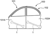
ドアインパクトビーム1は、自動車の側面衝突時の衝撃荷重Pに対する補強部材としてドア100の内部に装着されるものであり、長手方向に延びる長尺な形状を有している。図1に示すように、ドア100は、フロントドア101と、リアドア102と、を有している。ドアインパクトビーム1は、前端が後端よりも高くなるように水平方向に対して傾斜した姿勢で、フロントドア101及びリアドア102の各々の内部に装着されている。より具体的には、ドアインパクトビーム1は、ドア100のインナーパネルとアウターパネル101A,102Aとの間に配置されており、天板部21(図2)をアウターパネル101A,102A側に向けた姿勢で装着される。なお、ドアインパクトビーム1は、水平方向に沿った姿勢で装着されてもよい。
The
ドアインパクトビーム1は、例えば高張力鋼(ハイテン)からなる単一の板材をホットスタンプ(熱間プレス)によってプレス成形することにより形成されている。なお、ドアインパクトビーム1に用いられる材質はハイテンに限定されず、種々の金属材料を採用することが可能である。
The
図2に示すように、ドアインパクトビーム1は、一方向に長い形状のビーム本体部16と、ビーム本体部16の長手方向の両端に設けられた一対の取付部(第1の取付部11及び第2の取付部12)と、を備えている。ドアインパクトビーム1は、長手方向の中心に対して対称な形状を有している。本実施形態では、ビーム本体部16と第1及び第2の取付部11,12とは単一の鋼板として一体形成されているがこれに限定されず、互いに別体として形成されていてもよい。
As shown in FIG. 2, the
第1及び第2の取付部11,12は、ドア内部に取り付けられる部分であり、ドア内部に設けられた所定の被取付部(不図示)に対して取付可能な形状に形成されている。図2に示すように、本実施形態では、第1及び第2の取付部11,12は、平坦面11A,12Aを各々有しており、ビーム本体部16よりも幅広である薄い平板形状に形成されている。このような平板形状を採用することで、ドア内部に対して取り付け易い構造とすることができる。なお、第1及び第2の取付部11,12の形状はこれに限定されず、ドア内部の被取付部の形状に応じて適宜変更することが可能である。また第1及び第2の取付部11,12は、図1に示すように各々同じ形状に形成されていてもよいがこれに限定されず、各々異なる形状に形成されていてもよい。
The 1st and 2nd attaching
第1及び第2の取付部11,12は、例えばボルトやナットなどの締結部材を用いて又は溶接によりドア内部に固定される。これにより、第1及び第2の取付部11,12において両点支持した状態でドアインパクトビーム1をドア内部に装着することができる。このため、側面衝突時においてドアインパクトビーム1が衝撃荷重Pを受けたとき、ビーム本体部16に対して主に曲げモーメントが加わる。また第1及び第2の取付部11,12は、その一方が車体の前方側に位置し、他方が後方側に位置した状態となる。
The first and
ビーム本体部16は、側面衝突時に主に衝撃荷重Pを受ける部分であり、長手方向に延びる長尺な形状を有している。ビーム本体部16は、ビーム中央部14と、ビーム中央部14の長手方向の両端に設けられた一対のビーム側部(第1のビーム側部13及び第2のビーム側部15)と、を有しており、これらが長手方向に連なることにより構成されている。
The beam
ビーム中央部14は、平面視長方形状の上面14Aを有しており、長手方向に略一定の高さを有している。第1及び第2のビーム側部13,15は、ビーム中央部14の両端に各々繋がると共に、長手方向外側に向かって下り勾配に形成された上面13A,15Aを各々有している。そして、第1及び第2のビーム側部13,15は、長手方向外側の端部において第1及び第2の取付部11,12に各々繋がっている。
The
このため、図2に示すように、ビーム中央部14は、第1及び第2の取付部11,12に対して高さ方向上向きに張り出した状態となっている。従って、上面14Aが車体のアウターパネル側に向いた姿勢でドアインパクトビーム1が装着された時、当該上面14Aに対して衝撃荷重Pが主に加わる。つまり、ビーム中央部14の上面14Aが衝撃荷重Pの主な受け面となる。
For this reason, as shown in FIG. 2, the beam
ビーム本体部16は、上面13A〜15Aを含む平面視長方形状の天板部21と、天板部21の幅方向の端部に繋がれ、当該端部から天板部21に対して略直角を成して下向きに垂下する一対の縦壁部22,23と、縦壁部22,23の下端から幅方向外側に張り出した一対のフランジ部24,25と、を備えている。
The
図2に示すように、天板部21は、上面14Aと上面13Aとが繋がる曲面状の第1アール部16A及び上面14Aと上面15Aとが繋がる曲面状の第2アール部16Bにおいて、下向きに折り曲げられた板形状を呈している。また一対のフランジ部24,25は、ビーム本体部16全体に亘って長手方向に延びている。一対のフランジ部24,25は、長手方向の両端を有し、当該両端が第1及び第2の取付部11,12に各々繋がっている。
As shown in FIG. 2, the
なお、図2では、天板部21の幅方向の一端に繋がる一方の縦壁部22及びこれに設けられた一方のフランジ部24のみが示されているが、上述の通り、天板部21の他端にも縦壁部23(図3)が同様に繋がっており、且つ当該他方の縦壁部23の下端から幅方向外側に張り出した他方のフランジ部25(図3)が設けられている。これにより、ビーム本体部16は、互いに対向する一対の縦壁部(第1の縦壁部22及び第2の縦壁部23)と、これらを繋ぐ天板部21と、一対のフランジ部(第1のフランジ部24及び第2のフランジ部25)と、により断面視ハット形状を構成している。
In FIG. 2, only one
また本実施形態では、ビーム中央部14だけでなく、第1及び第2のビーム側部13,15も、天板部21と、一対の縦壁部22,23と、一対のフランジ部24,25と、を有する断面視ハット形状に形成されている。つまり本実施形態では、ビーム本体部16の長手方向全体が断面視ハット形状に形成されている。
In the present embodiment, not only the beam
図2に示すように、天板部21においてビーム中央部14の上面14Aを構成する部位は、平面視長方形の外形を有する波形部40と、波形部40の外周全体を取り囲む周辺部46と、を有している。波形部40は、天板部21を高さ方向に凹凸するように屈曲させた部位であり、周辺部46は平板形状に形成された部位である。上述のように、ビーム中央部14は衝撃荷重Pが主に加わる部分であるため、この波形部40を形成することにより、衝撃荷重Pに対する天板部21の強度を高めることができる。
As shown in FIG. 2, the portion constituting the
一方、天板部21において第1及び第2のビーム側部13,15の上面13A,15Aを構成する部位は、波形部が形成されておらず、平板形状に形成されている。つまり本実施形態では、天板部21の長手方向の一部(中央部)のみにおいて波形部40が形成されている。
On the other hand, in the
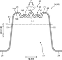
次に、ビーム本体部16の長手方向に垂直な断面構造について、図3を参照して説明する。図3は、図2中の線分III−IIIにおけるビーム中央部14の断面構造を示している。図3に示すように、ビーム中央部14は、長手方向に垂直な断面内において、高さ方向下向きに開口する開断面を有する。即ち、ビーム中央部14は、所謂ハット形状に形成されている。ビーム中央部14は、幅方向に互いに対向する一対の縦壁部22,23(第1及び第2の縦壁部22,23)と、当該第1及び第2の縦壁部22,23の上端22A,23A同士を繋ぐ天板部21と、当該第1及び第2の縦壁部22,23の下端22B,23Bから幅方向外側に広がる形状の一対のフランジ部(第1のフランジ部24及び第2のフランジ部25)と、を有する。第1及び第2のフランジ部24,25は、高さ方向において中立面31に対して天板部21と反対側において第1及び第2の縦壁部22,23に設けられている。ビーム中央部14は、一対の縦壁部22,23と、天板部21と、一対のフランジ部24,25と、によりハット形状を構成している。
Next, a cross-sectional structure perpendicular to the longitudinal direction of the beam
第1及び第2の縦壁部22,23は、天板部21の幅に相当する間隔を空けて互いに対向するように配置されており、天板部21の幅方向の両端に対して曲面状の稜部を成すように繋がっている。また第1及び第2のフランジ部24,25も、第1及び第2の縦壁部22,23の下端22B,23Bに対して曲面状に繋がっている。ビーム中央部14は、天板部21と第1及び第2の縦壁部22,23の内面側に空間S1が形成された中空構造となっている。また上述の通り、第1及び第2のビーム側部13,15も、ビーム中央部14と同様に断面視ハット形状に形成されているため、図3に示すような中空構造となっている。
The first and second
ドアインパクトビーム1では、天板部21側から長手方向の中央部に対して下向きに衝撃荷重Pが加わる場合において、中立面31よりも上側(上面側)で圧縮応力が生じ、中立面31よりも下側(下面側)で引張応力が生じるのに対し、圧縮応力も引張応力も生じない領域が存在する。この領域を図3に示す断面内において符号「31」で示し、これを「中立面31」と称している。図3に示すように、天板部21は、ビーム本体部16の断面内における中立面31よりも高さ方向上側に位置する部位である。
In the
天板部21は、高さ方向に凹凸する形状の波形部40と、その両側に設けられた一対の肩部44,45(第1及び第2の肩部44,45)と、を備えている。波形部40は、天板部21における幅方向の中央部を凹凸状に屈曲させた部分であり、図3に示すように幅方向に対称な形状を有している。より具体的には、波形部40において、上面14Aが凸状である部分において下面14Bが凹んでおり、上面14Aが凹んでいる部分において下面14Bが凸状になっている。
The
第1の肩部44は、波形部40の一端(図3中右端)に繋がると共に、第1の縦壁部22の上端22Aに繋がっている。第2の肩部45は、波形部40の他端(図3中左端)に繋がると共に、第2の縦壁部23の上端23Aに繋がっている。図2に示すように、第1及び第2の肩部44,45は、周辺部46における幅方向両側の部位にそれぞれ相当する。
The
波形部40は、高さ方向上向きに突出した形状を有する複数の凸条部41〜43により構成されている。複数の凸条部41〜43の各々は、長手方向に延びると共に当該長手方向に垂直な幅方向に並んで設けられている。また図3に示すように、波形部40は、中立面31よりも天板部21側の領域R1内に収まるように凹凸した形状となっている。つまり、波形部40は、図3に示す断面内において中立面31と重複(交差)せず、各凸条部41〜43の底部(図3中破線)が中立面31よりも距離L1だけ高さ方向上側に位置するように形成されている。
The
上記ドアインパクトビーム1では、図3に示すように、ビーム本体部16が断面視ハット形状に形成されることにより、剛性が高められている。ここで、ハット形状の天部に相当する位置にある天板部21は、ビーム本体部16の断面内における中立面31から高さ方向に離れた部分であり、衝撃荷重Pによって大きな圧縮応力が生じる部分である。この天板部21に波形部40が形成されることにより、衝撃荷重Pに対する強度が効果的に向上している。
In the
また波形部40は、中立面31よりも天板部21側の領域R1内に収まっている。これにより、衝撃荷重Pによりドアインパクトビーム1に対して曲げモーメントが加わった時に、波形部40に対して圧縮応力又は引張応力のいずれか一方のみを生じさせることができる。このため、衝撃荷重Pに対するドアビームの強度が飛躍的に向上している。しかも、波形部40は中立面31よりも高さ方向下側の領域までは形成されていないため、波形部40の線長が長くなり過ぎず、ドアビームの重量増加を抑制することもできる。このため、上記ドアインパクトビーム1は、強度と重量のバランスを損なうことなく、性能が向上したものとなっている。
Further, the
波形部40は、上述のように高さ方向上向きに突出する複数(本実施形態では3つ)の凸条部41〜43を含み、これらが幅方向に連続して並ぶことにより形成されている。本実施形態では、各凸条部41〜43の頂部が車体の外側に向いた姿勢でドアインパクトビーム1がドア100に装着される。
The
複数の凸条部41〜43は、天板部21の幅方向中央に形成された第2の凸条部41と、その両側に形成された一対の第1の凸条部42,43と、を含んでいる。図3に示すように、一対の第1の凸条部42,43は幅方向において互いに離間して形成されており、その間の位置に第2の凸条部41が形成されている。なお、本実施形態では、波形部40が3つの凸条部41〜43により構成される場合について説明したがこれに限定されず、第1の凸条部42,43よりも幅方向外側の位置にさらに別の凸条部が形成されていてもよい。
The plurality of
本実施形態では、第1の凸条部42,43と第2の凸条部41とは、各々同じ高さ方向の寸法を有している。また図3に示すように、第1の凸条部42,43は、第2の凸条部41の幅よりも小さい幅を有している。即ち、複数の凸条部41〜43は、天板部21と縦壁部22,23との接続部に対してより近い位置に形成されたものが小さい幅を有している。これにより、天板部21と縦壁部22,23との接続部における強度をより向上させることができる。
In this embodiment, the 1st protruding item |
ビーム中央部14は、天板部21において部分増厚されたものとなっている。即ち、ビーム中央部14において、天板部21は、第1及び第2の縦壁部22,23よりも厚く形成されている。より具体的には、波形部40の厚さT1が第1及び第2の縦壁部22,23の厚さT2よりも大きくなっており、第1及び第2の肩部44,45の厚さが第1及び第2の縦壁部22,23の厚さと同じになっている。つまり、ビーム中央部14は、波形部40のみにおいて部分増厚されている。
The
線長方向に沿って厚さの変化を説明すると、第1のフランジ部24、第1の縦壁部22及び第1の肩部44においては厚さT2が維持され、波形部40の開始部(図3中右端)から厚さが徐々に増大し、波形部40において増大した厚さT1が維持される。そして、波形部40の終了部(図3中左端)から厚さが徐々に減少し、第2の肩部45、第2の縦壁部23及び第2のフランジ部25において減少した厚さT2が維持される。
Explaining the change in thickness along the line length direction, the thickness T2 is maintained in the
このように、衝撃荷重Pにより大きな圧縮応力が生じる天板部21において波形部40を部分増厚することにより、ドアビームの強度を向上させることができる。また、第1及び第2の縦壁部22,23も波形部40と同様に増厚したもの(全体増厚したもの)と比べて、ドアビーム全体の重量増加を抑えることができる。
Thus, by partially thickening the
またビーム本体部16は、長手方向の少なくとも一部が部分増厚されていればよい。本実施形態では、長手方向の一部であるビーム中央部14のみが上述のように部分増厚されており、第1及び第2のビーム側部13,15は部分増厚されていない。即ち、第1及び第2のビーム側部13,15においては、天板部21と第1及び第2の縦壁部22,23とが同じ厚みで形成されている。
Moreover, the beam main-
[ドアインパクトビームの成形プロセス]
次に、ホットスタンプによる上記ドアインパクトビーム1の成形プロセスについて、図4及び図5を参照して説明する。
[Door impact beam forming process]
Next, a process for forming the
まず、ハイテンなどの鋼材からなる平板形状の被プレス部材60が準備される。そして、この被プレス部材60を型押しなどによって加工することにより、図4に示すように台形状に曲がった被プレス部61を幅方向の中央に形成する。そして、図4に示すように被プレス部材60を金型51,52間に配置した状態で、上金型51を下金型52に向かって下降させる。
First, a flat plate-shaped pressed
そして、被プレス部61の台形の高さがなくなるまで上金型51を下降させた時点でプレス成形が完了する。これにより、図5に示すように、上金型51の成形面51A及び下金型52の成形面55Aに沿った凹凸形状の波形部が被プレス部61に形成される。このプレス成形後の被プレス部61が図3に示した天板部21となる。その後、上金型51を上昇させ、プレス成形後の被プレス部材60(ドアインパクトビーム1)を金型から取り出す。
And press molding is completed when the upper metal mold | die 51 is lowered | hung until the height of the trapezoid of the to-
[作用効果]
次に、上記本実施形態に係るドアインパクトビーム1の特徴的な構成及びその作用効果について説明する。
[Function and effect]
Next, a characteristic configuration of the
図2に示すように、ドアインパクトビーム1は、一方向に長い形状のビーム本体部16と、ビーム本体部16の両端に設けられた取付部11,12と、を備えている。図3に示すように、ビーム本体部16は、長手方向に垂直な断面内において、長手方向に垂直な幅方向に互いに対向する一対の縦壁部22,23と、一対の縦壁部22,23の上端22A,23A同士を繋ぐ天板部21と、を有している。天板部21には、長手方向及び幅方向に垂直な高さ方向に突出した形状を有し且つ長手方向に延びると共に幅方向に並ぶ複数の凸条部41〜43を含み、高さ方向の曲げに対する中立面31よりも天板部21側の領域R1において凹凸する形状の波形部40が形成されている。
As shown in FIG. 2, the
ドアインパクトビーム1では、ビーム本体部16が一対の縦壁部22,23とその上端22A,23A同士を繋ぐ天板部21とを有するハット形状に形成されることにより、ビーム本体部16の剛性が高められている。しかも、このハット形状の天部に相当する位置の天板部21が波形に形成されている。この天板部21は、ビーム本体部16の断面内における中立面31から離れた部分であり、側面衝突時の衝撃荷重Pによって大きな応力が生じる部分である。従って、この天板部21が波形に形成されることにより、衝撃荷重Pに対する強度が効果的に向上している。
In the
さらに、波形部40は、中立面31よりも天板部21側の領域R1内に収まっている。これにより、側面衝突によりドアインパクトビーム1に対して曲げモーメントが加わった時に、波形部40に対して圧縮応力又は引張応力のいずれか一方のみを生じさせることができる。この点においても、衝撃荷重Pに対する強度が飛躍的に向上している。しかも、波形部40を天板部21側の領域R1内に収めることにより、波形部40の線長が長くなり過ぎず、ドアビームの重量増加を抑制することもできる。従って、側面衝突時の衝撃荷重Pに対する強度と重量のバランスに優れたドアビーム構造を得ることができる。
Further, the
上記ドアインパクトビーム1において、複数の凸条部41〜43は、互いに離間して形成された一対の第1の凸条部42,43と、一対の第1の凸条部42,43の間に形成された第2の凸条部41と、を含んでいる。第1の凸条部42,43は、第2の凸条部41の幅よりも小さい幅を有している。これにより、天板部21と縦壁部22,23とが繋がる部分を補強することができるため、より強度に優れたドアインパクトビーム1を得ることができる。
In the
上記ドアインパクトビーム1において、波形部40は縦壁部22,23よりも厚く形成されている。このように、天板部21において部分増厚することにより、部材全体を増厚したものに比べて、重量増加をより小さくすることができる。これにより、衝撃荷重Pに対する強度を維持しつつ、より軽量化されたドアインパクトビーム1を得ることができる。
In the
上記ドアインパクトビーム1において、ビーム本体部16は、高さ方向において中立面31に対して天板部21と反対側において縦壁部22,23に設けられ、長手方向に延びると共に幅方向外側に広がる形状のフランジ部24,25を有している。これにより、高さ方向において中立面31を天板部21からより遠ざけることができる。このため、中立面31から天板部21までの高さ距離L1がより長くなり、衝撃荷重Pにより天板部21に生じる圧縮応力もより小さくなることから、波形部40の形成による強度向上の効果がより顕著になる。
In the
(実施形態2)
次に、本発明の実施形態2に係るドアインパクトビームについて、図6を参照して説明する。実施形態2に係るドアインパクトビームは、基本的に上記実施形態1の場合と同様の構成を備えているが、第1及び第2のフランジ部24,25の先端が折り返されている点で異なっている。以下、上記実施形態1と異なる点についてのみ詳細に説明する。
(Embodiment 2)
Next, a door impact beam according to Embodiment 2 of the present invention will be described with reference to FIG. The door impact beam according to the second embodiment basically has the same configuration as in the first embodiment, but differs in that the tips of the first and
図6に示すように、第1及び第2のフランジ部24,25において第1及び第2の縦壁部22,23と反対側の端部は、天板部21側に折り返されている(第1及び第2の折り返し部24A,25A)。第1のフランジ部24は、第1の縦壁部22の下端22Bから幅方向外側に延びる第1の延出部24Bと、第1の延出部24Bに対して垂直で且つ当該第1の延出部24Bの先端に対して曲面状に繋がる第1の折り返し部24Aと、を有する。また第2のフランジ部25は、第2の縦壁部23の下端23Bから幅方向外側に延びる第2の延出部25Bと、第2の延出部25Bに対して垂直で且つ当該第2の延出部25Bの先端に対して曲面状に繋がる第2の折り返し部25Aと、を有する。
As shown in FIG. 6, end portions of the first and
なお、第1及び第2の折り返し部24A,25Aは、第1及び第2の延出部24B,25Bに対して直角を成すように天板部21側に延びる場合に限定されず、第1及び第2の延出部24B,25Bに対して鋭角を成すように設けられていてもよいし、第1及び第2の延出部24B,25Bに対して鈍角を成すように設けられていてもよい。
The first and second folded
このように、第1及び第2の折り返し部24A,25Aを設けることにより、ビーム本体部16の幅が増加するのを抑制しつつ、ビーム本体部16における高さ方向下側の部分の重量を増加させることができる。これにより、中立面31の高さ位置をより下側に移動させることが可能になり、中立面31から天板部21までの高さ距離L1をより長くすることができる。
Thus, by providing the first and second folded
(実施形態3)
次に、本発明の実施形態3に係るドアインパクトビームについて、図7を参照して説明する。実施形態3に係るドアインパクトビームは、基本的に上記実施形態1の場合と同様の構成を備えているが、天板部21において第2の凸条部41がその両側にある第1の凸条部42,43よりも小さい高さ方向の寸法を有している点で異なっている。以下、上記実施形態1と異なる点についてのみ詳細に説明する。
(Embodiment 3)
Next, a door impact beam according to Embodiment 3 of the present invention will be described with reference to FIG. The door impact beam according to the third embodiment basically has the same configuration as that of the first embodiment, except that the first protrusions having the
図7に示すように、天板部21の中央にある第2の凸条部41は、その両側にある第1の凸条部42,43よりも小さい高さ方向の寸法を有している。即ち、第2の凸条部41の高さH2(底部から頂部までの高さ距離。高さH1も同様。)が第1の凸条部42,43の高さH1よりも小さくなっているため、第2の凸条部41の頂部が第1の凸条部42,43の頂部よりも高さ方向下側に位置している。このため、天板部21が車体の外側に向いた姿勢でドアインパクトビーム1を装着した場合には、第1の凸条部42,43が第2の凸条部41よりも高さの差H1−H2だけ外側に突き出た状態となる。
As shown in FIG. 7, the
これにより、側面衝突時の衝撃荷重Pを2つの第1の凸条部42,43の頂部により受けることができるため、衝撃荷重Pを部材の内部において分散させることが可能になる。また第2の凸条部41に直接衝突するのを防ぐことができるため、天板部21の中央に座屈の起点が発生するのを防ぐことができる。このため、側面衝突によるドアインパクトビーム1の破損をより確実に防ぐことができる。
Thereby, since the impact load P at the time of a side collision can be received by the top part of the two 1st protruding item |
(実施形態4)
次に、本発明の実施形態4に係るドアインパクトビームについて、図8を参照して説明する。実施形態4に係るドアインパクトビームは、基本的に上記実施形態1の場合と同様の構成を備えているが、天板部21において第2の凸条部41がその両側にある第1の凸条部42,43よりも大きい高さ方向の寸法を有している点で異なっている。以下、上記実施形態1と異なる点についてのみ詳細に説明する。
(Embodiment 4)
Next, a door impact beam according to
図8に示すように、実施形態4では、天板部21の中央にある第2の凸条部41がその両側にある第1の凸条部42,43よりも大きい高さ方向の寸法を有している。即ち、第2の凸条部41の高さH2が第1の凸条部42,43の高さH1よりも大きくなっているため、第2の凸条部41の頂部が第1の凸条部42,43の頂部よりも高さ方向上側に位置している。よって、天板部21を車体の外側に向けた姿勢でドアインパクトビームを装着した場合には、第2の凸条部41が第1の凸条部42,43よりも高さの差H2−H1だけ外側に突き出た状態となる。
As shown in FIG. 8, in the fourth embodiment, the height of the
このように、実施形態4では、第1の凸条部42,43と第2の凸条部41の高さ関係が上記実施形態3の場合と逆になっている。これにより、実施形態4では、上記実施形態3のように第2の凸条部41が第1の凸条部42,43よりも低い場合に比べて、ドアインパクトビーム1の静的強度をより向上させることができる。
As described above, in the fourth embodiment, the height relationship between the
(その他実施形態)
最後に、本発明のドアインパクトビームのその他実施形態について説明する。
(Other embodiments)
Finally, other embodiments of the door impact beam of the present invention will be described.
上記実施形態1では、第1の凸条部42,43が第2の凸条部41の幅よりも小さい幅を有する場合について説明したが、これに限定されない。図9に示すように、第1の凸条部42,43と第2の凸条部41が各々同じ高さH1,H2を有し、且つ同じ幅を有していてもよい。
In the first embodiment, the case where the
上記実施形態1では、ビーム中央部14において、波形部40が第1及び第2の縦壁部22,23よりも厚く形成される場合について説明したが、これに限定されない。即ち、ビーム中央部14が部分増厚される場合に限定されず、天板部21、第1及び第2の縦壁部22,23、並びに第1及び第2のフランジ部24,25が各々同じ厚みで形成されていてもよい。
In the first embodiment, the case where the
また図10の断面図に示すように、天板部21と、その両端に繋がった一対の縦壁部22,23と、一対のフランジ部24,25と、を有するハット形状において、当該天板部21に複数(例えば2つ)の波形部40が幅方向に並んで形成されていてもよい。即ち、天板部21は、幅方向に互いに離間して形成された波形部40と、これらを繋ぐ連結部47と、を有していてもよい。このとき、連結部47は、中立面31よりも天板部21側の領域に位置する。
Further, as shown in the cross-sectional view of FIG. 10, in the hat shape having the
上記実施形態1では、天板部21の長手方向の一部(ビーム中央部14の中央に相当する部位)にのみ波形部40が形成される場合について説明したが、これに限定されない。図11に示すように、天板部21の長手方向全体に亘って波形部40が形成されていてもよい。この場合、ビーム本体部16の長手方向全体に亘って、波形部40が縦壁部22,23に対して厚肉になるように部分増厚されていてもよい。
In the first embodiment, the case where the
上記実施形態1では、図3に示すように、天板部21が波形部40と一対の肩部44,45とを有する場合について説明したが、これに限定されない。一対の肩部44,45が省略され、天板部21の幅方向全体に波形部40が形成されていてもよい。
In the first embodiment, as illustrated in FIG. 3, the case where the
上記実施形態1では、ホットスタンプによりドアインパクトビーム1をプレス成形する場合について説明したがこれに限定されず、冷間プレスにより成形されてもよい。
In the first embodiment, the case where the
今回開示された実施形態は、全ての点で例示であって、制限的なものではないと解されるべきである。本発明の範囲は、上記した説明ではなくて特許請求の範囲により示され、特許請求の範囲と均等の意味及び範囲内での全ての変更が含まれることが意図される。 It should be understood that the embodiments disclosed herein are illustrative and non-restrictive in every respect. The scope of the present invention is defined by the terms of the claims, rather than the description above, and is intended to include any modifications within the scope and meaning equivalent to the terms of the claims.
1 ドアインパクトビーム
11 第1の取付部(取付部)
12 第2の取付部(取付部)
16 ビーム本体部
21 天板部
22 第1の縦壁部(縦壁部)
23 第2の縦壁部(縦壁部)
24 第1のフランジ部(フランジ部)
25 第2のフランジ部(フランジ部)
31 中立面
40 波形部
41 第2の凸条部
42,43 第1の凸条部
1 Door impact beam 11 First mounting portion (mounting portion)
12 Second mounting part (mounting part)
16
23 Second vertical wall (vertical wall)
24 1st flange part (flange part)
25 Second flange (flange)
31
Claims (6)
前記ビーム本体部の両端に設けられ、ドア内部に取り付けられる取付部と、を備え、
前記ビーム本体部の長手方向の少なくとも一部は、前記長手方向に垂直な断面内において、前記長手方向に垂直な幅方向に互いに対向する一対の縦壁部と、前記一対の縦壁部の上端同士を繋ぐ天板部と、を有し、
前記天板部の前記長手方向の少なくとも一部には、前記長手方向及び前記幅方向に垂直な高さ方向に突出した形状を有し且つ前記長手方向に延びると共に前記幅方向に並ぶ複数の凸条部を含み、前記高さ方向の曲げに対する中立面よりも前記天板部側の領域において凹凸する形状の波形部が形成されており、
前記複数の凸条部は、
互いに離間して形成された一対の第1の凸条部と、
前記一対の第1の凸条部の間に形成された第2の凸条部と、を含み、
前記第1の凸条部は、前記第2の凸条部の幅よりも小さい幅を有することを特徴とする、ドアインパクトビーム。 A beam body that is long in one direction;
Provided at both ends of the beam main body, and attached to the inside of the door, and
At least a part of the beam body in the longitudinal direction includes a pair of vertical wall portions facing each other in a width direction perpendicular to the longitudinal direction in a cross section perpendicular to the longitudinal direction, and upper ends of the pair of vertical wall portions. A top plate part that connects the two,
At least a part of the top plate portion in the longitudinal direction has a shape protruding in the height direction perpendicular to the longitudinal direction and the width direction, and extends in the longitudinal direction and is arranged in the width direction. A corrugated part having a shape that is uneven in the region on the top plate part side than the neutral plane with respect to the bending in the height direction is formed .
The plurality of ridges are
A pair of first ridges formed apart from each other;
A second ridge formed between the pair of first ridges,
Said first ridge is characterized Rukoto that having a second width smaller than the width of the convex portion, the door impact beam.
前記ビーム本体部の両端に設けられ、ドア内部に取り付けられる取付部と、を備え、
前記ビーム本体部の長手方向の少なくとも一部は、前記長手方向に垂直な断面内において、前記長手方向に垂直な幅方向に互いに対向する一対の縦壁部と、前記一対の縦壁部の上端同士を繋ぐ天板部と、を有し、
前記天板部の前記長手方向の少なくとも一部には、前記長手方向及び前記幅方向に垂直な高さ方向に突出した形状を有し且つ前記長手方向に延びると共に前記幅方向に並ぶ複数の凸条部を含み、前記高さ方向の曲げに対する中立面よりも前記天板部側の領域において凹凸する形状の波形部が形成されており、
前記複数の凸条部は、
互いに離間して形成された一対の第1の凸条部と、
前記一対の第1の凸条部の間に形成された第2の凸条部と、を含み、
前記第2の凸条部は、前記一対の第1の凸条部よりも小さい前記高さ方向の寸法を有することを特徴とする、ドアインパクトビーム。 A beam body that is long in one direction;
Provided at both ends of the beam main body, and attached to the inside of the door, and
At least a part of the beam body in the longitudinal direction includes a pair of vertical wall portions facing each other in a width direction perpendicular to the longitudinal direction in a cross section perpendicular to the longitudinal direction, and upper ends of the pair of vertical wall portions. A top plate part that connects the two,
At least a part of the top plate portion in the longitudinal direction has a shape protruding in the height direction perpendicular to the longitudinal direction and the width direction, and extends in the longitudinal direction and is arranged in the width direction. A corrugated part having a shape that is uneven in the region on the top plate part side than the neutral plane with respect to the bending in the height direction is formed.
The plurality of ridges are
A pair of first ridges formed apart from each other;
A second ridge formed between the pair of first ridges,
The second convex portion is characterized by having the pair of dimensions of the first small the height direction than the convex portion, door impact beams.
前記ビーム本体部の両端に設けられ、ドア内部に取り付けられる取付部と、を備え、
前記ビーム本体部の長手方向の少なくとも一部は、前記長手方向に垂直な断面内において、前記長手方向に垂直な幅方向に互いに対向する一対の縦壁部と、前記一対の縦壁部の上端同士を繋ぐ天板部と、を有し、
前記天板部の前記長手方向の少なくとも一部には、前記長手方向及び前記幅方向に垂直な高さ方向に突出した形状を有し且つ前記長手方向に延びると共に前記幅方向に並ぶ複数の凸条部を含み、前記高さ方向の曲げに対する中立面よりも前記天板部側の領域において凹凸する形状の波形部が形成されており、
前記複数の凸条部は、
互いに離間して形成された一対の第1の凸条部と、
前記一対の第1の凸条部の間に形成された第2の凸条部と、を含み、
前記第2の凸条部は、前記一対の第1の凸条部よりも大きい前記高さ方向の寸法を有することを特徴とする、ドアインパクトビーム。 A beam body that is long in one direction;
Provided at both ends of the beam main body, and attached to the inside of the door, and
At least a part of the beam body in the longitudinal direction includes a pair of vertical wall portions facing each other in a width direction perpendicular to the longitudinal direction in a cross section perpendicular to the longitudinal direction, and upper ends of the pair of vertical wall portions. A top plate part that connects the two,
At least a part of the top plate portion in the longitudinal direction has a shape protruding in the height direction perpendicular to the longitudinal direction and the width direction, and extends in the longitudinal direction and is arranged in the width direction. A corrugated part having a shape that is uneven in the region on the top plate part side than the neutral plane with respect to the bending in the height direction is formed.
The plurality of ridges are
A pair of first ridges formed apart from each other;
A second ridge formed between the pair of first ridges,
The second convex portion is characterized by having the pair of dimensions of the first larger the height direction than the convex portion, door impact beams.
Priority Applications (2)
| Application Number | Priority Date | Filing Date | Title |
|---|---|---|---|
| JP2016193949A JP6573861B2 (en) | 2016-09-30 | 2016-09-30 | Door impact beam |
| PCT/JP2017/032056 WO2018061669A1 (en) | 2016-09-30 | 2017-09-06 | Door impact beam |
Applications Claiming Priority (1)
| Application Number | Priority Date | Filing Date | Title |
|---|---|---|---|
| JP2016193949A JP6573861B2 (en) | 2016-09-30 | 2016-09-30 | Door impact beam |
Publications (2)
| Publication Number | Publication Date |
|---|---|
| JP2018052428A JP2018052428A (en) | 2018-04-05 |
| JP6573861B2 true JP6573861B2 (en) | 2019-09-11 |
Family
ID=61759483
Family Applications (1)
| Application Number | Title | Priority Date | Filing Date |
|---|---|---|---|
| JP2016193949A Active JP6573861B2 (en) | 2016-09-30 | 2016-09-30 | Door impact beam |
Country Status (2)
| Country | Link |
|---|---|
| JP (1) | JP6573861B2 (en) |
| WO (1) | WO2018061669A1 (en) |
Families Citing this family (2)
| Publication number | Priority date | Publication date | Assignee | Title |
|---|---|---|---|---|
| JP2020006794A (en) * | 2018-07-06 | 2020-01-16 | トヨタ自動車株式会社 | Vehicular door impact beam |
| JP7282638B2 (en) * | 2019-09-09 | 2023-05-29 | 株式会社神戸製鋼所 | pillar structure |
Family Cites Families (8)
| Publication number | Priority date | Publication date | Assignee | Title |
|---|---|---|---|---|
| JPS6018566B2 (en) * | 1980-05-29 | 1985-05-11 | トヨタ自動車株式会社 | car door beam |
| SE501812C2 (en) * | 1992-09-25 | 1995-05-22 | Plannja Hardtech Ab | Safety bar in vehicle |
| JPH10166860A (en) * | 1996-12-11 | 1998-06-23 | Yamakawa Ind Co Ltd | Guard beam |
| JP4360050B2 (en) * | 2001-06-11 | 2009-11-11 | 三菱自動車工業株式会社 | Shock absorber |
| DE10223355B4 (en) * | 2002-05-25 | 2005-10-06 | Dr.Ing.H.C. F. Porsche Ag | Bumper for motor vehicles |
| JP4198445B2 (en) * | 2002-11-19 | 2008-12-17 | 菊池プレス工業株式会社 | Method and apparatus for manufacturing load receiving article for vehicle |
| JP2008284934A (en) * | 2007-05-16 | 2008-11-27 | Unipres Corp | Door guard bar of automobile |
| DE102013222923B4 (en) * | 2013-11-11 | 2021-12-30 | Hyundai Motor Company | Manufacturing method for an impact-resistant structural component for a motor vehicle, impact-resistant structural component for a motor vehicle which is produced by this method and using the same |
-
2016
- 2016-09-30 JP JP2016193949A patent/JP6573861B2/en active Active
-
2017
- 2017-09-06 WO PCT/JP2017/032056 patent/WO2018061669A1/en active Application Filing
Also Published As
| Publication number | Publication date |
|---|---|
| JP2018052428A (en) | 2018-04-05 |
| WO2018061669A1 (en) | 2018-04-05 |
Similar Documents
| Publication | Publication Date | Title |
|---|---|---|
| KR100998455B1 (en) | Lower structure of vehicle body | |
| KR101251385B1 (en) | A bumper beam | |
| US11235720B2 (en) | Bumper crossmember | |
| KR101376024B1 (en) | Vehicle hood | |
| KR20130042597A (en) | Bumper for vehicle | |
| JP5203852B2 (en) | Bumper device for vehicle | |
| US9688226B2 (en) | Bumper reinforcement | |
| CN111433112B (en) | Vehicle reinforcing member and vehicle center pillar | |
| US9381942B2 (en) | Rear vehicle body structure of vehicle | |
| JP6573861B2 (en) | Door impact beam | |
| JP4905898B2 (en) | Inner panel for vehicle | |
| JP5772521B2 (en) | Body superstructure | |
| JP5233721B2 (en) | Vehicle rocker structure | |
| JP4932688B2 (en) | Roof reinforcement for automobile bodies | |
| JP5118422B2 (en) | Alligator type cross member | |
| CN210852667U (en) | Vehicle body member, vehicle body member assembly, and vehicle body structure | |
| JP6409566B2 (en) | Vehicle hood structure | |
| JP2016078580A (en) | Vehicular roof structure, and production method of vehicular roof panel | |
| JP6141789B2 (en) | Vehicle roof reinforcement | |
| JP7203240B2 (en) | Roof side outer panel structure | |
| JP6558384B2 (en) | Vehicle front structure | |
| JP6551241B2 (en) | Vehicle luggage door structure | |
| JP7002442B2 (en) | Vehicle hood | |
| JP7255269B2 (en) | Body side structure | |
| JP6398691B2 (en) | Center pillar for vehicles |
Legal Events
| Date | Code | Title | Description |
|---|---|---|---|
| A621 | Written request for application examination |
Free format text: JAPANESE INTERMEDIATE CODE: A621 Effective date: 20181203 |
|
| A131 | Notification of reasons for refusal |
Free format text: JAPANESE INTERMEDIATE CODE: A131 Effective date: 20190625 |
|
| A521 | Written amendment |
Free format text: JAPANESE INTERMEDIATE CODE: A523 Effective date: 20190718 |
|
| TRDD | Decision of grant or rejection written | ||
| A01 | Written decision to grant a patent or to grant a registration (utility model) |
Free format text: JAPANESE INTERMEDIATE CODE: A01 Effective date: 20190806 |
|
| A61 | First payment of annual fees (during grant procedure) |
Free format text: JAPANESE INTERMEDIATE CODE: A61 Effective date: 20190814 |
|
| R150 | Certificate of patent or registration of utility model |
Ref document number: 6573861 Country of ref document: JP Free format text: JAPANESE INTERMEDIATE CODE: R150 |