JP6571402B2 - Transplanter - Google Patents
Transplanter Download PDFInfo
- Publication number
- JP6571402B2 JP6571402B2 JP2015116896A JP2015116896A JP6571402B2 JP 6571402 B2 JP6571402 B2 JP 6571402B2 JP 2015116896 A JP2015116896 A JP 2015116896A JP 2015116896 A JP2015116896 A JP 2015116896A JP 6571402 B2 JP6571402 B2 JP 6571402B2
- Authority
- JP
- Japan
- Prior art keywords
- seedling
- hose
- attached
- grease
- lubrication
- Prior art date
- Legal status (The legal status is an assumption and is not a legal conclusion. Google has not performed a legal analysis and makes no representation as to the accuracy of the status listed.)
- Active
Links
Images


Description
本発明は、乗用型田植機等の移植機に関し、詳しくは、前輪と後輪を備える機体に植付装置を昇降自在に連結し、植付装置の潤滑箇所を給脂装置によって潤滑する移植機に関する。 The present invention relates to a transplanter such as a riding type rice transplanter, and more specifically, a transplanter in which a planting device is connected to a machine body including a front wheel and a rear wheel so as to be movable up and down, and a lubrication portion of the planting device is lubricated by a greasing device. About.
乗用型田植機の植付装置に、潤滑油を貯留する貯留タンクと、貯留タンクから植付装置における複数の注油箇所に潤滑油を送り出す注油ポンプと、注油ポンプに対する操作具を設け、植付装置における複数箇所に潤滑油を適切に供給しようとする注油装置が知られている(例えば、特許文献1参照。)。また、同じく乗用型田植機の苗載台を左右往復移動可能に支持する摺動レール面に潤滑剤を供給する苗載台の摺動部構造が知られている(例えば、特許文献2参照。)。 A planting device for a riding type rice transplanter is provided with a storage tank for storing lubricating oil, an oil pump for sending the lubricating oil from the storage tank to a plurality of oiling points in the planting device, and an operation tool for the oil pump. There is known an oiling device that appropriately supplies lubricating oil to a plurality of locations (for example, see Patent Document 1). Similarly, there is known a sliding part structure of a seedling stage that supplies a lubricant to a sliding rail surface that supports the seedling stage of the riding type rice transplanter so as to be capable of reciprocating left and right (see, for example, Patent Document 2). ).
乗用型田植機の植付装置に給油装置、又は給脂装置を設けるものの内、前者のものは、操作具を揺動操作して注油ポンプから複数の注油箇所に潤滑油を一時に給油する、集中給油方式を採用するものであるから、給油の集中化が図れる。また、作業者が操作具を操作する際に、その操作量、或いは操作回数等に基づいて注油箇所に潤滑油を適量供給することができる。 Among the planting equipment of the riding type rice transplanter, which is provided with an oil supply device or a grease supply device, the former one swings the operation tool and supplies lubricating oil from the oil supply pump to a plurality of oil supply locations at once. Since the centralized oil supply system is adopted, the oil supply can be centralized. Further, when the operator operates the operation tool, an appropriate amount of lubricating oil can be supplied to the lubrication point based on the operation amount or the number of operations.
しかし、このものでは作業者が注油操作を忘れたり、操作の煩わしさから行わなかった場合、植付装置からの異音等の発生に気付いて注油操作を行っても、潤滑部材の摩耗が進んでいる結果、その修理・交換に多大な作業時間と費用を要することになる。また、集落営農が進む今日、機械の共同利用による乗用型田植機の稼働時間も長時間化しており、これに伴い1日当たりの注油頻度も増加して、これを忘れると注油箇所の潤滑不足に起因する摩擦抵抗による動力損失も見逃し難い。 However, in this case, if the operator forgets the lubrication operation or does not carry out the lubrication operation, the lubrication member wears even if the lubrication operation is performed by noticing the occurrence of abnormal noise from the planting device. As a result, a great deal of work time and cost are required for repair and replacement. In addition, as the farming farming progresses, the operating time of the riding rice transplanter through the shared use of machinery has also been prolonged, and the frequency of oiling per day has increased accordingly. It is difficult to overlook the power loss due to the frictional resistance.
さらに、前者のものでは、操作具の操作量等に基づいて注油箇所に潤滑油を適量供給することができるとは云え、注油箇所は往々にして目視困難な機械内部に位置している。従って、必要な注油量の目視による把握は困難であり、ただ勘に頼って操作具の操作量等を決めているのであれば、注油量の過不足が生じて潤滑油が周囲に漏れ出したり、十分な潤滑が行われず摩耗が進んでしまうという問題がある。 Furthermore, in the former case, it can be said that an appropriate amount of lubricating oil can be supplied to the lubrication point based on the operation amount of the operation tool, but the lubrication point is often located inside the machine that is difficult to see. Therefore, it is difficult to visually grasp the required amount of lubrication, and if the amount of operation of the operation tool is determined only by intuition, excess or deficiency of the amount of lubrication will occur and the lubricating oil may leak out to the surroundings. There is a problem that sufficient lubrication is not performed and wear progresses.
そして、貯留タンクからの自然流下を利用した重力による潤滑油の供給では、潤滑箇所までの供給距離に長短があると、油路抵抗が大きな部位へは十分な潤滑油が供給されない虞があるとして、注油ポンプによる強制潤滑を採用している。しかし、例えば、その図2に示される苗載台と支持フレームとの摺動面に潤滑油を供給する左右の油路は、明らかに供給距離に長短があり、油路抵抗も自ずと左右で差異が生ずるから、強制潤滑を行っているからといって潤滑油の過不足が必ずしも解消されるとは云えない。 And in the supply of lubricating oil by gravity using natural flow from the storage tank, if the supply distance to the lubrication point is long or short, there is a possibility that sufficient lubricating oil may not be supplied to the part where the oil path resistance is large Adopted forced lubrication by oil pump. However, for example, the left and right oil passages for supplying lubricating oil to the sliding surface between the seedling platform and the support frame shown in FIG. 2 clearly have long and short supply distances, and the oil passage resistance naturally differs between the left and right. Therefore, it cannot be said that the excess or deficiency of the lubricating oil is necessarily eliminated just because the forced lubrication is performed.
また、後者のものは、カバー体と摺動レールとの間に潤滑剤を保持する空間を設け、この空間に苗載台の仕切り部に設けた注入用プラグからパイプ及びホースを介して潤滑剤(グリース)を供給するものであるから、苗載台の摺動部へのグリースの充填頻度を低減することができる。しかし、苗載台の複数の摺動部に個別にグリースの充填作業を行わなければならない煩わしさがあると共に、空間へのグリース充填量が目視できないため潤滑剤の過不足が生じ、やはりグリースが周囲に漏れ出したり、十分な潤滑が行われず摩耗が進んでしまうという問題がある。 In the latter case, a space for holding the lubricant is provided between the cover body and the slide rail, and the lubricant is injected into the space from the injection plug provided in the partitioning part of the seedling stand via the pipe and the hose. Since (grease) is supplied, the frequency of filling the sliding portion of the seedling table with grease can be reduced. However, there is an inconvenience that it is necessary to individually fill the plurality of sliding parts of the seedling stand with grease, and since the amount of grease filled in the space cannot be visually checked, there is an excess or deficiency of the lubricant. There are problems such as leakage to the surroundings, and insufficient lubrication and wear.
そこで、本発明は、上記のような問題に鑑み、植付装置の潤滑箇所に適時適量の潤滑剤を簡単に供給することができ、潤滑剤の過不足によって潤滑剤が周囲に漏れ出したり、潤滑不足が生じることがない移植機を提供することを課題とする。 Therefore, in view of the above problems, the present invention can easily supply a suitable amount of lubricant in a timely manner to the lubrication part of the planting device, and the lubricant leaks to the surroundings due to excess or deficiency of the lubricant, It is an object to provide a transplanter in which insufficient lubrication does not occur.
本発明は、上記課題を解決するため第1に、前輪と後輪を備える機体に植付装置を昇降自在に連結し、植付装置の潤滑箇所を給脂装置によって潤滑する移植機において、前記給脂装置は、潤滑剤を貯留してスプリングで潤滑剤に与圧を与えるグリースカップと、潤滑剤を潤滑箇所に供給するホースと、グリースカップからホースまでの間の油路を連通・遮断する開閉弁とを有し、
前記ホースを、苗載台の隣接するマット苗載置部の間に設けるガイドリブの溝に通すと共に、ホースの中途にジョイントを設け、該ジョイントから二股に分岐する各ホースを縦送りベルトの上部を左右に迂回させて、苗切れセンサーのハーネスとともに苗載台の背面にワイヤバンドで固定して配管して構成し、
植付装置の稼動中に開閉弁を開いてグリースカップから潤滑箇所に潤滑剤を適量ずつ連続して供給することを特徴とする。
In order to solve the above-mentioned problem, the present invention firstly relates to a transplanting machine in which a planting device is connected to a machine body including a front wheel and a rear wheel so that the planting device can be moved up and down, and a lubricating portion of the planting device is lubricated by a greasing device. The greasing device communicates and blocks the grease cup that stores lubricant and applies pressure to the lubricant with a spring, the hose that supplies the lubricant to the lubrication point, and the oil path between the grease cup and the hose. An on-off valve ,
The hose is passed through a groove of a guide rib provided between adjacent mat seedling placement portions of the seedling mounting base, and a joint is provided in the middle of the hose, and each hose branched from the joint to the upper part of the vertical feed belt is provided. By detouring to the left and right, with the harness of the seedling shortage sensor fixed to the back of the seedling mounting stand with a wire band and configured by piping,
During the operation of the planting device, the on-off valve is opened, and an appropriate amount of lubricant is continuously supplied from the grease cup to the lubrication point.
また、本発明は、第2に、前記潤滑箇所に取付けるノズルを植付装置から離れるよう傾斜させて、ホースの終端部をノズルにクリップで固定することを特徴とする。
さらに、本発明は、第3に、前記グリースカップと開閉弁を前記植付装置に着脱自在に取付けられる単一の部材に取付けてユニット化するとともに、グリースカップの直下に開閉弁を取付けてなることを特徴とする。
In addition, the present invention is characterized in that, secondly, the nozzle attached to the lubrication point is inclined so as to be separated from the planting device, and the end portion of the hose is fixed to the nozzle with a clip .
Further, according to the present invention, thirdly , the grease cup and the on-off valve are attached to a single member that is detachably attached to the planting device to form a unit, and the on-off valve is attached directly below the grease cup. It is characterized by that.
そして、本発明は、第4に、前記単一の部材を横杆と縦杆とからなるT字形に形成し、縦杆を前記ガイドリブの裏面に配置し、横杆の左右両端を前記植付装置の苗載台の裏面のガイドリブの左右外方に取付けるとともに、縦杆の中途部に突設した取付面の上側に前記グリースカップを取付け、下側に前記開閉弁を取付けたことを特徴とする。 Fourthly , the present invention is such that the single member is formed into a T-shape consisting of a recumbent and a vertical reed, a reed is disposed on the back surface of the guide rib, and the left and right ends of the recumbent reed are planted. It is attached to the left and right outer sides of the guide rib on the back surface of the seedling platform of the apparatus, the grease cup is attached to the upper side of the attachment surface protruding in the middle of the vertical shaft, and the on-off valve is attached to the lower side. To do.
本発明の移植機によれば、潤滑剤を貯留してスプリングで潤滑剤に与圧を与えるグリースカップと、潤滑剤を潤滑箇所に供給するホースと、グリースカップからホースまでの間の油路を連通・遮断する開閉弁とから給脂装置を構成し、植付装置の稼動中に開閉弁を開いてグリースカップから潤滑箇所に潤滑剤を適量ずつ連続して供給するから、植付作業を行う際に開閉弁を開くとグリースカップから潤滑剤は与圧によって潤滑箇所に適量ずつ連続して供給され、潤滑箇所を過不足なく潤滑することができる。 According to the transplanter of the present invention, a grease cup that stores lubricant and applies pressure to the lubricant with a spring, a hose that supplies the lubricant to the lubrication point, and an oil path between the grease cup and the hose are provided. The lubrication device is composed of the open / close valve that communicates and shuts off, and the open / close valve is opened while the planting device is in operation, so that an appropriate amount of lubricant is continuously supplied from the grease cup to the lubrication point. When the on-off valve is opened at this time, the lubricant is continuously supplied from the grease cup to the lubrication part by a pressurized pressure, so that the lubrication part can be lubricated without excess or deficiency.
また、植付作業を終了したり休憩する際は、開閉弁を閉じることによって潤滑剤の供給を止めることができるので、不要な潤滑剤の供給によって潤滑剤を無駄に消費したり、潤滑箇所からの潤滑剤の漏れ出しを無くして、周囲を汚すことを防止することができる。 In addition, when the planting operation is completed or a break is made, the supply of lubricant can be stopped by closing the on-off valve. It is possible to prevent the surroundings from being soiled by preventing the lubricant from leaking out.
さらに、潤滑剤はスプリングの付勢力や、ホース長、管径といった配管抵抗等によって定まる所定の流量で潤滑箇所に供給されるので、グリースカップの容量やスプリングの付勢力等を植付作業を終日、行った際に必要な潤滑量に基づいて決定することによって、例えば、1日の作業開始時と終了時に操作具(開閉弁)の開閉操作を行えば良いので、給脂の操作頻度を低減することができ、しかも、操作具の操作量等を気遣う必要がない。 In addition, the lubricant is supplied to the lubrication point at a predetermined flow rate determined by the spring biasing force, pipe resistance such as hose length and pipe diameter, etc., so that the capacity of the grease cup and the spring biasing force are planted throughout the day. By deciding on the basis of the amount of lubrication required at the time of operation, for example, the operation tool (open / close valve) can be opened and closed at the start and end of the day, reducing the frequency of greasing operations In addition, there is no need to care about the operation amount of the operation tool.
そして、往々にして潤滑箇所は機械の内部に位置して潤滑箇所に潤滑剤が届いていることを直接、確認することはできない。しかし、この場合、潤滑剤を貯留するグリースカップやホースを透明又は半透明の材質で構成しておけば、グリースカップやホースに潤滑剤が適正に充填されていること、また、潤滑剤が残り少なくなっていること、或いはグリースカップ中の潤滑剤の減り具合から配管の破損等を間接的に発見することができるので、潤滑箇所への給脂不足を防止することができる。 Often, it is not possible to directly confirm that the lubrication point is located inside the machine and the lubricant has reached the lubrication point. However, in this case, if the grease cup or hose that stores the lubricant is made of a transparent or translucent material, the grease cup or hose is properly filled with the lubricant, and there is little remaining lubricant. Therefore, it is possible to indirectly detect the breakage of the piping or the like from the decrease of the lubricant in the grease cup or the like, so that insufficient lubrication to the lubrication point can be prevented.
また、グリースカップと開閉弁を植付装置の苗載台の背面上部に取付けると共に、植付装置の潤滑箇所にノズルを取付け、上記開閉弁とノズルとを苗載台の背面に配管したホースで接続すると、グリースカップへの潤滑剤の充填、及び開閉弁の開閉操作を機体に乗車したまま、その操縦部側から行うことができ、植付装置と機体に挟まれて手が届き難い潤滑箇所であっても容易に給脂することができる。 In addition, a grease cup and an open / close valve are attached to the upper back of the seedling stand of the planting device, a nozzle is attached to the lubrication point of the planting device, and a hose with the above open / close valve and nozzle piped to the back of the seedling stand. When connected, the grease can be filled into the grease cup and the opening / closing operation of the on-off valve can be performed from the control unit side while riding on the airframe, and it is difficult to reach between the planting device and the airframe. Even so, it can be easily lubricated.
さらに、ホースの中途にジョイントを設け、このジョイントから二股に分岐する各ホースの管径、長さ、材質、及び曲りを略同一として、植付装置の二つの潤滑箇所に至る潤滑剤の配管抵抗を略同一にすると、潤滑剤を二つの潤滑箇所に均等に供給することができ、潤滑剤の過不足を防止することができる。しかも、グリースカップに貯留する潤滑剤を二つの潤滑箇所に分岐して供給することができ、個々の潤滑箇所に夫々給脂装置を設けるものよりコストを削減して、開閉弁の操作回数、並びにグリースカップへの潤滑剤の充填作業時間を低減することができる。 Furthermore, a joint is provided in the middle of the hose, and the pipe resistance of the lubricant reaching the two lubrication points of the planting device with the tube diameter, length, material, and bending of each hose branching bifurcated from this joint being substantially the same. Are substantially the same, the lubricant can be evenly supplied to the two lubrication locations, and excess or deficiency of the lubricant can be prevented. In addition, the lubricant stored in the grease cup can be branched and supplied to two lubrication locations, reducing the cost compared to providing a lubrication device at each lubrication location, the number of operations of the on-off valve, and The work time for filling the grease cup with the lubricant can be reduced.
そして、ホースを、苗載台の隣接するマット苗載置部の間に設けるガイドリブの溝に通すと共に、ジョイントから二股に分岐する各ホースを縦送りベルトの上部を左右に迂回させて、苗切れセンサーのハーネスとともに苗載台の背面にワイヤバンドで固定して配管すると、ホースが植付装置の縦送りベルト等の部材と干渉して損傷することを防止することができる。しかも、苗切れセンサーハーネスとともにワイヤバンドで固定するので配管が安定すると共に、ワイヤバンドを共用して配管コストを削減できる。更にメンテナンス時にホースを配管し直す際にも取付け位置を間違える虞が無くなり、配管の誤りによる配管抵抗の増減を無くすことができる。 Then, the hose is passed through the groove of the guide rib provided between the adjacent mat seedling placing parts of the seedling placing table, and each hose branching from the joint is diverted to the left and right at the upper part of the vertical feed belt, When the sensor harness and the back of the seedling stand are fixed with a wire band and piped, the hose can be prevented from interfering with and being damaged by a member such as a vertical feeding belt of the planting device. In addition, since it is fixed with a wire band together with the seedling shortage sensor harness, the piping is stabilized, and the wire cost can be shared to reduce the piping cost. Further, when the hose is re-piped during maintenance, there is no possibility that the mounting position is wrong, and the increase or decrease in pipe resistance due to a pipe error can be eliminated.
また、潤滑箇所に取付けるノズルを植付装置から離れるよう傾斜させて、ホースの終端部をノズルにクリップで固定すると、ホースの終端部の位置が安定して不測に縦送りベルトの駆動軸等に接触する虞が無くなると共に、潤滑剤の流れが良くなって配管抵抗を減らすことができる。 In addition, if the nozzle attached to the lubrication point is tilted away from the planting device, and the end of the hose is fixed to the nozzle with a clip, the position of the end of the hose is stable and unforeseen on the drive shaft of the longitudinal feed belt There is no possibility of contact, and the flow of the lubricant is improved, and the pipe resistance can be reduced.
本発明の実施形態を図面に基づいて説明する。図1及び図2に示すように移植機を構成する乗用型田植機1は、前輪2と後輪3を備える機体4の後部に、植付装置5をリンク機構6を介して油圧シリンダ7によって昇降自在に連結する。また、機体4は、シャシフレーム8、トランスミッションケース9、フロントアクスルケース、リヤアクスルケース10等を一体的に連結して構成し、機体4の前部には水冷直列3気筒ディーゼルエンジン11を搭載する。
Embodiments of the present invention will be described with reference to the drawings. As shown in FIGS. 1 and 2, a riding type rice transplanter 1 constituting a transplanter has a
さらに、エンジン11後方のシャシフレーム8には、ラジエータブラケットを立設し、このラジエータブラケットに電動モータで駆動されるラジエータファンを備えたラジエータを取り付け、また、エンジン11上方にエアクリーナを取り付け、これらによって原動部を構成する。さらに、ラジエータ後方に立設したステアリングコラム12の上部にステアリングホイール13を設け、ステアリングコラム12の後方寄りをリヤパネルカバー14で覆う。
Further, a radiator bracket is erected on the chassis frame 8 at the rear of the
なお、ステアリングコラム12には、主変速レバー15、副変速レバー16、及びエンジンコントロールレバー17等のレバーガイドを設け、ステアリングコラム12の中途とラジエータブラケットの上部は、連結ブラケットによって相互に連結し、この連結ブラケットに計器盤や各種スイッチを備えるメーターパネル18を取り付ける。また、連結ブラケットの前部寄りの左右端に支点ピンを設け、エンジン11等の原動部を覆うボンネット19を、その支点ピンに後部側上部を回動自在に軸支し、ボンネット19の前部側を開閉自在に支持する。
The
さらに、ボンネット19(原動部)の左右側方となるシャシフレーム8には、左右のフロントステップ20を設け、また、左右のフロントステップ20及びリヤパネルカバー14の後方にリヤステップ21を設ける。さらに、リヤステップ21の後部寄りは上方に立ち上がる傾斜面21aになし、床面中央とこの傾斜面21aとにかけて開口を設け、シートアンダーカバー22によってこの開口を閉鎖している。
Further, the left and right front steps 20 are provided on the chassis frame 8 on the left and right sides of the bonnet 19 (the driving portion), and the
また、シートアンダーカバー22は上面に孔を設け、係る孔を通してシャシフレーム8に回動自在に取り付ける運転席23は、シートアンダーカバー22の上方で着座姿勢とステアリングホイール13側に倒した倒伏姿勢に切り替えることができる。そして、操縦部は、前記ステアリングホイール13、リヤステップ21、及び運転席23等によって構成する。さらに、リヤステップ21の左右側方にはサイドステップを設ける。
The seat under
上記サイドステップは、下段のステップ24と上段のステップ25によって構成し。この内、下段のステップ24は、リヤステップ21の踏面と略面一としてリヤステップ21の左右に連続する延長ステップとなる。また、上段のステップ25は下段のステップ24の後部側上方に設け、植付装置5に苗補給を行う際の足場となる。なお、下段のステップ24には、機体4への乗降を容易にするサブステップ26と、作業者の体を支える側部サポートフレーム27を取り付ける。また、上段のステップ25の後方には、後部サポートフレーム28を取り付ける。
The side step is composed of a
さらに、機体4の前部寄りの左右両側部には、シャシフレーム8から立ち上げた取付けフレームを介して予備苗(マット苗)を載置する予備苗台29と、マット苗を畦際からスライドさせて植付装置5に供給するスライド式予備苗台30を設ける。また、シャシフレーム8の前部にはセンターポール31を前後に回動自在に設け、シャシフレーム8の左右にはトレースマーカー32を設ける。なお、33は側条施肥を行うペーストタンク、34は燃料タンクである。
Further, on both the left and right sides near the front of the machine body 4, a spare seedling stand 29 for placing a spare seedling (mat seedling) through a mounting frame raised from the chassis frame 8, and the mat seedling slide from the edge. A slide-type preliminary seedling stand 30 that is supplied to the
次に、植付装置5について説明すると、図3及び図4に示すように植付装置5は、リンク機構6の後部にローリング自在に連結する植付フレーム35、植付フレーム35に取り付ける四つのプランタケース36、プランタケース36の上方に左右方向を向いて配設するエプロン37、エプロン37に沿って左右動する苗載台38、苗載台38の下端部から苗を植付爪(ビーク)39によって掻取って田面に植付けるロータリ植付機構40、田面を滑走して走行跡を整地しながら均すフロート41、後輪3とフロート41の間に設け、機体4の旋回によって荒れた枕地を均すロータ42等を備えて構成する。
Next, the
また、エンジン11からの動力はトランスミッションケース9を経て、植付PTOシャフト及びプロペラシャフト等を介して植付装置5のドライブケース43に伝達する。さらに、ドライブケース43からシャフトを介してプランタケース36と、横送りケース44に伝達する。また、トランスミッションケース9に設けた走行PTOシャフトからプロペラシャフト等を介してロータギヤケース45に伝達する。
The power from the
そして、プランタケース36に伝達された動力は、ロータリ植付機構40を駆動し、また、横送りケース44に伝達された動力は、図示しないスクリュシャフトを回転駆動し、このスクリュシャフトのラセン溝に噛み合って苗載台38の背面(前面)に連結したスライドブロックが苗載台38を左右往復駆動する。また、スクリュシャフトの一端部に設けた縦送りカムは、苗載台38の縦送機構46を駆動する。さらに、ロータギヤケース45に伝達された動力は、ロータ42を駆動する。
The power transmitted to the
さらに、前記苗載台38について説明すると、苗載台38は植付装置5において前高後低状の傾斜姿勢になし、その表面(後面)には上下方向を向く複数のガイドリブ38aで仕切ったマット苗載置部38bを、例えば、植付条数となる8条分設ける。また、各マット苗載置部38bには、縦送機構46を構成する縦送りベルト46a、46aを左右一対設けると共に、左右の縦送りベルト46a、46a間に、マット苗の有無を検出する苗切れセンサ47を設ける。さらに、マット苗載置部38bの上方には、延長苗載台38dを設ける。
Further, the seedling mounting table 38 will be described. The seedling mounting table 38 has a front, rear, and lower inclined posture in the
また、各マット苗載置部38bは、図5乃至図7に示すように、その背面の上端側と下端側をリベットで3本のレール38e、38f、38gに取り付け、これにより苗載台38は、各マット苗載置部38bが左右方向に一連に繋がって一体化される。また、3本のレールの内、上端側のレール38fは、植付フレーム35から立設した門型のステー48に取り付ける上スライドピース49に嵌合し、また、植付フレーム35から立設した左右のサポート50に取り付けるローラ51に、その前面が接当し、これにより苗載台38の上端側が支持される。
Further, as shown in FIGS. 5 to 7, each mat
さらに、下端側のレール38gの下面には、複数の下スライドピース52をボルト及びナットによって取り付け、一方、エプロン37の苗載台支持部37aには、複数のプレート53をタッピングネジによって取り付け、このプレート53上に下スライドピース52を嵌合させると、苗載台38の下端がエプロン37の苗載台支持部37aに支持される。また、図8及び図9に示すように、下端側のレール38gをエプロン37に取り付けたプレート54とサポート55によって上方移動を阻止すれば、上記嵌合状態が維持されて、苗載台38はエプロン37に対して左右動のみ許容されることになる。
Further, a plurality of
なお、上記エプロン37は、その苗載台支持部37aの後方にマット苗の下端部を受ける苗受壁37bを形成する。また、苗受壁37bには掻取孔37cを切欠形成し、掻取孔37cは植付爪39を通過させて、苗載台38から1株分ずつ苗を取り出すことができるようにする。さらに、エプロン37はプランタケース36の上方にブラケットを介して上下動自在に取り付け、苗載台38の前方に設ける植付本数調節レバー56によってエプロン37を上下動させると、苗受壁37bと植付爪39との相対間隔が変更され、植付爪39による苗の掻取り量を調節することができる。
The
従って、これを要するに苗載台38は、その上端側が上スライドピース49とローラ51に案内され、また、その下端側が下スライドピース52を介してエプロン37の苗載台支持部37aに支持され、その背面に連結したスライドブロックがスクリュシャフトのラセン溝に噛み合って苗載台38を左右方向に往復作動させる。
Therefore, in short, the
そして、苗載台38が左右動する間にマット苗載置部38bに載せられたマット苗は、その下端部がエプロン37の苗受壁37bに受け止められた状態で、植付爪39によって1株分ずつ掻取られて田面に植え付けられる。また、苗載台38が左右の往復端に至ると、スクリュシャフトの一端部に設けた縦送りカムが左右の縦送りベルト46a、46aを駆動し、マット苗を苗受壁37bに向けて縦送りし、連続的な苗の植付けを行うことができる。
The mat seedling placed on the mat
ところで、苗載台38の摺動部についてここで改めて説明すると、苗載台38を支持するエプロン37は、アルミ製引き抜き部材で形成し、その苗載台支持部37aにステンレス等の硬質素材からなるプレート53を取り付け、苗載台支持部37aの摩耗を防止する。また、他方の苗載台38は、その摺動部に樹脂製のスライドピース52を取り付け、プレート53との摺動に伴う摩耗を防止する。
By the way, the sliding part of the
しかし、作業環境からしてプレート53上には泥水や小石等が付着しやすく、これによりスライドピース52は早期に摩耗する。また、他方のプレート53が摩耗すると横送り抵抗が大きくなり、騒音を発生したり、横送り機構(横送りケース44のスクリュシャフト)を破損させる虞がある。そこで、従来は図9に示すようにレール38gにグリース供給口を設け、キャップCを外してグリース供給口からグリースを摺動部に手作業で供給して摺動部の潤滑を行っていた。
However, from the work environment, muddy water, pebbles and the like are likely to adhere on the
そのため、グリースの摺動部への供給が煩わしく、これを怠ると潤滑不足により摩耗が進み、また、手作業で行うとグリースを過剰に供給してしまい、グリースが摺動部から漏れ出して周囲を汚していた。さらに、スライドピース52は、苗載台38の左右方向の複数箇所に分散して取り付けているから、グリース供給口もそれに伴って複数設けることになり、作業者が機体4から降りて、後輪3と植付装置5の間から身を乗り出してノズルの長いスプレーグリースを持ってグリース供給口から給脂を行うことになり、給脂時間も其れなりに掛かり煩わしい作業であった。
For this reason, it is troublesome to supply grease to the sliding part, and if this is neglected, wear will progress due to insufficient lubrication, and if it is performed manually, excessive grease will be supplied, and grease will leak from the sliding part and will Was dirty. Furthermore, since the
そこで、本発明は、植付装置5の潤滑を必要とする箇所に潤滑剤(グリース)を適時適量ずつ供給することができる給脂装置を提供するものであり、より具体的には、苗載台38を左右往復スライド作動させる摺動部(潤滑箇所)にグリースを自動的に供給する給脂装置を提供する。
Therefore, the present invention provides a greasing device capable of supplying a suitable amount of lubricant (grease) to a portion of the
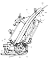
以下、植付装置5の給脂装置を図5乃至図8に基づいて説明すると、給脂装置はグリースカップ57、開閉弁58、ホース59、及びジョイント60、並びにノズル61等を用いて構成する。そして、グリースを貯留するグリースカップ57は、グリースを供給するニップル57aを設けた本体57bと、硬質透明プラスチック製のドーム57cを備え、本体57bの上部にドーム57cを螺合して一体的に連結して構成する。
Hereinafter, the greasing device of the
また、上記ドーム57cには、ピストンとピストンを押圧するスプリングを内蔵し、ニップル57aからスプリングに抗して本体57b及びドーム57c内に導いたグリースは、一旦、グリースカップ57内に貯留され、その後、スプリングによって押されたピストンによってグリースに与圧が与えられ、本体57b下部に設けた吐出口57dからグリースが吐出される。そして、グリースカップ57の吐出口57dには、グリースの吐出を止める(連通・遮断)開閉弁58を連結する。
The
さらに、以上のようになしたグリースカップ57と開閉弁58は、T字状のブラケット62に取り付けて、グリ−スカップアッシーを構成する。また、T字状のブラケット62を延長苗載台38dと共にネジ止めして、苗載台38の背面の上部にグリ−スカップアッシーを取り付ける。そして、透明、又は半透明な第1のビニールホース59aの始端側を、上端側のレール38fの後ろを通して、開閉弁58の出口に接続してクリップ63で止着する。
Further, the
また、第1のビニールホース59aの終端側にT型のジョイント60を接続してクリップ63で止着すると共に、ジョイント60の残る2つの接続部に第2と第3のビニールホース59b、59cの始端側を夫々接続してクリップ63で止着する。そして、第2と第3のビニールホース59b、59cを縦送りベルト46a、46aの上方に配索する苗切れセンサ47のハーネスを覆うコルゲートチューブ64に沿わせ、また、途中数箇所(3箇所)をワイヤバンド65でコルゲートチューブ64と共に苗載台38の背面に固定して、縦送りベルト46a、46aの上部を左右に迂回させて配管し、その後、第2と第3のビニールホース59b、59cの終端側を垂下させる。
In addition, a T-shaped joint 60 is connected to the terminal end side of the
一方、苗載台38の摺動部にグリースを供給するノズル61は、そのブラケット61aからやや前方側に傾斜して立ち上がる、ブラケット61aに溶接した鋼管61bによって形成し、このブラケット61aを苗載台38の下端側のレール38g上に下スライドピース52を取り付けるボルトを利用して取り付ける。また、鋼管61bの上端に第2、又は第3のビニールホース59b、59cの終端側を接続してクリップ63で止着する。
On the other hand, the
これにより、グリースはノズル61の先端からレール38gに穿設した連通孔r1とスライドピース52の連通孔r2を通り、スライドピース52の下面に形成した脂溜まりpに蓄えられる。なお、前述したホース59の配管に当たり、開閉弁58からジョイント60に至る第1のビニールホース59aは、二つのマット苗載置部38bの間に位置するガイドリブ38aの溝aを通すことで、植付装置5の他の構成要素との干渉を防止することができる。
Accordingly, the grease passes through the communication hole r1 formed in the
また、第1のビニールホース59aをガイドリブ38aの溝aに通し、且つ第2及び第3のビニールホース59b、59cを苗切れセンサ47のハーネスを覆うコルゲートチューブ64に沿わせてワイヤバンド65でコルゲートチューブ64と共に苗載台38の背面に固定する。さらに、ノズル61(鋼管61b)を縦送りベルト46aから離れるように前方側に傾斜して立ち上がるようになすと、不測にホース59が垂れ下がって縦送りベルト46aの駆動軸46b等に接触する虞が無くなり、配管が安定する。また、コルゲートチューブ64を固定するワイヤバンド65を用いてホース59を固定するから配管コストを削減でき、更にメンテナンス時にホース59を配管し直す際にも、残したワイヤバンド65に再度、ホース59を取り付ければよいから、間違える虞が無い。
Further, the
そして、以上のように構成する植付装置5の給脂装置は、例えば、植付作業を行う前にグリースガンにグリースをセットした状態で、開閉弁58を開いて、グリースカップ57のニップル57aにグリースガンを真っ直ぐ押し付けてグリースを充填する。この場合、開閉弁58は開いているから、目視によってホース59(第2及び第3のビニールホース59b、59c)の終端にグリースが充填されるまで、グリースを強制給脂する。
The grease supply device of the
また、グリースの強制給脂を行うと、グリースカップ57にグリースを最大量、貯留することになり、ここで、開閉弁58を一旦、閉じて植付作業の開始を待つ。そして、植付作業を開始する時には再び開閉弁58を開いて、グリースカップ57に貯留するグリースをスプリングによる与圧で徐々に潤滑箇所に供給する。なお、植付作業を終了したり休憩する際は、開閉弁58を閉じて潤滑剤の供給を止める。
When the grease is forcibly supplied, the maximum amount of grease is stored in the
従って、グリースの強制給脂を行いグリースカップ57にグリースを最大量、貯留させた状態で開閉弁58を開くと、苗載台38の摺動部にグリースが潤滑に必要な量ずつ過不足なく供給され続ける。また、これが植付作業を行う終日に亘って続くようにグリースカップ57の容量を定めておくと、開閉弁58の開閉操作は1日に1回行えばよいことになって、作業者は給脂操作を頻繁に行わなくとも済む。
Therefore, when the on-off
また、係る給脂操作は、機体4上から苗載台38の背面上部にある開閉弁58を開閉操作するだけであるから至って簡単であり、しかも、グリースカップ57へのグリースの充填にしても機体4上から行うことができるから、後輪3と植付装置5の間から身を乗り出して直接、グリース供給口に給脂を行うことが不要になり、給脂の作業時間を短縮することができる。
In addition, such a greasing operation is simple because it only opens and closes the opening / closing
しかも、グリースカップ57のドーム57cを透明とし、ホース59も透明、又は半透明とすると、グリースカップ57へのグリースの充填の要否、並びに潤滑箇所への潤滑剤の供給状態を目視することができ、それに応じた適切な対応を迅速に行うことができる。また、第1のビニールホース59aからジョイント60によって二股に分岐する第2及び第3のビニールホース59b、59cは、その管径、長さ、材質、及び曲りを同一、又は略同一として、苗載台38の二つの摺動部に配管するから、両者の配管抵抗が略同一となって潤滑剤を二つの潤滑箇所に均等に供給することができる。
Moreover, if the
さらに、本実施形態においては、前述した給脂装置を二組、植付装置5に取り付けて、各2箇所ずつ、合わせて4箇所を潤滑する。しかし、4箇所の潤滑箇所を一組の給脂装置で行う場合は、第1のホース59から先ず、第2及び第3のホース59に分岐させた後、第2及び第3のホース59から夫々二股に分岐させた4つの最終ホース59によって潤滑するようにしてもよく、この場合も各ホース59の配管長や曲がりを同一にして配管抵抗を等しくする。また、グリースカップ57の容量やスプリングの付勢力等を見直し、これを植付作業を終日、行った際に必要な潤滑量に基づいて適切に決定する。
Further, in the present embodiment, two sets of the above-described greasing devices are attached to the
なお、前述した給脂装置によって4箇所より多い潤滑箇所に給脂したり、或いは1箇所に給脂してもよく、また、配管抵抗を略同一にすることができるのなら、ジョイント60から分岐するホース59の長さ、曲がり等を必ずしも同一にする必要はなく、本発明は、前記実施形態に限定されるものではない。
It should be noted that more than four lubrication points may be lubricated by the above-described greasing device, or one location may be lubricated, and if the pipe resistance can be made substantially the same, branch from the joint 60 The lengths, bends, etc. of the
1 乗用型田植機(移植機)
2 前輪
3 後輪
4 機体
5 植付装置
38 苗載台
38a ガイドリブ
46a 縦送りベルト
47 苗切れセンサー
52 スライドピース(潤滑箇所)
53 プレート(潤滑箇所)
57 グリースカップ
58 開閉弁
59 ホース
60 ジョイント
61 ノズル
63 クリップ
65 ワイヤバンド
1 Passenger rice transplanter (Transplanter)
2
53 Plate (Lubricated part)
57
Claims (4)
前記ホースを、苗載台の隣接するマット苗載置部の間に設けるガイドリブの溝に通すと共に、ホースの中途にジョイントを設け、該ジョイントから二股に分岐する各ホースを縦送りベルトの上部を左右に迂回させて、苗切れセンサーのハーネスとともに苗載台の背面にワイヤバンドで固定して配管して構成し、
植付装置の稼動中に開閉弁を開いてグリースカップから潤滑箇所に潤滑剤を適量ずつ連続して供給することを特徴とする移植機。 In a transplanting machine in which a planting device is connected to a machine body including a front wheel and a rear wheel so as to be movable up and down, and a lubrication portion of the planting device is lubricated by a greasing device, the lubrication device stores a lubricant and lubricates with a spring. A grease cup that applies pressure to the agent, a hose that supplies lubricant to the lubrication point, and an on-off valve that communicates and blocks the oil passage between the grease cup and the hose ,
The hose is passed through a groove of a guide rib provided between adjacent mat seedling placement portions of the seedling mounting base, and a joint is provided in the middle of the hose, and each hose branched from the joint to the upper part of the vertical feed belt is provided. By detouring to the left and right, with the harness of the seedling shortage sensor fixed to the back of the seedling mounting stand with a wire band and configured by piping,
An transplanter characterized in that an on-off valve is opened during operation of the planting device, and an appropriate amount of lubricant is continuously supplied from the grease cup to the lubrication point.
The single member is formed into a T-shape composed of a reed and a reed, the reed is disposed on the back surface of the guide rib, and the left and right ends of the reed are the guide ribs on the back surface of the seedling platform of the planting device. 4. The transplanter according to claim 3 , wherein the transplanter is attached to the left and right outwards, the grease cup is attached to an upper side of an attachment surface projecting in the middle of the vertical shaft, and the on-off valve is attached to a lower side .
Priority Applications (1)
| Application Number | Priority Date | Filing Date | Title |
|---|---|---|---|
| JP2015116896A JP6571402B2 (en) | 2015-06-09 | 2015-06-09 | Transplanter |
Applications Claiming Priority (1)
| Application Number | Priority Date | Filing Date | Title |
|---|---|---|---|
| JP2015116896A JP6571402B2 (en) | 2015-06-09 | 2015-06-09 | Transplanter |
Publications (2)
| Publication Number | Publication Date |
|---|---|
| JP2017000066A JP2017000066A (en) | 2017-01-05 |
| JP6571402B2 true JP6571402B2 (en) | 2019-09-04 |
Family
ID=57750800
Family Applications (1)
| Application Number | Title | Priority Date | Filing Date |
|---|---|---|---|
| JP2015116896A Active JP6571402B2 (en) | 2015-06-09 | 2015-06-09 | Transplanter |
Country Status (1)
| Country | Link |
|---|---|
| JP (1) | JP6571402B2 (en) |
Family Cites Families (3)
| Publication number | Priority date | Publication date | Assignee | Title |
|---|---|---|---|---|
| JP3586884B2 (en) * | 1994-04-28 | 2004-11-10 | 井関農機株式会社 | Rice transplanter drawing marker device |
| JPH11190270A (en) * | 1997-12-26 | 1999-07-13 | Meidensha Corp | Device for preventing seizure of bearing of opening/ closing mechanism for hydraulic turbine |
| JP2000014217A (en) * | 1998-07-01 | 2000-01-18 | Kubota Corp | Lubricator of rice transplanter |
-
2015
- 2015-06-09 JP JP2015116896A patent/JP6571402B2/en active Active
Also Published As
| Publication number | Publication date |
|---|---|
| JP2017000066A (en) | 2017-01-05 |
Similar Documents
| Publication | Publication Date | Title |
|---|---|---|
| JP6571402B2 (en) | Transplanter | |
| JP2015149942A (en) | seedling transplanting machine | |
| CN101539238A (en) | Automatic lubricant dispenser using opposite directional pressurization | |
| KR100781413B1 (en) | Paddy field work machine | |
| KR101276324B1 (en) | Seedling transplanter | |
| JP5060252B2 (en) | Seedling stand guide structure of seedling planting device | |
| JP2011177052A5 (en) | ||
| RU2499178C2 (en) | System and method of lubing vehicle equipped with blade element | |
| JP2008154535A (en) | Seedling transplanter | |
| JP2017063622A (en) | Transplanter | |
| JP6485113B2 (en) | Working machine | |
| JP3427018B2 (en) | Lateral feed mechanism of seedling planting equipment | |
| CN110476559B (en) | Seedling planting device | |
| JP6640585B2 (en) | Transplant machine | |
| JP2007097542A (en) | Rice transplanter | |
| JP2017127266A (en) | Seedling transplanter | |
| JP2000014217A (en) | Lubricator of rice transplanter | |
| JP2016106544A (en) | Riding rice planting machine | |
| JP7161148B2 (en) | seedling transplanter | |
| JP2599324Y2 (en) | Rice transplanter | |
| JP2005176698A (en) | Sliding structure for seedling stand | |
| JP2012240494A (en) | Track roller-lubricating device for crawler traveling device | |
| JP4802840B2 (en) | Seedling transplanter | |
| KR101782748B1 (en) | Power take off | |
| JPH0120824Y2 (en) |
Legal Events
| Date | Code | Title | Description |
|---|---|---|---|
| A621 | Written request for application examination |
Free format text: JAPANESE INTERMEDIATE CODE: A621 Effective date: 20180330 |
|
| A977 | Report on retrieval |
Free format text: JAPANESE INTERMEDIATE CODE: A971007 Effective date: 20181227 |
|
| A131 | Notification of reasons for refusal |
Free format text: JAPANESE INTERMEDIATE CODE: A131 Effective date: 20190129 |
|
| A521 | Written amendment |
Free format text: JAPANESE INTERMEDIATE CODE: A523 Effective date: 20190328 |
|
| TRDD | Decision of grant or rejection written | ||
| A01 | Written decision to grant a patent or to grant a registration (utility model) |
Free format text: JAPANESE INTERMEDIATE CODE: A01 Effective date: 20190806 |
|
| A61 | First payment of annual fees (during grant procedure) |
Free format text: JAPANESE INTERMEDIATE CODE: A61 Effective date: 20190808 |
|
| R151 | Written notification of patent or utility model registration |
Ref document number: 6571402 Country of ref document: JP Free format text: JAPANESE INTERMEDIATE CODE: R151 |