JP6571179B2 - Flow control valve - Google Patents
Flow control valve Download PDFInfo
- Publication number
- JP6571179B2 JP6571179B2 JP2017521733A JP2017521733A JP6571179B2 JP 6571179 B2 JP6571179 B2 JP 6571179B2 JP 2017521733 A JP2017521733 A JP 2017521733A JP 2017521733 A JP2017521733 A JP 2017521733A JP 6571179 B2 JP6571179 B2 JP 6571179B2
- Authority
- JP
- Japan
- Prior art keywords
- valve body
- control valve
- cooling water
- flow control
- opening
- Prior art date
- Legal status (The legal status is an assumption and is not a legal conclusion. Google has not performed a legal analysis and makes no representation as to the accuracy of the status listed.)
- Active
Links
Images


Classifications
-
- F—MECHANICAL ENGINEERING; LIGHTING; HEATING; WEAPONS; BLASTING
- F01—MACHINES OR ENGINES IN GENERAL; ENGINE PLANTS IN GENERAL; STEAM ENGINES
- F01P—COOLING OF MACHINES OR ENGINES IN GENERAL; COOLING OF INTERNAL-COMBUSTION ENGINES
- F01P7/00—Controlling of coolant flow
- F01P7/14—Controlling of coolant flow the coolant being liquid
-
- F—MECHANICAL ENGINEERING; LIGHTING; HEATING; WEAPONS; BLASTING
- F01—MACHINES OR ENGINES IN GENERAL; ENGINE PLANTS IN GENERAL; STEAM ENGINES
- F01P—COOLING OF MACHINES OR ENGINES IN GENERAL; COOLING OF INTERNAL-COMBUSTION ENGINES
- F01P11/00—Component parts, details, or accessories not provided for in, or of interest apart from, groups F01P1/00 - F01P9/00
- F01P11/14—Indicating devices; Other safety devices
- F01P11/16—Indicating devices; Other safety devices concerning coolant temperature
-
- F—MECHANICAL ENGINEERING; LIGHTING; HEATING; WEAPONS; BLASTING
- F01—MACHINES OR ENGINES IN GENERAL; ENGINE PLANTS IN GENERAL; STEAM ENGINES
- F01P—COOLING OF MACHINES OR ENGINES IN GENERAL; COOLING OF INTERNAL-COMBUSTION ENGINES
- F01P7/00—Controlling of coolant flow
- F01P7/14—Controlling of coolant flow the coolant being liquid
- F01P7/16—Controlling of coolant flow the coolant being liquid by thermostatic control
- F01P7/165—Controlling of coolant flow the coolant being liquid by thermostatic control characterised by systems with two or more loops
-
- F—MECHANICAL ENGINEERING; LIGHTING; HEATING; WEAPONS; BLASTING
- F16—ENGINEERING ELEMENTS AND UNITS; GENERAL MEASURES FOR PRODUCING AND MAINTAINING EFFECTIVE FUNCTIONING OF MACHINES OR INSTALLATIONS; THERMAL INSULATION IN GENERAL
- F16K—VALVES; TAPS; COCKS; ACTUATING-FLOATS; DEVICES FOR VENTING OR AERATING
- F16K11/00—Multiple-way valves, e.g. mixing valves; Pipe fittings incorporating such valves
- F16K11/02—Multiple-way valves, e.g. mixing valves; Pipe fittings incorporating such valves with all movable sealing faces moving as one unit
- F16K11/08—Multiple-way valves, e.g. mixing valves; Pipe fittings incorporating such valves with all movable sealing faces moving as one unit comprising only taps or cocks
- F16K11/087—Multiple-way valves, e.g. mixing valves; Pipe fittings incorporating such valves with all movable sealing faces moving as one unit comprising only taps or cocks with spherical plug
- F16K11/0873—Multiple-way valves, e.g. mixing valves; Pipe fittings incorporating such valves with all movable sealing faces moving as one unit comprising only taps or cocks with spherical plug the plug being only rotatable around one spindle
- F16K11/0876—Multiple-way valves, e.g. mixing valves; Pipe fittings incorporating such valves with all movable sealing faces moving as one unit comprising only taps or cocks with spherical plug the plug being only rotatable around one spindle one connecting conduit having the same axis as the spindle
-
- F—MECHANICAL ENGINEERING; LIGHTING; HEATING; WEAPONS; BLASTING
- F16—ENGINEERING ELEMENTS AND UNITS; GENERAL MEASURES FOR PRODUCING AND MAINTAINING EFFECTIVE FUNCTIONING OF MACHINES OR INSTALLATIONS; THERMAL INSULATION IN GENERAL
- F16K—VALVES; TAPS; COCKS; ACTUATING-FLOATS; DEVICES FOR VENTING OR AERATING
- F16K11/00—Multiple-way valves, e.g. mixing valves; Pipe fittings incorporating such valves
- F16K11/10—Multiple-way valves, e.g. mixing valves; Pipe fittings incorporating such valves with two or more closure members not moving as a unit
- F16K11/105—Three-way check or safety valves with two or more closure members
-
- F—MECHANICAL ENGINEERING; LIGHTING; HEATING; WEAPONS; BLASTING
- F16—ENGINEERING ELEMENTS AND UNITS; GENERAL MEASURES FOR PRODUCING AND MAINTAINING EFFECTIVE FUNCTIONING OF MACHINES OR INSTALLATIONS; THERMAL INSULATION IN GENERAL
- F16K—VALVES; TAPS; COCKS; ACTUATING-FLOATS; DEVICES FOR VENTING OR AERATING
- F16K27/00—Construction of housing; Use of materials therefor
- F16K27/06—Construction of housing; Use of materials therefor of taps or cocks
- F16K27/067—Construction of housing; Use of materials therefor of taps or cocks with spherical plugs
-
- F—MECHANICAL ENGINEERING; LIGHTING; HEATING; WEAPONS; BLASTING
- F16—ENGINEERING ELEMENTS AND UNITS; GENERAL MEASURES FOR PRODUCING AND MAINTAINING EFFECTIVE FUNCTIONING OF MACHINES OR INSTALLATIONS; THERMAL INSULATION IN GENERAL
- F16K—VALVES; TAPS; COCKS; ACTUATING-FLOATS; DEVICES FOR VENTING OR AERATING
- F16K31/00—Actuating devices; Operating means; Releasing devices
- F16K31/02—Actuating devices; Operating means; Releasing devices electric; magnetic
- F16K31/025—Actuating devices; Operating means; Releasing devices electric; magnetic actuated by thermo-electric means
-
- F—MECHANICAL ENGINEERING; LIGHTING; HEATING; WEAPONS; BLASTING
- F16—ENGINEERING ELEMENTS AND UNITS; GENERAL MEASURES FOR PRODUCING AND MAINTAINING EFFECTIVE FUNCTIONING OF MACHINES OR INSTALLATIONS; THERMAL INSULATION IN GENERAL
- F16K—VALVES; TAPS; COCKS; ACTUATING-FLOATS; DEVICES FOR VENTING OR AERATING
- F16K31/00—Actuating devices; Operating means; Releasing devices
- F16K31/02—Actuating devices; Operating means; Releasing devices electric; magnetic
- F16K31/04—Actuating devices; Operating means; Releasing devices electric; magnetic using a motor
- F16K31/041—Actuating devices; Operating means; Releasing devices electric; magnetic using a motor for rotating valves
- F16K31/042—Actuating devices; Operating means; Releasing devices electric; magnetic using a motor for rotating valves with electric means, e.g. for controlling the motor or a clutch between the valve and the motor
-
- F—MECHANICAL ENGINEERING; LIGHTING; HEATING; WEAPONS; BLASTING
- F16—ENGINEERING ELEMENTS AND UNITS; GENERAL MEASURES FOR PRODUCING AND MAINTAINING EFFECTIVE FUNCTIONING OF MACHINES OR INSTALLATIONS; THERMAL INSULATION IN GENERAL
- F16K—VALVES; TAPS; COCKS; ACTUATING-FLOATS; DEVICES FOR VENTING OR AERATING
- F16K31/00—Actuating devices; Operating means; Releasing devices
- F16K31/02—Actuating devices; Operating means; Releasing devices electric; magnetic
- F16K31/04—Actuating devices; Operating means; Releasing devices electric; magnetic using a motor
- F16K31/041—Actuating devices; Operating means; Releasing devices electric; magnetic using a motor for rotating valves
- F16K31/043—Actuating devices; Operating means; Releasing devices electric; magnetic using a motor for rotating valves characterised by mechanical means between the motor and the valve, e.g. lost motion means reducing backlash, clutches, brakes or return means
-
- F—MECHANICAL ENGINEERING; LIGHTING; HEATING; WEAPONS; BLASTING
- F01—MACHINES OR ENGINES IN GENERAL; ENGINE PLANTS IN GENERAL; STEAM ENGINES
- F01P—COOLING OF MACHINES OR ENGINES IN GENERAL; COOLING OF INTERNAL-COMBUSTION ENGINES
- F01P11/00—Component parts, details, or accessories not provided for in, or of interest apart from, groups F01P1/00 - F01P9/00
- F01P11/14—Indicating devices; Other safety devices
- F01P11/18—Indicating devices; Other safety devices concerning coolant pressure, coolant flow, or liquid-coolant level
-
- F—MECHANICAL ENGINEERING; LIGHTING; HEATING; WEAPONS; BLASTING
- F01—MACHINES OR ENGINES IN GENERAL; ENGINE PLANTS IN GENERAL; STEAM ENGINES
- F01P—COOLING OF MACHINES OR ENGINES IN GENERAL; COOLING OF INTERNAL-COMBUSTION ENGINES
- F01P7/00—Controlling of coolant flow
- F01P7/14—Controlling of coolant flow the coolant being liquid
- F01P2007/146—Controlling of coolant flow the coolant being liquid using valves
-
- F—MECHANICAL ENGINEERING; LIGHTING; HEATING; WEAPONS; BLASTING
- F01—MACHINES OR ENGINES IN GENERAL; ENGINE PLANTS IN GENERAL; STEAM ENGINES
- F01P—COOLING OF MACHINES OR ENGINES IN GENERAL; COOLING OF INTERNAL-COMBUSTION ENGINES
- F01P2031/00—Fail safe
Description
本発明は、例えば自動車用冷却水の流量制御に供する流量制御弁に関する。 The present invention relates to a flow rate control valve used for controlling the flow rate of cooling water for automobiles, for example.
例えば自動車用冷却水の流量制御に適用される従来の流量制御弁としては、例えば以下の特許文献1に記載されたようなものが知られている。
For example, as a conventional flow control valve applied to the flow control of cooling water for automobiles, for example, the one described in
この流量制御弁は、ラジエータやヒータ等の補機に対する冷却水の分配制御に供するもので、軸方向一端側が導入口として開口形成されると共に、周壁に複数の排出口が開口形成されたほぼ筒状のハウジングと、該ハウジングの内周側に回転可能に収容され、軸方向一端側が前記導入口に向けて開口すると共に、周壁に複数の開口部が開口形成されたほぼ筒状の弁体と、を備え、前記弁体の回転位置、すなわち前記各開口部と前記各排出口との重合状態に応じて、前記導入口から導入した冷却水を、前記弁体の内周側通路及び前記重合状態にある開口部及び排出口を通じて前記各補機へと分配可能となっている。 This flow control valve is used to control the distribution of cooling water to auxiliary equipment such as radiators and heaters, and has an almost cylindrical shape in which one end in the axial direction is formed as an inlet and a plurality of outlets are formed in the peripheral wall. And a substantially cylindrical valve body that is rotatably accommodated on the inner peripheral side of the housing, has one axial end opening toward the introduction port, and a plurality of openings are formed in the peripheral wall. The cooling water introduced from the introduction port according to the rotational position of the valve body, that is, the polymerization state of each opening and each discharge port, and the inner circumferential side passage of the valve body and the polymerization It can be distributed to the auxiliary machines through the opening and the outlet in the state.
しかしながら、前記従来の流量制御弁では、冷却水が弁体の内周側通路から各排出口へと流出する際、導入口の流路断面積に対して各排出口の流路断面積が小さくなっていて、導入口と各排出口との間で流路断面積が急激に縮小する構成となっていることから、該縮小部における水流によどみを招来し、これによって冷却水の通流抵抗が増大してしまう問題があった。 However, in the conventional flow control valve, when cooling water flows out from the inner circumferential side passage of the valve body to each discharge port, the flow passage cross-sectional area of each discharge port is smaller than the flow passage cross-sectional area of the introduction port. Since the cross-sectional area of the flow path is rapidly reduced between the inlet and each outlet, stagnation is caused by the water flow in the reduced portion, and thereby the flow resistance of the cooling water. There was a problem that increased.
本発明はかかる技術的課題に鑑みて案出されたものであり、流体の通流抵抗を低減し得る流量制御弁を提供することを目的としている。 The present invention has been devised in view of such technical problems, and an object of the present invention is to provide a flow control valve that can reduce the flow resistance of a fluid.
本発明は、中空状の弁体収容部の軸方向に開口形成され、流体の導入に供する導入口と、前記導入口の開口横断面よりも小さな開口横断面となるように形成され、前記弁体収容部と径方向から連通して当該弁体収容部内の流体の排出に供する複数の排出口とを有するハウジングと、前記ハウジング内に回転可能に支持され、その回転位置に応じて前記各排出口との重合状態が変化する複数の開口部を有する弁体と、を備え、前記弁体収容部の軸方向において、前記導入口から少なくとも1つの前記排出口に向かう間の開口横断面を縮小したことを特徴としている。 The present invention has an opening formed in the axial direction of a hollow valve body housing portion, and is formed so as to have an introduction port for introducing fluid and an opening cross section smaller than the opening cross section of the introduction port. A housing having a plurality of discharge ports communicating with the body housing portion in the radial direction and used for discharging the fluid in the valve body housing portion, and rotatably supported in the housing, and each of the discharge ports depending on the rotation position. A valve body having a plurality of openings in which the polymerization state with the outlet changes, and in the axial direction of the valve body housing portion, the opening cross section between the introduction port and at least one discharge port is reduced. It is characterized by that.
なお、前記開口横断面の縮小に係る一の態様として、弁体収容部内における弁体の径方向外側にバイパス通路を設け、該バイパス通路によって副流を構成することで前記開口横断面を縮小することが望ましい。 As one aspect related to the reduction of the opening cross section, a bypass passage is provided outside the valve body in the radial direction of the valve body, and the side cross section is formed by the bypass passage to reduce the opening cross section. It is desirable.
また、前記開口横断面の縮小に係る他の態様として、ハウジング又は弁体の開口横断面を徐々に縮小させることが望ましい。このように、開口横断面を徐々に縮小させることで、流体の通流抵抗をより効果的に低減することができる。 Further, as another aspect relating to the reduction of the opening cross section, it is desirable to gradually reduce the opening cross section of the housing or the valve body. Thus, the flow resistance of the fluid can be more effectively reduced by gradually reducing the opening cross section.
本発明によれば、弁体収容部の軸方向における導入口から少なくとも1つの排出口に向かう間の開口横断面を縮小させることによって、流体の流路断面積の急激な縮小を抑制することが可能となり、流体の通流抵抗を低減することができる。 According to the present invention, it is possible to suppress a rapid reduction in the flow path cross-sectional area of the fluid by reducing the opening cross section between the introduction port in the axial direction of the valve body housing portion and at least one discharge port. It becomes possible, and the flow resistance of the fluid can be reduced.
以下、本発明に係る流量制御弁の各実施形態を図面に基づき説明する。なお、下記の実施形態では、本発明に係る流量制御弁を従来と同様の自動車用冷却水(以下、単に「冷却水」と略称する。)の循環系に適用したものを例に説明する。 Embodiments of a flow control valve according to the present invention will be described below with reference to the drawings. In the following embodiment, a flow control valve according to the present invention will be described as an example in which the flow control valve according to the present invention is applied to a circulating system for automotive cooling water (hereinafter simply referred to as “cooling water”).
〔第1実施形態〕
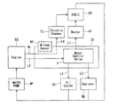
図1〜図13は本発明に係る流量制御弁の第1実施形態を示し、まず、この流量制御弁CVが適用される冷却水の循環回路について説明すると、図1に示すように、当該流量制御弁CVは、エンジンEG(具体的には、図示外のシリンダヘッド)の側部に配置され、該エンジンEGと暖房熱交換器HT(EGRクーラEC)、オイルクーラOC及びラジエータRDとの間に配置されている。そして、ウォータポンプWPによって加圧され導入通路L0を通じて当該流量制御弁CVに導かれた冷却水が、第1〜第3配管L1〜L3を介して暖房熱交換器HT、オイルクーラOC及びラジエータRD側へとそれぞれ分配されると共に、その各流量が制御されるようになっている。なお、この際、前記暖房熱交換器HTへと導かれた冷却水については、EGRクーラECへと導かれた後、エンジンEG側へと還流されるようになっている。[First Embodiment]
1 to 13 show a first embodiment of a flow control valve according to the present invention. First, a cooling water circulation circuit to which the flow control valve CV is applied will be described. As shown in FIG. The control valve CV is disposed at a side portion of the engine EG (specifically, a cylinder head (not shown)), and between the engine EG and the heating heat exchanger HT (EGR cooler EC), the oil cooler OC, and the radiator RD. Is arranged. Then, the cooling water pressurized by the water pump WP and guided to the flow control valve CV through the introduction passage L0 is supplied to the heating heat exchanger HT, the oil cooler OC, and the radiator RD via the first to third pipes L1 to L3. Each flow is distributed to the side, and each flow rate is controlled. At this time, the cooling water led to the heating heat exchanger HT is led to the EGR cooler EC and then returned to the engine EG side.
また、前記流量制御弁CVには、前記導入通路L0をバイパスして冷却水をスロットルチャンバーTCへと直接導くバイパス通路BLが設けられ、該バイパス通路BLをもって、エンジンEG側から導かれた冷却水を常時スロットルチャンバーTCへと供給可能となっている。そして、該スロットルチャンバーTCに供給された冷却水は、前記暖房熱交換器HTと同様、EGRクーラECへと導かれて、該EGRクーラECを通じてエンジンEG側へと還流される。図1中における符号WTは水温センサを示している。 Further, the flow rate control valve CV is provided with a bypass passage BL that bypasses the introduction passage L0 and directly leads the cooling water to the throttle chamber TC, and the cooling water guided from the engine EG side with the bypass passage BL. Can always be supplied to the throttle chamber TC. Then, the cooling water supplied to the throttle chamber TC is guided to the EGR cooler EC and is returned to the engine EG side through the EGR cooler EC, similarly to the heating heat exchanger HT. A symbol WT in FIG. 1 indicates a water temperature sensor.
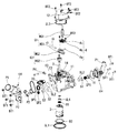
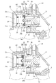
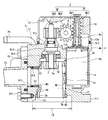
続いて、前記流量制御弁CVの具体的な構成について説明すると、この流量制御弁CVは、図2、図10に示すように、後述の弁体3及び電動モータ4を収容する第1ハウジング11と後述する減速機構5を収容する第2ハウジング12とからなるハウジング1と、第1ハウジング11と第2ハウジング12とを隔成する第1ハウジング11の端壁11bに挿通配置され、該端壁11bに保持される軸受B1によって回転可能に支持された回転軸2と、該回転軸2の一端部に固定され、第1ハウジング11内にて回転可能に収容されたほぼ円筒状の弁体3と、第1ハウジング11内にて弁体3と並列に配置され、弁体3の駆動制御に供する電動モータ4と、該電動モータ4のモータ出力軸4cと回転軸2との間に介装され、電動モータ4の回転速度を減速して伝達する減速機構5と、から主として構成されている。
Subsequently, the specific configuration of the flow control valve CV will be described. As shown in FIGS. 2 and 10, the flow control valve CV includes a
前記第1ハウジング11は、アルミニウム合金材料によって鋳造されてなるもので、幅方向一端側に偏倚して弁体3を収容するほぼ筒状の弁体収容部13が軸方向一端側に向けて開口形成されると共に、該弁体収容部13に隣接するかたちで、幅方向他端側に偏倚して電動モータ4を収容するほぼ筒状のモータ収容部14が軸方向他端側に向けて開口形成され、前記弁体収容部13の一端側開口の外周域に延設される第1フランジ部11aを介して図示外のエンジンの側部に図示外のボルトによって取付固定されている。なお、かかる取付の際、第1ハウジング11の第1フランジ部11aと前記エンジン側部との間には環状のシール部材SL1が介装され、該シール部材SL1によって弁体収容部13内が液密に保持される構成となっている。
The
前記弁体収容部13は、前記軸方向一端側に段差状に拡径形成された導入口10を通じて図示外のエンジン内部と連通し、該エンジン内部からの冷却水が導入されるようになっている。ここで、本発明において、前記導入口10は、図8に示すように、前記弁体収容部13の一端側開口を指すのでははく、前記エンジン内部と接続する第1フランジ部11aの開口を指している。すなわち、弁体収容部13の軸方向一端側においては、前記導入口10が最大径でもって前記エンジン内部に開口し、該導入口10から開口横断面が段差状に縮小するかたちで当該弁体収容部13が開口形成されている。
The valve
そして、前記弁体収容部13の内部では、弁体3が収容配置されることで、当該弁体3の内周側に形成され、主流を構成する内周側通路17と、当該弁体3の外周側に形成され、前記主流とは別のバイパス流を構成する本発明に係るバイパス通路としての外周側通路18と、が隔成される。すなわち、前記導入口10より導かれた冷却水は、該導入口10から前記内周側通路17及び外周側通路18へそれぞれ直接流入し、該各通路17,18を経て後述する各排出口E1〜E3で合流し排出されることとなる。
And in the inside of the said valve
ここで、前記流量制御弁CVでは、前記弁体収容部13の軸方向において、導入口10から少なくとも後述する1つの排出口(本実施形態では、第3排出口E3)に向かう間の、前記導入口10並びに内周側通路17及び外周側通路18を含めた開口横断面(図4中のF−F線断面)が、段階的に縮小するように構成されている。
Here, in the flow rate control valve CV, in the axial direction of the valve
また、後述する各排出口E1〜E3の開口横断面は、前記導入口10の開口横断面よりも小さくなるように形成されている。すなわち、導入口10から各排出口E1〜E3への開口横断面は、導入口10で最も大きく、各排出口E1〜E3で最も小さくなるように構成されている。
Moreover, the opening cross section of each discharge port E1-E3 mentioned later is formed so that it may become smaller than the opening cross section of the said
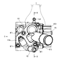
前記弁体収容部13の周壁には、所定の周方向位置に、前記第1〜第3配管L1〜L3(図1参照)と接続することで前記冷却水の排出に供するほぼ円筒状の複数の第1〜第3排出口E1〜E3が径方向に貫通形成されている。これら第1〜第3排出口E1〜E3のうち、暖房熱交換器HTと連通する中径状の第1排出口E1と、オイルクーラOCと連通する小径状の第2排出口E2と、が弁体収容部13の軸方向において重合(径方向にほぼ対向)して配置されると共に、オイルクーラOCと連通する小径状の第2排出口E2と、ラジエータRDと連通する大径状の第3排出口E3と、が弁体収容部13の軸方向に並列に隣接して配置されていて、第1、第2排出口E1,E2が導入口10側に、第3排出口E3が端壁11b側に、それぞれ偏倚して設けられている。
On the peripheral wall of the valve
ここで、前記第1〜第3排出口E1〜E3は、図3に示すように、それぞれ後述する第1〜第3排出管P1〜P3を介して前記第1〜第3配管L1〜L3(図1参照)に接続されるようになっている。すなわち、前記弁体収容部13の外周部には、後述する第1排出管P1を構成する第1アウトレットO1が径方向の一方側に、後述する第2、第3排出管P2,P3を構成する第2アウトレットO2が他方側に、それぞれ複数のボルトBT1でもって取付固定されている。
Here, as shown in FIG. 3, the first to third discharge ports E1 to E3 are connected to the first to third pipes L1 to L3 (via first to third discharge pipes P1 to P3, which will be described later, respectively. (See FIG. 1). That is, a first outlet O1 constituting a first discharge pipe P1 to be described later is formed on the outer peripheral portion of the valve
前記第1アウトレットO1は、弁体収容部13の外周部であって第1排出口E1の外端側開口縁への取付固定に供するフランジO1aと、該フランジO1aの外側部に突出形成され、第1排出口E1から排出された冷却水を第1配管L1へと導く第1排出管P1と、が一体に成形されることによって構成されている。
The first outlet O1 is an outer peripheral part of the valve
前記第2アウトレットO2は、図3、図5に示すように、弁体収容部13の外周部であって第2、第3排出口E2,E3の外端側開口縁への取付固定に供するフランジO2aと、該フランジO2aの外側部にそれぞれ突出形成され、第2、第3排出口E2,E3から流出した冷却水を第2、第3配管L2,L3へと導く第2排出管P2及び第3排出管P3と、が一体に成形されることによって構成されている。
As shown in FIGS. 3 and 5, the second outlet O <b> 2 is an outer peripheral portion of the valve
また、前記第1〜第3排出口E1〜E3の内周側には、該第1〜第3排出口E1〜E3を閉じる際に該各排出口E1〜E3と弁体3との間を液密にシールするシール手段が設けられている。このシール手段は、各排出口E1〜E3の内端側において進退移動可能に収容され、弁体3の外周面に摺接することで各排出口E1〜E3と弁体3との間をシールするほぼ円筒状の第1〜第3シール部材S1〜S3と、各排出口E1〜E3の外端側において各排出管P1〜P3の開口縁(第1排出管P1についてはリテーナ部材16)に着座させるかたちで該各排出管P1〜P3の開口縁と各シール部材S1〜S3の内側端面との間に所定の予圧をもって弾装され、該各シール部材S1〜S3を弁体3側へと付勢する第1〜第3コイルスプリングSP1〜SP3と、各排出口E1〜E3の内周面に切欠形成された凹部に収容されるかたちで各排出口E1〜E3の内周面と各シール部材S1〜S3の外周面との間に介装され、該各シール部材S1〜S3の外周面と摺接することで各排出口E1〜E3と各シール部材S1〜S3との間をシールする周知のOリングSL2と、から構成されている。
Further, on the inner peripheral side of the first to third discharge ports E1 to E3, when the first to third discharge ports E1 to E3 are closed, a space between the discharge ports E1 to E3 and the
前記各シール部材S1〜S3は、弁体3側となる一端側の内周縁に、後述の第1〜第3シール摺接部D1〜D3と摺接するほぼ円錐テーパ状に形成された第1〜第3弁体摺接部S1a〜S3aが設けられている一方、他端側には、各コイルスプリングSP1〜SP3の一端側の着座に供する平坦状の第1〜第3着座面S1b〜S3bが形成されている。かかる構成から、前記各弁体摺接部S1a〜S3aについては、前記各シール摺接面D1〜D3に対して、厚さ幅方向(径方向)の中間部のみが摺接する、いわゆる線接触をもって摺接するようになっている。
Each of the sealing members S1 to S3 is formed in a substantially conical taper shape that is slidably contacted with first to third seal sliding contact portions D1 to D3 described later on the inner peripheral edge on one end side that is the
また、前記弁体収容部13の他端側には、図5、図6に示すように、内端側が外周側通路18へと臨み、かつ外端側に第4排出管P4が接続されることで冷却水をスロットルチャンバーTCへと導くバイパス通路用排出口である第4排出口E4が貫通形成され、これによって前記バイパス通路BL(図1参照)が構成されている。すなわち、かかる構成より、外周側通路18に導かれた冷却水を、後述する弁体3の回動位相にかかわらず常に第4排出管P4から排出させ、前記第4配管L4(図1参照)を介してスロットルチャンバーTCへ分配することが可能となっている。
Further, as shown in FIGS. 5 and 6, the inner end side faces the outer
さらに、前記第3排出口E3の側部には、図2、図6、図7に示すように、例えば電気系が失陥した時など弁体3が駆動不能となった非常時に弁体収容部13(外周側通路18)と第3排出口E3とを連通可能にするフェールセーフバルブ20が設けられていて、弁体3の不動状態であっても、ラジエータRDに対する冷却水の供給を確保することにより、エンジンEGのオーバーヒートを防ぐことが可能となっている。
Further, as shown in FIGS. 2, 6, and 7, the side of the third discharge port E3 accommodates the valve body in an emergency when the
前記フェールセーフバルブ20は、弁体収容部13の周壁に貫通形成された貫通孔11cに嵌挿され、内周側に外周側通路18と第3排出管P3(後述の排出室27)とを連通する流路としての連通口26を構成するほぼ筒状の流路構成部材であるバルブボディ21と、該バルブボディ21の内端側に収容され、冷却水温が所定温度を超えると内部に充填された図示外のワックスが膨張することでロッド22aが開弁方向へ進出するように構成されたサーモエレメント22と、該サーモエレメント22のロッド22aに固定され、前記連通口26の開閉に供する弁部材23と、該弁部材23と対向するかたちでバルブボディ21の外端部(後述するアーム部21bの支持片部21c)に支持されるほぼ円板状のリテーナ部材24と、該リテーナ部材24と弁部材23の間に所定の予圧をもって弾装され、弁部材23を閉弁方向へと付勢するコイルスプリング25と、から主として構成されている。
The fail-
前記バルブボディ21は、ほぼ段差径状を呈し、前記サーモエレメント22の収容保持に供する小径状のボディ本体21aと、該ボディ本体21aの外端側における周方向所定位置に突設され、前記リテーナ部材24の支持に供する複数のアーム部21bと、を備える。そして、前記各アーム部21bの先端部には、ほぼ爪状に構成された支持片部21cが径方向内側へと曲折形成されていて、該各支持片部21cに前記リテーナ部材24が支持される構成となっている。
The
前記弁部材23は、前記サーモエレメント22のロッド22aとの固定に供する芯金23aと、該芯金23aの外周縁部を覆うように設けられ、閉弁時におけるバルブボディ21との密着性の向上に供するゴム製の被覆23bと、を備える。そして、この弁部材23の被覆23bがボディ本体21aの外端開口縁に離着座することで、前記連通口26が開閉されるようになっている。
The
このようにして、通常状態(冷却水温が所定温度未満)では、コイルスプリング25の付勢力でもって弁部材23の被覆23bが連通口26の外側孔縁に圧接することにより閉弁状態が維持される。一方、高温状態(冷却水温が所定温度以上)になると、前記サーモエレメント22内のワックスが膨張して前記コイルスプリング25の付勢力に抗してロッド22aと共に弁部材23が外端側へと後退移動することにより開弁され、図示外の流入孔と前記連通口26とが連通することとなって、外周側通路18に導かれた冷却水が第3排出管P3より排出され、前記第3配管L3(図1参照)を通じてラジエータRDへと供給されることとなる。
In this way, in the normal state (cooling water temperature is lower than the predetermined temperature), the closed state is maintained by the
なお、かかる温度上昇のほか、冷却水の圧力が所定圧力を超えた場合にも、弁部材23がコイルスプリング25の付勢力に抗して押し退けられることで、前記図示外の流入孔と連通口26とが連通して、これによって流量制御弁CVの内部圧力が減少する結果、該流量制御弁CVの故障を回避することが可能となっている。
In addition to such a temperature rise, when the pressure of the cooling water exceeds a predetermined pressure, the
前記第2ハウジング12は、図2、図10に示すように、第1ハウジング11と対向する一端側が弁体収容部13とモータ収容部14とに跨って該両収容部13,14を覆うように開口する凹状に形成され、該一端側開口の外周域に延設される第2フランジ部12aを介して第1ハウジング11の他端側に複数のボルトBT2によって固定されることで、該第1ハウジング11の他端側との間に、減速機構5を収容する減速機構収容部15が形成されている。なお、前記第1、第2ハウジング11,12の接合に際しては、該接合面間に環状のシール部材SL3が介装されることによって、減速機構収容部15内が液密に保持されている。
As shown in FIGS. 2 and 10, the
前記回転軸2は、弁体収容部13の他端壁に相当する前記端壁11bに貫通形成された軸挿通孔11d内に収容配置される前記軸受B1によって回転可能に支持され、軸方向の一端部には弁体3が、他端部には後述する第2斜歯歯車HG2がそれぞれ一体回転可能に固定される。なお、この回転軸2の外周面と軸挿通孔11dの内端側開口縁との間には環状のシール部材SL4が介装されていて、該シール部材SL4によって、前記軸挿通孔11dと回転軸2との間の径方向隙間を通じた弁体収容部13側から減速機構収容部15への冷却水の流入が抑止されている。
The
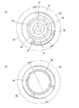
前記弁体3は、所定の合成樹脂材料により一体に型成形され、図4、図11に示すように、軸方向一端側が、第1ハウジング11の導入口10より導入される冷却水の内周側通路17への流入に供する流入口3aとして開口形成されている。ここで、この弁体3は、特に図4に示すように、軸方向一端側から他端側へ向けて内径が漸次縮小するように構成されることによって、内周側通路17の流路断面積が、前記流入口3aから第3開口部M3へ向けて徐々に縮小する構成となっている。具体的には、前記弁体3の内周面が他端側へと向けて漸次縮径する円錐テーパ状のテーパ部30を設けることにより、前述の内周側通路17の流路断面積の縮小が実現されている。
The
なお、かかる弁体3の内径の縮小については、図4のような一連のテーパ部30の他に、例えば図14、図15に示すような、複数のテーパ部である第1〜第3テーパ部31〜33によって内径を変化させる構成としてもよい。具体的には、後述する第1、第2軸方向領域X1,X2に対応する内周面を第1、第2テーパ部31,32として構成すると共に、これら両テーパ部31,32の接続部を第3テーパ部33として構成し、第1テーパ部31から第3テーパ部33、第3テーパ部33から第2テーパ部32へと、これら各テーパ部31〜33毎に弁体3の内径を徐々に縮小変化させる構成としてもよい。
In addition, about the reduction | decrease of the internal diameter of this
ここで、第1テーパ部31と第2テーパ部32との接続については、図14に示すように第1、第2テーパ部31,32に対して第3テーパ部33の傾斜を大きく設定して該第3テーパ部33のみによって滑らかに接続してもよく、また、図15に示すように前記各テーパ部31〜33をほぼ同じ傾斜に設定して階段状に接続してもよい。換言すれば、前記各テーパ部31〜33の数量は勿論、該各テーパ部31〜33の接続態様についても、流量制御弁CVの仕様やコスト等に応じて任意に設定することができる。
Here, with respect to the connection between the
上述のように、前記各テーパ部31〜33による内径縮小構成とすることで、内周側通路17の流路断面積の縮小率をより低減させて、該流路断面積の縮小量をより滑らかにすることができる。さらには、前記各テーパ部31〜33によって、弁体3の全体の肉厚(径方向幅)をより小さくすることができ、これによって弁体3の回動性向上や冷却水の流量増大に供されるといったメリットがある。
As described above, by reducing the inner diameter by the tapered
一方、他端側は端壁3bによって閉塞されると共に、該端壁3bには、内周側通路17と外周側通路18とを連通可能にするほぼ円弧状の複数の連通口3cが周方向に沿って切欠形成されている。なお、当該各連通口3cによっても、後述する補助吸入口M4と共に、本発明に係るバイパス孔が構成されている。そして、この弁体3の軸心に相当する前記端壁3bの中央部には、前記回転軸2への取付に供するほぼ筒状の軸固定部3dが軸方向に沿って延設されると共に、該軸固定部3dの内周側には、金属製のインサート部材3eが一体に成形され、該インサート部材3eを介して回転軸2に圧入固定されるようになっている。
On the other hand, the other end side is closed by the
また、前記弁体3は、その外形が、前記各シール部材S1〜S3と摺接することにより閉弁時のシール作用に供するほぼ球面状のシール摺接部(後述する第1〜第3シール摺接部D1〜D3)を軸方向に直列に連接してなる団子形状に形成され、周方向約180°の所定の角度範囲内で回動することにより前記各排出口E1〜E3の開閉が行われるようになっている。なお、かかる回動に際し、この弁体3は、一端部に大径状に拡径形成された軸受部3gを介して、弁体収容部13の一端側に嵌着保持される軸受B2により回転支持されている。
Further, the
ここで、前記弁体3は、前記各シール摺接部D1〜D3の形成にあたって、一端側の第1軸方向領域X1と、他端側の第2軸方向領域X2、2つの軸方向領域に大別される。なお、この第1、第2軸方向領域X1,X2は、弁体3の軸方向ほぼ中間位置を境にほぼ均等に形成されている。そして、このいずれの軸方向領域X1,X2においても、少なくとも後述する第1〜第3開口部M1〜M3の孔縁が縦断面ほぼ球面状、すなわちほぼ同一の曲率を有する曲面状に形成されると共に、該曲率が弁体3の回転半径と同一となるように構成されている。
Here, in forming the seal sliding contact portions D1 to D3, the
前記第1軸方向領域X1は、図12(b)に示すように、ほぼ半周に亘って設けられ、第1シール部材S1と摺接する第1シール摺接部D1と、残余のほぼ半周に亘って設けられ、第2シール部材S2と摺接する第2シール摺接部D2と、で構成される。そして、前記第1シール摺接部D1には、第1排出口E1とほぼ過不足なく重合する軸方向幅に設定された長孔形状の第1開口部M1が、周方向に沿って設けられている。同様に、前記第2シール摺接部D2には、第2排出口E2とほぼ過不足なく重合する軸方向幅に設定された長孔形状の第2開口部M2が、周方向に沿って設けられている。 As shown in FIG. 12B, the first axial direction region X1 is provided over almost a half circumference, and covers the first seal sliding contact portion D1 that is in sliding contact with the first seal member S1, and the remaining almost half circumference. And a second seal sliding contact portion D2 that is in sliding contact with the second seal member S2. The first seal sliding contact portion D1 is provided with a first opening portion M1 having a long hole shape that is set to have an axial width that overlaps with the first discharge port E1 almost without excess or shortage along the circumferential direction. ing. Similarly, the second seal sliding contact portion D2 is provided with a second opening portion M2 having a long hole shape that is set to have an axial width that overlaps with the second discharge port E2 substantially without excess or deficiency along the circumferential direction. It has been.
このように、本実施形態に係る弁体3では、前記第1開口部M1と前記第2開口部M2とが前記第1軸方向領域X1における異なる周方向位置に弁体3の回転軸方向において重合するように設けられていることで、弁体3の軸方向の小型化が図られている。
Thus, in the
前記第2軸方向領域X2は、図12(a)に示すように、半周以上に亘って設けられ、第3シール部材S3と摺接する第3シール摺接部D3と、残余の周方向領域に亘って設けられ、第3排出口E3とは対向せず前記第3シール部材S3によるシール作用に供しない非シール摺接部D4と、で構成される。そして、前記第3シール摺接部D3には、第3排出口E3とほぼ過不足なく重合する軸方向幅に設定された長孔形状の第3開口部M3が、周方向に沿って設けられている。 As shown in FIG. 12 (a), the second axial region X2 is provided over a half circumference and includes a third seal sliding contact portion D3 that is in sliding contact with the third seal member S3, and a remaining circumferential region. And a non-seal sliding contact portion D4 that does not face the third discharge port E3 and does not provide a sealing action by the third seal member S3. The third seal sliding contact portion D3 is provided with a long-hole-shaped third opening M3 set in the circumferential direction so as to overlap with the third discharge port E3 without substantial excess or deficiency. ing.
ここで、前記第3開口部M3は、図11に示すように、周方向に沿った前記長孔形状に形成されていることにより、第3排出口E3との重合時、すなわち当該第3排出口E3の開弁時には、図9に示すように、内周側通路17の冷却水(後述する補助吸入口M4等を介して外周側通路18から内周側通路17へと流入したものを含む)が、第3開口部M3を通じて第3排出口E3に流入すると共に、外周側通路18の冷却水が、周方向端部側の外周側通路18に臨む開口(以下、「直接連通部」という。)TXを介して第3排出口E3に直接流入するようになっている。一方、前記第3排出口E3の閉弁時には、該第3排出口E3が第3シール摺接部D3のうち第3開口部M3を除く周方向領域により閉塞される結果、前記第3開口部M3を通じた内周側通路17側からの冷却水は勿論、前記直接連通部TXを通じた外周側通路18側からの冷却水も同時に遮断されることとなる。
Here, as shown in FIG. 11, the third opening M3 is formed in the shape of the long hole along the circumferential direction, so that the third outlet M3 is overlapped with the third outlet E3, that is, the third outlet. When the outlet E3 is opened, as shown in FIG. 9, the cooling water in the inner peripheral side passage 17 (including water flowing into the inner
また、前記非シール摺接部D4には、図11に示すように、平面視ほぼ矩形状をなす本発明に係るバイパス孔としての補助吸入口M4が、周方向に沿って設けられている。なお、この補助吸入口M4は、図9に示すように、外周側通路18を流れる冷却水を内周側通路17へと導き入れ、前記外周側通路18を通流するバイパス流を、前記内周側通路17を通流する主流へと合流させることに供するものである。加えて、前記非シール摺接部D4は、いわゆる不使用領域であることから、ほぼ球面状に形成される前記第1〜第3シール摺接部D1〜D3とは異なり、非球面状となる平坦状に形成され、これによって弁体3の軽量化及び該弁体3を構成する材料の歩留まりの低減が図られている。
Further, as shown in FIG. 11, the non-seal sliding contact portion D4 is provided with an auxiliary suction port M4 as a bypass hole according to the present invention having a substantially rectangular shape in plan view along the circumferential direction. As shown in FIG. 9, the auxiliary suction port M4 guides the coolant flowing through the outer
以上のようにして設けられる前記第1〜第3開口部M1〜M3の各形状及び周方向位置については、弁体3の回動に伴って図13に示した後述する第1〜第4状態の順に前記第1〜第3排出口E1〜E3との連通状態が切り替わるように設定されている。 About each shape and circumferential direction position of the said 1st-3rd opening part M1-M3 provided as mentioned above, the 1st-4th state mentioned later shown in FIG. The communication states with the first to third discharge ports E1 to E3 are set in this order.
また、前記弁体3の他端部における第3シール摺接部D3には、該弁体3の回動規制に供する1対の当接部3f,3fが設けられている。この当接部3f,3fは、図11、図12に示すように、前記弁体収容部13の他端側周壁に突設される回転規制部11eと当接可能に設けられ、該回転規制部11eと当接することで弁体3の回動範囲が前記所定角度範囲内に規制されるようになっている。なお、この当接部3f,3fは、前記弁体3の構成に伴い必然的に設けられるものであるから、該当接部3f,3fを利用することによって、前記回動規制用のストッパを別途設ける必要がなく、流量制御弁CVのコスト低減等に供される。
The third seal sliding contact portion D3 at the other end of the
前記電動モータ4は、図2、図10に示すように、モータ本体4aが第1ハウジング11のモータ収容部14内に収容された状態でモータ本体4aの基端部に設けられたフランジ部4bを介して当該モータ収容部14の開口縁部に複数のボルトBT3によって取付固定され、モータ出力軸4cがモータ収容部14の一端側開口を通じて第2ハウジング12の減速機構収容部15内へと臨んでいる。なお、この電動モータ4は、車載の電子コントローラ(図示外)により駆動制御され、車両運転状態に応じて弁体3を回動制御することにより、前記ラジエータRD等に対する冷却水の適切な分配が実現される。
As shown in FIGS. 2 and 10, the
前記減速機構5は、2つのウォームギヤにより構成された駆動機構であって、モータ出力軸4cと連係し、電動モータ4の回転を減速する第1ウォームギヤG1と、該第1ウォームギヤG1に接続され、この第1ウォームギヤG1を介して伝達される電動モータ4の回転をさらに減速して回転軸2に伝達する第2ウォームギヤG2と、から構成され、前記第2ウォームギヤG2は、前記第1ウォームギヤG1に対しほぼ直交するかたちで配置されている。
The
前記第1ウォームギヤG1は、モータ出力軸4cの外周に一体的に設けられ、該モータ出力軸4cと一体回転する第1ねじ歯車WG1と、モータ回転軸4cとほぼ平行に前記第1ねじ歯車WG1と直交するかたちで設けられる回転軸19の一端側外周に一体的に設けられ、前記第1ねじ歯車WG1と噛合することにより該第1ねじ歯車WG1の回転を減速して出力する第1斜歯歯車HG1と、で構成されている。そして、この第1ウォームギヤG1は、前記第1ねじ歯車WG1が1条ねじによって構成されると共に、前記第1斜歯歯車HG1が14歯でもって構成されていて、減速比が1/14に設定されている。
The first worm gear G1 is integrally provided on the outer periphery of the
前記第2ウォームギヤG2は、前記回転軸19の他端側外周に一体的に設けられ、前記第1斜歯歯車HG1と一体回転する第2ねじ歯車WG2と、該第2ねじ歯車WG2と直交するかたちで配置される回転軸2の他端側外周に一体回転可能に固定され、前記第2ねじ歯車WG2と噛合することで該第2ねじ歯車WG2の回転を減速して出力する第2斜歯歯車HG2と、で構成されている。そして、この第2ウォームギヤG2も、前記第1ウォームギヤG1と同様に、前記第2ねじ歯車WG2が1条ねじによって構成されると共に、前記第2斜歯歯車HG2が14歯でもって構成されていて、減速比が1/14に設定されている。
The second worm gear G2 is integrally provided on the outer periphery of the other end of the
以下、前記流量制御弁CVの具体的な作動状態について、図13に基づいて説明する。なお、当該説明にあたって、図13では、弁体3の第1〜第3開口部M1〜M3については破線で示す一方、第1ハウジング11の第1〜第3排出口E1〜E3についてはハッチングを施して表示し、これら両者E1〜E3,M1〜M3が重合し連通した状態を塗り潰して表示することによって、便宜上、前記各排出口E1〜E3と前記各開口部M1〜M3の相対的な識別を図るものとする。
Hereinafter, a specific operation state of the flow control valve CV will be described with reference to FIG. In the description, in FIG. 13, the first to third openings M <b> 1 to M <b> 3 of the
すなわち、前記流量制御弁CVは、車両の運転状態に基づいて演算及び出力される前記図示外の電子コントローラからの制御電流によって電動モータ4が駆動制御されることにより、前記車両運転状態に応じて前記排出口E1〜E3と前記各開口部M1〜M3との相対関係が以下の状態となるように、弁体3の回転位置(位相)が制御されることとなる。
That is, the flow control valve CV is driven and controlled by the control current from the electronic controller (not shown) that is calculated and output based on the driving state of the vehicle, so that the flow control valve CV corresponds to the driving state of the vehicle. The rotational position (phase) of the
図13(a)に示す第1状態では、第1〜第3開口部M1〜M3のいずれもが前記各排出口E1〜E3に対して非連通状態となる。これにより、当該第1状態では、暖房熱交換器HT、オイルクーラOC及びラジエータRDのいずれに対しても冷却水が供給されないこととなる。 In the first state shown in FIG. 13A, all of the first to third openings M1 to M3 are in a non-communication state with respect to the discharge ports E1 to E3. Thus, in the first state, the cooling water is not supplied to any of the heating heat exchanger HT, the oil cooler OC, and the radiator RD.
前記第1状態の後、図13(b)に示す第2状態では、第1開口部M1のみが連通状態となり、第2、第3開口部M2,M3については非連通状態となる。これにより、当該第2状態では、かかる連通状態に基づいて、第1排出口E1から第1配管L1を通じて暖房熱交換器HTに対してのみ冷却水が供給され、第1排出口E1と第1開口部M1との重合量に基づいてその供給量が変化することとなる。 After the first state, in the second state shown in FIG. 13B, only the first opening M1 is in a communication state, and the second and third openings M2 and M3 are in a non-communication state. Thereby, in the said 2nd state, based on this communication state, cooling water is supplied only from the 1st discharge port E1 to the heating heat exchanger HT through the 1st piping L1, and the 1st discharge port E1 and the 1st The supply amount changes based on the polymerization amount with the opening M1.
前記第2状態の後、図13(c)に示す第3状態では、第3開口部M3のみが非連通状態となり、第1、第2開口部M1,M2については連通状態となる。これにより、当該第3状態では、かかる連通状態に基づいて、第1、第2排出口E1,E2から第1、第2配管L1,L2を通じてそれぞれ暖房熱交換器HT及びオイルクーラOCに対して冷却水が供給され、第1、第2排出口E1〜E2と第1、第2開口部M1〜M2との重合量に基づいてその供給量が変化することとなる。 After the second state, in the third state shown in FIG. 13C, only the third opening M3 is in a non-communication state, and the first and second openings M1 and M2 are in a communication state. Thereby, in the said 3rd state, based on this communication state, with respect to the heating heat exchanger HT and the oil cooler OC through the 1st, 2nd piping L1, L2 from the 1st, 2nd discharge port E1, E2, respectively. Cooling water is supplied, and the supply amount changes based on the polymerization amount of the first and second discharge ports E1 to E2 and the first and second openings M1 and M2.
前記第3状態の後、図13(d)に示す第4状態では、第1〜第3開口部M1〜M3のいずれもが前記各排出口E1〜E3に対して連通状態となる。これにより、かかる第4状態では、暖房熱交換器HT、オイルクーラOC及びラジエータRDのいずれに対しても冷却水が供給され、第1〜第3排出口E1〜E3と第1〜第3開口部M1〜M3との重合量に基づいてその供給量が変化することとなる。 After the third state, in the fourth state shown in FIG. 13D, any of the first to third openings M1 to M3 is in communication with the discharge ports E1 to E3. Thereby, in this 4th state, cooling water is supplied with respect to all of the heating heat exchanger HT, the oil cooler OC, and the radiator RD, and the 1st-3rd discharge ports E1-E3 and the 1st-3rd opening The supply amount changes based on the polymerization amount with the parts M1 to M3.
以下、本実施形態に係る前記流量制御弁CVの特徴的な作用効果について、図4、図8、図9に基づいて説明する。なお、図9において、太実線の矢印は主流(導入口10より内周側通路17に直接流入した冷却水の流れ)を、細実線の矢印は外周側通路18から補助吸入口M4より内周側通路17を経由して第3排出口E3へと流入するバイパス流を、細破線は外周側通路18から第3開口部M3を通じて第3排出口E3へと直接流入するバイパス流を、それぞれ示している。
Hereinafter, characteristic operation and effects of the flow control valve CV according to the present embodiment will be described with reference to FIGS. 4, 8, and 9. In FIG. 9, the thick solid arrow indicates the main flow (flow of cooling water directly flowing into the inner
すなわち、前記従来の流量制御弁では、ほぼ一定の内径を有する弁体の内周側通路から、該弁体の周壁に開口形成された各開口部を通じて、ハウジングの周壁に開口形成された前記内径と比べて十分に小さい内径を有する各排出口に冷却水が流入する構成となっていたため、前記内周側通路から前記各排出口へ流入する冷却水の水流に、前記流路の急激な縮小に起因するよどみを招来し、該よどみによる冷却水の通流抵抗の増大が問題となっていた。 That is, in the conventional flow control valve, the inner diameter formed in the peripheral wall of the housing through each opening formed in the peripheral wall of the valve body from the inner peripheral passage of the valve body having a substantially constant inner diameter. The cooling water flows into each discharge port having a sufficiently small inner diameter compared with the above, so that the cooling water flowing into the discharge port from the inner peripheral passage is rapidly reduced in the flow path. The stagnation caused by the stagnation is caused, and the increase in the flow resistance of the cooling water due to the stagnation has been a problem.
これに対し、前記流量制御弁CVでは、図4に示すように、前記弁体収容部13の軸方向における開口横断面が、最大開口である導入口10から該導入口10よりも若干狭い弁体収容部13へと縮小し、さらに該弁体収容部13の開口から内周側通路17と外周側通路18に分岐した後、前記主流を構成する内周側通路17において、流入口3aから第3開口部M3(第3排出口E3)に至るまで前記テーパ部30によって漸次縮小する構成となっている。
On the other hand, in the flow rate control valve CV, as shown in FIG. 4, the valve
このように、本実施形態に係る流量制御弁CVによれば、弁体収容部13の軸方向における導入口10から第3排出口E3に向かう間の開口横断面を縮小させるようにしたことから、冷却水の流路断面積の急激な縮小を抑制することが可能となり、冷却水の通流抵抗を低減することができる。
As described above, according to the flow control valve CV according to the present embodiment, the opening cross section between the
しかも、前記流量制御弁CVでは、弁体3の内周面を、第3開口部M3側へ向かって漸次縮小する円錐テーパ状の前記テーパ部30として構成することで、前記開口横断面を徐々に縮小変化させるようにしたことから、前記通流抵抗をより効果的に低減することができる。
In addition, in the flow rate control valve CV, the inner circumferential surface of the
また、前記流量制御弁CVでは、前記弁体収容部13内において、弁体3の内外周側に前記内周側通路17及び外周側通路18を形成するようにしたことで、前記開口横断面は実質的に導入口10から弁体収容部13へと縮小するに留まり、導入口10から弁体3の内周側通路17へと大きく縮小変化していた従来よりも冷却水の流路断面積の縮小量を低減することが可能となり、該冷却水の通流抵抗のさらなる低減化を図ることができる。
In the flow rate control valve CV, the inner
さらに、前記弁体3に前記補助吸入口M4を設けたことで、前記外周側通路18のバイパス流の一部を、当該補助吸入口M4を通じて前記内周側通路17の主流へと合流させることが可能となる。これにより、前記弁体収容部13内における前記開口横断面の縮小量を、実質的に前記テーパ部30による縮小量に留めることが可能となり、前記流路断面積のより段階的な縮小化に供される。
Further, by providing the auxiliary suction port M4 in the
加えて、前記流量制御弁CVにおいては、前記外周側通路18のバイパス流を、前記補助吸入口M4のみならず、弁体3の周方向に沿って延設された前記長孔形状の第3開口部M3によっても第3排出口E3に直接流入させることができるため、前記流路断面積の段階的な縮小化と併せて、前記通流抵抗をより一層低減することが可能となっている。
In addition, in the flow rate control valve CV, the bypass-shaped flow in the outer
(第1変形例)
図16、図17は、本発明に係る流量制御弁の第1実施形態の第1変形例を示したもので、前記弁体3の構成、具体的には前記各開口部M1〜M3の形状及び配置を変更したものである。なお、本変形例においても、前記第1実施形態と同様の構成については、該第1実施形態と同一の符号を付すことにより、具体的な説明は省略する。(First modification)
16 and 17 show a first modification of the first embodiment of the flow control valve according to the present invention. The configuration of the
すなわち、本変形例に係る弁体3Xは、図16に示すように、前記第1開口部M1と前記第2開口部M2とをそれぞれ異なる軸方向領域X1,X2に配置すると共に、これら両軸方向領域X1,X2間に別異の第3軸方向領域X3を形成して該第3軸方向領域X3に第3開口部M3を配置したものである。そして、本変形例においては、図17に示すように、弁体3Xの流入口3aと前記第3開口部M3との軸方向間に、前記第1実施形態と同様の円錐テーパ状に形成されたテーパ部34が設けられている。
That is, as shown in FIG. 16, the
以上、本変形例でも、前記テーパ部34によって前記第1実施形態と同様の作用効果が奏せられることは勿論、前記各開口部M1〜M3をそれぞれ異なる軸方向領域X1〜X3に配置したことで、該各軸方向領域X1〜X3の外径、すなわち弁体3X全体の外径を縮小することができ、弁体3Xの小型化、ひいては流量制御弁CVの小型化に供される。
As described above, also in the present modified example, the same effect as the first embodiment can be achieved by the tapered
(第2変形例)
図18は、本発明に係る流量制御弁の第1実施形態の第2変形例を示したもので、前記弁体3の構成、特に前記各開口部M1〜M3の構成を変更したものである。なお、図18は、図4のF−F線断面に相当するものであり、便宜上、第3開口部M3のみを図示しているが、その他の第1、第2開口部M1,M2についても同様である。また、本変形例においても、前記第1実施形態と同様の構成については、該第1実施形態と同一の符号を付すことによって、具体的な説明は省略する。(Second modification)
FIG. 18 shows a second modification of the first embodiment of the flow control valve according to the present invention, in which the configuration of the
すなわち、本変形例に係る弁体3Yは、前記第1実施形態に係る弁体3の構成に加え、前記各開口部M1〜M3の内周面を、径方向内側から外側へ向けて開口横断面が漸次縮小する円錐テーパ状のテーパ部35によって構成したものである。
That is, the
以上、本変形例のように、前記内周側通路17と該内周側通路17から流路断面積が比較的大きく縮小する前記各排出口E1〜E3との間に前記各テーパ部35を設けたことにより、よどみの発生しやすい部分の通流抵抗を効果的に低減することが可能となり、前述した弁体収容部13の軸方向における導入口10から第3排出口E3に向かう間の前記開口横断面の縮小と相俟って、前記通流抵抗のより一層の低減化を図ることができる。
As described above, as in the present modification, the
〔第2実施形態〕
図19は、本発明に係る流量制御弁の第2実施形態を示したものであって、前記第1実施形態に係るテーパ部30の配置を変更したものである。なお、本実施形態においても、前記第1実施形態と同様の構成については、該第1実施形態と同一の符号を付すことにより、具体的な説明は省略する。[Second Embodiment]
FIG. 19 shows a second embodiment of the flow control valve according to the present invention, in which the arrangement of the tapered
すなわち、本実施形態では、前記テーパ部30が廃止され、その代わりに、前記弁体収容部13の軸方向において、導入口10から弁体収容部13に至るまでの間に、第1ハウジング11の内周面が他端側へ向けて漸次縮径する円錐テーパ状のテーパ部36が設けられ、該テーパ部36によって、本発明に係る「弁体収容部13の軸方向における導入口10から第3排出口E3に向かう間の開口横断面の縮小」が実現されている。
That is, in the present embodiment, the tapered
なお、本実施形態に係るテーパ部としては、図19に示す前記一連のテーパ部36のほか、例えば図20に示すように、導入口10から弁体収容部13に至るまでの一部のみを円錐テーパ状に形成する(一部のみに前記テーパ部36を設ける)ことによって前記開口横断面を縮小させる構成としてもよい。
In addition to the series of
このように、本実施形態によっても、前記テーパ部36により、導入口10から弁体収容部13までの間における前記開口横断面(流路断面積)の縮小化が可能となり、前記第1実施形態と同様の作用効果が奏せられる。
As described above, according to the present embodiment, the
本発明は前記各実施形態等に例示の構成に限定されるものではなく、例えば第1〜第3排出口E1〜E3の大きさや第1〜第3開口部M1〜M3の形状、数量及び配置(周方向位置)等は勿論、本発明に係る前記各テーパ部30〜36等の角度や数量など、前述した本発明の作用効果を奏し得る形態であれば、弁体3及び第1ハウジング11の形状など仕様等に応じて自由に変更することができる。
The present invention is not limited to the configuration exemplified in each of the above embodiments and the like, for example, the size of the first to third discharge ports E1 to E3 and the shape, quantity and arrangement of the first to third openings M1 to M3. Of course, the
特に、前記各実施形態等では、前記弁体収容部13の軸方向における導入口10から第3排出口E3に向かう間の開口横断面が徐々に縮小するものを例示して説明したが、本発明は、弁体収容部13の軸方向における導入口10から前記各排出口E1〜E3に向かう間の開口横断面を縮小変化させたことを趣旨とするものであって、前記各実施形態等で例示したようなテーパ部30〜36により構成される「前記開口横断面が徐々に縮小変化する構成」に限定されるものではなく、例えば図21に示すような寸胴な弁体3の内周部を単に縦断面ほぼ直角となる段部37を介して縮小する構成であってもよい。
In particular, in each of the above-described embodiments and the like, the example in which the opening cross section gradually decreases from the
さらに、前記各実施形態等の各テーパ部30〜36の構成は、該各実施形態等で例示した前記各テーパ部30〜36単体の構成に限られず、前記流量制御弁CVの仕様等、必要に応じて各構成を組合せて適用することも可能である。すなわち、例えば第1実施形態に係る前記テーパ部30と同実施形態についての第2変形例に係る前記テーパ部35とを組み合わせる、或いは第1実施形態に係る前記テーパ部30と第2実施形態に係る前記テーパ部36とを組み合わせることで、前記各排出口E1〜E3に向かう間の開口横断面をより段階的に縮小変化させることが可能となり、前記通流抵抗をより一層効果的に低減することができる。
Furthermore, the configuration of each tapered
また、前記各実施形態等では、前記流量制御弁CVの適用についての一例として、冷却水の循環系への適用を例示したが、当該流量制御弁CVは、冷却水のみならず、例えば潤滑油など様々な流体について適用可能であることは言うまでもない。 In each of the above embodiments, the application of the flow rate control valve CV to the circulation system of the cooling water is illustrated as an example. However, the flow rate control valve CV is not limited to the cooling water, for example, lubricating oil. Needless to say, the present invention can be applied to various fluids.
以上説明した実施形態に基づく流量制御弁としては、例えば、以下に述べる態様のものが考えられる。 As the flow rate control valve based on the embodiment described above, for example, the following modes can be considered.
すなわち、当該流量制御弁は、その1つの態様において、中空状の弁体収容部の軸方向に開口形成され、流体の導入に供する導入口と、前記導入口の開口横断面よりも小さな開口横断面となるように形成され、前記弁体収容部と径方向から連通して当該弁体収容部内の前記流体の排出に供する複数の排出口とを有するハウジングと、前記弁体収容部内に回転可能に支持され、その回転位置に応じて前記各排出口との重合状態が変化する複数の開口部を有する弁体と、を備え、前記弁体収容部の軸方向において、前記導入口から少なくとも1つの前記排出口に向かう間の開口横断面を縮小している。 That is, in one aspect, the flow control valve has an opening formed in the axial direction of the hollow valve body housing portion, and is provided with an inlet for fluid introduction, and an opening crossing smaller than the opening cross section of the inlet. A housing having a plurality of discharge ports communicating with the valve body housing portion in a radial direction and used for discharging the fluid in the valve body housing portion, and rotatable in the valve body housing portion. And a valve body having a plurality of openings in which a polymerization state with each of the discharge ports changes according to the rotation position thereof, and at least 1 from the introduction port in the axial direction of the valve body housing portion The opening cross section between the two outlets is reduced.
前記流量制御弁の好ましい態様において、前記弁体収容部内における前記弁体の外周側に、前記流体の通流に供するバイパス通路が設けられている。 In a preferred aspect of the flow control valve, a bypass passage for providing fluid flow is provided on the outer peripheral side of the valve body in the valve body housing portion.
別の好ましい態様では、前記流量制御弁の態様のいずれかにおいて、前記弁体に、前記バイパス通路と連通するバイパス孔が設けられている。 In another preferable aspect, in any one of the aspects of the flow control valve, the valve body is provided with a bypass hole communicating with the bypass passage.
さらに別の好ましい態様では、前記流量制御弁の態様のいずれかにおいて、前記導入口と前記バイパス通路との間に、前記弁体の回転支持に供する軸受が設けられている。 In still another preferred aspect, in any one of the aspects of the flow control valve, a bearing is provided between the introduction port and the bypass passage so as to support rotation of the valve body.
さらに別の好ましい態様では、前記流量制御弁の態様のいずれかにおいて、
前記開口横断面を徐々に縮小変化させている。In yet another preferred aspect, in any of the aspects of the flow control valve,
The opening cross section is gradually reduced and changed.
さらに別の好ましい態様では、前記流量制御弁の態様のいずれかにおいて、
前記開口横断面のうち前記弁体の内部の開口横断面を徐々に縮小変化させている。In yet another preferred aspect, in any of the aspects of the flow control valve,
Of the opening cross section, the opening cross section inside the valve body is gradually reduced.
さらに別の好ましい態様では、前記流量制御弁の態様のいずれかにおいて、
前記弁体収容部の軸方向において、前記弁体の内周面を、前記各開口部側へ向かって漸次縮小する円錐テーパ状に形成することで、前記開口横断面を徐々に縮小変化させている。In yet another preferred aspect, in any of the aspects of the flow control valve,
In the axial direction of the valve body housing portion, the inner circumferential surface of the valve body is formed in a conical taper shape that gradually decreases toward the openings, thereby gradually reducing and changing the opening cross section. Yes.
さらに別の好ましい態様では、前記流量制御弁の態様のいずれかにおいて、
前記弁体収容部の軸方向において、前記弁体の内周面を、前記各開口部側へ向かって段差状に縮小する階段状に形成することで、前記開口横断面を徐々に縮小変化させている。In yet another preferred aspect, in any of the aspects of the flow control valve,
In the axial direction of the valve body housing portion, the inner peripheral surface of the valve body is formed in a stepped shape that reduces in steps toward the openings, thereby gradually reducing and changing the opening cross section. ing.
さらに別の好ましい態様では、前記流量制御弁の態様のいずれかにおいて、
前記弁体収容部の軸方向において、前記ハウジングの内径を前記各排出口側へ向けて徐々に縮小変化させることにより、前記開口横断面を徐々に縮小変化させている。In yet another preferred aspect, in any of the aspects of the flow control valve,
In the axial direction of the valve body housing portion, the opening cross section is gradually reduced and changed by gradually reducing and changing the inner diameter of the housing toward the discharge ports.
さらに別の好ましい態様では、前記流量制御弁の態様のいずれかにおいて、
前記弁体収容部の軸方向において、前記ハウジングの内周面を、前記各排出口側へ向かって漸次縮小する円錐テーパ状に形成することで、前記開口横断面を徐々に縮小変化させている。In yet another preferred aspect, in any of the aspects of the flow control valve,
In the axial direction of the valve body housing portion, the inner peripheral surface of the housing is formed in a conical taper shape that gradually decreases toward the discharge ports, so that the opening cross section is gradually reduced and changed. .
さらに別の好ましい態様では、前記流量制御弁の態様のいずれかにおいて、
前記弁体の軸方向において、前記ハウジングの内周面を、前記各排出口側へ向かって段差状に縮小する階段状に形成することで、前記開口横断面を徐々に縮小変化させている。In yet another preferred aspect, in any of the aspects of the flow control valve,
In the axial direction of the valve body, the inner peripheral surface of the housing is formed in a stepped shape that reduces in steps toward the discharge ports, so that the opening cross section is gradually reduced and changed.
さらに別の好ましい態様では、前記流量制御弁の態様のいずれかにおいて、
前記各開口部を前記弁体の外周の異なる周方向位置に複数配置すると共に、該各開口部の少なくとも一部を前記弁体の軸方向に重合させて配置している。In yet another preferred aspect, in any of the aspects of the flow control valve,
A plurality of the openings are arranged at different circumferential positions on the outer periphery of the valve body, and at least a part of the openings is superposed in the axial direction of the valve body.
さらに別の好ましい態様では、前記流量制御弁の態様のいずれかにおいて、
前記少なくとも1つの排出口は、内燃機関の冷却に供するラジエータに接続されている。In yet another preferred aspect, in any of the aspects of the flow control valve,
The at least one outlet is connected to a radiator for cooling the internal combustion engine.
また、別の観点から、流量制御弁は、その1つの態様において、中空状の弁体収容部の軸方向に開口形成され、流体の導入に供する導入口と、前記導入口の開口横断面よりも小さな開口横断面となるように形成され、前記弁体収容部と径方向から連通して当該弁体収容部内の前記流体の排出に供する複数の排出口とを有するハウジングと、前記弁体収容部内に回転可能に支持され、その回転位置に応じて前記各排出口との重合状態が変化する複数の開口部を有する弁体と、前記弁体収容部内における前記弁体の外周側に設けられ、前記流体の通流に供するバイパス通路と、を備えている。 From another point of view, in one embodiment, the flow control valve is formed with an opening in the axial direction of the hollow valve body housing part, and is provided with an inlet for fluid introduction, and an opening cross section of the inlet. A housing having a plurality of discharge ports that communicate with the valve body housing portion in the radial direction and serve to discharge the fluid in the valve body housing portion, and the valve body housing. A valve body having a plurality of openings that are rotatably supported in the part and whose polymerization state with each discharge port changes according to the rotation position, and provided on the outer peripheral side of the valve body in the valve body housing part. And a bypass passage for the flow of the fluid.
前記流量制御弁の好ましい態様において、前記弁体に、前記バイパス通路と連通するバイパス孔が設けられている。 In a preferred aspect of the flow control valve, the valve body is provided with a bypass hole communicating with the bypass passage.
また、別の観点から、流量制御弁は、その1つの態様において、中空状の弁体収容部の軸方向に開口形成され、流体の導入に供する導入口と、前記導入口の開口横断面よりも小さな開口横断面となるように形成され、前記弁体収容部と径方向から連通して当該弁体収容部内の前記流体の排出に供する複数の排出口とを有するハウジングと、前記弁体収容部内に回転可能に支持され、その回転位置に応じて前記各排出口との重合状態が変化する複数の開口部を有する弁体と、を備え、前記弁体収容部の軸方向において、前記導入口から少なくとも1つの前記排出口に向かう間の前記ハウジング又は前記弁体の開口横断面を徐々に縮小変化させている。 From another point of view, in one embodiment, the flow control valve is formed with an opening in the axial direction of the hollow valve body housing part, and is provided with an inlet for fluid introduction, and an opening cross section of the inlet. A housing having a plurality of discharge ports that communicate with the valve body housing portion in the radial direction and serve to discharge the fluid in the valve body housing portion, and the valve body housing. A valve body having a plurality of openings that are rotatably supported in the section and change a polymerization state with each of the discharge ports according to the rotation position, and in the axial direction of the valve body housing section, the introduction The opening cross-section of the housing or the valve body is gradually reduced and contracted from the opening toward the at least one discharge opening.
Claims (4)
回転軸と、
ハウジングであって、前記回転軸の回転軸線に対する径方向に設けられ、内周側に弁体収容部が設けられた周壁と、前記回転軸線の方向において、前記周壁の一端側に開口し、前記冷却水を導入する導入口と、前記回転軸線の方向において、前記周壁の他端側と繋がり、前記回転軸が挿入される他端壁と、前記導入口の開口横断面よりも小さな開口横断面となるように形成され、前記径方向において前記周壁に開口すると共に、前記導入口から導かれた前記冷却水を排出する複数の排出口とを有するハウジングと、
前記弁体収容部内に設けられて前記回転軸と繋がり、前記回転軸の回転位置に応じて前記複数の排出口との重なり合う状態が変化する複数の開口部を有する弁体と、
前記ハウジングに設けられ、前記複数の排出口と前記弁体との間をシールするシール手段と、
を備え、
前記ハウジングは、前記径方向において前記周壁と前記弁体との間に設けられた外周側通路と、前記弁体の回転位置によらず前記外周側通路に開口し、前記導入口から導入された前記冷却水を前記弁体の回転位置によらず前記外周側通路を介して排出可能なバイパス通路用排出口とを有し、
前記弁体収容部の軸方向において、前記導入口から少なくとも1つの前記排出口に向かう間の開口横断面を縮小したことを特徴とする流量制御弁。 In the flow control valve provided in the circulation circuit of the cooling water for automobiles,
A rotation axis;
A housing, which is provided in a radial direction with respect to the rotation axis of the rotary shaft, and has a valve body housing portion provided on an inner peripheral side thereof, and opens on one end side of the peripheral wall in the direction of the rotary axis, In the direction of the rotation axis , the introduction port for introducing cooling water is connected to the other end side of the peripheral wall, the other end wall into which the rotation shaft is inserted, and an opening cross section smaller than the opening cross section of the introduction port A housing having a plurality of outlets for discharging the cooling water guided from the introduction port, and opening in the peripheral wall in the radial direction ,
A valve body provided in the valve body housing portion , connected to the rotation shaft, and having a plurality of openings in which the overlapping state with the plurality of discharge ports changes according to the rotational position of the rotation shaft ;
Sealing means provided in the housing, for sealing between the plurality of outlets and the valve body;
With
The housing is opened to the outer peripheral side passage provided between the peripheral wall and the valve body in the radial direction, and to the outer peripheral side passage regardless of the rotational position of the valve body, and is introduced from the introduction port. A bypass passage discharge port capable of discharging the cooling water via the outer peripheral side passage regardless of the rotational position of the valve body;
A flow rate control valve characterized in that an opening cross-section between the introduction port and at least one discharge port is reduced in the axial direction of the valve body housing portion.
前記バイパス通路用排出口は、前記回転軸線の方向の他端側において、前記他端壁側に設けられたことを特徴とする流量制御弁。 The flow control valve according to claim 1,
The flow rate control valve, wherein the bypass passage discharge port is provided on the other end wall side on the other end side in the direction of the rotation axis .
前記バイパス通路用排出口は、前記冷却回路に設けられるスロットルチャンバーに接続されることを特徴とする流量制御弁。 The flow control valve according to claim 2,
The flow rate control valve, wherein the bypass passage outlet is connected to a throttle chamber provided in the cooling circuit .
前記外周側通路の途中には、冷却水の温度が所定温度を超えると前記外周側通路と前記複数の排出口の1つとを繋げるフェールセーフバルブのサーモエレメントが配置されたことを特徴とする流量制御弁。 The flow control valve according to claim 2 ,
A flow rate wherein a thermo-element of a fail-safe valve that connects the outer peripheral side passage and one of the plurality of outlets is arranged in the middle of the outer peripheral side passage when the temperature of the cooling water exceeds a predetermined temperature. Control valve.
Applications Claiming Priority (3)
| Application Number | Priority Date | Filing Date | Title |
|---|---|---|---|
| JP2015114393 | 2015-06-05 | ||
| JP2015114393 | 2015-06-05 | ||
| PCT/JP2016/062458 WO2016194502A1 (en) | 2015-06-05 | 2016-04-20 | Flow rate control valve |
Related Child Applications (1)
| Application Number | Title | Priority Date | Filing Date |
|---|---|---|---|
| JP2019144437A Division JP6837260B2 (en) | 2015-06-05 | 2019-08-06 | valve |
Publications (2)
| Publication Number | Publication Date |
|---|---|
| JPWO2016194502A1 JPWO2016194502A1 (en) | 2018-03-22 |
| JP6571179B2 true JP6571179B2 (en) | 2019-09-04 |
Family
ID=57441030
Family Applications (3)
| Application Number | Title | Priority Date | Filing Date |
|---|---|---|---|
| JP2017521733A Active JP6571179B2 (en) | 2015-06-05 | 2016-04-20 | Flow control valve |
| JP2019144437A Active JP6837260B2 (en) | 2015-06-05 | 2019-08-06 | valve |
| JP2021016281A Active JP7284771B2 (en) | 2015-06-05 | 2021-02-04 | valve |
Family Applications After (2)
| Application Number | Title | Priority Date | Filing Date |
|---|---|---|---|
| JP2019144437A Active JP6837260B2 (en) | 2015-06-05 | 2019-08-06 | valve |
| JP2021016281A Active JP7284771B2 (en) | 2015-06-05 | 2021-02-04 | valve |
Country Status (4)
| Country | Link |
|---|---|
| US (1) | US10280829B2 (en) |
| JP (3) | JP6571179B2 (en) |
| CN (2) | CN107614949B (en) |
| WO (1) | WO2016194502A1 (en) |
Families Citing this family (31)
| Publication number | Priority date | Publication date | Assignee | Title |
|---|---|---|---|---|
| EP3279532B1 (en) * | 2015-03-30 | 2019-04-17 | Aisin Seiki Kabushiki Kaisha | Coolant control valve device |
| JP6493146B2 (en) * | 2015-10-19 | 2019-04-03 | 株式会社デンソー | Valve control device |
| JP6772991B2 (en) * | 2016-09-27 | 2020-10-21 | 株式会社デンソー | Valve gear and cooling system |
| JP6838485B2 (en) * | 2017-05-09 | 2021-03-03 | 株式会社デンソー | Cooling water control valve device |
| JP6729500B2 (en) | 2017-06-14 | 2020-07-22 | 株式会社デンソー | Valve device |
| WO2018230652A1 (en) * | 2017-06-14 | 2018-12-20 | 株式会社デンソー | Valve device |
| WO2018230658A1 (en) * | 2017-06-14 | 2018-12-20 | 株式会社デンソー | Valve device |
| CN110741192B (en) * | 2017-06-14 | 2022-03-22 | 株式会社电装 | Valve device |
| CN109519561B (en) * | 2017-09-20 | 2022-04-15 | 株式会社三国 | Rotary valve device |
| KR102478096B1 (en) * | 2017-12-19 | 2022-12-19 | 현대자동차주식회사 | Flow control valve |
| DE102018203450B4 (en) * | 2018-03-07 | 2020-04-02 | Continental Automotive Gmbh | Sealing arrangement, fluid control valve with such a sealing arrangement and use of such a fluid control valve |
| CN115289246A (en) | 2018-05-31 | 2022-11-04 | 株式会社电装 | Valve device |
| JP7087978B2 (en) | 2018-05-31 | 2022-06-21 | 株式会社デンソー | Valve device and valve manufacturing method |
| JP7099294B2 (en) * | 2018-05-31 | 2022-07-12 | 株式会社デンソー | Valve device |
| US11280252B2 (en) * | 2018-07-05 | 2022-03-22 | Hitachi Astemo, Ltd. | Control valve, flow rate control valve, and two-member connecting structure |
| US11473859B2 (en) * | 2018-11-05 | 2022-10-18 | Schaeffler Technologies AG & Co. KG | Method of seating a valve seal |
| DE102018009680A1 (en) * | 2018-12-13 | 2020-06-18 | Voss Automotive Gmbh | Mass flow control unit and coolant system with at least one such mass flow control unit |
| JP7192546B2 (en) * | 2019-02-07 | 2022-12-20 | 株式会社デンソー | Cooling water control valve device |
| JP7172749B2 (en) | 2019-03-06 | 2022-11-16 | 株式会社デンソー | valve device |
| CN111720591A (en) * | 2019-03-18 | 2020-09-29 | 罗伯特·博世有限公司 | Distribution valve and refrigeration system |
| CN112013134B (en) * | 2019-05-30 | 2023-09-19 | 浙江三花汽车零部件有限公司 | Control valve |
| JP7167900B2 (en) | 2019-11-07 | 2022-11-09 | 株式会社デンソー | valve device |
| JP7287245B2 (en) | 2019-11-12 | 2023-06-06 | 株式会社デンソー | control valve |
| KR20210098087A (en) | 2020-01-31 | 2021-08-10 | 현대자동차주식회사 | Flow control valve apparatus |
| CN113280152A (en) * | 2020-02-19 | 2021-08-20 | 伊利诺斯工具制品有限公司 | Valve with a valve body |
| KR20210119659A (en) * | 2020-03-25 | 2021-10-06 | 현대자동차주식회사 | Flow control valve apparatus |
| US11698140B2 (en) | 2020-06-05 | 2023-07-11 | Illinois Tool Works Inc. | Ball valve with multi-angular sealing for coolant control regulator |
| US11913370B2 (en) | 2021-02-10 | 2024-02-27 | Illinois Tool Works Inc. | Valve assembly failsafe |
| JP2022161085A (en) * | 2021-04-08 | 2022-10-21 | 株式会社デンソー | valve device |
| JP2023039253A (en) * | 2021-09-08 | 2023-03-20 | 日立Astemo株式会社 | Valve element, flow path switching valve and heat medium system for automobile |
| KR20230068549A (en) * | 2021-11-11 | 2023-05-18 | 현대자동차주식회사 | Control valve and cooling system for vehicle including the same |
Family Cites Families (25)
| Publication number | Priority date | Publication date | Assignee | Title |
|---|---|---|---|---|
| JPS5749953U (en) | 1980-09-08 | 1982-03-20 | ||
| JPH01206167A (en) * | 1988-02-10 | 1989-08-18 | Toto Ltd | Valve structure |
| JP2708302B2 (en) | 1991-11-08 | 1998-02-04 | 三菱重工業株式会社 | Directional switching valve |
| JP3122227B2 (en) * | 1992-05-28 | 2001-01-09 | 富士重工業株式会社 | Engine cooling water temperature control method |
| US6568428B2 (en) * | 1998-07-23 | 2003-05-27 | Laars, Inc. | Backwash valve |
| JP4081946B2 (en) * | 1999-11-30 | 2008-04-30 | 株式会社デンソー | Flow control valve |
| FR2827359B1 (en) | 2001-07-11 | 2004-11-05 | Valeo Thermique Moteur Sa | CONTROL VALVE FOR A COOLING CIRCUIT OF A MOTOR VEHICLE HEAT ENGINE |
| US6681805B2 (en) * | 2001-11-28 | 2004-01-27 | Ranco Incorporated Of Delaware | Automotive coolant control valve |
| JP2007100894A (en) * | 2005-10-06 | 2007-04-19 | Mitsubishi Electric Corp | Hot-water/water mixing valve |
| US7506664B2 (en) * | 2006-04-27 | 2009-03-24 | Ranco Incorporated Of Delaware | Automotive coolant control valve |
| DE102006038213B4 (en) * | 2006-08-16 | 2010-11-11 | Itw Automotive Products Gmbh & Co. Kg | thermostatic valve |
| JP5332136B2 (en) | 2006-09-29 | 2013-11-06 | 三菱化学株式会社 | Nitrogen-containing alloy and phosphor manufacturing method using the same |
| DE102006053307A1 (en) * | 2006-11-13 | 2008-05-15 | Robert Bosch Gmbh | Valve for controlling volume flows |
| JP2010043555A (en) | 2008-08-08 | 2010-02-25 | Honda Motor Co Ltd | Cooling device for internal combustion engine |
| KR101022102B1 (en) * | 2009-06-26 | 2011-03-17 | 베어코리아 주식회사 | Opening-closing structure for fluid passage |
| JP5331731B2 (en) * | 2010-03-03 | 2013-10-30 | 日立オートモティブシステムズ株式会社 | Electromagnetic flow control valve and high-pressure fuel supply pump using the same |
| JP5925456B2 (en) * | 2011-09-22 | 2016-05-25 | 株式会社ミクニ | Cooling water control valve device |
| CN202531912U (en) * | 2012-03-27 | 2012-11-14 | 福建海洋铜业有限公司 | Heating three-way spherical valve |
| TW201341696A (en) * | 2012-04-11 | 2013-10-16 | zi-feng Liu | Flow control valve |
| JP5907275B2 (en) * | 2012-09-14 | 2016-04-26 | 日産自動車株式会社 | Cooling device for internal combustion engine |
| JP6184707B2 (en) | 2013-03-15 | 2017-08-23 | 株式会社山田製作所 | Engine lubrication oil supply device |
| DE112014001515B4 (en) * | 2013-03-21 | 2019-08-08 | Hitachi Automotive Systems, Ltd. | Flow rate control valve |
| US9500299B2 (en) * | 2013-07-25 | 2016-11-22 | Schaeffler Technologies AG & Co. KG | Thermal management valve module with isolated flow chambers |
| JP6254402B2 (en) * | 2013-09-19 | 2017-12-27 | 日立オートモティブシステムズ株式会社 | Flow control valve |
| JP6076235B2 (en) * | 2013-11-15 | 2017-02-08 | 日立オートモティブシステムズ株式会社 | Flow control valve |
-
2016
- 2016-04-20 CN CN201680032869.1A patent/CN107614949B/en active Active
- 2016-04-20 CN CN202010021070.0A patent/CN111120695B/en active Active
- 2016-04-20 JP JP2017521733A patent/JP6571179B2/en active Active
- 2016-04-20 US US15/579,471 patent/US10280829B2/en active Active
- 2016-04-20 WO PCT/JP2016/062458 patent/WO2016194502A1/en active Application Filing
-
2019
- 2019-08-06 JP JP2019144437A patent/JP6837260B2/en active Active
-
2021
- 2021-02-04 JP JP2021016281A patent/JP7284771B2/en active Active
Also Published As
| Publication number | Publication date |
|---|---|
| JP2021067366A (en) | 2021-04-30 |
| CN111120695A (en) | 2020-05-08 |
| JP2019184075A (en) | 2019-10-24 |
| JP7284771B2 (en) | 2023-05-31 |
| JPWO2016194502A1 (en) | 2018-03-22 |
| US20180149073A1 (en) | 2018-05-31 |
| US10280829B2 (en) | 2019-05-07 |
| CN107614949B (en) | 2020-02-07 |
| CN111120695B (en) | 2022-10-11 |
| WO2016194502A1 (en) | 2016-12-08 |
| CN107614949A (en) | 2018-01-19 |
| JP6837260B2 (en) | 2021-03-03 |
Similar Documents
| Publication | Publication Date | Title |
|---|---|---|
| JP6571179B2 (en) | Flow control valve | |
| JP6846083B2 (en) | Valve and cooling water circulation system | |
| JP6557044B2 (en) | Flow control valve | |
| JP6501641B2 (en) | Flow control valve | |
| US10458562B2 (en) | Control valve | |
| JP6429988B2 (en) | Flow control valve | |
| JP6581367B2 (en) | Flow control valve | |
| US20200173566A1 (en) | Control valve | |
| JP6254402B2 (en) | Flow control valve | |
| JP6616142B2 (en) | Flow control valve | |
| JP6076235B2 (en) | Flow control valve | |
| JP6312520B2 (en) | Flow control valve | |
| JP2020008173A (en) | valve | |
| JP2019157905A (en) | Control valve | |
| JP6784577B2 (en) | Control valve |
Legal Events
| Date | Code | Title | Description |
|---|---|---|---|
| A621 | Written request for application examination |
Free format text: JAPANESE INTERMEDIATE CODE: A621 Effective date: 20171201 |
|
| A521 | Request for written amendment filed |
Free format text: JAPANESE INTERMEDIATE CODE: A821 Effective date: 20171201 |
|
| A131 | Notification of reasons for refusal |
Free format text: JAPANESE INTERMEDIATE CODE: A131 Effective date: 20181204 |
|
| A521 | Request for written amendment filed |
Free format text: JAPANESE INTERMEDIATE CODE: A523 Effective date: 20190204 |
|
| TRDD | Decision of grant or rejection written | ||
| A01 | Written decision to grant a patent or to grant a registration (utility model) |
Free format text: JAPANESE INTERMEDIATE CODE: A01 Effective date: 20190709 |
|
| A61 | First payment of annual fees (during grant procedure) |
Free format text: JAPANESE INTERMEDIATE CODE: A61 Effective date: 20190807 |
|
| R150 | Certificate of patent or registration of utility model |
Ref document number: 6571179 Country of ref document: JP Free format text: JAPANESE INTERMEDIATE CODE: R150 |
|
| S533 | Written request for registration of change of name |
Free format text: JAPANESE INTERMEDIATE CODE: R313533 |
|
| R350 | Written notification of registration of transfer |
Free format text: JAPANESE INTERMEDIATE CODE: R350 |
|
| R250 | Receipt of annual fees |
Free format text: JAPANESE INTERMEDIATE CODE: R250 |
|
| R250 | Receipt of annual fees |
Free format text: JAPANESE INTERMEDIATE CODE: R250 |