JP6729500B2 - Valve device - Google Patents
Valve device Download PDFInfo
- Publication number
- JP6729500B2 JP6729500B2 JP2017116601A JP2017116601A JP6729500B2 JP 6729500 B2 JP6729500 B2 JP 6729500B2 JP 2017116601 A JP2017116601 A JP 2017116601A JP 2017116601 A JP2017116601 A JP 2017116601A JP 6729500 B2 JP6729500 B2 JP 6729500B2
- Authority
- JP
- Japan
- Prior art keywords
- valve body
- ports
- housing
- valve
- port
- Prior art date
- Legal status (The legal status is an assumption and is not a legal conclusion. Google has not performed a legal analysis and makes no representation as to the accuracy of the status listed.)
- Active
Links
Images


Classifications
-
- F—MECHANICAL ENGINEERING; LIGHTING; HEATING; WEAPONS; BLASTING
- F16—ENGINEERING ELEMENTS AND UNITS; GENERAL MEASURES FOR PRODUCING AND MAINTAINING EFFECTIVE FUNCTIONING OF MACHINES OR INSTALLATIONS; THERMAL INSULATION IN GENERAL
- F16K—VALVES; TAPS; COCKS; ACTUATING-FLOATS; DEVICES FOR VENTING OR AERATING
- F16K11/00—Multiple-way valves, e.g. mixing valves; Pipe fittings incorporating such valves
- F16K11/02—Multiple-way valves, e.g. mixing valves; Pipe fittings incorporating such valves with all movable sealing faces moving as one unit
- F16K11/08—Multiple-way valves, e.g. mixing valves; Pipe fittings incorporating such valves with all movable sealing faces moving as one unit comprising only taps or cocks
- F16K11/087—Multiple-way valves, e.g. mixing valves; Pipe fittings incorporating such valves with all movable sealing faces moving as one unit comprising only taps or cocks with spherical plug
- F16K11/0873—Multiple-way valves, e.g. mixing valves; Pipe fittings incorporating such valves with all movable sealing faces moving as one unit comprising only taps or cocks with spherical plug the plug being only rotatable around one spindle
-
- F—MECHANICAL ENGINEERING; LIGHTING; HEATING; WEAPONS; BLASTING
- F16—ENGINEERING ELEMENTS AND UNITS; GENERAL MEASURES FOR PRODUCING AND MAINTAINING EFFECTIVE FUNCTIONING OF MACHINES OR INSTALLATIONS; THERMAL INSULATION IN GENERAL
- F16K—VALVES; TAPS; COCKS; ACTUATING-FLOATS; DEVICES FOR VENTING OR AERATING
- F16K11/00—Multiple-way valves, e.g. mixing valves; Pipe fittings incorporating such valves
- F16K11/02—Multiple-way valves, e.g. mixing valves; Pipe fittings incorporating such valves with all movable sealing faces moving as one unit
- F16K11/06—Multiple-way valves, e.g. mixing valves; Pipe fittings incorporating such valves with all movable sealing faces moving as one unit comprising only sliding valves, i.e. sliding closure elements
- F16K11/072—Multiple-way valves, e.g. mixing valves; Pipe fittings incorporating such valves with all movable sealing faces moving as one unit comprising only sliding valves, i.e. sliding closure elements with pivoted closure members
- F16K11/076—Multiple-way valves, e.g. mixing valves; Pipe fittings incorporating such valves with all movable sealing faces moving as one unit comprising only sliding valves, i.e. sliding closure elements with pivoted closure members with sealing faces shaped as surfaces of solids of revolution
-
- F—MECHANICAL ENGINEERING; LIGHTING; HEATING; WEAPONS; BLASTING
- F01—MACHINES OR ENGINES IN GENERAL; ENGINE PLANTS IN GENERAL; STEAM ENGINES
- F01P—COOLING OF MACHINES OR ENGINES IN GENERAL; COOLING OF INTERNAL-COMBUSTION ENGINES
- F01P3/00—Liquid cooling
- F01P3/02—Arrangements for cooling cylinders or cylinder heads
-
- F—MECHANICAL ENGINEERING; LIGHTING; HEATING; WEAPONS; BLASTING
- F01—MACHINES OR ENGINES IN GENERAL; ENGINE PLANTS IN GENERAL; STEAM ENGINES
- F01P—COOLING OF MACHINES OR ENGINES IN GENERAL; COOLING OF INTERNAL-COMBUSTION ENGINES
- F01P7/00—Controlling of coolant flow
- F01P7/14—Controlling of coolant flow the coolant being liquid
- F01P7/16—Controlling of coolant flow the coolant being liquid by thermostatic control
- F01P7/165—Controlling of coolant flow the coolant being liquid by thermostatic control characterised by systems with two or more loops
-
- F—MECHANICAL ENGINEERING; LIGHTING; HEATING; WEAPONS; BLASTING
- F16—ENGINEERING ELEMENTS AND UNITS; GENERAL MEASURES FOR PRODUCING AND MAINTAINING EFFECTIVE FUNCTIONING OF MACHINES OR INSTALLATIONS; THERMAL INSULATION IN GENERAL
- F16K—VALVES; TAPS; COCKS; ACTUATING-FLOATS; DEVICES FOR VENTING OR AERATING
- F16K11/00—Multiple-way valves, e.g. mixing valves; Pipe fittings incorporating such valves
- F16K11/02—Multiple-way valves, e.g. mixing valves; Pipe fittings incorporating such valves with all movable sealing faces moving as one unit
- F16K11/08—Multiple-way valves, e.g. mixing valves; Pipe fittings incorporating such valves with all movable sealing faces moving as one unit comprising only taps or cocks
- F16K11/087—Multiple-way valves, e.g. mixing valves; Pipe fittings incorporating such valves with all movable sealing faces moving as one unit comprising only taps or cocks with spherical plug
- F16K11/0873—Multiple-way valves, e.g. mixing valves; Pipe fittings incorporating such valves with all movable sealing faces moving as one unit comprising only taps or cocks with spherical plug the plug being only rotatable around one spindle
- F16K11/0876—Multiple-way valves, e.g. mixing valves; Pipe fittings incorporating such valves with all movable sealing faces moving as one unit comprising only taps or cocks with spherical plug the plug being only rotatable around one spindle one connecting conduit having the same axis as the spindle
-
- F—MECHANICAL ENGINEERING; LIGHTING; HEATING; WEAPONS; BLASTING
- F16—ENGINEERING ELEMENTS AND UNITS; GENERAL MEASURES FOR PRODUCING AND MAINTAINING EFFECTIVE FUNCTIONING OF MACHINES OR INSTALLATIONS; THERMAL INSULATION IN GENERAL
- F16K—VALVES; TAPS; COCKS; ACTUATING-FLOATS; DEVICES FOR VENTING OR AERATING
- F16K11/00—Multiple-way valves, e.g. mixing valves; Pipe fittings incorporating such valves
- F16K11/10—Multiple-way valves, e.g. mixing valves; Pipe fittings incorporating such valves with two or more closure members not moving as a unit
-
- F—MECHANICAL ENGINEERING; LIGHTING; HEATING; WEAPONS; BLASTING
- F16—ENGINEERING ELEMENTS AND UNITS; GENERAL MEASURES FOR PRODUCING AND MAINTAINING EFFECTIVE FUNCTIONING OF MACHINES OR INSTALLATIONS; THERMAL INSULATION IN GENERAL
- F16K—VALVES; TAPS; COCKS; ACTUATING-FLOATS; DEVICES FOR VENTING OR AERATING
- F16K27/00—Construction of housing; Use of materials therefor
- F16K27/06—Construction of housing; Use of materials therefor of taps or cocks
- F16K27/067—Construction of housing; Use of materials therefor of taps or cocks with spherical plugs
-
- F—MECHANICAL ENGINEERING; LIGHTING; HEATING; WEAPONS; BLASTING
- F16—ENGINEERING ELEMENTS AND UNITS; GENERAL MEASURES FOR PRODUCING AND MAINTAINING EFFECTIVE FUNCTIONING OF MACHINES OR INSTALLATIONS; THERMAL INSULATION IN GENERAL
- F16K—VALVES; TAPS; COCKS; ACTUATING-FLOATS; DEVICES FOR VENTING OR AERATING
- F16K31/00—Actuating devices; Operating means; Releasing devices
- F16K31/02—Actuating devices; Operating means; Releasing devices electric; magnetic
- F16K31/04—Actuating devices; Operating means; Releasing devices electric; magnetic using a motor
- F16K31/041—Actuating devices; Operating means; Releasing devices electric; magnetic using a motor for rotating valves
-
- F—MECHANICAL ENGINEERING; LIGHTING; HEATING; WEAPONS; BLASTING
- F16—ENGINEERING ELEMENTS AND UNITS; GENERAL MEASURES FOR PRODUCING AND MAINTAINING EFFECTIVE FUNCTIONING OF MACHINES OR INSTALLATIONS; THERMAL INSULATION IN GENERAL
- F16K—VALVES; TAPS; COCKS; ACTUATING-FLOATS; DEVICES FOR VENTING OR AERATING
- F16K31/00—Actuating devices; Operating means; Releasing devices
- F16K31/44—Mechanical actuating means
- F16K31/53—Mechanical actuating means with toothed gearing
- F16K31/535—Mechanical actuating means with toothed gearing for rotating valves
-
- F—MECHANICAL ENGINEERING; LIGHTING; HEATING; WEAPONS; BLASTING
- F16—ENGINEERING ELEMENTS AND UNITS; GENERAL MEASURES FOR PRODUCING AND MAINTAINING EFFECTIVE FUNCTIONING OF MACHINES OR INSTALLATIONS; THERMAL INSULATION IN GENERAL
- F16K—VALVES; TAPS; COCKS; ACTUATING-FLOATS; DEVICES FOR VENTING OR AERATING
- F16K37/00—Special means in or on valves or other cut-off apparatus for indicating or recording operation thereof, or for enabling an alarm to be given
- F16K37/0025—Electrical or magnetic means
- F16K37/0033—Electrical or magnetic means using a permanent magnet, e.g. in combination with a reed relays
-
- F—MECHANICAL ENGINEERING; LIGHTING; HEATING; WEAPONS; BLASTING
- F16—ENGINEERING ELEMENTS AND UNITS; GENERAL MEASURES FOR PRODUCING AND MAINTAINING EFFECTIVE FUNCTIONING OF MACHINES OR INSTALLATIONS; THERMAL INSULATION IN GENERAL
- F16K—VALVES; TAPS; COCKS; ACTUATING-FLOATS; DEVICES FOR VENTING OR AERATING
- F16K37/00—Special means in or on valves or other cut-off apparatus for indicating or recording operation thereof, or for enabling an alarm to be given
- F16K37/0025—Electrical or magnetic means
- F16K37/0041—Electrical or magnetic means for measuring valve parameters
-
- F—MECHANICAL ENGINEERING; LIGHTING; HEATING; WEAPONS; BLASTING
- F16—ENGINEERING ELEMENTS AND UNITS; GENERAL MEASURES FOR PRODUCING AND MAINTAINING EFFECTIVE FUNCTIONING OF MACHINES OR INSTALLATIONS; THERMAL INSULATION IN GENERAL
- F16K—VALVES; TAPS; COCKS; ACTUATING-FLOATS; DEVICES FOR VENTING OR AERATING
- F16K5/00—Plug valves; Taps or cocks comprising only cut-off apparatus having at least one of the sealing faces shaped as a more or less complete surface of a solid of revolution, the opening and closing movement being predominantly rotary
- F16K5/08—Details
- F16K5/14—Special arrangements for separating the sealing faces or for pressing them together
- F16K5/20—Special arrangements for separating the sealing faces or for pressing them together for plugs with spherical surfaces
- F16K5/201—Special arrangements for separating the sealing faces or for pressing them together for plugs with spherical surfaces with the housing or parts of the housing mechanically pressing the seal against the plug
-
- F—MECHANICAL ENGINEERING; LIGHTING; HEATING; WEAPONS; BLASTING
- F01—MACHINES OR ENGINES IN GENERAL; ENGINE PLANTS IN GENERAL; STEAM ENGINES
- F01P—COOLING OF MACHINES OR ENGINES IN GENERAL; COOLING OF INTERNAL-COMBUSTION ENGINES
- F01P3/00—Liquid cooling
- F01P3/02—Arrangements for cooling cylinders or cylinder heads
- F01P2003/028—Cooling cylinders and cylinder heads in series
-
- F—MECHANICAL ENGINEERING; LIGHTING; HEATING; WEAPONS; BLASTING
- F01—MACHINES OR ENGINES IN GENERAL; ENGINE PLANTS IN GENERAL; STEAM ENGINES
- F01P—COOLING OF MACHINES OR ENGINES IN GENERAL; COOLING OF INTERNAL-COMBUSTION ENGINES
- F01P2025/00—Measuring
- F01P2025/08—Temperature
- F01P2025/32—Engine outcoming fluid temperature
-
- F—MECHANICAL ENGINEERING; LIGHTING; HEATING; WEAPONS; BLASTING
- F01—MACHINES OR ENGINES IN GENERAL; ENGINE PLANTS IN GENERAL; STEAM ENGINES
- F01P—COOLING OF MACHINES OR ENGINES IN GENERAL; COOLING OF INTERNAL-COMBUSTION ENGINES
- F01P2060/00—Cooling circuits using auxiliaries
- F01P2060/04—Lubricant cooler
- F01P2060/045—Lubricant cooler for transmissions
-
- F—MECHANICAL ENGINEERING; LIGHTING; HEATING; WEAPONS; BLASTING
- F01—MACHINES OR ENGINES IN GENERAL; ENGINE PLANTS IN GENERAL; STEAM ENGINES
- F01P—COOLING OF MACHINES OR ENGINES IN GENERAL; COOLING OF INTERNAL-COMBUSTION ENGINES
- F01P2060/00—Cooling circuits using auxiliaries
- F01P2060/08—Cabin heater
-
- F—MECHANICAL ENGINEERING; LIGHTING; HEATING; WEAPONS; BLASTING
- F01—MACHINES OR ENGINES IN GENERAL; ENGINE PLANTS IN GENERAL; STEAM ENGINES
- F01P—COOLING OF MACHINES OR ENGINES IN GENERAL; COOLING OF INTERNAL-COMBUSTION ENGINES
- F01P2060/00—Cooling circuits using auxiliaries
- F01P2060/12—Turbo charger
-
- F—MECHANICAL ENGINEERING; LIGHTING; HEATING; WEAPONS; BLASTING
- F01—MACHINES OR ENGINES IN GENERAL; ENGINE PLANTS IN GENERAL; STEAM ENGINES
- F01P—COOLING OF MACHINES OR ENGINES IN GENERAL; COOLING OF INTERNAL-COMBUSTION ENGINES
- F01P2060/00—Cooling circuits using auxiliaries
- F01P2060/16—Outlet manifold
-
- F—MECHANICAL ENGINEERING; LIGHTING; HEATING; WEAPONS; BLASTING
- F16—ENGINEERING ELEMENTS AND UNITS; GENERAL MEASURES FOR PRODUCING AND MAINTAINING EFFECTIVE FUNCTIONING OF MACHINES OR INSTALLATIONS; THERMAL INSULATION IN GENERAL
- F16K—VALVES; TAPS; COCKS; ACTUATING-FLOATS; DEVICES FOR VENTING OR AERATING
- F16K11/00—Multiple-way valves, e.g. mixing valves; Pipe fittings incorporating such valves
- F16K11/02—Multiple-way valves, e.g. mixing valves; Pipe fittings incorporating such valves with all movable sealing faces moving as one unit
- F16K11/08—Multiple-way valves, e.g. mixing valves; Pipe fittings incorporating such valves with all movable sealing faces moving as one unit comprising only taps or cocks
- F16K11/085—Multiple-way valves, e.g. mixing valves; Pipe fittings incorporating such valves with all movable sealing faces moving as one unit comprising only taps or cocks with cylindrical plug
- F16K11/0856—Multiple-way valves, e.g. mixing valves; Pipe fittings incorporating such valves with all movable sealing faces moving as one unit comprising only taps or cocks with cylindrical plug having all the connecting conduits situated in more than one plane perpendicular to the axis of the plug
-
- F—MECHANICAL ENGINEERING; LIGHTING; HEATING; WEAPONS; BLASTING
- F16—ENGINEERING ELEMENTS AND UNITS; GENERAL MEASURES FOR PRODUCING AND MAINTAINING EFFECTIVE FUNCTIONING OF MACHINES OR INSTALLATIONS; THERMAL INSULATION IN GENERAL
- F16K—VALVES; TAPS; COCKS; ACTUATING-FLOATS; DEVICES FOR VENTING OR AERATING
- F16K27/00—Construction of housing; Use of materials therefor
Description
本発明は、ハウジングおよび弁体を備えるバルブ装置に関する。 The present invention relates to a valve device including a housing and a valve body.
従来、弁体の回転位置に応じてハウジングの入力ポートと出力ポートとを連通または閉塞するバルブ装置が知られている。例えば特許文献1には、車両用エンジンの冷却装置に適用され、冷却水の循環経路を制御するバルブ装置が開示されている。このバルブ装置は、3つの入力ポートおよび1つの出力ポートを有している 2. Description of the Related Art Conventionally, a valve device is known in which an input port and an output port of a housing are connected or closed depending on the rotational position of a valve element. For example, Patent Document 1 discloses a valve device that is applied to a vehicle engine cooling device and controls a circulation path of cooling water. This valve device has three input ports and one output port
特許文献1では、3つの入力ポートがハウジングの異なる位置に形成されている。これにより、入力ポートに接続される各配管がばらばらな方向へ延びることになる。そのため、それら配管と他部品とが干渉することを考慮すると、バルブ装置を狭小空間に搭載することが困難であった。
本発明は、上述の点に鑑みてなされたものであり、狭小空間に搭載することができるバルブ装置を提供することである。
In Patent Document 1, three input ports are formed at different positions of the housing. As a result, the pipes connected to the input port extend in different directions. Therefore, it is difficult to mount the valve device in a narrow space in consideration of the interference between these pipes and other components.
The present invention has been made in view of the above points, and it is an object of the present invention to provide a valve device that can be mounted in a narrow space.
本発明のバルブ装置は、ハウジング(32、201、221、231)と、弁体(33)と、複数のシールユニット(34、35、36)と、複数のパイプ(106、108、110)と、保持部材(37)とを備えている。ハウジングは、内部空間(75)と外部とを接続する第1ポート(76、206)および複数の第2ポート(77、78、79、203、204、205、223、224、225、235、236、237)を有している。弁体は、ハウジングの内部空間内で回転可能に設けられており、回転位置に応じて第1ポートと複数の第2ポートとをそれぞれ連通または閉塞する。第1ポートは、弁体の回転位置にかかわらずハウジングの内部空間に連通している。内部空間のうち弁体の外側を弁体外側空間とすると、複数のシールユニットは、複数の第2ポートのいずれか1つと弁体外側空間との間をシールしている。複数のパイプは、複数の第2ポートのいずれか1つと接続している流路をもつ。保持部材は、複数のシールユニットを保持するものであって、パイプとは別部材からなる。
一の第2ポートの少なくとも一部は、弁体の軸方向から見て他の第2ポートのいずれか1つ以上と重なっている。
保持部材は、複数の第2ポートのそれぞれに1つずつ設けられた全てのシールユニットを一括して保持している。
The valve device of the present invention includes a housing (32, 201, 221, 231) , a valve body (33) , a plurality of seal units (34, 35, 36), and a plurality of pipes (106, 108, 110). , And a holding member (37) . The housing has a first port (76, 206) and a plurality of second ports (77, 78, 79, 203, 204, 205, 223, 224, 225, 235, 236) that connect the internal space (75) and the outside. , 237). The valve body is rotatably provided in the internal space of the housing, and connects or closes the first port and the plurality of second ports, respectively, depending on the rotational position. The first port communicates with the internal space of the housing regardless of the rotational position of the valve body. When the outside of the valve body is the outside space of the valve body in the internal space, the plurality of sealing units seal between any one of the plurality of second ports and the outside space of the valve body. The plurality of pipes have a flow path connected to any one of the plurality of second ports. The holding member holds a plurality of seal units and is a member separate from the pipe.
At least a part of the one second port overlaps with any one or more of the other second ports when viewed in the axial direction of the valve body.
The holding member collectively holds all the seal units, one for each of the plurality of second ports.
このように構成することで、複数の第2ポートを、ハウジングのうち弁体の回転方向における一部分に集結させることができる。そのため、第2ポートに接続される配管のうち少なくとも根元の部分はハウジングの幅内に極力収めることができる。したがって、バルブ装置を薄型化することができるとともに、狭小空間に搭載することができる。 With this configuration, the plurality of second ports can be concentrated on a part of the housing in the rotation direction of the valve body. Therefore, at least the root portion of the pipe connected to the second port can be accommodated within the width of the housing as much as possible. Therefore, the valve device can be made thin and can be mounted in a narrow space.
以下、複数の実施形態を図面に基づき説明する。実施形態同士で実質的に同一の構成には同一の符号を付して説明を省略する。
[第1実施形態]
第1実施形態によるバルブ装置としての冷却水制御弁を図1に示す。冷却水制御弁10は、車両用のエンジン11の冷却装置12に適用されている。
Hereinafter, a plurality of embodiments will be described with reference to the drawings. The configurations that are substantially the same between the embodiments are given the same reference numerals, and description thereof will be omitted.
[First Embodiment]
A cooling water control valve as a valve device according to the first embodiment is shown in FIG. The cooling
<冷却装置>
先ず、冷却装置12について説明する。
図1に示すように、冷却装置12は、ウォーターポンプ13、冷却水制御弁10、ラジエータ14、水温センサ15および電子制御装置16等を備えている。ウォーターポンプ13は、複数の循環経路17、18、19が集合している場所に設けられており、冷却水をエンジン11のウォータージャケット21に向けて圧送する。冷却水制御弁10は、循環経路17、18、19の分岐点であって、例えばウォータージャケット21の出口に設けられており、循環経路17、18、19を流れる冷却水の流量を調整する。
<Cooling device>
First, the
As shown in FIG. 1, the
ラジエータ14は、循環経路17の途中に設けられている熱交換器であり、冷却水と空気との間で熱交換を行って冷却水の温度を下げる。循環経路18の途中には、エンジン用オイルクーラ22、および変速機用オイルクーラ23が設けられている。循環経路19の途中には、ヒータコア24、スロットルバルブ25、過給器26、EGRバルブ27およびEGRクーラ28が設けられている。
The
水温センサ15は、冷却水制御弁10の手前に設けられている。電子制御装置16は、水温センサ15が検出した水温に応じて冷却水制御弁10を作動させて、循環経路17、18、19の冷却水の流量を制御する。
The
<冷却水制御弁>
次に、冷却水制御弁10について説明する。
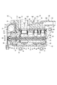
図2および図3に示すように、冷却水制御弁10は、駆動部31、ハウジング32、弁体33、シールユニット34、35、36、保持プレート37、および、パイプ部材38を備えている。
<Cooling water control valve>
Next, the cooling
As shown in FIGS. 2 and 3, the cooling
図3および図4に示すように、駆動部31は、ケース41と、ケース41との間に収容空間を形成しているカバー43と、収容空間に設けられているモータ44および減速機45と、回転角センサ46とを有している。
ケース41は、プレート状のベース部47と、ハウジング32の接続開口部74に嵌合している接続嵌合部42とを有している。接続嵌合部42の中央部には軸挿通孔48および軸受49が設けられている。軸挿通孔48には弁体33の軸部81の一端部が挿通しており、軸受49は軸部81の一端部を支持している。
As shown in FIGS. 3 and 4, the
The
減速機45は、円筒ギア51、第1ギア52、第2ギア53および第3ギア54からなる。円筒ギア51はモータ44の出力軸55に固定されている。第1ギア52は、円筒ギア51と噛み合う第1大径ギア部56、およびそれより小径の第1小径ギア部57を有している。第2ギア53は、第1小径ギア部57と噛み合う第2大径ギア部58、およびそれより小径の第2小径ギア部59を有している。第3ギア54は、第2小径ギア部59と噛み合っており、弁体33の軸部81の一端部に固定されている。減速機45は、モータ44の動力の回転速度を減じて出力する。
The
回転角センサ46は、第3ギア54に設けられている磁石61、62と、それら磁石61、62の間であって弁体33の軸心AX上に設けられている磁気検出部63と、を有している。磁気検出部63は、例えばホールICなどから構成されており、弁体33の回転に伴い変化する磁界を検出することで、弁体33の回転角度を検出する。
The
図2および図3に示すように、ハウジング32は、内部空間75を有する筒状のハウジング本体部71と、エンジン11に固定するための固定用フランジ73と、駆動部31を取り付けるための取付用フランジ72とを有している。ハウジング本体部71の一端部には接続開口部74が形成されている。
ハウジング本体部71は、内部空間75と外部(すなわち、ハウジング32に対する外部)とを接続する入力ポート76および複数の出力ポート77、78、79を有している。第1実施形態では、入力ポート76および出力ポート77、78、79は、ハウジング本体部71の側部に形成されている。
As shown in FIGS. 2 and 3, the
The housing
弁体33は、内部空間75内で軸心AXまわりに回転可能に設けられており、回転位置に応じて入力ポート76と出力ポート77、78、79とをそれぞれ連通または閉塞する。弁体33は、軸部81と、軸部81の外側に設けられている筒部82とを有している。
軸部81は、軸受49およびハウジング本体部71により回転可能に支持されている。筒部82は、軸方向の一端において軸部81に連結されている。軸部81および筒部82は一部材からなる。筒部82と軸部81との間には弁体内流路83が形成されている。
The
The
筒部82は、軸方向に順に並ぶ環状部84、85、86を有している。環状部84は、出力ポート77と同じ軸方向位置に設けられている。環状部85は、出力ポート78と同じ軸方向位置に設けられており、図示しない連結部により環状部84と連結されている。環状部86は、出力ポート79と同じ軸方向位置に設けられており、環状部85と連結されている。環状部84、85、86の外壁面は球面状になっている。
The
筒部82は、弁体33の回転位置に応じて出力ポート77、78、79のいずれか1つと弁体内流路83とを接続する開口部87、88、89と、弁体33の回転位置にかかわらず、内部空間75のうち弁体33の外側(以下、弁体外側空間91)を介して入力ポート76と弁体内流路83とを接続する開口部92とを有している。開口部87は、環状部84に形成されており、出力ポート77と弁体内流路83とを接続可能である。開口部88は、環状部85に形成されており、出力ポート78と弁体内流路83とを接続可能である。開口部89は、環状部86に形成されており、出力ポート79と弁体内流路83とを接続可能である。開口部92は、環状部84と環状部85との間に形成されている。
The
保持プレート37は、シールユニット34、35、36を保持する保持部材であり、プレート部95および保持部96、97、98を有している。プレート部95は、板状であり、ハウジング本体部71に固定されている。保持部96、97、98は、プレート部95から出力ポート77、78、79内にそれぞれ突き出している環状突起である。
The holding
シールユニット34、35、36は、それぞれ出力ポート77、78、79に対応して設けられている。
図3および図5に示すように、シールユニット34は、バルブシール101、スリーブ102、スプリング103およびシール部材104を有している。バルブシール101は、弁体33の環状部84の外壁面に当接している環状シール部材である。スリーブ102は、出力ポート77から弁体外側空間91にかけて設けられている筒状部材であり、バルブシール101を保持している。スプリング103は、スリーブ102を環状部84側に付勢している。シール部材104は、保持プレート37の保持部96とスリーブ102との間をシールしている。
The
As shown in FIGS. 3 and 5, the
シールユニット34は、出力ポート77と弁体外側空間91との間をシールしている。弁体33が回転するとき、環状部84がバルブシール101に対して摺動することでシールユニット34によるシール状態が維持される。
シールユニット35は、シールユニット34と同様のバルブシール、スリーブ、スプリングおよびシール部材を有しており、出力ポート78と弁体外側空間91との間をシールしている。
The
The
シールユニット36は、シールユニット34と同様のバルブシール、スリーブ、スプリングおよびシール部材を有しており、出力ポート79と弁体外側空間91との間をシールしている。
図2および図3に示すように、パイプ部材38は、出力ポート77に接続している流路105をもつパイプ106と、出力ポート78に接続している流路107をもつパイプ108と、出力ポート79に接続している流路109をもつパイプ110とを有している。
The
As shown in FIGS. 2 and 3, the
第1実施形態では、入力ポート76はウォータージャケット21(図1参照)の出口に接続される。パイプ106は循環経路17(図1参照)に接続される。パイプ108は循環経路18(図1参照)に接続される。パイプ110は循環経路19(図1参照)に接続される。
このように構成された冷却水制御弁10において、ウォータージャケット21を流れて温度が上昇した冷却水は、入力ポート76を通じて弁体外側空間91に流入する。弁体外側空間91の冷却水は、弁体33の開口部92を通じて弁体内流路83に流入する。弁体内流路83の冷却水は、出力ポート77、78、79に対する弁体33の開口部87、88、89の開口度合いに応じて、パイプ106、108、110に分配される。
In the first embodiment, the
In the cooling
上記開口度合いは、弁体33の回転位置に応じて変化する。例えば、図3では、開口部87、88、89のいずれも開口度合いが0%となっている。一方、図6では、開口部87、88、89のいずれも開口度合いが100%となっている。冷却水制御弁10は、弁体33の回転位置を図3の状態から図6の状態までの間で変えることで、開口部87、88、89の開口度合いを0%〜100%の間で変化させて、循環経路17、18、19(図1参照)へ流れる冷却水の流量を調整する。
The opening degree changes according to the rotational position of the
<各種ポートおよびその周辺>
次に、各種ポートおよびその周辺についてさらに詳しく説明する。
図7に示すように、入力ポート76は、ハウジング32のうちエンジン11に取り付けられる側、すなわち固定用フランジ73が設けられている側を貫通するように形成されている。そして、入力ポート76は、ハウジング32がエンジン11に取り付けられることによりウォータージャケット21の出口に接続される。そのため、入力ポート76をウォータージャケット21に接続するための配管は特に不要である。
<Various ports and their surroundings>
Next, the various ports and their surroundings will be described in more detail.
As shown in FIG. 7, the
図7に示すように軸方向(軸心AXに平行な方向)から見て、出力ポート77、78、79の少なくとも一部同士が周方向で重なっている。つまり、「一の出力ポートの少なくとも一部は、軸方向から見て他の全ての出力ポートと重なっている」のである。「一の出力ポート」が出力ポート77である場合を例にとると、出力ポート77の少なくとも一部は、軸方向から見て出力ポート78、79と重なっている。これは言い換えれば、図3に示すように軸心AXを含む断面に全ての出力ポート77、78、79が現れるとも言える。
As shown in FIG. 7, when viewed from the axial direction (direction parallel to the axis AX), at least some of the
特に、第1実施形態では、図7に示すように軸方向から見たとき、出力ポート77、78、79の中心軸C1、C2、C3の周方向位置が一致している。また、図8に示すように、出力ポート77、78、79はハウジング32の一側面115に設けられている。また、出力ポート77、78、79は一直線上に並ぶように設けられている。
Particularly, in the first embodiment, when viewed from the axial direction as shown in FIG. 7, the circumferential positions of the central axes C1, C2, C3 of the
図3および図7に示すように、出力ポート77、78、79の開口方向D1、D2、D3(すなわち、中心軸C1、C2、C3に沿う方向)が互いに平行である。一側面115は平面であり、開口方向D1、D2、D3は一側面115に対して垂直な方向である。
As shown in FIGS. 3 and 7, the opening directions D1, D2, D3 of the
図3に示すように、保持プレート37は、全てのシールユニット34、35、36を一括して保持している。保持プレート37はパイプ部材38とは別部材からなる。パイプ部材38は、全てのパイプ106、108、110を一体に成形したものである。
As shown in FIG. 3, the holding
<効果>
以上説明したように、第1実施形態では、一の出力ポート(例えば出力ポート77)の少なくとも一部は、軸方向から見て他の全ての出力ポート(出力ポート78、79)と重なっている。
このように構成することで、出力ポート77、78、79を、ハウジング32のうち弁体33の回転方向における一部分に集結させることができる。そのため、出力ポート77、78、79に接続されるパイプ106、108、110のうち少なくとも根元の部分はハウジング32の幅内に極力収めることができる。したがって、冷却水制御弁10を薄型化することができるとともに、狭小空間に搭載することができる。
<Effect>
As described above, in the first embodiment, at least a part of one output port (for example, the output port 77) overlaps with all other output ports (
With this configuration, the
図9に示すように、エンジン11には、インテークマニホールド121、オルタネータ122、ウォーターポンプ13、コンプレッサ124、スタータ125およびトランスミッション126などが組み付けられている。トランスミッション126にはインバータ127が組み付けられている。第1実施形態の冷却水制御弁10は、エンジン11とインバータ127との間の狭小空間A1に搭載することができる。
As shown in FIG. 9, the
また、第1実施形態では、出力ポート77、78、79はハウジング32の一側面115に設けられている。
これにより、出力ポート77、78、79を、ハウジング32のうち弁体33の回転方向における一部分に集結させることができる。
Further, in the first embodiment, the
As a result, the
また、第1実施形態では、冷却水制御弁10は、出力ポート77、78、79のいずれか1つと弁体外側空間91との間をシールしているシールユニット34、35、36と、出力ポート77、78、79のいずれか1つと接続している流路をもつ複数のパイプ106、108、110とを備える。
これらのシールユニット34、35、36およびパイプ106、108、110は、ハウジング32を回転させることなく組み付けることができる。そのため、組み付け作業が容易になる。
In addition, in the first embodiment, the cooling
The
また、第1実施形態では、出力ポート77、78、79の開口方向D1、D2、D3が互いに平行である。
これにより、シールユニット34、35、36を組み付ける方向が一方向となるので、組み付け作業が容易になる。また、全てのシールユニット34、35、36を同時に組み付けることができる。特に第1実施形態では、保持プレート37が全てのシールユニット34、35、36を一括して保持している。そのため、シールユニット34、35、36と保持プレート37とを事前にサブアッセンブリ化しておき、それをハウジング32に組み付けることで作業効率を高めることができる。
Further, in the first embodiment, the opening directions D1, D2, D3 of the
As a result, the direction in which the
また、保持プレート37は、シールユニット34、35、36を保持するものであって、パイプ部材38とは別部材からなる。
これにより、パイプ部材38を外してもシールユニット34、35、36がハウジング32に組み付いた状態が維持される。また、パイプ部材38とは異なるパイプ部材をもつ他の冷却水制御弁に対して、本実施形態の冷却水制御弁10は、パイプ部材38を取り外した状態の形状を統一することができる。そのため、シールユニット34、35、36の洩れを検査する作業が容易になる。例えば洩れを検査する作業の自動化が容易である。
Further, the holding
As a result, even if the
また、第1実施形態では、パイプ106、108、110は互いに一体に成形されている。
そのため、1回の作業で全てのパイプ106、108、110を組み付けることができ、作業効率を高めることができる。
Further, in the first embodiment, the
Therefore, all the
[第2実施形態]
第2実施形態では、図10に示すように、冷却水制御弁200は、循環経路17、18、19の集合点であって、例えばウォーターポンプ13の手前に設けられている。
図11および図12に示すように、冷却水制御弁200は、第1実施形態における冷却水制御弁10と同様の駆動部31、弁体33、シールユニット34、35、36および保持プレート37を備えている。また、冷却水制御弁200は、第1実施形態におけるハウジング32およびパイプ部材38に代えて、ハウジング201およびパイプ部材202を備えている。
[Second Embodiment]
In the second embodiment, as shown in FIG. 10, the cooling
As shown in FIGS. 11 and 12, the cooling
ハウジング201は、3つの入力ポート203、204、205および1つの出力ポート206を有している。入力ポート203、204、205は、ハウジング201内に冷却水が流入するときの入口となるポートである。入力ポート203、204、205は、第1実施形態における出力ポート77、78、79と位置および形状が同じものである。図13に示すように軸方向(軸心AXに平行な方向)から見て、入力ポート203、204、205の少なくとも一部同士が周方向で重なっている。つまり、一の出力ポート(例えば入力ポート203)の少なくとも一部は、軸方向から見て他の全ての出力ポート(入力ポート204、205)と重なっている。
The
したがって、第1実施形態と同様に、第2実施形態では冷却水制御弁200を薄型化することができるとともに、狭小空間に搭載することができる。
図14に示すように、冷却水制御弁200は、ウォーターポンプ13に隣接する空間であって、オルタネータ122とコンプレッサ124との間の狭小空間A2に搭載することができる。
Therefore, as in the first embodiment, in the second embodiment, the cooling
As shown in FIG. 14, the cooling
ハウジング201は、ハウジング本体部207のうち軸方向で駆動部31とは反対側の端部208に形成された出力ポート206と、端部208に固定された出口パイプ209とを有している。出力ポート206は、弁体33の回転位置にかかわらず内部空間75に連通している。弁体33は、回転位置に応じて出力ポート206と入力ポート203、204、205とをそれぞれ連通または閉塞する。
The
このように1つのポートと複数のポートとの関係が第1実施形態とは逆であってもよい。また、出力ポート206は、必ずしも弁体33の軸方向に垂直な方向に設ける必要はない。そのため、出力ポート206に接続される配管のレイアウトを適宜選択でき、搭載自由度が増す。
また、出力ポート206は、ハウジング201のうち弁体33の軸方向に位置する箇所に設けられている。そのため、入力ポート203、204、205から出力ポート206に至るまでの冷却水の経路の曲がり箇所の数が減るので、通水抵抗を下げることができる。
In this way, the relationship between one port and a plurality of ports may be opposite to that in the first embodiment. Further, the
The
パイプ部材202は、パイプ211、212、213を有している。各パイプ211、212、213は、図11に示すように軸心AXを含み入力ポート203、204、205を通る断面上に位置するように形成されている。パイプ部材202は、ハウジング201の幅以内に収まっている。そのため、冷却水制御弁200を可及的に薄型化することができる。
The
[第3実施形態]
第3実施形態では、図15に示すように、ハウジング221のハウジング本体部222は、出力ポート223、224、225を有している。出力ポート223、224、225の開口方向D1、D2、D3は互いに平行である。出力ポート224は、軸方向から見て出力ポート223と重なっているが、出力ポート225とは重なっていない。
このように、一の出力ポートの少なくとも一部が、軸方向から見て他の出力ポートのいずれか1つ以上と重なっていればよい。それでも、出力ポート223、224、225を、ハウジング221のうち回転方向における一部分に集結させることができ、冷却水制御弁を薄型化することができる。
[Third Embodiment]
In the third embodiment, as shown in FIG. 15, the
Thus, at least a part of one output port may overlap with any one or more of the other output ports when viewed in the axial direction. Nevertheless, the
[第4実施形態]
第4実施形態では、図16に示すように、ハウジング231のハウジング本体部232は、第1側面233および第2側面234を有している。第1側面233および第2側面234は同一平面ではない。
また、ハウジング本体部232は、出力ポート235、236、237を有している。出力ポート235は、第1側面233と第2側面234とに開口している。出力ポート236は第1側面233に開口している。出力ポート237は第2側面234に開口している。このように出力ポートが一側面に設けられなくてもよい。
[Fourth Embodiment]
In the fourth embodiment, as shown in FIG. 16, the
Further, the
出力ポート236は、軸方向から見て出力ポート235と重なっているが、出力ポート237とは重なっていない。このように、一の出力ポートの少なくとも一部が、軸方向から見て他の出力ポートのいずれか1つ以上と重なっていればよい。それでも、出力ポート235、236、237を、ハウジング231のうち回転方向における一部分に集結させることができ、冷却水制御弁を薄型化することができる。
The
出力ポート235、236、237の開口方向D1、D2、D3は、互いに平行ではない。このように、開口方向D1、D2、D3が互いに平行でなくてもよい。それでも、ハウジング231を回転させることなくシールユニットを組み付けることができる。
The opening directions D1, D2, D3 of the
[他の実施形態]
他の実施形態では、冷却水制御弁が適用される冷却装置は、図1または図10に示されるものに限定されない。循環経路に設けられる機器は適宜変更可能である。循環経路は2つまたは4つ以上であってもよい。それに伴い、第2ポート(すなわち弁体の回転位置に応じてハンジング内に対して閉塞されるポート)の数は、2つまたは4つ以上であってもよい。
[Other Embodiments]
In other embodiments, the cooling device to which the cooling water control valve is applied is not limited to that shown in FIG. 1 or 10. The devices provided in the circulation path can be changed as appropriate. There may be two or four or more circulation paths. Accordingly, the number of the second ports (that is, the ports closed in the housing depending on the rotational position of the valve body) may be two or four or more.
他の実施形態では、保持プレートと複数のパイプとが一体に成形されてもよい。
他の実施形態では、駆動部は、他の形式のものであってもよい。要するに、駆動部は回転動力を出力するものであれば、他の公知のものを採用しうる。
他の実施形態では、弁体の軸部および筒部は、別々の部品であってもよい。また、筒部は、複数の環状部同士が別々の部品であってもよい。
本発明は、上述した実施形態に限定されるものではなく、発明の趣旨を逸脱しない範囲で種々の形態で実施可能である。
In other embodiments, the retaining plate and the plurality of pipes may be integrally molded.
In other embodiments, the drive may be of other types. In short, any other known drive unit can be adopted as long as it outputs rotational power.
In other embodiments, the stem and barrel of the valve body may be separate pieces. Further, in the tubular portion, the plurality of annular portions may be separate parts.
The present invention is not limited to the above-described embodiments, and can be implemented in various forms without departing from the spirit of the invention.
32、201、221、231・・・ハウジング
33・・・弁体
75・・・内部空間
76・・・入力ポート(第1ポート)
77、78、79、223、224、225、235、236、237・・・出力ポート(第2ポート)
203、204、205・・・入力ポート(第2ポート)
206・・・出力ポート(第1ポート)
32, 201, 221, 231...
77, 78, 79, 223, 224, 225, 235, 236, 237... Output port (second port)
203, 204, 205... Input port (second port)
206... Output port (first port)
Claims (6)
前記内部空間内で回転可能に設けられており、回転位置に応じて前記第1ポートと複数の前記第2ポートとをそれぞれ連通または閉塞する弁体(33)と、
前記内部空間のうち前記弁体の外側を弁体外側空間(91)とすると、複数の前記第2ポートのいずれか1つと前記弁体外側空間との間をシールしている複数のシールユニット(34、35、36)と、
複数の前記第2ポートのいずれか1つと接続している流路をもつ複数のパイプ(106、108、110)と、
複数の前記シールユニットを保持するものであって、前記パイプとは別部材からなる保持部材(37)と、
を備えており、
前記第1ポートは、前記弁体の回転位置にかかわらず前記内部空間に連通しており、
一の前記第2ポートの少なくとも一部は、前記弁体の軸方向から見て他の前記第2ポートのいずれか1つ以上と重なっており、
前記保持部材は、複数の前記第2ポートのそれぞれに1つずつ設けられた全ての前記シールユニットを一括して保持しているバルブ装置。 A first port (76, 206) and a plurality of second ports (77, 78, 79, 203, 204, 205, 223, 224, 225, 235, 236, 237) that connect the internal space (75) and the outside. A housing (32, 201, 221, 231) having
A valve body (33) that is rotatably provided in the internal space and that communicates or closes the first port and the plurality of second ports in accordance with a rotational position,
If the outer side of the valve body is the valve body outer side space (91) in the inner space, a plurality of seal units that seal between any one of the plurality of second ports and the valve body outer side space ( 34, 35, 36),
A plurality of pipes (106, 108, 110) having a flow path connected to any one of the plurality of second ports;
A holding member (37) for holding a plurality of the seal units, the holding member (37) being a member different from the pipe;
Is equipped with
The first port communicates with the internal space regardless of the rotational position of the valve body,
At least a part of the one second port overlaps with any one or more of the other second ports when viewed from the axial direction of the valve body ,
The said holding member is a valve apparatus which is holding|maintaining all the said sealing units provided one by one to each of the said 2nd port collectively .
Priority Applications (15)
| Application Number | Priority Date | Filing Date | Title |
|---|---|---|---|
| JP2017116601A JP6729500B2 (en) | 2017-06-14 | 2017-06-14 | Valve device |
| CN201880038616.4A CN110753810B (en) | 2017-06-14 | 2018-06-11 | Valve device |
| PCT/JP2018/022205 WO2018230499A1 (en) | 2017-06-14 | 2018-06-11 | Valve device |
| DE112018003065.2T DE112018003065T5 (en) | 2017-06-14 | 2018-06-14 | Valve device |
| PCT/JP2018/022729 WO2018230644A1 (en) | 2017-06-14 | 2018-06-14 | Valve device and method for manufacturing valve |
| CN201880038382.3A CN110730882A (en) | 2017-06-14 | 2018-06-14 | Valve device |
| CN201880038412.0A CN110741192B (en) | 2017-06-14 | 2018-06-14 | Valve device |
| PCT/JP2018/022748 WO2018230652A1 (en) | 2017-06-14 | 2018-06-14 | Valve device |
| PCT/JP2018/022769 WO2018230658A1 (en) | 2017-06-14 | 2018-06-14 | Valve device |
| PCT/JP2018/022803 WO2018230668A1 (en) | 2017-06-14 | 2018-06-14 | Valve device |
| PCT/JP2018/022793 WO2018230664A1 (en) | 2017-06-14 | 2018-06-14 | Valve device |
| PCT/JP2018/022783 WO2018230661A1 (en) | 2017-06-14 | 2018-06-14 | Valve device |
| US16/710,353 US11085548B2 (en) | 2017-06-14 | 2019-12-11 | Valve device |
| US16/710,315 US11274753B2 (en) | 2017-06-14 | 2019-12-11 | Valve device |
| US16/711,779 US11285778B2 (en) | 2017-06-14 | 2019-12-12 | Valve device |
Applications Claiming Priority (1)
| Application Number | Priority Date | Filing Date | Title |
|---|---|---|---|
| JP2017116601A JP6729500B2 (en) | 2017-06-14 | 2017-06-14 | Valve device |
Publications (3)
| Publication Number | Publication Date |
|---|---|
| JP2019002454A JP2019002454A (en) | 2019-01-10 |
| JP2019002454A5 JP2019002454A5 (en) | 2019-09-26 |
| JP6729500B2 true JP6729500B2 (en) | 2020-07-22 |
Family
ID=64660126
Family Applications (1)
| Application Number | Title | Priority Date | Filing Date |
|---|---|---|---|
| JP2017116601A Active JP6729500B2 (en) | 2017-06-14 | 2017-06-14 | Valve device |
Country Status (4)
| Country | Link |
|---|---|
| US (1) | US11085548B2 (en) |
| JP (1) | JP6729500B2 (en) |
| CN (1) | CN110753810B (en) |
| WO (1) | WO2018230499A1 (en) |
Families Citing this family (8)
| Publication number | Priority date | Publication date | Assignee | Title |
|---|---|---|---|---|
| CN110741192B (en) | 2017-06-14 | 2022-03-22 | 株式会社电装 | Valve device |
| US11285778B2 (en) | 2017-06-14 | 2022-03-29 | Denso Corporation | Valve device |
| JP6708178B2 (en) | 2017-07-24 | 2020-06-10 | 株式会社デンソー | Valve device and cooling system |
| CN115355336A (en) | 2018-05-31 | 2022-11-18 | 株式会社电装 | Valve device |
| JP7192467B2 (en) | 2018-05-31 | 2022-12-20 | 株式会社デンソー | valve device |
| JP7331646B2 (en) | 2019-11-07 | 2023-08-23 | 株式会社デンソー | valve device |
| JP7434814B2 (en) | 2019-11-07 | 2024-02-21 | 株式会社デンソー | valve device |
| US20230220918A1 (en) * | 2022-01-13 | 2023-07-13 | Illinois Tool Works Inc. | Multi-Passage Valve |
Family Cites Families (13)
| Publication number | Priority date | Publication date | Assignee | Title |
|---|---|---|---|---|
| JPS5925751U (en) * | 1982-08-10 | 1984-02-17 | 株式会社永田製作所 | Rotary operation valve for simultaneous opening/closing or switching opening/closing of multiple passages |
| JPH08338544A (en) * | 1995-06-14 | 1996-12-24 | Asahi Eitou Kk | Flow passage switch |
| JPH1182769A (en) * | 1997-09-05 | 1999-03-26 | Fuji Koki Corp | Four-way control valve |
| ATE505682T1 (en) * | 2005-09-16 | 2011-04-15 | Tongaat Hulett Ltd | INDEXING ARRANGEMENT |
| US8753430B2 (en) * | 2011-05-10 | 2014-06-17 | Uop Llc | Affixing a seal sheet to a rotor of a rotary valve |
| US9670825B2 (en) * | 2013-03-21 | 2017-06-06 | Hitachi Automotive Systems, Ltd. | Flow rate-controlling valve |
| JP6175291B2 (en) * | 2013-06-14 | 2017-08-02 | Ckd株式会社 | Gasket mounting structure |
| CN106232960B (en) * | 2014-04-25 | 2018-11-16 | 日立汽车系统株式会社 | Cooling controller, flow control valve and cooling control method |
| JP2016031139A (en) * | 2014-07-30 | 2016-03-07 | アイシン精機株式会社 | Fluid control valve |
| JP6645739B2 (en) * | 2015-01-28 | 2020-02-14 | 本田技研工業株式会社 | Integrated unit |
| EP3073161B1 (en) * | 2015-03-25 | 2018-08-01 | Magna Powertrain Inc. | Multiport valve with modular rotor |
| CN107614949B (en) * | 2015-06-05 | 2020-02-07 | 日立汽车系统株式会社 | Flow control valve |
| JP6708178B2 (en) | 2017-07-24 | 2020-06-10 | 株式会社デンソー | Valve device and cooling system |
-
2017
- 2017-06-14 JP JP2017116601A patent/JP6729500B2/en active Active
-
2018
- 2018-06-11 CN CN201880038616.4A patent/CN110753810B/en active Active
- 2018-06-11 WO PCT/JP2018/022205 patent/WO2018230499A1/en active Application Filing
-
2019
- 2019-12-11 US US16/710,353 patent/US11085548B2/en active Active
Also Published As
| Publication number | Publication date |
|---|---|
| CN110753810A (en) | 2020-02-04 |
| JP2019002454A (en) | 2019-01-10 |
| WO2018230499A1 (en) | 2018-12-20 |
| CN110753810B (en) | 2021-10-29 |
| US20200109788A1 (en) | 2020-04-09 |
| US11085548B2 (en) | 2021-08-10 |
Similar Documents
| Publication | Publication Date | Title |
|---|---|---|
| JP6729500B2 (en) | Valve device | |
| JP6724874B2 (en) | Valve device and cooling system | |
| JP6708178B2 (en) | Valve device and cooling system | |
| JP6775466B2 (en) | Flow control valve | |
| JP6846076B2 (en) | Flow control valve and cooling system | |
| CN108005774B (en) | Control valve | |
| US10626999B2 (en) | Control valve | |
| CN107614949B (en) | Flow control valve | |
| US10508748B2 (en) | Control valve | |
| JP2018071779A (en) | Control valve | |
| CN104471296A (en) | Rotary valve | |
| WO2018230644A1 (en) | Valve device and method for manufacturing valve | |
| WO2018230658A1 (en) | Valve device | |
| WO2018230668A1 (en) | Valve device | |
| JP7331646B2 (en) | valve device | |
| JP7434814B2 (en) | valve device | |
| JP7393466B2 (en) | Valve gear and cooling system | |
| JP2019157905A (en) | Control valve | |
| JP7419752B2 (en) | valve device | |
| WO2018230661A1 (en) | Valve device | |
| JP2018194167A (en) | Control valve | |
| JP2023074373A (en) | Internal combustion engine and liquid circulation system | |
| JP2019211064A (en) | Valve device | |
| JP2007303327A (en) | Intake flow control valve device |
Legal Events
| Date | Code | Title | Description |
|---|---|---|---|
| A521 | Request for written amendment filed |
Free format text: JAPANESE INTERMEDIATE CODE: A523 Effective date: 20190808 |
|
| A621 | Written request for application examination |
Free format text: JAPANESE INTERMEDIATE CODE: A621 Effective date: 20190808 |
|
| TRDD | Decision of grant or rejection written | ||
| A01 | Written decision to grant a patent or to grant a registration (utility model) |
Free format text: JAPANESE INTERMEDIATE CODE: A01 Effective date: 20200602 |
|
| A61 | First payment of annual fees (during grant procedure) |
Free format text: JAPANESE INTERMEDIATE CODE: A61 Effective date: 20200615 |
|
| R151 | Written notification of patent or utility model registration |
Ref document number: 6729500 Country of ref document: JP Free format text: JAPANESE INTERMEDIATE CODE: R151 |
|
| R250 | Receipt of annual fees |
Free format text: JAPANESE INTERMEDIATE CODE: R250 |