JP6571005B2 - Operation device for medical equipment - Google Patents
Operation device for medical equipmentInfo
- Publication number
- JP6571005B2 JP6571005B2 JP2015549895A JP2015549895A JP6571005B2 JP 6571005 B2 JP6571005 B2 JP 6571005B2 JP 2015549895 A JP2015549895 A JP 2015549895A JP 2015549895 A JP2015549895 A JP 2015549895A JP 6571005 B2 JP6571005 B2 JP 6571005B2
- Authority
- JP
- Japan
- Prior art keywords
- signal
- ring
- processing
- shaped magnet
- sensor
- Prior art date
- Legal status (The legal status is an assumption and is not a legal conclusion. Google has not performed a legal analysis and makes no representation as to the accuracy of the status listed.)
- Active
Links
Images


Classifications
-
- A—HUMAN NECESSITIES
- A61—MEDICAL OR VETERINARY SCIENCE; HYGIENE
- A61B—DIAGNOSIS; SURGERY; IDENTIFICATION
- A61B1/00—Instruments for performing medical examinations of the interior of cavities or tubes of the body by visual or photographical inspection, e.g. endoscopes; Illuminating arrangements therefor
- A61B1/00002—Operational features of endoscopes
- A61B1/00039—Operational features of endoscopes provided with input arrangements for the user
- A61B1/00042—Operational features of endoscopes provided with input arrangements for the user for mechanical operation
-
- A—HUMAN NECESSITIES
- A61—MEDICAL OR VETERINARY SCIENCE; HYGIENE
- A61B—DIAGNOSIS; SURGERY; IDENTIFICATION
- A61B1/00—Instruments for performing medical examinations of the interior of cavities or tubes of the body by visual or photographical inspection, e.g. endoscopes; Illuminating arrangements therefor
- A61B1/00002—Operational features of endoscopes
- A61B1/00004—Operational features of endoscopes characterised by electronic signal processing
- A61B1/00006—Operational features of endoscopes characterised by electronic signal processing of control signals
-
- A—HUMAN NECESSITIES
- A61—MEDICAL OR VETERINARY SCIENCE; HYGIENE
- A61B—DIAGNOSIS; SURGERY; IDENTIFICATION
- A61B1/00—Instruments for performing medical examinations of the interior of cavities or tubes of the body by visual or photographical inspection, e.g. endoscopes; Illuminating arrangements therefor
- A61B1/00002—Operational features of endoscopes
- A61B1/00004—Operational features of endoscopes characterised by electronic signal processing
- A61B1/00009—Operational features of endoscopes characterised by electronic signal processing of image signals during a use of endoscope
-
- A—HUMAN NECESSITIES
- A61—MEDICAL OR VETERINARY SCIENCE; HYGIENE
- A61B—DIAGNOSIS; SURGERY; IDENTIFICATION
- A61B1/00—Instruments for performing medical examinations of the interior of cavities or tubes of the body by visual or photographical inspection, e.g. endoscopes; Illuminating arrangements therefor
- A61B1/00064—Constructional details of the endoscope body
- A61B1/00066—Proximal part of endoscope body, e.g. handles
-
- A—HUMAN NECESSITIES
- A61—MEDICAL OR VETERINARY SCIENCE; HYGIENE
- A61B—DIAGNOSIS; SURGERY; IDENTIFICATION
- A61B1/00—Instruments for performing medical examinations of the interior of cavities or tubes of the body by visual or photographical inspection, e.g. endoscopes; Illuminating arrangements therefor
- A61B1/00064—Constructional details of the endoscope body
- A61B1/00105—Constructional details of the endoscope body characterised by modular construction
-
- A—HUMAN NECESSITIES
- A61—MEDICAL OR VETERINARY SCIENCE; HYGIENE
- A61B—DIAGNOSIS; SURGERY; IDENTIFICATION
- A61B1/00—Instruments for performing medical examinations of the interior of cavities or tubes of the body by visual or photographical inspection, e.g. endoscopes; Illuminating arrangements therefor
- A61B1/00112—Connection or coupling means
- A61B1/00121—Connectors, fasteners and adapters, e.g. on the endoscope handle
- A61B1/00124—Connectors, fasteners and adapters, e.g. on the endoscope handle electrical, e.g. electrical plug-and-socket connection
-
- A—HUMAN NECESSITIES
- A61—MEDICAL OR VETERINARY SCIENCE; HYGIENE
- A61B—DIAGNOSIS; SURGERY; IDENTIFICATION
- A61B1/00—Instruments for performing medical examinations of the interior of cavities or tubes of the body by visual or photographical inspection, e.g. endoscopes; Illuminating arrangements therefor
- A61B1/00147—Holding or positioning arrangements
- A61B1/00158—Holding or positioning arrangements using magnetic field
-
- A—HUMAN NECESSITIES
- A61—MEDICAL OR VETERINARY SCIENCE; HYGIENE
- A61B—DIAGNOSIS; SURGERY; IDENTIFICATION
- A61B1/00—Instruments for performing medical examinations of the interior of cavities or tubes of the body by visual or photographical inspection, e.g. endoscopes; Illuminating arrangements therefor
- A61B1/00163—Optical arrangements
- A61B1/00188—Optical arrangements with focusing or zooming features
-
- A—HUMAN NECESSITIES
- A61—MEDICAL OR VETERINARY SCIENCE; HYGIENE
- A61B—DIAGNOSIS; SURGERY; IDENTIFICATION
- A61B1/00—Instruments for performing medical examinations of the interior of cavities or tubes of the body by visual or photographical inspection, e.g. endoscopes; Illuminating arrangements therefor
- A61B1/04—Instruments for performing medical examinations of the interior of cavities or tubes of the body by visual or photographical inspection, e.g. endoscopes; Illuminating arrangements therefor combined with photographic or television appliances
- A61B1/045—Control thereof
-
- A—HUMAN NECESSITIES
- A61—MEDICAL OR VETERINARY SCIENCE; HYGIENE
- A61B—DIAGNOSIS; SURGERY; IDENTIFICATION
- A61B17/00—Surgical instruments, devices or methods, e.g. tourniquets
- A61B17/00234—Surgical instruments, devices or methods, e.g. tourniquets for minimally invasive surgery
-
- A—HUMAN NECESSITIES
- A61—MEDICAL OR VETERINARY SCIENCE; HYGIENE
- A61B—DIAGNOSIS; SURGERY; IDENTIFICATION
- A61B5/00—Measuring for diagnostic purposes; Identification of persons
- A61B5/05—Detecting, measuring or recording for diagnosis by means of electric currents or magnetic fields; Measuring using microwaves or radio waves
-
- A—HUMAN NECESSITIES
- A61—MEDICAL OR VETERINARY SCIENCE; HYGIENE
- A61B—DIAGNOSIS; SURGERY; IDENTIFICATION
- A61B5/00—Measuring for diagnostic purposes; Identification of persons
- A61B5/06—Devices, other than using radiation, for detecting or locating foreign bodies ; determining position of probes within or on the body of the patient
- A61B5/061—Determining position of a probe within the body employing means separate from the probe, e.g. sensing internal probe position employing impedance electrodes on the surface of the body
- A61B5/062—Determining position of a probe within the body employing means separate from the probe, e.g. sensing internal probe position employing impedance electrodes on the surface of the body using magnetic field
-
- A—HUMAN NECESSITIES
- A61—MEDICAL OR VETERINARY SCIENCE; HYGIENE
- A61B—DIAGNOSIS; SURGERY; IDENTIFICATION
- A61B5/00—Measuring for diagnostic purposes; Identification of persons
- A61B5/74—Details of notification to user or communication with user or patient ; user input means
- A61B5/7475—User input or interface means, e.g. keyboard, pointing device, joystick
-
- G—PHYSICS
- G01—MEASURING; TESTING
- G01D—MEASURING NOT SPECIALLY ADAPTED FOR A SPECIFIC VARIABLE; ARRANGEMENTS FOR MEASURING TWO OR MORE VARIABLES NOT COVERED IN A SINGLE OTHER SUBCLASS; TARIFF METERING APPARATUS; MEASURING OR TESTING NOT OTHERWISE PROVIDED FOR
- G01D5/00—Mechanical means for transferring the output of a sensing member; Means for converting the output of a sensing member to another variable where the form or nature of the sensing member does not constrain the means for converting; Transducers not specially adapted for a specific variable
- G01D5/12—Mechanical means for transferring the output of a sensing member; Means for converting the output of a sensing member to another variable where the form or nature of the sensing member does not constrain the means for converting; Transducers not specially adapted for a specific variable using electric or magnetic means
- G01D5/244—Mechanical means for transferring the output of a sensing member; Means for converting the output of a sensing member to another variable where the form or nature of the sensing member does not constrain the means for converting; Transducers not specially adapted for a specific variable using electric or magnetic means influencing characteristics of pulses or pulse trains; generating pulses or pulse trains
- G01D5/245—Mechanical means for transferring the output of a sensing member; Means for converting the output of a sensing member to another variable where the form or nature of the sensing member does not constrain the means for converting; Transducers not specially adapted for a specific variable using electric or magnetic means influencing characteristics of pulses or pulse trains; generating pulses or pulse trains using a variable number of pulses in a train
- G01D5/2451—Incremental encoders
-
- G—PHYSICS
- G06—COMPUTING; CALCULATING OR COUNTING
- G06F—ELECTRIC DIGITAL DATA PROCESSING
- G06F3/00—Input arrangements for transferring data to be processed into a form capable of being handled by the computer; Output arrangements for transferring data from processing unit to output unit, e.g. interface arrangements
- G06F3/01—Input arrangements or combined input and output arrangements for interaction between user and computer
- G06F3/03—Arrangements for converting the position or the displacement of a member into a coded form
- G06F3/033—Pointing devices displaced or positioned by the user, e.g. mice, trackballs, pens or joysticks; Accessories therefor
- G06F3/0362—Pointing devices displaced or positioned by the user, e.g. mice, trackballs, pens or joysticks; Accessories therefor with detection of 1D translations or rotations of an operating part of the device, e.g. scroll wheels, sliders, knobs, rollers or belts
-
- A—HUMAN NECESSITIES
- A61—MEDICAL OR VETERINARY SCIENCE; HYGIENE
- A61B—DIAGNOSIS; SURGERY; IDENTIFICATION
- A61B2562/00—Details of sensors; Constructional details of sensor housings or probes; Accessories for sensors
- A61B2562/02—Details of sensors specially adapted for in-vivo measurements
- A61B2562/0223—Magnetic field sensors
Description
本開示は、医療機器用の操作装置に関する。 The present disclosure relates to an operating device for a medical device.
医療機器用の操作装置として、例えば、磁気を利用した、医療用の撮像装置の手動制御や調整を行うための操作装置がある。また、磁気を利用した操作装置が開発されている。磁気を利用した操作装置に係る技術としては、例えば下記の特許文献1、2に記載の技術が挙げられる。 As an operation apparatus for medical equipment, for example, there is an operation apparatus for performing manual control and adjustment of a medical imaging apparatus using magnetism. In addition, an operation device using magnetism has been developed. Examples of the technique related to the operating device using magnetism include the techniques described in
既存の磁気を利用した医療用の操作装置(以下、「既存の操作装置」と示す。)では、例えば、“磁気吸引力を用いて内部の部材を動かす”、“磁気センサが磁界の中に存在するか否かを感知する”という手法が用いられている。しかしながら、既存の操作装置を用いたとしても、ユーザ操作に応じた精緻な制御や調整を実現することが困難であり、ユーザ操作に応じた処理を行わせることが可能な操作装置が求められている。 In a medical operation device using existing magnetism (hereinafter referred to as “existing operation device”), for example, “moving an internal member using magnetic attraction force”, “magnetic sensor is in a magnetic field. A method of “detecting whether or not it exists” is used. However, even if an existing operation device is used, it is difficult to realize precise control and adjustment according to user operation, and an operation device capable of performing processing according to user operation is required. Yes.
本開示では、ユーザ操作に応じた処理を行わせることが可能な、新規かつ改良された医療機器用の操作装置を提案する。 The present disclosure proposes a new and improved operating device for medical devices that can perform processing according to a user operation.
本開示によれば、円周方向、または径方向に着磁され、ユーザの回転操作に応じて回転するリング状の磁石と、磁界を検出し、検出される磁界に応じた信号を出力するセンサ部と、を備え、上記センサ部は、位相が異なる2相の信号を出力する、医療機器用の操作装置が提供される。 According to the present disclosure, a ring-shaped magnet that is magnetized in a circumferential direction or a radial direction and rotates according to a user's rotation operation, and a sensor that detects a magnetic field and outputs a signal corresponding to the detected magnetic field. An operation device for a medical device is provided, wherein the sensor unit outputs two-phase signals having different phases.
本開示によれば、ユーザ操作に応じた処理を行わせることができる。 According to this indication, processing according to user operation can be performed.
なお、上記の効果は必ずしも限定的なものではなく、上記の効果とともに、または上記の効果に代えて、本明細書に示されたいずれかの効果、または本明細書から把握されうる他の効果が奏されてもよい。 Note that the above effects are not necessarily limited, and any of the effects shown in the present specification, or other effects that can be grasped from the present specification, together with or in place of the above effects. May be played.
以下に添付図面を参照しながら、本開示の好適な実施の形態について詳細に説明する。なお、本明細書及び図面において、実質的に同一の機能構成を有する構成要素については、同一の符号を付することにより重複説明を省略する。 Hereinafter, preferred embodiments of the present disclosure will be described in detail with reference to the accompanying drawings. In addition, in this specification and drawing, about the component which has the substantially same function structure, duplication description is abbreviate | omitted by attaching | subjecting the same code | symbol.
また、以下では、下記に示す順序で説明を行う。
1.本実施形態に係る操作装置
2.本実施形態に係るプログラムIn the following, description will be given in the following order.
1. 1. Operation device according to the present embodiment Program according to this embodiment
(本実施形態に係る操作装置)
本実施形態に係る操作装置は、ユーザの回転操作に応じた、位相が異なる2相の信号を出力することによって、ユーザ操作に応じた処理を行わせる。(Operation device according to this embodiment)
The operation device according to the present embodiment outputs a two-phase signal having different phases according to the rotation operation of the user, thereby performing a process according to the user operation.
ここで、本実施形態に係る操作装置が、2相の信号に基づきユーザ操作に応じた処理を行わせる対象としては、例えば、本実施形態に係る操作装置が備える処理部(後述する)や、当該処理部と同様の機能を有する外部の処理装置が挙げられる。本実施形態に係る処理部(後述する)などにおける、2相の信号に基づく処理の一例については、後述する。 Here, as a target for the operation device according to the present embodiment to perform processing according to a user operation based on a two-phase signal, for example, a processing unit (described later) included in the operation device according to the present embodiment, An external processing device having the same function as that of the processing unit can be used. An example of processing based on a two-phase signal in a processing unit (described later) according to the present embodiment will be described later.
以下、本実施形態に係る操作装置が、医療用の内視鏡に適用される場合を例に挙げて、本実施形態に係る操作装置の構成、処理について説明する。なお、本実施形態に係る操作装置が適用される医療用の機器は、内視鏡に限られない。本実施形態に係る操作装置は、後述する機構によりユーザ操作に応じた処理を行わせることが可能な、任意の医療用の機器に適用することが可能である。 Hereinafter, the configuration and processing of the operating device according to the present embodiment will be described by taking as an example the case where the operating device according to the present embodiment is applied to a medical endoscope. The medical device to which the operation device according to the present embodiment is applied is not limited to an endoscope. The operation device according to the present embodiment can be applied to any medical device that can cause a process according to a user operation to be performed by a mechanism described later.
図1は、本実施形態に係る操作装置100の一例を説明するための説明図である。図1に示す操作装置100は、医療用の内視鏡に適用された操作装置(医療用の内視鏡の制御や調整に用いられる操作装置)を示している。 FIG. 1 is an explanatory diagram for explaining an example of the
操作装置100は、例えば、ユーザが回転操作を行うことが可能な操作リング102を含む。操作リング102は、時計回り方向、または反時計回り方向に、自由に回転する。操作装置100を用いるユーザは、操作リング102を操作することによって、時計回り方向、または反時計回り方向に、所望の回転操作を行うことができる。操作リング102に対するユーザの回転操作が行われると、操作装置100は、操作リング102に対する回転操作に応じた2相の信号を出力することによって、ユーザ操作に応じた処理を行わせる。 The
ここで、操作リング102に対する回転操作に応じた処理としては、例えば、下記に示すような回転方向に応じたフォーカス(ピント合わせ)に係る処理が挙げられる。回転操作に応じた処理が、回転方向に応じたフォーカスに係る処理である場合、操作リング102は、いわゆるフォーカスリングの役目を果たす。
・回転方向が(術者側(内視鏡)から患者側を見て)時計回りである場合:ピントが手前に近づく
・回転方向が(術者側(内視鏡)から患者側を見て)反時計回りである場合:ピントが奥に遠ざかる
Here, as a process according to the rotation operation with respect to the
・ When the direction of rotation is clockwise (looking from the operator side (endoscope) to the patient side): Focus approaches the front ・ The direction of rotation (from the operator side (endoscope) to the patient side) ) If it is anti-clockwise: the focus moves away in the back
また、操作リング102に対する回転操作により、一定以上の回転速度が検出された場合、フォーカスに係る処理などの行われている処理のキャンセルや、予め設定されている処理が行われてもよい。 Further, when a rotation speed of a certain level or more is detected by a rotation operation on the
なお、操作リング102に対する回転操作に応じた処理の例が、上記に示す例に限られないことは、言うまでもない。 Needless to say, the example of processing according to the rotation operation on the
また、操作リング102は、上記のように自由に回転することが可能であるが、回転操作に応じた処理には、操作リング102の駆動範囲に対応する上限と下限とが設けられていてもよい。駆動範囲に対応する上限と下限とが設けられることによって、例えば、“駆動範囲に対応する上限または下限を超えたときには、例えば、操作リング102は回転するが、フォーカスに係る処理(回転操作に応じた処理の一例)では、ピント位置を、上限または下限に対応するピント位置から変化させないこと”が実現される。 Further, the
また、操作リング102に対する回転操作が行われたときに、当該回転操作に応じた処理以外の他の処理や制御が行われている場合には、当該他の処理や制御よりも、当該回転操作に応じた処理が優先して行われてもよい。例えば、AF(Auto Focus)制御が行われている最中に、ユーザが操作リング102を用いた回転操作を行った場合には、AF制御からMF(Manual Focus)制御へと切り替わり、操作リング102の回転方向に応じたフォーカスに係る処理(回転操作に応じた処理の一例)が行われる。上記のように、操作リング102に対する回転操作に応じた処理が他の処理や制御よりも優先的に行われることによって、ユーザは、例えば、AF制御中であっても、操作リング102を用いた操作によってピントの微調整を手動で行うことができる。
In addition, when a rotation operation is performed on the
また、回転操作に応じた処理が、回転方向に応じたフォーカスに係る処理であるときに、ユーザが操作リング102を用いたピント合わせを行う場合(いわゆる、MFモードである場合)において、ユーザのリセット操作などによってリセットがされたときには、例えば、最後に操作されたピント位置からフォーカスに係る処理が行われる。一方、自動的にピント合わせが行われる場合(いわゆる、AFモードである場合)において、ユーザのリセット操作などによってリセットがされたときには、例えば、AF制御によりピントがあった位置が、ピント位置を調整する際の起点となる。なお、リセットがされた場合におけるピント位置を調整する際の起点となるピント位置が、上記に示す例に限られないことは、言うまでもない。 When the process according to the rotation operation is a process related to the focus according to the rotation direction, when the user performs focusing using the operation ring 102 (in the so-called MF mode), the user's When the reset is performed by a reset operation or the like, for example, a process related to the focus is performed from the focus position operated last. On the other hand, when the focus is automatically performed (in the so-called AF mode), when the reset is performed by the user's reset operation or the like, for example, the focus position is adjusted by the AF control. It becomes the starting point when doing. Needless to say, the focus position that is the starting point for adjusting the focus position when the reset is performed is not limited to the example shown above.
[1]本実施形態に係る2相の信号の出力に係る構成
[1−1]ユーザの回転操作を検出することが可能な構成の一例
本実施形態に係る2相の信号の出力に係る構成について説明する前に、ユーザの回転操作を検出することが可能な構成の一例について説明する。[1] Configuration related to output of two-phase signal according to this embodiment [1-1] Example of configuration capable of detecting user's rotation operation Configuration related to output of two-phase signal according to this embodiment An example of a configuration that can detect a user's rotation operation will be described.
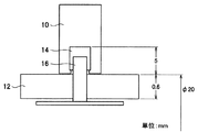
図2は、ユーザの回転操作を検出することが可能な構成を有する操作装置の一例を説明するための説明図であり、PI(Photo Interrupter)/PR(Photo Reflector)方式に係る構成を示している。 FIG. 2 is an explanatory diagram for explaining an example of an operation device having a configuration capable of detecting a user's rotation operation, and shows a configuration related to a PI (Photo Interrupter) / PR (Photo Reflector) system. Yes.
PI/PR方式に係る構成を有する操作装置は、例えば、操作リング10と、外装部品12と、櫛歯形状部材14と、PIセンサ(PRセンサ)16とを備える。 An operation device having a configuration related to the PI / PR system includes, for example, an
PI/PR方式に係る構成を有する操作装置では、操作リング10の回転に応じてPIセンサ(PRセンサ)16により検出される櫛歯に応じたパルス信号が、ユーザの回転操作に応じた信号として用いられる。 In the operating device having a configuration related to the PI / PR method, a pulse signal corresponding to the comb teeth detected by the PI sensor (PR sensor) 16 according to the rotation of the
ここで、医療用の内視鏡などの医療用の機器では、使用後に140[℃]程度の環境下でオートクレーブ滅菌(高温高圧蒸気滅菌)が行われる。そのため、医療用の機器では、オートクレーブ滅菌に対する耐久性を有することが求められている。例えば医療用の内視鏡にオートクレーブ滅菌に対する耐久性を持たせる場合には、レンズユニット(後述する)などを、気密性、防水性が高い密閉構造内に配置する対応がとられる。レンズユニット(後述する)などを、密閉構造内に配置することによって、オートクレーブ滅菌による蒸気の流入が防止され、レンズユニット(後述する)などがオートクレーブ滅菌が行われることにより破損することが防止される。 Here, in a medical device such as a medical endoscope, autoclave sterilization (high-temperature high-pressure steam sterilization) is performed in an environment of about 140 [° C.] after use. Therefore, medical devices are required to have durability against autoclave sterilization. For example, when a medical endoscope is provided with durability against autoclave sterilization, a lens unit (described later) and the like are arranged in a sealed structure with high airtightness and waterproofness. By disposing a lens unit (described later) in a sealed structure, inflow of steam due to autoclave sterilization is prevented, and the lens unit (described later) is prevented from being damaged by autoclave sterilization. .
しかしながら、PI/PR方式が用いられる場合には、図2に示すように、外装部品12に穴を空ける必要があるので、PI/PR方式が用いられる場合には、上記に示すようなオートクレーブ滅菌に対する耐久性は望めない。よって、PI/PR方式に係る構成を有する操作装置を、医療用の機器に適用することは、望ましくない。 However, when the PI / PR method is used, it is necessary to make a hole in the
また、PI/PR方式が用いられる場合には、図2に示すように、櫛歯形状部材14を設ける必要があるので、小型化にも不利である。 When the PI / PR method is used, it is necessary to provide the comb-shaped
図3は、ユーザの回転操作を検出することが可能な構成を有する操作装置の他の例を説明するための説明図であり、可変抵抗方式に係る構成を示している。 FIG. 3 is an explanatory diagram for explaining another example of the operation device having a configuration capable of detecting a user's rotation operation, and shows a configuration related to a variable resistance method.
可変抵抗方式に係る構成を有する操作装置は、例えば、操作リング20と、外装部品22と、N極の磁石24Aと、S極の磁石24Bと、摺動子26と、可変抵抗28とを備える。N極の磁石24Aと、S極の磁石24Bとは、磁界を遮断しない外装部品22により隔てられる。 The operating device having the configuration related to the variable resistance system includes, for example, an
可変抵抗方式に係る構成を有する操作装置では、操作リング20の回転に応じてN極の磁石24Aが移動し、磁気吸引力によってS極の磁石24Bが移動し、摺動子26が、S極の磁石24Bと共に移動する。可変抵抗28の抵抗値は、摺動子26の位置によって変わり、可変抵抗方式に係る構成を有する操作装置では、摺動子26の位置、すなわち可変抵抗28の抵抗値に応じた信号が、ユーザの回転操作に応じた信号として用いられる。 In the operating device having the configuration related to the variable resistance method, the N-
ここで、可変抵抗方式が用いられる場合には、長さが有限である可変抵抗において、操作の検出に係る分解能を満たす必要がある。しかしながら、可変抵抗方式が用いられる場合には、メカ設計で工夫を凝らしたとしても、操作の検出に係る分解能を、フォーカスの調整などに用いることができる程、小さくすることは困難である。 Here, when the variable resistance method is used, it is necessary to satisfy the resolution related to the detection of the operation in the variable resistance having a finite length. However, when the variable resistance method is used, it is difficult to reduce the resolution relating to the detection of the operation to such an extent that it can be used for focus adjustment even if the device is devised by mechanical design.
[1−2]本実施形態に係る2相の信号の出力に係る構成
図4は、本実施形態に係る操作装置100における2相の信号の出力に係る構成の一例を示す説明図である。図4に示すAは、例えば、図1に示す操作装置100の操作リング102部分における、図1における奥行方向の断面を概略的に示している。また、図4に示すBは、例えば、図1に示す操作装置100の操作リング102部分における、図1における垂直方向の断面の一部を概略的に示している。[1-2] Configuration Related to Output of Two-Phase Signal According to this Embodiment FIG. 4 is an explanatory diagram illustrating an example of a configuration related to output of a two-phase signal in the
操作装置100は、例えば、リング状の磁石104と、センサ部106とを備える。 The operating
リング状の磁石104は、N極の磁石とS極の磁石とがリングの円周方向に交互に配置され、ユーザの回転操作に応じて回転する。つまり、リング状の磁石104は、多極に着磁されている、リング状の磁石である。図4の例では、リング状の磁石104は、操作リング102に対するユーザの回転操作によって、操作リング102と共に移動する。 In the ring-shaped
センサ部106は、磁界を検出し、検出される磁界に応じた信号を出力する。また、センサ部106は、位相が異なる2相の信号を出力する。ここで、センサ部106は、例えば図4に示すように、リング状の磁石104と接しないように配置され、リング状の磁石104の磁力により移動しない。 The
より具体的には、センサ部106は、例えば、2相の信号を出力する1つのセンサで構成される。また、センサ部106は、2相の信号のうちの一方の信号(以下、「A相の信号」、または単に「A相」と示す場合がある。)を出力するセンサと、2相の信号のうちの他方の信号(以下、「B相の信号」、または単に「B相」と示す場合がある。)を出力するセンサとの2つのセンサで構成される。 More specifically, the
以下では、センサ部106が、A相の信号を出力するセンサと、B相の信号を出力するセンサとの2つのセンサで構成される場合を例に挙げる。なお、センサ部106が、2相の信号を出力する1つのセンサで構成される場合は、当該センサは、A相の信号を出力するセンサおよびB相の信号を出力するセンサの機能を有していることに相当する。よって、センサ部106が、2相の信号を出力する1つのセンサで構成される場合であっても、センサ部106から出力される2相の信号は、下記に示す例と同様である。
In the following, the
センサ部106を構成するセンサとしては、例えば、ホールセンサが挙げられる。なお、センサ部106を構成するセンサは、リング状の磁石104と接しない状態で、リング状の磁石104が発生させる磁界を検出することが可能な、任意の方式のセンサであってもよい。 An example of the sensor constituting the
また、センサ部106は、例えばコンパレータ(図示せず)を有し、ホールセンサから出力される、検出された磁界に応じたアナログ信号を、ハイレベルの信号またはローレベルの信号という検出された磁界に対応する信号レベルの信号(デジタル信号)に変換して、当該検出された磁界に対応する信号レベルの信号を出力する。ここで、リング状の磁石104が、図4のAに示すようにN極の磁石とS極の磁石とが円周方向に交互に配置される構成である場合には、センサ部106は、磁極に応じた信号レベルの信号(デジタル信号)を出力する。センサ部106は、例えばラッチ回路(図示せず)をさらに備えていてもよい。 The
なお、本実施形態に係るセンサ部106の構成は、コンパレータ(図示せず)などを有する構成に限られない。例えば、本実施形態に係るセンサ部106は、コンパレータ(図示せず)などを有さずに、ホールセンサなどにより検出された磁界に応じたアナログ信号を出力する構成であってもよい。本実施形態に係るセンサ部106がコンパレータ(図示せず)を有さない場合には、例えば、センサ部106の外部のコンパレータ(図示せず)においてアナログ信号が変換されることによって、検出された磁界に対応する信号レベルの信号が得られることとなる。 Note that the configuration of the
以下では、本実施形態に係るリング状の磁石が、図4のAに示すようなN極の磁石とS極の磁石とが円周方向に交互に配置される構成であり、本実施形態に係るセンサ部106が、検出された磁界に対応する信号レベルの信号として、磁極に応じた信号レベルの信号を出力する場合を主に例に挙げる。なお、本実施形態に係るリング状の磁石が、後述する他の構成をとる場合であっても、センサ部106は、下記に示す例と同様に、検出される磁界に応じた信号に基づく信号レベルの信号を、2相の信号として出力することが可能である。 In the following, the ring-shaped magnet according to this embodiment has a configuration in which N-pole magnets and S-pole magnets are alternately arranged in the circumferential direction as shown in FIG. A case where the
図5、図6は、本実施形態に係る操作装置100が備えるセンサ部106から出力される2相の信号の一例を説明するための説明図である。図5は、センサ部106から出力されるA相の信号およびB相の信号(2相の信号)の一例を示している。また、図6は、図5に示す“I”、“II”、“III”、“IV”それぞれにおける、リング状の磁石104と、センサ部106との位置関係の一例を示している。 5 and 6 are explanatory diagrams for explaining an example of a two-phase signal output from the
センサ部106は、例えば図5に示すように、90度位相がずれた2相の信号を出力する。なお、A相の信号とB相の信号との位相差が、90度に限られないことは、言うまでもない。 For example, as shown in FIG. 5, the
また、センサ部106を構成する2つのセンサは、例えば図6のA、図6のCに示すように、同一磁極の磁界を同時に検出されるように、または、例えば図6のB、図6のDに示すように、異なる磁極の磁界を同時に検出されるように、配置される。 Further, the two sensors constituting the
図7は、本実施形態に係る操作装置100が備えるセンサ部106から出力される2相の信号の他の例を説明するための説明図である。図7のAに示す信号と、図7のBに示す信号とは、2相の信号のうちの片方の信号(A相の信号またはB相の信号)の一例を示している。 FIG. 7 is an explanatory diagram for explaining another example of a two-phase signal output from the
センサ部106は、例えば、構成するセンサにより検出された磁界に応じたアナログ信号をラッチして、磁極に応じた信号レベルの信号を出力する。よって、センサ部106からは、回転操作に応じた磁極の変化数に対応する波形の信号が出力される。例えば、図7のA、および図7のBに示すように、ユーザが操作リング102をゆっくり回した場合における、センサ部106から出力される信号における信号レベルの変化数(図7のA)は、ユーザが操作リング102を早く回した場合における当該信号レベルの変化数(図7のB)よりも少なくなる。 The
センサ部106からは、例えば図5に示すような、位相が異なる2相の信号が出力され、また、各相の信号は、図7に示すように、ユーザの回転操作に応じた波形を有する。センサ部106が、例えば上記のような2相の信号を出力し、処理部(後述する)や外部の処理装置において、当該2相の信号が処理されることによって、ユーザ操作に応じた処理が実現される。なお、処理部(後述する)や外部の処理装置における処理の一例については、後述する。 The
再度図4を参照して、操作装置100における2相の信号の出力に係る構成の一例について説明する。操作装置100は、例えば、図4のBに示すように、リング状の磁石104とセンサ部106とを隔てる隔壁108を備えていてもよい。隔壁108は、例えばチタンなどの、リング状の磁石104から発生される磁界を遮断しない、任意の物質で構成される。また、隔壁108は、操作装置100の外装部品であってもよい。 With reference to FIG. 4 again, an example of a configuration related to the output of a two-phase signal in the
センサ部106は、上述したように、例えばホールセンサなどの、リング状の磁石104と接しない状態で、リング状の磁石104が発生させる磁界を検出することが可能なセンサで構成される。よって、操作装置100が隔壁108を備える場合であっても、センサ部106は、検出される磁極に応じた2相の信号を出力することが可能である。なお、仮に、操作装置100が隔壁108を備えない場合であっても、センサ部106は、検出される磁極に応じた2相の信号を出力することが可能であることは、言うまでもない。 As described above, the
また、操作装置100が隔壁108を備える場合には、リング状の磁石104とセンサ部106とが、別空間に隔離される。よって、隔壁108を備えることによって、操作装置100では、センサ部106や後述するレンズユニットなどを、気密性、防水性が高い密閉構造内に配置することが可能となる。したがって、隔壁108を備えることによって、操作装置100では、オートクレーブ滅菌が行われる場合においても、センサ部106や後述するレンズユニットなどが破損することを防止することが可能な構成が実現される。つまり、隔壁108を備えることによって、操作装置100は、例えばオートクレーブ滅菌に対する耐久性を有することが可能となる。 Further, when the
操作装置100は、例えば図4に示す構成によって、位相が異なる2相の信号を出力する。 The
なお、本実施形態に係る2相の信号を出力することが可能な構成は、図4に示す構成に限られない。 Note that the configuration capable of outputting a two-phase signal according to the present embodiment is not limited to the configuration illustrated in FIG. 4.
例えば、オートクレーブ滅菌に対する耐久性が求められない機器へ適用される場合には、操作装置100は、隔壁108を備えない構成をとることも可能である。 For example, when applied to a device that does not require durability against autoclave sterilization, the operating
また、操作装置100は、図4のAに示す構成(N極の磁石とS極の磁石とが円周方向に交互に配置される構成)とは異なる構成のリング状の磁石を備えていてもよい。 The operating
図8は、本実施形態に係る操作装置100における2相の信号の出力に係る構成の他の例を示す説明図である。図8に示すAは、例えば図1に示す操作装置100の操作リング102を構成するリング状の磁石の他の例を示しており、図8に示すBは、図8に示すAに示すリング状の磁石の断面の一部を概略的に示している。 FIG. 8 is an explanatory diagram illustrating another example of the configuration relating to the output of the two-phase signal in the
図8に示すリング状の磁石は、着磁部110と空隙112とがリングの円周方向に交互に配置される。空隙112は、例えば、リング状の磁石を構成する部材に穴を空けることによって、形成される。 In the ring-shaped magnet shown in FIG. 8, the
着磁部110は、図8のBに示すように、リングの径方向にN極とS極とが着磁された構成を有する。なお、図8のBでは、着磁部110の磁極が、リングの外側がS極であり、リングの内側がN極である例を示しているが、本実施形態に係る着磁部の構成は、上記に限られない。例えば、本実施形態に係る着磁部の磁極は、リングの外側がN極であり、リングの内側がS極であってもよい。 As shown in FIG. 8B, the
リング状の磁石が図8に示す構成(着磁部110と空隙112とがリングの円周方向に交互に配置される構成)をとる場合、センサ部106は、磁界を検出し、検出される磁界に応じた信号を出力する。また、センサ部106は、上述したように、位相が異なる信号を出力することによって、2相の信号を出力する。 When the ring-shaped magnet has the configuration shown in FIG. 8 (the configuration in which the
図9は、本実施形態に係る操作装置100が備えるセンサ部106から出力される信号の一例を説明するための説明図である。図9は、リング状の磁石が図8に示す構成をとる場合においてセンサ部106から出力される信号の一例を示しており、図9では、センサ部106が出力する2相の信号のうちの1相の信号を代表的に示している。 FIG. 9 is an explanatory diagram for explaining an example of a signal output from the
センサ部106では、磁界を検出することによって、検出範囲内に位置する着磁部110または空隙112に応じて、例えば図9のAに示すような波形の信号(アナログ信号)が得られる。図9に示す例では、図9に示す“極”が、検出範囲内に着磁部110が位置する場合を示しており、図9に示す“空”が、検出範囲内に空隙112が位置する場合を示している。 The
センサ部106は、例えば、閾値THが設定されているコンパレータ(図示せず)によって、検出された磁界に応じたアナログ信号を、例えば図9のBに示すような、ハイレベルの信号またはローレベルの信号という検出された磁界に対応する信号レベルの信号(デジタル信号)に変換する。そして、センサ部106は、検出された磁界に対応する信号レベルの信号を出力する。 For example, the
なお、上述したように、本実施形態に係るセンサ部106の構成は、コンパレータ(図示せず)などを有する構成に限られない。例えば、本実施形態に係るセンサ部106は、コンパレータ(図示せず)などを有さず、例えば図9のAに示すようなアナログ信号を出力する構成であってもよい。 As described above, the configuration of the
上記のように、本実施形態に係る操作装置100が、図8に示す構成のリング状の磁石(着磁部110と空隙112とがリングの円周方向に交互に配置される構成のリング状の磁石)を備える場合であっても、操作装置100は、図4に示す構成のリング状の磁石(N極の磁石とS極の磁石とが円周方向に交互に配置される構成)を備える場合と同様に、位相が異なる2相の信号を出力することができる。つまり、本実施形態に係る操作装置100は、例えば、リングの円周方向に着磁された構成を有するリング状の磁石(図4に示す構成のリング状の磁石)と、リングの径方向に着磁された構成を有するリング状の磁石(図8に示す構成のリング状の磁石)とを、備えることが可能である。 As described above, the
[2]本実施形態に係る2相の信号に基づく処理
次に、本実施形態に係る2相の信号に基づく処理の一例について、説明する。以下では、本実施形態に係る2相の信号に基づく処理を、操作装置100が備える処理部(図示せず)が行う場合を例に挙げる。なお、後述する本実施形態に係る2相の信号に基づく処理が、外部の処理装置において行われる場合であっても、外部の処理装置では、後述する処理部(図示せず)が行う処理と同様の処理が行われる。[2] Processing Based on Two-Phase Signal According to this Embodiment Next, an example of processing based on the two-phase signal according to this embodiment will be described. Below, the case where the process part (not shown) with which the
また、以下では、本実施形態に係るリング状の磁石が、図4のAに示すようなN極の磁石とS極の磁石とが円周方向に交互に配置される構成であり、センサ部106が、検出された磁界に対応する信号レベルの信号として、磁極に応じた信号レベルの信号を出力する場合を例に挙げる。 In the following, the ring-shaped magnet according to the present embodiment has a configuration in which N-pole magnets and S-pole magnets are alternately arranged in the circumferential direction as shown in FIG. An example will be given in which 106 outputs a signal level signal corresponding to the magnetic pole as a signal level signal corresponding to the detected magnetic field.
本実施形態に係る処理部は、センサ部106から出力される2相の信号に基づいて、処理を実行する。ここで、センサ部106から出力される2相の信号が、例えば図5に示すような、磁極に応じた信号レベルの信号(デジタル信号)である場合には、本実施形態に係る処理部は、センサ部106から出力される2相の信号をそのまま処理に用いる。また、センサ部106から出力される2相の信号が、例えばホールセンサなどから出力される、検出される磁界に応じた信号(アナログ信号)である場合には、本実施形態に係る処理部は、例えば、コンパレータにより当該磁界に応じた信号が変換された、当該磁界に応じた信号に基づく磁極に応じた信号レベルの信号を、処理する。 The processing unit according to the present embodiment executes processing based on the two-phase signal output from the
本実施形態に係る処理部は、例えば、MPU(Micro Processing Unit)などの演算回路で構成されるプロセッサで構成される。また、本実施形態に係る処理部は、コンパレータやラッチ回路などの各種回路を備えていてもよい。 The processing unit according to the present embodiment is configured by a processor including an arithmetic circuit such as an MPU (Micro Processing Unit). In addition, the processing unit according to the present embodiment may include various circuits such as a comparator and a latch circuit.
[2−1]本実施形態に係る処理部における処理の第1の例
本実施形態に係る処理部は、A相の信号(2相の信号のうちの一方の信号)と、B相の信号(2相の信号のうちの他方の信号)とのうち、先に信号レベルが変化した信号に基づいて、回転方向を特定する。[2-1] First example of processing in the processing unit according to the present embodiment The processing unit according to the present embodiment includes an A-phase signal (one of the two-phase signals) and a B-phase signal. The rotation direction is specified based on the signal whose signal level has changed first (the other signal of the two-phase signals).
図5に示す2相の信号を例に挙げて説明する。例えば、図5に示す“I”の状態または図5に示す“III”の状態から、A相の信号が、B相の信号よりも先に信号レベルが、LowレベルからHighレベル、または、HighレベルからLowレベルに変化した場合には、本実施形態に係る処理部は、回転方向が、図5に示す“1”の方向であると特定する。また、例えば、図5に示す“I”の状態または図5に示す“III”の状態から、B相の信号が、A相の信号よりも先に信号レベルが、LowレベルからHighレベル、または、HighレベルからLowレベルに変化した場合には、本実施形態に係る処理部は、回転方向が、図5に示す“2”の方向であると特定する。なお、上記では、図5に示す“I”の状態または図5に示す“III”の状態を起点とした例を示したが、図5に示す“II”の状態または図5に示す“IV”の状態が起点となる場合でも、本実施形態に係る処理部は、先に信号レベルが変化した信号に基づき、回転方向を特定することが可能である。 A description will be given by taking the two-phase signal shown in FIG. 5 as an example. For example, from the “I” state shown in FIG. 5 or the “III” state shown in FIG. 5, the signal level of the A phase is changed from the Low level to the High level, or the High level or the High level. When the level changes to the low level, the processing unit according to the present embodiment specifies that the rotation direction is the direction “1” illustrated in FIG. 5. Further, for example, from the “I” state shown in FIG. 5 or the “III” state shown in FIG. 5, the signal level of the B phase is changed from the Low level to the High level before the A phase signal, or When the high level changes to the low level, the processing unit according to the present embodiment specifies that the rotation direction is the direction “2” illustrated in FIG. 5. In the above description, an example is shown in which the “I” state shown in FIG. 5 or the “III” state shown in FIG. 5 is the starting point. However, the “II” state shown in FIG. 5 or the “IV” state shown in FIG. Even when the state “” is the starting point, the processing unit according to the present embodiment can specify the rotation direction based on the signal whose signal level has been changed first.
そして、本実施形態に係る処理部は、特定された回転方向に対応する処理を実行する。例えば、本実施形態に係る処理部は、“回転方向”と、“実行する処理の内容やパラメータ”とが対応付けられているテーブル(またはデータベース)などを参照し、特定された回転方向に対応付けられている処理を、特定された回転方向に対応付けられているパラメータで実行する。 And the process part which concerns on this embodiment performs the process corresponding to the specified rotation direction. For example, the processing unit according to the present embodiment refers to a table (or database) in which “rotation direction” and “contents and parameters of processing to be executed” are associated with each other, and corresponds to the specified rotation direction. The attached process is executed with parameters associated with the specified rotation direction.
例えば、図5に示す“1”の方向であると特定された場合には、本実施形態に係る処理部は、ズームイン処理を行い、図5に示す“2”の方向であると特定された場合には、本実施形態に係る処理部は、ズームアウト処理を行う。ズームイン処理や、ズームアウト処理を行う場合、本実施形態に係る処理部は、例えば、撮像に係るレンズを制御するアクチュエータに対して、制御信号を伝達し、当該アクチュエータの動作を制御する。 For example, when it is specified that the direction is “1” illustrated in FIG. 5, the processing unit according to the present embodiment performs zoom-in processing, and is specified to be the direction “2” illustrated in FIG. 5. In this case, the processing unit according to the present embodiment performs zoom-out processing. When performing zoom-in processing or zoom-out processing, for example, the processing unit according to the present embodiment transmits a control signal to an actuator that controls a lens related to imaging, and controls the operation of the actuator.
また、例えば、図5に示す“1”の方向であると特定された場合には、本実施形態に係る処理部は、画像の逆再生に係る処理(画像を、時間を巻き戻す方向に再生させる処理)を行い、図5に示す“2”の方向であると特定された場合には、本実施形態に係る処理部は、画像の順再生(画像を時間を進める方向に再生させる処理)を行う。 Further, for example, when it is specified that the direction is “1” shown in FIG. 5, the processing unit according to the present embodiment performs processing related to the reverse reproduction of the image (reproduction of the image in the direction of rewinding time). If the direction of “2” shown in FIG. 5 is specified, the processing unit according to the present embodiment reproduces the images in order (processing for reproducing the images in the direction in which the time advances). I do.
第1の例に係る処理を行う本実施形態に係る処理部は、本実施形態に係る処理部の外部のデバイスの動作を制御こと、または、本実施形態に係る処理部において処理を行うことによって、ユーザ操作に応じた2相の信号に基づく処理を行う。なお、第1の例に係る処理の例が、ズームに係る処理や、画像の再生に係る処理に限られないことは、言うまでもない。 The processing unit according to the present embodiment that performs processing according to the first example controls the operation of a device outside the processing unit according to the present embodiment, or performs processing in the processing unit according to the present embodiment. Then, processing based on the two-phase signal according to the user operation is performed. Needless to say, the process example according to the first example is not limited to the zoom process or the image reproduction process.
ここで、上記特定された回転方向に対応付けられている処理としては、予め設定されている処理が挙げられる。 Here, as the process associated with the specified rotation direction, a process set in advance may be mentioned.
なお、上記特定された回転方向に対応付けられている処理は、上記に限られない。例えば、上記特定された回転方向に対応付けられている処理は、処理を選択するユーザ操作に基づき設定された処理であってもよい。例えば、操作装置100が備える、処理を選択するユーザ操作が可能な操作部(後述する)や、リモート・コントローラなどの操作装置100の外部の操作装置に対する、処理を選択するユーザ操作に応じた操作信号に基づいて、本実施形態に係る処理部は、上記テーブルなどに処理を設定する。 Note that the processing associated with the specified rotation direction is not limited to the above. For example, the process associated with the specified rotation direction may be a process set based on a user operation for selecting a process. For example, an operation corresponding to a user operation for selecting a process on an operation unit (to be described later) that can be operated by a user for selecting a process or an operation apparatus external to the
つまり、本実施形態に係る処理部は、予め設定されている処理、または、処理を選択するユーザ操作に基づき設定された処理を、特定された回転方向に対応する処理として実行することができる。また、本実施形態に係る処理部が、処理を選択するユーザ操作に応じた操作信号に基づく処理を、特定された回転方向に対応する処理として実行する場合には、ユーザは、例えば操作リング102などの回転操作が可能な1つの操作デバイスを用いて、本実施形態に係る処理部などに複数の機能に対応する処理を行わせることが可能となる。 That is, the processing unit according to the present embodiment can execute a preset process or a process set based on a user operation for selecting the process as a process corresponding to the specified rotation direction. In addition, when the processing unit according to the present embodiment executes a process based on an operation signal corresponding to a user operation for selecting a process as a process corresponding to the specified rotation direction, the user, for example, operates the
[2−2]本実施形態に係る処理部における処理の第2の例
本実施形態に係る処理部は、所定の単位時間における、A相の信号(2相の信号のうちの一方の信号)の信号レベルの変化数、または、B相の信号(2相の信号のうちの他方の信号)の信号レベルの変化数を特定する。所定の単位時間は、予め設定された固定の時間であってもよいし、ユーザ操作などに基づいて設定可能な可変の時間であってもよい。[2-2] Second Example of Processing in the Processing Unit According to the Present Embodiment The processing unit according to the present embodiment is a signal of A phase (one signal of two phase signals) in a predetermined unit time. Or the number of changes in the signal level of the B-phase signal (the other of the two-phase signals). The predetermined unit time may be a fixed time set in advance or may be a variable time that can be set based on a user operation or the like.
そして、本実施形態に係る処理部は、特定された信号レベルの変化数に対応する処理速度で処理を実行する。例えば、本実施形態に係る処理部は、“信号レベルの変化数”と、“実行する処理のパラメータ”とが対応付けられているテーブル(またはデータベース)などを参照し、特定された信号レベルの変化数に対応付けられているパラメータで、設定されている処理を実行する。 Then, the processing unit according to the present embodiment executes processing at a processing speed corresponding to the specified number of changes in signal level. For example, the processing unit according to the present embodiment refers to a table (or database) in which “the number of signal level changes” and “the parameter of the process to be executed” are associated with each other, and the specified signal level The set process is executed with the parameter associated with the number of changes.
ここで、本実施形態に係る処理部が実行する処理としては、例えば、予め設定されている処理、または、処理を選択するユーザ操作に基づき設定された処理が挙げられる。本実施形態に係る処理部は、例えば、操作装置100が備える、処理を選択するユーザ操作が可能な操作部(後述する)や、リモート・コントローラなどの操作装置100の外部の操作装置に対する、処理を選択するユーザ操作に応じた操作信号に基づいて、実行する処理を設定する。本実施形態に係る処理部が、処理を選択するユーザ操作に応じた操作信号に基づく処理を、設定して実行する場合には、ユーザは、例えば操作リング102などの回転操作が可能な1つの操作デバイスを用いて、本実施形態に係る処理部などに複数の機能に対応する処理を行わせることが可能となる。 Here, examples of the process executed by the processing unit according to the present embodiment include a preset process or a process set based on a user operation for selecting a process. The processing unit according to the present embodiment is, for example, a process for an operation unit (to be described later) with which the
また、第2の例に係る処理を行う本実施形態に係る処理部は、第1の例に係る処理を行う場合と同様に、例えば、本実施形態に係る処理部の外部のデバイスの動作を制御こと、または、本実施形態に係る処理部において処理を行うことによって、ユーザ操作に応じた2相の信号に基づく処理を行う。 Further, the processing unit according to the present embodiment that performs the processing according to the second example performs, for example, the operation of a device outside the processing unit according to the present embodiment, as in the case of performing the processing according to the first example. By controlling or performing processing in the processing unit according to the present embodiment, processing based on a two-phase signal corresponding to a user operation is performed.
図7に示す信号を例に挙げて説明する。本実施形態に係る処理部は、図7のAに示すように信号レベルの変化数が少ない場合と、図7のBに示すように信号レベルの変化数が多い場合とで、処理速度を変える。設定されている処理が、フォーカス処理である場合を例に挙げると、図7のAに示すように信号レベルの変化数が少ない場合には、フォーカスの調整速度は、図7のBに示すように信号レベルの変化数が多い場合よりも、遅くなる。逆に、図7のBに示すように信号レベルの変化数が多い場合には、フォーカスの調整速度は、図7のAに示すように信号レベルの変化数が少ない場合よりも、早くなる。 The signal shown in FIG. 7 will be described as an example. The processing unit according to the present embodiment changes the processing speed between a case where the number of signal level changes is small as shown in FIG. 7A and a case where the number of signal level changes is large as shown in FIG. . Taking the case where the set processing is focus processing as an example, when the number of signal level changes is small as shown in FIG. 7A, the focus adjustment speed is as shown in FIG. 7B. This is slower than when there are many signal level changes. Conversely, when the number of signal level changes is large as shown in FIG. 7B, the focus adjustment speed is faster than when the number of signal level changes is small as shown in FIG. 7A.
よって、大きく画像がボケている場合は、ユーザは、操作リング102を早く回転させることによってピント位置を大きく変えさせ、より短時間にフォーカスを調整させることができる。また、フォーカスを細やかに調整する場合には、ユーザは、操作リング102をゆっくり回転させることによってピント位置を少しずつ変えさせ、所望の位置に正確にフォーカス調整を行うことが可能となる。 Therefore, when the image is largely blurred, the user can change the focus position greatly by rotating the
したがって、本実施形態に係る処理部が、第2の例に係る処理を行うことによって、ユーザの回転操作のスピードに応じた可変の処理速度で処理が行われるので、迅速と精緻という相反する制御が両立した、より操作性の高い操作感覚を、ユーザに対して与えることが可能となる。 Therefore, the processing unit according to the present embodiment performs the processing according to the second example, so that the processing is performed at a variable processing speed according to the speed of the user's rotation operation. Therefore, it is possible to give the user a sense of operation with higher operability.
[2−3]本実施形態に係る処理部における処理の第3の例
本実施形態に係る処理部は、上記第1の例に係る処理と上記第2の例に係る処理とを組み合わせた処理を行うことも可能である。[2-3] Third Example of Processing in Processing Unit According to This Embodiment The processing unit according to this embodiment is a process that combines the processing according to the first example and the processing according to the second example. It is also possible to perform.
[2−4]本実施形態に係る処理部における処理の第4の例
本実施形態に係る処理部は、上記第1の例に係る処理〜上記第3の例に係る処理のいずれかの処理に加え、さらに、実行している処理に関する情報をユーザに対して通知させてもよい。[2-4] Fourth Example of Processing in Processing Unit According to This Embodiment The processing unit according to this embodiment is any one of the processing according to the first example to the processing according to the third example. In addition, the user may be notified of information related to the process being executed.
本実施形態に係る処理部は、例えば、ズーム倍率やフォーカス領域などの処理の状態(通知される実行している処理に関する情報の一例)を、文字やインジケータ、任意のユーザインタフェースによって、視覚的にユーザに通知する。また、本実施形態に係る処理部は、例えば、ズーム倍率などの処理の状態(通知される実行している処理に関する情報の一例)を、スピーカなどの音声出力デバイスから音声(音楽も含む。)を出力させることによって、聴覚的にユーザに通知してもよい。また、本実施形態に係る処理部は、視覚的および聴覚的に、実行している処理に関する情報をユーザに通知することも可能である。 Processing unit according to the present embodiment, for example, the state of processing, such as zooming magnification and focus area (one example of information about the process that is running is notified), letters and the indicator, by any user in tough E over scan, Visually notify the user. In addition, the processing unit according to the present embodiment, for example, indicates the state of processing such as zoom magnification (an example of information related to the executed processing to be notified) from a sound output device such as a speaker (including music). May be audibly notified to the user. In addition, the processing unit according to the present embodiment can notify the user of information regarding the processing being executed visually and audibly.
なお、本実施形態に係る実行している処理に関する情報の例は、上記に限られない。また、本実施形態に係る実行している処理に関する情報の通知方法は、上記に示す例に限られず、本実施形態に係る処理部は、実行している処理に関する情報をユーザに対して通知させることが可能な、任意の方法を用いることが可能である。 In addition, the example of the information regarding the process currently performed which concerns on this embodiment is not restricted above. In addition, the method for notifying information relating to the process being executed according to the present embodiment is not limited to the example described above, and the processing unit according to the present embodiment notifies the user of information relating to the process being executed. Any method that is possible can be used.
[3]本実施形態に係る操作装置の構成
次に、上述した本実施形態に係る2相の信号の出力に係る構成を含む、本実施形態に係る操作装置の構成の一例について、図1に示す操作装置100(医療用の内視鏡の制御や調整に用いられる操作装置)を例に挙げて、説明する。[3] Configuration of Operating Device According to this Embodiment Next, an example of the configuration of the operating device according to this embodiment including the configuration related to the output of the two-phase signal according to this embodiment described above is shown in FIG. The
図10、図11は、本実施形態に係る操作装置100の構成の一例を示す説明図である。図10は、図1に示す操作装置100の一部分の分解斜視図を示している。また、図11は、図1に示す操作装置100における垂直方向の断面図を示している。 10 and 11 are explanatory diagrams illustrating an example of the configuration of the
操作装置100は、例えば、操作リング102と、リング状の磁石104と、センサ部106と、ヨーク114と、レンズユニット116と、イメージセンサ118と、操作ボタン120A、120B、120Cとを備える。ここで、例えば、リング状の磁石104、およびセンサ部106が、上述した本実施形態に係る2相の信号の出力に係る構成に相当する。 The
また、操作装置100は、上述した本実施形態に係る2相の信号に基づく処理を行うことが可能な処理部(図示せず)を備えていてもよい。なお、処理部(図示せず)は、例えばレンズユニット116に含まれるなど、他の構成要素に含まれていてもよい。また、操作装置100が、処理部(図示せず)を備えない場合、処理部(図示せず)と同様の機能を有する外部の処理装置において、本実施形態に係る2相の信号に基づく処理が行われてもよい。 Further, the
また、操作装置100は、例えば、画像データを記憶することが可能な記録媒体や、外部装置と無線または有線で通信を行うことが可能な、任意の通信方式の通信デバイスなどを備えていてもよい。 Further, the
操作リング102は、上述したように、時計回り方向、または反時計回り方向に、自由に回転する。また、操作リング102とリング状の磁石104とは結合され、操作リング102に対する回転操作に応じた操作リング102の回転に伴い、リング状の磁石104も回転する。 As described above, the
リング状の磁石104は、例えば図4のAに示すように、N極の磁石とS極の磁石とが交互に配置され、ユーザの回転操作に応じて回転する。 For example, as shown in FIG. 4A, the ring-shaped
センサ部106は、磁界を検出し、例えば90度位相がずれた2つの信号など、位相が異なる2相の信号を出力する。センサ部106は、例えば図5に示すように、検出される磁界に応じた信号に基づく磁極に応じた信号レベルの信号を、2相の信号として出力する。センサ部106から出力される、磁極に応じた信号レベルの2相の信号は、HighレベルとLowレベルとの間の信号レベルの変化によって、磁極の変化を示す。 The
センサ部106は、例えば、2相の信号を出力可能な1つのセンサ、または、1相の信号をそれぞれ出力する2つのセンサを含む。また、センサ部106は、コンパレータやラッチ回路などをさらに備えていてもよい。 The
ヨーク114は、リング状の磁石104から発生される磁界を遮断する素材で構成され、リング状の磁石104の磁力が、操作装置100の外に漏れることを防ぐ役目を果たす。ヨーク114を備えることによって、操作装置100が、磁気の影響を受けやすい機器に接近しても、リング状の磁石104から発生される磁界が当該機器に影響を与えてしまうことが防止される。 The
レンズユニット116は、例えば、レンズや、レンズを制御するアクチュエータを含む。アクチュエータには、例えば、本実施形態に係る2相の信号に基づく処理結果に基づく制御信号が処理部(図示せず)から伝達され、当該制御信号に基づき駆動する。処理部(図示せず)が、例えば上記のように、本実施形態に係る2相の信号に基づく処理結果に基づく制御信号をアクチュエータに伝達することによって、ユーザの回転操作に応じたズームなどが実現される。 The
イメージセンサ118は、受光した光を光電変換して、画像を生成する。イメージセンサ118は、例えば、CMOS(Complementary Metal Oxide Semiconductor)やCCD(Charge Coupled Device)などの撮像素子で構成される。 The
操作ボタン120A、120B、120Cは、処理を選択するユーザ操作など、ユーザが操作可能な操作部の役目を果たす。ユーザが、例えば、操作ボタン120A、120B、120Cを用いた処理の選択操作を行うことによって、実行させる処理が設定される。また、ユーザは、操作リング102を用いて回転操作を行うことによって、設定された処理に係る機能の制御や調整を行うことができる。 The
操作ボタン120A、120B、120Cを用いた処理の選択操作としては、例えば、AFモードとMFモードとを切り替えるモード切替操作や、各種「処理の状態」を切り替える状態切替操作などが挙げられる。操作ボタン120A、120B、120Cが、図11に示すように操作リング102の近傍(例えば、操作リング102を操作しながら、人差し指や親指によって操作ボタン120A、120B、120Cを操作できる位置)に設けられることによって、ユーザは、片手で操作リング102を用いた回転操作と、操作ボタン120A、120B、120Cを用いた操作とを行うことが可能となる。一例を挙げると、ユーザは、操作リング102と、操作ボタン120A、120B、120Cとを用いることによって、モード切替操作と操作リング102の操作とを、片手で行うことができる。 Examples of the process selection operation using the
上記のように、例えば操作ボタン120A、120B、120Cを用いたユーザの処理の選択操作によって、操作リング102を用いたユーザの回転操作に応じて実行させる処理を設定することが可能であるので、操作装置100では、操作リング102を用いたユーザの回転操作により実行される処理の切り替えが、実現される。つまり、ユーザは、操作リング102を用いて複数の機能の制御や調整を行うことができる。 As described above, for example, it is possible to set a process to be executed according to a user's rotation operation using the
よって、例えば、操作装置100が用いられる場合には、下記のようなことを実現することができるので、操作装置100は、ユーザの利便性の向上を図ることができる。
・手術中の医者(ユーザの一例)が、処理の選択操作によって、“撮像機能に係る処理(例えば、ズームやフォーカスなどに係る処理)”から“撮像された画像の再生機能に係る処理(例えば、撮像された画像の選択や、再生開始、巻き戻し、早送りなどに係る処理)”へと切り替えることによって、操作装置100を、画像再生に係る別の操作機器に持ち替えることなく、撮像された画像を確認することができる。Therefore, for example, when the
-A doctor (an example of a user) during surgery performs a process selection operation to change a process related to a reproduction function of a captured image (for example, a process related to an imaging function (for example, a process related to zoom or focus)) Switching to “selection of captured image, processing related to start of reproduction, rewind, fast forward, etc.)”, the captured image can be captured without switching the
また、操作リング102を用いて複数の機能の制御や調整を行うことが可能となることによって、機能の制御や調整に係る操作デバイスの数を削減することができ、本実施形態に係る操作装置の小型化を図ることができる。 In addition, since the
操作装置100は、例えば図11に示すように、上述した本実施形態に係る2相の信号の出力に係る構成(リング状の磁石104、およびセンサ部106)を有する。ここで、上述した本実施形態に係る2相の信号に基づく処理に示すように、本実施形態に係る2相の信号に基づいて、ユーザの回転操作に応じた処理が行われる。よって、操作装置100は、例えば図11に示す構成によって、ユーザ操作に応じた処理を行わせることができる。 For example, as illustrated in FIG. 11, the operating
また、操作装置100は、例えば操作ボタン120A、120B、120Cを用いたユーザの処理の選択操作によって、操作リング102を用いたユーザの回転操作により実行される処理を切り替えることができる。よって、ユーザは、操作リング102を用いて複数の機能の制御や調整を行うことができるので、操作装置100は、ユーザの利便性を向上させることができ、また、操作装置100の小型化を図ることができる。 Further, the
また、操作装置100は、処理部(図示せず)において上記[2−2]に示す第2の例に係る処理を行うことによって、迅速と精緻という相反する制御が両立した、より操作性の高い操作感覚を、ユーザに対して与えることができる。 In addition, the
なお、本実施形態に係る操作装置の構成は、図10、図11に示す構成に限られない。 In addition, the structure of the operating device which concerns on this embodiment is not restricted to the structure shown in FIG. 10, FIG.
例えば、本実施形態に係る操作装置は、レンズユニット116や、イメージセンサ118、操作ボタン120A、120B、120Cなどの、上述した本実施形態に係る2相の信号の出力に係る構成(リング状の磁石104、およびセンサ部106)以外の構成を備えず、当該上述した本実施形態に係る2相の信号の出力に係る構成以外の構成が、操作装置の外部装置であってもよい。また、本実施形態に係る操作装置は、操作リング102や、ヨーク114を備えない構成をとることも可能である。 For example, the operation device according to the present embodiment has a configuration (ring-shaped configuration) related to the output of the two-phase signal according to the present embodiment, such as the
また、本実施形態に係る操作装置は、処理部(図示せず)を備えず、処理部(図示せず)と同様の機能を有する外部の処理装置において、本実施形態に係る2相の信号に基づく処理が行われてもよい。上記の場合には、上述した本実施形態に係る2相の信号の出力に係る構成を有する本実施形態に係る操作装置と、上述した本実施形態に係る2相の信号に基づく処理を行う外部の処理装置とを有する、操作システムによって、上述した操作装置100が奏する効果と同様の効果が、奏される。 In addition, the operation device according to the present embodiment does not include a processing unit (not shown), and the two-phase signal according to the present embodiment is an external processing device having the same function as the processing unit (not shown). Processing based on the above may be performed. In the above case, the operating device according to the present embodiment having the configuration related to the output of the two-phase signal according to the above-described embodiment, and the external that performs the processing based on the above-described two-phase signal according to the present embodiment. The effect similar to the effect which the
また、本実施形態に係る操作装置は、ユーザが操作リング102を用いて回転操作を行う際に、ユーザに対して所定の操作感を与えるための部材(例えば、回転のしやすさを調整するための部材など)をさらに備えていてもよい。本実施形態に係る操作装置は、センサ部106が、リング状の磁石104と接しないように配置されるので、上記所定の操作感を与えるための部材をさらに設けることが可能である。 The operation device according to the present embodiment adjusts a member for giving a predetermined operational feeling to the user (for example, adjusting ease of rotation) when the user performs a rotation operation using the
(本実施形態に係るプログラム)
コンピュータを、本実施形態に係る処理部(または、本実施形態に係る処理装置)として機能させるためのプログラム(例えば、上記[2−1]に示す第1の例に係る処理〜上記[2−4]に示す第4の例に係る処理など、上述した本実施形態に係る2相の信号に基づく処理を実行することが可能なプログラム)が、コンピュータにおいてプロセッサなどにより実行されることによって、ユーザ操作に応じた本実施形態に係る2相の信号に基づく処理を行うことができる。(Program according to this embodiment)
A program for causing a computer to function as the processing unit according to the present embodiment (or the processing apparatus according to the present embodiment) (for example, the processing according to the first example shown in the above [2-1] to the above [2- 4], which is capable of executing processing based on the two-phase signal according to the present embodiment described above, such as the processing according to the fourth example shown in FIG. Processing based on the two-phase signal according to the present embodiment according to the operation can be performed.
また、コンピュータを、本実施形態に係る処理部(または、本実施形態に係る処理装置)として機能させるためのプログラムが、コンピュータにおいてプロセッサなどにより実行されることによって、上述した本実施形態に係る2相の信号に基づく処理によって奏される効果を、奏することができる。 In addition, a program for causing a computer to function as a processing unit (or a processing apparatus according to the present embodiment) according to the present embodiment is executed by a processor or the like in the computer, whereby 2 according to the present embodiment described above. The effect produced by the processing based on the phase signal can be produced.
以上、添付図面を参照しながら本開示の好適な実施形態について詳細に説明したが、本開示の技術的範囲はかかる例に限定されない。本開示の技術分野における通常の知識を有する者であれば、請求の範囲に記載された技術的思想の範疇内において、各種の変更例または修正例に想到し得ることは明らかであり、これらについても、当然に本開示の技術的範囲に属するものと了解される。 The preferred embodiments of the present disclosure have been described in detail above with reference to the accompanying drawings, but the technical scope of the present disclosure is not limited to such examples. It is obvious that a person having ordinary knowledge in the technical field of the present disclosure can come up with various changes or modifications within the scope of the technical idea described in the claims. Of course, it is understood that it belongs to the technical scope of the present disclosure.
例えば、上記では、コンピュータを、本実施形態に係る処理部(または、本実施形態に係る処理装置)として機能させるためのプログラム(コンピュータプログラム)が提供されることを示したが、本実施形態は、さらに、上記プログラムを記憶させた記録媒体も併せて提供することができる。 For example, in the above description, it has been shown that a program (computer program) for causing a computer to function as the processing unit according to the present embodiment (or the processing apparatus according to the present embodiment) is provided. Furthermore, a recording medium storing the program can also be provided.
上述した構成は、本実施形態の一例を示すものであり、当然に、本開示の技術的範囲に属するものである。 The configuration described above shows an example of the present embodiment, and naturally belongs to the technical scope of the present disclosure.
また、本明細書に記載された効果は、あくまで説明的または例示的なものであって限定的ではない。つまり、本開示に係る技術は、上記の効果とともに、または上記の効果に代えて、本明細書の記載から当業者には明らかな他の効果を奏しうる。 Further, the effects described in the present specification are merely illustrative or exemplary and are not limited. That is, the technology according to the present disclosure can exhibit other effects that are apparent to those skilled in the art from the description of the present specification in addition to or instead of the above effects.
なお、以下のような構成も本開示の技術的範囲に属する。
(1)
円周方向、または径方向に着磁され、ユーザの回転操作に応じて回転するリング状の磁石と、
磁界を検出し、検出される磁界に応じた信号を出力するセンサ部と、
を備え、
前記センサ部は、位相が異なる2相の信号を出力する、医療機器用の操作装置。
(2)
前記センサ部は、検出される磁界に応じた信号に基づく信号レベルの信号を、前記2相の信号として出力する、(1)に記載の医療機器用の操作装置。
(3)
前記リング状の磁石では、N極の磁石とS極の磁石とが前記円周方向に交互に配置される、(1)に記載の医療機器用の操作装置。
(4)
前記リング状の磁石では、前記径方向にN極とS極とが着磁された着磁部と、空隙とが前記円周方向に交互に配置される、(1)に記載の医療機器用の操作装置。
(5)
前記センサ部は、前記リング状の磁石と接しないように配置され、前記リング状の磁石の磁力により移動しない、(1)〜(4)のいずれか1つに記載の医療機器用の操作装置。
(6)
前記リング状の磁石と前記センサ部とを隔て、磁界を遮断しない隔壁をさらに備える、(1)〜(5)のいずれか1つに記載の医療機器用の操作装置。
(7)
前記センサ部は、前記2相の信号を出力する1つのセンサで構成される、(1)〜(6)のいずれか1つに記載の医療機器用の操作装置。
(8)
前記センサ部は、前記2相の信号のうちの一方の信号を検出するセンサと、前記2相の信号のうちの他方の信号を検出するセンサとの2つのセンサで構成される、(1)〜(6)のいずれか1つに記載の医療機器用の操作装置。
(9)
前記リング状の磁石では、N極の磁石とS極の磁石とが前記円周方向に交互に配置され、
前記センサ部を構成する2つのセンサは、同一磁極の磁界、または、異なる磁極の磁界を同時に検出する、(8)に記載の医療機器用の操作装置。
(10)
前記センサ部は、90度位相がずれた前記2相の信号を出力する、(1)〜(9)のいずれか1つに記載の医療機器用の操作装置。
(11)
前記2相の信号に基づいて、処理を実行する処理部をさらに備え、
前記2相の信号が、前記検出される磁界に応じた信号である場合には、前記検出される磁界に応じた信号に基づく信号レベルの信号を処理する、(1)〜(10)のいずれか1つに記載の医療機器用の操作装置。
(12)
前記処理部は、
前記2相の信号のうちの一方の信号と、前記2相の信号のうちの他方の信号とのうち、先に信号レベルが変化した信号に基づいて、回転方向を特定し、
特定された回転方向に対応する処理を実行する、(11)に記載の医療機器用の操作装置。
(13)
前記処理部は、所定の単位時間における、前記2相の信号のうちの一方の信号の信号レベルの変化数、または、前記2相の信号のうちの他方の信号の信号レベルの変化数を特定し、
特定された信号レベルの変化数に対応する処理速度で処理を実行する、(11)、または(12)に記載の医療機器用の操作装置。
(14)
前記処理部は、予め設定されている処理、または、処理を選択するユーザ操作に基づき設定された処理を実行する、(11)〜(13)のいずれか1つに記載の医療機器用の操作装置。
(15)
前記処理を選択するユーザ操作が可能な操作部をさらに備え、
前記処理部は、前記操作部に対する前記処理を選択するユーザ操作に応じた操作信号に対応する処理を設定し、設定された処理を実行する、(14)に記載の医療機器用の操作装置。
(16)
前記処理部は、実行している処理に関する情報を、ユーザに対して通知させる、(11)〜(15)のいずれか1つに記載の医療機器用の操作装置。The following configurations also belong to the technical scope of the present disclosure.
(1)
A ring-shaped magnet that is magnetized in a circumferential direction or a radial direction and rotates in accordance with a user's rotation operation;
A sensor unit that detects a magnetic field and outputs a signal corresponding to the detected magnetic field;
With
The sensor unit is an operation device for a medical device that outputs two-phase signals having different phases.
(2)
The operation device for a medical device according to (1), wherein the sensor unit outputs a signal level signal based on a signal corresponding to a detected magnetic field as the two-phase signal.
(3)
In the ring-shaped magnet, the operation device for a medical device according to (1), wherein an N-pole magnet and an S-pole magnet are alternately arranged in the circumferential direction.
(4)
In the ring-shaped magnet, the magnetized portion in which the N pole and the S pole are magnetized in the radial direction and the air gap are alternately arranged in the circumferential direction. Operating device.
(5)
The medical device operating device according to any one of (1) to (4), wherein the sensor unit is arranged so as not to contact the ring-shaped magnet and does not move by the magnetic force of the ring-shaped magnet. .
(6)
The operating device for a medical device according to any one of (1) to (5), further including a partition wall that separates the ring-shaped magnet and the sensor unit and does not block a magnetic field.
(7)
The said sensor part is an operating device for medical devices as described in any one of (1)-(6) comprised by the one sensor which outputs the said signal of two phases.
(8)
The sensor unit includes two sensors, a sensor that detects one of the two-phase signals and a sensor that detects the other of the two-phase signals. The operation apparatus for medical devices as described in any one of-(6).
(9)
In the ring-shaped magnet, N-pole magnets and S-pole magnets are alternately arranged in the circumferential direction,
The operation device for a medical device according to (8), wherein the two sensors constituting the sensor unit simultaneously detect a magnetic field with the same magnetic pole or a magnetic field with a different magnetic pole.
(10)
The said sensor part is an operating device for medical devices as described in any one of (1)-(9) which outputs the signal of the said 2 phase from which the phase shifted | deviated 90 degree | times.
(11)
A processing unit that executes processing based on the two-phase signals;
If the two-phase signal is a signal corresponding to the detected magnetic field, a signal having a signal level based on the signal corresponding to the detected magnetic field is processed. Any one of (1) to (10) The operation apparatus for medical devices as described in any one.
(12)
The processor is
Based on a signal whose signal level has changed first among one of the two-phase signals and the other of the two-phase signals, the rotation direction is specified,
The operation device for a medical device according to (11), which executes a process corresponding to the specified rotation direction.
(13)
The processing unit specifies the number of changes in the signal level of one of the two-phase signals or the number of changes in the signal level of the other of the two-phase signals in a predetermined unit time. And
The operation device for a medical device according to (11) or (12), wherein the processing is executed at a processing speed corresponding to the specified number of changes in the signal level.
(14)
The operation for a medical device according to any one of (11) to (13), wherein the processing unit executes a process set in advance or a process set based on a user operation for selecting the process. apparatus.
(15)
An operation unit capable of user operation to select the process;
The operation unit for medical equipment according to (14), wherein the processing unit sets a process corresponding to an operation signal corresponding to a user operation for selecting the process for the operation unit, and executes the set process.
(16)
The said processing part is an operating device for medical devices as described in any one of (11)-(15) which notifies a user about the information regarding the process currently performed.
10、20、102 操作リング
100 操作装置
104 リング状の磁石
106 センサ部
108 隔壁
110 着磁部
112 空隙
114 ヨーク
116 レンズユニット
118 イメージセンサ
120A、120B、120C 操作ボタン
10, 20, 102
Claims (15)
前記リング状の磁石の内径側であって、気密性、防水性を有する密閉構造内に配置され、前記リング状の磁石の回転動作に応じて変化する磁界を検出し、検出される磁界に応じた信号を出力するセンサ部と、
前記密閉構造を構成するとともに、前記リング状の磁石と前記センサ部とを隔て、磁界を遮断しない隔壁と、
を備え、
前記センサ部は、位相が異なる2相の信号を出力する、医療機器用の操作装置。 A ring-shaped magnet that is magnetized in a circumferential direction or a radial direction and rotates in accordance with a user's rotation operation;
An inner diameter side of the ring-shaped magnet, which is disposed in an airtight and waterproof sealed structure, detects a magnetic field that changes in accordance with the rotational operation of the ring-shaped magnet, and responds to the detected magnetic field A sensor unit that outputs
A partition wall that constitutes the sealed structure, separates the ring-shaped magnet and the sensor unit, and does not block a magnetic field;
With
The sensor unit is an operation device for a medical device that outputs two-phase signals having different phases.
前記センサ部を構成する2つのセンサは、同一磁極の磁界、または、異なる磁極の磁界を同時に検出する、請求項7に記載の医療機器用の操作装置。 In the ring-shaped magnet, N-pole magnets and S-pole magnets are alternately arranged in the circumferential direction,
The operation device for a medical device according to claim 7 , wherein the two sensors constituting the sensor unit simultaneously detect a magnetic field with the same magnetic pole or a magnetic field with a different magnetic pole.
前記2相の信号が、前記検出される磁界に応じた信号である場合には、前記検出される磁界に応じた信号に基づく信号レベルの信号を処理する、請求項1〜9のいずれか1項に記載の医療機器用の操作装置。 A processing unit that executes processing based on the two-phase signals;
Signal of the two phases, wherein when a signal corresponding to the magnetic field to be detected, processes the signal level of the signal based on the signal corresponding to the magnetic field the detected any of claims 1-9 1 An operation device for a medical device according to Item.
前記2相の信号のうちの一方の信号と、前記2相の信号のうちの他方の信号とのうち、先に信号レベルが変化した信号に基づいて、回転方向を特定し、
特定された回転方向に対応する処理を実行する、請求項10に記載の医療機器用の操作装置。 The processor is
Based on a signal whose signal level has changed first among one of the two-phase signals and the other of the two-phase signals, the rotation direction is specified,
The operation device for a medical device according to claim 10 , wherein processing corresponding to the specified rotation direction is executed.
特定された信号レベルの変化数に対応する処理速度で処理を実行する、請求項10または11に記載の医療機器用の操作装置。 The processing unit specifies the number of changes in the signal level of one of the two-phase signals or the number of changes in the signal level of the other of the two-phase signals in a predetermined unit time. And
The operation device for a medical device according to claim 10 or 11 , wherein the processing is executed at a processing speed corresponding to the specified number of changes in the signal level.
前記処理部は、前記操作部に対する前記処理を選択するユーザ操作に応じた操作信号に対応する処理を設定し、設定された処理を実行する、請求項13に記載の医療機器用の操作装置。 An operation unit capable of user operation to select the process;
The medical device operation device according to claim 13 , wherein the processing unit sets a process corresponding to an operation signal corresponding to a user operation for selecting the process for the operation unit, and executes the set process.
Applications Claiming Priority (3)
| Application Number | Priority Date | Filing Date | Title |
|---|---|---|---|
| JP2014072113 | 2014-03-31 | ||
| JP2014072113 | 2014-03-31 | ||
| PCT/JP2015/050800 WO2015151543A1 (en) | 2014-03-31 | 2015-01-14 | Operating device for medical apparatus |
Publications (2)
| Publication Number | Publication Date |
|---|---|
| JPWO2015151543A1 JPWO2015151543A1 (en) | 2017-04-13 |
| JP6571005B2 true JP6571005B2 (en) | 2019-09-04 |
Family
ID=54239886
Family Applications (1)
| Application Number | Title | Priority Date | Filing Date |
|---|---|---|---|
| JP2015549895A Active JP6571005B2 (en) | 2014-03-31 | 2015-01-14 | Operation device for medical equipment |
Country Status (5)
| Country | Link |
|---|---|
| US (1) | US10993637B2 (en) |
| EP (1) | EP2992807B1 (en) |
| JP (1) | JP6571005B2 (en) |
| CN (1) | CN105263389B (en) |
| WO (1) | WO2015151543A1 (en) |
Families Citing this family (7)
| Publication number | Priority date | Publication date | Assignee | Title |
|---|---|---|---|---|
| US11033183B2 (en) * | 2016-01-19 | 2021-06-15 | The Chinese University Of Hong Kong | Wireless magnetically steerable endoscope |
| CN109891589B (en) | 2016-10-27 | 2023-06-02 | 株式会社理学 | Detector for detecting a target object |
| WO2018179610A1 (en) * | 2017-03-27 | 2018-10-04 | ソニー・オリンパスメディカルソリューションズ株式会社 | Control device, endoscope system, processing method, and program |
| US11389191B2 (en) | 2017-05-31 | 2022-07-19 | Terumo Kabushiki Kaisha | Device handle for a medical device |
| US10888350B2 (en) * | 2017-05-31 | 2021-01-12 | Terumo Kabushiki Kaisha | Device handle for a medical device |
| JP6957219B2 (en) | 2017-06-13 | 2021-11-02 | ソニー・オリンパスメディカルソリューションズ株式会社 | Medical imaging equipment and medical equipment |
| WO2023178672A1 (en) * | 2022-03-25 | 2023-09-28 | 深圳迈瑞生物医疗电子股份有限公司 | Endoscope camera and endoscope camera system |
Family Cites Families (17)
| Publication number | Priority date | Publication date | Assignee | Title |
|---|---|---|---|---|
| JPH11175248A (en) * | 1997-12-12 | 1999-07-02 | Mitsumi Electric Co Ltd | Coordinate information input device |
| JP2002315753A (en) * | 2001-04-20 | 2002-10-29 | Olympus Optical Co Ltd | Image diagnostic instrument |
| WO2004066138A1 (en) | 2003-01-20 | 2004-08-05 | Asahi Kasei Emd Corporation | Pointing device |
| JP2005172720A (en) * | 2003-12-15 | 2005-06-30 | Harmonic Drive Syst Ind Co Ltd | Motor encoder |
| US7852371B2 (en) * | 2004-04-19 | 2010-12-14 | Gyrus Acmi, Inc. | Autoclavable video camera for an endoscope |
| JP2006025913A (en) * | 2004-07-13 | 2006-02-02 | Olympus Corp | Medical equipment |
| GB0515797D0 (en) * | 2005-08-01 | 2005-09-07 | Purcocks Dale M | Computer mouse |
| US7741839B2 (en) * | 2005-10-20 | 2010-06-22 | Cts Corporation | Non-contacting position sensor using a rotating magnetic vector |
| US8400096B2 (en) * | 2008-06-20 | 2013-03-19 | Harmonic Drive Systems Inc. | Magnetic encoder and actuator |
| DE102008033365A1 (en) * | 2008-07-16 | 2010-01-21 | Carl Zeiss Meditec Ag | Operating element for one-hand operation of ophthalmological devices |
| DE102008057734B4 (en) * | 2008-11-17 | 2016-07-28 | Digital Endoscopy Gmbh | Videoscope |
| JP5131777B2 (en) | 2009-02-19 | 2013-01-30 | 旭化成エレクトロニクス株式会社 | Input device and electronic device using the same |
| JP2011210078A (en) * | 2010-03-30 | 2011-10-20 | Panasonic Corp | Input device |
| AT510377B1 (en) * | 2010-09-14 | 2014-06-15 | Zentr Mikroelekt Dresden Gmbh | METHOD AND EMBODIMENTS FOR THE ABSOLUTE POSITION DETERMINATION BY MEANS OF TWO HALL SENSORS |
| DE102011014543B4 (en) * | 2011-03-19 | 2019-05-23 | Richard Wolf Gmbh | Medical instrument |
| US9468363B2 (en) * | 2013-03-14 | 2016-10-18 | Stryker Corporation | Power supply through a single track of discrete electrodes and method therefor |
| EP2967302A4 (en) * | 2013-03-15 | 2016-09-14 | Olive Medical Corp | Image rotation using software for endoscopic applications |
-
2015
- 2015-01-14 WO PCT/JP2015/050800 patent/WO2015151543A1/en active Application Filing
- 2015-01-14 US US14/893,344 patent/US10993637B2/en active Active
- 2015-01-14 CN CN201580000890.9A patent/CN105263389B/en active Active
- 2015-01-14 EP EP15774356.8A patent/EP2992807B1/en active Active
- 2015-01-14 JP JP2015549895A patent/JP6571005B2/en active Active
Also Published As
| Publication number | Publication date |
|---|---|
| EP2992807B1 (en) | 2018-10-03 |
| EP2992807A4 (en) | 2017-02-22 |
| JPWO2015151543A1 (en) | 2017-04-13 |
| EP2992807A1 (en) | 2016-03-09 |
| CN105263389B (en) | 2018-11-09 |
| WO2015151543A1 (en) | 2015-10-08 |
| CN105263389A (en) | 2016-01-20 |
| US10993637B2 (en) | 2021-05-04 |
| US20160128607A1 (en) | 2016-05-12 |
Similar Documents
| Publication | Publication Date | Title |
|---|---|---|
| JP6571005B2 (en) | Operation device for medical equipment | |
| JP6288975B2 (en) | Imaging device and control method thereof | |
| US9823546B2 (en) | Photographing device and control method for photographing device | |
| JP5995472B2 (en) | Medical instruments | |
| JP5456851B2 (en) | Rotation switch | |
| US20220113493A1 (en) | Remote control device for a motion picture camera | |
| JP2015001717A (en) | Photographing device and control method of the same | |
| JP2006078638A (en) | Optical equipment | |
| JP4329649B2 (en) | Imaging apparatus and optical system driving method | |
| JP7190660B2 (en) | Imaging device | |
| JP2018081249A (en) | Position detector, imaging device, and position detection method | |
| JP2017003996A6 (en) | Digital camera with tactile switch | |
| JP2004144802A (en) | Optical equipment | |
| JP2021173803A (en) | Imaging apparatus and method for controlling the same, program, and storage medium | |
| JP6700824B2 (en) | Optical device, control method thereof, and imaging device | |
| JP6688146B2 (en) | Focus adjusting device and focus adjusting method | |
| JP5038176B2 (en) | Optical equipment | |
| JP5704810B2 (en) | Imaging device | |
| JP5535387B2 (en) | Rotation switch | |
| JP2008209304A (en) | Position detection device and lens operation device using it | |
| JP7023699B2 (en) | Optical equipment | |
| JP2016219165A (en) | Rotational operating unit, electronic apparatus and imaging apparatus | |
| JP4511879B2 (en) | Electronic zoom operation mechanism and optical instrument equipped with the operation mechanism | |
| JP2006065238A (en) | Imaging apparatus and method for driving optical system | |
| JP2004294851A (en) | Lens device |
Legal Events
| Date | Code | Title | Description |
|---|---|---|---|
| A521 | Request for written amendment filed |
Free format text: JAPANESE INTERMEDIATE CODE: A523 Effective date: 20171215 |
|
| A621 | Written request for application examination |
Free format text: JAPANESE INTERMEDIATE CODE: A621 Effective date: 20171215 |
|
| A131 | Notification of reasons for refusal |
Free format text: JAPANESE INTERMEDIATE CODE: A131 Effective date: 20181211 |
|
| RD04 | Notification of resignation of power of attorney |
Free format text: JAPANESE INTERMEDIATE CODE: A7424 Effective date: 20190208 |
|
| A521 | Request for written amendment filed |
Free format text: JAPANESE INTERMEDIATE CODE: A523 Effective date: 20190212 |
|
| RD04 | Notification of resignation of power of attorney |
Free format text: JAPANESE INTERMEDIATE CODE: A7424 Effective date: 20190222 |
|
| A131 | Notification of reasons for refusal |
Free format text: JAPANESE INTERMEDIATE CODE: A131 Effective date: 20190409 |
|
| RD02 | Notification of acceptance of power of attorney |
Free format text: JAPANESE INTERMEDIATE CODE: A7422 Effective date: 20190426 |
|
| RD04 | Notification of resignation of power of attorney |
Free format text: JAPANESE INTERMEDIATE CODE: A7424 Effective date: 20190522 |
|
| A521 | Request for written amendment filed |
Free format text: JAPANESE INTERMEDIATE CODE: A523 Effective date: 20190531 |
|
| TRDD | Decision of grant or rejection written | ||
| A01 | Written decision to grant a patent or to grant a registration (utility model) |
Free format text: JAPANESE INTERMEDIATE CODE: A01 Effective date: 20190716 |
|
| A61 | First payment of annual fees (during grant procedure) |
Free format text: JAPANESE INTERMEDIATE CODE: A61 Effective date: 20190807 |
|
| R150 | Certificate of patent or registration of utility model |
Ref document number: 6571005 Country of ref document: JP Free format text: JAPANESE INTERMEDIATE CODE: R150 |