JP6569996B2 - Lightning damage determination device and lightning damage determination system - Google Patents
Lightning damage determination device and lightning damage determination system Download PDFInfo
- Publication number
- JP6569996B2 JP6569996B2 JP2015127103A JP2015127103A JP6569996B2 JP 6569996 B2 JP6569996 B2 JP 6569996B2 JP 2015127103 A JP2015127103 A JP 2015127103A JP 2015127103 A JP2015127103 A JP 2015127103A JP 6569996 B2 JP6569996 B2 JP 6569996B2
- Authority
- JP
- Japan
- Prior art keywords
- lightning
- information
- electrical equipment
- damage
- damage determination
- Prior art date
- Legal status (The legal status is an assumption and is not a legal conclusion. Google has not performed a legal analysis and makes no representation as to the accuracy of the status listed.)
- Active
Links
Images


Description
この発明は、雷害判定装置、及び雷害判定システムに関する。 The present invention relates to a lightning damage determination device and a lightning damage determination system.
電気設備の点検には、多くの点検作業員を動員しなければならず、更に点検作業に多くの時間と労力を費やさなければならない。このため、電気設備の点検の効率化を図る技術が求められている。
その一方で、落雷が生じた場合、雷撃によって建築物や電気・通信設備に損害(雷害)が発生する場合がある。そのため、雷電流の電流波高値や雷電流によって流れた電荷量等の落雷の規模を表す指標となる量を算出する方法の研究や開発が行われている。
Inspection of electrical equipment requires mobilization of many inspection workers, and more time and effort must be spent on the inspection work. For this reason, a technique for improving the efficiency of inspection of electrical equipment is required.
On the other hand, when a lightning strike occurs, damage (lightning damage) may occur to buildings and electrical / communication facilities due to lightning strikes. For this reason, research and development have been conducted on methods for calculating quantities that serve as indices representing the scale of lightning strikes, such as the current peak value of lightning current and the amount of charge that has flowed due to lightning current.
これに関し、落雷によって発生する磁界の強度に基づいて、落雷の電荷モーメントを算出し、算出した電荷モーメントを雷道で除すことによって雷電流によって流れた電荷の量を表す電荷量を算出する電荷量推定システムが知られている(特許文献1参照)。 In this regard, based on the intensity of the magnetic field generated by the lightning strike, the charge moment of the lightning strike is calculated, and the calculated charge moment is divided by the lightning path to calculate the charge amount that represents the amount of charge that has flowed by the lightning current. A quantity estimation system is known (see Patent Document 1).
しかしながら、従来の電荷量推定システムでは、算出した落雷の規模を表す指標となる量と、落雷後の電気設備の状態とを関係付けることが考慮されておらず、電気設備の点検の効率を向上させることができなかった。 However, the conventional charge estimation system does not take into account the relationship between the calculated amount of lightning strike and the state of the electrical equipment after the lightning strike, improving the efficiency of inspection of the electrical equipment. I couldn't let you.
そこで本発明は、上記従来技術の問題に鑑みてなされたものであり、電気設備の点検の効率を向上させることができる雷害判定装置、及び雷害判定システムを提供する。 Therefore, the present invention has been made in view of the above-described problems of the prior art, and provides a lightning damage determination device and a lightning damage determination system that can improve the efficiency of inspection of electrical equipment.
本発明の一態様は、落雷によって発生する磁界の強度と、当該落雷の推定位置を含む範囲の電気設備を示す電気設備情報とに基づいて、当該落雷の推定位置を含む範囲の電気設備の損害の程度を判定する雷害判定装置であって、前記電気設備情報には、前記範囲の前記電気設備のそれぞれが架空地線を有するか否かを示す架空地線有無情報が含まれており、前記強度と、前記電気設備情報に含まれる前記架空地線有無情報とに基づいて、前記損害の程度を判定する、雷害判定装置である。
One embodiment of the present invention is based on the intensity of the magnetic field generated by a lightning strike and the electrical equipment information indicating the electrical equipment in the range including the estimated position of the lightning strike. a lightning device for judging a degree of, in the electrical equipment information, each of the electrical equipment of the range includes a ground wire information indicating whether having ground wire, The lightning damage determination device determines the degree of damage based on the strength and the overhead ground wire presence / absence information included in the electrical equipment information .
本発明の一態様は、電気設備の点検の効率を向上させることができる。 According to one embodiment of the present invention, the efficiency of inspection of electrical equipment can be improved.
<実施形態>
以下、本発明の実施形態について、図面を参照して説明する。図1は、本実施形態に係る雷害判定システム1の一例を示す構成図である。
雷害判定システム1は、落雷によって発生する磁界の強度に基づいて、当該落雷の推定位置を含む範囲の電気設備の損害の程度を判定する。落雷の推定位置とは、推定された落雷の位置のことである。
<Embodiment>
Hereinafter, embodiments of the present invention will be described with reference to the drawings. FIG. 1 is a configuration diagram illustrating an example of a lightning
The lightning
以下、雷害判定システム1の構成について説明する。雷害判定システム1は、落雷位置推定システム10と、磁界検出装置20と、設備情報DB30と、地図情報DB40と、雷害判定装置50と、情報処理端末60を備える。雷害判定システム1では、落雷位置推定システム10と、磁界検出装置20と、設備情報DB30と、地図情報DB40と、雷害判定装置50とは、ネットワークNを介して互いに有線又は無線により通信可能に接続されている。これらの各構成のうちの一部又は全部は、ネットワークNを介さずに互いにLAN(Local Area Network)等によって通信可能に接続される構成であってもよい。また、雷害判定装置50は、情報処理端末60と無線により通信可能に接続されている。
Hereinafter, the configuration of the lightning
なお、有線通信は、例えば、イーサネット(登録商標)やUSB(Universal Serial Bus)等の規格によって行われる。また、無線通信は、例えば、Wi−Fi(登録商標)等の通信規格により行われる。
ネットワークNは、例えば、インターネットや移動体通信網等のネットワークであるが、これらに代えて、イントラネットや専用回線等でもよく、それらの組み合わせによって構成される情報通信ネットワークでもよい。
The wired communication is performed according to standards such as Ethernet (registered trademark) and USB (Universal Serial Bus). The wireless communication is performed according to a communication standard such as Wi-Fi (registered trademark).
The network N is, for example, a network such as the Internet or a mobile communication network, but instead of these, an intranet, a dedicated line, or the like, or an information communication network configured by a combination thereof may be used.
落雷位置推定システム10は、複数の地点毎に設置された図示しない複数の電磁波受信装置と通信可能に接続される。これらの電磁波受信装置は、落雷によって発生する電磁波を受信(測定)する。落雷位置推定システム10は、各電磁波受信装置が受信した電磁波の受信時刻の差や、電磁波の到来方位に基づいて、落雷の位置を推定する。また、落雷位置推定システム10は、落雷による放電が雷雲から下降して大地に到達した直後に流れる帰還電流の波高値が、電界の強度の波高値と落雷からの距離とに比例する関係に基づいて、雷電流の波高値を推定する。落雷位置推定システム10は、推定した落雷の位置(推定位置)を示す第1落雷位置情報を、ネットワークNを介して雷害判定装置50に送信する。また、落雷位置推定システム10は、推定した雷電流の波高値を示す電流波高値情報を、ネットワークNを介して雷害判定装置50に送信する。落雷位置推定システム10は、落雷位置推定装置の一例である。
The lightning strike
磁界検出装置20は、複数の地点毎に設置された図示しない複数の磁界受信装置と通信可能に接続される。これらの磁界受信装置はそれぞれ、落雷によって発生する電磁波の磁界成分の強度(磁界強度)を受信(検出、測定)する。各磁界受信装置は、受信した磁界強度を示す情報を磁界検出装置20に出力する。磁界検出装置20は、各磁界受信装置から、磁界強度を示す情報を取得する。磁界検出装置20は、各磁界受信装置が受信した電磁波の磁界成分の受信時刻の差や、各磁界受信装置が磁界成分の強度比から推定される電磁波の到来方位に基づいて、落雷の位置を推定する。また、磁界検出装置20は、磁界受信装置が受信した磁界強度に基づいて、当該磁界強度の時間的変化を示す情報(磁界波形、スペクトル)を算出(導出)する。また、磁界検出装置20は、推定した落雷の位置(推定位置)を示す第2落雷位置情報を、ネットワークNを介して雷害判定装置50に送信する。また、磁界検出装置20は、算出したスペクトルを示す磁界波形情報を、ネットワークNを介して雷害判定装置50に送信する。
The magnetic
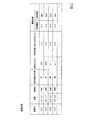
設備情報DB30は、電気設備を示す電気設備情報を記憶する。ここで、図2を参照して、電気設備情報について説明する。図2は、電気設備情報の一例を示す図である。図2に示したように、電気設備情報には、電気設備を識別する電気設備識別情報と、電気設備の位置を示す情報と、電気設備の名称を示す情報と、電気設備における架空地線の有無を示す情報と、架空地線を構成する素線の太さを示す情報と、架空地線に掛かる荷重(例えば、張力)を示す情報と、電気設備に関する履歴情報とが含まれる。なお、電気設備情報には、これらの情報に加えて、他の情報が含まれる構成であってもよく、これらの情報の一部又は全部に代えて他の情報が含まれる構成であってもよい。 The facility information DB 30 stores electrical facility information indicating electrical facilities. Here, electrical facility information will be described with reference to FIG. FIG. 2 is a diagram illustrating an example of electrical facility information. As shown in FIG. 2, the electrical equipment information includes electrical equipment identification information for identifying the electrical equipment, information indicating the location of the electrical equipment, information indicating the name of the electrical equipment, and the overhead ground wire in the electrical equipment. Information indicating presence / absence, information indicating the thickness of the strands constituting the imaginary ground wire, information indicating a load (for example, tension) applied to the imaginary ground wire, and history information regarding the electrical equipment are included. The electrical equipment information may be configured to include other information in addition to these information, or may be configured to include other information in place of some or all of these information. Good.
電気設備識別情報は、例えば、電気設備を識別する設備IDである。なお、電気設備識別情報は、設備IDに代えて、他の情報であってもよい。電気設備の位置を示す情報は、例えば、電気設備が設置された位置の緯度及び経度である。なお、電気設備の位置を示す情報は、緯度及び経度に代えて、他の情報であってもよい。電気設備の名称を示す情報は、図2において、設備名と称する。電気設備における架空地線の有無を示す情報には、図2において、架空地線が有る場合に「有」、架空地線が無い場合に「無」がそれぞれ格納される。なお、電気設備における架空地線の有無を示す情報は、「有」及び「無」に代えて、「0」と「1」等の他の情報であってもよい。 The electrical facility identification information is, for example, a facility ID that identifies the electrical facility. The electrical equipment identification information may be other information instead of the equipment ID. The information indicating the position of the electrical equipment is, for example, the latitude and longitude of the position where the electrical equipment is installed. The information indicating the position of the electrical equipment may be other information instead of the latitude and longitude. The information indicating the name of the electrical facility is referred to as the facility name in FIG. In the information indicating the presence / absence of an overhead ground wire in the electrical equipment, “present” is stored when there is an overhead ground wire, and “none” is stored when there is no overhead ground wire in FIG. The information indicating the presence / absence of the overhead ground wire in the electrical equipment may be other information such as “0” and “1” instead of “present” and “none”.
架空地線を構成する素線の太さを示す情報は、例えば、当該素線の直径である。なお、架空地線を構成する素線の太さを示す情報は、直径に代えて、断面積等の他の情報であってもよい。架空地線に掛かる荷重を示す情報は、当該荷重の大きさである。当該荷重は、種類が同じ架空地線同士であったとしても、電気設備が設置されている場所に応じて変化する。例えば、豪雪地帯に設置された電気設備の架空地線には、冬季において雪が付着するため、架空地線に掛かる荷重は大きくなる。なお、架空地線に掛かる荷重を示す情報には、季節等の属性を示す情報が対応付けられていてもよい。この場合、架空地線に掛かる荷重を示す情報は、季節毎の架空地線に掛かる荷重を示す。 The information indicating the thickness of the strands constituting the imaginary ground wire is, for example, the diameter of the strand. Note that the information indicating the thickness of the strands constituting the imaginary ground wire may be other information such as a cross-sectional area instead of the diameter. Information indicating the load applied to the overhead ground wire is the magnitude of the load. Even if the loads are the same type of overhead ground wire, the load varies depending on the location where the electrical equipment is installed. For example, since the snow is attached to the overhead ground wire of the electrical equipment installed in the heavy snow region, the load applied to the overhead ground wire becomes large. Note that information indicating an attribute such as season may be associated with the information indicating the load applied to the overhead ground wire. In this case, the information indicating the load applied to the overhead ground wire indicates the load applied to the overhead ground wire for each season.
電気設備に関する履歴情報には、補修履歴を示す情報と、点検履歴を示す情報とが含まれる。補修履歴を示す情報は、例えば、過去に補修が行われた回数である。なお、補修履歴を示す情報は、過去に補修が行われた年月日及び時刻等の他の情報であってもよい。また、点検履歴を示す情報は、例えば、電気設備の点検が行われた年月日及び時刻である。なお、点検履歴を示す情報は、これに代えて、電気設備の点検が行われた年月のみ等の他の情報であってもよい。
地図情報DB40は、全国の地図を示す地図情報を記憶する。
The history information related to the electrical equipment includes information indicating a repair history and information indicating an inspection history. The information indicating the repair history is, for example, the number of times repairs have been performed in the past. The information indicating the repair history may be other information such as the date and time when the repair was performed in the past. Further, the information indicating the inspection history is, for example, the date and time when the electrical equipment is inspected. Note that the information indicating the inspection history may be other information such as only the year and month when the electrical equipment is inspected.
Map information DB40 memorizes map information which shows a map of the whole country.
雷害判定装置50は、落雷によって発生する磁界の強度に基づいて、当該落雷の推定位置を含む範囲の電気設備の損害の程度を判定する。より具体的には、雷害判定装置50は、ネットワークNを介して落雷位置推定システム10から第1落雷位置情報を取得する。また、雷害判定装置50は、ネットワークNを介して磁界検出装置20から第2落雷位置情報を取得する。雷害判定装置50は、取得した第1落雷位置情報及び第2落雷位置情報のそれぞれが示す推定位置に基づいて、落雷した可能性の高い1以上の電気設備の電気設備情報を、ネットワークNを介して設備情報DB30から取得する。以下では、説明の便宜上、当該電気設備を、対象電気設備と称して説明する。なお、雷害判定装置50は、第1落雷位置情報と第2落雷位置情報とのうちいずれか一方が示す推定位置に基づいて、落雷した可能性の高い1以上の電気設備の電気設備情報を、ネットワークNを介して設備情報DB30から取得する構成であってもよい。
The lightning
また、雷害判定装置50は、ネットワークNを介して落雷位置推定システム10から電流波高値情報を取得する。また、雷害判定装置50は、ネットワークNを介して磁界検出装置20から磁界波形情報を取得する。雷害判定装置50は、取得した磁界波形情報に基づいて、発生した落雷の雷電流によって流れた電荷の量のうち少なくとも一部を表す量(落雷の電荷量)を算出する。この一例において、雷害判定装置50は、取得した磁界波形情報に基づいて、当該量として、発生した落雷の雷電流によって流れた電荷の総量の推定値である雷電荷量を算出する。雷害判定装置50は、算出した雷電荷量と、取得した電流波高値情報とに基づいて、落雷による対象電気設備の損害の程度を判定する雷害判定処理を行う。なお、雷害判定装置50は、磁界波形情報に代えて、落雷によって発生する電磁波の磁界強度のピーク値に基づいて当該雷電荷量を算出する構成等、磁界成分に基づく他の方法によって当該雷電荷量を算出する構成であってもよい。雷害判定装置50が当該ピーク値に基づいて当該雷電荷量を算出する場合、雷害判定装置50は、磁界検出装置20から、磁界強度のピーク値を示す情報を取得する。
Further, the lightning
雷害判定装置50は、雷害判定処理の結果、対象電気設備の損害が大きいと判定した場合、雷害判定処理の結果を示す情報と、対象電気設備の点検を促す情報とを表示する。一方、雷害判定装置50は、雷害判定処理の結果、対象電気設備の損害が小さいと判定した場合、雷害判定処理の結果を示す情報を表示する。
When it is determined that the damage of the target electrical equipment is large as a result of the lightning damage determination process, the lightning
雷害判定処理の結果を示す情報を表示する際、雷害判定装置50は、例えば、対象電気設備の位置を含む地域の地図情報を、ネットワークNを介して地図情報DB40から取得する。そして、雷害判定装置50は、取得した地図情報に基づいて、対象電気設備の位置を示す情報が重畳された地図を、雷害判定処理の結果を示す情報とともに表示する。これらにより、雷害判定装置50は、電気設備の点検の効率を向上させることができる。なお、雷害判定装置50は、対象電気設備の位置を示す情報が重畳された地図を表示させず、雷害判定処理の結果を示す情報のみを表示する構成であってもよく、雷害判定処理の結果を示す情報とともに地図以外の他の情報を表示する構成であってもよい。
When displaying information indicating the result of the lightning damage determination process, the lightning
また、雷害判定装置50は、ネットワークNを介した情報処理端末60からの要求に応じて、雷害判定処理の結果を示す情報を、対象電気設備の位置を示す情報が重畳された地図を示す情報とともに、ネットワークNを介して情報処理端末60に送信する。なお、雷害判定装置50は、ネットワークNを介した情報処理端末60からの要求に応じて、雷害判定処理の結果を示す情報のみを、ネットワークNを介して情報処理端末60に送信する構成であってもよく、雷害判定処理の結果を示す情報とともに地図以外の他の情報をネットワークNを介して情報処理端末60に送信する構成であってもよい。
Further, in response to a request from the
情報処理端末60は、例えば、多機能携帯電話端末(スマートフォン)や携帯電話端末、タブレットPC(Personal Computer)、通信機能を有する電子書籍リーダー、PDA(Personal Digital Assistant)、ノートPC等のモバイル端末である。なお、ユーザー端末は、デスクトップPC等の情報処理端末(又は情報処理装置)であってもよい。情報処理端末60は、ユーザーから受け付けた操作に基づいて、雷害判定処理の結果を示す情報と、対象電気設備の位置を示す情報が重畳された地図を示す情報との取得の要求を、ネットワークNを介して雷害判定装置50に送信する。情報処理端末60は、当該要求の応答として、雷害判定処理の結果を示す情報と、対象電気設備の位置を示す情報が重畳された地図を示す情報とを、ネットワークNを介して雷害判定装置50から取得する。
The
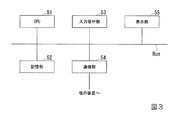
次に、図3を参照し、雷害判定装置50のハードウェア構成について説明する。図3は、雷害判定装置50のハードウェア構成の一例を示す図である。雷害判定装置50は、例えば、CPU(Central Processing Unit)51と、記憶部52と、入力受付部53と、通信部54と、表示部55を備える。また、雷害判定装置50は、通信部54を介して他の装置と通信を行う。これらの構成要素は、バスBusを介して相互に通信可能に接続されている。
Next, the hardware configuration of the lightning
CPU51は、記憶部52に格納された各種プログラムを実行する。
記憶部52は、例えば、HDD(Hard Disk Drive)やSSD(Solid State Drive)、EEPROM(Electrically Erasable Programmable Read−Only Memory)、ROM(Read−Only Memory)、RAM(Random Access Memory)などを含む。記憶部52は、雷害判定装置50が処理する各種情報や画像、プログラム、前述の雷害判定処理に用いられる判定条件を示す判定条件情報等を格納する。なお、記憶部52は、雷害判定装置50に内蔵されるものに代えて、USB等のデジタル入出力ポート等によって接続された外付け型の記憶装置でもよい。
The
The
入力受付部53は、例えば、キーボードやマウス、タッチパッド等を備えたティーチングペンダントや、その他の入力装置である。なお、入力受付部53は、タッチパネルとして表示部55と一体に構成されてもよい。
通信部54は、例えば、USB等のデジタル入出力ポートやイーサネット(登録商標)ポート等を含んで構成される。
表示部55は、例えば、液晶ディスプレイパネル、あるいは、有機EL(ElectroLuminescence)ディスプレイパネルである。
The
The
The
次に、図4を参照して、雷害判定装置50の機能構成について説明する。図4は、雷害判定装置50の機能構成の一例を示す図である。雷害判定装置50は、記憶部52と、入力受付部53と、通信部54と、表示部55と、制御部56を備える。
Next, the functional configuration of the lightning
制御部56は、雷害判定装置50の全体を制御する。制御部56は、取得部71と、電荷算出部73と、落雷判定部74と、雷害判定部75と、表示制御部77と、送信制御部79を備える。制御部56が備えるこれらの機能部は、例えば、CPU51が、記憶部52に記憶された各種プログラムを実行することで実現される。また、これらの機能部のうちの一部又は全部は、LSI(Large Scale Integration)やASIC(Application Specific Integrated Circuit)等のハードウェア機能部であってもよい。
The
取得部71は、落雷位置情報取得部711と、電流波高値情報取得部713と、磁界波形情報取得部715と、設備情報取得部717と、判定条件情報取得部719と、地図情報取得部721を備える。
The
落雷位置情報取得部711は、ネットワークNを介して第1落雷位置情報を落雷位置推定システム10から取得する。また、落雷位置情報取得部711は、ネットワークNを介して第2落雷位置情報を磁界検出装置20から取得する。
電流波高値情報取得部713は、ネットワークNを介して電流波高値情報を落雷位置推定システム10から取得する。
磁界波形情報取得部715は、ネットワークNを介して磁界波形情報を磁界検出装置20から取得する。
The lightning strike position
The current peak value information acquisition unit 713 acquires the current peak value information from the lightning strike
The magnetic field waveform
設備情報取得部717は、ネットワークNを介して電気設備情報を設備情報DB30から取得する。
判定条件情報取得部719は、記憶部52から判定条件情報を取得する。
地図情報取得部721は、ネットワークNを介して地図情報を地図情報DB40から取得する。
The facility
The determination condition
The map
電荷算出部73は、磁界波形情報取得部715が取得した磁界波形情報に基づいて、前述の雷電荷量を算出する。
落雷判定部74は、落雷位置情報取得部711が取得した第1落雷位置情報及び第2落雷位置情報に基づいて、第1落雷位置情報に含まれる推定位置の誤差範囲と、第2落雷位置情報に含まれる推定位置の誤差範囲とが重なる部分があるか否かを判定することにより、2つの推定位置が一致するか否かを判定する。
雷害判定部75は、電荷算出部73が算出した雷電荷量と、電流波高値情報取得部713が取得した電流波高値情報と、判定条件情報取得部719が取得した判定条件情報とに基づいて、落雷による対象電気設備の損害の程度を判定する雷害判定処理を行う。
The
The lightning
The lightning
表示制御部77は、雷害判定部75が雷害判定処理を行った結果として対象電気設備の損害の程度が大きいと判定された場合、雷害判定処理の結果を示す情報と、対象電気設備の点検を促す情報とを表示する画像を生成する。一方、雷害判定装置50は、雷害判定部75が雷害判定処理を行った結果として対象電気設備の損害の程度が小さいと判定された場合、雷害判定処理の結果を示す情報を表示する画像を生成する。
When it is determined that the degree of damage of the target electrical facility is large as a result of the lightning
また、表示制御部77は、雷害判定処理の結果を示す情報を表示する画像を生成する際、地図情報取得部721が取得した地図情報に基づいて、対象電気設備の位置を示す情報が重畳された地図を、雷害判定処理の結果を示す情報とともに表示する画像を生成する。表示制御部77は、生成した画像を表示部55に表示させる。
Moreover, when the
また、送信制御部79は、ネットワークNを介した情報処理端末60からの要求に応じて、雷害判定処理の結果を示す情報を、対象電気設備の位置を示す情報が重畳された地図を示す情報とともに、ネットワークNを介して情報処理端末60に送信する。
Further, in response to a request from the
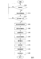
次に、図5を参照して、雷害判定装置50が備える制御部56による雷害判定処理について説明する。図5は、雷害判定装置50が備える制御部56による雷害判定処理の流れの一例を示すフローチャートである。
Next, with reference to FIG. 5, the lightning damage determination process by the
制御部56は、落雷が発生するまで待機する(ステップS100)。ここで、ステップS100の処理について説明する。例えば、雷害判定装置50が備える制御部56は、落雷が発生した際、落雷位置推定システム10から落雷が発生したことを示す情報を取得する。このように、制御部56は、落雷が発生した際、他の装置から落雷が発生したことを示す情報を取得することにより、ステップS100において落雷が発生したと判定する。
The
ステップS100において落雷が発生したと制御部56が判定した場合(ステップS100−Yes)、落雷位置情報取得部711は、ネットワークNを介して落雷位置推定システム10から第1落雷位置情報を取得する。また、落雷位置推定システム10は更に、ネットワークNを介して磁界検出装置20から第2落雷位置情報を取得する(ステップS110)。
When the
次に、落雷判定部74は、ステップS110において落雷位置情報取得部711が取得した第1落雷位置情報及び第2落雷位置情報に基づいて、第1落雷位置情報が示す推定位置の誤差範囲と、第2落雷位置情報が示す推定位置の誤差範囲とに重なる部分があるか否かを判定する(ステップS115)。すなわち、落雷判定部74は、これら2つの推定位置が所定の誤差範囲内において一致するか否かを判定する。所定の誤差範囲は、例えば、1標準偏差によって表される範囲であるが、これに代えて、他の範囲であってもよい。
Next, the lightning
2つの推定位置が所定の誤差範囲内において一致しないと落雷判定部74が判定した場合(ステップS115−No)、制御部56は、落雷が発生していないにも拘わらず、何らかのノイズにより落雷が発生したと検出された可能性が高いため、ステップS100に遷移し、再び落雷が発生するまで待機する。一方、2つの推定位置が一致すると落雷判定部74が判定した場合(ステップS115−Yes)、電流波高値情報取得部713は、ネットワークNを介して落雷位置推定システム10から電流波高値情報を取得する(ステップS120)。
When the lightning
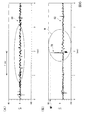
次に、磁界波形情報取得部715は、磁界波形情報を、ネットワークNを介して磁界検出装置20から取得する(ステップS130)。ここで、磁界波形情報取得部715が取得する磁界波形情報について説明する。雷放電により発生する電磁波の成分のうち極超長波(ELF(Extremely Low Frequency)波)は、大地と電離層の間を空洞共振器とするシューマン共振を起こす。このシューマン共振を起こすELF波は、地球全体で1秒間に平均50回程度の頻度で発生する複数の雷放電によって常に励起されている。また、このようなシューマン共振の波形は、共振現象のため準周期的な連続波形を成している。ところが、スーパーボルトと呼ばれる大きな雷電荷量を伴う大規模な雷放電が生じた場合、シューマン共振の周波数帯では、磁界成分の強度の時間的変化を示す波形からは、図6に示すように鋭く立ち上がり、その後、減衰振動へと遷移する過渡波形が観測される。このような波形の変化は、ELFトランジェントと呼ばれる。
Next, the magnetic field waveform
図6は、シューマン共振のうちの磁界成分の強度の時間的変化を示す波形の一例と、ELFトランジェントが生じた際の当該波形の一例を示す図である。図6(A)は、シューマン共振のうちの磁界成分の強度の時間的変化を示す波形の一例である。以下では、説明の便宜上、シューマン共振のうちの磁界成分の強度の時間的変化を示す波形を、シューマン共振の波形と称して説明する。図6(A)に示したように、シューマン共振の波形G1は、準周期的な連続波形を成している。波形G1は、雷電流によって流れる電荷の量が大きな雷放電が、磁界検出装置20の近くにおいて生じていない時間帯のシューマン共振の波形である。磁界検出装置20の近くとは、磁界検出装置20を中心とした所定の半径の円形領域の範囲内のことである。所定の半径は、数キロメートル程度である。
FIG. 6 is a diagram illustrating an example of a waveform showing temporal changes in the intensity of the magnetic field component in the Schumann resonance and an example of the waveform when an ELF transient occurs. FIG. 6A is an example of a waveform showing a temporal change in the intensity of the magnetic field component in the Schumann resonance. In the following, for convenience of explanation, the waveform showing the temporal change in the intensity of the magnetic field component in the Schumann resonance will be referred to as the Schumann resonance waveform. As shown in FIG. 6A, the Schumann resonance waveform G1 is a quasi-periodic continuous waveform. The waveform G <b> 1 is a Schumann resonance waveform in a time zone in which a lightning discharge with a large amount of charge caused by the lightning current is not generated near the magnetic
一方、図6(B)は、ELFトランジェントが生じた際のシューマン共振の波形の一例である。図6(B)に示したシューマン共振の波形G2には、実線Wによって囲まれた範囲内において、ELFトランジェントTRが生じている。このELFトランジェントTRが生じた時刻の直前に、雷電荷量の大きな雷放電が起きたと考えられる。磁界検出装置20は、このELFトランジェントTRが生じている波形、すなわちELFトランジェントTRを引き起こした雷放電によって発生したELF波の磁界成分の強度の時間的変化を示す磁界波形情報を算出する。そして、磁界検出装置20は、算出した磁界波形情報を、雷害判定装置50に送信する。すなわち、磁界波形情報取得部715は、図6(B)に示した波形、すなわちELFトランジェントTRが生じている時間帯を含む磁界成分の強度の時間的変化を示す磁界波形情報を取得する。なお、図6において、ELFトランジェントTRが生じている時間帯とは、すなわち波形G2におけるピーク値MPを含む時間帯のことである。
On the other hand, FIG. 6B is an example of a Schumann resonance waveform when an ELF transient occurs. In the Schumann resonance waveform G2 shown in FIG. 6B, an ELF transient TR occurs in the range surrounded by the solid line W. It is thought that a lightning discharge with a large lightning charge amount occurred just before the time when this ELF transient TR occurred. The magnetic
次に、設備情報取得部717は、例えば、ステップS110において落雷位置情報取得部711が取得した第1落雷位置情報及び第2落雷位置情報に基づいて、1以上の対象電気設備の電気設備情報を、ネットワークNを介して設備情報DB30から取得する(ステップS140)。
Next, the facility
ここで、ステップS140の処理について説明する。設備情報取得部717は、例えば、第1落雷位置情報が示す落雷の推定位置と、第2落雷位置情報が示す落雷の推定位置とを結ぶ直線の中点の位置を落雷の位置として算出する。そして、設備情報取得部717は、設備情報DB30に記憶された電気設備情報のうち、算出した落雷の位置を中心とした所定の範囲内に設置されている電気設備の電気設備情報を、対象電気設備の電気設備情報として取得する。なお、設備情報取得部717は、落雷の位置を、他の方法によって算出する構成であってもよい。
Here, the process of step S140 will be described. The facility
次に、判定条件情報取得部719は、記憶部52に予め記憶された判定条件を記憶部52から取得する(ステップS150)。この判定条件は、前述したように雷害判定処理に用いられる。次に、電荷算出部73は、ステップS130において磁界波形情報取得部715が取得した磁界波形情報に基づいて雷電荷量を算出する(ステップS160)。
Next, the determination condition
ここで、ステップS160の処理について説明する。電荷算出部73は、磁界波形情報取得部715が取得した磁界波形情報に基づいて、磁界波形情報が示す波形をフーリエ変換することにより、磁界成分の強度の振幅スペクトルを算出する。そして、電荷算出部73は、算出した振幅スペクトルに基づいて、以下に示した式(1)により、落雷の雷電流によって生じる電流モーメントを算出する。
Here, the process of step S160 will be described. The

ここで、Iは、雷電流であり、fは、ELF帯の周波数である。Hは、周波数fにおける水平磁界の振幅スペクトルである。aは、地球の半径であり、hは、電離層高度である。vは、伝播定数であり、Pは、ルジャンドル陪関数である。Pに付随する上付き添え字である1と、下付き添え字であるvとはそれぞれ、ルジャンドル陪関数のパラメーターである。そして、θは、空電源位置から磁界検出装置20が備える受信装置までの角距離である。上記の式(1)によって算出される雷電流モーメントにおいて、雷電流の時間的変化を表す波形が指数間的に減少し、且つ当該波形の減少する時間が非常に短いと仮定した場合、当該雷電流モーメントは、以下に示した式(2)のように雷電荷モーメントに近似することができる。
Here, I is the lightning current, and f is the ELF band frequency. H is the amplitude spectrum of the horizontal magnetic field at frequency f. a is the radius of the earth and h is the ionospheric altitude. v is a propagation constant and P is a Legendre power function. The superscript 1 associated with P and the subscript v, which are subscripts, are parameters of the Legendre function, respectively. Θ is an angular distance from the empty power supply position to the receiving device included in the magnetic
ここで、Qは雷電荷量であり、dsは、落雷の雷道の長さ(距離)である。すなわち、電荷算出部73は、上記の式(1)によって算出した振幅スペクトルHを用いて雷電流モーメントを算出し、上記の近似を用いて式(2)から雷電荷量を算出する。
Here, Q is the amount of lightning charge, and ds is the length (distance) of the lightning strike. That is, the
ステップS160において電荷算出部73が雷電荷量を算出した後、雷害判定部75は、ステップS160において算出された雷電荷量と、ステップS120において取得した電流波高値情報と、ステップS150において判定条件情報取得部719が取得した判定条件情報とに基づいて、落雷による対象電気設備の損害の程度を判定する雷害判定処理を行う(ステップS170)。
After the
ここで、判定条件情報と雷害判定処理について説明する。本実施形態における判定条件情報が示す判定条件は、以下に示す条件1)及び条件2)のいずれか一方を満たすことである。 Here, determination condition information and lightning damage determination processing will be described. The determination condition indicated by the determination condition information in the present embodiment is to satisfy one of the following conditions 1) and 2).
1)雷電荷量≧100[C]
2)電流波高値≧100[kA]
1) Lightning charge ≥ 100 [C]
2) Current peak value ≧ 100 [kA]
上記の条件1)及び条件2)に示した100[C]や100[kA]という閾値は、あくまでも一例である。これらの閾値は、電気設備を用いた実験によって決められる。例えば、電気設備の架空地線に対して直流アーク試験を行うことにより、上記の条件1)の雷電荷量に対する閾値が決められる。 The threshold values of 100 [C] and 100 [kA] shown in the above conditions 1) and 2) are merely examples. These threshold values are determined by experiments using electrical equipment. For example, a threshold value for the lightning charge amount of the above condition 1) is determined by performing a DC arc test on an overhead ground wire of an electrical facility.
雷害判定部75は、ステップS160において算出された雷電荷量と、ステップS120において取得した電流波高値情報とに基づいて、上記の条件1)又は条件2)が満たされているか否かを判定する。雷害判定部75は、上記の条件1)と条件2)のうちいずれか一方又は両方が満たされていると判定した場合、対象電気設備の損害の程度が大きいと判定する。一方、雷害判定部75は、上記の条件1)と条件2)のいずれも満たされていないと判定した場合、対象電気設備の損害の程度が小さいと判定する。
The lightning
次に、地図情報取得部721は、ステップS140において取得した電気設備情報に基づいて、対象電気設備が設置されている位置を含む地域の地図を示す地図情報を取得する(ステップS175)。
Next, the map
次に、表示制御部77は、ステップS170において判定された結果を表示部55に表示する画像を生成する。そして、表示制御部77は、生成した画像を表示部55に表示させる(ステップS180)。ここで、ステップS180の処理について説明する。表示制御部77は、ステップS170における雷害判定処理の結果、対象電気設備の損害の程度が大きいと雷害判定部75が判定した場合、雷害判定処理の結果を示す情報と、対象電気設備の点検を促す情報とを表示する画像を生成する。一方、表示制御部77は、ステップS170における雷害判定処理の結果、対象電気設備の損害の程度が小さいと雷害判定部75が判定した場合、雷害判定処理の結果を示す情報を表示する画像を生成する。
Next, the
また、表示制御部77は、雷害判定処理の結果を示す情報を表示する画像を生成する際、ステップS175において地図情報取得部721が取得した地図情報に基づいて、対象電気設備の位置を示す情報が重畳された地図を、雷害判定処理の結果を示す情報とともに表示する画像を生成する。
In addition, when generating an image that displays information indicating the result of the lightning damage determination process, the
次に、図7を参照して、雷害判定装置50が備える制御部56が雷害判定処理の結果を示す情報を、対象電気設備の位置を示す情報が重畳された地図を示す情報とともに情報処理端末60に送信する処理について説明する。図7は、雷害判定装置50が備える制御部56が雷害判定処理の結果を示す情報を、対象電気設備の位置を示す情報が重畳された地図を示す情報とともに情報処理端末60に送信する処理の流れの一例を示すフローチャートである。なお、図7に示したフローチャートは、すでに図5に示したフローチャートの処理が実行され、雷害判定処理が行われた後に実行される処理である場合について説明する。
Next, referring to FIG. 7, information indicating the result of the lightning damage determination process performed by the
送信制御部79は、ネットワークNを介して情報処理端末60から雷害判定処理の結果を示す情報取得の要求を取得するまで待機する(ステップS200)。情報処理端末60から雷害判定処理の結果を示す情報取得の要求を取得した場合(ステップS200−Yes)、送信制御部79は、雷害判定処理の結果を示す情報を、対象電気設備の位置を示す情報が重畳された地図を示す情報とともに、ネットワークNを介して情報処理端末60に送信する(ステップS210)。
The
<実施形態の変形例1>
以下、本発明の実施形態の変形例1について説明する。本実施形態の変形例1に係る雷害判定システム1では、雷害判定処理に用いられる判定条件が、上記の実施形態と異なる。
<
Hereinafter,
本実施形態の変形例1における判定条件は、以下に示す条件1A)及び条件2A)を満たし、且つ条件3A)又は条件4A)のいずれかを満たすことである。 The determination condition in the first modification of the present embodiment is that the following condition 1A) and condition 2A) are satisfied, and either condition 3A) or condition 4A) is satisfied.
1A)架空地線を有している
2A)架空地線の太さが所定の太さ未満である
3A)雷電荷量≧100[C]
4A)電流波高値≧100[kA]
1A) Having an overhead ground wire 2A) The thickness of the overhead ground wire is less than a predetermined thickness 3A) Amount of lightning charge ≧ 100 [C]
4A) Current peak value ≧ 100 [kA]
すなわち、本実施形態の変形例1に係る雷害判定部75は、図5に示したステップS170において、ステップS160において算出された雷電荷量と、ステップS120において取得した電流波高値情報と、ステップS150において判定条件情報取得部719が取得した判定条件情報と、ステップS140において取得した対象電気設備の電気設備情報とに基づいて、落雷による対象電気設備の損害の程度を判定する雷害判定処理を行う。
That is, the lightning
雷害判定部75は、ステップS140において取得した対象電気設備の電気設備情報を参照し、上記の条件1A)及び条件2A)を満たす対象電気設備が存在するか否かを判定する。当該対象電気設備が存在しない場合、雷害判定部75は、上記の条件1A)及び条件2A)が満たされていないと判定し、対象電気設備の損害の程度が小さいと判定する。一方、当該対象電気設備が存在する場合、雷害判定部75は、ステップS160において算出された雷電荷量と、ステップS120において取得した電流波高値情報とに基づいて、上記の条件3A)又は条件4A)が満たされているか否かを判定する。雷害判定部75は、上記の条件3A)と条件4A)のうちいずれか一方又は両方が満たされていると判定した場合、対象電気設備の損害の程度が大きいと判定する。
The lightning
このように、本実施形態の変形例1に係る雷害判定装置50は、上記の条件1A)及び条件2A)を満たし、且つ条件3A)又は条件4A)のいずれかを満たすか否かによって、対象電気設備の損害の程度を判定する。これにより、雷害判定装置50は、対象電気設備が有する架空地線等の部材に応じて、対象電気設備の損害の程度を判定することができ、その結果、電気設備の点検の効率を向上させることができる。
As described above, the lightning
<実施形態の変形例2>
以下、本発明の実施形態の変形例2について説明する。本実施形態の変形例2に係る雷害判定システム1では、雷害判定処理に用いられる判定条件が、上記の実施形態及び実施形態の変形例1と異なる。
<
Hereinafter,
本実施形態の変形例2における判定条件は、以下に示す条件1B)及び条件2B)を満たし、且つ条件3B)又は条件4B)のいずれかを満たすことである。 The determination condition in the second modification of the present embodiment is that the following condition 1B) and condition 2B) are satisfied, and either condition 3B) or condition 4B) is satisfied.
1B)架空地線を有している
2B)架空地線に掛かる荷重が所定荷重以上
3B)雷電荷量≧100[C]
4B)電流波高値≧100[kA]
1B) Having an overhead ground wire 2B) The load applied to the overhead ground wire is greater than or equal to a predetermined load 3B) Lightning charge amount ≧ 100 [C]
4B) Current peak value ≧ 100 [kA]
ここで、所定荷重は、例えば、40[kN]である。なお、この40[kN]という値は、一例に過ぎず、所定荷重は、他の値であってもよい。また、所定荷重は、豪雪地帯のように夏季と冬季によって異なる場合があるため、季節毎に異なる値であってもよい。
本実施形態の変形例2に係る雷害判定部75は、本実施形態の変形例1に係る雷害判定部75と同様に、図5に示したステップS170において、ステップS160において算出された雷電荷量と、ステップS120において取得した電流波高値情報と、ステップS150において判定条件情報取得部719が取得した判定条件情報と、ステップS140において取得した対象電気設備の電気設備情報とに基づいて、落雷による対象電気設備の損害の程度を判定する雷害判定処理を行う。
Here, the predetermined load is, for example, 40 [kN]. The value of 40 [kN] is only an example, and the predetermined load may be another value. Moreover, since the predetermined load may vary depending on the summer and winter seasons as in a heavy snowy region, the predetermined load may be different for each season.
Similarly to the lightning
雷害判定部75は、ステップS140において取得した対象電気設備の電気設備情報を参照し、上記の条件1B)及び条件2B)を満たす対象電気設備が存在するか否かを判定する。当該対象電気設備が存在しない場合、雷害判定部75は、上記の条件1B)及び条件2B)が満たされていないと判定し、対象電気設備の損害の程度が小さいと判定する。一方、当該対象電気設備が存在する場合、雷害判定部75は、ステップS160において算出された雷電荷量と、ステップS120において取得した電流波高値情報とに基づいて、上記の条件3B)又は条件4B)が満たされているか否かを判定する。雷害判定部75は、上記の条件3B)と条件3B)のうちいずれか一方又は両方が満たされていると判定した場合、対象電気設備の損害の程度が大きいと判定する。
The lightning
このように、本実施形態の変形例2に係る雷害判定装置50は、上記の条件1B)及び条件2B)を満たし、且つ条件3B)又は条件4B)のいずれかを満たすか否かによって、対象電気設備の損害の程度を判定する。これにより、雷害判定装置50は、対象電気設備が有する架空地線も掛かる荷重等の環境要因(外的要因)に応じて、対象電気設備の損害の程度を判定することができ、その結果、電気設備の点検の効率を向上させることができる。
As described above, the lightning
<実施形態の変形例3>
以下、本発明の実施形態の変形例3について説明する。本実施形態の変形例3に係る雷害判定システム1では、雷害判定処理に用いられる判定条件が、上記の実施形態、実施形態の変形例1、実施形態の変形例2と異なる。
<Modification 3 of embodiment>
Hereinafter, Modification 3 of the embodiment of the present invention will be described. In the lightning
本実施形態の変形例3における判定条件は、以下に示す条件1C)及び条件2C)を満たし、且つ条件3C)又は条件4C)のいずれかを満たすことである。 The determination condition in the third modification of the present embodiment is that the following conditions 1C) and 2C) are satisfied, and either condition 3C) or condition 4C) is satisfied.
1C)架空地線を有している
2C)過去に補修されている
3C)雷電荷量≧100[C]
4C)電流波高値≧100[kA]
1C) Has an overhead ground wire 2C) Repaired in the past 3C) Lightning charge amount ≧ 100 [C]
4C) Current peak value ≧ 100 [kA]
本実施形態の変形例3に係る雷害判定部75は、本実施形態の変形例1に係る雷害判定部75と同様に、図5に示したステップS170において、ステップS160において算出された雷電荷量と、ステップS120において取得した電流波高値情報と、ステップS150において判定条件情報取得部719が取得した判定条件情報と、ステップS140において取得した対象電気設備の電気設備情報とに基づいて、落雷による対象電気設備の損害の程度を判定する雷害判定処理を行う。
Similarly to the lightning
雷害判定部75は、ステップS140において取得した対象電気設備の電気設備情報を参照し、上記の条件1C)及び条件2C)を満たす対象電気設備が存在するか否かを判定する。当該対象電気設備が存在しない場合、雷害判定部75は、上記の条件1C)及び条件2C)が満たされていないと判定し、対象電気設備の損害の程度が小さいと判定する。一方、当該対象電気設備が存在する場合、雷害判定部75は、ステップS160において算出された雷電荷量と、ステップS120において取得した電流波高値情報とに基づいて、上記の条件3C)又は条件4C)が満たされているか否かを判定する。雷害判定部75は、上記の条件3C)と条件3C)のうちいずれか一方又は両方が満たされていると判定した場合、対象電気設備の損害の程度が大きいと判定する。
The lightning
このように、本実施形態の変形例3に係る雷害判定装置50は、上記の条件1C)及び条件2C)を満たし、且つ条件3C)又は条件4C)のいずれかを満たすか否かによって、対象電気設備の損害の程度を判定する。これにより、雷害判定装置50は、対象電気設備が過去に補修されているか否かに応じて、対象電気設備の損害の程度を判定することができ、その結果、電気設備の点検の効率を向上させることができる。対象電気設備が補修されている場合、補修されていない場合に比べて、電気設備における補修箇所の強度が落ちている可能性が高い。このため、対象電気設備が過去に補修されているか否かに応じて対象電気設備の損害の程度を判定することは、電気設備の点検を効率化するために重要である。
As described above, the lightning
<実施形態の変形例4>
以下、本発明の実施形態の変形例4について説明する。本実施形態の変形例4に係る雷害判定システム1では、雷害判定処理に用いられる判定条件が、上記の実施形態、実施形態の変形例1〜実施形態の変形例3と異なる。
<Modification 4 of embodiment>
Hereinafter, Modification 4 of the embodiment of the present invention will be described. In the lightning
本実施形態の変形例3における判定条件は、以下に示す条件1D)及び条件2D)を満たし、且つ条件3D)又は条件4D)のいずれかを満たすことである。 The determination condition in the third modification of the present embodiment is that the following condition 1D) and condition 2D) are satisfied, and either condition 3D) or condition 4D) is satisfied.
1D)架空地線を有している
2D)前回の点検から所定期間以上経過している
3D)雷電荷量≧100[C]
4D)電流波高値≧100[kA]
1D) Has an overhead ground wire 2D) Has passed a predetermined period since the previous inspection 3D) Lightning charge amount ≧ 100 [C]
4D) Current peak value ≧ 100 [kA]
本実施形態の変形例4に係る雷害判定部75は、本実施形態の変形例1に係る雷害判定部75と同様に、図5に示したステップS170において、ステップS160において算出された雷電荷量と、ステップS120において取得した電流波高値情報と、ステップS150において判定条件情報取得部719が取得した判定条件情報と、ステップS140において取得した対象電気設備の電気設備情報とに基づいて、落雷による対象電気設備の損害の程度を判定する雷害判定処理を行う。
Similarly to the lightning
雷害判定部75は、ステップS140において取得した対象電気設備の電気設備情報を参照し、上記の条件1D)及び条件2D)を満たす対象電気設備が存在するか否かを判定する。当該対象電気設備が存在しない場合、雷害判定部75は、上記の条件1D)及び条件2D)が満たされていないと判定し、対象電気設備の損害の程度が小さいと判定する。一方、当該対象電気設備が存在する場合、雷害判定部75は、ステップS160において算出された雷電荷量と、ステップS120において取得した電流波高値情報とに基づいて、上記の条件3D)又は条件4D)が満たされているか否かを判定する。雷害判定部75は、上記の条件3D)と条件3D)のうちいずれか一方又は両方が満たされていると判定した場合、対象電気設備の損害の程度が大きいと判定する。
The lightning
このように、本実施形態の変形例4に係る雷害判定装置50は、上記の条件1D)及び条件2D)を満たし、且つ条件3D)又は条件4D)のいずれかを満たすか否かによって、対象電気設備の損害の程度を判定する。これにより、雷害判定装置50は、対象電気設備が前回の点検から所定期間以上経過しているか否かに応じて、対象電気設備の損害の程度を判定することができ、その結果、電気設備の点検の効率を向上させることができる。前回の点検から所定期間以上経過している場合、経年変化や過去の落雷等の外的要因によって電気設備に損傷が発生している可能性が高い。このため、前回の点検から所定期間以上経過しているか否かに応じて対象電気設備の損害の程度を判定することは、電気設備の点検を効率化するために重要である。
As described above, the lightning
以上説明したように、本実施形態における雷害判定システム1は、落雷によって発生する磁界の強度に基づいて、当該落雷の推定位置を含む範囲の電気設備の損害の程度を判定する。これにより、雷害判定システム1は、電気設備の点検の効率を向上させることができる。
As described above, the lightning
以上、この発明の実施形態を、図面を参照して詳述してきたが、具体的な構成はこの実施形態に限られるものではなく、この発明の要旨を逸脱しない限り、変更、置換、削除等されてもよい。 The embodiment of the present invention has been described in detail with reference to the drawings. However, the specific configuration is not limited to this embodiment, and changes, substitutions, deletions, and the like are possible without departing from the gist of the present invention. May be.
また、以上に説明した装置(例えば、雷害判定装置50)における任意の構成部の機能を実現するためのプログラムを、コンピューター読み取り可能な記録媒体に記録し、そのプログラムをコンピューターシステムに読み込ませて実行するようにしてもよい。なお、ここでいう「コンピューターシステム」とは、OS(Operating System)や周辺機器等のハードウェアを含むものとする。また、「コンピューター読み取り可能な記録媒体」とは、フレキシブルディスク、光磁気ディスク、ROM、CD(Compact Disk)−ROM等の可搬媒体、コンピューターシステムに内蔵されるハードディスク等の記憶装置のことをいう。さらに「コンピューター読み取り可能な記録媒体」とは、インターネット等のネットワークや電話回線等の通信回線を介してプログラムが送信された場合のサーバーやクライアントとなるコンピューターシステム内部の揮発性メモリー(RAM)のように、一定時間プログラムを保持しているものも含むものとする。 In addition, a program for realizing the function of an arbitrary component in the device described above (for example, the lightning damage determination device 50) is recorded on a computer-readable recording medium, and the program is read into a computer system. You may make it perform. Here, the “computer system” includes hardware such as an OS (Operating System) and peripheral devices. The “computer-readable recording medium” refers to a portable medium such as a flexible disk, a magneto-optical disk, a ROM, a CD (Compact Disk) -ROM, or a storage device such as a hard disk built in the computer system. . Furthermore, “computer-readable recording medium” means a volatile memory (RAM) inside a computer system that becomes a server or client when a program is transmitted via a network such as the Internet or a communication line such as a telephone line. In addition, those holding programs for a certain period of time are also included.
また、上記のプログラムは、このプログラムを記憶装置等に格納したコンピューターシステムから、伝送媒体を介して、あるいは、伝送媒体中の伝送波により他のコンピューターシステムに伝送されてもよい。ここで、プログラムを伝送する「伝送媒体」は、インターネット等のネットワーク(通信網)や電話回線等の通信回線(通信線)のように情報を伝送する機能を有する媒体のことをいう。
また、上記のプログラムは、前述した機能の一部を実現するためのものであってもよい。さらに、上記のプログラムは、前述した機能をコンピューターシステムにすでに記録されているプログラムとの組み合わせで実現できるもの、いわゆる差分ファイル(差分プログラム)であってもよい。
In addition, the above program may be transmitted from a computer system storing the program in a storage device or the like to another computer system via a transmission medium or by a transmission wave in the transmission medium. Here, the “transmission medium” for transmitting the program refers to a medium having a function of transmitting information, such as a network (communication network) such as the Internet or a communication line (communication line) such as a telephone line.
Further, the above program may be for realizing a part of the functions described above. Further, the program may be a so-called difference file (difference program) that can realize the above-described functions in combination with a program already recorded in the computer system.
1 雷害判定システム、10 落雷位置推定システム、20 磁界検出装置、30 設備情報DB、40 地図情報DB、50 雷害判定装置、51 CPU、52 記憶部、53 入力受付部、54 通信部、55 表示部、56 制御部、60 情報処理端末、71 取得部、73 電荷算出部、74 落雷判定部、75 雷害判定部、77 表示制御部、79 送信制御部、711 落雷位置情報取得部、713 電流波高値情報取得部、715 磁界波形情報取得部、717 設備情報取得部、719 判定条件情報取得部、721 地図情報取得部
DESCRIPTION OF
Claims (6)
前記電気設備情報には、前記範囲の前記電気設備のそれぞれが架空地線を有するか否かを示す架空地線有無情報が含まれており、
前記強度と、前記電気設備情報に含まれる前記架空地線有無情報とに基づいて、前記損害の程度を判定する、
雷害判定装置。 And intensity of the magnetic field generated by the lightning strike, based on the electrical equipment information indicating the electrical equipment range including the estimated location of the lightning, determines the extent of damage in the range of electrical equipment, including an estimated position of the lightning strike lightning A determination device ,
The electrical equipment information includes overhead ground wire presence information indicating whether each of the electrical equipment in the range has an overhead ground wire,
Based on the strength and the overhead ground wire presence information included in the electrical equipment information, the degree of damage is determined.
Lightning damage judgment device.
請求項1に記載の雷害判定装置。 Based on the lightning charge amount calculated based on the intensity and the overhead ground wire presence / absence information included in the electrical equipment information, the degree of damage is determined based on:
The lightning damage determination apparatus according to claim 1.
前記強度と、前記太さ情報と、前記電気設備情報に含まれる前記架空地線有無情報とに基づいて、前記損害の程度を判定する、
請求項2に記載の雷害判定装置。 The electrical equipment information includes thickness information indicating the thickness of the strands constituting the overhead ground wire,
The degree of damage is determined based on the strength, the thickness information, and the overhead ground wire presence / absence information included in the electrical equipment information .
The lightning damage determination device according to claim 2 .
前記強度と、前記荷重情報と、前記電気設備情報に含まれる前記架空地線有無情報とに基づいて、前記損害の程度を判定する、
請求項2又は請求項3に記載の雷害判定装置。 The electrical equipment information includes load information indicating the load applied to the overhead ground wire,
The degree of damage is determined based on the strength, the load information, and the overhead ground wire presence / absence information included in the electrical equipment information .
The lightning damage determination apparatus of Claim 2 or Claim 3 .
前記強度と、前記履歴情報と、前記電気設備情報に含まれる前記架空地線有無情報とに基づいて、前記損害の程度を判定する、
請求項2から請求項4のうちいずれか一項に記載の雷害判定装置。 The electrical equipment information includes history information indicating either one or both of the repair history and inspection history of the overhead ground wire,
The degree of damage is determined based on the strength, the history information, and the overhead ground wire presence / absence information included in the electrical equipment information .
Lightning determination apparatus as claimed in any one of the preceding claims 2.
前記落雷の推定位置を算出する落雷位置推定装置と、
前記磁界検出装置が検出する前記強度と、前記落雷位置推定装置が算出する前記推定位置とに基づいて、前記電気設備の損害の程度を判定する、請求項1から請求項5のうちいずれか一項に記載の雷害判定装置と、
を備える雷害判定システム。 A magnetic field detection device for detecting the intensity of the magnetic field generated by lightning,
A lightning strike position estimating device for calculating the estimated position of the lightning strike,
Said intensity the magnetic field detecting device detects, on the basis of said estimated position of the lightning strike position estimation device calculates, determines the degree of damage of the electrical equipment, one any of claims 1 to 5 The lightning damage determination device according to the section;
A lightning damage assessment system.
Priority Applications (1)
| Application Number | Priority Date | Filing Date | Title |
|---|---|---|---|
| JP2015127103A JP6569996B2 (en) | 2015-06-24 | 2015-06-24 | Lightning damage determination device and lightning damage determination system |
Applications Claiming Priority (1)
| Application Number | Priority Date | Filing Date | Title |
|---|---|---|---|
| JP2015127103A JP6569996B2 (en) | 2015-06-24 | 2015-06-24 | Lightning damage determination device and lightning damage determination system |
Publications (2)
| Publication Number | Publication Date |
|---|---|
| JP2017009507A JP2017009507A (en) | 2017-01-12 |
| JP6569996B2 true JP6569996B2 (en) | 2019-09-04 |
Family
ID=57763655
Family Applications (1)
| Application Number | Title | Priority Date | Filing Date |
|---|---|---|---|
| JP2015127103A Active JP6569996B2 (en) | 2015-06-24 | 2015-06-24 | Lightning damage determination device and lightning damage determination system |
Country Status (1)
| Country | Link |
|---|---|
| JP (1) | JP6569996B2 (en) |
Family Cites Families (11)
| Publication number | Priority date | Publication date | Assignee | Title |
|---|---|---|---|---|
| US4198599A (en) * | 1978-07-31 | 1980-04-15 | The University Of Arizona Foundation | Gated lightning detection system |
| JPH05264637A (en) * | 1992-03-17 | 1993-10-12 | Ngk Insulators Ltd | Device for detecting disconnection of strand of overhead earth-wire |
| JP4286631B2 (en) * | 2003-10-22 | 2009-07-01 | 中国電力株式会社 | Lightning conductor damage estimation method |
| JP2005181004A (en) * | 2003-12-17 | 2005-07-07 | Tokyo Electric Power Co Inc:The | Forecast notification method and apparatus for thunder accident |
| JP2007232485A (en) * | 2006-02-28 | 2007-09-13 | Kansai Electric Power Co Inc:The | Method for estimating damaged zone of overhead ground wire |
| JP4217728B2 (en) * | 2006-05-25 | 2009-02-04 | 中国電力株式会社 | Lightning strike advanced evaluation apparatus and method, lightning charge evaluation apparatus and method, lightning charge advanced evaluation program |
| JP4171752B2 (en) * | 2006-05-25 | 2008-10-29 | 中国電力株式会社 | Lightning strike electric field amount calculation device and method, program, computer-readable recording medium |
| JP5255931B2 (en) * | 2008-07-07 | 2013-08-07 | 東京電力株式会社 | Lightning-resistant overhead ground wire |
| JP2012103209A (en) * | 2010-11-12 | 2012-05-31 | Chugoku Electric Power Co Inc:The | Lightning charge amount calculation system and lightning charge amount calculation method |
| EP2921887B1 (en) * | 2012-11-15 | 2018-07-04 | Tohoku Electric Power Co., Inc. | Lightning-strike electric charge estimation system and method |
| JP5931830B2 (en) * | 2013-10-07 | 2016-06-08 | 中国電力株式会社 | Blackout number prediction device, blackout number prediction method and program |
-
2015
- 2015-06-24 JP JP2015127103A patent/JP6569996B2/en active Active
Also Published As
| Publication number | Publication date |
|---|---|
| JP2017009507A (en) | 2017-01-12 |
Similar Documents
| Publication | Publication Date | Title |
|---|---|---|
| Feldbusch et al. | Vibration analysis using mobile devices (smartphones or tablets) | |
| WO2017216245A3 (en) | Vehicle usage-based pricing alerts | |
| US20150233786A1 (en) | Ultrasonic measurement device | |
| KR20160130209A (en) | Method, system and computer device for predicting a capacity based on kalman filter | |
| KR101493231B1 (en) | Integration system for interworking seismic instrumentation and electrical resistivity monit0ring and hydraulic structure monitoring method using the same | |
| JP4217728B2 (en) | Lightning strike advanced evaluation apparatus and method, lightning charge evaluation apparatus and method, lightning charge advanced evaluation program | |
| US9759799B2 (en) | Beacon array | |
| JP2017071972A (en) | Inspection support method and inspection support system | |
| US20150308920A1 (en) | Adaptive baseline damage detection system and method | |
| US20190096226A1 (en) | Preventing the loss of wireless accessories for mobile devices | |
| KR20160097524A (en) | Cable Damage Estimation of Cable Stayed Bridge from Dynamic Characteristic Analysis | |
| CN110378019A (en) | In conjunction with the semi-submerged platform method for estimating fatigue damages of marine actual measurement and numerical analysis | |
| JP6532016B2 (en) | Congestion measurement system and congestion measurement method | |
| RU2568677C1 (en) | Method of identifying aerial objects | |
| JP2009156650A (en) | Strength estimation apparatus | |
| EP3012643A1 (en) | Method and apparatus for identifying causes for cable overcurrent | |
| JP6569996B2 (en) | Lightning damage determination device and lightning damage determination system | |
| JP2012103209A (en) | Lightning charge amount calculation system and lightning charge amount calculation method | |
| US10820152B2 (en) | Device diversity correction method for RSS-based precise location tracking | |
| JP4171752B2 (en) | Lightning strike electric field amount calculation device and method, program, computer-readable recording medium | |
| JP5956035B1 (en) | Waiting time estimation system and waiting time estimation method | |
| AU2022224842B2 (en) | Ground fault detection in ungrounded power systems | |
| JP6225079B2 (en) | Air conditioner operation detection method and system | |
| JP3207435U (en) | Ground exploration system | |
| KR20200069552A (en) | Integrated safety evaluation system for temporary earth retaining structure and adjacent structure |
Legal Events
| Date | Code | Title | Description |
|---|---|---|---|
| A521 | Request for written amendment filed |
Free format text: JAPANESE INTERMEDIATE CODE: A523 Effective date: 20150716 |
|
| A621 | Written request for application examination |
Free format text: JAPANESE INTERMEDIATE CODE: A621 Effective date: 20180501 |
|
| A521 | Request for written amendment filed |
Free format text: JAPANESE INTERMEDIATE CODE: A821 Effective date: 20180501 |
|
| A977 | Report on retrieval |
Free format text: JAPANESE INTERMEDIATE CODE: A971007 Effective date: 20181114 |
|
| A131 | Notification of reasons for refusal |
Free format text: JAPANESE INTERMEDIATE CODE: A131 Effective date: 20181120 |
|
| RD03 | Notification of appointment of power of attorney |
Free format text: JAPANESE INTERMEDIATE CODE: A7423 Effective date: 20181130 |
|
| A521 | Request for written amendment filed |
Free format text: JAPANESE INTERMEDIATE CODE: A821 Effective date: 20181130 |
|
| A521 | Request for written amendment filed |
Free format text: JAPANESE INTERMEDIATE CODE: A523 Effective date: 20190121 |
|
| TRDD | Decision of grant or rejection written | ||
| A01 | Written decision to grant a patent or to grant a registration (utility model) |
Free format text: JAPANESE INTERMEDIATE CODE: A01 Effective date: 20190702 |
|
| A61 | First payment of annual fees (during grant procedure) |
Free format text: JAPANESE INTERMEDIATE CODE: A61 Effective date: 20190729 |
|
| R150 | Certificate of patent or registration of utility model |
Ref document number: 6569996 Country of ref document: JP Free format text: JAPANESE INTERMEDIATE CODE: R150 |
|
| R250 | Receipt of annual fees |
Free format text: JAPANESE INTERMEDIATE CODE: R250 |
|
| R250 | Receipt of annual fees |
Free format text: JAPANESE INTERMEDIATE CODE: R250 |