JP6568307B2 - Waring tool - Google Patents
Waring tool Download PDFInfo
- Publication number
- JP6568307B2 JP6568307B2 JP2018512905A JP2018512905A JP6568307B2 JP 6568307 B2 JP6568307 B2 JP 6568307B2 JP 2018512905 A JP2018512905 A JP 2018512905A JP 2018512905 A JP2018512905 A JP 2018512905A JP 6568307 B2 JP6568307 B2 JP 6568307B2
- Authority
- JP
- Japan
- Prior art keywords
- cutting
- type
- cutting plate
- waring
- tool
- Prior art date
- Legal status (The legal status is an assumption and is not a legal conclusion. Google has not performed a legal analysis and makes no representation as to the accuracy of the status listed.)
- Active
Links
Images


Classifications
-
- B—PERFORMING OPERATIONS; TRANSPORTING
- B23—MACHINE TOOLS; METAL-WORKING NOT OTHERWISE PROVIDED FOR
- B23C—MILLING
- B23C5/00—Milling-cutters
- B23C5/02—Milling-cutters characterised by the shape of the cutter
- B23C5/08—Disc-type cutters
-
- B—PERFORMING OPERATIONS; TRANSPORTING
- B23—MACHINE TOOLS; METAL-WORKING NOT OTHERWISE PROVIDED FOR
- B23G—THREAD CUTTING; WORKING OF SCREWS, BOLT HEADS, OR NUTS, IN CONJUNCTION THEREWITH
- B23G1/00—Thread cutting; Automatic machines specially designed therefor
- B23G1/32—Thread cutting; Automatic machines specially designed therefor by milling
- B23G1/34—Thread cutting; Automatic machines specially designed therefor by milling with a cutting bit moving in a closed path arranged eccentrically with respect to the axis of the rotating workpieces
-
- B—PERFORMING OPERATIONS; TRANSPORTING
- B23—MACHINE TOOLS; METAL-WORKING NOT OTHERWISE PROVIDED FOR
- B23G—THREAD CUTTING; WORKING OF SCREWS, BOLT HEADS, OR NUTS, IN CONJUNCTION THEREWITH
- B23G5/00—Thread-cutting tools; Die-heads
- B23G5/18—Milling cutters
-
- B—PERFORMING OPERATIONS; TRANSPORTING
- B23—MACHINE TOOLS; METAL-WORKING NOT OTHERWISE PROVIDED FOR
- B23C—MILLING
- B23C2210/00—Details of milling cutters
- B23C2210/28—Arrangement of teeth
- B23C2210/285—Cutting edges arranged at different diameters
-
- B—PERFORMING OPERATIONS; TRANSPORTING
- B23—MACHINE TOOLS; METAL-WORKING NOT OTHERWISE PROVIDED FOR
- B23C—MILLING
- B23C2210/00—Details of milling cutters
- B23C2210/50—Cutting inserts
- B23C2210/503—Cutting inserts mounted internally on the cutter
-
- B—PERFORMING OPERATIONS; TRANSPORTING
- B23—MACHINE TOOLS; METAL-WORKING NOT OTHERWISE PROVIDED FOR
- B23C—MILLING
- B23C2220/00—Details of milling processes
- B23C2220/60—Roughing
- B23C2220/605—Roughing and finishing
-
- B—PERFORMING OPERATIONS; TRANSPORTING
- B23—MACHINE TOOLS; METAL-WORKING NOT OTHERWISE PROVIDED FOR
- B23C—MILLING
- B23C2220/00—Details of milling processes
- B23C2220/68—Whirling
-
- B—PERFORMING OPERATIONS; TRANSPORTING
- B23—MACHINE TOOLS; METAL-WORKING NOT OTHERWISE PROVIDED FOR
- B23C—MILLING
- B23C5/00—Milling-cutters
- B23C5/16—Milling-cutters characterised by physical features other than shape
- B23C5/20—Milling-cutters characterised by physical features other than shape with removable cutter bits or teeth or cutting inserts
- B23C5/22—Securing arrangements for bits or teeth or cutting inserts
- B23C5/2295—Securing arrangements for bits or teeth or cutting inserts the cutting elements being clamped simultaneously
-
- B—PERFORMING OPERATIONS; TRANSPORTING
- B23—MACHINE TOOLS; METAL-WORKING NOT OTHERWISE PROVIDED FOR
- B23G—THREAD CUTTING; WORKING OF SCREWS, BOLT HEADS, OR NUTS, IN CONJUNCTION THEREWITH
- B23G2240/00—Details of equipment for threading other than threading tools, details of the threading process
- B23G2240/60—Thread whirling, i.e. production of a thread by means of an annular tool rotating about an axis not coincident with the axis of the thread being produced
Description
本発明は、ワークピースを加工するためのワーリング(whirling、振れ回り)工具に関する。本発明は、特に、交換可能な切削プレートを有するワーリング工具に関する。このワーリング工具は、特にねじワーリングに適している。 The present invention relates to a whirling tool for machining a workpiece. The present invention particularly relates to a Waring tool having a replaceable cutting plate. This Waring tool is particularly suitable for screw warring.
ワーリングとは、工具および動力学の観点から、特殊な形態のねじフライスを表す金属切削製造方法である。ワーリングは、特にねじ山の製造に役立つが、一般に、回転対称部品、例えば、ウォーム、ねじ、またはロータを製造するためにも使用することができる。 Waring is a metal cutting manufacturing method that represents a special form of thread milling from the standpoint of tools and dynamics. Waring is particularly useful for the production of threads, but generally can also be used to produce rotationally symmetric parts such as worms, screws or rotors.
この金属切削製造方法の高性能により、ワーリングは、特に、チタンまたは貴金属などの頑丈な材料からワークピースを加工するのに適している。このため、今日のすべての骨ねじの大部分は、例えばねじワーリングによって製造されている。 Due to the high performance of this metal cutting manufacturing method, Waring is particularly suitable for machining workpieces from sturdy materials such as titanium or precious metals. For this reason, the majority of all bone screws today are manufactured, for example, by screw waring.
ワーリング工具とワークピースの両方が回転することが、ワーリングの特徴である。切削速度を決定するワーリング工具が、ゆっくりと回転するワークピースの周りを高い回転速度で偏心的に位置決めされた方法で周回する。ワークピースの長手方向軸に沿ったワークピースの送り速度は、製造されるべき所望のねじピッチに従って設定される。さらに、ワーリング工具は、所望のねじピッチに応じて、上記ワーリング工具のx軸周りに旋回される。ワークピースに関連するワーリング工具の半径方向の送り込みは、ねじ山の深さを確立する。 It is a feature of Waring that both the Waring tool and the workpiece rotate. A Waring tool that determines the cutting speed orbits around a slowly rotating workpiece in an eccentrically positioned manner at a high rotational speed. The workpiece feed rate along the workpiece longitudinal axis is set according to the desired thread pitch to be manufactured. Furthermore, the Waring tool is turned around the x axis of the Waring tool according to the desired thread pitch. A radial feed of the Waring tool associated with the workpiece establishes the thread depth.
ワーリング工具に対するワークピースの偏心的な位置決めにより、比較的短い切屑が形成される。これは、加工されたワークピースの表面品質に有利な効果を有する。 Due to the eccentric positioning of the workpiece relative to the Waring tool, relatively short chips are formed. This has an advantageous effect on the surface quality of the processed workpiece.
外側ワーリングと内側ワーリングとの間には根本的な違いがある。外側ワーリングは一般に雄ねじを生成するのに役立ち、内側ワーリングは一般に雌ねじを生成するのに役立つ。外側ワーリングの場合の刃先は内側に向けられ、ワーリング工具はワークピースの周りを回転する。従って、外側ワーリングは、いくつかの例では、内歯を有するフライス刃先によるフライス加工としても参照される。対照的に、内側ワーリングの場合の刃先は外側に向けられている。本明細書では、ワーリング工具は、ワークピースの孔の中で回転する。工具の偏心ワーリング運動、ならびに外部および内側ワーリングの場合のワークピースの同時運動(回転方向および長手方向の両方)の基本原理は、それ以外は同じである。 There is a fundamental difference between outer and inner whirlings. The outer whirling generally helps to create an external thread and the inner whirling generally helps to produce an internal thread. In the case of outer whirling, the cutting edge is directed inward and the whirling tool rotates around the workpiece. Thus, the outer whirling is also referred to in some examples as milling with a milling edge having internal teeth. In contrast, the cutting edge in the case of the inner whirling is directed outward. Here, the Waring tool rotates in the hole in the workpiece. The basic principle of the eccentric whirling movement of the tool and the simultaneous movement of the workpiece (both rotational and longitudinal) in the case of external and internal warling is otherwise the same.
ワーリング工具の場合に決定され得る根本的な問題は、使用されるカッタまたは刃先の摩耗がそれぞれ相対的に激しいことである。これによって多くの場合、寿命が比較的短くなる。交換可能な切削プレートを有するワーリング工具の場合には、切削プレートを頻繁に交換しなければならない。その結果、最終的に生産コストが上昇する。 A fundamental problem that can be determined in the case of a Waring tool is the relatively severe wear of the cutter or cutting edge used. This often results in a relatively short life. In the case of a Waring tool with a replaceable cutting plate, the cutting plate must be replaced frequently. As a result, the production cost eventually increases.
それゆえ、本発明は、使用される刃先の摩耗を低減して寿命を延ばすことができる、ワークピースを加工するためのワーリング工具を提供するという目的に基づく。 The present invention is therefore based on the object of providing a Waring tool for machining a workpiece, which can reduce the wear of the cutting edge used and extend its life.
この目的は、
3つまたは3の倍数個の切削プレートであって、各切削プレートは少なくとも1つの刃先を含む、切削プレートと、
複数の切削プレート受けを有する切削プレートホルダであって、各切削プレート受けは、切削プレートの1つを受け入れるように構成され、切削プレート受けは、切削プレートホルダにわたって周方向に分布するように配置される、切削プレートホルダと、
切削プレートホルダの切削プレート受けに切削プレートを解放可能に締結するための複数の締結要素と
を有するワーリング工具であって、
切削プレートは、少なくとも2種類の異なる切削プレートを含み、第1の種類の少なくとも1つの切削プレートと、第2の種類の1つの切削プレートとが、切削プレートホルダ上で互いに隣接して配置される3つの切削プレートからなる各グループに設けられ、第1の種類の切削プレートは、全体的な幾何学的形状、少なくとも1つの刃先の寸法、および/または少なくとも1つの刃先の形状によって、第2の種類の切削プレートとは異なる、ワーリング工具によって達成される。
This purpose is
3 or multiples of 3 cutting plates, each cutting plate including at least one cutting edge,
A cutting plate holder having a plurality of cutting plate receivers, each cutting plate receiver configured to receive one of the cutting plates, wherein the cutting plate receivers are arranged to be distributed circumferentially over the cutting plate holder A cutting plate holder,
And a plurality of fastening elements for releasably fastening the cutting plate to the cutting plate receiver of the cutting plate holder,
The cutting plate includes at least two different types of cutting plates, wherein the at least one cutting plate of the first type and the one cutting plate of the second type are arranged adjacent to each other on the cutting plate holder Provided in each group of three cutting plates, the first type of cutting plate is a second one depending on the overall geometry, the dimensions of at least one cutting edge, and / or the shape of at least one cutting edge. This is achieved by a Waring tool, which is different from the type of cutting plate.
本発明によるワーリング工具は、3つの切削プレートまたは3の倍数個の切削プレートを備えることを特徴とする。工具は、特に好ましくは、正確に6個、正確に9個、または正確に12個の切削プレートを備える。これらの切削プレートは、切削プレートホルダ上で交換可能に取り付けられている。切削プレートは、切削プレートホルダ上で周方向に分布するように配置され、互いに離間されることが好ましい。本発明によるワーリング工具の特に特徴的な特徴は、その全体的な幾何学的形状(寸法および/または形状)ならびに/または刃先の寸法および/もしくは形状のいずれかが異なる少なくとも2種類の異なる切削プレートを使用することである。特に、本発明によれば、切削プレートホルダ上に互いに隣接して配置された3つの切削プレートからなる各グループに対して、第1の種類の少なくとも1つの切削プレートおよび第2の種類の1つの切削プレートが使用される。 The Waring tool according to the present invention comprises three cutting plates or multiples of three cutting plates. The tool particularly preferably comprises exactly six, exactly nine or exactly twelve cutting plates. These cutting plates are replaceably mounted on the cutting plate holder. The cutting plates are preferably arranged so as to be distributed in the circumferential direction on the cutting plate holder, and are preferably separated from each other. A particularly characteristic feature of the Waring tool according to the invention is that at least two different cutting plates differing in their overall geometric shape (size and / or shape) and / or in the size and / or shape of the cutting edge Is to use. In particular, according to the invention, for each group of three cutting plates arranged adjacent to each other on a cutting plate holder, at least one cutting plate of the first type and one of the second type A cutting plate is used.
「切削プレートホルダ上で互いに隣接して配置された切削プレート」という用語は、ここでは、ワーリング工具の組み立てられた状態において周方向から見て直接的に連続する切削プレートを意味すると理解される。ここで「直接的に」とは、周方向に連続する切削プレートが相互に接触しなければならないことを意味するものではない。原則的には、互いに隣接して配置された切削プレートは、実際には互いに接触していてもよいが、上記切削プレートは互いに離間して配置されることが好ましい。換言すれば、「互いに隣接して配置された切削プレート」とは、ここでは、切削プレートホルダ上で互いに直接隣接するように配置された切削プレートを意味するものと理解される。3つまたは3の倍数個の切削プレートを備える本発明によるワーリング工具に関して、これは、各切削プレートがその2つの隣接する切削プレート(左右)と共に3つの切削プレートからなる1つのグループを形成し、そのうちの少なくとも1つの切削プレートが第1の種類の切削プレートであり、1つの切削プレートが第2の種類の切削プレートであることを意味する。 The term “cutting plates arranged adjacent to each other on the cutting plate holder” is understood here to mean cutting plates that are directly continuous as viewed from the circumferential direction in the assembled state of the Waring tool. Here, “directly” does not mean that the circumferentially continuous cutting plates must contact each other. In principle, the cutting plates arranged adjacent to each other may actually be in contact with each other, but the cutting plates are preferably arranged apart from each other. In other words, “cutting plates arranged adjacent to each other” is understood here to mean cutting plates arranged so as to be directly adjacent to each other on the cutting plate holder. For the Waring tool according to the invention with 3 or multiples of 3 cutting plates, this forms a group of 3 cutting plates, each cutting plate with its 2 adjacent cutting plates (left and right), It means that at least one of the cutting plates is a first type of cutting plate and one cutting plate is a second type of cutting plate.
異なる種類の切削プレートを使用することは、特にそれに対する全体的な磨耗に関して有利であることが判明している。刃先の異なる全体的な幾何学的形状または刃先の異なる形状によって、それぞれワークピースの加工における第1の種類の切削プレートは、第2の種類の切削プレートとは別の機能を担う。第2の種類の切削プレートは、それぞれ例えばその形状に起因して、予備切削または粗削りのためのものと想定することができ、一方、第1の種類の切削プレートは、輪郭付与刃先を有し、これは、最終的なねじプロファイルを生成する役割を担う。このようにして、第2の種類の切削プレートは、比較的重く応力が加えられ、比較的多量の材料が減じられ、一方、第1の種類の切削プレートは、それほど応力が加えられず、ワークピース上に表されるべき輪郭の詳細「のみ」を形成する。これは、実際に、第2の種類の切削プレートが第1の種類の切削プレートと比較してより速く摩耗する全体的な状況をもたらす。しかしながら、第1の種類の切削プレートの最終輪郭付与刃先は、受ける摩耗が少ないため、これは許容可能であり、なお有利である。そのような場合、第2の種類の切削プレートの少なくとも部分的に磨耗した刃先は、場合によっては(第1の種類の切削プレートの刃先も磨耗しない限り)、前者がワークピースの表面品質に影響を及ぼさないか、またはごくわずかしか影響しないため、なお検出されないままであり得る。 The use of different types of cutting plates has proven to be advantageous, especially with respect to overall wear against them. Due to the different overall geometry of the cutting edge or the different shape of the cutting edge, the first type of cutting plate in the machining of the workpiece, respectively, serves a different function than the second type of cutting plate. The second type of cutting plate can each be assumed for pre-cutting or roughing, for example due to its shape, while the first type of cutting plate has a contoured cutting edge. This is responsible for generating the final thread profile. In this way, the second type of cutting plate is relatively heavy and stressed, and a relatively large amount of material is reduced, while the first type of cutting plate is not very stressed and the workpiece Forms the details “only” of the contour to be represented on the piece. This actually results in an overall situation where the second type of cutting plate wears faster compared to the first type of cutting plate. However, this is acceptable and still advantageous, since the final contouring cutting edge of the first type of cutting plate receives less wear. In such cases, the at least partially worn cutting edge of the second type of cutting plate may in some cases (unless the cutting edge of the first type of cutting plate also wears) the former affect the surface quality of the workpiece. May still remain undetected.
従って、上記の目的は完全に達成される。 Therefore, the above objective is completely achieved.
一実施形態によれば、切削プレートホルダ上に互いに隣接して配置された3つの切削プレートからなる各グループは、第1の種類の2つの切削プレートおよび第2の種類の1つの切削プレートを含む。ここで、第1の種類の切削プレートと第2の種類の切削プレートとは、切削プレートホルダ上で必ずしも交互に配置されるのではなく、第1の種類の各切削プレートが、切削プレート上で、第1の種類の1つの他の切削プレートと第2の種類の1つの切削プレートとの間に配置されることが特に好ましい。従って、簡単化のために第1の種類の切削プレートを「A」と称し、第2の種類の切削プレートを「B」とすると、切削プレートホルダ上の以下の構成、すなわち、(周方向に連続的に見た場合)AABAAB...が得られる。 According to one embodiment, each group of three cutting plates arranged adjacent to each other on a cutting plate holder includes two cutting plates of a first type and one cutting plate of a second type. . Here, the first type cutting plate and the second type cutting plate are not necessarily arranged alternately on the cutting plate holder, but the first type cutting plates are arranged on the cutting plate. Particularly preferably, it is arranged between one other cutting plate of the first type and one cutting plate of the second type. Therefore, for the sake of simplicity, the first type of cutting plate is referred to as “A”, and the second type of cutting plate is referred to as “B”. When viewed continuously) AABAAB ... is obtained.
第2の種類の切削プレートが、予備切削、材料低減、または荒削りのためにそれぞれ使用され、第1の種類の切削プレートが、ねじプロファイルを生成するために使用される上記の例に続いて、最後に言及した設計実施形態の場合、3つの切削プレートのうちの1つは、荒削りまたは材料低減の作業を担い、3つの切削プレートのうちの2つは、最終的なねじプロファイルの生成を担う。ワークピースを機械加工する際に、第2の種類の切削プレートおよび第1の種類の1つの他の切削プレートの後で、ワーリング工具の周方向において、従って回転方向においてワークピースに接する第1の種類の切削プレートは、それゆえ、比較的小さい程度の応力を受ける。 Following the above example, a second type of cutting plate is used for pre-cutting, material reduction, or roughing, respectively, and the first type of cutting plate is used to generate a screw profile, For the last mentioned design embodiment, one of the three cutting plates is responsible for roughing or material reduction work, and two of the three cutting plates are responsible for generating the final screw profile. . When machining the workpiece, after the second type of cutting plate and one other cutting plate of the first type, the first in contact with the workpiece in the circumferential direction of the Waring tool and thus in the rotational direction Types of cutting plates are therefore subjected to a relatively small degree of stress.
代替的な実施形態によれば、切削プレートホルダ上に互いに隣接して配置された3つの切削プレートからなる各グループは、第1の種類の1つの切削プレートおよび第2の種類の1つの切削プレート、および第3の種類の1つの切削プレートを含む。 According to an alternative embodiment, each group of three cutting plates arranged adjacent to each other on a cutting plate holder comprises one cutting plate of a first type and one cutting plate of a second type Including one cutting plate, and a third kind.
この実施形態による第3の種類の切削プレートは、第1の種類の切削プレートおよび第2の種類の切削プレートと、ここでもその全体的な幾何学的形状、少なくとも1つの刃先の寸法、および/または切削プレートの少なくとも1つの刃先の形状が異なる。この実施形態によれば、第1の種類の切削プレートは好ましくは、各事例において、ワークピース上の材料の第1の部分を減じ、第2の種類の切削プレートはさらに、ワークピース上の材料の第2の部分を減じ、第3の種類のプレートは、ワークピース上の輪郭の最終的な付与に関与する。ここで、第3の種類の切削プレートは、第1の実施形態で既に説明したのと同様の方法で、回転方向から見て、各事例において、第3の種類の切削プレートが受ける摩耗が比較的低くなるように、第1の種類の1つの切削プレートおよび第2の種類の1つの切削プレートに後続する。 A third type of cutting plate according to this embodiment comprises a first type of cutting plate and a second type of cutting plate, again with its overall geometry, at least one cutting edge dimension, and / or Alternatively, the shape of at least one cutting edge of the cutting plate is different. According to this embodiment, the first type of cutting plate preferably reduces, in each case, the first portion of material on the workpiece, and the second type of cutting plate further comprises material on the workpiece. The third part of the plate is responsible for the final application of the contour on the workpiece. Here, the third type of cutting plate is compared with the wear received by the third type of cutting plate in each case as seen from the rotational direction in the same manner as already described in the first embodiment. Followed by one cutting plate of the first type and one cutting plate of the second type.
1つのさらなる実施形態によれば、各切削プレートは、1つの本体と、本体に一体的に接続され、本体から突出し、切削プレートの少なくとも1つの刃先が配置される少なくとも1つの切削体とを有し、第1の種類の切削プレートのそれぞれの少なくとも1つの切削体は、第2の種類の切削プレートのそれぞれの少なくとも1つの切削体よりも体積が大きい。 According to one further embodiment, each cutting plate has a main body and at least one cutting body integrally connected to the main body, protruding from the main body and having at least one cutting edge of the cutting plate disposed thereon. The volume of at least one cutting body of each of the first type cutting plates is larger than that of at least one cutting body of each of the second type cutting plates.
第1の種類の切削プレートおよび第2の種類の切削プレートの両方は、好ましくは各々、本体の対向する端部に配置された2つの切削体を有する。第1の種類の切削プレートの2つの切削体は、好ましくは同一である。同様に、第2の種類の切削プレートの切削体は、好ましくは同一である。切削体は、言及されているように、互いの間でのみ異なる(第1の種類は第2の種類とは異なる)。これにより、第1の種類の切削プレートと第2の種類の切削プレートの両方を切削プレートホルダから解放することができ、上述したワーリング工具の機能モードを変更することなく、切削プレートホルダに対して180°回転して再取り付けすることができる。 Both the first type of cutting plate and the second type of cutting plate preferably each have two cutting bodies arranged at opposite ends of the body. The two cutting bodies of the first type of cutting plate are preferably identical. Similarly, the cutting bodies of the second type of cutting plate are preferably the same. The cutting bodies, as mentioned, differ only between each other (the first type is different from the second type). As a result, both the first type cutting plate and the second type cutting plate can be released from the cutting plate holder, and without changing the functional mode of the above-described Waring tool, It can be rotated 180 ° and reinstalled.
上述の原理は、一般的に、外側ワーリング工具の場合と内側ワーリング工具の場合の両方で使用することができるが、上記原理は、本出願人によるこれまでの試験において、特に、外側ワーリング工具の場合に有利であることが実証されている。従って、本発明によるワーリング工具の一実施形態による切削プレートホルダは、加工中のワークピースを誘導可能である中央貫通孔を有し、ワーリング工具の組み立てられた状態における切削プレートは、通路開口内に突出する。各切削プレート(種類にかかわらず)は、好ましくは、上記切削プレートの2つの切削体のうちの1つの切削体を通って通路開口内に突出する。 The above principle can generally be used both in the case of the outer whirling tool and in the case of the inner whirling tool. Has proven to be advantageous. Accordingly, a cutting plate holder according to an embodiment of a warping tool according to the present invention has a central through-hole through which the workpiece being machined can be guided, and the cutting plate in the assembled state of the whirling tool is in the passage opening Protruding. Each cutting plate (regardless of type) preferably protrudes into the passage opening through one of the two cutting bodies of the cutting plate.
さらなる実施形態では、通路開口は、ワーリング工具の長手方向軸に対して対称になるように設計され、ワーリング工具の組み立てられた状態における第1の種類の切削プレートのそれぞれの少なくとも1つの刃先は、さらに通路開口内に突出し、第2の種類の切削プレートのそれぞれの少なくとも1つの刃先よりも、長手方向軸からの間隔が小さい。 In a further embodiment, the passage openings are designed to be symmetric with respect to the longitudinal axis of the Waring tool, and at least one cutting edge of each of the first type cutting plates in the assembled state of the Waring tool is: Furthermore, it protrudes into the passage opening and has a smaller distance from the longitudinal axis than at least one cutting edge of each of the second type cutting plates.
これによって、第1の種類の切削プレートがワークピース上の輪郭の詳細を生成し、第2の種類の切削プレートがねじプロファイルの予備切削のために使用されるという、既に説明された状況がもたらされる。従って、第1の種類の切削プレートの少なくとも1つの刃先は、第2の種類の切削プレートのそれぞれの少なくとも1つの刃先よりも多面の輪郭を有することが好ましい。「より多面の輪郭」とは、ここでは、相対的に多数の異なる曲率または湾曲を有する刃先の輪郭であると理解される。代替的に、第1の種類の切削プレートのそれぞれの少なくとも1つの刃先は好ましくはより湾曲しており、第2の種類の切削プレートのそれぞれの少なくとも1つの刃先は、好ましくはより直線的または角があるとも言える。 This leads to the already described situation where the first type of cutting plate generates contour details on the workpiece and the second type of cutting plate is used for pre-cutting of the thread profile. It is. Accordingly, it is preferable that at least one cutting edge of the first type of cutting plate has a multifaceted contour than at least one cutting edge of each of the second type of cutting plate. A “more multifaceted profile” is understood here to be the profile of a cutting edge having a relatively large number of different curvatures or curvatures. Alternatively, each at least one cutting edge of the first type of cutting plate is preferably more curved and each at least one cutting edge of the second type of cutting plate is preferably more linear or angular It can be said that there is.
さらなる実施形態によれば、長手方向軸に沿った平面図で見たときの切削プレートホルダは実質的に環状体である。従って、切削プレートホルダは、工具駆動スピンドルに結合することができる実質的に円筒形の主ホルダに挿入することができる。 According to a further embodiment, the cutting plate holder when viewed in plan view along the longitudinal axis is substantially annular. Thus, the cutting plate holder can be inserted into a substantially cylindrical main holder that can be coupled to the tool drive spindle.
さらなる実施形態では、その前端において、ワーリング工具の組み立てられた状態においてさらに通路開口内に突出する第1の種類の切削プレートのそれぞれの少なくとも1つの切削体は、第2の種類の切削プレートのそれぞれの少なくとも1つの切削体よりも小さい高さを有し、その高さは、ワーリング工具の長手方向軸に平行に測定される。これによって付加的に、第1の種類の切削プレートに加わる応力が低減し、これによって、第1の種類の切削プレートの摩耗が低減される。 In a further embodiment, at least one cutting body of each of the first type of cutting plates projecting further into the passage opening in the assembled state of the Waring tool at its front end is each of the second type of cutting plates And having a height less than at least one cutting body, the height being measured parallel to the longitudinal axis of the Waring tool. This additionally reduces the stress applied to the first type of cutting plate, thereby reducing the wear of the first type of cutting plate.
本発明によるワーリング工具のさらなる実施形態によれば、各切削プレート受けは、ワーリング工具の長手方向軸に対して横断方向に、好ましくは直交するように延在する平面状支持面と、支持面上に直交するように延在する、2つの相互に離間した支持面とを有し、上記接触面の法線ベクトルは鋭角を囲む。そのために、安定したプレート着座が、切削プレートホルダ内に配置された各切削プレートについてもたらされる。 According to a further embodiment of the Waring tool according to the invention, each cutting plate receptacle is provided with a planar support surface extending transversely, preferably orthogonally to the longitudinal axis of the Waring tool, and on the support surface. And two mutually spaced support surfaces that extend orthogonally to each other, the normal vector of the contact surface surrounding an acute angle. To that end, a stable plate seating is provided for each cutting plate arranged in the cutting plate holder.
ワーリング工具のさらに好ましい実施形態によれば、締結要素は、切削プレートホルダ内に設けられたそれぞれのねじ山に係合する締め付けねじを有し、ねじ山の中心軸はすべて、ワーリング工具の中心長手方向軸から等距離になるように離間されている。ねじ山の中心は言わば、共通の円上にある。 According to a further preferred embodiment of the Waring tool, the fastening element has a clamping screw that engages a respective thread provided in the cutting plate holder, all of the central axis of the thread being the central longitudinal of the Waring tool. They are spaced equidistant from the direction axis. The center of the thread is on a common circle.
上述の特徴および以下に説明する特徴は、本発明の範囲から逸脱することなく、それぞれの場合に記載された組み合わせだけでなく、他の組み合わせにおいてまたは個別に使用することができることを理解されたい。 It should be understood that the features described above and those described below can be used not only in the combinations described in each case but also in other combinations or individually without departing from the scope of the present invention.
本発明によるワーリング工具の例示的な実施形態が、以下の図面に示されており、以下の説明においてより詳細に説明される。
図1〜図3は、本発明によるワーリング工具の例示的な実施形態を、斜視図、上から見た平面図および詳細図で示している。その中の本発明によるワーリング工具は、その全体が参照符号10で示されている。
1 to 3 show an exemplary embodiment of a Waring tool according to the invention in a perspective view, a plan view from above and a detailed view. Among them, the Waring tool according to the present invention is indicated by the
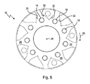
ワーリング工具10は、複数の切削プレート14a、14bが締結要素16を用いて解放可能に締結される切削プレートホルダ12を含む。切削プレート14a、14bは、好ましくは硬質金属製のリバーシブルの切削プレートである。締結要素16は、好ましくは、切削プレートホルダ12内に設けられたそれぞれのねじ山18に係合する締め付けねじとして実装される(図4および図5参照)。原則として、あらゆる種類の工具係合が考慮され得るが、締め付けねじ16には、好ましくは、トルクス(登録商標)工具係合または六角形ソケット工具係合が設けられる。切削プレートホルダ12は、好ましくは鋼製である。上記切削プレートホルダ12は、(単一の一体部品から)一体的に、または複数の部品において(複数の相互結合された部品から)構成することができる。
The
ここに示す本実施形態によるワーリング工具10は、全部で9つの切削プレート14a、14bを有し、これら切削プレート14a、14bは、切削プレートホルダ12上に周方向20において配置されている。本発明によるワーリング工具10の代替的な例示的実施形態では、本発明の範囲から逸脱することなく、たとえば、3つ、6つ、または12個の切削プレート14a、14bを9つの切削プレート14a、14bの代わりに設けることもできる。しかしながら、原理的には、本発明による切削プレート14a、14bの数は、3または3の倍数に制限される。
The
図示の例示的な実施形態における本発明によるワーリング工具10は、外側ワーリング工具として具体化される。この種の外側ワーリング工具は、特に雄ねじを製造するのに役立つ。
The whirling
ワーリング工具10は、通常、周方向20において比較的高い回転速度で駆動される。工具刃先の切削面が設定されるように、またはねじピッチが設定されるように、回転中の切削プレートホルダ12は、ワークピースに対して上記切削プレートホルダ12のx軸を中心として所望の角度だけ傾斜している。ワークピース(図示せず)は同様に、その長手方向軸を中心に回転するが、回転速度はワーリング工具10よりも実質的に低い。加工中、ワークピースは、切削プレートホルダ12の中心にくるように設けられた通路開口22を通じて、その長手方向に沿って押し込まれる。しかし、この送り動作中のワークピースは、ワーリング工具10の通路開口22内で、中心ではなく、偏心してまたは中心外に位置決めされる。ワーリングに一般的な動力学は、それを考慮に入れてもたらされる。ワークピースに対するワーリング工具10の偏心および傾斜配置によって、例えば、回しフライス削りとは対照的に、すべての切削プレート14a、14bが同時にワークピースに係合するのではなく、切削プレート14a、14bのうちの一部または1つのみが、任意の瞬間にワークピースに係合することが、本発明においては特に一般的である。従って、切削プレート14a、14bは、時間的に連続的にワークピースに接触する。
The
このような外側ワーリング工具に典型的な様式において、切削プレートホルダ12は、上述の理由により、加工中にワークピースを誘導可能である中心貫通孔22を有する。この通路開口22は、好ましくは、ワーリング工具10の長手方向軸24に対して対称である。本例示的実施形態における通路開口22は、円筒状に設計されている。ただし、これは必須ではない。原理的には他の形状も考えられる。しかし、切削プレートホルダ12は、図示された例示的な実施形態からも導かれ得るように、必ずしも長手方向軸24に対して対称である必要はない。
In a manner typical of such an outer Waring tool, the cutting
各切削プレート14a、14bは、切削プレートホルダ12にそのために設けられた切削プレート受け26の中に個々に配置される。これらの切削プレート受け26の各々は、平面状支持面28と、2つの互いに離間した接触面30,32とを有する(図4および図5参照)。図4および図5から分かるように、個々の切削プレート受け26の支持面28は、互いへと移行することが好ましい。従って、上記支持面28は、互いに同一平面上に、好ましくはワーリング工具10の長手方向軸24に直交するように位置合わせされる。しかし、2つの接触面30、32は、好ましくは、長手方向軸24と平行であり、従って、支持面28に直交するように整列されている。示されている例示的な実施形態における各切削プレート受け26の2つの接触面30,32は、互いに鋭角に整列している。これにより、切削プレート受け26内の切削プレート14a、14bの安定した着座が可能になる。
Each cutting
ワーリング工具10が組み立てられた状態の切削プレート14、14bは、切削プレートホルダ12の通路開口22内に突出する(特に図2参照)。単一のタイプの切削プレートだけでなく、少なくとも2つの異なるタイプの切削プレート14a、14bが本発明に従って使用されるため、上記切削プレート14a、14bは異なって、切削プレートホルダ12の通路開口22内に大きく突出する。切削プレート14a、14b、または切削プレート14a、14bの刃先の異なる軌道34,36が、それぞれそこから生じる。本発明によるワーリング工具10のこの特徴的な特徴の理由、またはそれから得られる利点について、それぞれ以下にさらにより詳細に説明する。
The cutting
本例示的実施形態では、それぞれ第1の種類または第1のタイプの1つの切削プレート14aまたはそれぞれ第1のタイプの切削プレート(詳細は図6参照)および第2の種類または第2のタイプの1つの切削プレート14b(詳細は図7参照)の異なる2種類の切削プレートが使用されている。
In the exemplary embodiment, each of the first type or first type of one
本発明によれば、異なる2種類の切削プレート14a、14bは、それらの全体的な幾何学的形状(寸法および/または形状)ならびにその刃先の寸法および/または形状によって互いに異なる。従って、上記切削プレート14a、14bは、その機能の点でも異なる。第1の種類の切削プレート14aは、特に輪郭を付与するために、または製造されるべきねじプロファイルを仕上げるために使用される。対照的に、第2の種類の切削プレート14bは、それぞれ主に荒削り(材料を減じる)または製造されるねじプロファイルの予備切削に使用される。
According to the present invention, the two different types of cutting
両方の切削プレートタイプ14a、14bは、それぞれ本体38aまたは38bと、それぞれ本体38aまたは38bから突出し、本体38aまたは38bと一体的に接続されているそれぞれ2つの切削体40aまたは40bとを有する。第1の種類の切削プレート14aの本体38aは、第2の種類の切削プレート14bの本体38bとまったく異ならず、または、(切削体に向かう移行部において)わずかだけ異なる。2つの切削プレートタイプ14a、14bの間の実質的な差異は、切削体40a、40bの異なる実施形態にある。
Both cutting
第1の種類の切削プレート14aの切削体40aは、第2の種類の切削プレート14bの切削体40bよりも大きくなるように設計されているか、または第2の種類の切削プレート14bの切削体40bよりも大きな体積を有するように設計されていることが好ましい。第1の種類の切削プレート14aの切削体40aは主に、第2の種類の切削プレート14bの切削体40bよりも深くなるように設計されている。「より深い」という用語は、ここでは、第1の種類の切削プレート14aの切削体40aの前端部が、第2の種類の切削プレート14bの切削体40bの前端部よりも、本体38aから大きな間隔を有するものとして理解されるべきである。従って、ワーリング工具10の組み立て状態における第1の種類の切削プレート14aの刃先42aは、第2の種類の切削プレート14bよりもさらに切削プレートホルダ12の通路開口22内に突出している(図2)。従って、切削プレート14aの刃先42aの軌道34は、切削プレート14bの軌道36よりも小さく、すなわち、より小さい直径を有する。代わりに、第2の種類の切削プレート14bの切削体40bは、特に切削体40bの前端部の領域において、第1の種類の切削プレート14aの切削体40aよりも高くなるように設計されている。切削プレート14a、14b、またはそれぞれそれらの切削体40a、40bの高さは、取り付けられた状態で長手方向軸24と平行に測定される上記切削プレートまたは切削体の寸法であると理解される。
The cutting
切削プレート14a、14bは、必ずしも交互に切削プレートホルダ12上に配置されるのではなく、3つの切削プレートからなる(仮想)グループに配置されることが好ましく、ここで、3つの切削プレートからなる各グループは、第1の種類の2つの切削プレート14aと、第2の種類の1つの切削プレート14bとを含む。言い換えれば、第1の種類の各切削プレート14aは、第1の種類の1つの他の切削プレート14aと第2の種類の1つの切削プレート14bとの間で切削プレートホルダ12上に配置される。これにより、第2の種類の切削プレート14bは、ねじ切りセグメントを予備的に切削し、ワーリング工具10の回転方向20に直接後続する第1の種類の2つの切削プレート14aは、ねじ切りセグメントの切削を完了し、ねじプロファイルを仕上げる。特に、回転方向20において各切削プレート14bに1つおきに後続する切削プレート14aは、それを考慮しすると最小限に応力を受ける。従って、上記切削プレート14aの摩耗は、切削プレート14bの摩耗よりも小さい。しかし、上記切削プレート14aが形成されるねじ山の実際の輪郭を付与するため、切削プレート14b、および、回転方向20において切削プレート14bに直接後続する切削プレート14aが摩耗する場合にも、比較的肯定的な加工結果を依然として達成することができる。従って、切削プレート14b、および、回転方向20において切削プレート14bに直接後続する切削プレート14aの摩耗は、容易に受け入れることができ、これによって、生成されるべきねじ山の表面品質が知覚可能に損なわれることはない。従って、すべての切削プレート14a、14bの全体的な寿命の延長を実現することができる。
The cutting
最後に、上記のような複数の異なる種類の切削プレートの原理は、内側ワーリング工具の場合にも本発明による方法で使用することができることに留意されたい。各事例において2つの切削体40a、40bを有する切削プレート14a、14b(いわゆる二重カッタ)の代わりに、1つのみの切削体を有する切削プレート(いわゆるシングルカッタ)または3つ以上の切削体を有する切削プレート(例えば、三重カッタまたは四重カッタ)も、原則として本発明の範囲から逸脱することなく使用することができる。原則として、3つの異なる種類の切削プレートを使用することもできる。個々の刃先42a、42bの幾何学的実施形態は、同様に、図に示された形状に限定されない。
Finally, it should be noted that the principles of several different types of cutting plates as described above can also be used in the method according to the invention in the case of an inner whirling tool. Instead of cutting
Claims (11)
複数の切削プレート受け(26)を有する切削プレートホルダ(12)であって、前記切削プレート受け(26)の各々は、前記切削プレート(14a、14b)の1つを受け入れるように構成され、前記切削プレート受け(26)は、前記切削プレートホルダ(12)にわたって周方向(20)に分布するように配置される、切削プレートホルダ(12)と、
前記切削プレートホルダ(12)の前記切削プレート受け(26)に前記切削プレート(14a、14b)を解放可能に締結するための複数の締結要素(16)と
を有する、ワークピースを加工するためのワーリング工具(10)であって、
前記切削プレート(14a、14b)は、2種類の異なる切削プレート(14a、14b)を含み、
前記切削プレートホルダ(12)上で互いに隣接して配置される3つの切削プレート(14a、14b)の各グループは、第1の種類の2つの切削プレート(14a)と、第2の種類の1つの切削プレート(14b)とを含み、
第1の種類の2つの切削プレート(14a)の一方は、切削プレートホルダ(12)上にて、第1の種類の2つの切削プレート(14a)の他方と、第2の種類の切削プレート(14b)との間に配置され、
前記第1の種類の2つの切削プレート(14a)は、全体的な幾何学的形状、及び刃先(42a、42b)の形状によって、前記第2の種類の切削プレート(14b)とは異なる、ワーリング工具(10)。 3 or multiple 3 cutting plates (14a, 14b), each cutting plate (14a, 14b) comprising at least one cutting edge (42a, 42b), ,
A cutting plate holder (12) having a plurality of cutting plate receivers (26), each of the cutting plate receivers (26) being configured to receive one of the cutting plates (14a, 14b); The cutting plate holder (26) is disposed so as to be distributed in the circumferential direction (20) over the cutting plate holder (12),
A plurality of fastening elements (16) for releasably fastening the cutting plates (14a, 14b) to the cutting plate receiver (26) of the cutting plate holder (12). Waring tool (10),
The cutting plates (14a, 14b) include two different types of cutting plates (14a, 14b),
Each group of three cutting plates (14a, 14b) arranged adjacent to each other on the cutting plate holder (12) includes two cutting plates (14a) of the first type and one of the second type. Two cutting plates (14b) ,
One of the two cutting plates (14a) of the first type is arranged on the cutting plate holder (12) with the other of the two cutting plates (14a) of the first type and the second type of cutting plate ( 14b), and
The two cutting plates (14a) of the first type are different from the cutting plate (14b) of the second type depending on the overall geometric shape and the shape of the cutting edges (42a, 42b). Tool (10).
第2の種類の切削プレート(14b)は、第2の本体(38b)と該第2の本体(38b)に一体的に接続された第2の切削体(40b)を備え、第2の切削体(40b)は第2の本体(38b)から突出し、第2の種類の切削プレート(14b)の刃先(42b)は、第2の切削体(40b)上に配置され、第1の切削体(40a)は、第2の切削体(40b)よりも体積が大きい、請求項1に記載のワーリング工具。 Each of the two cutting plates (14a) of the first type includes a first body (38a) and a first cutting body (40a) integrally connected to the first body (38a). The first cutting body (40a) protrudes from the first body (38a), and the cutting edges (42a) of the two cutting plates (14a) of the first type are the two cutting plates of the first type. (14a) on each first cutting body (40a) ,
The second type of cutting plate (14b) includes a second main body (38b) and a second cutting body (40b) integrally connected to the second main body (38b). The body (40b) protrudes from the second body (38b), and the cutting edge (42b) of the second type of cutting plate (14b) is disposed on the second cutting body (40b) , and the first cutting body The Waring tool according to claim 1, wherein (40a) has a larger volume than the second cutting body (40b).
Applications Claiming Priority (3)
| Application Number | Priority Date | Filing Date | Title |
|---|---|---|---|
| DE102015115310.6A DE102015115310A1 (en) | 2015-09-10 | 2015-09-10 | whirling tool |
| DE102015115310.6 | 2015-09-10 | ||
| PCT/EP2016/070452 WO2017042061A1 (en) | 2015-09-10 | 2016-08-31 | Whirling tool |
Publications (2)
| Publication Number | Publication Date |
|---|---|
| JP2018526235A JP2018526235A (en) | 2018-09-13 |
| JP6568307B2 true JP6568307B2 (en) | 2019-08-28 |
Family
ID=56893950
Family Applications (1)
| Application Number | Title | Priority Date | Filing Date |
|---|---|---|---|
| JP2018512905A Active JP6568307B2 (en) | 2015-09-10 | 2016-08-31 | Waring tool |
Country Status (7)
| Country | Link |
|---|---|
| US (2) | US10549366B2 (en) |
| EP (1) | EP3347154A1 (en) |
| JP (1) | JP6568307B2 (en) |
| CN (1) | CN108136526B (en) |
| DE (1) | DE102015115310A1 (en) |
| RU (1) | RU2698023C1 (en) |
| WO (1) | WO2017042061A1 (en) |
Families Citing this family (6)
| Publication number | Priority date | Publication date | Assignee | Title |
|---|---|---|---|---|
| DE102015115310A1 (en) | 2015-09-10 | 2017-03-16 | Hartmetall-Werkzeugfabrik Paul Horn Gmbh | whirling tool |
| DE102017127307A1 (en) * | 2017-11-20 | 2019-05-23 | Hartmetall-Werkzeugfabrik Paul Horn Gmbh | whirling tool |
| DE202017007546U1 (en) | 2017-11-20 | 2022-07-25 | Hartmetall-Werkzeugfabrik Paul Horn Gmbh | swirl tool |
| DE102017130056A1 (en) | 2017-12-14 | 2019-06-19 | Mirko Flam | whirling unit |
| DE202017107633U1 (en) | 2017-12-14 | 2019-03-18 | Mirko Flam | whirling unit |
| CH714283B1 (en) | 2017-12-18 | 2019-04-30 | Willen Pcm Sa | Vortex device. |
Family Cites Families (56)
| Publication number | Priority date | Publication date | Assignee | Title |
|---|---|---|---|---|
| US1855511A (en) * | 1924-07-16 | 1932-04-26 | Barber Colman Co | Milling cutter |
| US1883334A (en) * | 1930-08-16 | 1932-10-18 | William A Neracher | Diestock |
| US1906176A (en) * | 1931-01-16 | 1933-04-25 | Landis Machine Co | Chaser |
| US2174467A (en) * | 1936-07-30 | 1939-09-26 | Nat Tube Co | Nonrhythmic thread cutting die and method of producing nonsinuous threads |
| US2152567A (en) * | 1937-07-03 | 1939-03-28 | Landis Machine Co | Chaser for die heads |
| US2517062A (en) * | 1945-02-17 | 1950-08-01 | Richard W Vosper | Die head |
| SU568509A1 (en) * | 1976-04-29 | 1977-08-15 | Предприятие П/Я А-7755 | Vortex head for rapid cutting of small-diameter continuous non-rigidhelical surfaces |
| SU650743A1 (en) * | 1976-11-09 | 1979-03-05 | Киевский Ордена Ленина Политехнический Институт Им. 50-Летия Великой Октябрьской Социалистической Революции | Device for vortical cutting of inner thread |
| SU768579A1 (en) * | 1978-11-30 | 1980-10-07 | Московское Ордена Ленина И Ордена Трудового Красного Знамени Высшее Техническое Училище Им. Н. Э.Баумана | Apparatus for threading screws |
| DD141636A1 (en) * | 1979-03-26 | 1980-05-14 | Karl Janata | METHOD AND TOOL FOR PRODUCING THREADED PROFILES |
| US4576527A (en) * | 1983-07-21 | 1986-03-18 | Barber-Colman Company | Shaper cutter |
| US4522538A (en) * | 1983-11-07 | 1985-06-11 | Lindsay Harold W | Milling cutter with multiple indexable cutting inserts |
| US4784538A (en) * | 1985-07-30 | 1988-11-15 | Fellows Corporation | Disposable disk cutter |
| US4674923A (en) * | 1985-08-09 | 1987-06-23 | Ratemaker Tools, Inc. | Access notches for indexing inserts in a groove mill |
| DE3532282A1 (en) * | 1985-09-11 | 1987-03-19 | Gwt Ges Fuer Gewindewirbel & T | Apparatus for the whirling or paring of threads, worms and profiles |
| US4640159A (en) * | 1985-11-22 | 1987-02-03 | Stojan Stojanovski | Tool holder with plurality of cutting inserts |
| US4997018A (en) * | 1990-06-25 | 1991-03-05 | Commercial Knife, Inc. | Mounted knife system |
| US5098231A (en) * | 1991-03-19 | 1992-03-24 | Haug Edward W | Shaper cutter with disposable spring type insert |
| JPH1058233A (en) * | 1996-08-26 | 1998-03-03 | Dainichi Kinzoku Kogyo Kk | Tool holder for whirling machining device |
| AU4651100A (en) * | 1999-04-19 | 2000-11-02 | Jeffrey D. Russell | Cutting tool |
| IL129665A (en) * | 1999-04-29 | 2008-06-05 | Rafael Morgulis | Cutting tool assembly and cutting insert therefor |
| DE19929068A1 (en) * | 1999-06-25 | 2000-12-28 | Leistritz Ag | Vortex ring for paring external threads, worms and profiles has vortex ring with several equally spaced clamping holders for paring tools set in two axially spaced planes to produce twin-thread worms in one work step |
| JP2001121351A (en) * | 1999-10-25 | 2001-05-08 | Oooka Seisakusho:Kk | Cutting method, cutting material and cutting device |
| SE523755C2 (en) * | 2002-02-22 | 2004-05-11 | Seco Tools Ab | Cutting tools and holders |
| US7059810B2 (en) * | 2002-04-18 | 2006-06-13 | Kennametal Inc. | Gear hobbing cutter system |
| US6877934B2 (en) * | 2002-10-28 | 2005-04-12 | Rem Sales, Inc. | Milling head for thread whirling |
| SE526037C2 (en) * | 2003-02-06 | 2005-06-21 | Sandvik Ab | Chip separator machining tool for rotary machining and turning |
| BRPI0416195A (en) * | 2003-11-04 | 2007-01-16 | Mitsubishi Materials Corp | disposable insert pin and disposable mirror cutter |
| ES2331181T3 (en) * | 2003-12-03 | 2009-12-23 | Metso Paper, Inc. | KNIFE SETTING METHOD. |
| DE102006028729A1 (en) * | 2006-06-20 | 2007-12-27 | Komet Group Holding Gmbh | Machine tool and cutting ring for a machine tool |
| KR20080026027A (en) * | 2006-09-19 | 2008-03-24 | 유틸리스 아게 | Thread-whirling tool |
| MX2009009007A (en) * | 2007-02-26 | 2010-01-20 | Greenleaf Technology Corp | Slotting cutter and inserts for same. |
| ITGE20070032A1 (en) * | 2007-03-14 | 2008-09-15 | Ts Tecnospamec S R L | CUTTING TOOL. |
| JP2008296331A (en) * | 2007-05-31 | 2008-12-11 | Nsk Ltd | Machining device |
| US20090041553A1 (en) * | 2007-08-06 | 2009-02-12 | 3M Innovative Properties Company | Fly-cutting system and method, and related tooling and articles |
| RU76267U1 (en) * | 2008-05-04 | 2008-09-20 | Открытое акционерное общество "Станкон" | SWIRL HEAD |
| US8905682B2 (en) * | 2009-02-11 | 2014-12-09 | Simatate Ltd. | Multi-edge cutting head and an insert used therein |
| CN102665583B (en) * | 2009-12-25 | 2014-01-01 | 日本特殊陶业株式会社 | Screw manufacturing method, whirling cutter, and screw manufacturing machine |
| ES2375392B1 (en) * | 2010-08-17 | 2012-10-10 | Fermín Arias Sucarrats | DEVICE FOR MILLING AND POLISHING OF METACRYLATE OR TRANSPARENT PLASTICS. |
| DE102011013789B3 (en) * | 2011-03-02 | 2012-06-14 | Hartmetall-Werkzeugfabrik Paul Horn Gmbh | die stock |
| US8647023B2 (en) * | 2011-04-04 | 2014-02-11 | Kennametal Inc. | Clamping mechanism for slotting cutter |
| DE102011016921A1 (en) * | 2011-04-13 | 2012-10-18 | Kennametal Inc. | Cutting plate carrier |
| US9216461B2 (en) * | 2011-07-19 | 2015-12-22 | Iscar, Ltd. | Cutting body configured for fine-tuning and metal-working machine tool comprising a plurality thereof |
| US8905684B2 (en) * | 2012-06-22 | 2014-12-09 | Kennametal Inc. | Slotting cutter, cutting insert and tool therefor |
| DE102013103089B3 (en) * | 2013-03-26 | 2014-05-08 | Hartmetall-Werkzeugfabrik Paul Horn Gmbh | die stock |
| EP2815837B1 (en) * | 2013-06-19 | 2018-09-05 | Klingelnberg AG | Cutting head and use of the same |
| DE102013107858B4 (en) * | 2013-07-23 | 2023-03-16 | Kennametal Inc. | Tool for turn-turn broaching of workpieces |
| US9475138B2 (en) * | 2014-01-22 | 2016-10-25 | Kennametal Inc. | Cutting tool having insert pocket with cantilevered member |
| CN105813787B (en) * | 2014-05-15 | 2018-05-15 | 株式会社泰珂洛 | Blade installing mechanism, rotary cutting tool, tool body, chock component and adjustment component |
| CN203992686U (en) * | 2014-06-11 | 2014-12-10 | 马钢(集团)控股有限公司 | Adjustable major diameter external screw thread reason button device |
| EP2965847B1 (en) * | 2014-07-09 | 2019-09-11 | Sandvik Intellectual Property AB | Cutting insert and power skiving tool |
| DE102015102044A1 (en) * | 2015-02-12 | 2016-08-18 | Kennametal Inc. | Milling tool and cutting insert for such a milling tool |
| US20160339530A1 (en) * | 2015-05-22 | 2016-11-24 | Caterpillar Inc. | Double Tooth Gap Cutter and Associated Cutting Insert |
| US20170014922A1 (en) * | 2015-07-15 | 2017-01-19 | Caterpillar Inc. | Power Skiving Assembly and Method of Operation of Same |
| US10183347B2 (en) * | 2015-09-08 | 2019-01-22 | Iscar, Ltd. | Rotary cutting tool having axial position adjustment arrangement |
| DE102015115310A1 (en) | 2015-09-10 | 2017-03-16 | Hartmetall-Werkzeugfabrik Paul Horn Gmbh | whirling tool |
-
2015
- 2015-09-10 DE DE102015115310.6A patent/DE102015115310A1/en active Pending
-
2016
- 2016-08-31 RU RU2018112523A patent/RU2698023C1/en active
- 2016-08-31 JP JP2018512905A patent/JP6568307B2/en active Active
- 2016-08-31 EP EP16763227.2A patent/EP3347154A1/en active Pending
- 2016-08-31 WO PCT/EP2016/070452 patent/WO2017042061A1/en active Application Filing
- 2016-08-31 CN CN201680052376.4A patent/CN108136526B/en active Active
-
2018
- 2018-03-05 US US15/911,447 patent/US10549366B2/en active Active
-
2019
- 2019-12-04 US US16/703,422 patent/US11559844B2/en active Active
Also Published As
| Publication number | Publication date |
|---|---|
| CN108136526A (en) | 2018-06-08 |
| CN108136526B (en) | 2019-08-27 |
| RU2698023C1 (en) | 2019-08-21 |
| JP2018526235A (en) | 2018-09-13 |
| EP3347154A1 (en) | 2018-07-18 |
| WO2017042061A1 (en) | 2017-03-16 |
| DE102015115310A1 (en) | 2017-03-16 |
| US11559844B2 (en) | 2023-01-24 |
| US20180193934A1 (en) | 2018-07-12 |
| US10549366B2 (en) | 2020-02-04 |
| US20200101545A1 (en) | 2020-04-02 |
Similar Documents
| Publication | Publication Date | Title |
|---|---|---|
| JP6568307B2 (en) | Waring tool | |
| JP5475808B2 (en) | Rotating tools and cutting inserts for cutting | |
| RU2648717C2 (en) | Rotary cutting tool and reversible cutting insert thereof | |
| EP2659999A2 (en) | A milling tool as well as set of milling inserts of a milling tool | |
| US10328503B2 (en) | T-slot cutter | |
| JP2013000883A (en) | Milling tool, and segment | |
| KR102320629B1 (en) | Star-shaped cutting inserts for front and rear chamfering rotary milling cutters | |
| US9796028B2 (en) | Prismatic and cylindrical cutting inserts | |
| US10384276B2 (en) | Insert type tool and thread mill | |
| US10010332B2 (en) | Cutting tool and corresponding assembly | |
| JP6737904B2 (en) | Cutting inserts and tools for machining | |
| RU2424090C2 (en) | End milling cutter | |
| US11045889B2 (en) | Thread milling cutter and internal pipe thread machining method using the same | |
| JP2005040941A (en) | Milling cutter with tangentially mounted insert | |
| US20220266364A1 (en) | Tool and method for machining a workpiece | |
| JP6752154B2 (en) | Threaded milling cutter | |
| JP2021510638A (en) | Power skiving tool | |
| WO2010101512A2 (en) | Method of thread milling, thread, and insert and tool for thread milling | |
| JP2015208835A (en) | Cutting edge replaceable face milling cutter and manufacturing method of the same | |
| RU2807811C1 (en) | Prefabricated cutter | |
| US9782845B2 (en) | Indexable milling cutting insert | |
| WO2014129517A1 (en) | Rotating tool | |
| JP2010099794A (en) | Screw machining tool with interchangeable screw machining portion | |
| RU2253550C1 (en) | Method for stabilizing parameters of gear wheel teeth cut by means of builtup adjustable gear shaper | |
| KR20220051265A (en) | Method and device for deburring workpieces with internal teeth |
Legal Events
| Date | Code | Title | Description |
|---|---|---|---|
| A521 | Request for written amendment filed |
Free format text: JAPANESE INTERMEDIATE CODE: A523 Effective date: 20180511 |
|
| A621 | Written request for application examination |
Free format text: JAPANESE INTERMEDIATE CODE: A621 Effective date: 20180601 |
|
| A131 | Notification of reasons for refusal |
Free format text: JAPANESE INTERMEDIATE CODE: A131 Effective date: 20190305 |
|
| A977 | Report on retrieval |
Free format text: JAPANESE INTERMEDIATE CODE: A971007 Effective date: 20190228 |
|
| TRDD | Decision of grant or rejection written | ||
| A01 | Written decision to grant a patent or to grant a registration (utility model) |
Free format text: JAPANESE INTERMEDIATE CODE: A01 Effective date: 20190709 |
|
| A61 | First payment of annual fees (during grant procedure) |
Free format text: JAPANESE INTERMEDIATE CODE: A61 Effective date: 20190801 |
|
| R150 | Certificate of patent or registration of utility model |
Ref document number: 6568307 Country of ref document: JP Free format text: JAPANESE INTERMEDIATE CODE: R150 |
|
| R157 | Certificate of patent or utility model (correction) |
Free format text: JAPANESE INTERMEDIATE CODE: R157 |
|
| R250 | Receipt of annual fees |
Free format text: JAPANESE INTERMEDIATE CODE: R250 |
|
| R250 | Receipt of annual fees |
Free format text: JAPANESE INTERMEDIATE CODE: R250 |