JP6567893B2 - Interior member mounting structure - Google Patents
Interior member mounting structure Download PDFInfo
- Publication number
- JP6567893B2 JP6567893B2 JP2015128486A JP2015128486A JP6567893B2 JP 6567893 B2 JP6567893 B2 JP 6567893B2 JP 2015128486 A JP2015128486 A JP 2015128486A JP 2015128486 A JP2015128486 A JP 2015128486A JP 6567893 B2 JP6567893 B2 JP 6567893B2
- Authority
- JP
- Japan
- Prior art keywords
- clip
- surface portion
- seat
- interior member
- vehicle body
- Prior art date
- Legal status (The legal status is an assumption and is not a legal conclusion. Google has not performed a legal analysis and makes no representation as to the accuracy of the status listed.)
- Active
Links
- 235000021189 garnishes Nutrition 0.000 description 8
- 239000005357 flat glass Substances 0.000 description 4
- 230000000694 effects Effects 0.000 description 2
- 229920003002 synthetic resin Polymers 0.000 description 2
- 239000000057 synthetic resin Substances 0.000 description 2
- 206010039203 Road traffic accident Diseases 0.000 description 1
- 208000027418 Wounds and injury Diseases 0.000 description 1
- 238000001514 detection method Methods 0.000 description 1
- 230000006866 deterioration Effects 0.000 description 1
- 230000001747 exhibiting effect Effects 0.000 description 1
- 230000002452 interceptive effect Effects 0.000 description 1
- 239000002184 metal Substances 0.000 description 1
Images


Landscapes
- Vehicle Interior And Exterior Ornaments, Soundproofing, And Insulation (AREA)
- Air Bags (AREA)
Description
本発明は内装部材取付構造に関し、特に、その内部にエアバッグを介在させ、内装部材を車体部材に取り付ける内装部材取付構造に関する。 The present invention relates to an interior member mounting structure, and more particularly, to an interior member mounting structure in which an airbag is interposed therein and an interior member is attached to a vehicle body member.
一般に、自動車のボディでは、ルーフパネルを複数のピラーで支持しており、金属板から成るピラーの内側はピラートリムで被覆されている。このピラートリムは、一般的に板状の合成樹脂から構成されており、車室側の意匠性を向上させるとともに、乗員を保護する役割も有している。また、近年に於いては、事故発生時に乗員を保護する効果を大きくするために、ピラーとピラートリムとの間隙にカーテンエアバッグを備えたものも登場してきている。 In general, in an automobile body, a roof panel is supported by a plurality of pillars, and an inner side of a pillar made of a metal plate is covered with a pillar trim. The pillar trim is generally made of a plate-shaped synthetic resin, and improves the design of the passenger compartment and also protects the passenger. In recent years, in order to increase the effect of protecting an occupant in the event of an accident, there has been an apparatus having a curtain airbag in the gap between the pillar and the pillar trim.
特許文献1には、この種のピラートリムの取付構造が開示されている。図5を参照して、フロントウィンドウガラス200とフロントドアウィンドウガラス202との間に、フロントピラー204が配置されている。また、フロントピラー204の内側部分は、フロントピラートリム208で被覆されており、フロントピラートリム208の内壁には固定用のクリップ取付台210が形成されている。フロントピラー204とフロントピラートリム208との間隙にはエアバッグ212が畳まれた状態で収納されている。フロントピラー204と、フロントピラートリム208のクリップ取付台210とは、両者に嵌合挿入されたクリップ206で結合されている。また、クリップ206の内側先端部には、エアバッグ212が展開する際のフロントピラートリム208の浮き上がりを抑制する移動係止部位214が形成されている。
衝突発生時には、車両に取り付けされた図示しない振動センサの出力に基づいて、図示しないインフレータが作動し、インフレータから発生する気体をエアバッグ212に注入する。これにより、エアバッグ212は車室側面に沿って下方に膨張展開する。これにより、車両に搭乗する乗員と車体側面との間にエアバッグが存在することとなり、事故発生時における乗員の安全性が向上される。
When a collision occurs, an inflator (not shown) operates based on the output of a vibration sensor (not shown) attached to the vehicle, and gas generated from the inflator is injected into the
特許文献2には、同様にカーテンエアバックを備えたガーニッシュの取付構造において、装着を簡易にした取付クリップの構成が記載されている。具体的には、図6を参照して、ガーニッシュ本体300の上面には支持台部302が形成されており、この支持台部302に上面から、取付クリップ306が挿入されている。支持台部302の内部には、傾斜する当接案内部308が形成されており、支持台部302に取付クリップ306を挿入する際に、取付クリップ306の先端に設けた可撓支持部304が当接案内部308に接触して曲折する。従って、取り付け時に於いて、取付クリップ306の可撓支持部304が、ガーニッシュ本体300の内面に強く押し付けられることが抑制され、可撓支持部304の劣化が防止されている。
Patent Document 2 describes a configuration of a mounting clip that is easily mounted in a garnish mounting structure similarly provided with a curtain airbag. Specifically, referring to FIG. 6, a
特許文献3にも、ガーニッシュを取り付けるためのクリップの構成が記載されている。図7を参照して、ガーニッシュ本体404の上面には、略箱形状の取付座402が形成されており、取付座402の上面からクリップ400が挿入されている。クリップ400を、取付座402に挿入する際には、クリップ400の先端部であるアンカー部406が、傾斜する案内面408に沿って案内されることにより、屈曲される。これにより、クリップ400のガーニッシュ本体404への取付が容易とされる。
Patent Document 3 also describes the configuration of a clip for attaching a garnish. Referring to FIG. 7, a substantially box-
しかしながら、上記した特許文献1に記載れた発明では、図5を参照して、衝突事故発生時にエアバッグ212が膨張展開する際に、エアバッグ212の展開が阻害される恐れがあった。具体的には、エアバッグ212が膨張展開する際には、エアバッグ212は紙面上にて下方向に向かって展開しようとする。一方、フロントピラートリム208は、クリップ206により紙面上にて横方向に係止されているので、エアバッグ212の展開時にはフロントピラートリム208は右方向に移動しようとする。よって、エアバッグ212の展開方向と、フロントピラートリム208の移動方向が相違するので、エアバッグ212が良好に展開しない恐れがある課題があった。
However, in the invention described in
かかる課題は、上記した特許文献2および特許文献3も同様であり、事故発生時においてクリップが外れる方向が、エアバッグの膨張展開方向と異なるので、これらの文献に記載された発明も上記した課題を有していた。 This problem is the same in Patent Document 2 and Patent Document 3 described above, and the direction in which the clip is removed when an accident occurs differs from the inflation and deployment direction of the airbag. Therefore, the inventions described in these documents also include the above-described problem. Had.
本発明は、このような問題点を鑑みてなされたものであり、本発明の目的は、衝突発生時にエアバッグを確実に膨張展開させることが出来る内装部材取付構造を提供することにある。 The present invention has been made in view of such problems, and an object of the present invention is to provide an interior member mounting structure that can reliably inflate and deploy an airbag when a collision occurs.
本発明の内装部材取付構造は、車体部材を内側から被覆する内装部材と、 前記車体部材と前記内装部材との間に形成された空間に、畳まれた状態で収納されるエアバッグと、 一方の端部側が前記車体部材に挿入嵌合され、他方の端部側が前記内装部材の内壁に形成されたクリップ座に挿入嵌合されるクリップと、を備え、 前記クリップ座は、前記内装部材の内壁から前記車体部材に向かって伸びて互いに対向する第1側面部および第2側面部と、前記第1側面部および前記第2側面部と連続すると共に前記車体部材と対向する対向面部と、を有し、 前記クリップ座に、前記エアバッグの側に向かって伸び、且つ、前記第1側面部、前記対向面部および前記第2側面部に渡って形成される孔部を設け、前記孔部に前記クリップを挿入嵌合し、前記エアバッグが膨張展開する際に、前記内装部材は前記車体部材から離間すると共に、前記クリップが前記クリップ座に係合することを特徴とする。
An interior member mounting structure of the present invention includes an interior member that covers a vehicle body member from the inside, an airbag that is stored in a folded state in a space formed between the vehicle body member and the interior member, A clip seat that is inserted and fitted to the vehicle body member, and the other end side is inserted and fitted to a clip seat formed on the inner wall of the interior member. A first side surface portion and a second side surface portion that extend from an inner wall toward the vehicle body member and face each other; and a facing surface portion that is continuous with the first side surface portion and the second side surface portion and faces the vehicle body member. The clip seat is provided with a hole extending toward the airbag side and formed over the first side surface portion, the opposing surface portion, and the second side surface portion; inserting fitting the clip, When the airbag is inflated and deployed, the interior member is separated from the vehicle body member, and the clip is engaged with the clip seat .
更に、本発明の内装部材取付構造は、前記クリップは、前記車体部材側に挿入されて係止される車体部材係止部と、前記内装部材の前記クリップ座に挿入されて係止される内装部材係止部と、を有し、前記クリップ座の前記側面部に形成される前記孔部の幅は、前記クリップの前記内装部材係止部の幅よりも長いことを特徴とする。 Furthermore, in the interior member mounting structure according to the present invention, the clip is inserted into the vehicle body member side to be locked and a vehicle body member locking portion, and the interior is inserted and locked into the clip seat of the interior member. A width of the hole formed in the side surface portion of the clip seat is longer than a width of the interior member locking portion of the clip.
更に、本発明の内装部材取付構造は、前記クリップは、前記クリップ座と当接する取付座面部を有し、前記クリップの前記取付座面部には、外側に向かって前記内装部材側に傾斜する第1傾斜面部位が形成され、前記クリップ座の前記対向面部の両端部を傾斜形状に形成することで、第2斜面部を形成することを特徴とする。 Furthermore, in the interior member mounting structure of the present invention, the clip has a mounting seat surface portion that comes into contact with the clip seat, and the mounting seat surface portion of the clip is inclined toward the interior member side toward the outside. One inclined surface portion is formed, and the second inclined surface portion is formed by forming both end portions of the facing surface portion of the clip seat in an inclined shape.
本発明の内装部材取付構造は、車体部材を内側から被覆する内装部材と、 前記車体部材と前記内装部材との間に形成された空間に、畳まれた状態で収納されるエアバッグと、 一方の端部側が前記車体部材に挿入嵌合され、他方の端部側が前記内装部材の内壁に形成されたクリップ座に挿入嵌合されるクリップと、を備え、 前記クリップ座は、前記内装部材の内壁から前記車体部材に向かって伸びて互いに対向する第1側面部および第2側面部と、前記第1側面部および前記第2側面部と連続すると共に前記車体部材と対向する対向面部と、を有し、 前記クリップ座に、前記エアバッグの側に向かって伸び、且つ、前記第1側面部、前記対向面部および前記第2側面部に渡って形成される孔部を設け、前記孔部に前記クリップを挿入嵌合し、前記エアバッグが膨張展開する際に、前記内装部材は前記車体部材から離間すると共に、前記クリップが前記クリップ座に係合することを特徴とする。従って、交通事故が発生した際に、エアバックが展開しようとすると、クリップ座に形成された孔部に沿ってクリップがスムーズに移動するので、エアバッグとクリップ座とが接触することにより、内装部材の展開が阻害されることが抑止される。
An interior member mounting structure of the present invention includes an interior member that covers a vehicle body member from the inside, an airbag that is stored in a folded state in a space formed between the vehicle body member and the interior member, A clip seat that is inserted and fitted to the vehicle body member, and the other end side is inserted and fitted to a clip seat formed on the inner wall of the interior member. A first side surface portion and a second side surface portion that extend from an inner wall toward the vehicle body member and face each other; and a facing surface portion that is continuous with the first side surface portion and the second side surface portion and faces the vehicle body member. The clip seat is provided with a hole extending toward the airbag side and formed over the first side surface portion, the opposing surface portion, and the second side surface portion; inserting fitting the clip, When the airbag is inflated and deployed, the interior member is separated from the vehicle body member, and the clip is engaged with the clip seat . Therefore, when an air bag tries to deploy in the event of a traffic accident, the clip moves smoothly along the hole formed in the clip seat. It is suppressed that the expansion | deployment of a member is inhibited.
更に、本発明の内装部材取付構造は、前記クリップは、前記車体部材側に挿入されて係止される車体部材係止部と、前記内装部材の前記クリップ座に挿入されて係止される内装部材係止部と、を有し、前記クリップ座の前記側面部に形成される前記孔部の幅は、前記クリップの前記内装部材係止部の幅よりも長いことを特徴とする。従って、クリップ座の側面部位に形成された孔部の幅が、クリップの内装部材係止部よりも広く形成されることにより、エアバックが膨張展開する際に、クリップが更に容易にクリップ座から離脱しやすく成る。 Furthermore, in the interior member mounting structure according to the present invention, the clip is inserted into the vehicle body member side to be locked and a vehicle body member locking portion, and the interior is inserted and locked into the clip seat of the interior member. A width of the hole formed in the side surface portion of the clip seat is longer than a width of the interior member locking portion of the clip. Accordingly, the width of the hole formed in the side surface portion of the clip seat is formed wider than the interior member locking portion of the clip, so that when the airbag is inflated and deployed, the clip is more easily removed from the clip seat. It becomes easy to leave.
更に、本発明の内装部材取付構造は、前記クリップは、前記クリップ座と当接する取付座面部を有し、前記クリップの前記取付座面部には、外側に向かって前記内装部材側に傾斜する第1傾斜面部位が形成され、前記クリップ座の前記対向面部の両端部を傾斜形状に形成することで、第2斜面部を形成することを特徴とする。従って、クリップの第1傾斜面部と、クリップ座の第2傾斜面部とが当接することで、クリップとクリップ座とが良好に位置合わせされ、通常の使用状況下にて両者の相対的位置がずれることが防止される。 Furthermore, in the interior member mounting structure of the present invention, the clip has a mounting seat surface portion that comes into contact with the clip seat, and the mounting seat surface portion of the clip is inclined toward the interior member side toward the outside. One inclined surface portion is formed, and the second inclined surface portion is formed by forming both end portions of the facing surface portion of the clip seat in an inclined shape. Therefore, when the first inclined surface portion of the clip and the second inclined surface portion of the clip seat come into contact with each other, the clip and the clip seat are well aligned, and the relative positions of the two are shifted under normal use conditions. It is prevented.
以下、図を参照して、本形態のピラートリム取付構造(内装部材取付構造)を説明する。以下の説明では、上下前後左右の各方向を適宜用いて説明するが、左右方向は、車両の進行方向(前方)を向いた場合の左右方向を示している。 Hereinafter, the pillar trim mounting structure (interior member mounting structure) of this embodiment will be described with reference to the drawings. In the following description, description will be made using the vertical and horizontal directions as appropriate, but the horizontal direction indicates the horizontal direction when facing the traveling direction (front) of the vehicle.
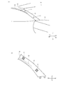
図1を参照して、本形態のピラートリム取付構造11の概略的構成を説明する。図1(A)は車両10の前端部を車体内から見た斜視図であり、図1(B)はピラートリム12を抜き出して示す図である。
With reference to FIG. 1, the schematic structure of the pillar
図1(A)を参照して、車両10の車室内前方端部には、車体の上方に配置される屋根部材を支えるフロントピラー(車体部材、ここでは図示しない)が備えられている。また、車室の前端部に配置されるインパネ16の左方端部から、フロントピラーを内側から覆うピラートリム12(内装部材)が備え付けされている。本形態では、車両前部に配置される所謂Aピラーに内側からピラートリム12を取り付ける構成に関して説明するが、車両10の中間部分や後部に配置されるBピラーやCピラーに対して固定されるピラートリム12に、本形態を適用することも可能である。また本形態が適用される内装部品としては、本形態ではピラートリム12を例示するが、天井トリム18等の他の内装部品に対して、本形態を適用することも可能である。
Referring to FIG. 1A, a front pillar (vehicle body member, not shown here) that supports a roof member disposed above the vehicle body is provided at the front end of the
カーテンエアバッグ20は、フロントピラーとピラートリム12との間に形成される空間に配置されており、この図では点線で示している。カーテンエアバッグ20は車両左端のサイドレールに沿って配設されており、その中間部分は天井トリム18により覆われている。カーテンエアバッグ20は、膨張展開時に展開するように、折り畳まれるか巻回された状態で配設されている。
The
カーテンエアバッグ20は次のように動作する。即ち、車両10に一定以上の衝突エネルギーが作用すると、車両10に内蔵された衝突検知センサ(図示しない)がその衝突を検出し、インフレータ(図示しない)を作動させる。その後、インフレータからカーテンエアバッグ20にガスが導入されることにより、カーテンエアバッグ20は下方向に膨張展開される。カーテンエアバッグ20の膨張展開に伴い、カーテンエアバッグ20の下方向への膨張展開を可能とするために、天井トリム18およびピラートリム12は、車体側から離脱するようになる。下方に向かって膨張展開したカーテンエアバッグ20が、車両10の内側側面と搭乗者との間に配置されることで、搭乗者の特に頭部が外部衝撃から保護されるようになる。
The
図1(B)を参照して、上記したピラートリム12は、フロントピラーに対してピラートリム取付構造11を介して取り付けされている。本形態では、ピラートリム12の長さ方向に沿って、複数のピラートリム取付構造11が形成されている。ピラートリム取付構造11の機能は、車両10が衝突していない通常時にはピラートリム12をフロントピラーに取り付け、車両10に衝突衝撃が生じた際には、カーテンエアバッグ20が良好に下方向に膨張展開するように、フロントピラーから離脱することにある。
Referring to FIG. 1B, the pillar trim 12 described above is attached to the front pillar via a pillar
図2を参照して、上記したピラートリム取付構造11の構成を詳述する。図2(A)はピラートリム取付構造11を示す断面図であり、図2(B)はクリップ座26を詳細に示す斜視図であり、図2(C)はテザークリップ14の構成を示す側面図である。なお、この図では、カーテンエアバッグ20が膨張展開する方向を下方向とし、その逆方向を上方向としている。
With reference to FIG. 2, the structure of the above-described pillar
図2(A)を参照して、ピラートリム取付構造11は、フロントピラー24と、フロントピラー24の内側側面を車室内から覆うピラートリム12と、フロントピラー24とピラートリム12との間に畳まれた状態で収納されるカーテンエアバッグ20と、ピラートリム12をフロントピラー24に係合させるテザークリップ14と、を主要に有している。
2A, the pillar
ピラートリム12の外側側面から、フロントピラー24側に向かって略箱状に突出したクリップ座26が形成されている。クリップ座26は、ピラートリム12と、一体的に射出成形された合成樹脂から成る。クリップ座26には、テザークリップ14のトリム係止部14Aが挿入嵌合される。クリップ座26には、溝状の孔部28が形成されており、テザークリップ14のトリム係止部14Aは、この孔部28に挿入嵌合されている。一方、テザークリップ14のピラー係止部14Bは、フロントピラー24に形成された孔部(ここでは不図示)に挿入嵌合されている。
A
カーテンエアバッグ20は、フロントピラー24とピラートリム12との間に形成される空間に於いて、クリップ座26の下方に配置されている。
The
図2(B)を参照して、上記したクリップ座26の構成を詳述する。クリップ座26は、上記したピラートリム12の外側側面(フロントピラー24に対向する面)から突出する4つの側面を有している。具体的には、この側面としては、上下方向で相対向する側面部26B、26Cと、前後方向で相対向する側面部26D、26Eとから構成されている。また、これらの側面と連続する対向面部26Aが形成されており、対向面部26Aは図2(A)に示すフロントピラー24と対面している。本形態では、クリップ座26には、テザークリップ14が挿通される孔部28が形成されているが、係る事項は後述する。
With reference to FIG. 2 (B), the structure of the
図2(C)を参照して、テザークリップ14は、内側から、移動係止部14Cと、トリム係止部14A(内装部材係止部)と、座面部14D、14Eと、ピラー係止部14B(車体部材係止部)と、から構成されている。
2C, the
移動係止部14Cは、その先端部が中間部よりも太く形成される拡径部とされており、かかる拡径部がクリップ座26に係合する働きを有している。
14 C of movement latching | locking parts are made into the enlarged diameter part in which the front-end | tip part is formed thicker than an intermediate part, and has a function which this enlarged diameter part engages with the
トリム係止部14Aは、図2(A)に示すクリップ座26に内側から当接する部位であり、車両の通常使用時には、トリム係止部14Aはクリップ座26に内蔵されている。
The
座面部14D、14Eは、通常使用時に於いて、図2(A)に示すクリップ座26とフロントピラー24との間に配置される部位である。座面部14Dは、クリップ座26の対向面部26Aの外側主面に接触し、クリップ座26の孔部28よりも大きく形成されている。座面部14Eは、フロントピラー24の内側主面に接触し、ピラー係止部14Bが挿通されるフロントピラー24の孔部よりも大きく形成されている。
The
ピラー係止部14Bは、フロントピラー24の孔部に挿通される部位である。ピラー係止部14Bは、通常使用時に於いても、衝突事故が発生した場合であっても、フロントピラー24に挿入嵌合された状態が保持されている。
The
本形態では、クリップ座26に形成される孔部28の形状を、衝突発生時において、カーテンエアバッグ20の膨張展開を容易とするものとしている。
In the present embodiment, the shape of the
具体的には、図2(A)に示すように、テザークリップ14のトリム係止部14Aが挿入される孔部28の形状を、カーテンエアバッグ20側に向かって延びる溝形状としている。ここでは、カーテンエアバッグ20はクリップ座26の下方に配置されているので、クリップ座26の孔部28は、上方から下方に向かって溝状に延びる形状を呈している。また、図2(B)を参照して、クリップ座26の対向面部26A上に於いては、孔部28は、対向面部26Aの下方端部から上方端部に至るまで形成されている。カーテンエアバッグ20は下方に向かって膨張展開時するので、孔部28が溝状に伸びる方向は、カーテンエアバッグ20の延在方向と略一致している。
Specifically, as shown in FIG. 2A, the shape of the
これにより、衝突事故発生時に於いては、孔部28に沿って、クリップ座26が、テザークリップ14のトリム係止部14Aから離脱するように成る。よって、カーテンエアバッグ20が膨張展開する方向と、クリップ座26がテザークリップ14から外れる方向とが略一致するので、カーテンエアバッグ20が良好に膨張展開するように成る。かかる事項に関しては、図3を参照して後述する。
Accordingly, when a collision accident occurs, the
更に本形態では、図2(B)を参照して、孔部28は、クリップ座26の側面部26B、対向面部26Aおよび側面部26Cに渡って連続して形成されている。かかる構成により、図2(A)を参照して、カーテンエアバッグ20の膨張展開時において、テザークリップ14のトリム係止部14Aは、クリップ座26の側面部26Bに形成された孔部28を経由して離脱することが出来る。よって、カーテンエアバッグ20の膨張展開時において、ピラートリム12は容易にフロントピラー24から離脱し、カーテンエアバッグ20の展開膨張が、ピラートリム12により阻害されることが無い。
Furthermore, in this embodiment, referring to FIG. 2B, the
また、図2(A)を参照して、クリップ座26の側面部26Bに形成される孔部28の長さL10は、テザークリップ14のトリム係止部14Aの長さL11よりも、長く形成されている。かかる構成により、カーテンエアバッグ20が膨張展開する際に、トリム係止部14Aがクリップ座26の側面部26Bに干渉されること無く、クリップ座26がテザークリップ14から離脱するように成る。
2A, the length L10 of the
更に、図2(B)を参照して、側面部26Bおよび側面部26Cに形成される孔部28の幅L12は、テザークリップ14のトリム係止部14Aの前後方向の幅よりも長く形成されている。かかる構成により、テザークリップ14のトリム係止部14Aが、この部分の孔部28から、更に容易に離脱するようになる。
Furthermore, referring to FIG. 2B, the width L12 of the
図3を参照して、上記したピラートリム取付構造11に於いて、事故衝突時にカーテンエアバッグ20が膨張展開する動作を説明する。この図では、衝突が発生していない通常時のピラートリム12を点線で示し、衝突発生時に離脱するピラートリム12を実線で示している。
With reference to FIG. 3, the operation of the
本形態のピラートリム取付構造11が組み込まれた車両に、所定以上の衝突エネルギーが作用すると、衝突センサ(図示しない)の出力に基づいてインフレータ(図示しない)から、カーテンエアバッグ20にガスが導入される。折り畳まれているカーテンエアバッグ20にガスが導入されると、カーテンエアバッグ20は下方向に膨張展開しようとする。
When collision energy of a predetermined level or more acts on a vehicle incorporating the pillar
カーテンエアバッグ20の膨張展開前においては、上記したように、ピラートリム12はテザークリップ14を介してフロントピラー24に取り付けられている。カーテンエアバッグ20の膨張展開初期に於いては、下方に膨張展開しようとするカーテンエアバッグ20により、ピラートリム12は下方に押圧されることになる。その後、ピラートリム12のクリップ座26は、下方に向かってテザークリップ14から離脱する。具体的には、クリップ座26の孔部28と、テザークリップ14のトリム係止部14Aとの間に、摺動面が形成され、クリップ座26はスムーズに下方向に離脱する。図2を参照して説明したように、クリップ座26の孔部28の形状は、テザークリップ14のトリム係止部14Aが離脱しやすい形状および大きさとなっている。よって、クリップ座26がテザークリップ14に引っかかること無く、ピラートリム12はフロントピラー24からスムーズに離脱することが出来る。即ち本形態では、カーテンエアバッグ20の膨張展開方向が下方向であり、ピラートリム12の離脱方向も下方向であるので、両方向が一致している。
Before the
この結果、膨張展開途中のカーテンエアバッグ20が、ピラートリム12に引っかかることがないので、カーテンエアバッグ20は、下方向に所定の速度で膨張展開することが出来る。これにより、衝突発生時において、搭乗者の後部を外部衝撃から保護する効果が大きくなる。
As a result, the
図4を参照して、他の形態のピラートリム取付構造11を説明する。ここに示すピラートリム取付構造11の基本的な構造および動作は、図2に示したものと同様であり、相違点は図4(A)に示す傾斜面部位14F、26Fが形成されている点にある。図4(A)はピラートリム取付構造11を示す断面図であり、図4(B)はクリップ座26を示す斜視図であり、図4(C)はテザークリップ14を示す斜視図である。
With reference to FIG. 4, the pillar
図4(A)を参照して、この図に示すピラートリム取付構造11では、テザークリップ14の座面部14Dの上下方向の両端部を内側に傾斜させて、傾斜面部位14Fを形成している。また、ピラートリム12の内側面にはクリップ座26が形成されるが、クリップ座26の対向面部26Aの上下方向の両端部を内側に傾斜させて、傾斜面部位26Fが形成されている。
With reference to FIG. 4 (A), in the pillar
かかる構成により、テザークリップ14の傾斜面部位14Fと、クリップ座26の傾斜面部位26Fとが、面的に接触するようになる。よって、上下方向における、テザークリップ14とクリップ座26との位置が、かかる構造により固定され、ひいては、通常時における、フロントピラー24とピラートリム12との相対的位置も固定される。傾斜面部位14Fと傾斜面部位26Fとが接触することにより生じる固定力は、車両に衝撃が作用していない通常時ではピラートリム12をフロントピラー24に固定し、衝撃が作用した際にはピラートリム12の離脱を許容する程度である。尚、本形態では、テザークリップ14がピラートリム12とフロントピラー24に挿入嵌合されることで、ピラートリム12とフロントピラー24との内外方向の位置が固定されている。
With this configuration, the
図4(B)を参照して、クリップ座26の上下方向両端部に傾斜面部位26Fが形成されている。具体的には、傾斜面部位26Fは、対向面部26Aの下方端部と側面部26Cとを繋ぐ傾斜面である。一方、傾斜面部位26Fは、対向面部26Aの上方端部と側面部26Bとを繋ぐ部分にも形成されている。また、孔部28は、傾斜面部位26Fにも形成されている。
Referring to FIG. 4B, inclined
図4(C)を参照して、この図に示すテザークリップ14の基本的な構成は、図2(C)に示したものと同様であり、上記した傾斜面部位14Fを備えている点が異なる。即ち、座面部14Dの上下両端部に、クリップ座26側に向かって傾斜する傾斜面部位14Fが一体的に形成されている。
Referring to FIG. 4 (C), the basic configuration of the
上記したピラートリム取付構造11では、図4(A)を参照して、衝突が発生していない通常時では、テザークリップ14の傾斜面部位14Fが、クリップ座26の傾斜面部位26Fと面的に接触している。これにより、両傾斜面部位によりクリップ座26がテザークリップ14に固定され、ひいては、ピラートリム12が、フロントピラー24に対して固定される。
In the above-described pillar
また、衝突発生時においては、図4(A)を参照して、衝突センサ(図示しない)の出力に基づいてインフレータ(図示しない)から、カーテンエアバッグ20にガスが導入される。そうすると、カーテンエアバッグ20の下方向への膨張展開が始まり、カーテンエアバッグ20により、ピラートリム12が下方に押圧される。この押圧力により、ピラートリム12と共にクリップ座26も下方に移動し、テザークリップ14の傾斜面部位14Fと、クリップ座26の傾斜面部位26Fとの、固定が解除される。そのようになると、カーテンエアバッグ20の下方向への膨張展開に伴い、ピラートリム12もフロントピラー24から下方向に離脱するようになる。よって、カーテンエアバッグ20の膨張展開がピラートリム12で妨げられることがないので、カーテンエアバッグ20が下方向に所定の速度で膨張展開するようになる。
When a collision occurs, referring to FIG. 4A, gas is introduced from the inflator (not shown) into the
以上、本発明の実施形態について説明したが、本発明は、これに限定されるものではなく、本発明の要旨を逸脱しない範囲で変更が可能である。 As mentioned above, although embodiment of this invention was described, this invention is not limited to this, In the range which does not deviate from the summary of this invention, a change is possible.
10 車両
11 ピラートリム取付構造
12 ピラートリム
14 テザークリップ
14A トリム係止部
14B ピラー係止部
14C 移動係止部
14D 座面部
14E 座面部
14F 傾斜面部位
16 インパネ
18 天井トリム
20 カーテンエアバッグ
24 フロントピラー
26 クリップ座
26A 対向面部
26B 側面部
26C 側面部
26D 側面部
26E 側面部
26F 傾斜面部位
28 孔部
200 フロントウィンドウガラス
202 フロントドアウィンドウガラス
204 フロントピラー
206 クリップ
208 フロントピラートリム
210 クリップ取付台
212 エアバッグ
214 移動係止部位
300 ガーニッシュ本体
302 支持台部
304 可撓支持部
306 取付クリップ
308 当接案内部
400 クリップ
402 取付座
404 ガーニッシュ本体
406 アンカー部
408 案内面
DESCRIPTION OF
Claims (3)
前記車体部材と前記内装部材との間に形成された空間に、畳まれた状態で収納されるエアバッグと、
一方の端部側が前記車体部材に挿入嵌合され、他方の端部側が前記内装部材の内壁に形成されたクリップ座に挿入嵌合されるクリップと、を備え、
前記クリップ座は、前記内装部材の内壁から前記車体部材に向かって伸びて互いに対向する第1側面部および第2側面部と、前記第1側面部および前記第2側面部と連続すると共に前記車体部材と対向する対向面部と、を有し、
前記クリップ座に、前記エアバッグの側に向かって伸び、且つ、前記第1側面部、前記対向面部および前記第2側面部に渡って形成される孔部を設け、
前記孔部に前記クリップを挿入嵌合し、
前記エアバッグが膨張展開する際に、前記内装部材は前記車体部材から離間すると共に、前記クリップが前記クリップ座に係合することを特徴とする内装部材取付構造。 An interior member for covering the vehicle body member from the inside;
An airbag stored in a folded state in a space formed between the vehicle body member and the interior member;
One end side is inserted and fitted into the vehicle body member, and the other end side is provided with a clip inserted and fitted into a clip seat formed on the inner wall of the interior member.
The vehicle body together with the clip seat has a first side portion and second side portions facing each other from the inner wall of the interior member extending toward the vehicle body member, continuous with the first side surface portion and the second side surface portion An opposing surface portion facing the member,
The clip seat is provided with a hole extending toward the side of the airbag and formed over the first side surface portion, the opposing surface portion, and the second side surface portion ,
The clip is inserted fitting into the hole,
When the airbag is inflated and deployed, the interior member is separated from the vehicle body member, and the clip is engaged with the clip seat .
前記クリップ座に形成される前記孔部の幅は、前記クリップの前記内装部材係止部の幅よりも長いことを特徴とする請求項1に記載の内装部材取付構造。 The clip has a vehicle body member locking portion that is inserted and locked on the vehicle body member side, and an interior member locking portion that is inserted and locked in the clip seat of the interior member,
The interior member mounting structure according to claim 1, wherein a width of the hole portion formed in the clip seat is longer than a width of the interior member locking portion of the clip.
前記クリップの前記取付座面部には、外側に向かって前記内装部材の側に傾斜する第1傾斜面部位が形成され、
前記クリップ座の前記対向面部の両端部を傾斜形状に形成することで、第2斜面部を形成することを特徴とする請求項1または請求項2に記載の内装部材取付構造。
The clip has a mounting seat surface portion that comes into contact with the clip seat,
The mounting seat surface portion of the clip is formed with a first inclined surface portion that is inclined outward toward the interior member.
3. The interior member mounting structure according to claim 1, wherein the second inclined surface portion is formed by forming both end portions of the facing surface portion of the clip seat in an inclined shape.
Priority Applications (1)
| Application Number | Priority Date | Filing Date | Title |
|---|---|---|---|
| JP2015128486A JP6567893B2 (en) | 2015-06-26 | 2015-06-26 | Interior member mounting structure |
Applications Claiming Priority (1)
| Application Number | Priority Date | Filing Date | Title |
|---|---|---|---|
| JP2015128486A JP6567893B2 (en) | 2015-06-26 | 2015-06-26 | Interior member mounting structure |
Publications (2)
| Publication Number | Publication Date |
|---|---|
| JP2017007622A JP2017007622A (en) | 2017-01-12 |
| JP6567893B2 true JP6567893B2 (en) | 2019-08-28 |
Family
ID=57761134
Family Applications (1)
| Application Number | Title | Priority Date | Filing Date |
|---|---|---|---|
| JP2015128486A Active JP6567893B2 (en) | 2015-06-26 | 2015-06-26 | Interior member mounting structure |
Country Status (1)
| Country | Link |
|---|---|
| JP (1) | JP6567893B2 (en) |
Families Citing this family (1)
| Publication number | Priority date | Publication date | Assignee | Title |
|---|---|---|---|---|
| WO2020065704A1 (en) * | 2018-09-25 | 2020-04-02 | 河西工業株式会社 | Interior trim for automobiles |
Family Cites Families (3)
| Publication number | Priority date | Publication date | Assignee | Title |
|---|---|---|---|---|
| JP2002098264A (en) * | 2000-09-26 | 2002-04-05 | Nok Corp | Tubular body-fixing device |
| JP3465689B2 (en) * | 2001-01-19 | 2003-11-10 | トヨタ自動車株式会社 | Pillar garnish with built-in head protection airbag bag |
| JP5904661B2 (en) * | 2012-01-30 | 2016-04-13 | 日本プラスト株式会社 | Airbag cover device |
-
2015
- 2015-06-26 JP JP2015128486A patent/JP6567893B2/en active Active
Also Published As
| Publication number | Publication date |
|---|---|
| JP2017007622A (en) | 2017-01-12 |
Similar Documents
| Publication | Publication Date | Title |
|---|---|---|
| KR101113672B1 (en) | Ramp apparatus of curtain air bag for vehicle | |
| US9283917B2 (en) | Curtain airbag device | |
| US9022421B2 (en) | Inflatable restraint deployment ramp | |
| CN108016398B (en) | Side curtain airbag assembly | |
| JP5576307B2 (en) | Clip for fixing | |
| KR20080042612A (en) | Dynamic ramp apparatus for curtain airbag in automobile | |
| JP2010254105A (en) | Pillar trim structure of front pillar | |
| JP6567893B2 (en) | Interior member mounting structure | |
| KR20110023462A (en) | A curtain air-bag | |
| JP5046830B2 (en) | Airbag device | |
| JP5647653B2 (en) | Airbag arrangement structure | |
| JP4796819B2 (en) | Curtain airbag device | |
| KR101003885B1 (en) | Curtain air-bag | |
| KR101003899B1 (en) | Curtain air-bag module | |
| JP2008018837A (en) | Curtain airbag device | |
| JP2016120873A (en) | Inflation structure for curtain airbag for vehicle | |
| JP5904661B2 (en) | Airbag cover device | |
| KR102509831B1 (en) | Airbag apparatus for vehicle | |
| KR102366814B1 (en) | Curtain air bag and deployment method of curtain air bag | |
| JP7189496B2 (en) | Vehicle upper interior structure | |
| KR102656681B1 (en) | Trim airbag for vehicle | |
| KR100552053B1 (en) | Head lining structure for vehicle having a curtain airbag | |
| JP7189497B2 (en) | Vehicle upper interior structure | |
| JP5397346B2 (en) | Vehicle structure | |
| KR200437939Y1 (en) | Guide plate for side air-bag |
Legal Events
| Date | Code | Title | Description |
|---|---|---|---|
| A621 | Written request for application examination |
Free format text: JAPANESE INTERMEDIATE CODE: A621 Effective date: 20180309 |
|
| A977 | Report on retrieval |
Free format text: JAPANESE INTERMEDIATE CODE: A971007 Effective date: 20190109 |
|
| A131 | Notification of reasons for refusal |
Free format text: JAPANESE INTERMEDIATE CODE: A131 Effective date: 20190115 |
|
| A521 | Request for written amendment filed |
Free format text: JAPANESE INTERMEDIATE CODE: A523 Effective date: 20190315 |
|
| TRDD | Decision of grant or rejection written | ||
| A01 | Written decision to grant a patent or to grant a registration (utility model) |
Free format text: JAPANESE INTERMEDIATE CODE: A01 Effective date: 20190709 |
|
| A61 | First payment of annual fees (during grant procedure) |
Free format text: JAPANESE INTERMEDIATE CODE: A61 Effective date: 20190801 |
|
| R150 | Certificate of patent or registration of utility model |
Ref document number: 6567893 Country of ref document: JP Free format text: JAPANESE INTERMEDIATE CODE: R150 |
|
| R250 | Receipt of annual fees |
Free format text: JAPANESE INTERMEDIATE CODE: R250 |
|
| R250 | Receipt of annual fees |
Free format text: JAPANESE INTERMEDIATE CODE: R250 |
|
| R250 | Receipt of annual fees |
Free format text: JAPANESE INTERMEDIATE CODE: R250 |