JP6567559B2 - Surgical device - Google Patents
Surgical device Download PDFInfo
- Publication number
- JP6567559B2 JP6567559B2 JP2016568488A JP2016568488A JP6567559B2 JP 6567559 B2 JP6567559 B2 JP 6567559B2 JP 2016568488 A JP2016568488 A JP 2016568488A JP 2016568488 A JP2016568488 A JP 2016568488A JP 6567559 B2 JP6567559 B2 JP 6567559B2
- Authority
- JP
- Japan
- Prior art keywords
- sleeve
- balloon
- endoscope
- distal
- push tube
- Prior art date
- Legal status (The legal status is an assumption and is not a legal conclusion. Google has not performed a legal analysis and makes no representation as to the accuracy of the status listed.)
- Active
Links
Images


Classifications
-
- A—HUMAN NECESSITIES
- A61—MEDICAL OR VETERINARY SCIENCE; HYGIENE
- A61B—DIAGNOSIS; SURGERY; IDENTIFICATION
- A61B1/00—Instruments for performing medical examinations of the interior of cavities or tubes of the body by visual or photographical inspection, e.g. endoscopes; Illuminating arrangements therefor
- A61B1/00147—Holding or positioning arrangements
- A61B1/00154—Holding or positioning arrangements using guiding arrangements for insertion
-
- A—HUMAN NECESSITIES
- A61—MEDICAL OR VETERINARY SCIENCE; HYGIENE
- A61B—DIAGNOSIS; SURGERY; IDENTIFICATION
- A61B1/00—Instruments for performing medical examinations of the interior of cavities or tubes of the body by visual or photographical inspection, e.g. endoscopes; Illuminating arrangements therefor
- A61B1/00064—Constructional details of the endoscope body
- A61B1/00071—Insertion part of the endoscope body
- A61B1/0008—Insertion part of the endoscope body characterised by distal tip features
- A61B1/00082—Balloons
-
- A—HUMAN NECESSITIES
- A61—MEDICAL OR VETERINARY SCIENCE; HYGIENE
- A61B—DIAGNOSIS; SURGERY; IDENTIFICATION
- A61B1/00—Instruments for performing medical examinations of the interior of cavities or tubes of the body by visual or photographical inspection, e.g. endoscopes; Illuminating arrangements therefor
- A61B1/00131—Accessories for endoscopes
- A61B1/00135—Oversleeves mounted on the endoscope prior to insertion
-
- A—HUMAN NECESSITIES
- A61—MEDICAL OR VETERINARY SCIENCE; HYGIENE
- A61B—DIAGNOSIS; SURGERY; IDENTIFICATION
- A61B1/00—Instruments for performing medical examinations of the interior of cavities or tubes of the body by visual or photographical inspection, e.g. endoscopes; Illuminating arrangements therefor
- A61B1/00147—Holding or positioning arrangements
- A61B1/00148—Holding or positioning arrangements using anchoring means
-
- A—HUMAN NECESSITIES
- A61—MEDICAL OR VETERINARY SCIENCE; HYGIENE
- A61M—DEVICES FOR INTRODUCING MEDIA INTO, OR ONTO, THE BODY; DEVICES FOR TRANSDUCING BODY MEDIA OR FOR TAKING MEDIA FROM THE BODY; DEVICES FOR PRODUCING OR ENDING SLEEP OR STUPOR
- A61M25/00—Catheters; Hollow probes
- A61M25/10—Balloon catheters
- A61M25/1018—Balloon inflating or inflation-control devices
- A61M25/10181—Means for forcing inflation fluid into the balloon
- A61M25/10182—Injector syringes
-
- A—HUMAN NECESSITIES
- A61—MEDICAL OR VETERINARY SCIENCE; HYGIENE
- A61M—DEVICES FOR INTRODUCING MEDIA INTO, OR ONTO, THE BODY; DEVICES FOR TRANSDUCING BODY MEDIA OR FOR TAKING MEDIA FROM THE BODY; DEVICES FOR PRODUCING OR ENDING SLEEP OR STUPOR
- A61M25/00—Catheters; Hollow probes
- A61M25/10—Balloon catheters
- A61M25/1018—Balloon inflating or inflation-control devices
- A61M25/10181—Means for forcing inflation fluid into the balloon
- A61M25/10183—Compressible bulbs
-
- A—HUMAN NECESSITIES
- A61—MEDICAL OR VETERINARY SCIENCE; HYGIENE
- A61M—DEVICES FOR INTRODUCING MEDIA INTO, OR ONTO, THE BODY; DEVICES FOR TRANSDUCING BODY MEDIA OR FOR TAKING MEDIA FROM THE BODY; DEVICES FOR PRODUCING OR ENDING SLEEP OR STUPOR
- A61M25/00—Catheters; Hollow probes
- A61M25/10—Balloon catheters
- A61M25/1018—Balloon inflating or inflation-control devices
- A61M25/10184—Means for controlling or monitoring inflation or deflation
- A61M25/10187—Indicators for the level of inflation or deflation
Description
本出願は、(i)体腔及び/又は身体空洞の側壁を安定化し、真っ直ぐにし、膨張させんかつ/又は平坦化して、外壁の視覚化を向上させかつ/又は外壁へのアクセスを向上させる方法及び装置について、コーネル大学及びジフェリーミルソム(Jeffrey Milsom)等により2014年、11月13日に出願された出願係属中の先の米国特許出願14/540,355号の一部継続出願であり、該米国特許出願は、体腔及び/又は身体空洞の側壁を安定化し、真っ直ぐにし、膨張させんかつ/又は平坦化して、外壁の視覚化を向上させかつ/又は外壁へのアクセスを向上させ、及び/又は機器を外壁に対して安定化させる方法及び装置について、ジェリーミルソム等により2010年、12月15日に出願された米国特許出願第12/969,059号の先の米国特許出願の一部継続出願であり、該米国特許出願は、体腔及び/又は身体空洞の側壁を安定化し、真っ直ぐにし、膨張させんかつ/又は平坦化して、外壁の視覚化を向上させかつ/又は外壁へのアクセスを向上させ、及び/又は機器を外壁に対して安定化させる方法及び装置について、ジェフェリーミルソム等により2009年、12月15日に出願された米国特許出願第フ61/284,215号の先の米国特許出願の一部継続出願である。
(ii)体腔及び/又は身体空洞の側壁を安定化し、真っ直ぐにし、膨張させんかつ/又は平坦化して、外壁の視覚化を向上させかつ/又は外壁へのアクセスを向上させ、及びね/又は機器を外壁に対して安定化させる方法及び装置について、ジョンフレドコーンヒル(John Frederick Cornhill)等により2014年2月11日に出願された米国仮特許出願題61/938,446号の優先権の利益をするものである。
The present application provides: (i) a method for stabilizing, straightening, inflating and / or flattening the side walls of a body cavity and / or body cavity to improve visualization of the outer wall and / or improve access to the outer wall And a partial continuation of the pending US patent application 14 / 540,355 filed November 13, 2014 by Cornell University and Jeffrey Milsom et al. The U.S. patent application stabilizes, straightens, inflates and / or flattens the side walls of the body cavity and / or body cavity to improve the visualization of the outer wall and / or improve access to the outer wall; And / or a method and apparatus for stabilizing an appliance against an outer wall, US Patent Application No. 1 filed December 15, 2010 by Jerry Milsom et al. No. 2 / 969,059, a continuation-in-part of prior U.S. patent application, which stabilizes, straightens, inflates and / or flattens body cavities and / or sidewalls of body cavities. A method and apparatus for improving visualization of the outer wall and / or improving access to the outer wall and / or stabilizing the device relative to the outer wall by Jeffery Milsom et al. This is a continuation-in-part of the earlier US patent application filed in US patent application Ser. No. 61 / 284,215.
(Ii) stabilizing, straightening, inflating and / or flattening the body cavity and / or the side walls of the body cavity to improve the visualization of the outer wall and / or improve access to the outer wall, and / or US Patent No. 61 / 938,446, filed February 11, 2014, by John Frederick Cornhill et al., For a method and apparatus for stabilizing equipment against an outer wall. Profit.
上述した4つの特許出願は、その内容を参考として引用し、本明細書に含められている。 The four patent applications mentioned above are incorporated herein by reference, the contents of which are incorporated by reference.
本発明は、全体として、外科的方法及び外科用装置、より特定的には、体腔及び/又は身体空洞の側壁を操作し、これらの視覚化を向上させかつ/又はこれらへのアクセスを容易にしかつ/又はこれらに対して機器を安定化させる外科的方法及び装置に関する。 The present invention generally manipulates surgical methods and surgical devices, and more particularly, body cavities and / or sidewalls of body cavities to improve and / or facilitate access to these visualizations. And / or surgical methods and devices for stabilizing instruments relative thereto.
人体は、多数の種々の体腔及び身体空洞を持つ。限定的ではなく、単に一例として、人体は、胃腸(GI)管、血管、リンパ管、尿管、卵管、気管支、胆管等のような体腔を持つ。限定的ではなく、更なる例として、人体は、頭部、胸部、腹部、鼻洞、膀胱、器官内の洞等のような身体空洞を持つ。 The human body has many different body cavities and body cavities. By way of example only, and not limitation, the human body has body cavities such as the gastrointestinal (GI) tract, blood vessels, lymphatic vessels, ureters, fallopian tubes, bronchi, bile ducts and the like. By way of further example and not limitation, the human body has body cavities such as the head, chest, abdomen, nasal sinus, bladder, sinus in organs, and the like.
多くの場合、体腔及び/又は身体空洞の側壁内に又は側壁上に存在する罹患突起又は異常を内視鏡的に検査しかつ/又は治療することが望ましいことがある。限定的ではなく、単に一例として、病変部の有無について胃腸管の側壁を検査し、もし、病変部が発見されたならば、その病変部を生検し、除去しかつ/又はその他の方法にて治療することが望ましいことがある。 In many cases, it may be desirable to endoscopically examine and / or treat diseased processes or abnormalities present in or on the body cavity and / or the sidewall of the body cavity. By way of example only, and by way of example, the side wall of the gastrointestinal tract is examined for the presence or absence of a lesion, and if a lesion is found, the lesion is biopsied, removed and / or otherwise May be desirable to treat.
体腔及び/又は身体空洞の側壁を内視鏡的に検査しかつ/又は治療することは、体腔及び/又は身体空洞の側壁の身体部位の形態(局所的及び局部的の双方)によりかつ/又は体腔及び/又は身体空洞の側壁を構成する組織の堅さにより及び/又は体腔及び/又は身体空洞の側壁のその他の身体部位構造に対する接合により複雑となる可能性がある。 Endoscopically examining and / or treating the side wall of a body cavity and / or body cavity may depend on the form (both local and local) of the body part of the body cavity and / or side wall of the body cavity and / or It can be complicated by the stiffness of the tissue that makes up the side walls of the body cavity and / or body cavity and / or by joining the body cavity and / or side walls of the body cavity to other body part structures.
限定的ではなく、単に一例として、腸は、内腔を有する細長い管状の器官であり、頻繁な曲がり(すなわち、腸の局所的な身体部位の形態)を特徴とし、また、多数の折曲げ部(すなわち、腸の局所的な身体部位の形態)を特徴とする側壁を有し、その側壁組織は、比較的柔軟な曲がり易い堅さを有し、また、特に、結腸は、柔軟な組織を介して腹部及び/又はその他の腹部構造に接合されている。腸の側壁を完全に視覚化しかつ/又は腸の側壁に形成された病変部を治療することは、その側壁の身体部位の異なる形態(局所的、及び局部的の双方)、その比較的柔軟で曲がり易い堅さ及び柔軟な組織を介してその他の身体部位構造と接合されていることのため、困難となる可能性がある。限定的ではなく、単に一例として、結腸内視鏡法の場合、患者の約5−40%は、従来の内視鏡を使用して身体部位(ポリープ又は腫瘍のような、その身体部位の病理学的状態を含む)を完全に視覚化し、かつ/又は従来の内視鏡を通して導入された機器を使用して身体的部位に完全にアクセスすることを困難にする、側壁の身体部位の形態(局所的及び局部的の双方)及び/又は組織の堅さ及び/又はその他の身体部位構造への結腸の接合を有することが判明している。 By way of example only, and not by way of limitation, the intestine is an elongated tubular organ with a lumen, characterized by frequent bends (ie, the form of a local body part of the intestine), and multiple bends (I.e., the shape of the local body part of the intestine), the side wall tissue having a relatively soft and flexible bend, and in particular, the colon has a soft tissue. To the abdomen and / or other abdominal structures. Fully visualizing the intestinal side wall and / or treating lesions formed on the intestinal side wall are different forms of body parts of the side wall (both local and local), relatively flexible This can be difficult because it is joined to other body part structures through flexible and flexible tissue. By way of example only, and not limitation, in the case of colonoscopy, about 5-40% of patients use conventional endoscopes to treat body parts (such as polyps or tumors) The shape of the body part of the sidewall (including the physical state) and / or making it difficult to fully access the body part using equipment introduced through a conventional endoscope ( It has been found to have colonic junctions to both local and local) and / or tissue stiffness and / or other body part structures.
上記に加えて、一部の体腔及び/又は身体空洞は、自然に、特に、内視鏡又はその他の機器を体腔及び/身体空洞内に導入したとき、痙攣しかつ/又は収縮することがあることが判明している。この痙攣及び/又は収縮は、体腔及び/又は身体空洞を狭窄にし、かつ/又はその他の方法にて動きかつ/又はその形態を変化させ、このことは、内視鏡による身体部位の視覚化を更に複雑化しかつ/又は劣化させ、かつ/又は従来の可撓性の内視鏡を通じて導入された機器を使用して身体部位にアクセスすることを更に複雑化しかつ/又は劣化させる可能性がある。更に、典型的に、内視鏡を結腸を通して挿入しかつ引き抜く双方の間に行われる、結腸の検査の間、挿入及び引き抜きの間にて内視鏡が結腸を掴みかつ/又はその他の方法にて纏め、その後に、突然に、滑りかつ結腸を解放することがある。その結果、内視鏡は、結腸の相当な長さを経て急速に動き、これにより、結腸を正確に検査することを難しいものにする。 In addition to the above, some body cavities and / or body cavities may spontaneously cramp and / or contract, especially when an endoscope or other device is introduced into the body cavity and / or body cavity. It has been found. This convulsion and / or contraction narrows the body cavity and / or body cavity and / or otherwise moves and / or changes its form, which makes it possible to visualize the body part with an endoscope Further complicating and / or degrading and / or further complicating and / or degrading accessing a body part using equipment introduced through a conventional flexible endoscope. In addition, typically during the examination of the colon during both insertion and withdrawal of the endoscope through the colon, the endoscope may grasp the colon and / or otherwise And then suddenly slip and liberate the colon. As a result, the endoscope moves rapidly through a considerable length of the colon, which makes it difficult to accurately examine the colon.
このため、内視鏡的術を行う間、検査及び/又は治療のため、側壁組織を一層良く呈示する(最初に隠れ又は視界外にある領域の視覚化を含む)ことができるように、体腔及び/又は身体空洞の側壁を操作することができる新規な装置を提供することは、非常に有益なことであろう。 Thus, during endoscopic procedures, body cavities can be better presented (including visualization of areas initially hidden or out of view) for examination and / or treatment. It would be very beneficial to provide a new device that can manipulate the side walls of a body cavity and / or.
体腔及び身体空洞内に挿入された機器(例えば、把持器、カッター、又は切除器、焼灼器具、超音波プローブ等のような内視鏡、関節動作式/又は非関節動作式装置)の末端の先端及び/又は作用端部を体腔及び/又は身体空洞の側壁に対して落ち着かせかつ/又は安定化させ、これによりこれらの機器の正確な使用を容易にするることのできる新規な装置を提供することは非常に有益であろう。 End of the body cavity and devices inserted into the body cavity (eg, endoscopes, articulating / non-articulating devices such as graspers, cutters or excisors, cautery instruments, ultrasound probes, etc.) Providing a novel device that allows the tip and / or working end to settle and / or stabilize against the body cavity and / or the side wall of the body cavity, thereby facilitating the correct use of these devices It would be very beneficial to do.
特に、内視鏡の末端の先端及び/又は作用端部を落ち着かせかつ安定安化させる(従って、持把器、カッター、又は切除器、焼灼器具、超音波プローブ等のようなこれらの内視鏡の作用チャネルを通して挿入されたその他の機器の末端の先端及び/又は作用チャネルを落ち着かせかつ/又は安定化させる)ことのできる新規な装置を提供することは非常に有益であろう。 In particular, the distal end and / or the working end of the endoscope are settled and stabilized (and thus these endoscopes such as grippers, cutters or ablators, cautery instruments, ultrasound probes, etc.) It would be very beneficial to provide a novel device that can settle and / or stabilize the distal tip of other instruments inserted through the working channel of the mirror and / or the working channel.
また、内視鏡の作用チャネル以外を通す以外の手段により、外科箇所まで前進させた機器(把持器、カッター、又は切除器、焼灼器具、超音波プローブ等)の末端の先端及び/又は作用端部を落ち着かせかつ安定安化させることのできる新規な装置を提供することも非常に有益であろう。 Further, the distal end and / or the working end of a device (gripper, cutter or ablation device, cautery device, ultrasonic probe, etc.) advanced to the surgical site by means other than passing through the endoscope other than the working channel. It would also be very beneficial to provide a new device that can calm and stabilize the parts.
曲がり部を真っ直ぐにし、管腔内面の折曲げ部分に「しごき加工をし」且つ体腔及び身体空洞の実質的に静的であり又は安定的な側壁を形成し、これにより、より正確な視覚的検査(最初に隠れ又は視界外にある領域をより正確に視覚化することを含む)及び/又は治療的介入を可能にすることも非常に有益であろう。 Straighten the bends, “squeeze” the inner folds of the lumen and form a substantially static or stable sidewall of the body cavity and body cavity, thereby providing a more accurate visual It would also be very beneficial to enable examination (including more accurate visualization of areas initially hidden or out of sight) and / or therapeutic intervention.
本発明は、内視鏡的術を行う間、検査しかつ/又は治療のため側壁の組織を一層良く呈示する(最初に隠れ又は視界外の領域の視覚化を含む)ように、体腔及び/又は身体空洞の側壁を操作する新規な装置を提供しかつ使用するステップを備えている。 The present invention allows the body cavity and / or to be better presented with side wall tissue for examination and / or treatment (including initially visualization of hidden or out-of-sight areas) during endoscopic procedures. Or providing and using a novel device for manipulating the side wall of a body cavity.
本発明は、また、体腔及び身体空洞内に挿入された機器(例えば、把持器、カッター、又は切除器、焼灼器具、超音波プローブ等のような、内視鏡、関節動作式機器及び/又は非関節動作式機器等)の末端の先端及び/又は作用端部を体腔及び/又は身体空洞の側壁に対して落ち着かせかつ/又は安定化させ、これによりこれらの機器の正確な使用を容易にすることのできる新規な装置を提供しかつ使用するステップを備えている。 The present invention also provides for endoscopes, articulating instruments and / or devices inserted into body cavities and body cavities (e.g., graspers, cutters or excisors, cautery instruments, ultrasound probes, etc.). The distal tip and / or working end of non-articulating instruments, etc.) settle and / or stabilize against the body cavity and / or the side walls of the body cavity, thereby facilitating the correct use of these instruments Providing and using a novel device that can be used.
特に、本発明は、内視鏡の末端の先端及び/又は作用端部を落ち着かせかつ/又は安定化させる(従って、例えば、把持器、カッター、又は切除器、焼灼器具、超音波プローブ等のような、これらの内視鏡の作用チャネルを通して挿入されたその他の機器の末端の先端及び/又は作用端部を落ち着かせかつ/又は安定化させる)ことのできる新規な装置を提供しかつ使用するステップを備えている。 In particular, the present invention calms and / or stabilizes the distal tip and / or working end of the endoscope (and thus, for example, a grasper, cutter or ablator, ablation instrument, ultrasound probe, etc. Providing and using a novel device capable of calming and / or stabilizing the distal tip and / or working end of other instruments inserted through the working channel of these endoscopes Has steps.
また、本発明は、内視鏡の作用チャネルを通す以外の手段により外科箇所まで前進させた機器(把持器、カッター、又は切除器、焼灼器具、超音波プローブ等のような)の末端の先端及び/又は作用端部を落ち着かせかつ/又は安定化させることのできる新規な装置を提供しかつ使用するステップを備えている。 The present invention also provides a distal tip of a device (such as a grasper, cutter or ablator, cautery instrument, ultrasonic probe, etc.) advanced to the surgical site by means other than through the working channel of the endoscope. And / or providing and using a novel device capable of calming and / or stabilizing the working end.
また、本発明は、曲がり部分を真っ直ぐにし、折曲げ部分に「しごき加工をし」かつ体腔及び/又は身体空洞の実質的に静的な又は安定的な側壁を形成することができ、かつ/又はより正確な視覚的検査(最初は隠れ又は視界外の領域を視覚化することを含む)を可能にし、かつ/又は治療的介入を可能にすることのできる新規な装置を提供しかつ使用するステップを備えている。 Also, the present invention can straighten the bend, “squeeze” the bent portion and form a body cavity and / or a substantially static or stable side wall of the body cavity, and / or Or provide and use a new device that allows more accurate visual inspection (including initially visualizing hidden or out-of-sight areas) and / or allows therapeutic intervention Has steps.
本発明の1つの好ましい実施の形態において、
装置であって、
内視鏡の外側の上を摺動し得るようにされたスリーブと、
該スリーブに固定された基端側バルーンと、
前記スリーブにより担持されかつ前記基端側バルーンの内部と流体的に連通した拡張/収縮管と、
前記スリーブに摺動可能に装着されたプッシュ管と、
該プッシュ管の末端に固定された末端側バルーンとを備え、該末端側バルーンの内部は、前記プッシュ管と流体的に連通しており、前記末端側バルーンは、収縮した状態と拡張した状態とを取ることができ、更に、前記末端側バルーンがその収縮した状態にあるとき、軸方向開口が貫通して延伸し、該軸方向開口は、内視鏡を受け入れる寸法とされ、前記末端側バルーンがその拡張した状態にあるとき、前記軸方向開口は閉塞される、上記の装置が提供される。
In one preferred embodiment of the invention,
A device,
A sleeve adapted to slide on the outside of the endoscope;
A proximal balloon secured to the sleeve;
An expansion / contraction tube carried by the sleeve and in fluid communication with the interior of the proximal balloon;
A push tube slidably mounted on the sleeve;
A distal balloon fixed to the distal end of the push tube, the interior of the distal balloon is in fluid communication with the push tube, the distal balloon being in a deflated state and an expanded state And, when the distal balloon is in its deflated state, an axial opening extends therethrough, the axial opening being dimensioned to receive an endoscope, and the distal balloon When the device is in its expanded state, the above-described device is provided wherein the axial opening is closed.
本発明の別の好ましい形態において、体腔及び/又は身体空洞内にてある工程を実施する方法であって、
装置であって、
内視鏡の外側の上を摺動し得るようにされたスリーブと、
該スリーブに固定された基端側バルーンと、
前記スリーブにより担持されかつ前記基端側バルーンの内部と流体的に連通した拡張/収縮管と、
前記スリーブに摺動可能に装着されたプッシュ管と、
該プッシュ管の末端に固定された末端側バルーンとを備え、該末端側バルーンの内部は、前記プッシュ管と流体的に連通しており、前記末端側バルーンは、収縮した状態と拡張した状態とを取ることができ、更に、前記末端側バルーンがその収縮した状態にあるとき、軸方向開口が貫通して延伸し、該軸方向開口は、内視鏡を受け入れる寸法とされ、前記末端側バルーンがその拡張した状態にあるとき、前記軸方向開口は閉塞される、上記装置を提供するステップと、
前記装置を体腔及び/又は身体空洞内に位置決めするステップと、
前記基端側バルーンを拡張させるステップと、
前記プッシュ管を末端方向に前進させるステップと、
前記末端側バルーンを拡張させるステップと、
前記工程を実施するステップと、を備える方法が提供される。
In another preferred form of the invention, a method of performing a step within a body cavity and / or body cavity, comprising:
A device,
A sleeve adapted to slide on the outside of the endoscope;
A proximal balloon secured to the sleeve;
An expansion / contraction tube carried by the sleeve and in fluid communication with the interior of the proximal balloon;
A push tube slidably mounted on the sleeve;
A distal balloon fixed to the distal end of the push tube, the interior of the distal balloon is in fluid communication with the push tube, the distal balloon being in a deflated state and an expanded state And, when the distal balloon is in its deflated state, an axial opening extends therethrough, the axial opening being dimensioned to receive an endoscope, and the distal balloon Providing the device, wherein the axial opening is closed when the device is in its expanded state;
Positioning the device in a body cavity and / or body cavity;
Expanding the proximal balloon;
Advancing the push tube in the distal direction;
Expanding the distal balloon;
Performing the process is provided.
本発明の別の好ましい形態において、
装置であって、
内視鏡の外側の上を摺動し得るようにされたスリーブであって、該スリーブと一体的に形成された通路と、機器を受け入れ得るように該スリーブと一体的に形成された管腔とを備える前記スリーブと、
該スリーブに固定された基端側バルーンと、
前記スリーブにより担持されかつ前記基端側バルーンの内部と流体的に連通した拡張/収縮管と、
前記スリーブの前記通路内に摺動可能に装着されたプッシュ管と、
該プッシュ管の末端に固定された末端側バルーンとを備え、該末端側バルーンの内部は、前記プッシュ管と流体的に連通している、上記装置が提供される。
In another preferred form of the invention,
A device,
A sleeve adapted to slide over the exterior of an endoscope, a passage formed integrally with the sleeve, and a lumen formed integrally with the sleeve for receiving an instrument The sleeve comprising:
A proximal balloon secured to the sleeve;
An expansion / contraction tube carried by the sleeve and in fluid communication with the interior of the proximal balloon;
A push tube slidably mounted in the passage of the sleeve;
An apparatus is provided comprising a distal balloon secured to the distal end of the push tube, the interior of the distal balloon being in fluid communication with the push tube.
本発明の別の好ましい形態において、
体腔及び/又は身体空洞内にてある工程を実施する方法であって、
装置であって、
内視鏡の外側の上を摺動し得るようにされたスリーブであって、前記スリーブと一体的に形成された通路と、機器を受け入れ得るように前記スリーブと一体的に形成された管腔とを備える前記スリーブと、
該スリーブに固定された基端側バルーンと、
前記スリーブにより担持されかつ前記基端側バルーンの内部と流体的に連通した拡張/収縮管と、
前記スリーブの前記通路内に摺動可能に装着されたプッシュ管と、
該プッシュ管の末端に固定された末端側バルーンとを備え、該末端側バルーンの内部は、前記プッシュ管と流体的に連通している、上記装置を提供するステップと、
該装置を体腔及び/又は身体空洞内に位置決めするステップと、
前記基端側バルーンを拡張させるステップと、
前記プッシュ管を末端方向に前進させるステップと、
前記末端側バルーンを拡張させるステップと、
前記工程を実施するステップと、を備える方法が提供される。
In another preferred form of the invention,
A method of performing a process within a body cavity and / or body cavity,
A device,
A sleeve adapted to slide over the exterior of an endoscope, a passage formed integrally with the sleeve, and a lumen formed integrally with the sleeve to receive an instrument The sleeve comprising:
A proximal balloon secured to the sleeve;
An expansion / contraction tube carried by the sleeve and in fluid communication with the interior of the proximal balloon;
A push tube slidably mounted in the passage of the sleeve;
Providing the device, comprising: a distal balloon secured to a distal end of the push tube, the interior of the distal balloon being in fluid communication with the push tube;
Positioning the device within a body cavity and / or body cavity;
Expanding the proximal balloon;
Advancing the push tube in the distal direction;
Expanding the distal balloon;
Performing the process is provided.
本発明の別の好ましい形態において、
装置であって、
内視鏡の外側の上を摺動し、内視鏡の末端に隣接する箇所から内視鏡のハンドルに隣接する箇所まで内視鏡を実質的に覆い得るようにしたスリーブと、
該スリーブに固定された基端側バルーンと、
前記スリーブにより担持されかつ前記基端側バルーンの内部と流体的に連通した拡張/収縮管と、
前記スリーブに摺動可能に装着されたプッシュ管と、
該プッシュ管の末端に固定された末端側バルーンとを備え、該末端側バルーンの内部は、前記プッシュ管と流体的に連通している、上記装置が提供される。
In another preferred form of the invention,
A device,
A sleeve that slides on the outside of the endoscope and substantially covers the endoscope from a location adjacent to the distal end of the endoscope to a location adjacent to the handle of the endoscope;
A proximal balloon secured to the sleeve;
An expansion / contraction tube carried by the sleeve and in fluid communication with the interior of the proximal balloon;
A push tube slidably mounted on the sleeve;
An apparatus is provided comprising a distal balloon secured to the distal end of the push tube, the interior of the distal balloon being in fluid communication with the push tube.
本発明の別の好ましい形態において、
体腔及び/又は身体空洞内にてある工程を実施する方法であって、
装置であって、
内視鏡の外側の上を摺動し、内視鏡の末端に隣接する箇所から内視鏡のハンドルに隣接する箇所まで内視鏡を実質的に覆い得るようにしたスリーブと、
該スリーブに固定された基端側バルーンと、
前記スリーブにより担持されかつ前記基端側バルーンの内部と流体的に連通した拡張/収縮管と、
前記スリーブに摺動可能に装着されたプッシュ管と、
該プッシュ管の末端に固定された末端側バルーンとを備え、該末端側バルーンの内部は、前記プッシュ管と流体的に連通している、上記装置を提供するステップと、
前記装置を体腔及び/又は身体空洞内に位置決めするステップと、
前記基端側バルーンを拡張させるステップと、
前記プッシュ管を末端方向に前進させるステップと、
前記末端側バルーンを拡張させるステップと、
前記工程を実施するステップと、を備える方法が提供される。
In another preferred form of the invention,
A method of performing a process within a body cavity and / or body cavity,
A device,
A sleeve that slides on the outside of the endoscope and substantially covers the endoscope from a location adjacent to the distal end of the endoscope to a location adjacent to the handle of the endoscope;
A proximal balloon secured to the sleeve;
An expansion / contraction tube carried by the sleeve and in fluid communication with the interior of the proximal balloon;
A push tube slidably mounted on the sleeve;
Providing the device, comprising: a distal balloon secured to a distal end of the push tube, the interior of the distal balloon being in fluid communication with the push tube;
Positioning the device in a body cavity and / or body cavity;
Expanding the proximal balloon;
Advancing the push tube in the distal direction;
Expanding the distal balloon;
Performing the process is provided.
本発明の別の好ましい形態において、
装置であって、
内視鏡の外側の上を摺動し得るようにされたスリーブと、
該スリーブに固定された基端側バルーンと、
前記スリーブにより担持されかつ前記基端側バルーンの内部と流体的に連通した拡張/収縮管と、
前記スリーブに摺動可能に装着された一対のプッシュ管と、
該プッシュ管の末端に固定された末端側バルーンとを備え、該末端側バルーンの内部は、前記一対のプッシュ管と流体的に連通している、上記装置が提供される。
In another preferred form of the invention,
A device,
A sleeve adapted to slide on the outside of the endoscope;
A proximal balloon secured to the sleeve;
An expansion / contraction tube carried by the sleeve and in fluid communication with the interior of the proximal balloon;
A pair of push tubes slidably mounted on the sleeve;
There is provided the above apparatus comprising a distal balloon secured to the distal end of the push tube, the interior of the distal balloon being in fluid communication with the pair of push tubes.
本発明の別の好ましい形態において、体腔及び/又は身体空洞内にてある工程を実施する方法であって、
装置であって、
内視鏡の外側の上を摺動し得るようにされたスリーブと、
該スリーブに固定された基端側バルーンと、
前記スリーブにより担持されかつ前記基端側バルーンの内部と流体的に連通した拡張/収縮管と、
前記スリーブに摺動可能に装着された一対のプッシュ管と、
該プッシュ管の末端に固定された末端側バルーンとを備え、該末端側バルーンの内部は、前記プッシュ管と流体的に連通している、上記装置を提供するステップと、
前記装置を体腔及び/又は身体空洞内に位置決めするステップと、
前記基端側バルーンを拡張させるステップと、
前記一対のプッシュ管を末端方向に前進させるステップと、
前記末端側バルーンを拡張させるステップと、
前記工程を実施するステップと、を備える方法が提供される。
In another preferred form of the invention, a method of performing a step within a body cavity and / or body cavity, comprising:
A device,
A sleeve adapted to slide on the outside of the endoscope;
A proximal balloon secured to the sleeve;
An expansion / contraction tube carried by the sleeve and in fluid communication with the interior of the proximal balloon;
A pair of push tubes slidably mounted on the sleeve;
Providing the device, comprising: a distal balloon secured to a distal end of the push tube, the interior of the distal balloon being in fluid communication with the push tube;
Positioning the device in a body cavity and / or body cavity;
Expanding the proximal balloon;
Advancing the pair of push tubes in the distal direction;
Expanding the distal balloon;
Performing the process is provided.
本発明の上記及びその他の目的及び特徴は、同様の部品を同様の番号にて表示する、添付図面と共に検討すべきである、本発明の好ましい実施の形態に関する以下の詳細な説明により完全に開示され又は明らかになるであろう。
本発明は、内視鏡的術を行う間、病変部の除去及び/又は組織の切開等を含む、組織の視覚化、生検及び/又は治療の目的のため、側壁組織を一層良く呈示することができるよう(最初に隠れ又は視界外にある領域の視覚化を含む)、体腔及び/又は身体空洞の側壁を操作する新規な装置を提供しかつ使用するステップを備えている。 The present invention better presents sidewall tissue for purposes of tissue visualization, biopsy and / or treatment, including lesion removal and / or tissue incision, etc. during endoscopic procedures. Providing and using a novel device for manipulating body cavities and / or sidewalls of body cavities so that it can (including visualization of areas initially hidden or out of sight).
(本明細書にて使用するように、「内視鏡的術」という語句は、病変部の除去及び/又は組織の切開を含む、組織の視覚化、生検及び/又は治療の目的のため、体腔及び/又は身体空洞の内部を内腔式の経管腔式の又はその他の方法にてアクセスするため、実質的に任意の最小侵襲又は制限的なアクセス術、診断及び/又は治療及び/又は外科的術を意味することを意図するものである)。 (As used herein, the phrase “endoscopic surgery” is used for tissue visualization, biopsy and / or treatment purposes, including lesion removal and / or tissue dissection. Substantially any minimally invasive or restrictive access procedure, diagnosis and / or treatment, and / or for accessing the interior of a body cavity and / or body cavity in a luminal, transluminal or otherwise manner Or intended to mean a surgical procedure).
本発明は、また、体腔及び身体空洞内に挿入された機器(例えば、把持器、カッター、又は切除器、焼灼器具、超音波プローブ等のような、内視鏡、関節動作式機器/又は非関節動作式装置等)の末端の先端及び/又は作用端部を体腔及び/又は身体空洞の側壁に対して落ち着かせかつ/又は安定化させ、これによりこれらの機器の正確な使用を容易にすることのできる新規な装置を提供しかつ使用するステップを備えている。 The present invention also includes endoscopes, articulating instruments and / or non-instrumented instruments such as graspers, cutters or ablators, cautery instruments, ultrasonic probes, etc. inserted into body cavities and cavities. To stabilize and / or stabilize the distal tip and / or working end of the articulating device, etc. against the body cavity and / or the side wall of the body cavity, thereby facilitating the correct use of these devices Providing and using a novel device that can be used.
特に、本発明は、また、内視鏡の末端の先端及び/又は作用端部を落ち着かせかつ/又は安定化させる(したがって、把持器、カッター、又は切除器、焼灼器具、超音波プローブ等のようなこれらの内視鏡の作用チャネルを通して挿入されたその他の機器の末端の先端及び/又は作用端部を落ち着かせかつ/又は安定化させる)ことのできる新規な装置を提供しかつ使用するステップを備えている。 In particular, the present invention also calms and / or stabilizes the distal tip and / or working end of the endoscope (thus, such as graspers, cutters or ablators, cautery instruments, ultrasound probes, etc. Providing and using a novel device capable of calming and / or stabilizing the distal tip and / or working end of other instruments inserted through the working channel of these endoscopes It has.
また、本発明は、内視鏡の作用チャネルを通す以外の手段により外科箇所まで前進させた機器(把持器、カッター、又は切除器、焼灼器具、超音波プローブ等のような)の末端の先端及び/又は作用端部を落ち着かせかつ/又は安定化させることのできる新規な装置を提供しかつ使用するステップを備えている。 The present invention also provides a distal tip of a device (such as a grasper, cutter or ablator, cautery instrument, ultrasonic probe, etc.) advanced to the surgical site by means other than through the working channel of the endoscope. And / or providing and using a novel device capable of calming and / or stabilizing the working end.
また、本発明は、曲がり部を真っ直ぐにし、折り曲げ部分を「アイロン掛けし」かつ体腔及び身体空洞の実質的に静的な又は安定的な側壁を形成し、これにより、より正確な視覚的検査(最初に隠れ又は視覚外にある領域をより正確に視覚化することを含む)し、及び/又は治療的介入を可能にすることのできる新規な装置を提供しかつ使用するステップを備えている。 The present invention also straightens the bend, “irons” the fold and forms a substantially static or stable side wall of the body cavity and body cavity, thereby providing a more accurate visual inspection. Providing and using a novel device (including initially more accurately visualizing areas that are initially hidden or out of sight) and / or allow therapeutic intervention .
新規な装置
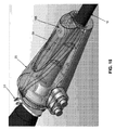
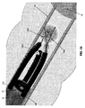
本発明に従って、また、図1を参照すると、新規な装置5が図示されており、該新規な装置は、内視鏡10(例えば、関節動作式内視鏡)を使用する内視鏡的術を行う間、検査及び/又は治療のため、側壁組織をより一層良く呈示することができるように(最初に隠れ又は視界外にある領域の視覚化を含む)、体腔及び/又は身体空洞の側壁を操作することができると共に、内視鏡10の末端及び/又はその他の機器(例えば、図1に図示しない、把持器、カッター、又は切除器、焼灼器具、超音波プローブ等のような)の末端の先端及び/又は作用端部を安定化させることができる。
Novel Device In accordance with the present invention and with reference to FIG. 1, a novel device 5 is illustrated, which is an endoscope using an endoscope 10 (eg, an articulating endoscope). Body cavity and / or body so that sidewall tissue can be better presented for examination and / or treatment during mirror surgery (including visualization of areas initially hidden or out of sight) The side walls of the cavity can be manipulated and the distal end of the
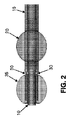
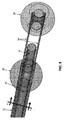
より特定的には、装置5は、全体として、内視鏡10の軸の外側の上を摺動し得るようにされたスリーブ15と、スリーブの末端付近にてスリーブ15に固定された基端側(すなわち「後側」バルーン20(「基端側」及び「後側」という語は、以下に互換可能に使用する)と、スリーブ1の基端にてスリーブ15に固定された基部25とを備えている。装置5は、以下に説明するように、スリーブ15に摺動可能に装着された一対のプッシュ管30と、プッシュ管30の末端に固定された末端側(すなわち、「前側」)バルーン35(「末端側」及び「前側」という語は、以下に互換可能に使用する)とを備え、プッシュ管30をスリーブ15に対して動かす外科医(又はその他の操作者又は使用者)が後側バルーン20と前側バルーン35との間の間隔を調節することのできるようにする(例えば、二つのプッシュ管をプッシュ管ハンドル37にて手で同時に動かすことにより。以下を参照)。図1及び図2−4を参照。装置5は、外科医(又はその他の操作者又は使用者)により後側バーン20及び前側バルーン35の一方又は双方を選択的に拡張/収縮させることを可能にするため、関係した拡張機構40(図1)も備えている。
More specifically, the device 5 generally comprises a
次に、図1−図6を参照すると、スリーブ15は、全体として、内視鏡の軸の外側の上を摺動し(例えば、内視鏡の末端の先端から後退させる)、内視鏡と密着嵌めする構造とされた細長い、薄い肉厚の管を備えており、スリーブは、装着する間(好ましくは、内視鏡は(「ドライ」状態にある)、内視鏡の上を容易に戻るが、内視鏡の外面に対して十分な残留摩擦を有するようにし(外科医又はその他の操作者又は使用者が把持したとき)、スリーブは、所要位置に留まり、使用する間(例えば、患者の結腸内にて)、内視鏡にトルク力を加え(すなわち、回転可能に方向変更し)押し/引っ張ることを許与する。本発明の1つの好ましい形態において、スリーブ15は、内視鏡10の回りにてある程度、周方向に動くことができる(また、外科医又はその他の操作者又は使用者の手でしっかりと把持したとき、内視鏡の軸と共に回転することができる)。しかし、スリーブ15は、内視鏡10に対して軸方向に名目的にのみ動くことができる。スリーブ15は、その末端が内視鏡10の末端と実質的に整合されたとき、スリーブ15は、(基部25と共に)内視鏡の軸を実質的に覆うような寸法とされる。何れの場合でも、スリーブ15は、該スリーブが内視鏡10に装着され、また、内視鏡10が患者の体内に挿入されたとき、スリーブ15が患者の身体外に延伸するような寸法とされている。本発明の1つの好ましい形態において、共に使用することを意図する特定の内視鏡に従った装置5が提供され、該装置5は、基部25が内視鏡のハンドルと係合したとき、スリーブ15の末端が内視鏡の末端にて適正に配置される、すなわち、内視鏡の末端と実質的に整合され、又は内視鏡の末端の僅かに基端側となるような寸法とされている。
Referring now to FIGS. 1-6, the
所望であれば、スリーブ15の末端には、内視鏡10の末端表面と確実に係合し、これにより、スリーブ15の末端が内視鏡10の末端表面を超えて基端方向に動くのを防止するよう半径方向内方に延伸するストッパ(図示せず)を設けることができる。かかる半径方向内方に延伸するストッパは、また、結腸内にある間、内視鏡がトルク作用(すなわち、回転可能に方向変更する)とき、スリーブ15が内視鏡10に対して「トルクスリップ」するのを防止及び/又は結腸内にある間、内視鏡を前方に押すとき、スリーブ15が内視鏡10に対して「スラストスリップ」するのを防止するのを助けることもできる。
If desired, the distal end of the
スリーブ15は、組織に対して非創傷的であるように円滑な外面を有することが好ましく、また、高度に可撓性の材料にて出来ており、スリーブは、使用中、内視鏡が曲がるのを阻止しないようにすることが好ましい。本発明の1つの好ましい形態において、スリーブ15は、ポリウレタン、ポリエチレン、ポリ(塩化ビニル)(PVC)、ポリテトラフルオロエチレン(PTFE)等から成っており、また、透明(又は少なくとも半透明)であり、内視鏡10の距離マークをスリーブ15を通して視覚化することを許容することが好ましい。また、本発明の1つの好ましい形態において、スリーブ15は、名目的な曲げ強度を有し、外科医(又はその他の操作者又は使用者)がスリーブ15を通して内視鏡10を把持し、例えば、内視鏡にトルク力を加えることができるようにすることが好ましい。所望であれば、スリーブ15は、その内面及び/又はその外面の一部又は全部に潤滑性被覆(例えば、過フルオロポリエーテル合成油のような液体、紛体等)を含み、スリーブを内視鏡の上に配設しかつ/又は装置が体腔及び/又は身体空洞を通って動くのを容易にすることができる。これと代替的に、スリーブ15は、例えば、ポリテトラフルオロエチレン(PTFE)等のようなそれ自体、潤滑性である材料にて形成してもよい。スリーブ15の内面は、スリーブが使用中、内視鏡に対して回転するのを防止する造作部(例えば、リブ)を含むことができることを理解すべきである。
The
所望であれば、スリーブ15と内視鏡10との間にて真空を「吸引」し、これにより、スリーブ15を内視鏡10に固定しかつスリーブ15の外輪郭を最小にすることができる。限定的ではなく、単に一例として、スリーブ15の基端(すなわち、基部15)にて真空を導入してもよく、又はスリーブ15の中間の箇所にて真空を導入してもよい。限定的ではなく、更なる例として、スリーブ15と内視鏡10との間の空間、例えば、スリーブ15の基端(すなわち、基部25)又はスリーブ15の中間にて流体(例えば、空気又は液体潤滑剤)を導入することにより、内視鏡15からのスリーブ15の除去(例えば、術の終了時)を容易にすることができることも理解すべきである。
If desired, a vacuum can be “sucked” between the
更に、図1−6を参照すると、後側バルーン20は、スリーブの末端に近いが、該末端から離間して、内視鏡の関節動作式継手の基端側にてスリーブ15に固定されている。後側バルーン20は、スリーブ15の回りにて同心状に、したがって、スリーブ15内に配設された内視鏡10の回りにて同心状に配設されている。このため、後側バルーンは、全体として、円環状の形状をしている。後側バルーン20は、基端の拡張/収縮管45によって選択的に拡張/収縮させることができ、該管45は、その末端がバルーン20の内部と流体的に連通しており、また、その基端は、基部25に装着された接続具46と流体的に連通している。接続具46は、上述した関係する拡張機構40と接続可能な構造とされている。接続具46は、ルア作動式弁であり、後側バルーン20内の圧力を失うことなく、拡張機構40を接続具46から切り離すことを許容することが好ましい。拡張/収縮管45は、スリーブ15の外面に固定することができ、又は、より好ましくは、拡張/収縮管45は、スリーブ15内に形成された管腔47内に保持することができるものとする。
1-6, the
好ましくは、後側バルーン20は、スリーブ15の末端から後方に短い距離にて、すなわち、ステア可能な内視鏡がスリーブ15内に配設されたとき、ステア可能な内視鏡10の関節動作式接続部分が後側バルーン20の末端側に配設されるように、ステア可能な内視鏡10の関節動作式接続部分の長さとほぼ等しい距離だけ、配設されている。この構造は、以下に更に詳細に説明するように、内視鏡の隣接する非関節動作式部分を身体部位に対して安定化させ得るように、後側バルーン20が身体部位内にて拡張したときでさえ、ステア可能な内視鏡の可撓性部分が関節動作することを許容する。このため、拡張したとき、後側バルーン20は、内視鏡10を体腔又は身体空洞内にて安定的な位置に維持する確実な基台を提供し、内視鏡10は、体腔又は身体空洞内にて中心決めされている。その結果、内視鏡10は、身体部位の視覚化を改良することができる。更に、内視鏡10が拡張した後側バルーン20により体腔又は身体空洞内にて確実に維持されている限り、内視鏡10の内管腔(「作用チャネル」又は「複数の作用チャネル」と称される場合もある)を通して前進させた機器には、体腔又は身体空洞内にてこれらの機器を支持するための確実な基台が設けられることになろう。
Preferably, the
後側バルーン20が適正に拡張したとき、後側バルーンは、非創傷的にその内部に装置5が配設された体腔の側壁と係合しかつ該側壁と密封関係を形成することができる。
When the
本発明の1つの好ましい形態において、後側バルーン20はポリウレタンにて形成される。
In one preferred form of the invention, the
基部25は、スリーブ15の基端に固定される。基部25は、内視鏡10と係合しかつ組立体(すなわち、装置5)の全体を内視鏡10に対して固定するのを助ける。基部25は、実質的に剛性な又は半剛性の構造体を備えることが好ましく、該構造体は、外科医(又はその他の操作者又は使用者)が把持し、かつ基端方向に引っ張り、これにより、外科医(又はその他の操作者又は使用者)がスリーブ15を内視鏡10の末端の上にて引っ張り、次に、内視鏡10の長さに沿って基端方向に戻して、これにより、スリーブ15を内視鏡の軸の外面に対して固着することを許容する。本発明の1つの好ましい形態において、基部25は、該基部25が内視鏡ハンドルに対して着座する迄、内視鏡に沿って基端方向に引っ張られ、これにより基部25の更なる基端方向への動きを防止する(従って、これにより、スリーブ15の更なる基端方向への動きを防止する)。本発明の1つの好ましい実施の形態において、基部25は、内視鏡10と密封係合する。
The
プッシュ管30は、スリーブ15に摺動可能に装着され、これにより、プッシュ管の末端は、スリーブ15に対して延伸させかつ/又は退却させ(例えば、プッシュ管をプッシュ管ハンドル37を介して前進させかつ/又は引き出すことにより。以下を参照。)、従って、スリーブ15内に配設された内視鏡10の末端に対して延伸させかつ/又は退却させることができる。好ましくは、プッシュ管30は、支持管50内に摺動可能に配設され、該支持管は、スリーブ15の外面に固定され、又は、より好ましくは、スリーブ15に形成された管腔52内に保持されるものとする。支持管50は、低摩擦材料(例えば、「PTFE」としても知られたポリテトラフルオロエチレン)にて形成し、プッシュ管30の支持管50に対する動きに対する抵抗を最小にする(したがって、プッシュ管30のスリーブ15に対する動きの抵抗を最小にする)ことが好ましい。この点に関して、プッシュ管30の支持管50に対する動きに対する抵抗を最小にすることは、プッシュ管30を使用して前側バルーン25を操作するとき、使用者に対する触覚的フィードバックを向上させることになることを理解すべきである。本発明の1つの形態において、支持管50は可撓性である(術を行う間、内視鏡10、特に、ステア可能な内視鏡10の関節動作部が必要に応じて撓むことを許容するように)。しかし、支持管50は、多少の縦方向強さを提供する。このため、支持管50がスリーブ15に形成された管腔52内に装着されたとき、スリーブ15と支持管50との組立体は、可撓性であるが、ある程度の縦方向強さを有する(一方、スリーブ15は単独では、可撓性であるが、実質的に縦方向強さはない)。プッシュ管50がスリーブ15に形成された管腔52内に保持される場合、また、支持管50がプッシュ管30及び管腔52内に配設されない場合、管腔52は、潤滑して、プッシュ管30と管腔52との間の摩擦を最小にすることが好ましい。
The
プッシュ管50の基端は、プッシュ管ハンドル37と接続されている。この構造の結果、プッシュ管ハンドル37を末端方向に押すと、プッシュ管30の末端は、スリーブ15に対して末端方向に動き(同一の程度)(これにより、前側バルーン35を後側バルーン20に対して基端方向に動かす)、また、プッシュ管ハンドル37を基端方向に引っ張ることにより、プッシュ管30の末端は、スリーブ15に対して基端方向に退却し(同一の程度)(これにより、前側バルーン35を後側バルーン20に対して基端方向に動かす)。プッシュ管30を同一の程度、末端方向に又は基端方向に動かすことにより、プッシュ管の末端は、互いに平行に維持されることに注目すべきである。プッシュ管30を基部25に対して選択した位置(したがって、スリーブ15に対して選択した配設位置)に保持するため、クランプ53(図12及び図15)が基部25に設けられる。
The proximal end of the
プッシュ管30は、例えば、Isoplast(登録商標)(オハイオ州、ウィックリフェのルブリゾールコーポレレーション(The Lubrizol Corporation)から入手可能)のような熱可塑性ポリエチレン樹脂、ポリエチレン、ポリプロピレン、ナイロン等のような、優れた縦方向強さを提供する比較的可撓性の材料にて形成することが好ましい。プッシュ管30は、単一の材料又は複数の材料から成るものとすることができ、また、プッシュ管30の剛性は、その長さに沿って変化するようにすることができることを理解すべきである。限定的ではなく、単に一例として、プッシュ管30の最末端部分は、プッシュ管のその他の部分と同一であるが、低弾性率の材料にて形成し、プッシュ管の他の部分よりも可撓性であるようにし、又は、プッシュ管30の最末端部分は、異なる、より弾性的な可撓性の材料から成るものとすることができる。限定的ではなく、単に一例として、プッシュ管30の最末端部分は、ニチノールから成るものとすることができる。限定的ではなく、更なる例として、プッシュ管30の最末端部分は、ポリテトラフルオロエチレン(PTFE)の外側ジャケットにて被覆したステンレススチールコイルから成るものとし、最末端のジャケット/より基端側の管は、共に、前側バルーン35を拡張/収縮させる密封した管腔を提供することができる。プッシュ管の他の部分よりも可撓性である末端を有するプッシュ管30を形成することにより、プッシュ管30及び前側バルーン35は、共に、以下に更に説明するように、装置5及び内視鏡10に対するリード(柔軟な非創傷性の先端を有する)として共に機能することができる。
Push
本発明の1つの好ましい形態において、プッシュ管30は、非偏奇状態にあるとき、すなわち、プッシュ管30に力が加わらないとき、平行な配設状態を維持する構造とされている。このことは、前側バルーン35が拡張又は収縮状態であるかどうかを問わず、そうである。
In one preferred embodiment of the present invention, the
プッシュ管30の最末端部分は、所望であれば、内方に又は外方に曲がるような構造とすることができる。かかる構造の場合、プッシュ管30の末端の先端が静止状態に維持され(例えば、以下に説明するように、拡張した前側バルーンにより)、また、末端方向に向けた十分な力がプッシュ管30に加えられたとき、プッシュ管30の中間部分(すなわち、拡張した前側バルーン35とスリーブ15との間の部分)は、外方に曲がり又は屈曲し、これにより、その内部に装置5が配設された体腔の側壁を外方に押して、これにより、後側バルーン20と前側バルーン35との間の空間内にて体腔及び/又は身体空洞に対して「テント張り」効果を提供する。この「テント張り」効果は、その内部に装置5が配設された体腔及び/又は身体空洞の側壁を外方に押すことにより、内視鏡の末端側にて視覚性及び/又は組織の安定性を著しく向上させることができる。
The distal end portion of the
プッシュ管30を可撓性材料にて形成することにより、使用中、それらの位置を手動にて調節し(例えば、別個の器具を使用し、装置にトルク作用を加えること等により)プッシュ管が患者の身体部位の視覚化に干渉しかつ/又は前側バルーと後側バルーンとの間の空間内に挿入された診断又は治療器具と干渉するのを防止することが可能であることを理解すべきである。限定的ではなく、単に一例として、プッシュ管30が身体部位の標的領域への視覚的又は物理的アクセスを妨害しないような仕方にて装置5が身体部位内に配設されたならば、別個の器具又は機器を使用することにより、又はトルク作用動作により装置を回転させて、可撓性のプッシュ管30を経路外に動かすことにより、可撓性のプッシュ管30は、経路外に動かすことができる。限定的ではなく、単に更なる例として、プッシュ管30を円形でかつ可撓性であり、また、内視鏡10の丸い円周よりも著しく小さい直径の構造とすることにより、丸型の内視鏡の動きは、関節動作させたとき、プッシュ管を経路外に押して、関心のある組織への妨害されない視覚的経路を提供することができる。
By forming the
所望であれば、プッシュ管30は、距離マーカ(図面に図示せず)、例えば、カラーインジケータ又は放射線不透過性インジケータを含むインジケータにて標識して、内視鏡10を介して又は放射線医学的案内(例えば、X線蛍光透視法)により外科箇所を観察する外科医(又はその他の操作者又は使用者)が体腔及び/又は身体空洞の側壁に対して長手方向にかつ/又は周方向に外科箇所におけるプッシュ管30の相対的な配設位置を確認することができることも理解すべきである。
If desired, the
以下に更に詳細に説明するように、ブッシュ管30は、中空であり、それらの末端は、前側バルーン30の内部と流体的に連通しており(図1−5、図7及び図8)、また、それらの内管腔は、基部25に装着した接続具56と流体的に連通している。接続具56は、上述した関係する拡張機構40と接続し、前側バルーン35を空気又はその他の流体(液体を含む)にて選択的に拡張し/収縮することができるようにする。接続具56は、ルア作動式弁であり、前側バルーン35内の圧力を失うことなく、拡張機構40を接続具56から切り離すことを許容する。
As will be described in more detail below, the
より特定的には、本発明の1つの好ましい形態において、また、図8Aを参照すると、プッシュ管ハンドル37は、中空の内部57を有している。プッシュ管30は、プッシュ管ハンドル37に装着されて、プッシュ管30がプッシュ管ハンドル37と共に動き、また、プッシュ管30の中空の内部がブッシュ管ハンドル37の中空の内部と流体的に連通するようにする。プッシュ管ハンドル37は、プッシュ管ハンドル37の中空の内部57と流体的に連通した接続具58も備えている。可撓性の管59は、接続具58を基部25の内部チャンバ(図示せず)と接続し、この基部25の内部チャンバは、上述した接続具56と流体的に連通している。この構造の結果、プッシュ管ハンドル37を末端方向に動かしたとき、前側バルーン35は、基端方向に動き、また、プッシュ管ハンドル37を基端方向に動かしたとき、前側バルーン35は、基端方向に動く。更に、基部25の接続具56に正の流体圧力を加えたとき、正の流体圧力が前側バルーン35の内部に加えられ、これにより、前側バルーンを拡張させ、また、基部25の接続具56に負の流体圧力を加えたとき、前側バルーン35の内部に負の流体圧力が加えられ、これにより、前側バルーン35を収縮させる。
More specifically, in one preferred form of the invention, and with reference to FIG. 8A, the push tube handle 37 has a
二つのプッシュ管を提供することは、多数の利点をもたらすことを認識すべきである。限定的ではなく、単に一例として、二つのプッシュ管を提供することは、以下に説明するように、前側バルーンが体腔内に末端方向に前進したとき、前側バルーン35に対して対称的な力を付与することになる。更に、二つのプッシュ管30を提供することは、プッシュ管を採用して内視鏡10の末端の基端側の領域内にて身体部位を真っ直ぐにするとき、隣接する身体部位に対して等しい外方への力を加え、これにより、以下に説明するように、身体部位の視覚化及び/又はアクセスを向上させることになる。更に、二つのプッシュ管を提供することは、前側バルーン35が内視鏡10の上にて中心決めされたままであり、これにより、前側バルーン35の内視鏡10からの結合解除及び前側バルーン35の内視鏡10の上での再結合を容易にすることを保証する。更に、二つのプッシュ管30を提供することは、前側バルーン35が内視鏡の先端に対して安定的であり、拡張したとき、前側バルーンの回転動作を最小にすることを保証することになる。更に、二つの中空のプッシュ管を提供することは、前側バルーン35を拡張し又は収縮するための冗長的な空気移送システムを提供することになる。
It should be appreciated that providing two push tubes provides a number of advantages. By way of example only, and not by way of limitation, providing two push tubes provides a symmetrical force with respect to the
前側バルーン35は、プッシュ管30の末端に固定されて、これにより、プッシュ管30をスリーブ15に対して動かすことにより、すなわち、ブッシュ管ハンドル37をスリーブ15に対して動かすことにより、後側バルーン20と前側バルーン35との間の間隔を調節することができる。更に、中空のプッシュ管30は、前側バルーン35の内部と接続具56との間に導管を提供し、これにより、前側バルーン35を接続具56を介して選択的に拡張/収縮することを可能にする。
The
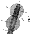
重要なことは、前側バルーン35は次のような構造とされている。すなわち、(i)該バルーンが収縮し(又は、部分的に収縮し)、また、スリーブ15に対して「退却した」位置(図2)にあるとき、前側バルーン35は、スリーブ15及び内視鏡10の軸を受け入れるのに十分な軸方向開口63(図7、図8及び図10)を提供し、これにより、前側バルーン35は、スリーブ15及び内視鏡10の上にて「結合」することができ、(ii)前側バルーン35がスリーブ15に対してその「延伸した」位置にあり、また、適正に拡張したとき(図4)、軸方向開口63は閉塞される(好ましくは、完全に閉塞される)ような構造とされている。これと同時に、適正に拡張させたとき、前側バルーンは、その内部に装置5が配設された体腔及び/又は身体空洞の側壁と非創傷的に係合しかつ密封関係を形成する。このように、前側バルーン35が適正に拡張したとき、前側バルーンは、軸方向に開口63を閉塞しかつその内部に装置5が配設された体腔及び/又は身体空洞の側壁との密封関係を形成することにより、前側バルーン35の末端側にて体腔及び/身体空洞を効果的に密封することができる。このようにして、プッシュ管30が末端方向に前進して、前側バルーン35を後側バルーン20から分離させるとき、また、前側バルーン35及び後側バルーン20を適正に拡張させたとき、二つのバルーンは、その間にて密封領域(以下にて「治療領域」と称することもある)を形成する。
Importantly, the
前側バルーン35がその収縮した状態からその拡張した状態に形態を変化させるとき、前側バルーン35は、半径方向内方に膨張し(軸方向開口63を閉塞するように)、また、半径方向内方に膨張し(周囲の組織と係合し得るように)ことが理解されよう。
When the
このように、前側バルーン35は、収縮したとき、「円環状」の形状となり(該バルーンが内視鏡の末端の上に着座するのを許容し得るように)、また、拡張したとき、実質的に「中実」な形状となる(該バルーンが体腔又は身体空洞を閉塞することを許容し得るように)ことが理解されよう。
Thus, the
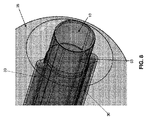
この目的のため、また、図9及び図10を参照すると、前側バルーン35は、基端側開口69と、末端側開口71とを有する本体67と、ローブ74を有する「キー形状の断面」を有する基端側延伸部73と、円形断面を有する末端側延伸部76とを備える、単一の構造体として製造することが好ましい。ローブ74は、プッシュ管30の構造と適合する構造にて基端側延伸部73上に配設され、(すなわち、装置5が互いに、直径方向に対向した二つのプッシュ管30を備える場合、基端側延伸部73は、互いに直径方向に対向した二つのローブを備える。また、装置5がスリーブ15の周縁45にて等しく外周方向に隔てた三つのプッシュ管30を備える場合、基端側延伸部73は、基端側延伸部73の周縁の回りにて等しく周方向に隔てた三つのローブ74を備えている。装置5が一つのプッシュ管30を備える場合、基端側延伸部73は、1つのローブ74を備える、等であり、本発明の目的のため、基端側延伸部73及びローブ74は、集合的に、「キー形状」の断面を有するものと称することできる)。組み立てる間、プッシュ管30は、基端側延伸部73のローブ74内に着座し、基端側延伸部73は、本体67の内部に裏返され(中空のプッシュ管30の内部は、本体67の内部と流体的に連通する)、また、次に、末端側延伸部76は、基端側延伸部73の内部に裏返され、これにより、貫通して延伸する軸方向開口63を有する前側バルーン35を提供し、プッシュ管30は、前側バルーン35に固定されかつ前側バルーン35の内部と連通する。重要なことは、軸方向開口63は、内視鏡10の末端を受け入れる寸法とされている。また、重要なことは、基端側延伸部73を本体67の内部に裏返され、次に、末端側延伸部76を基端側延伸部73の内部に裏返される、上述した過程によって前側バルーン35を形成することは、プッシュ管30の回りにてバルーン材料の多層を提供し、これにより、より堅牢なバーン構造を提供することになる。特に、プッシュ管30の回りにてバルーン材料の多層を提供することは、プッシュ管30の末端に対する緩衝効果を追加し、これにより、プッシュ管30に対する一層の非創傷的な末端の先端を提供し、更に、プッシュ管30の末端の先端が隣接する組織に損傷を与えないことを保証することになる。
For this purpose and with reference to FIGS. 9 and 10, the
本発明の1つの好ましい形態において、前側バルーン35は、ポリウレタンにて形成される。
In one preferred form of the invention, the
前側バルーン35がその収縮した状態にあるとき、前側バルーンの35の材料は、プッシュ管30の末端を実質的に取り囲み(プッシュ管30が前側バルーン35の内部と流体的に連通することを許容しつつ)、これにより、前側バルーン35を体腔を通して末端方向に前進させるための非創傷的な先端を提供することを理解すべきである。更に、プッシュ管30及び収縮した前側バルーン35は、共に、基本的に、以下に更に説明するように(図20)、装置5及び内視鏡10に対する柔軟な先端のリードとして機能することができる。
When the
所望であれば、後側バルーン20及び前側バルーン35の一方又は双方は、インジケータ(例えば、カラーインジケータ又は放射線不透過性インジケータ)にて標識し、内視鏡10又は放射線医学的案内(例えば、X線蛍光透視法)を介して外科箇所を観察する外科医(又はその他の操作者又は使用者)が外科箇所における一方又は双方のバルーンの配設状態を確認することができるようにする。
If desired, one or both of the
拡張機構40は、後側バルーン20及び/又は前側バルーン35を選択的に拡張させる手段を提供する。
The
本発明の1つの好ましい形態時において、また、図1及び図11を参照すると、拡張機構40は、本体145と、プランジャ150とを有する単一ライン注射器インサータ140を備えている。好ましくは、その行程の終了時にプランジャ150を自動的に戻すためのばね153が本体145に設けられるものとする。注射器インサータ140は、管155を介して接続具46、56の一方又はその他方に接続されている。このように、この構造の場合、単一ライン注射器インサータ140が後側バルーン20を拡張させるために使用される場合、注射器インサータ140は、管155を介して接続具46と接続され、単一ライン注射器インサータ140の出力は後側バルーン20に向けられる(すなわち、基端の拡張/収縮管45を介して)。これに対応して、単一ライン注射器インサータ一40を使用して前側バルーン35を拡張させるべきとき、注射器インサータ一140は、管155を介して接続具56と接続されて、単一ライン注射器インサータ140の出力は、前側バルーン35に向けられる(すなわち、可撓性管59及びプッシュ管30の中空の内部を介して)。
In one preferred form of the invention, and with reference to FIGS. 1 and 11, the
本発明の別の好ましい形態において、拡張機構40は、第一のポート57と、第二のポート58とを有する弾性的なバルブ156を備えている。一方向弁159(例えば、逆止弁)は、第一のポート157に配設されて、空気は外方向に流れるとき、第一のポート157を通ってのみ流れることができる。別の一方向弁159(例えば、逆止弁)は、第二のポート158に配設されて、空気は、内方に流れるとき、第二のポート158を通ってのみ流れることができる。弾性的なバルブ156が圧縮されると(例えば、手で)、弾性的なバルブ156の内部の空気は、第一のポート157から押し出される。弾性的なバルブ156がその後、解放されると、空気は、第二のポート158を通って弾性的なバルブ156内に吸引されて戻る。
In another preferred form of the invention, the
この構造の結果、弾性的なバルブ156を使用して後側バルーン20を拡張させるべきとき、第一のポート157は、管155を介して接続具46と接続され、弾性的なバルブ156の正圧力の出力は後側バルーン20向けられる。弾性的なバルブ156は、その後に使用して後側バルーン20を収縮させることができる、すなわち、第二のポート158を管155を介して、接続具46と接続し、弾性的なバルブ156の吸引力が後側バルーン20向けられるようにする。これに対応して、弾性的なバルブ156を使用して前側バルーン35を拡張させるべきとき、第一のポート157は、管155介して接続具56と接続され、弾性的なバルブ156の正圧力の出力は、前側バルーン35向けられる。弾性的なバルブ156は、その後、前側バルーン35を収縮させるため使用することができる、すなわち、第二のポート158を管155を介して接続具56と接続し、弾性的なバルブの吸引力が前側バルーン35に向けられるようにする。
As a result of this structure, when the
これと代替的に、また、図12及び図13を参照すると、注射器160を使用して後側バルーンバーン20及び/又は前側バルーン35を拡張させることができる。拡張機構160は、本体161と、プランジャ162とを備えている。好ましくは、その作動行程の終了時にプランジャ162を自動的に戻すためのばね(図示せず)が本体161に設けられるものとする。注射器160は、管163を介して接続具46、56と接続されている。この構造の場合、注射器160は、注射器160を前側バルーン35に又は後側バルーン20に接続する弁165と、バルーンと接続された拡張又は収縮を選択する弁170とを備えている。
Alternatively and with reference to FIGS. 12 and 13, a
このように、この構造の場合、注射器160を使用して、後側バルーン20を拡張させるべきとき、弁165(弁170を前側バルーン又は後側バルーンの何れかに接続する二位置弁)は、注射器160が接続具46を通して後側バルーン20に接続されるように設定し、弁170(一方向弁を1つの形態にて拡張させ、その他の形態にて収縮させるよう配置することを許容する二方向クロスオーバ弁)は、注射器160が拡張圧力を提供するように設定する。その後、後側バルーン20を収縮させるべきとき、弁170は、その収縮位置に設定する。
Thus, in this configuration, when the
これに対応して、注射器160を使用して前側バルーン35を拡張させるべきとき、弁160は、注射器160が接続具56を通して前側バルーン35と接続されるように設定し、弁170は、注射器160が拡張圧力を提供するように設定する。その後、前側バルーン35を収縮させるべきとき、弁170は、その収縮位置に設定する。
Correspondingly, when the
本発明の更に別の形態において、拡張機構40は、自動的な流体圧力(正又は負の何れか)の供給源、例えば、電気ポンプを備えることができる。
In yet another form of the invention, the
所望であれば、また、図14を参照すると、逃し弁175は、拡張/収縮管と接続することができ、該拡張/収縮管は、前側バルーン35と接続し、前側バルーン35内の圧力が所定のレベルを超えないことを保証する。同様に、更に、図14を参照すると、逃し弁180は、拡張/収縮管と接続することができ、該拡張/収縮管は、後側バルーン20と接続し、後側バルーン20内の圧力が所定のレベルを超えないことを保証することができる。
If desired, and referring also to FIG. 14, the relief valve 175 can be connected to an expansion / contraction tube that connects to the
これと代替的にかつ/又は追加的に、1つ以上の圧力計182(図1又は図13)を後側バルーン20と接続した流体管内に及び/又は前側バルーンと接続した流体管内に組み込み、これにより、外科医(又はその他の操作者又は使用者)に対して後側バルーン20及び前側バルーン35内の圧力に関する情報を提供し、過度の拡張を避けかつ/又は外科医(又はその他の操作者又は使用者)が術を行う間、バルーンの拡張状態を確認するのを助けるようにすることができる。
Alternatively and / or additionally, one or more pressure gauges 182 (FIG. 1 or FIG. 13) are incorporated into the fluid conduit connected to the
更に、前側バルーン35は、その「退却した」位置(図2)とその「延伸した位置」(図4)との間にて動き、プッシュ管30を基部25(従って、接続具56)と接続する可撓性の管59は、基部25の回りに集まり、外科医(又はその他の操作者又は使用者)の動作に干渉する可能性があることが理解されよう。従って、所望であれば、また、図15を参照すると、可撓性の管退却システム185を提供し(例えば、基部25内に)、前側バルーン35が延伸したときの可撓性の管59の弛みを取ることができる。
新規な装置の好ましい使用方法
装置5は、体腔及び身体空洞の側壁を操作し(例えば、落ち着かせ、真っ直ぐにし、膨張させかつ/又は平坦にする等)、内視鏡10を使用する内視鏡的術を行う間、検査及び/又は治療のため側壁の組織を一層良く呈示するため(最初、隠れ又は視界外の領域の視覚化を含む)、かつ/又は例えば、治療領域内に前進させた機器(例えば、把持器、カッター又は切除器、焼灼器具、超音波プローブ等)の末端の先端及び/又は作用端部を安定化させるために使用することができる。
Further, the
Preferred Use of the New Device The device 5 is an endoscope that manipulates the body cavity and the side walls of the body cavity (eg, calms, straightens, inflates and / or flattens, etc.) and uses the
より特定的には、使用中、スリーブ15を最初に内視鏡10(図1)に装着する。このことは、基部25を内視鏡10の末端の上にて基端方向に引っ張り、次に、スリーブ15の末端が内視鏡10の末端の先端と実質的に整合される迄、内視鏡10の長さに沿って基端方向に引っ張ることにより実現することができる。この時点にて、後側バルーン20は収縮し、前側バルーン35は収縮しており、前側バルーン35は、内視鏡10の末端の上にて結合されている。内視鏡10及び装置5は、患者の体内にユニットとして挿入する用意が整う。
More specifically, during use, the
次に、図16を参照すると、内視鏡10及び装置5は、患者の体腔及び/又は身体空洞内にユニットにして挿入される。限定ではなくする、単に一例として、内視鏡10及び装置5は、患者の胃腸管(GI)内にユニットとして挿入される。内視鏡10及び装置5は、患者の体内の所望の箇所まで体腔及び/身体空洞に沿って前進させる(図17及び図18)。
Referring now to FIG. 16, the
装置5を使用すべきとき(例えば、胃腸管の側壁を操作し、該箇所の視覚化を向上させかつ/又は該箇所へのアクセスを容易にし、かつ/又は該箇所に対して機器を安定化させるとき)、後側バルーン20は拡張させ、体腔及び/身体空洞内にて装置5(したがって、内視鏡10)を安定化させる。図19参照。このことは、上述した関係する拡張機構40を使用して行うことができる。
When the device 5 is to be used (for example, manipulating the side wall of the gastrointestinal tract to improve visualization of the location and / or facilitate access to the location and / or stabilize the device relative to the location) The
この点に関して、内視鏡の関節動作部分が後側バルーン20に対して末端側に位置する限り、内視鏡は、後側バルーン20が拡張した後でさえ、後側バルーン20の末端側にて関節動作し、身体部位の視覚化を容易にすることができることが理解されよう。重要なことは、後側バルーン20が胃腸管内にて内視鏡10を安定化させ、また、結腸を拡げかつ結腸を後側バルーンに隣接して直接、一定の直径まで増大させることができる限り、かかる視覚化は向上する点である。
In this regard, as long as the articulating portion of the endoscope is located distal to the
次に、プッシュ管30は、プッシュ管ハンドル37の上にて末端方向に押すことにより体腔及び/又は身体空洞内にて末端方向に前進させる(すなわち、前側バルーン35を後側バルーン20の更に前方にて動かすため)。このため、プッシュ管30、従って、前側バルーン35は、内視鏡10(該内視鏡は、拡張した後側バルーン20により胃腸管内の所要の位置にて安定化されている)に対して末端方向に動く。収縮した前側バルーン35は、前側バルーン35がかかる末端方向に動く間、プッシュ管30の末端を覆っており、これにより、前側バルーン35の非創傷的な前進を保証することになる点に注目すべきである。前側バルーン35の非創傷的な前進は、プッシュ管30の末端をより弾性的な材料にて形成することにより、向上させることができることを注目すべきである。
The
プッシュ管30が前側バルーン35を内視鏡10の末端側の所望の位置まで前進させたとき、前側バルーン35は拡張して(図20)前側バルーン35を身体部位に固定する。この場合にも、このことは、上述した関係する拡張機構40を使用して行うことができる。前側バルーン35が拡張したとき、拡張した前側バルーン35、拡張した後側バルーン20及びプッシュ管30は、すべて互いに相補的であり、体腔及び/又は身体空洞の側壁を安定化させ、真っ直ぐにし、膨張させかつ/又は平坦にして、内視鏡を使用する内視鏡的術を行う間、検査及び/又は治療のため、側壁組織を一層良く呈示し得るようにする(最初に隠れ又は視界外の領域の視覚化を含む)。この点に関して、拡張した前側バルーン35及び拡張した後側バルーン20は、共に体腔及び/又は身体空洞の側壁を膨張させかつ張力を加え、また、プッシュ管30は、前側バルーンが後側バルーンから末端方向に延伸したとき、二つの拡張したバルーンの間の身体部位を真っ直ぐにする傾向となることが理解されよう。この点に関して、後側バルーン20及び前側バルーン35の双方が拡張したならば、前側バルーン35は、体腔及び/身体空洞を渡って実質的に全直径を形成し(拡張した前側バルーンは、前側バルーンがその収縮した状態にあるとき、前側バルーンを通って延伸する軸方向開口63を閉塞するからである)、また、後側バルーン20は、スリーブ15及び内視鏡10と協働して、体腔及び/又は身体空洞を渡って実質的に全直径の別のバリアーを形成することが理解されよう。このように、拡張した前側バルーン35及び拡張した後側バルーン20は、共に、体腔及び/又は身体空洞に沿って実質的に閉塞した領域(すなわち、拡張した前側バルーン35及び後側バルーン20により確立された空気密のシールにより流体及び/又はその他の液体の通過を防止する孤立した治療領域)を形成することも理解されよう。体腔及び/又は身体空洞の側壁は、前側バルーン35及び後側バルーン20の拡張により張力が加えられ、これにより、内視鏡10を通して視認し得るように、体腔及び/又は身体空洞の側壁を一層良く呈示することになろう。
When the
拡張した前側バルーン35、拡張した後側バルーン20、及びプッシュ管30により実行される、体腔及び/身体空洞の側壁の膨張及び張力の付与は、前側バルーンが拡張し且つ体腔及び/又は身体空洞の側壁を把持するとき、前側バルーンを前進させることにより、さらに向上させることができ、これにより、体腔及び/又は身体空洞の側壁に張力を加えることができることが理解されよう。
The inflation and tensioning of the side walls of the body cavity and / or body cavity, performed by the expanded
重要なことは、拡張した前側バルーン35及び拡張した後側バルーン20が共に、体腔及び/又は身体空洞に沿って実質的に閉じた領域(すなわち、孤立した治療領域)を規定する限り、この領域は、次に、流体(例えば、空気、CO2等)にて拡張させ、体腔及び/又は身体空洞の側壁に更に張力を加え、これにより、内視鏡10を通して視認するため体腔及び身体空洞の側壁を一層良く呈示し、且つ側壁を安定化して、より正確な治療的介入を容易にすることができる。
Importantly, as long as the expanded
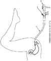
所望であれば、拡張した状態を維持しつつ(したがって、体腔及び/又は身体空洞の側壁にて把持力を維持しつつ)、前側バルーン35は、後側バルーン20に向けて退却させ(例えば、プッシュ管ハンドル37を基端方向に引っ張ることにより)、視認可能な粘膜を動かし、視認化及びアクセスを更に向上させ(例えば、図22参照)、例えば、内視鏡及び内視鏡器具に対する従来の角度にて体腔及び身体空洞の側壁に特定の標的領域を位置決めすることができる。
If desired, the
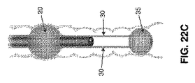
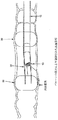
これと代替的に、所望であれば、後側バルーン35が拡張したならば、プッシュ管30をその全行程の一部分−一部分だけを末端方向に前進させ、次に、前側バルーン35を拡張して、体腔及び/又は身体空洞の側壁を把持するようにし、次に、プッシュ管30を末端方向に更に前進させることができる。この動作によって、可撓性のプッシュ管30は、外方に曲がり(図22A−22Dを参照)、体腔及び/又は身体空洞の側壁と接触し、且つ体腔及び/又は身体空洞の側壁を例えば、「テント張り」の仕方にて外方に押し、これにより、内視鏡10による体腔及び/又は身体空洞の側壁の視覚化をさらに向上させることになろう。
Alternatively, if desired, if the
所望であれば、機器190(図23)を内視鏡10の作用チャネルを通して前進させ、病理学的状態を生検しかつ/又は治療する(例えば、病理学的身体部位を切り取る)ことができる。かかる機器は、後側バルーン20を介して身体部位に対して効果的に安定化させた内視鏡の末端を通って延伸し、機器190の作用端部が身体部位に対して高度に安定化されることが理解されよう。このことは、内視鏡の安定化されていない端部から機器を前進させる先行技術の方法に勝る顕著な利点である。好ましくは、機器190は、完全な動作範囲を有する関節動作式機器を含み、これにより、標的の身体部位に一層良くアクセスすることができるようにする。
If desired, instrument 190 (FIG. 23) can be advanced through the working channel of
更に、出血のため、組織箇所が不鮮明になるならば、又は出血が生じ、外科医が出血源を識別することができない場合、孤立した治療領域は、その内部に治療領域が位置する身体部位を迅速に洗滌し(例えば、食塩水のような液体にて)、その後、洗浄液体を迅速に除去することを許容する(図24−図26参照)。 Further, if the tissue location becomes blurred due to bleeding, or if bleeding occurs and the surgeon cannot identify the source of the bleeding, the isolated treatment area will quickly locate the body part within which the treatment area is located. (E.g., with a liquid such as saline) and then allow the cleaning liquid to be quickly removed (see FIGS. 24-26).
また、所望であれば、前側バルーン35は、出血箇所まで極めて正確に案内することができ、その後、前側バルーン35を使用して(例えば、拡張して)出血箇所に居所的な圧力を付与し、出血の管理を向上させることができる(図27参照)。このことは、内視鏡10により提供される視覚化の下にて行うことができる。
Also, if desired, the
身体部位内にて内視鏡の位置を装置5による干渉が最小の状態にて変更することが望まれる場合、前側バルーン35は、その円環状の形態(すなわち、部分的に収縮した状態)に「退却させ」、前側バルーンを基端方向に退却させ、且つ内視鏡10の末端上にて再結合させ、後側バルーン20を収縮させ、次に、内視鏡10(装置10が担持された)を身体部位内にて再位置決めする。前側バルーン35を内視鏡10の末端にて再結合させようとする場合、前側バルーン35は、該前側バルーン35が内視鏡の末端上にて再結合される迄、部分的にのみ収縮させることが好ましく、それは、前側バルーン35の部分的拡張は、前側バルーンは十分な「本体」を維持し、再結合過程を容易にするからである。その後、前側バルーン35は、所望であれば、完全に収縮させ、例えば、内視鏡10の末端を確実に把持するようにすることができる。
When it is desired to change the position of the endoscope within the body part with minimal interference by the device 5, the
これと代替的に、所望であれば、前側バルーン35は、引きずり出し動作ブレーキとして使用し、内視鏡の後退動作を制御することができる。より特定的には、本発明のこの形態において、内視鏡10及び装置5は、最初に、ユニットとして、内視鏡の先端が適正な位置となる迄、体腔及び/又は身体空洞内に前進させる。次に、後側バルーン20を拡張させ、プッシュ管30を末端方向に前進させ、次に、前側バルーン35を拡張させる(図28)。次に、視覚化、また、選択的に、治療的処置をその位置にて行うことができる。装置を後退するように動かす場合、後側バルーン20を収縮させ、前側バルーン35を部分的に収縮させ、次に、内視鏡を基端方向に引き出し、半拡張した前側バルーン35を体腔及び/又は身体空洞に沿って引きずり出し(図29)、内視鏡が基端方向に引っ張られるとき、前側バルーン35がブレーキのように作用するようにし、これにより、内視鏡のより制御された後退動作を可能にしかつ身体部位を一層良く視覚化する。ある時点にて、望まれるならば、図30に示すように、2つのバルーンの間に確立された「孤立した治療領域」内に流体を導入し又は導入せずに、後側バルーン20及び前側バルーン35を再拡張させ、該身体部位を安定化させ、真っ直ぐにし、膨張させかつ/又は平坦化することができる。
Alternatively, if desired, the
内視鏡(したがって、装置5)を単独にて又は上述したブレーキ作用と組み合わせて、前側バルーン35から引き抜くとき、後側バルーン20をブレーキとして使用することも可能である。
It is also possible to use the
この術の終了時、内視鏡10及び装置5は、身体部位から引き抜く。好ましくは、このことは、前側バルーン35を収縮させ(又は部分的に収縮させ)、プッシュ管30を退却させ、前側バルーン35が内視鏡10末端上に「再結合」されるようにし、前側バルーン35を完全に収縮させ、該バルーンが内視鏡の末端を把持し、後側バルーン20(該バルーンがまだ、収縮していない場合)を収縮させ、次に、内視鏡10及び装置5を単一のユニットとして身体部位から引き抜くことにより行われるものとする。
At the end of this operation, the
装置5は、上述したもの以外の各種の方法にて有益に使用することもできることを理解すべきである。限定的ではなく、単に一例として、内視鏡10(及び装置5)を結腸内にて前進させるべきとき、最初に、前側バルーン35を内視鏡の視覚的案内の下にて末端方向に突き出し、前側バルーン35が内視鏡の末端をリードするようにすることが望ましい。その結果、前側バルーン35が収縮した(又は部分的に収縮した)状態にて内視鏡を末端方向に前進させたとき、内視鏡が結腸を通って前進するとき、前側バルーン及び可撓性のプッシュ管30は、内視鏡に対する非創傷的リード(案内構造体)として機能することができる。重要なことは、プッシュ管30の末端が極めて可撓性であることが好ましい限り、前進する前側バルーン35が結腸壁と遭遇するとき(例えば、結腸の曲がり部にて)、可撓性のプッシュ管は、偏向して、前側バルーンは、結腸の経路を追跡し、これにより、内視鏡を結腸に沿って非創傷的に前進させることを助けることである。また、装置5は、現在、実行することが困難な管腔の表面を更に検査することを容易にするため、その他の方法にて有益に使用することが可能であることも理解すべきである。かかる例は、流体を満たした拡張した前側バルーンにより容易となるであろう管腔の内視鏡的超音波検査、及び超音波プローブ検査である。
追加的な構造体
所望であれば、装置5は、次のような構造とすることができる。すなわち、プッシュ管30を互いに独立的に、また、互いに一緒に前進させ又は退却させることができる−プッシュ管30のかかる独立的な前進又は退却は、体腔及び/又は身体空洞を通して部分的に又は完全に収縮した前側バルーン35をステアすることを助け、これにより、体腔及び/又は身体空洞を通して内視鏡の前進又は退却を容易にし、かつ/又はプッシュ管30のかかる独立的な前進又は退却は、拡張した前側バルーン35により身体部位に「方向変更力」を加えることを容易にし、これにより、視覚化及び/又は治療のため、身体部位を一層良く呈示することができるような構造とする。
It should be understood that the device 5 can be beneficially used in various ways other than those described above. By way of example only and not limitation, when the endoscope 10 (and the device 5) is to be advanced in the colon, the
Additional Structures If desired, the device 5 can have the following structure. That is, the
限定的ではなく、単に一例として、本発明のこの形態において、また、図30Aを参照すると、プッシュ管30の各々は、プッシュ管ハンドル37に互いに独立的に摺動可能に装着され、プッシュ管30がプッシュ管ハンドル37及び互いに独立的に動くことができる。ストッパ191は、ブッシュ管ハンドル37に対するプッシュ管30の末端方向への動きを制限し、このため、プッシュ管は、完全にプッシュ管ハンドル37から外に動くことはできない。この構造の結果、前側バルーン35を末端方向に動かすべきとき、プッシュ管30は、一緒に又は互いに独立的に末端方向に動く。この術の任意の時点にて、プッシュ管30は、互いに独立的に動かし、例えば、前側バルーン35が拡張されかつ身体部位と係合するようなとき、前側バルーンを「方向変更」させ、これにより、身体部位に「方向変更力」を加え、又は、前側バルーン35が部分的に拡張させかつ前進する組立体に対する非創傷的先端として使用される場合、これにより、組立体を身体部位を通して「ステア」するのを助けることができる。プッシュロッド30が互いに独立的に、長手方向に動くことのできる程度を制限する制限機構を提供し、前側バルーン35の過度の方向変更、及び/又はプッシュロッドのクロスオーバー及び/又はプッシュロッドの絡まり及び/又はプッシュロッドの整合外れ等を防止することが望ましいことに注目すべきである。また、プッシュ管30を上述したクランプ53(図12及び図15)内に装着することにより、プッシュ管30は、特定の配設位置に保持することができることも注目すべきである。
By way of example only, and not by way of limitation, in this form of the invention and with reference to FIG. 30A, each of the
また、内視鏡10の外側にて機器(又は中空の機器の案内管)を支持し得るようにスリーブ15の構造を改変することも可能であることも理解すべきである。より特定的には、再度、図5及び図6を参照すると、図5及び図6に示した構造において、スリーブ15は、後側バルーン20を拡張/収縮させる拡張/収縮管45を受け入れる管腔47と、前側バルーン35を操作しかつ拡張/収縮させるプッシュ管30を受け入れる支持管50を受け入れる一対の管腔52とを備えていることが理解できる。しかし、所望であれば、スリーブ15は、内視鏡10の外側にて、機器(又は、中空の機器の案内管)を支持する追加的な管腔を含むことができる。
It should also be understood that the structure of the
より特定的には、また、図31を参照すると、機器190を摺動可能に受け入れる複数の管腔195を含むスリーブ15の別の形態の端面図が示されている。拡張したとき、後側バルーン20は、体腔及び/又は身体空洞内に内視鏡10及びスリーブ15を維持する確実な台部を提供し、内視鏡10及びスリーブ15は、体腔及び/又は身体空洞内にて中心決めされている。その結果、スリーブ15の管腔195の末端は、体腔及び/身体空洞内にて確実に維持され、スリーブ15の管腔196を通して前進させた機器に対する確実な支持部を提供する。
More specifically, and referring also to FIG. 31, an end view of another form of
管腔195の基端は、基部25までかつ該基部を通って延伸し、この場合、機器は、基部25にて管腔195内に挿入することができ、又は管腔195の基端は、基部25の基端側にて終わり(しかし、未だ患者の身体外にある)、この場合、機器は、スリーブ15の中間にて管腔195内に挿入することができる。限定的ではなく、単に一例として、内視鏡10の長さが180cmで、機器190の長さが60cmである場合、機器190をバルーン20、35に近い箇所にて(基部25ではなくて)管腔195内に挿入することが有益である。図31において、拡張/収縮管45を受け入れる管腔45、及び後側バルーン20を拡張/収縮させる拡張管/収縮管45は見ることができないが、それは、この図面は、末端方向を向いており、拡張/収縮管45がスリーブ15の上にて終わる箇所の末端の位置にて描いたものであるからである。
The proximal end of the
図32−図35には、管腔195から外に延伸する各種の機器190が図示されている。機器190は、例えば、図32−35の把持器190A、図32−33の焼灼装置190B、図34及び図35の鋏190C、及び図32−35の吸引装置190Dのような関節動作式機器を備えることが好ましいことに注目すべきである。
32-35 illustrate
スリーブ15が内視鏡104を受け入れるその中央通路と、拡張/収縮管45を受け入れる管腔47と、プッシュ管30を受け入れる支持管50を受け入れる管腔52と、及び/又は機器190を摺動可能に受け入れる管腔195とを備える場合、スリーブ15は、押し出し成形法にて形成されることが好ましいことを理解すべきである。
The
本発明の1つの好ましい形態において、拡張/収縮管45を受け入れる管腔47、プッシュ管30を受け入れる支持管50を受け入れる管腔52、及び/又は機器190を摺動可能に受け入れる管腔195は、一定の形態(すなわち、一定の直径)を有し、このためスリーブ15は、一定の外輪郭を有している。
In one preferred form of the invention, lumen 47 for receiving expansion /
本発明の別の好ましい形態において、拡張/収縮管45を受け入れる管腔47、プッシュ管30を受け入れる支持管50を受け入れる管腔52、及び/又は機器190を摺動可能に受け入れる管腔195は、膨張可能な形態を有することができる(すなわち、これらは、空のとき、最小の外輪郭を有し、充填されたとき、必要に応じて直径方向に膨張することができる)、このため、スリーブ15の全体的な外輪郭は最小となる。
In another preferred form of the invention, lumen 47 for receiving expansion /
スリーブ15が機器190を摺動可能に受け入れる複数の管腔195を備える場合、管腔195の末端に対してより大きい構造的一体性を提供し、管腔195内に受け入れた機器190に対して改良された支持状態を提供するようにすることが望ましいことも理解すべきである。この目的のため、支持リングをスリーブ15の末端に提供し、該支持リングは、プッシュ管30が通るための開口と、機器190が通るための開口とを提供するようにすることができる。機器190を通すためのかかる支持リングの開口は、機器と密着嵌めし、スリーブ15の末端にて優れた機器の支持状態を提供することに注目すべきである。
Where the
これと代替的に及び/又は追加的に、管腔195は、それ自体が機器を収容する中空の機器の案内管を収容することができる。かかる中空の機器の案内管は、管腔195の末端に対してより大きい構造的一体性を提供し、管腔195内に受け入れた機器190に対する改良された支持状態を提供することができる。また、かかる中空の機器の案内管は、一定の幾何学的形態、又は曲げ可能な又は関節動作式の幾何学的形態を提供することができる。例えば、管腔195から外に延伸しかつ機器190を受け入れる中空の機器の案内管200を示す、図36を参照。中空の機器の案内管200は、互いに独立的に可動(かつスリーブ15に対して独立的に可動)であることに注目すべきである。また、機器190は、中空の機器の案内管200と密着嵌めし、スリーブ15の末端にて優れた機器の支持状態を提供することにも注目すべきである。
Alternatively and / or additionally, the
所望であれば、二つのプッシュ管30に代えて単一のプッシュ管30を使用し又は例えば、三つのプッシュ管30のような、二つ以上のプッシュ管30を使用することができることも理解すべきである。複数のプッシュ管30が提供される場合、プッシュ管を互いに等しく周方向に離間させることが全体として、望ましく、また、例えば、二つのプッシュ管30が提供される場合、二つのプッシュ管30は、180°離間させることが全体として望ましく、三つのプッシュ管30が提供される場合、プッシュ管は、120°離間させること等が全体として望ましいことも理解されよう。
適用例
このように、本発明は、体腔及び/又は身体空洞の側壁を操作し、例えば、管腔の内面の曲がり部を真っ直ぐにし、「しごき加工をし」、且つ体腔及び身体空洞の実質的に静的又は安定的な側壁を形成するため、内視鏡的術を行う間、検査及び/又は治療のため、側壁の組織をより良く呈示し(最初は隠れ又は視界外の領域の視覚化を含む)かつより正確な視覚的検査(最初は隠れ又は視界外の領域の視覚化を含む)かつ/又は治療的介入を可能にする新規な装置を提供しかつ使用するステップを備えることが理解されよう。限定的ではなく、単に一例として、該新規な装置は、腸の側壁の曲がり部及び/又は折り曲げ部を安定化し、真っ直ぐにし、膨張させ、かつ/又は平坦化して、内視鏡的術を実施する間、検査及び/又は治療のため、側壁の組織をより良く呈示する(最初に隠れ又は視界外の領域の視覚化を含む)ために使用することができる。
It will also be appreciated that a
Application Examples Thus, the present invention manipulates the side walls of body cavities and / or body cavities, for example, straightens the bends of the inner surface of the lumen, “squeezes”, and substantially Better to present the tissue of the sidewall for examination and / or treatment (initially visualization of hidden or out-of-sight areas) during endoscopic procedures to form a static or stable sidewall And providing and using a new device that allows for more accurate visual inspection (including initially visualization of hidden or out-of-sight areas) and / or therapeutic intervention Let's be done. By way of example only, and not by way of limitation, the novel device stabilizes, straightens, expands, and / or flattens bends and / or folds of the intestinal sidewall to perform endoscopic procedures In the meantime, it can be used to better present the sidewall tissue (including initially visualizing hidden or out-of-sight areas) for examination and / or treatment.
本発明は、また、内視鏡的を術を行う間、体腔及び/又は身体空洞内に挿入された機器(例えば、内視鏡、関節動作式及び/又は把持器、カッター、又は切除器、焼灼器具、超音波プローブ等のような非関節動作式装置)の末端の先端及び/又は作用端部を体腔及び/又は身体空洞の側壁に対して落ち着かせかつ/又は安定化させ、これにより、これらの機器の正確な使用を容易にすることのできる新規な装置を提供しかつ使用するステップを備えている。 The present invention also provides for a device inserted into a body cavity and / or body cavity during an endoscopic procedure (eg, an endoscope, articulating and / or grasper, cutter, or ablation device, To settle and / or stabilize the distal tip and / or working end of a non-articulating device, such as an ablation instrument, an ultrasonic probe, etc.) against the body cavity and / or the side wall of the body cavity, thereby Providing and using novel devices that can facilitate the accurate use of these devices.
限定的ではなく、単に一例として、当該装置は、例えば、病変部の生検及び/又は病変部の除去術、器官の再切開術、内視鏡的粘膜下切除術(ESD)、内視鏡的粘膜再切開術(EMR)を行う間、体腔及び/又は身体空洞内にて、内視鏡及び/又はその他の外科用機器(例えば、把持器、カッター又は切除器、焼灼器具、超音波プローブ等)を安定化させることを含む、多数の最小侵襲性術を体腔及び/又は身体空洞内にて実行するため、安定的な基台(すなわち、安定的な内視鏡、安定的な治療器具及び安定的な結腸壁。これらはすべて、互いに安定的である)を提供すると同時に、結腸を安定化させ(結腸壁の縮小的変形を含む)、より正確な視覚化、介入及び/又は外科手術を可能にすることができる。 By way of example only, and not by way of limitation, the device may be used, for example, for biopsy of lesions and / or removal of lesions, resection of organs, endoscopic submucosal resection (ESD), endoscopy Endoscopic mucosal re-incision (EMR), endoscopic and / or other surgical instruments (eg, graspers, cutters or ablators, cautery instruments, ultrasound probes) within the body cavity and / or body cavity A stable platform (ie, stable endoscope, stable therapeutic instrument) to perform a number of minimally invasive procedures in the body cavity and / or body cavity, including And stable colon walls, all of which are stable to each other) while at the same time stabilizing the colon (including contractive deformation of the colon wall), more accurate visualization, intervention and / or surgery Can be made possible.
重要なことは、本発明は、内視鏡の末端の先端及び/又は作用端部を体腔及び/又は身体空洞の側壁に対して落ち着かせかつ/又は安定化させる(従って、把持器、カッター、又は切除器、焼灼器具、超音波器具のような、これらの内視鏡の作用チャネルを通して挿入されたその他の機器の末端の先端及び/又は作用端部を落ち着かせかつ/又は安定化する)させることができると共に、体腔及び/又は身体空洞の側壁をこれらの機器に対して安定化させることのできる新規な装置を提供することである。 Importantly, the present invention settles and / or stabilizes the distal tip and / or working end of the endoscope relative to the body cavity and / or the side wall of the body cavity (hence the grasper, cutter, Or to stabilize and / or stabilize the distal tip and / or working end of other instruments inserted through the working channel of these endoscopes, such as ablation tools, cautery instruments, ultrasound instruments). And providing a novel device capable of stabilizing the body cavity and / or the side walls of the body cavity with respect to these devices.
本発明は、また、内視鏡の作用チャネルを通す以外の手段により
外科箇所まで前進させた機器(把持器、カッター、又は切除器、焼灼器具、超音波プローブ等のような)の末端の先端及び/又は作用端部を落ち着かせかつ/又は安定化させることのできる新規な装置を提供するものである。
The present invention also provides the distal tip of an instrument (such as a grasper, cutter or ablator, cautery instrument, ultrasound probe, etc.) advanced to the surgical site by means other than through the working channel of the endoscope. And / or providing a novel device that can settle and / or stabilize the working end.
本発明の新規な装置は、実質的に任意の内視鏡的術にて使用し、内視鏡的術を行う間、組織を整合させかつ呈示することを容易にしかつ/又は内視鏡(及び/又は内視鏡を通して前進させたその他の機器)を組織に対して安定化させ、又はかかる術を行う間、内視鏡の前進を助けることができる。 The novel device of the present invention can be used in virtually any endoscopic procedure to facilitate alignment and presentation of tissue during endoscopic procedures and / or endoscopy ( And / or other devices advanced through the endoscope) can be stabilized against the tissue or helped to advance the endoscope during such a procedure.
本発明は、一般に、頻繁な曲がり部を特徴とし、また、多数の折り曲部及びこれらの折り曲部の間に位置する疾患突起を特徴とする側壁を有する、胃腸管(GI)(例えば、大腸、小腸、食道、胃等)に対して最も広い適用例を有すると考えられる。しかし、本発明の方法及び装置は、その他の体腔(例えば、血管、リンパ管、尿管、卵管、気管支、胆管等)及び/又はその他の身体空洞(例えば、頭部、胸部、腹部、鼻腔、膀胱、器官内の洞等)にて使用することもできる。
改変例
本発明は、特定の一例としての好ましい実施の形態に関して説明したが、当業者には、本発明はそのように限定されず、本発明の範囲内にて、上記に説明した好ましい実施の形態に関して、多数の追加、抹消、及び改変を為すことが可能であることが容易に理解されよう。以下は、出願当初の本願発明の各種形態である。
(形態1)装置において、
内視鏡の外側の上を摺動し得るようにされたスリーブと、
該スリーブに固定された基端側バルーンと、
前記スリーブにより担持されかつ前記基端側バルーンの内部と流体的に連通した拡張/収縮管と、
前記スリーブに摺動可能に装着されたプッシュ管と、
該プッシュ管の末端に固定された末端側バルーンとを備え、該末端側バルーンの内部は、前記プッシュ管と流体的に連通しており、前記末端側バルーンは、収縮した状態と拡張した状態とを取ることができ、更に、前記末端側バルーンがその収縮した状態にあるとき、軸方向開口が貫通して延伸し、該軸方向開口は、内視鏡を受け入れる寸法とされ、前記末端側バルーンがその拡張した状態にあるとき、前記軸方向開口は閉塞される、装置。
(形態2)形態1に記載の装置において、
内視鏡は、ステア可能であり、
更に、前記基端側バルーンは、ステア可能な内視鏡の関節動作部分の基端側にて前記スリーブに固定される、装置。
(形態3)形態1に記載の装置において、
前記末端側バルーンは、基端側開口と、末端側開口とを有する本体と、ローブ(lobe)を含むキー形状の断面を有する基端側延伸部と、円形断面を有する末端側延伸部とを備え、更に、前記末端側バルーンは、前記基端側延伸部を前記本体の内部に裏返され、その後、前記末端側延伸部を前記基端側延伸部内に裏返されることにより形成される、装置。
(形態4)形態3に記載の装置において、
前記プッシュ管は、前記基端側延伸部が前記本体の内部に裏返される前に、前記ローブ内に配設される、装置。
(形態5)形態1に記載の装置において、
前記スリーブは、内視鏡の末端に隣接する箇所から内視鏡のハンドルに隣接する箇所まで内視鏡を覆うような寸法とされる、装置。
(形態6)形態1に記載の装置において、
前記スリーブは、内視鏡の外側と密着嵌めし、前記スリーブが、内視鏡を装着する間、内視鏡の上を容易に摺動するが、内視鏡を使用する間、所要位置に留まるような構造とされる、装置。
(形態7)形態1に記載の装置において、
前記スリーブの基端にて前記スリーブに固定された基部を更に備える、装置。
(形態8)形態1に記載の装置において、
前記拡張/収縮管は、前記スリーブと一体的に形成される、装置。
(形態9)形態1に記載の装置において、
前記スリーブは、前記プッシュ管を受け入れる通路を備える、装置。
(形態10)形態9に記載の装置において、
前記通路は、前記スリーブと一体的に形成される、装置。
(形態11)形態9に記載の装置において、
前記通路は、前記プッシュ管を受け入れる支持管を受け入れる、装置。
(形態12)形態1に記載の装置において、
前記プッシュ管の末端は、非創傷的である、装置。
(形態13)形態1に記載の装置において、
前記スリーブに摺動可能に装着された第二のプッシュ管を備える、装置。
(形態14)形態13に記載の装置において、
前記第二のプッシュ管は、前記プッシュ管と直径方向に対向している、装置。
(形態15)形態1に記載の装置において、
前記スリーブは、機器を受け入れる管腔を備える、装置。
(形態16)形態15に記載の装置において、
前記管腔は、前記スリーブと一体的に形成される、装置。
(形態17)形態15に記載の装置において、
前記管腔は、機器を受け入れる機器の案内管を受け入れる、装置。
(形態18)形態1に記載の装置において、
前記スリーブ、前記基端側バルーン、前記プッシュ管及び前記末端側バルーンの少なくとも1つは、視覚化可能なマーカを備える、装置。
(形態19)体腔及び/又は身体空洞内にてある工程を実施する方法において、該方法は装置を提供するステップを備え、該装置は、
内視鏡の外側の上を摺動し得るようにされたスリーブと、
該スリーブに固定された基端側バルーンと、
前記スリーブにより担持されかつ前記基端側バルーンの内部と流体的に連通した拡張/収縮管と、
前記スリーブに摺動可能に装着されたプッシュ管と、
該プッシュ管の末端に固定された末端側バルーンであって、該末端側バルーンの内部は、前記プッシュ管と流体的に連通しており、前記末端側バルーンは、収縮した状態と拡張した状態とを取ることができ、更に、前記末端側バルーンは、その収縮した状態にあるとき、軸方向開口が貫通して延伸し、該軸方向開口は、内視鏡を受け入れる寸法とされ、前記末端側バルーンがその収縮した状態にあるとき、前記軸方向開口は閉塞される、前記末端側バルーンとを備え、
前記装置を体腔及び/又は身体空洞内にて位置決めするステップと、
前記基端側バルーンを拡張させるステップと、
前記プッシュ管を末端方向に前進させるステップと、
前記末端側バルーンを拡張させるステップと、
前記工程を実施するステップと、を備える方法。
(形態20)形態19に記載の方法において、
前記内視鏡はステア可能であり、
更に、前記基端側バルーンは、該ステア可能な内視鏡の関節動作式部分の基端側にて前記スリーブに固定される、方法。
(形態21)形態19に記載の方法において、
前記末端側バルーンを拡張させた後、前記末端側バルーンを少なくとも部分的に収縮させ、かつ前記プッシュ管を基端方向に引っ張り、前記末端側バルーンを内視鏡の上に位置決めする、方法。
(形態22)装置において、
内視鏡の外側の上を摺動し得るようにされたスリーブであって、前記スリーブと一体的に形成された通路と、機器を受け入れ得るように前記スリーブと一体的に形成された管腔とを備える前記スリーブと、
該スリーブに固定された基端側バルーンと、
前記スリーブにより担持されかつ前記基端側バルーンの内部と流体的に連通した拡張/収縮管と、
前記スリーブの前記通路内に摺動可能に装着されたプッシュ管と、
該プッシュ管の末端に固定された末端側バルーンとを備え、該末端側バルーンの内部は、前記プッシュ管と流体的に連通している、装置。
(形態23)形態22に記載の装置において、
前記内視鏡はステア可能であり、
更に、前記基端側バルーンは、該ステア可能な内視鏡の関節動作式部分の基端側にて前記スリーブに固定される、装置。
(形態24)形態22に記載の装置において、
前記通路及び前記管腔は、前記基端側バルーンの末端方向に延伸する、装置。
(形態25)形態22に記載の装置において、
前記スリーブは、各々がプッシュ管を収容する構造とされた複数の通路を備え、更に、前記スリーブは、各々が機器を受け入れる構造とされた複数の管腔を備える、装置。
(形態26)形態22に記載の装置において、
前記スリーブは、内視鏡の末端に隣接する箇所から内視鏡のハンドルに隣接する箇所まで内視鏡を覆うような寸法とされる、装置。
(形態27)形態22に記載の装置において、
前記スリーブは、内視鏡の外側と密着嵌めし、前記スリーブが、内視鏡を装着する間、内視鏡の上を容易に摺動するが、内視鏡を使用する間、所要位置に留まるような構造とされる、装置。
(形態28)形態22に記載の装置において、
前記スリーブの基端にて前記スリーブに固定された基部を更に備える、装置。
(形態29)形態22に記載の装置において、
前記拡張/収縮管は、前記スリーブと一体的に形成される、装置。
(形態30)形態22に記載の装置において、
前記通路は、前記プッシュ管を受け入れる支持管を受け入れる、装置。
(形態31)形態22に記載の装置において、
前記プッシュ管の末端は、非創傷的である、装置。
(形態32)形態22に記載の装置において、 前記スリーブに摺動可能に装着された第二のプッシュ管を備える、装置。
(形態33)形態32に記載の装置において、
前記第二のプッシュ管は、前記プッシュ管と直径方向に対向している、装置。
(形態34)形態22に記載の装置において、
前記管腔は、機器を受け入れる機器の案内管を受け入れる、装置。
(形態35)形態22に記載の装置において、
前記末端側バルーンは、収縮した状態と、拡張した状態とを取ることができ、更に、前記末端側バルーンがその収縮した状態にあるとき、軸方向開口が貫通して延伸し、該軸方向開口は、内視鏡を受け入れる寸法とされ、前記末端側バルーンがその拡張した状態にあるとき、前記軸方向開口は閉塞される、装置。
(形態36)形態35に記載の装置において、
前記末端側バルーンは、基端側開口と、末端側開口とを有する本体と、ローブを有するキー形状の断面を有する基端側延伸部と、円形断面を有する末端側延伸部とを備え、更に、前記末端側バルーンは、前記基端側バルーンを前記本体の内部に裏返され、その後、前記末端側延伸部を前記基端側延伸部の内部に裏返されることにより形成される、装置。
(形態37)形態36に記載の装置において、
前記プッシュ管は、前記基端側延伸部が前記本体の内部に裏返される前に、前記ローブ内に配設される、装置。
(形態38)形態22に記載の装置において、
前記スリーブ、前記基端側バルーン、前記プッシュ管及び前記末端側バルーンの少なくとも1つは、視覚化可能なマーカを備える、装置。
(形態39)体腔及び/又は身体空洞内にてある工程を実施する方法において、該方法は装置を提供するステップを備え、該装置は、
内視鏡の外側の上を摺動し得るようにされたスリーブであって、該スリーブと一体的に形成された通路と、機器を受け入れ得るように前記スリーブと一体的に形成された管腔とを備える前記スリーブと、
該スリーブに固定された基端側バルーンと、
前記スリーブにより担持されかつ前記基端側バルーンの内部と流体的に連通した拡張/収縮管と、
前記スリーブの前記通路内にて摺動可能に装着されたプッシュ管と、
該プッシュ管の末端に固定された末端側バルーンであって、該末端側バルーンの内部は、前記プッシュ管と流体的に連通する前記末端側バルーンとを備え、
該装置を体腔及び/又は身体空洞内にて位置決めするステップと、
前記基端側バルーンを拡張させるステップと、
前記プッシュ管を末端方向に前進させるステップと、
前記末端側バルーンを拡張させるステップと、
前記工程を実施するステップと、を備える方法。
(形態40)形態39に記載の方法において、
前記内視鏡はステア可能であり、更に、前記基端側バルーンは、該ステア可能な内視鏡の関節動作式部分の基端側にて前記スリーブに固定される、方法。
(形態41)装置において、 内視鏡の末端に隣接する箇所から内視鏡のハンドルに隣接する箇所まで内視鏡を覆うように、内視鏡の外側の上を摺動し得るようにされたスリーブと、
該スリーブに固定された基端側バルーンと、
前記スリーブにより担持されかつ前記基端側バルーンの内部と流体的に連通した拡張/収縮管と、
前記スリーブに摺動可能に装着されたプッシュ管と、
該プッシュ管の末端に固定された末端側バルーンとを備え、該末端側バルーンの内部は、前記プッシュ管と流体的に連通している、装置。
(形態42)形態41に記載の装置において、
前記内視鏡はステア可能であり、
更に、前記基端側バルーンは、該ステア可能な内視鏡の関節動作式部分の基端側にて前記スリーブに固定される、装置。
(形態43)形態41に記載の装置において、
前記スリーブは、内視鏡の外側と密着嵌めし、前記スリーブが、内視鏡を装着する間、内視鏡の上を容易に摺動するが、内視鏡を使用する間、所要位置に留まるような構造とされる、装置。
(形態44)形態41に記載の装置において、
前記スリーブの基端にて該スリーブに固定された基部を更に備える、装置。
(形態45)形態41に記載の装置において、
前記拡張/収縮管は、前記スリーブと一体的に形成される、装置。
(形態46)形態41に記載の装置において、
前記スリーブは、前記プッシュ管を受け入れる通路を備える、装置。
(形態47)形態46に記載の装置において、
前記通路は、前記スリーブと一体的に形成される、装置。
(形態48)形態46に記載の装置において、
前記通路は、前記プッシュ管を受け入れる支持管を受け入れる、装置。
(形態49)形態41に記載の装置において、
前記プッシュ管の末端は、非創傷的である、装置。
(形態50)形態41に記載の装置において、
前記スリーブに摺動可能に装着された第二のプッシュ管を備える、装置。
(形態51)形態50に記載の装置において、
前記第二のプッシュ管は、前記プッシュ管に対して直径方向に対向している、装置。
(形態52)形態41に記載の装置において、
前記スリーブは、機器を受け入れる管腔を備える、装置。
(形態53)形態52に記載の装置において、
前記管腔は、前記スリーブと一体的に形成される、装置。
(形態54)形態52に記載の装置において、 前記管腔は、機器を受け入れる機器の案内管を受け入れる、装置。
(形態55)形態41に記載の装置において、
前記末端側バルーンは、収縮した状態と、拡張した状態とを取ることができ、更に、前記末端側バルーンがその収縮した状態にあるとき、軸方向開口が貫通して延伸し、該軸方向開口は、内視鏡を受け入れる寸法とされ、前記末端側バルーンがその収縮した状態にあるとき、前記軸方向開口は閉塞される、装置。
(形態56)形態55に記載の装置において、
前記末端側バルーンは、基端側開口と、末端側開口とを有する本体と、ローブを有する「キー形状の断面」を有する基端側延伸部と、円形断面を有する末端側延伸部とを備え、更に、前記末端側バルーンは、前記基端側延伸部を前記本体の内部に裏返され、その後、前記末端側延伸部を前記基端側延伸部の内部に裏返されることにより形成される、装置。
(形態57)形態56に記載の装置において、
前記プッシュ管は、前記基端側延伸部が前記本体の内部に裏返される前に、前記ローブ内に配設される、装置。
(形態58)形態41に記載の装置において、
前記スリーブ、前記基端側バルーン、前記プッシュ管及び前記末端側バルーンの少なくとも1つは、視認化可能なマーカを備える、装置。
(形態59)体腔及び/又は身体空洞内にてある工程を実施する方法において、該方法は装置を提供するステップを備え、該装置は、
内視鏡の外側の上を摺動し得るようにされたスリーブであって、内視鏡の末端に隣接する箇所から内視鏡のハンドルに隣接する箇所まで内視鏡を覆う前記スリーブと、
該スリーブに固定された基端側バルーンと、
前記スリーブにより担持されかつ前記基端側バルーンの内部と流体的に連通した拡張/収縮管と、
前記スリーブに摺動可能に装着されたプッシュ管と、
該プッシュ管の末端に固定された末端側バルーンであって、該末端側バルーンの内部は、前記プッシュ管と流体的に連通する前記末端側バルーンとを備え、
該装置を体腔及び/又は身体空洞内にて位置決めするステップと、
前記基端側バルーンを拡張させるステップと、
前記プッシュ管を末端方向に前進させるステップと、
前記末端側バルーンを拡張させるステップと、
前記工程を実施するステップと、を備える方法。
(形態60)形態59に記載の方法において、
前記内視鏡はステア可能であり、更に、前記基端側バルーンは、該ステア可能な内視鏡の関節動作式部分の基端側にて前記スリーブに固定される、方法。
(形態61)装置において、
内視鏡の外側の上を摺動し得るようにされたスリーブと、
該スリーブに固定された基端側バルーンと、
前記スリーブにより担持されかつ前記基端側バルーンの内部と流体的に連通した拡張/収縮管と、
前記スリーブに摺動可能に装着された一対のプッシュ管と、
該プッシュ管の末端に固定された末端側バルーンとを備え、該末端側バルーンの内部は、前記プッシュ管と流体的に連通している、装置。
(形態62)形態61に記載の装置において、
前記一対のプッシュ管は、前記スリーブ部に対して独立的に移動可能である、装置。
(形態63)体腔及び/又は身体空洞内にてある工程を実施する方法において、該方法は装置を提供するステップを備え、該装置は、
内視鏡の外側の上を摺動し得るようにされたスリーブと、
該スリーブに固定された基端側バルーンと、
前記スリーブにより担持されかつ前記基端側バルーンの内部と流体的に連通した拡張/収縮管と、
前記スリーブに摺動可能に装着された一対のプッシュ管と、
該一対のプッシュ管の末端に固定された末端側バルーンであって、該末端側バルーンの内部は、前記プッシュ管と流体的に連通する前記末端側バルーンとを備え、
該装置を体腔及び/又は身体空洞内にて位置決めするステップと、
前記基端側バルーンを拡張させるステップと、
前記一対のプッシュ管を末端方向に前進させるステップと、
前記末端側バルーンを拡張させるステップと、
前記工程を実施するステップと、を備える方法。
The present invention generally features a gastrointestinal tract (GI) (e.g., having a side wall characterized by frequent bends and multiple bends and diseased protrusions located between these bends, e.g. It is considered that it has the widest application example to the large intestine, small intestine, esophagus, stomach, etc. However, the methods and devices of the present invention may be used in other body cavities (eg, blood vessels, lymphatic vessels, ureters, fallopian tubes, bronchi, bile ducts, etc.) and / or other body cavities (eg, head, chest, abdomen, nasal cavity). , Bladder, organ sinus, etc.).
While the invention has been described with reference to a preferred embodiment as a specific example, those skilled in the art will recognize that the invention is not so limited and within the scope of the invention the preferred embodiment described above. It will be readily appreciated that numerous additions, deletions, and modifications can be made with respect to form. The following are various forms of the present invention as originally filed.
(Mode 1) In the apparatus,
A sleeve adapted to slide on the outside of the endoscope;
A proximal balloon secured to the sleeve;
An expansion / contraction tube carried by the sleeve and in fluid communication with the interior of the proximal balloon;
A push tube slidably mounted on the sleeve;
A distal balloon fixed to the distal end of the push tube, the interior of the distal balloon is in fluid communication with the push tube, the distal balloon being in a deflated state and an expanded state And, when the distal balloon is in its deflated state, an axial opening extends therethrough, the axial opening being dimensioned to receive an endoscope, and the distal balloon When the device is in its expanded state, the axial opening is closed.
(Mode 2) In the apparatus according to mode 1,
The endoscope is steerable,
Further, the proximal balloon is secured to the sleeve on the proximal side of the articulating portion of the steerable endoscope.
(Mode 3) In the apparatus according to mode 1,
The distal balloon has a main body having a proximal opening, a distal opening, a proximal extending portion having a key-shaped cross section including a lobe, and a distal extending portion having a circular cross section. And the distal balloon is formed by turning the proximal extension part inside the main body and then turning the distal extension part inside the proximal extension part. .
(Mode 4) In the apparatus according to
The push tube is disposed in the lobe before the proximal extension is turned inside the body.
(Mode 5) In the apparatus according to mode 1,
The apparatus is sized such that the sleeve covers the endoscope from a location adjacent the distal end of the endoscope to a location adjacent the endoscope handle.
(Mode 6) In the apparatus according to mode 1,
The sleeve fits tightly to the outside of the endoscope, and the sleeve slides easily on the endoscope while the endoscope is mounted, but is in a required position while using the endoscope. A device that is structured to stay.
(Mode 7) In the apparatus according to mode 1,
The apparatus further comprising a base secured to the sleeve at a proximal end of the sleeve.
(Mode 8) In the apparatus according to mode 1,
The apparatus wherein the expansion / contraction tube is integrally formed with the sleeve.
(Mode 9) In the apparatus according to mode 1,
The apparatus, wherein the sleeve comprises a passage for receiving the push tube.
(Mode 10) In the apparatus according to mode 9,
The apparatus, wherein the passage is integrally formed with the sleeve.
(Mode 11) In the apparatus according to mode 9,
The apparatus wherein the passage receives a support tube that receives the push tube.
(Mode 12) In the apparatus according to mode 1,
The device, wherein the end of the push tube is non-wounding.
(Mode 13) In the apparatus according to mode 1,
An apparatus comprising a second push tube slidably mounted on the sleeve.
(Mode 14) In the apparatus according to mode 13,
The device, wherein the second push tube is diametrically opposed to the push tube.
(Mode 15) In the apparatus according to mode 1,
The apparatus, wherein the sleeve comprises a lumen for receiving an instrument.
(Mode 16) In the apparatus according to
The apparatus, wherein the lumen is integrally formed with the sleeve.
(Mode 17) In the apparatus according to
The device wherein the lumen receives a guide tube of a device that receives the device.
(Form 18) In the apparatus according to Form 1,
The apparatus, wherein at least one of the sleeve, the proximal balloon, the push tube, and the distal balloon comprises a visualizeable marker.
(Form 19) A method of performing a process in a body cavity and / or body cavity, the method comprising providing an apparatus, the apparatus comprising:
A sleeve adapted to slide on the outside of the endoscope;
A proximal balloon secured to the sleeve;
An expansion / contraction tube carried by the sleeve and in fluid communication with the interior of the proximal balloon;
A push tube slidably mounted on the sleeve;
A distal balloon fixed to the distal end of the push tube, the interior of the distal balloon being in fluid communication with the push tube, the distal balloon being in a deflated state and an expanded state; And, when the distal balloon is in its deflated state, an axial opening extends therethrough, the axial opening being dimensioned to receive an endoscope and the distal balloon The distal balloon is occluded when the balloon is in its deflated state, the distal balloon comprising:
Positioning the device in a body cavity and / or body cavity;
Expanding the proximal balloon;
Advancing the push tube in the distal direction;
Expanding the distal balloon;
Performing the process.
(Mode 20) In the method according to mode 19,
The endoscope is steerable;
Further, the proximal balloon is secured to the sleeve at the proximal side of the articulating portion of the steerable endoscope.
(Form 21) In the method according to form 19,
After expanding the distal balloon, the distal balloon is at least partially deflated and the push tube is pulled proximally to position the distal balloon over the endoscope.
(Form 22) In the apparatus,
A sleeve adapted to slide over the exterior of an endoscope, a passage formed integrally with the sleeve, and a lumen formed integrally with the sleeve to receive an instrument The sleeve comprising:
A proximal balloon secured to the sleeve;
An expansion / contraction tube carried by the sleeve and in fluid communication with the interior of the proximal balloon;
A push tube slidably mounted in the passage of the sleeve;
A distal balloon secured to the distal end of the push tube, the interior of the distal balloon being in fluid communication with the push tube.
(Form 23) In the apparatus according to form 22,
The endoscope is steerable;
Further, the device, wherein the proximal balloon is secured to the sleeve on the proximal side of the articulating portion of the steerable endoscope.
(Mode 24) In the device according to mode 22,
The apparatus wherein the passage and the lumen extend in a distal direction of the proximal balloon.
(Mode 25) In the apparatus according to mode 22,
The sleeve includes a plurality of passages each configured to receive a push tube, and the sleeve includes a plurality of lumens each configured to receive an instrument.
(Mode 26) In the apparatus according to mode 22,
The apparatus is sized such that the sleeve covers the endoscope from a location adjacent the distal end of the endoscope to a location adjacent the endoscope handle.
(Mode 27) In the apparatus according to mode 22,
The sleeve fits tightly to the outside of the endoscope, and the sleeve slides easily on the endoscope while the endoscope is mounted, but is in a required position while using the endoscope. A device that is structured to stay.
(Mode 28) In the device according to mode 22,
The apparatus further comprising a base secured to the sleeve at a proximal end of the sleeve.
(Mode 29) In the apparatus according to mode 22,
The apparatus wherein the expansion / contraction tube is integrally formed with the sleeve.
(Mode 30) In the apparatus according to mode 22,
The apparatus wherein the passage receives a support tube that receives the push tube.
(Mode 31) In the device according to mode 22,
The device, wherein the end of the push tube is non-wounding.
(Mode 32) The device according to mode 22, comprising a second push tube slidably mounted on the sleeve.
(Mode 33) In the apparatus according to mode 32,
The device, wherein the second push tube is diametrically opposed to the push tube.
(Form 34) In the apparatus according to form 22,
The device wherein the lumen receives a guide tube of a device that receives the device.
(Form 35) In the apparatus according to form 22,
The distal balloon can be in a deflated state and an expanded state. Further, when the distal balloon is in the deflated state, the axial opening extends through the axial balloon. Is sized to receive an endoscope and the axial opening is occluded when the distal balloon is in its expanded state.
(Mode 36) In the apparatus according to
The distal balloon includes a main body having a proximal opening, a distal opening, a proximal extending portion having a key-shaped cross section having a lobe, and a distal extending portion having a circular cross section, and The distal balloon is formed by turning the proximal balloon inside the body and then turning the distal extension part inside the proximal extension part.
(Form 37) In the apparatus according to form 36,
The push tube is disposed in the lobe before the proximal extension is turned inside the body.
(Form 38) In the apparatus according to form 22,
The apparatus, wherein at least one of the sleeve, the proximal balloon, the push tube, and the distal balloon comprises a visualizeable marker.
(Form 39) A method of performing a process in a body cavity and / or body cavity, the method comprising providing an apparatus, the apparatus comprising:
A sleeve adapted to slide over the exterior of an endoscope, a passage formed integrally with the sleeve, and a lumen formed integrally with the sleeve for receiving an instrument The sleeve comprising:
A proximal balloon secured to the sleeve;
An expansion / contraction tube carried by the sleeve and in fluid communication with the interior of the proximal balloon;
A push tube slidably mounted in the passage of the sleeve;
A distal balloon fixed to the distal end of the push tube, the interior of the distal balloon comprising the distal balloon in fluid communication with the push tube;
Positioning the device within a body cavity and / or body cavity;
Expanding the proximal balloon;
Advancing the push tube in the distal direction;
Expanding the distal balloon;
Performing the process.
(Form 40) In the method according to form 39,
The method wherein the endoscope is steerable, and wherein the proximal balloon is secured to the sleeve at a proximal side of the articulating portion of the steerable endoscope.
(Form 41) In the apparatus, the device can be slid on the outside of the endoscope so as to cover the endoscope from a position adjacent to the end of the endoscope to a position adjacent to the handle of the endoscope. Sleeve and
A proximal balloon secured to the sleeve;
An expansion / contraction tube carried by the sleeve and in fluid communication with the interior of the proximal balloon;
A push tube slidably mounted on the sleeve;
A distal balloon secured to the distal end of the push tube, the interior of the distal balloon being in fluid communication with the push tube.
(Form 42) In the apparatus according to form 41,
The endoscope is steerable;
Further, the device, wherein the proximal balloon is secured to the sleeve on the proximal side of the articulating portion of the steerable endoscope.
(Form 43) In the apparatus according to Form 41,
The sleeve fits tightly to the outside of the endoscope, and the sleeve slides easily on the endoscope while the endoscope is mounted, but is in a required position while using the endoscope. A device that is structured to stay.
(Form 44) In the apparatus according to form 41,
The apparatus further comprising a base secured to the sleeve at a proximal end of the sleeve.
(Form 45) In the apparatus according to form 41,
The apparatus wherein the expansion / contraction tube is integrally formed with the sleeve.
(Form 46) In the apparatus according to form 41,
The apparatus, wherein the sleeve comprises a passage for receiving the push tube.
(Form 47) In the apparatus according to
The apparatus, wherein the passage is integrally formed with the sleeve.
(Form 48) In the apparatus according to
The apparatus wherein the passage receives a support tube that receives the push tube.
(Form 49) In the apparatus according to form 41,
The device, wherein the end of the push tube is non-wounding.
(Form 50) In the apparatus according to form 41,
An apparatus comprising a second push tube slidably mounted on the sleeve.
(Form 51) In the apparatus according to
The apparatus, wherein the second push tube is diametrically opposed to the push tube.
(Mode 52) In the device according to mode 41,
The apparatus, wherein the sleeve comprises a lumen for receiving an instrument.
(Form 53) In the apparatus according to
The apparatus, wherein the lumen is integrally formed with the sleeve.
(Form 54) The apparatus according to
(Form 55) In the apparatus according to form 41,
The distal balloon can be in a deflated state and an expanded state. Further, when the distal balloon is in the deflated state, the axial opening extends through the axial balloon. Is sized to receive an endoscope and the axial opening is occluded when the distal balloon is in its deflated state.
(Form 56) In the apparatus according to form 55,
The distal balloon includes a main body having a proximal opening, a distal opening, a proximal extending portion having a “key-shaped cross section” having a lobe, and a distal extending portion having a circular cross section. Further, the distal side balloon is formed by turning the proximal side extension part inside the main body and then turning the distal side extension part inside the proximal side extension part. apparatus.
(Form 57) In the apparatus according to
The push tube is disposed in the lobe before the proximal extension is turned inside the body.
(Form 58) In the apparatus according to form 41,
The apparatus, wherein at least one of the sleeve, the proximal balloon, the push tube, and the distal balloon comprises a visible marker.
(Form 59) A method of performing a process in a body cavity and / or body cavity, the method comprising providing an apparatus, the apparatus comprising:
A sleeve adapted to slide on the outside of the endoscope, the sleeve covering the endoscope from a location adjacent to the distal end of the endoscope to a location adjacent to the handle of the endoscope;
A proximal balloon secured to the sleeve;
An expansion / contraction tube carried by the sleeve and in fluid communication with the interior of the proximal balloon;
A push tube slidably mounted on the sleeve;
A distal balloon fixed to the distal end of the push tube, the interior of the distal balloon comprising the distal balloon in fluid communication with the push tube;
Positioning the device within a body cavity and / or body cavity;
Expanding the proximal balloon;
Advancing the push tube in the distal direction;
Expanding the distal balloon;
Performing the process.
(Form 60) In the method according to
The method wherein the endoscope is steerable, and wherein the proximal balloon is secured to the sleeve at a proximal side of the articulating portion of the steerable endoscope.
(Form 61) In an apparatus,
A sleeve adapted to slide on the outside of the endoscope;
A proximal balloon secured to the sleeve;
An expansion / contraction tube carried by the sleeve and in fluid communication with the interior of the proximal balloon;
A pair of push tubes slidably mounted on the sleeve;
A distal balloon secured to the distal end of the push tube, the interior of the distal balloon being in fluid communication with the push tube.
(Form 62) In the apparatus according to form 61,
The pair of push tubes are movable independently of the sleeve portion.
(Form 63) A method for performing a process in a body cavity and / or body cavity, the method comprising providing an apparatus, the apparatus comprising:
A sleeve adapted to slide on the outside of the endoscope;
A proximal balloon secured to the sleeve;
An expansion / contraction tube carried by the sleeve and in fluid communication with the interior of the proximal balloon;
A pair of push tubes slidably mounted on the sleeve;
A distal balloon fixed to the distal ends of the pair of push tubes, the interior of the distal balloon comprising the distal balloon in fluid communication with the push tube;
Positioning the device within a body cavity and / or body cavity;
Expanding the proximal balloon;
Advancing the pair of push tubes in the distal direction;
Expanding the distal balloon;
Performing the process.
Claims (14)
内視鏡の外側の上を摺動し得るようにされたスリーブと、
該スリーブに固定された基端側バルーンと、
前記スリーブにより担持されかつ前記基端側バルーンの内部と流体的に連通した拡張/収縮管と、
前記スリーブに摺動可能に装着されたプッシュ管と、
該プッシュ管の末端に固定された末端側バルーンとを備え、該末端側バルーンの内部は、前記プッシュ管と流体的に連通しており、前記末端側バルーンは、収縮した状態と拡張した状態とを取ることができ、更に、前記末端側バルーンがその収縮した状態にあるとき、軸方向開口が貫通して延伸し、該軸方向開口は、内視鏡を受け入れる寸法とされ、前記末端側バルーンがその拡張した状態にあるとき、前記軸方向開口は閉塞され、
前記末端側バルーンは、基端側開口と、末端側開口とを有する本体と、ローブ(lobe)を含むキー形状の断面を有する基端側延伸部と、円形断面を有する末端側延伸部とを備え、更に、前記末端側バルーンは、前記プッシュ管を前記ローブ内に配設し、前記基端側延伸部を前記本体の内部に裏返され、その後、前記末端側延伸部を前記基端側延伸部内に裏返されることにより形成される、外科的装置。 In surgical devices,
A sleeve adapted to slide on the outside of the endoscope;
A proximal balloon secured to the sleeve;
An expansion / contraction tube carried by the sleeve and in fluid communication with the interior of the proximal balloon;
A push tube slidably mounted on the sleeve;
A distal balloon fixed to the distal end of the push tube, the interior of the distal balloon is in fluid communication with the push tube, the distal balloon being in a deflated state and an expanded state And, when the distal balloon is in its deflated state, an axial opening extends therethrough, the axial opening being dimensioned to receive an endoscope, and the distal balloon Is in its expanded state, the axial opening is closed ,
The distal balloon has a main body having a proximal opening, a distal opening, a proximal extending portion having a key-shaped cross section including a lobe, and a distal extending portion having a circular cross section. The distal side balloon further includes the push tube disposed in the lobe, the proximal end extending portion is turned inside the body, and then the distal extending portion is extended to the proximal end. A surgical device formed by being turned inside out .
内視鏡の外側の上を摺動し得るようにされたスリーブと、
該スリーブに固定された基端側バルーンと、
前記スリーブにより担持されかつ前記基端側バルーンの内部と流体的に連通した拡張/収縮管と、
前記スリーブに摺動可能に装着されたプッシュ管と、
該プッシュ管の末端に固定された末端側バルーンとを備え、該末端側バルーンの内部は、前記プッシュ管と流体的に連通しており、前記末端側バルーンは、収縮した状態と拡張した状態とを取ることができ、更に、前記末端側バルーンがその収縮した状態にあるとき、軸方向開口が貫通して延伸し、該軸方向開口は、内視鏡を受け入れる寸法とされ、前記末端側バルーンがその拡張した状態にあるとき、前記軸方向開口は閉塞され、
前記スリーブに摺動可能に装着された第二のプッシュ管を備え、前記第二のプッシュ管は、前記プッシュ管と直径方向に対向している、外科的装置。 In surgical devices,
A sleeve adapted to slide on the outside of the endoscope;
A proximal balloon secured to the sleeve;
An expansion / contraction tube carried by the sleeve and in fluid communication with the interior of the proximal balloon;
A push tube slidably mounted on the sleeve;
A distal balloon fixed to the distal end of the push tube, the interior of the distal balloon is in fluid communication with the push tube, the distal balloon being in a deflated state and an expanded state And, when the distal balloon is in its deflated state, an axial opening extends therethrough, the axial opening being dimensioned to receive an endoscope, and the distal balloon Is in its expanded state, the axial opening is closed,
A surgical device comprising a second push tube slidably mounted on the sleeve, the second push tube being diametrically opposed to the push tube.
前記スリーブは、内視鏡の末端に隣接する箇所から内視鏡のハンドルに隣接する箇所まで内視鏡を覆うような寸法とされ、前記スリーブは、内視鏡の外側と密着嵌めし、前記スリーブが、内視鏡を装着する間、内視鏡の上を容易に摺動するが、内視鏡を使用する間、所要位置に留まるような構造とされる、外科的装置。 The surgical device according to claim 1 or 2 ,
The sleeve is dimensioned to cover the endoscope from a location adjacent to the distal end of the endoscope to a location adjacent to the handle of the endoscope, and the sleeve fits closely to the outside of the endoscope, A surgical device wherein the sleeve is configured to slide easily over the endoscope during installation of the endoscope, but remain in place during use of the endoscope.
前記スリーブは、前記プッシュ管を受け入れる通路を備え、前記通路は、前記スリーブと一体的に形成され、前記通路は前記プッシュ管を受け入れる支持管を受け入れる、外科的装置。 The surgical device according to claim 1 or 2 ,
The surgical apparatus wherein the sleeve includes a passage for receiving the push tube, the passage formed integrally with the sleeve, the passage receiving a support tube for receiving the push tube.
前記スリーブは、機器を受け入れる管腔を備え、前記管腔は、前記スリーブと一体的に形成され、前記管腔は、機器を受け入れる機器の案内管を受け入れる、外科的装置。 The surgical device according to claim 1 or 2 ,
The surgical apparatus wherein the sleeve includes a lumen for receiving an instrument, the lumen being formed integrally with the sleeve, and the lumen receiving a guide tube of the instrument for receiving the instrument.
内視鏡の外側の上を摺動し得るようにされたスリーブであって、前記スリーブと一体的に形成された通路と、機器を受け入れ得るように前記スリーブと一体的に形成された管腔とを備える前記スリーブと、
該スリーブに固定された基端側バルーンと、
前記スリーブにより担持されかつ前記基端側バルーンの内部と流体的に連通した拡張/収縮管と、
前記スリーブの前記通路内に摺動可能に装着されたプッシュ管と、
該プッシュ管の末端に固定された末端側バルーンとを備え、該末端側バルーンの内部は、前記プッシュ管と流体的に連通し、
前記スリーブは、各々がプッシュ管を収容する構造とされた複数の通路を備え、更に、前記スリーブは、各々が機器を受け入れる構造とされた複数の管腔を備える、外科的装置。 In surgical devices,
A sleeve adapted to slide over the exterior of an endoscope, a passage formed integrally with the sleeve, and a lumen formed integrally with the sleeve to receive an instrument The sleeve comprising:
A proximal balloon secured to the sleeve;
An expansion / contraction tube carried by the sleeve and in fluid communication with the interior of the proximal balloon;
A push tube slidably mounted in the passage of the sleeve;
A distal balloon that is secured to the end of the push tube, the interior of said distal end balloon and communicates the push tube and the fluid,
The surgical device includes a plurality of passages each configured to receive a push tube, and the sleeve further includes a plurality of lumens each configured to receive an instrument.
内視鏡の外側の上を摺動し得るようにされたスリーブであって、前記スリーブと一体的に形成された通路と、機器を受け入れ得るように前記スリーブと一体的に形成された管腔とを備える前記スリーブと、
該スリーブに固定された基端側バルーンと、
前記スリーブにより担持されかつ前記基端側バルーンの内部と流体的に連通した拡張/収縮管と、
前記スリーブの前記通路内に摺動可能に装着されたプッシュ管と、
該プッシュ管の末端に固定された末端側バルーンとを備え、該末端側バルーンの内部は、前記プッシュ管と流体的に連通し、
前記スリーブに摺動可能に装着された第二のプッシュ管を備え、前記第二のプッシュ管は、前記プッシュ管と直径方向に対向している、外科的装置。 In surgical devices,
A sleeve adapted to slide over the exterior of an endoscope, a passage formed integrally with the sleeve, and a lumen formed integrally with the sleeve to receive an instrument The sleeve comprising:
A proximal balloon secured to the sleeve;
An expansion / contraction tube carried by the sleeve and in fluid communication with the interior of the proximal balloon;
A push tube slidably mounted in the passage of the sleeve;
A distal balloon secured to the distal end of the push tube, the interior of the distal balloon being in fluid communication with the push tube;
A surgical device comprising a second push tube slidably mounted on the sleeve, the second push tube being diametrically opposed to the push tube.
前記スリーブは、内視鏡の末端に隣接する箇所から内視鏡のハンドルに隣接する箇所まで内視鏡を覆うような寸法とされる、外科的装置。 The surgical device according to claim 6 or 7,
The surgical device wherein the sleeve is dimensioned to cover the endoscope from a location adjacent to the distal end of the endoscope to a location adjacent to the endoscope handle.
前記スリーブは、内視鏡の外側と密着嵌めし、前記スリーブが、内視鏡を装着する間、内視鏡の上を容易に摺動するが、内視鏡を使用する間、所要位置に留まるような構造とされる、外科的装置。 The surgical device according to claim 6 or 7,
The sleeve fits tightly to the outside of the endoscope, and the sleeve slides easily on the endoscope while the endoscope is mounted, but is in a required position while using the endoscope. A surgical device that is structured to stay.
前記管腔は、機器を受け入れる機器の案内管を受け入れる、外科的装置。 The surgical device according to claim 6 or 7,
The surgical device wherein the lumen receives a guide tube of a device that receives the device.
前記末端側バルーンは、収縮した状態と、拡張した状態とを取ることができ、更に、前記末端側バルーンがその収縮した状態にあるとき、軸方向開口が貫通して延伸し、該軸方向開口は、内視鏡を受け入れる寸法とされ、前記末端側バルーンがその拡張した状態にあるとき、前記軸方向開口は閉塞される、外科的装置。 The surgical device according to claim 6 or 7,
The distal balloon can be in a deflated state and an expanded state. Further, when the distal balloon is in the deflated state, the axial opening extends through the axial balloon. A surgical device sized to receive an endoscope and wherein the axial opening is occluded when the distal balloon is in its expanded state.
内視鏡の末端に隣接する箇所から内視鏡のハンドルに隣接する箇所まで内視鏡を覆うように、内視鏡の外側の上を摺動し得るようにされたスリーブと、
該スリーブに固定された基端側バルーンと、
前記スリーブにより担持されかつ前記基端側バルーンの内部と流体的に連通した拡張/収縮管と、
前記スリーブに摺動可能に装着されたプッシュ管と、
該プッシュ管の末端に固定された末端側バルーンとを備え、該末端側バルーンの内部は、前記プッシュ管と流体的に連通し,
前記末端側バルーンは、収縮した状態と、拡張した状態とを取ることができ、更に、前記末端側バルーンがその収縮した状態にあるとき、軸方向開口が貫通して延伸し、該軸方向開口は、内視鏡を受け入れる寸法とされ、前記末端側バルーンがその拡張した状態にあるとき、前記軸方向開口は閉塞され、
前記末端側バルーンは、基端側開口と、末端側開口とを有する本体と、ローブを有する「キー形状の断面」を有する基端側延伸部と、円形断面を有する末端側延伸部とを備え、更に、前記末端側バルーンは、前記基端側延伸部を前記本体の内部に裏返され、その後、前記末端側延伸部を前記基端側延伸部の内部に裏返されることにより形成される、外科的装置。 In surgical devices,
A sleeve adapted to slide on the outside of the endoscope so as to cover the endoscope from a position adjacent to the end of the endoscope to a position adjacent to the handle of the endoscope;
A proximal balloon secured to the sleeve;
An expansion / contraction tube carried by the sleeve and in fluid communication with the interior of the proximal balloon;
A push tube slidably mounted on the sleeve;
A distal balloon that is secured to the end of the push tube, the interior of said distal end balloon and communicates the push tube and the fluid,
The distal balloon can be in a deflated state and an expanded state. Further, when the distal balloon is in the deflated state, the axial opening extends through the axial balloon. Is dimensioned to receive an endoscope, and when the distal balloon is in its expanded state, the axial opening is occluded,
The distal balloon includes a main body having a proximal opening, a distal opening, a proximal extending portion having a “key-shaped cross section” having a lobe, and a distal extending portion having a circular cross section. Further, the distal side balloon is formed by turning the proximal side extension part inside the main body and then turning the distal side extension part inside the proximal side extension part. Surgical device.
前記スリーブは、機器を受け入れる管腔を備え、前記管腔は、前記スリーブと一体的に形成され、前記管腔は、機器を受け入れる機器の案内管を受け入れる、外科的装置。 The surgical device of claim 12 , wherein
The surgical apparatus wherein the sleeve includes a lumen for receiving an instrument, the lumen being formed integrally with the sleeve, and the lumen receiving a guide tube of the instrument for receiving the instrument.
前記プッシュ管は、前記基端側延伸部が前記本体の内部に裏返される前に、前記ローブ内に配設される、外科的装置。 The surgical device of claim 12 , wherein
The surgical device wherein the push tube is disposed within the lobe before the proximal extension is flipped inside the body.
Applications Claiming Priority (5)
| Application Number | Priority Date | Filing Date | Title |
|---|---|---|---|
| US201461938446P | 2014-02-11 | 2014-02-11 | |
| US61/938,446 | 2014-02-11 | ||
| US14/540,355 US9924853B2 (en) | 2009-12-15 | 2014-11-13 | Method and apparatus for stabilizing, straightening, expanding and/or flattening the side wall of a body lumen and/or body cavity so as to provide increased visualization of the same and/or increased access to the same, and/or for stabilizing instruments relative to the same |
| US14/540,355 | 2014-11-13 | ||
| PCT/US2015/015440 WO2015123313A1 (en) | 2014-02-11 | 2015-02-11 | Method and apparatus for manipulating the side wall of a body lumen or body cavity so as to provide increased visualization of the same and/or increased access to the same, and/or for stabilizing instruments relative to the same |
Publications (3)
| Publication Number | Publication Date |
|---|---|
| JP2017506132A JP2017506132A (en) | 2017-03-02 |
| JP2017506132A5 JP2017506132A5 (en) | 2018-03-29 |
| JP6567559B2 true JP6567559B2 (en) | 2019-08-28 |
Family
ID=53800589
Family Applications (1)
| Application Number | Title | Priority Date | Filing Date |
|---|---|---|---|
| JP2016568488A Active JP6567559B2 (en) | 2014-02-11 | 2015-02-11 | Surgical device |
Country Status (10)
| Country | Link |
|---|---|
| EP (1) | EP3104925B1 (en) |
| JP (1) | JP6567559B2 (en) |
| KR (1) | KR102353576B1 (en) |
| CN (2) | CN110801200A (en) |
| AU (2) | AU2015217259B2 (en) |
| BR (1) | BR112016018477B1 (en) |
| CA (1) | CA2939211C (en) |
| ES (1) | ES2726913T3 (en) |
| IL (1) | IL247203B (en) |
| WO (1) | WO2015123313A1 (en) |
Families Citing this family (22)
| Publication number | Priority date | Publication date | Assignee | Title |
|---|---|---|---|---|
| US11877722B2 (en) | 2009-12-15 | 2024-01-23 | Cornell University | Method and apparatus for manipulating the side wall of a body lumen or body cavity |
| US10149601B2 (en) | 2009-12-15 | 2018-12-11 | Lumendi Ltd. | Method and apparatus for manipulating the side wall of a body lumen or body cavity so as to provide increased visualization of the same and/or increased access to the same, and/or for stabilizing instruments relative to the same |
| WO2011084490A1 (en) | 2009-12-15 | 2011-07-14 | Cornell University | Method and apparatus for stabilizing, straightening, or expanding the wall of a lumen or cavity |
| US9986893B2 (en) | 2009-12-15 | 2018-06-05 | Cornell University | Method and apparatus for manipulating the side wall of a body lumen or body cavity so as to provide increased visualization of the same and/or increased access to the same, and/or for stabilizing instruments relative to the same |
| US10485401B2 (en) | 2009-12-15 | 2019-11-26 | Lumendi Ltd. | Method and apparatus for manipulating the side wall of a body lumen or body cavity so as to provide increased visualization of the same and/or increased access to the same, and/or for stabilizing instruments relative to the same |
| US10758116B2 (en) | 2009-12-16 | 2020-09-01 | Boston Scientific Scimed, Inc. | System for a minimally-invasive, operative gastrointestinal treatment |
| US10595711B2 (en) | 2009-12-16 | 2020-03-24 | Boston Scientific Scimed, Inc. | System for a minimally-invasive, operative gastrointestinal treatment |
| US10531869B2 (en) | 2009-12-16 | 2020-01-14 | Boston Scientific Scimed, Inc. | Tissue retractor for minimally invasive surgery |
| CN111248840B (en) * | 2015-06-03 | 2022-12-13 | 卢门迪公司 | Device for manipulating the side walls of a body lumen or cavity |
| CN105748134A (en) * | 2016-02-22 | 2016-07-13 | 杨柏森 | Visual integral gun for water sac midwifery |
| KR20190020293A (en) | 2016-04-12 | 2019-02-28 | 세이프 메디컬 디자인, 인코포레이티드 | How to make a safe urinary catheter and urinary catheter |
| CN108601590B (en) * | 2016-05-04 | 2021-05-14 | 睿诺帛医学科技股份有限公司 | Apparatus and method for treating acute kidney injury |
| WO2018064343A1 (en) * | 2016-09-28 | 2018-04-05 | Lumendi LLC | Method and apparatus for manipulating the sidewall of a body lumen or body cavity |
| JP7158037B2 (en) * | 2017-01-13 | 2022-10-21 | コーネル ユニヴァーシティー | Methods and apparatus for manipulating the sidewalls of body cavities or cavities |
| US10918815B2 (en) | 2017-05-11 | 2021-02-16 | Bpendo, Llc | Insufflation retention device with balloon |
| KR20200005745A (en) | 2017-05-11 | 2020-01-16 | 브펜도, 엘엘씨 | Blow-and-hold |
| KR102085537B1 (en) | 2018-03-26 | 2020-03-06 | 서울대학교병원 | Endoscope and endoscope for paranasal sinuses |
| JP2021530306A (en) * | 2018-07-16 | 2021-11-11 | ルメンディ リミテッド | To improve the visibility of the body lumen and / or the side wall of the body cavity and / or to operate the side wall to achieve improved access to the side wall, and / or to stabilize the instrument relative to the side wall. Method and equipment for |
| WO2022271416A1 (en) * | 2021-06-22 | 2022-12-29 | Medtronic, Inc. | Medical lead system |
| CN113813495B (en) * | 2021-10-08 | 2023-06-16 | 山东大学第二医院 | Ureteroscope expansion sacculus |
| WO2023199156A1 (en) * | 2022-04-13 | 2023-10-19 | Medtronic, Inc. | Implantable medical system |
| CN115420809B (en) * | 2022-11-07 | 2023-04-07 | 山东汇科工程检测有限公司 | Ultrasonic phased array detection device for detecting performance of metal material |
Family Cites Families (34)
| Publication number | Priority date | Publication date | Assignee | Title |
|---|---|---|---|---|
| DE3504292C1 (en) * | 1985-02-08 | 1986-07-24 | Richard Wolf Gmbh, 7134 Knittlingen | Instrument for endoscopic interventions, especially for percutaneous gallstone removal or gallbladder surgery |
| CH670391A5 (en) * | 1986-07-29 | 1989-06-15 | Sarcem Sa | |
| US6071273A (en) * | 1988-02-29 | 2000-06-06 | Scimed Life Systems, Inc. | Fixed wire dilatation balloon catheter |
| US5050297A (en) * | 1989-09-21 | 1991-09-24 | Becton, Dickinson And Company | Method for assembly of a directly exposed catheter sensor on a support tip |
| US6007483A (en) * | 1994-06-01 | 1999-12-28 | Archimedes Surgical, Inc. | Surgical method for developing an anatomic structure |
| US6139517A (en) * | 1997-12-15 | 2000-10-31 | Cardeon Corporation | Perfusion shunt apparatus and method |
| JP3806518B2 (en) * | 1998-07-17 | 2006-08-09 | オリンパス株式会社 | Endoscopic treatment device |
| JP2000037347A (en) * | 1998-07-21 | 2000-02-08 | Olympus Optical Co Ltd | Endoscope treatment system |
| US6913610B2 (en) * | 2001-10-16 | 2005-07-05 | Granit Medical Innovations, Inc. | Endoscopic retractor instrument and associated method |
| JP2004016728A (en) * | 2002-06-20 | 2004-01-22 | Pentax Corp | Ultrasonic diagnostic apparatus |
| US7122003B2 (en) * | 2003-04-16 | 2006-10-17 | Granit Medical Innovations, Llc | Endoscopic retractor instrument and associated method |
| US8002822B2 (en) * | 2004-01-22 | 2011-08-23 | Isoflux, Inc. | Radiopaque coating for biomedical devices |
| JP3877075B2 (en) * | 2004-01-28 | 2007-02-07 | 有限会社エスアールジェイ | Endoscope device |
| ATE506887T1 (en) * | 2004-01-30 | 2011-05-15 | Fujifilm Corp | ENDOSCOPE APPLICATOR AND ENDOSCOPE |
| JP3806934B2 (en) * | 2004-03-01 | 2006-08-09 | フジノン株式会社 | Endoscope system |
| JP3962999B2 (en) * | 2004-03-29 | 2007-08-22 | 有限会社エスアールジェイ | Endoscope device |
| US7608089B2 (en) * | 2004-12-22 | 2009-10-27 | Boston Scientific Scimed, Inc. | Vaso-occlusive device having pivotable coupling |
| JP5144515B2 (en) * | 2005-08-08 | 2013-02-13 | スマート・メディカル・システムズ・リミテッド | Endoscope assembly |
| US20110004058A1 (en) * | 2006-01-30 | 2011-01-06 | Vision - Sciences Inc. | Controllable Endoscope |
| US8206294B2 (en) * | 2008-09-30 | 2012-06-26 | Ethicon Endo-Surgery, Inc. | Surgical access device with flexible seal channel |
| JP4836653B2 (en) * | 2006-04-28 | 2011-12-14 | 富士フイルム株式会社 | Endoscope device |
| CA2652424C (en) * | 2006-05-18 | 2016-01-05 | Smart Medical Systems Ltd. | Flexible endoscope system and functionality |
| JP4885640B2 (en) * | 2006-08-01 | 2012-02-29 | オリンパスメディカルシステムズ株式会社 | Endoscope insertion aid |
| US9061119B2 (en) * | 2008-05-09 | 2015-06-23 | Edwards Lifesciences Corporation | Low profile delivery system for transcatheter heart valve |
| US8870752B2 (en) * | 2009-03-25 | 2014-10-28 | The Cleveland Clinic Foundation | Medical device sheath |
| WO2010141500A1 (en) * | 2009-06-01 | 2010-12-09 | Theranova, Llc | Methods and apparatus for treatment of a body cavity or lumen |
| JP5647780B2 (en) * | 2009-10-20 | 2015-01-07 | Hoya株式会社 | Treatment overtube and treatment system |
| WO2011084490A1 (en) * | 2009-12-15 | 2011-07-14 | Cornell University | Method and apparatus for stabilizing, straightening, or expanding the wall of a lumen or cavity |
| CN101803903A (en) * | 2010-03-12 | 2010-08-18 | 上海祥秀医药科技有限公司 | Disposable cystoscope sheath |
| JP5502645B2 (en) * | 2010-07-30 | 2014-05-28 | 富士フイルム株式会社 | Endoscope insertion aid and endoscope system |
| CN201743767U (en) * | 2010-08-03 | 2011-02-16 | 安瑞医疗器械(杭州)有限公司 | Medical appliance |
| US8795312B2 (en) * | 2010-11-12 | 2014-08-05 | Smith & Nephew, Inc. | Inflatable, steerable balloon for elevation of tissue within a body |
| US20140088560A1 (en) * | 2011-03-30 | 2014-03-27 | Cornell University | Intra-luminal access apparatus and methods of using the same |
| JP6478977B2 (en) * | 2013-05-22 | 2019-03-06 | ファルハーディ,アシュカン | Endoscope accessories |
-
2015
- 2015-02-11 BR BR112016018477-7A patent/BR112016018477B1/en active IP Right Grant
- 2015-02-11 CA CA2939211A patent/CA2939211C/en active Active
- 2015-02-11 KR KR1020167025065A patent/KR102353576B1/en active IP Right Grant
- 2015-02-11 JP JP2016568488A patent/JP6567559B2/en active Active
- 2015-02-11 CN CN201910984141.4A patent/CN110801200A/en active Pending
- 2015-02-11 ES ES15749486T patent/ES2726913T3/en active Active
- 2015-02-11 WO PCT/US2015/015440 patent/WO2015123313A1/en active Application Filing
- 2015-02-11 AU AU2015217259A patent/AU2015217259B2/en active Active
- 2015-02-11 CN CN201580000291.7A patent/CN105025973B/en active Active
- 2015-02-11 EP EP15749486.5A patent/EP3104925B1/en active Active
-
2016
- 2016-08-10 IL IL247203A patent/IL247203B/en unknown
-
2020
- 2020-04-02 AU AU2020202360A patent/AU2020202360B2/en active Active
Also Published As
| Publication number | Publication date |
|---|---|
| IL247203A0 (en) | 2016-09-29 |
| CA2939211C (en) | 2024-01-02 |
| BR112016018477A2 (en) | 2018-05-08 |
| WO2015123313A1 (en) | 2015-08-20 |
| AU2020202360A1 (en) | 2020-04-30 |
| EP3104925B1 (en) | 2019-01-30 |
| EP3104925A4 (en) | 2018-02-28 |
| AU2015217259A1 (en) | 2016-09-22 |
| CN105025973B (en) | 2019-11-08 |
| ES2726913T3 (en) | 2019-10-10 |
| KR102353576B1 (en) | 2022-01-19 |
| CA2939211A1 (en) | 2015-08-20 |
| CN110801200A (en) | 2020-02-18 |
| CN105025973A (en) | 2015-11-04 |
| IL247203B (en) | 2021-07-29 |
| EP3104925A1 (en) | 2016-12-21 |
| JP2017506132A (en) | 2017-03-02 |
| AU2020202360B2 (en) | 2021-09-30 |
| AU2015217259B2 (en) | 2020-01-02 |
| BR112016018477B1 (en) | 2022-03-15 |
| KR20160130776A (en) | 2016-11-14 |
Similar Documents
| Publication | Publication Date | Title |
|---|---|---|
| JP6567559B2 (en) | Surgical device | |
| US10874286B2 (en) | Method and apparatus for manipulating the side wall of a body lumen or body cavity so as to provide increased visualization of the same and/or increased access to the same, and/or for stabilizing instruments relative to the same | |
| CN108024691B (en) | Device for manipulating the side walls of a body lumen or cavity | |
| WO2021222901A1 (en) | Method and apparatus for performing lavage and suction at a surgical site in a body lumen or body cavity | |
| US20210361272A1 (en) | Method and apparatus for manipulating the side wall of a body lumen or body cavity so as to provide increased visualization of the same and/or increased access to the same, and/or for stabilizing instruments relative to the same | |
| KR20190053848A (en) | Method and apparatus for manipulating sidewall of body or body cavity | |
| JP2022180608A (en) | Method and apparatus for manipulating side wall of body lumen or body cavity | |
| JP2021530306A (en) | To improve the visibility of the body lumen and / or the side wall of the body cavity and / or to operate the side wall to achieve improved access to the side wall, and / or to stabilize the instrument relative to the side wall. Method and equipment for | |
| US20210282626A1 (en) | Method and apparatus for manipulating the side wall of a body lumen or body cavity so as to provide increased visualization of the same and/or increased access to the same, and/or for stabilizing instruments relative to the same | |
| US20220218182A1 (en) | Methods and apparatus for inverting a hollow sleeve and thereafter reverting an inverted hollow sleeve | |
| US20230277046A1 (en) | Method and apparatus for manipulating the side wall of a body lumen or body cavity so as to provide increased visualization of the same and/or increased access to the same, and/or for stabilizing instruments relative to the same | |
| US20210393114A1 (en) | Method and apparatus for manipulating the side wall of a body lumen or body cavity so as to provide increased visualization of the same and/or increased access to the same, and/or for stabilizing instruments relative to the same | |
| WO2023215640A1 (en) | Method and apparatus for manipulating side wall of a body lumen | |
| CN117677335A (en) | Method and device for manipulating a body lumen or a side wall of a body cavity |
Legal Events
| Date | Code | Title | Description |
|---|---|---|---|
| A521 | Request for written amendment filed |
Free format text: JAPANESE INTERMEDIATE CODE: A523 Effective date: 20180213 |
|
| A621 | Written request for application examination |
Free format text: JAPANESE INTERMEDIATE CODE: A621 Effective date: 20180213 |
|
| A977 | Report on retrieval |
Free format text: JAPANESE INTERMEDIATE CODE: A971007 Effective date: 20181114 |
|
| A131 | Notification of reasons for refusal |
Free format text: JAPANESE INTERMEDIATE CODE: A131 Effective date: 20181206 |
|
| A601 | Written request for extension of time |
Free format text: JAPANESE INTERMEDIATE CODE: A601 Effective date: 20190305 |
|
| A521 | Request for written amendment filed |
Free format text: JAPANESE INTERMEDIATE CODE: A523 Effective date: 20190524 |
|
| TRDD | Decision of grant or rejection written | ||
| A01 | Written decision to grant a patent or to grant a registration (utility model) |
Free format text: JAPANESE INTERMEDIATE CODE: A01 Effective date: 20190702 |
|
| A61 | First payment of annual fees (during grant procedure) |
Free format text: JAPANESE INTERMEDIATE CODE: A61 Effective date: 20190731 |
|
| R150 | Certificate of patent or registration of utility model |
Ref document number: 6567559 Country of ref document: JP Free format text: JAPANESE INTERMEDIATE CODE: R150 |
|
| R250 | Receipt of annual fees |
Free format text: JAPANESE INTERMEDIATE CODE: R250 |
|
| R250 | Receipt of annual fees |
Free format text: JAPANESE INTERMEDIATE CODE: R250 |