JP2021530306A - To improve the visibility of the body lumen and / or the side wall of the body cavity and / or to operate the side wall to achieve improved access to the side wall, and / or to stabilize the instrument relative to the side wall. Method and equipment for - Google Patents
To improve the visibility of the body lumen and / or the side wall of the body cavity and / or to operate the side wall to achieve improved access to the side wall, and / or to stabilize the instrument relative to the side wall. Method and equipment for Download PDFInfo
- Publication number
- JP2021530306A JP2021530306A JP2021502543A JP2021502543A JP2021530306A JP 2021530306 A JP2021530306 A JP 2021530306A JP 2021502543 A JP2021502543 A JP 2021502543A JP 2021502543 A JP2021502543 A JP 2021502543A JP 2021530306 A JP2021530306 A JP 2021530306A
- Authority
- JP
- Japan
- Prior art keywords
- connector
- balloon
- endoscope
- tissue
- sleeve
- Prior art date
- Legal status (The legal status is an assumption and is not a legal conclusion. Google has not performed a legal analysis and makes no representation as to the accuracy of the status listed.)
- Pending
Links
- 238000000034 method Methods 0.000 title claims description 134
- 210000001519 tissue Anatomy 0.000 claims description 190
- 230000003902 lesion Effects 0.000 claims description 140
- 210000000936 intestine Anatomy 0.000 claims description 40
- 210000004876 tela submucosa Anatomy 0.000 claims description 8
- 238000010586 diagram Methods 0.000 abstract description 27
- 210000001072 colon Anatomy 0.000 description 35
- 238000012800 visualization Methods 0.000 description 35
- 239000012530 fluid Substances 0.000 description 29
- 230000000087 stabilizing effect Effects 0.000 description 29
- 230000008602 contraction Effects 0.000 description 25
- 210000003484 anatomy Anatomy 0.000 description 20
- 239000000463 material Substances 0.000 description 17
- 230000007246 mechanism Effects 0.000 description 17
- 239000000523 sample Substances 0.000 description 16
- 238000005520 cutting process Methods 0.000 description 12
- 238000012323 Endoscopic submucosal dissection Methods 0.000 description 11
- 238000004891 communication Methods 0.000 description 11
- 239000003795 chemical substances by application Substances 0.000 description 10
- 230000000007 visual effect Effects 0.000 description 9
- 238000002679 ablation Methods 0.000 description 8
- 239000004810 polytetrafluoroethylene Substances 0.000 description 8
- 229920001343 polytetrafluoroethylene Polymers 0.000 description 8
- -1 polyethylene Polymers 0.000 description 7
- 230000000472 traumatic effect Effects 0.000 description 7
- 230000000740 bleeding effect Effects 0.000 description 6
- 230000009977 dual effect Effects 0.000 description 6
- 210000001035 gastrointestinal tract Anatomy 0.000 description 6
- 230000001225 therapeutic effect Effects 0.000 description 6
- 210000001015 abdomen Anatomy 0.000 description 5
- 201000010099 disease Diseases 0.000 description 5
- 208000037265 diseases, disorders, signs and symptoms Diseases 0.000 description 5
- 238000001839 endoscopy Methods 0.000 description 5
- 230000008569 process Effects 0.000 description 5
- 238000011084 recovery Methods 0.000 description 5
- 238000002604 ultrasonography Methods 0.000 description 5
- 206010028980 Neoplasm Diseases 0.000 description 4
- 238000001574 biopsy Methods 0.000 description 4
- 238000002224 dissection Methods 0.000 description 4
- 230000002496 gastric effect Effects 0.000 description 4
- 239000007788 liquid Substances 0.000 description 4
- 210000000056 organ Anatomy 0.000 description 4
- 239000007787 solid Substances 0.000 description 4
- 238000004873 anchoring Methods 0.000 description 3
- 238000013459 approach Methods 0.000 description 3
- 230000008901 benefit Effects 0.000 description 3
- 201000011510 cancer Diseases 0.000 description 3
- 210000004027 cell Anatomy 0.000 description 3
- 230000000968 intestinal effect Effects 0.000 description 3
- 230000001575 pathological effect Effects 0.000 description 3
- 229920002635 polyurethane Polymers 0.000 description 3
- 239000004814 polyurethane Substances 0.000 description 3
- 238000001356 surgical procedure Methods 0.000 description 3
- 210000003932 urinary bladder Anatomy 0.000 description 3
- 239000013598 vector Substances 0.000 description 3
- 230000037303 wrinkles Effects 0.000 description 3
- XEEYBQQBJWHFJM-UHFFFAOYSA-N Iron Chemical compound [Fe] XEEYBQQBJWHFJM-UHFFFAOYSA-N 0.000 description 2
- 239000004698 Polyethylene Substances 0.000 description 2
- 208000037062 Polyps Diseases 0.000 description 2
- 208000005392 Spasm Diseases 0.000 description 2
- 210000004204 blood vessel Anatomy 0.000 description 2
- 210000000621 bronchi Anatomy 0.000 description 2
- 210000000038 chest Anatomy 0.000 description 2
- 238000004140 cleaning Methods 0.000 description 2
- 230000000112 colonic effect Effects 0.000 description 2
- 230000000694 effects Effects 0.000 description 2
- 238000004299 exfoliation Methods 0.000 description 2
- 238000002594 fluoroscopy Methods 0.000 description 2
- 210000003128 head Anatomy 0.000 description 2
- 230000002452 interceptive effect Effects 0.000 description 2
- 230000003903 intestinal lesions Effects 0.000 description 2
- 230000001050 lubricating effect Effects 0.000 description 2
- 210000002751 lymph Anatomy 0.000 description 2
- 239000000203 mixture Substances 0.000 description 2
- 210000003101 oviduct Anatomy 0.000 description 2
- 230000002093 peripheral effect Effects 0.000 description 2
- 229920003023 plastic Polymers 0.000 description 2
- 239000004033 plastic Substances 0.000 description 2
- 229920000573 polyethylene Polymers 0.000 description 2
- 210000004872 soft tissue Anatomy 0.000 description 2
- 210000000626 ureter Anatomy 0.000 description 2
- 241000473391 Archosargus rhomboidalis Species 0.000 description 1
- 206010010904 Convulsion Diseases 0.000 description 1
- 208000029497 Elastoma Diseases 0.000 description 1
- 239000004677 Nylon Substances 0.000 description 1
- 239000004743 Polypropylene Substances 0.000 description 1
- 101150044878 US18 gene Proteins 0.000 description 1
- 230000005856 abnormality Effects 0.000 description 1
- 230000009471 action Effects 0.000 description 1
- 238000007792 addition Methods 0.000 description 1
- 230000004888 barrier function Effects 0.000 description 1
- 238000005452 bending Methods 0.000 description 1
- 230000002457 bidirectional effect Effects 0.000 description 1
- 210000000013 bile duct Anatomy 0.000 description 1
- 239000011248 coating agent Substances 0.000 description 1
- 238000000576 coating method Methods 0.000 description 1
- 238000002052 colonoscopy Methods 0.000 description 1
- 230000000295 complement effect Effects 0.000 description 1
- 230000036461 convulsion Effects 0.000 description 1
- 238000012937 correction Methods 0.000 description 1
- 238000003745 diagnosis Methods 0.000 description 1
- 235000012489 doughnuts Nutrition 0.000 description 1
- 239000013536 elastomeric material Substances 0.000 description 1
- 238000012336 endoscopic ultrasonography Methods 0.000 description 1
- 210000003238 esophagus Anatomy 0.000 description 1
- 230000007717 exclusion Effects 0.000 description 1
- 238000001125 extrusion Methods 0.000 description 1
- 230000002349 favourable effect Effects 0.000 description 1
- 239000000835 fiber Substances 0.000 description 1
- 238000011049 filling Methods 0.000 description 1
- 239000002783 friction material Substances 0.000 description 1
- 230000002440 hepatic effect Effects 0.000 description 1
- 238000011065 in-situ storage Methods 0.000 description 1
- 238000003780 insertion Methods 0.000 description 1
- 230000037431 insertion Effects 0.000 description 1
- 229910052742 iron Inorganic materials 0.000 description 1
- 210000002429 large intestine Anatomy 0.000 description 1
- 239000010687 lubricating oil Substances 0.000 description 1
- 239000003550 marker Substances 0.000 description 1
- 238000002324 minimally invasive surgery Methods 0.000 description 1
- 238000012986 modification Methods 0.000 description 1
- 230000004048 modification Effects 0.000 description 1
- 210000004877 mucosa Anatomy 0.000 description 1
- HLXZNVUGXRDIFK-UHFFFAOYSA-N nickel titanium Chemical compound [Ti].[Ti].[Ti].[Ti].[Ti].[Ti].[Ti].[Ti].[Ti].[Ti].[Ti].[Ni].[Ni].[Ni].[Ni].[Ni].[Ni].[Ni].[Ni].[Ni].[Ni].[Ni].[Ni].[Ni].[Ni] HLXZNVUGXRDIFK-UHFFFAOYSA-N 0.000 description 1
- 229910001000 nickel titanium Inorganic materials 0.000 description 1
- 238000010899 nucleation Methods 0.000 description 1
- 229920001778 nylon Polymers 0.000 description 1
- 239000003921 oil Substances 0.000 description 1
- 210000003695 paranasal sinus Anatomy 0.000 description 1
- 239000010702 perfluoropolyether Substances 0.000 description 1
- 229920013716 polyethylene resin Polymers 0.000 description 1
- 229920001155 polypropylene Polymers 0.000 description 1
- 239000004800 polyvinyl chloride Substances 0.000 description 1
- 239000000843 powder Substances 0.000 description 1
- 238000003825 pressing Methods 0.000 description 1
- 210000000512 proximal kidney tubule Anatomy 0.000 description 1
- 230000009467 reduction Effects 0.000 description 1
- 238000002271 resection Methods 0.000 description 1
- 150000003839 salts Chemical class 0.000 description 1
- 238000007789 sealing Methods 0.000 description 1
- 210000000813 small intestine Anatomy 0.000 description 1
- 238000009987 spinning Methods 0.000 description 1
- 230000003393 splenic effect Effects 0.000 description 1
- 230000006641 stabilisation Effects 0.000 description 1
- 238000011105 stabilization Methods 0.000 description 1
- 229910001220 stainless steel Inorganic materials 0.000 description 1
- 239000010935 stainless steel Substances 0.000 description 1
- 210000002784 stomach Anatomy 0.000 description 1
- 230000008961 swelling Effects 0.000 description 1
- 238000002560 therapeutic procedure Methods 0.000 description 1
- 229920001169 thermoplastic Polymers 0.000 description 1
- 239000004416 thermosoftening plastic Substances 0.000 description 1
- 238000012546 transfer Methods 0.000 description 1
- 230000007704 transition Effects 0.000 description 1
- 210000001635 urinary tract Anatomy 0.000 description 1
- 238000011179 visual inspection Methods 0.000 description 1
- XLYOFNOQVPJJNP-UHFFFAOYSA-N water Substances O XLYOFNOQVPJJNP-UHFFFAOYSA-N 0.000 description 1
Images


Classifications
-
- A—HUMAN NECESSITIES
- A61—MEDICAL OR VETERINARY SCIENCE; HYGIENE
- A61B—DIAGNOSIS; SURGERY; IDENTIFICATION
- A61B1/00—Instruments for performing medical examinations of the interior of cavities or tubes of the body by visual or photographical inspection, e.g. endoscopes; Illuminating arrangements therefor
- A61B1/00064—Constructional details of the endoscope body
- A61B1/00071—Insertion part of the endoscope body
- A61B1/0008—Insertion part of the endoscope body characterised by distal tip features
- A61B1/00082—Balloons
-
- A—HUMAN NECESSITIES
- A61—MEDICAL OR VETERINARY SCIENCE; HYGIENE
- A61B—DIAGNOSIS; SURGERY; IDENTIFICATION
- A61B1/00—Instruments for performing medical examinations of the interior of cavities or tubes of the body by visual or photographical inspection, e.g. endoscopes; Illuminating arrangements therefor
- A61B1/00131—Accessories for endoscopes
- A61B1/00135—Oversleeves mounted on the endoscope prior to insertion
-
- A—HUMAN NECESSITIES
- A61—MEDICAL OR VETERINARY SCIENCE; HYGIENE
- A61B—DIAGNOSIS; SURGERY; IDENTIFICATION
- A61B1/00—Instruments for performing medical examinations of the interior of cavities or tubes of the body by visual or photographical inspection, e.g. endoscopes; Illuminating arrangements therefor
- A61B1/00147—Holding or positioning arrangements
- A61B1/00154—Holding or positioning arrangements using guiding arrangements for insertion
-
- A—HUMAN NECESSITIES
- A61—MEDICAL OR VETERINARY SCIENCE; HYGIENE
- A61B—DIAGNOSIS; SURGERY; IDENTIFICATION
- A61B1/00—Instruments for performing medical examinations of the interior of cavities or tubes of the body by visual or photographical inspection, e.g. endoscopes; Illuminating arrangements therefor
- A61B1/31—Instruments for performing medical examinations of the interior of cavities or tubes of the body by visual or photographical inspection, e.g. endoscopes; Illuminating arrangements therefor for the rectum, e.g. proctoscopes, sigmoidoscopes, colonoscopes
-
- A—HUMAN NECESSITIES
- A61—MEDICAL OR VETERINARY SCIENCE; HYGIENE
- A61B—DIAGNOSIS; SURGERY; IDENTIFICATION
- A61B17/00—Surgical instruments, devices or methods, e.g. tourniquets
- A61B17/02—Surgical instruments, devices or methods, e.g. tourniquets for holding wounds open; Tractors
- A61B17/0218—Surgical instruments, devices or methods, e.g. tourniquets for holding wounds open; Tractors for minimally invasive surgery
-
- A—HUMAN NECESSITIES
- A61—MEDICAL OR VETERINARY SCIENCE; HYGIENE
- A61B—DIAGNOSIS; SURGERY; IDENTIFICATION
- A61B17/00—Surgical instruments, devices or methods, e.g. tourniquets
- A61B17/12—Surgical instruments, devices or methods, e.g. tourniquets for ligaturing or otherwise compressing tubular parts of the body, e.g. blood vessels, umbilical cord
- A61B17/12022—Occluding by internal devices, e.g. balloons or releasable wires
- A61B17/12027—Type of occlusion
- A61B17/1204—Type of occlusion temporary occlusion
- A61B17/12045—Type of occlusion temporary occlusion double occlusion, e.g. during anastomosis
-
- A—HUMAN NECESSITIES
- A61—MEDICAL OR VETERINARY SCIENCE; HYGIENE
- A61B—DIAGNOSIS; SURGERY; IDENTIFICATION
- A61B17/00—Surgical instruments, devices or methods, e.g. tourniquets
- A61B17/12—Surgical instruments, devices or methods, e.g. tourniquets for ligaturing or otherwise compressing tubular parts of the body, e.g. blood vessels, umbilical cord
- A61B17/12022—Occluding by internal devices, e.g. balloons or releasable wires
- A61B17/12131—Occluding by internal devices, e.g. balloons or releasable wires characterised by the type of occluding device
- A61B17/12136—Balloons
-
- A—HUMAN NECESSITIES
- A61—MEDICAL OR VETERINARY SCIENCE; HYGIENE
- A61B—DIAGNOSIS; SURGERY; IDENTIFICATION
- A61B17/00—Surgical instruments, devices or methods, e.g. tourniquets
- A61B17/12—Surgical instruments, devices or methods, e.g. tourniquets for ligaturing or otherwise compressing tubular parts of the body, e.g. blood vessels, umbilical cord
- A61B17/122—Clamps or clips, e.g. for the umbilical cord
-
- A—HUMAN NECESSITIES
- A61—MEDICAL OR VETERINARY SCIENCE; HYGIENE
- A61B—DIAGNOSIS; SURGERY; IDENTIFICATION
- A61B17/00—Surgical instruments, devices or methods, e.g. tourniquets
- A61B17/22—Implements for squeezing-off ulcers or the like on the inside of inner organs of the body; Implements for scraping-out cavities of body organs, e.g. bones; Calculus removers; Calculus smashing apparatus; Apparatus for removing obstructions in blood vessels, not otherwise provided for
- A61B17/22031—Gripping instruments, e.g. forceps, for removing or smashing calculi
-
- A—HUMAN NECESSITIES
- A61—MEDICAL OR VETERINARY SCIENCE; HYGIENE
- A61B—DIAGNOSIS; SURGERY; IDENTIFICATION
- A61B17/00—Surgical instruments, devices or methods, e.g. tourniquets
- A61B17/00234—Surgical instruments, devices or methods, e.g. tourniquets for minimally invasive surgery
- A61B2017/00238—Type of minimally invasive operation
- A61B2017/00269—Type of minimally invasive operation endoscopic mucosal resection EMR
-
- A—HUMAN NECESSITIES
- A61—MEDICAL OR VETERINARY SCIENCE; HYGIENE
- A61B—DIAGNOSIS; SURGERY; IDENTIFICATION
- A61B17/00—Surgical instruments, devices or methods, e.g. tourniquets
- A61B17/00234—Surgical instruments, devices or methods, e.g. tourniquets for minimally invasive surgery
- A61B2017/00287—Bags for minimally invasive surgery
-
- A—HUMAN NECESSITIES
- A61—MEDICAL OR VETERINARY SCIENCE; HYGIENE
- A61B—DIAGNOSIS; SURGERY; IDENTIFICATION
- A61B17/00—Surgical instruments, devices or methods, e.g. tourniquets
- A61B17/00234—Surgical instruments, devices or methods, e.g. tourniquets for minimally invasive surgery
- A61B2017/00349—Needle-like instruments having hook or barb-like gripping means, e.g. for grasping suture or tissue
-
- A—HUMAN NECESSITIES
- A61—MEDICAL OR VETERINARY SCIENCE; HYGIENE
- A61B—DIAGNOSIS; SURGERY; IDENTIFICATION
- A61B17/00—Surgical instruments, devices or methods, e.g. tourniquets
- A61B2017/00743—Type of operation; Specification of treatment sites
- A61B2017/00818—Treatment of the gastro-intestinal system
-
- A—HUMAN NECESSITIES
- A61—MEDICAL OR VETERINARY SCIENCE; HYGIENE
- A61B—DIAGNOSIS; SURGERY; IDENTIFICATION
- A61B17/00—Surgical instruments, devices or methods, e.g. tourniquets
- A61B17/12—Surgical instruments, devices or methods, e.g. tourniquets for ligaturing or otherwise compressing tubular parts of the body, e.g. blood vessels, umbilical cord
- A61B2017/12004—Surgical instruments, devices or methods, e.g. tourniquets for ligaturing or otherwise compressing tubular parts of the body, e.g. blood vessels, umbilical cord for haemostasis, for prevention of bleeding
-
- A—HUMAN NECESSITIES
- A61—MEDICAL OR VETERINARY SCIENCE; HYGIENE
- A61B—DIAGNOSIS; SURGERY; IDENTIFICATION
- A61B17/00—Surgical instruments, devices or methods, e.g. tourniquets
- A61B17/12—Surgical instruments, devices or methods, e.g. tourniquets for ligaturing or otherwise compressing tubular parts of the body, e.g. blood vessels, umbilical cord
- A61B17/12022—Occluding by internal devices, e.g. balloons or releasable wires
- A61B2017/12127—Double occlusion, e.g. for creating blood-free anastomosis site
-
- A—HUMAN NECESSITIES
- A61—MEDICAL OR VETERINARY SCIENCE; HYGIENE
- A61B—DIAGNOSIS; SURGERY; IDENTIFICATION
- A61B17/00—Surgical instruments, devices or methods, e.g. tourniquets
- A61B17/22—Implements for squeezing-off ulcers or the like on the inside of inner organs of the body; Implements for scraping-out cavities of body organs, e.g. bones; Calculus removers; Calculus smashing apparatus; Apparatus for removing obstructions in blood vessels, not otherwise provided for
- A61B2017/22051—Implements for squeezing-off ulcers or the like on the inside of inner organs of the body; Implements for scraping-out cavities of body organs, e.g. bones; Calculus removers; Calculus smashing apparatus; Apparatus for removing obstructions in blood vessels, not otherwise provided for with an inflatable part, e.g. balloon, for positioning, blocking, or immobilisation
- A61B2017/22054—Implements for squeezing-off ulcers or the like on the inside of inner organs of the body; Implements for scraping-out cavities of body organs, e.g. bones; Calculus removers; Calculus smashing apparatus; Apparatus for removing obstructions in blood vessels, not otherwise provided for with an inflatable part, e.g. balloon, for positioning, blocking, or immobilisation with two balloons
-
- A—HUMAN NECESSITIES
- A61—MEDICAL OR VETERINARY SCIENCE; HYGIENE
- A61B—DIAGNOSIS; SURGERY; IDENTIFICATION
- A61B2217/00—General characteristics of surgical instruments
- A61B2217/002—Auxiliary appliance
- A61B2217/005—Auxiliary appliance with suction drainage system
-
- A—HUMAN NECESSITIES
- A61—MEDICAL OR VETERINARY SCIENCE; HYGIENE
- A61B—DIAGNOSIS; SURGERY; IDENTIFICATION
- A61B2217/00—General characteristics of surgical instruments
- A61B2217/002—Auxiliary appliance
- A61B2217/007—Auxiliary appliance with irrigation system
-
- A—HUMAN NECESSITIES
- A61—MEDICAL OR VETERINARY SCIENCE; HYGIENE
- A61M—DEVICES FOR INTRODUCING MEDIA INTO, OR ONTO, THE BODY; DEVICES FOR TRANSDUCING BODY MEDIA OR FOR TAKING MEDIA FROM THE BODY; DEVICES FOR PRODUCING OR ENDING SLEEP OR STUPOR
- A61M25/00—Catheters; Hollow probes
- A61M25/10—Balloon catheters
- A61M25/1018—Balloon inflating or inflation-control devices
- A61M25/10181—Means for forcing inflation fluid into the balloon
- A61M25/10182—Injector syringes
Abstract
内視鏡的に組織を引っ込めるための装置であって、この装置が:内視鏡の外側部分上で摺動させられるように適合されるスリーブと;スリーブに移動可能に設置されるバルーンと;引っ込められるべき組織に固着されるように構成される、バルーンから延在する少なくとも1つのコネクタと、を備え、バルーンが組織を引っ込めるためにスリーブを基準として移動させられるように構成される。【選択図】図61A device for endoscopically retracting tissue, with a sleeve fitted to slide over the outer portion of the endoscope; with a balloon movably placed on the sleeve; It comprises at least one connector extending from the balloon, configured to be anchored to the tissue to be retracted, and configured to allow the balloon to be moved relative to the sleeve to retract the tissue. [Selection Diagram] FIG. 61.
Description
(係属中の先行特許出願の参照)
本特許出願は:
(1)「METHOD AND APPARATUS FOR MANIPULATING THE SIDE WALL OF A BODY LUMEN OR BODY CAVITY SO AS TO PROVIDE INCREASED VISUALIZATION OF THE SAME AND/OR INCREASED ACCESS TO THE SAME, AND/OR FOR STABILIZING INSTRUMENTS RELATIVE TO THE SAME」と題される、Cornell UniversityおよびJeffrey Milsomらによる、2019年7月12日に出願された係属中の先行する米国特許出願第16/477,789号(代理人整理番号CORN−43 PCT US)の一部継続出願であり、この(1)が、
(i)「METHOD AND APPARATUS FOR MANIPULATING THE SIDE WALL OF A BODY LUMEN OR BODY CAVITY SO AS TO PROVIDE INCREASED VISUALIZATION OF THE SAME AND/OR INCREASED ACCESS TO THE SAME, AND/OR FOR STABILIZING INSTRUMENTS RELATIVE TO THE SAME」と題される、Cornell UniversityおよびJeffrey Milsomらによる、2018年1月16日に出願された国際(PCT)特許出願PCT/US18/13894(代理人整理番号CORN−43 PCT)の米国特許法第371条に基づく国内移行手続であり、この(i)が、
(a)「BALLOON TISSUE RETRACTION USING HOOP AND CLIP WITH VARIABLE LENGTH CAPABILITY, WITH SPECIMEN RETRIEVAL POUCH IN BALLOON」と題される、Cornell UniversityおよびJeffrey Milsomらによる、2017年1月13日に出願された先行する米国仮特許出願第62/446,167号(代理人整理番号CORN−43 PROV);および
(b)「BALLOON SPECIMEN RETRIEVAL」と題される、Cornell UniversityおよびJeffrey Milsomらによる、2017年2月22日に出願された先行する米国仮特許出願第62/462,241号(代理人整理番号CORN−41 PROV)の利益を主張するものであり、(1)が、
(ii)「METHOD AND APPARATUS FOR MANIPULATING THE SIDE WALL OF A BODY LUMEN OR BODY CAVITY SO AS TO PROVIDE INCREASED VISUALIZATION OF THE SAME AND/OR INCREASED ACCESS TO THE SAME, AND/OR FOR STABILIZING INSTRUMENTS RELATIVE TO THE SAME」と題される、Cornell UniversityおよびJohn Frederick Cornhillらによる、2018年6月5日に出願された係属中の先行する米国特許出願第16/000,104号(代理人整理番号CORN−34 CON)の一部継続出願であり、この(ii)が、
「METHOD AND APPARATUS FOR MANIPULATING THE SIDE WALL OF A BODY LUMEN OR BODY CAVITY SO AS TO PROVIDE INCREASED VISUALIZATION OF THE SAME AND/OR INCREASED ACCESS TO THE SAME, AND/OR FOR STABILIZING INSTRUMENTS RELATIVE TO THE SAME」と題される、Cornell UniversityおよびJohn Frederick Cornhillらによる、2015年2月11日に出願された先行する米国特許出願第14/619,845号(代理人整理番号CORN−34)の一部継続出願であり、この特許出願が、
(a)「METHOD AND APPARATUS FOR STABILIZING, STRAIGHTENING, EXPANDING AND/OR FLATTENING THE SIDE WALL OF A BODY LUMEN OR BODY CAVITY SO AS TO PROVIDE INCREASED VISUALIZATION OF THE SIDE WALL OF THE BODY LUMEN OR BODY CAVITY, AND/OR FOR STABILIZING INSTRUMENTS RELATIVE TO THE SAME」と題される、Jeffrey Milsomらによる、2009年12月15日に出願された先行する米国仮特許出願第61/284,215号(代理人整理番号CORN−17 PROV)の利益を主張する特許出願である「METHOD AND APPARATUS FOR STABILIZING, STRAIGHTENING, EXPANDING AND/OR FLATTENING THE SIDE WALL OF A BODY LUMEN AND/OR BODY CAVITY SO AS TO PROVIDE INCREASED VISUALIZATION OF THE SAME AND/OR INCREASED ACCESS TO THE SAME, AND/OR FOR STABILIZING INSTRUMENTS RELATIVE TO THE SAME」と題される、Jeffrey Milsomらによる、2010年12月15日に出願された先行する米国特許出願第12/969,059号(代理人整理番号CORN−17)の一部継続出願である「METHOD AND APPARATUS FOR STABILIZING, STRAIGHTENING, EXPANDING AND/OR FLATTENING THE SIDE WALL OF A BODY LUMEN AND/OR BODY CAVITY SO AS TO PROVIDE INCREASED VISUALIZATION OF THE SAME AND/OR INCREASED ACCESS TO THE SAME, AND/OR FOR STABILIZING INSTRUMENTS RELATIVE TO THE SAME」と題される、Cornell UniversityおよびJeffrey Milsomらによる、2014年11月13日に出願された先行する米国特許出願第14/540,355号(代理人整理番号CORN−17 CON)
の一部継続出願であり、また
(b)「METHOD AND APPARATUS FOR MANIPULATING THE SIDE WALL OF A BODY LUMEN OR BODY CAVITY SO AS TO PROVIDE INCREASED VISUALIZATION OF THE SAME AND/OR INCREASED ACCESS TO THE SAME, AND/OR FOR STABILIZING INSTRUMENTS RELATIVE TO THE SAME」と題される、Cornell UniversityおよびJohn Frederick Cornhillらによる、2014年2月11日に出願された先行する米国仮特許出願第61/938,446号(代理人整理番号CORN−34 PROV)
の利益を主張するものであり、
また、本特許出願は、
(2)「METHOD AND APPARATUS FOR MANIPULATING THE SIDE WALL OF A BODY LUMEN OR BODY CAVITY SO AS TO PROVIDE INCREASED VISUALIZATION OF THE SAME AND/OR INCREASED ACCESS TO THE SAME, AND/OR FOR STABILIZING INSTRUMENTS RELATIVE TO THE SAME」と題される、Lumendi Ltd.およびPeter Johannらによる、2018年7月16日に出願された係属中の先行する米国仮特許出願第62/698,583号(代理人整理番号LUMENDI−20 PROV)の利益を主張するものである。
(See pending prior patent application)
This patent application is:
(1) entitled "METHOD AND APPARATUS FOR MANIPULATING THE SIDE WALL OF A BODY LUMEN OR BODY CAVITY SO AS TO PROVIDE INCREASED VISUALIZATION OF THE SAME AND / OR INCREASED ACCESS TO THE SAME, AND / OR FOR STABILIZING INSTRUMENTS RELATIVE TO THE SAME" Part of the pending prior U.S. Patent Application No. 16 / 477,789 (agent reference number CORN-43 PCT US) filed on July 12, 2019 by Cornell University and Jeffrey Milsom et al. This is a continuation application, and this (1) is
(I) entitled "METHOD AND APPARATUS FOR MANIPULATING THE SIDE WALL OF A BODY LUMEN OR BODY CAVITY SO AS TO PROVIDE INCREASED VISUALIZATION OF THE SAME AND / OR INCREASED ACCESS TO THE SAME, AND / OR FOR STABILIZING INSTRUMENTS RELATIVE TO THE SAME" Article 371 of the International (PCT) Patent Application PCT / US18 / 13894 (Agent Reference Number CORN-43 PCT) filed on January 16, 2018 by Cornell University and Jeffrey Milsom et al. This is a domestic transition procedure based on this (i).
(A) "BALLOON TISSUE RETRATION USING HOOP AND CLIP WITH VARIABLE LENGTH CAPABILITY, WITH SPECIMEN RETRIEVAL POUCH IN BALLOON" Patent application No. 62 / 446,167 (agent reference number CORN-43 PROV); and (b) filed on February 22, 2017 by Cornell University and Jeffrey Milsom et al., entitled "BALLOON SPECIMEN RETRIEVAL". It claims the interests of the preceding US provisional patent application No. 62 / 462,241 (agent reference number CORN-41 PROV), where (1) is:
(Ii) entitled "METHOD AND APPARATUS FOR MANIPULATING THE SIDE WALL OF A BODY LUMEN OR BODY CAVITY SO AS TO PROVIDE INCREASED VISUALIZATION OF THE SAME AND / OR INCREASED ACCESS TO THE SAME, AND / OR FOR STABILIZING INSTRUMENTS RELATIVE TO THE SAME" Part of the pending prior U.S. Patent Application No. 16 / 000,104 (agent reference number CORN-34 CON) filed June 5, 2018 by Cornell Visualization and John Frederick Cornhell et al. This is a continuation application, and this (ii) is
Entitled "METHOD AND APPARATUS FOR MANIPULATING THE SIDE WALL OF A BODY LUMEN OR BODY CAVITY SO AS TO PROVIDE INCREASED VISUALIZATION OF THE SAME AND / OR INCREASED ACCESS TO THE SAME, AND / OR FOR STABILIZING INSTRUMENTS RELATIVE TO THE SAME", This is a partial continuation of the preceding US Patent Application No. 14 / 619,845 (agent reference number CORN-34) filed on February 11, 2015 by Cornell Visualization and John Frederick Cornell et al. The application is
(A) "METHOD AND APPARATUS FOR STABILIZING, STRAIGHTENING, EXPANDING AND / OR FLATTENING THE SIDE WALL OF A BODY LUMEN OR BODY CAVITY SO AS TO PROVIDE INCREASED VISUALIZATION OF THE SIDE WALL OF THE BODY LUMEN OR BODY CAVITY, AND / OR FOR STABILIZING INSTRUMENTS RELATIVE TO THE SAME, by Jeffrey Milsom et al., Of the preceding US provisional patent application No. 61 / 284,215 (agent reference number CORN-17 PROV) filed on December 15, 2009. is a patent application claiming the benefit "METHOD aND APPARATUS fOR STABILIZING, sTRAIGHTENING, EXPANDING aND / OR FLATTENING tHE SIDE WALL oF a BODY LUMEN aND / OR BODY CAVITY SO aS tO PROVIDE INCREASED VISUALIZATION oF tHE SAME aND / OR INCREASED ACCESS tO tHE SAME, AND / OR FOR STABILIZING INSTRUMENTS RELATIVE TO THE SAME ”by Jeffrey Milsom et al., Prior US Patent Application No. 12 / 969,059 (agent reference number) filed on December 15, 2010. CORN-17) which is a continuation-in-part application of "METHOD aND APPARATUS fOR STABILIZING, sTRAIGHTENING, EXPANDING aND / OR FLATTENING tHE SIDE WALL oF a BODY LUMEN aND / OR BODY CAVITY SO aS tO PROVIDE INCREASED VISUALIZATION oF tHE SAME aND / OR INCREASED ACCESS TO THE SAME, AND / OR FOR STABILIZING INSTRUMENT Prior US Patent Application No. 14 / 540,355 filed on November 13, 2014 by Cornell University and Jeffrey Milsom et al., entitled "S RELATIVE TO THE SAMME" (agent reference number CORN-17 CON). )
(B) "METHOD AND APPARATUS FOR MANIPULATING THE SIDE WALL OF A BODY LUMEN OR BODY CAVITY SO AS TO PROVIDE INCREASED VISUAL Prior US Provisional Patent Application No. 61 / 938, 446, filed on February 11, 2014, by Cornell University and John Frederick Cornhell et al., entitled "STABILIZING INSTRUMENTS RELATIVE TO THE SAME". -34 PROV)
Claims the interests of
In addition, this patent application is
(2) entitled "METHOD AND APPARATUS FOR MANIPULATING THE SIDE WALL OF A BODY LUMEN OR BODY CAVITY SO AS TO PROVIDE INCREASED VISUALIZATION OF THE SAME AND / OR INCREASED ACCESS TO THE SAME, AND / OR FOR STABILIZING INSTRUMENTS RELATIVE TO THE SAME" Lumendi Ltd. And Peter Johann et al. Claim the interests of the pending preceding US Provisional Patent Application No. 62 / 698,583 (agent reference number LUMENDI-20 PROV) filed on July 16, 2018. ..
上で示した11の特許出願は参照により本明細書に組み込まれる。 The 11 patent applications shown above are incorporated herein by reference.
本発明は概して外科的方法および外科的装置に関し、より詳細には、身体管腔および/または体腔の側壁の可視化を向上させるおよび/または当該側壁のアクセスを向上させるのを実現するために当該側壁を操作するための、ならびに/あるいは当該側壁を基準として器械を安定させるための、外科的方法および外科的装置に関する。 The present invention relates generally to surgical methods and devices, and more specifically to improving visibility of body lumens and / or side walls of body cavities and / or improving access to the side walls. With respect to surgical methods and devices for manipulating and / or stabilizing the instrument relative to the sidewall.
人体は多くの異なる身体管腔および体腔を有する。限定しないが例えば、人体は、胃腸(GI:gastrointestinal)管、血管、リンパ管、尿路、ファロピウス管、気管支、胆管などの身体管腔を有する。限定しないがさらなる例として、人体は、頭部、胸部、腹部、鼻洞、膀胱、臓器内の空洞、などの体腔を含む。 The human body has many different body cavities and cavities. For example, the human body has body lumens such as gastrointestinal (GI) tubes, blood vessels, lymph vessels, urinary tracts, fallopian tubes, bronchi, and bile ducts. As a further example, but not limited to, the human body includes body cavities such as the head, chest, abdomen, nasal sinuses, bladder, cavities within organs, and the like.
多くの場合、身体管腔および/または体腔の中でまたはその側壁上で確認される病気の経過または異常を内視鏡的に検査および/または治療することが望ましい可能性がある。限定しないが例えば、病変に関して胃腸管の側壁を検査し、病変が見つかった場合には、病変に対して生検を行うか、病変を取り除くか、および/または病変を他の形で治療する、ことが望ましい可能性がある。 In many cases, it may be desirable to endoscopically examine and / or treat the course or abnormality of the disease seen in or on the side walls of the body lumen and / or body lumen. For example, examining the side wall of the gastrointestinal tract for a lesion and, if found, performing a biopsy on the lesion, removing the lesion, and / or treating the lesion in some other way. May be desirable.
身体管腔および/または体腔の側壁の解剖学的構成(局所的および局部的の両方)により、ならびに/あるいは、身体管腔および/または体腔の側壁を形成する組織の堅さ(consistency)により、ならびに/あるいは、他の解剖学的構造に対しての身体管腔および/または体腔の側壁の接合部位(tethering)により、身体管腔および/または体腔の側壁の内視鏡検査および/または内視鏡的治療が複雑になる可能性がある。 By the anatomical structure of the body cavity and / or the side wall of the body cavity (both local and local) and / or by the stiffness of the tissue that forms the side wall of the body cavity and / or the body cavity. And / or endoscopy and / or endoscopy of the body cavity and / or the side wall of the body cavity by tethering the body cavity and / or the side wall of the body cavity to other anatomical structures. Mirror treatment can be complicated.
限定しないが例えば、腸は内側管腔を有する細長い管状の臓器であり、多くの方向転換部分(turn)(すなわち、腸の局所的な解剖学的構造)を特徴とし、また、数多くのひだを特徴とする側壁を有し(すなわち、腸の局部的な解剖学的構造)、側壁組織が比較的柔らかく曲がりやすい堅さを有し、特には結腸が軟組織を介して腹部および/または他の腹部構造に繋がっている。このように変化する側壁の解剖学的構成(局所的および局部的の両方)と、その比較的柔らかく曲がりやすい堅さと、軟組織を介しての他の解剖学的構造との接合部位とを理由として、腸の側壁を完全に可視化することおよび/または腸の側壁上に形成される病変を治療することが困難となる可能性がある。限定しないが例えば、結腸内視術の場合、患者の約5〜40%が、従来の内視鏡を使用して生体構造(ポリープまたは腫瘍などの、その生体構造の病的状態を含めて)を完全に可視化することを困難とするような、および/または、従来の内視鏡を通して導入される器械を使用して生体構造に完全にアクセスすることを困難とするような、側壁の解剖学的構成(局所的および/または局部的)、および/または、組織の堅さ、ならびに/あるいは、他の解剖学的構造に対しての結腸の接合部位、を有する。 For example, the intestine is an elongated tubular organ with an inner lumen, characterized by many turns (ie, the local anatomical structure of the intestine), and with numerous folds. It has a characteristic side wall (ie, the local anatomical structure of the intestine), the side wall tissue has a relatively soft and bendable stiffness, especially the colon through the soft tissue in the abdomen and / or other abdomen. It is connected to the structure. Because of this changing lateral wall anatomy (both local and local), its relatively soft and bendable stiffness, and its junction with other anatomical structures through soft tissue. It can be difficult to fully visualize the intestinal sidewalls and / or treat lesions that form on the intestinal sidewalls. For example, in the case of colonoscopy, about 5-40% of patients use conventional endoscopes for anatomy (including the pathological condition of the anatomy, such as polyps or tumors), but not limited to it. Side wall anatomy that makes it difficult to fully visualize and / or makes it difficult to fully access the anatomy using instruments introduced through conventional endoscopes. It has a specific composition (local and / or local) and / or tissue stiffness and / or a colonic junction to other anatomical structures.
上記に加えて、一部の身体管腔および/または体腔が痙攣および/または収縮する可能性があることが分かっている。この痙攣および/または収縮は自然発生的に起こる可能性があるが、内視鏡または他の器械が身体管腔および/または体腔の中に挿入されるときに特に起こりやすい。この痙攣および/または収縮は、身体管腔および/または体腔を狭めるおよび/または他の形で動かすならびに/あるいはその構成を変化させる可能性があり、それにより、生体構造の内視鏡的可視化をさらに複雑にするおよび/または低質なものとする可能性があり、ならびに/あるいは、従来のフレキシブル内視鏡を通して導入される器械を使用して生体構造にアクセスすることをさらに複雑するおよび/またはさらに低質なものとする可能性がある。加えて、結腸を通して内視鏡を挿入したり後退させたりするときの両方において通常行われる結腸の検査中、内視鏡が挿入時および/または後退時に結腸を握持しおよび/または他の形で寄せ集め、その後突然にずれるように動いて結腸を解放することがある。このように結腸を握持して突然に解放することにより、内視鏡が結腸のかなりの長さを通過するように迅速に移動することになり、それにより結腸を正確に検査することが困難になる。 In addition to the above, it has been found that some body cavities and / or body cavities can convulsions and / or contract. This spasm and / or contraction can occur spontaneously, but is especially likely when an endoscope or other instrument is inserted into the body cavity and / or body cavity. This spasm and / or contraction can narrow and / or otherwise move and / or alter its composition of the body lumen and / or body cavity, thereby providing an endoscopic visualization of the biological structure. It can be more complex and / or of poor quality, and / or more complicated and / or further access to the biostructure using instruments introduced through conventional flexible endoscopes. May be of poor quality. In addition, during the colon examination, which is usually done both when inserting and retracting the endoscope through the colon, the endoscope grips and / or otherwise forms the colon during insertion and / or withdrawal. It may be gathered together and then suddenly moved to release the colon. This squeezing and sudden release of the colon causes the endoscope to move quickly to pass a considerable length of the colon, which makes it difficult to accurately examine the colon. become.
したがって、内視鏡的手技中に検査および/または治療のために側壁組織をより良好に提示すること(最初は視野から隠れているかまたは視野の外側にある領域の可視化を含む)を目的として身体管腔および/または体腔の側壁を操作することができる新規な装置を提供することが非常に有利である。 Therefore, the body aims to better present the side wall tissue for examination and / or treatment during an endoscopic procedure, including visualization of areas initially hidden from or outside the field of view. It is very advantageous to provide a novel device capable of manipulating the side walls of the lumen and / or body cavity.
また、身体管腔および/または体腔の側壁を基準として、身体管腔および/または体腔の中に挿入される器械(例えば、内視鏡、グラスパーや、カッターまたは解剖器具や、焼灼ツールや、超音波プローブなどの、連接デバイスおよび/または非連接デバイス)の遠位側先端部および/または作業端を固定することができるおよび/または安定させることができる新規な装置を提供することが非常に有利であり、それによりこうした器械を正確に使用することが促進される。 Also, instruments that are inserted into the body lumen and / or the body cavity with reference to the body lumen and / or the side wall of the body cavity (eg, an endoscope, a grasper, a cutter or anatomical instrument, a cauterizing tool, or an ultrasound. It is very advantageous to provide a novel device capable of fixing and / or stabilizing the distal tip and / or working end of an articulated and / or non-articulated device, such as an ultrasonic probe. This facilitates the accurate use of these instruments.
とりわけ、内視鏡の遠位側先端部および/または作業端を固定することができるおよび/または安定させることができる(ひいては、そのような内視鏡の作業チャンネルを通して挿入される、グラスパー、カッターまたは解剖器具、焼灼ツール、超音波プローブ、などの、他の器械の遠位側先端部および/または作業端を固定することおよび/または安定させることもできる)新規な装置を提供することが非常に有利である。 Among other things, the distal tip and / or working end of the endoscope can be fixed and / or stabilized (and thus inserted through the working channel of such an endoscope, a grasper, a cutter. Or it is very important to provide new equipment (which can also fix and / or stabilize the distal tip and / or work end of other instruments, such as anatomical instruments, ablation tools, ultrasonic probes, etc.) It is advantageous to.
また、内視鏡の作業チャンネルを通すこと以外の手段で手術部位まで前進させられる器械(グラスパー、カッターまたは解剖器具、焼灼ツール、超音波プローブなど)の遠位側先端部および/または作業端を固定することができるおよび/または安定させることができる新規な装置を提供することが非常に有利である。 Also, the distal tip and / or work end of an instrument (such as a grasper, cutter or anatomical instrument, ablation tool, ultrasonic probe) that can be advanced to the surgical site by means other than through the working channel of the endoscope. It is very advantageous to provide a novel device that can be fixed and / or stabilized.
湾曲部をまっすぐに伸ばして内腔表面のひだの「しわ伸ばし(iron out)」を行い、身体管腔および/または体腔の実質的に静止しているかまたは安定している側壁を作ることが可能であることもまた非常に有利であり、それにより、より正確な視覚検査(最初は視野から隠れているかまたは視野の外側にある領域の可視化を含む)、および/または治療的介入が可能となる。 It is possible to straighten the curve to "iron out" the folds on the surface of the lumen, creating a substantially stationary or stable side wall of the body cavity and / or body cavity. Is also very advantageous, which allows for more accurate visual examination (including visualization of areas initially hidden from or outside the field of view) and / or therapeutic intervention. ..
本発明は、内視鏡的手技中に検査および/または治療のために側壁組織をより良好に提示すること(最初は視野から隠れているかまたは視野の外側にある領域の可視化を含む)を目的として身体管腔および/または体腔の側壁を操作するための新規な装置の提供および使用を含む。 It is an object of the present invention to better present side wall tissue for examination and / or treatment during an endoscopic procedure, including visualization of areas initially hidden from or outside the field of view. Includes the provision and use of new devices for manipulating the body lumen and / or the side walls of the body cavity.
本発明はまた、身体管腔および/または体腔の側壁を基準として、身体管腔および/または体腔の中に挿入される器械(例えば、内視鏡、グラスパーや、カッターまたは解剖器具や、焼灼ツールや、超音波プローブなどの、連接デバイスおよび/または非連接デバイス)の遠位側先端部および/または作業端を固定することができるおよび/または安定させることができる新規な装置の提供および使用を含み、それによりこうした器械を正確に使用することが促進される。 The present invention also refers to an instrument (eg, an endoscope, a grasper, a cutter or anatomical instrument, a cauterizing tool) that is inserted into the body lumen and / or the body cavity relative to the body cavity and / or the side wall of the body cavity. And the provision and use of new devices capable of fixing and / or stabilizing the distal tip and / or working end of articulated and / or non-articulated devices such as ultrasound probes. Including, thereby facilitating the correct use of these instruments.
とりわけ、本発明は、内視鏡の遠位側先端部および/または作業端を固定することができるおよび/または安定させることができる(ひいては、そのような内視鏡の作業チャンネルを通して挿入される、グラスパー、カッターまたは解剖器具、焼灼ツール、超音波プローブ、などの、他の器械の遠位側先端部および/または作業端を固定することおよび/または安定させることもできる)新規な装置の提供および使用を含む。 Among other things, the present invention can fix and / or stabilize the distal tip and / or working end of the endoscope (and thus be inserted through the working channel of such an endoscope. Providing new equipment (which can also fix and / or stabilize the distal tip and / or working edge of other instruments, such as graspers, cutters or anatomical instruments, ablation tools, ultrasonic probes, etc.) And use.
また、本発明は、内視鏡の作業チャンネルを通すこと以外の手段で手術部位まで前進させられる器械(グラスパー、カッターまたは解剖器具、焼灼ツール、超音波プローブなど)の遠位側先端部および/または作業端を固定することができるおよび/または安定させることができる新規な装置の提供および使用を含む。 The present invention also describes the distal tip and / of instruments (graspers, cutters or anatomical instruments, cauterizing tools, ultrasonic probes, etc.) that can be advanced to the surgical site by means other than through the working channel of the endoscope. Or include the provision and use of new equipment capable of fixing and / or stabilizing the working end.
また、本発明は、湾曲部をまっすぐに伸ばしてひだの「しわ伸ばし」を行い、身体管腔および/または体腔の実質的に静止しているかまたは安定している側壁を作ることが可能である新規な装置の提供および使用を含み、それにより、より正確な視覚検査(最初は視野から隠れているかまたは視野の外側にある領域の可視化を含む)、および/または、治療的介入が可能となる。 It is also possible to straighten the curved portion to "wrinkle" the folds to create a substantially stationary or stable side wall of the body cavity and / or body cavity. Includes the provision and use of new equipment, which enables more accurate visual examination (including visualization of areas initially hidden from or outside the field of view) and / or therapeutic intervention. ..
本発明の好適な一形態で、装置が提供され、この装置が:
内視鏡の外側部分上で摺動させられるように適合されるスリーブと;
上記スリーブに固着される近位側バルーンと;
上記スリーブによって担持されて上記近位側バルーンの内部に流体連通される膨張/収縮チューブと;
上記スリーブに摺動可能に設置されるプッシュチューブと;
上記プッシュチューブの遠位端に固着される遠位側バルーンであって、上記遠位側バルーンの内部が上記プッシュチューブに流体連通され、上記遠位側バルーンが収縮状態および膨張状態を取ることができ、さらに、上記遠位側バルーンがその収縮状態にある場合に、軸方向開口部がそこを通って延在し、上記軸方向開口部が内視鏡を中で受けるようにサイズ決定され、上記遠位側バルーンがその膨張状態にある場合に上記軸方向開口部が閉じられる、遠位側バルーンと
を備える。
A device is provided in a preferred embodiment of the present invention, wherein the device is:
With a sleeve adapted to slide over the outer part of the endoscope;
With the proximal balloon attached to the sleeve;
With an expansion / contraction tube carried by the sleeve and fluid communication inside the proximal balloon;
With a push tube that is slidably installed on the sleeve;
A distal balloon fixed to the distal end of the push tube, wherein the inside of the distal balloon is fluidly communicated with the push tube and the distal balloon is in a contracted and inflated state. In addition, when the distal balloon is in its contracted state, the axial opening extends through it and the axial opening is sized to receive the endoscope inside. It comprises a distal balloon in which the axial opening is closed when the distal balloon is in its inflated state.
本発明の別の好適な形態で、身体管腔および/または体腔内で手技を実施するための方法が提供され、上記方法が:
装置を提供することであって、この装置が:
内視鏡の外側部分上で摺動させられるように適合されるスリーブと;
上記スリーブに固着される近位側バルーンと;
上記スリーブによって担持されて上記近位側バルーンの内部に流体連通される膨張/収縮チューブと;
上記スリーブに摺動可能に設置されるプッシュチューブと;
上記プッシュチューブの遠位端に固着される遠位側バルーンであって、上記遠位側バルーンの内部が上記プッシュチューブに流体連通され、上記遠位側バルーンが収縮状態および膨張状態を取ることができ、さらに、上記遠位側バルーンがその収縮状態にある場合に、軸方向開口部がそこを通って延在し、上記軸方向開口部が内視鏡を中で受けるようにサイズ決定され、上記遠位側バルーンがその膨張状態にある場合に上記軸方向開口部が閉じられる、遠位側バルーンと
を備える、ことと;
身体管腔および/または体腔内で上記装置を位置決めすることと;
上記近位側バルーンを膨張させることと;
上記プッシュチューブを遠位側に前進させることと;
上記遠位側バルーンを膨張させることと;
手技を実施することと
を含む。
In another preferred embodiment of the invention, a method for performing a procedure within a body lumen and / or a body cavity is provided, the method described above:
To provide a device, this device is:
With a sleeve adapted to slide over the outer part of the endoscope;
With the proximal balloon attached to the sleeve;
With an expansion / contraction tube carried by the sleeve and fluid communication inside the proximal balloon;
With a push tube that is slidably installed on the sleeve;
A distal balloon fixed to the distal end of the push tube, wherein the inside of the distal balloon is fluidly communicated with the push tube and the distal balloon is in a contracted and inflated state. In addition, when the distal balloon is in its contracted state, the axial opening extends through it and the axial opening is sized to receive the endoscope inside. With a distal balloon, the axial opening is closed when the distal balloon is in its inflated state;
Positioning the device within the body lumen and / or the body cavity;
Inflating the proximal balloon;
To advance the push tube distally;
Inflating the distal balloon;
Including performing the procedure.
本発明の別の好適な形態で、装置が提供され、この装置が:
内視鏡の外側部分上で摺動させられるように適合されるスリーブであって、上記スリーブが、上記スリーブと一体に形成される通路、および器械を受けるための上記スリーブに一体に形成される管腔を備える、スリーブと;
上記スリーブに固着される近位側バルーンと;
上記スリーブによって担持されて上記近位側バルーンの内部に流体連通される膨張/収縮チューブと;
上記スリーブの上記通路内に摺動可能に設置されるプッシュチューブと;
上記プッシュチューブの遠位端に固着される遠位側バルーンであって、上記遠位側バルーンの内部が上記プッシュチューブに流体連通される、遠位側バルーンと
を備える。
In another preferred embodiment of the invention, the device is provided, which is:
A sleeve adapted to slide over the outer portion of the endoscope, the sleeve being integrally formed with a passage formed integrally with the sleeve and the sleeve for receiving an instrument. With a sleeve, with a lumen;
With the proximal balloon attached to the sleeve;
With an expansion / contraction tube carried by the sleeve and fluid communication inside the proximal balloon;
With a push tube slidably installed in the passage of the sleeve;
It is a distal balloon fixed to the distal end of the push tube, and includes a distal balloon in which the inside of the distal balloon is fluid-communicated with the push tube.
本発明の別の好適な形態で、身体管腔および/または体腔内で手技を実施するための方法が提供され、上記方法が:
装置を提供することであって、この装置が:
内視鏡の外側部分上で摺動させられるように適合されるスリーブであって、上記スリーブが、上記スリーブと一体に形成される通路、および器械を受けるための上記スリーブに一体に形成される管腔を備える、スリーブと;
上記スリーブに固着される近位側バルーンと;
上記スリーブによって担持されて上記近位側バルーンの内部に流体連通される膨張/収縮チューブと;
上記スリーブの上記通路内に摺動可能に設置されるプッシュチューブと;
上記プッシュチューブの遠位端に固着される遠位側バルーンであって、上記遠位側バルーンの内部が上記プッシュチューブに流体連通される、遠位側バルーンと
を備える、ことと;
身体管腔および/または体腔内で上記装置を位置決めすることと;
上記近位側バルーンを膨張させることと;
上記プッシュチューブを遠位側に前進させることと;
上記遠位側バルーンを膨張させることと;
手技を実施することと
を含む。
In another preferred embodiment of the invention, a method for performing a procedure within a body lumen and / or a body cavity is provided, the method described above:
To provide a device, this device is:
A sleeve adapted to slide over the outer portion of the endoscope, the sleeve being integrally formed with a passage formed integrally with the sleeve and the sleeve for receiving an instrument. With a sleeve, with a lumen;
With the proximal balloon attached to the sleeve;
With an expansion / contraction tube carried by the sleeve and fluid communication inside the proximal balloon;
With a push tube slidably installed in the passage of the sleeve;
A distal balloon anchored to the distal end of the push tube, comprising a distal balloon through which the interior of the distal balloon is fluidly communicated with the push tube;
Positioning the device within the body lumen and / or the body cavity;
Inflating the proximal balloon;
To advance the push tube distally;
Inflating the distal balloon;
Including performing the procedure.
本発明の別の好適な形態で、装置が提供され、この装置が:
内視鏡の遠位端に隣接するポイントから内視鏡のハンドルに隣接するポイントまで内視鏡を実質的に覆うために、内視鏡の外側部分上で摺動させられるように適合されるスリーブと;
上記スリーブに固着される近位側バルーンと;
上記スリーブによって担持されて上記近位側バルーンの内部に流体連通される膨張/収縮チューブと;
上記スリーブに摺動可能に設置されるプッシュチューブと;
上記プッシュチューブの遠位端に固着される遠位側バルーンであって、上記遠位側バルーンの内部が上記プッシュチューブに流体連通される、遠位側バルーンと
を備える。
In another preferred embodiment of the invention, the device is provided, which is:
Fitted to slide over the outer portion of the endoscope to substantially cover the endoscope from the point adjacent to the distal end of the endoscope to the point adjacent to the handle of the endoscope With a sleeve;
With the proximal balloon attached to the sleeve;
With an expansion / contraction tube carried by the sleeve and fluid communication inside the proximal balloon;
With a push tube that is slidably installed on the sleeve;
It is a distal balloon fixed to the distal end of the push tube, and includes a distal balloon in which the inside of the distal balloon is fluid-communicated with the push tube.
本発明の別の好適な形態で、身体管腔および/または体腔内で手技を実施するための方法が提供され、上記方法が:
装置を提供することであって、この装置が:
内視鏡の遠位端に隣接するポイントから内視鏡のハンドルに隣接するポイントまで内視鏡を実質的に覆うために、内視鏡の外側部分上で摺動させられるように適合されるスリーブと;
上記スリーブに固着される近位側バルーンと;
上記スリーブによって担持されて上記近位側バルーンの内部に流体連通される膨張/収縮チューブと;
上記スリーブに摺動可能に設置されるプッシュチューブと;
上記プッシュチューブの遠位端に固着される遠位側バルーンであって、上記遠位側バルーンの内部が上記プッシュチューブに流体連通される、遠位側バルーンと
を備える、ことと;
身体管腔および/または体腔内で上記装置を位置決めすることと;
上記近位側バルーンを膨張させることと;
上記プッシュチューブを遠位側に前進させることと;
上記遠位側バルーンを膨張させることと;
手技を実施することと
を含む。
In another preferred embodiment of the invention, a method for performing a procedure within a body lumen and / or a body cavity is provided, the method described above:
To provide a device, this device is:
Fitted to slide over the outer portion of the endoscope to substantially cover the endoscope from the point adjacent to the distal end of the endoscope to the point adjacent to the handle of the endoscope With a sleeve;
With the proximal balloon attached to the sleeve;
With an expansion / contraction tube carried by the sleeve and fluid communication inside the proximal balloon;
With a push tube that is slidably installed on the sleeve;
A distal balloon anchored to the distal end of the push tube, comprising a distal balloon through which the interior of the distal balloon is fluidly communicated with the push tube;
Positioning the device within the body lumen and / or the body cavity;
Inflating the proximal balloon;
To advance the push tube distally;
Inflating the distal balloon;
Including performing the procedure.
本発明の別の好適な形態で、装置が提供され、この装置が:
内視鏡の外側部分上で摺動させられるように適合されるスリーブと;
上記スリーブに固着される近位側バルーンと;
上記スリーブによって担持されて上記近位側バルーンの内部に流体連通される膨張/収縮チューブと;
上記スリーブに摺動可能に設置される一対のプッシュチューブと;
上記一対のプッシュチューブの遠位端に固着される遠位側バルーンであって、上記遠位側バルーンの内部が上記一対のプッシュチューブに流体連通される、遠位側バルーンと
を備える。
In another preferred embodiment of the invention, the device is provided, which is:
With a sleeve adapted to slide over the outer part of the endoscope;
With the proximal balloon attached to the sleeve;
With an expansion / contraction tube carried by the sleeve and fluid communication inside the proximal balloon;
With a pair of push tubes that are slidably installed on the sleeve;
It is a distal balloon fixed to the distal end of the pair of push tubes, and includes a distal balloon in which the inside of the distal balloon is fluidly communicated with the pair of push tubes.
本発明の別の好適な形態で、身体管腔および/または体腔内で手技を実施するための方法が提供され、上記方法が:
装置を提供することであって、この装置が:
内視鏡の外側部分上で摺動させられるように適合されるスリーブと;
上記スリーブに固着される近位側バルーンと;
上記スリーブによって担持されて上記近位側バルーンの内部に流体連通される膨張/収縮チューブと;
上記スリーブに摺動可能に設置される一対のプッシュチューブと;
上記一対のプッシュチューブの遠位端に固着される遠位側バルーンであって、上記遠位側バルーンの内部が上記一対のプッシュチューブに流体連通される、遠位側バルーンと
を備える、ことと;
身体管腔および/または体腔内で装置を位置決めすることと;
上記近位側バルーンを膨張させることと;
上記一対のプッシュチューブを遠位側に前進させることと;
上記遠位側バルーンを膨張させることと;
手技を実施することと
を含む。
In another preferred embodiment of the invention, a method for performing a procedure within a body lumen and / or a body cavity is provided, the method described above:
To provide a device, this device is:
With a sleeve adapted to slide over the outer part of the endoscope;
With the proximal balloon attached to the sleeve;
With an expansion / contraction tube carried by the sleeve and fluid communication inside the proximal balloon;
With a pair of push tubes that are slidably installed on the sleeve;
A distal balloon fixed to the distal end of the pair of push tubes, comprising a distal balloon in which the inside of the distal balloon communicates fluidly with the pair of push tubes. ;
Positioning the device within the body lumen and / or the body cavity;
Inflating the proximal balloon;
To advance the pair of push tubes distally;
Inflating the distal balloon;
Including performing the procedure.
本発明の別の好適な形態で、内視鏡的組織後退システムが提供され、この内視鏡的組織後退システムが:
内視鏡に移動可能に設置されるように構成される要素と;
要素および引っ込められるべき組織に固着されるように構成されるコネクタと
を備える。
In another preferred embodiment of the invention, an endoscopic tissue retraction system is provided, which is an endoscopic tissue retraction system:
With elements that are configured to be movably installed in the endoscope;
It comprises an element and a connector configured to be anchored to the tissue to be retracted.
本発明の別の好適な形態で、内視鏡的に組織を引っ込める方法が提供され、この方法が:
内視鏡および内視鏡に移動可能に設置される要素を、引っ込められるべき組織に隣接するところに配置することと;
要素および引っ込められるべき組織にコネクタを固着することと;
コネクタを使用して内視鏡から離すように組織を付勢することと
を含む。
In another preferred embodiment of the invention, a method of endoscopically retracting tissue is provided, which method is:
Placing the endoscope and the elements that are movably placed on the endoscope adjacent to the tissue to be retracted;
To secure the connector to the element and the tissue to be retracted;
Includes using a connector to urge the tissue away from the endoscope.
本発明の別の好適な形態で、内視鏡的な組織の回収のための装置が提供され、この装置が:
内視鏡に移動可能に設置されるように構成されるバルーンと;
バルーン上に形成されるアイレットと
を備える。
In another preferred embodiment of the invention, a device for endoscopic tissue recovery is provided, which device is:
With a balloon configured to be movablely placed on the endoscope;
It has an eyelet formed on the balloon.
本発明の別の好適な形態で、内視鏡的に組織を引っ込める方法が提供され、この方法が:
内視鏡および内視鏡に移動可能に設置される要素を、引っ込められるべき組織に隣接するところに配置することであって、コネクタが要素に固着される、ことと;
引っ込められるべき組織にコネクタを固着することと;
コネクタを使用して内視鏡から離すように組織を付勢することと
を含む。
In another preferred embodiment of the invention, a method of endoscopically retracting tissue is provided, which method is:
To place the endoscope and the element movably placed on the endoscope adjacent to the tissue to be retracted, that the connector is fixed to the element;
Sticking the connector to the tissue to be retracted;
Includes using a connector to urge the tissue away from the endoscope.
本発明の別の好適な形態で、内視鏡的に組織を引っ込める方法が提供され、この方法が:
内視鏡および内視鏡に移動可能に設置される要素を、引っ込められるべき組織に隣接するところに配置することと;
引っ込められるべき組織を要素に固着することと;
要素を移動させることにより内視鏡から離すように組織を付勢することと
を含む。
In another preferred embodiment of the invention, a method of endoscopically retracting tissue is provided, which method is:
Placing the endoscope and the elements that are movably placed on the endoscope adjacent to the tissue to be retracted;
Sticking the tissue to be retracted to the element;
Includes urging tissue away from the endoscope by moving the element.
本発明の別の好適な形態で、内視鏡的な組織の後退のための装置であって、この装置が:
内視鏡に移動可能に設置されるように構成されるバルーンであって、バルーンが収縮状態および膨張状態を取ることができ、さらに、バルーンがその収縮状態にある場合、軸方向開口部がそこを通って延在し、バルーンがその膨張状態にある場合、軸方向開口部が閉じられる、バルーンと;
バルーンの周囲部分と併せて、剥離組織を受けるための凹形ポーチを形成するためにバルーンの軸方向開口部内に設置されるフラップと
を備える。
In another preferred embodiment of the invention, a device for endoscopic tissue retraction, which is:
A balloon configured to be movably placed on the endoscope, the balloon can be in contracted and inflated states, and if the balloon is in that contracted state, there is an axial opening there. If it extends through and the balloon is in its inflated state, the axial opening is closed, with the balloon;
Along with the perimeter of the balloon, it is provided with a flap that is placed within the axial opening of the balloon to form a concave pouch to receive the exfoliated tissue.
本発明の別の好適な形態で、内視鏡的組織を回収するための方法であって、この方法が、
回収されるべき組織の遠位側にバルーン組立体を配置することであって、バルーン組立体が内視鏡に移動可能に設置され、バルーン組立体が、(i)収縮状態および膨張状態を取ることができるバルーンであって、バルーンがその収縮状態にある場合、軸方向開口部がそこを通って延在し、バルーンがその膨張状態にある場合、軸方向開口部が閉じられる、バルーン、および(ii)バルーンの周囲部分と併せて、回収されるべき組織を受けるための凹形ポーチを形成するためにバルーンの軸方向開口部内に設置されるフラップを備える、ことと;
回収されるべき組織を凹形ポーチの中に配置することと;
凹形ポーチ内で受けられる組織を回収するためにバルーン組立体を近位側に後退させることと
を含む。
In another preferred embodiment of the invention, a method for recovering endoscopic tissue, which method is:
By placing the balloon assembly distal to the tissue to be recovered, the balloon assembly is movably placed in the endoscope and the balloon assembly is (i) in a contracted and inflated state. A balloon that can be, and if the balloon is in its contracted state, an axial opening extends through it, and if the balloon is in its inflated state, the axial opening is closed, the balloon, and (Ii) To include, in conjunction with the perimeter of the balloon, a flap placed within the axial opening of the balloon to form a concave pouch to receive the tissue to be recovered;
Placing the tissue to be recovered in a concave pouch;
Includes retracting the balloon assembly proximally to recover the tissue received within the concave pouch.
本発明の他の好適な形態で、内視鏡的に組織を引っ込めるための追加のシステムが提供される。 In another preferred embodiment of the invention, an additional system for endoscopically retracting tissue is provided.
本発明の他の好適な形態で、内視鏡的に組織を引っ込めるための追加の方法が提供される。 In another preferred embodiment of the invention, an additional method for endoscopically retracting tissue is provided.
本発明の好適な一形態で、内視鏡的に組織を引っ込めるための装置が提供され、この装置が:
内視鏡の外側部分上で摺動させられるように適合されるスリーブと;
スリーブに移動可能に設置されるバルーンと;
引っ込められるべき組織に固着されるように構成される、バルーンから延在する少なくとも1つのコネクタと
を備え、
バルーンが、組織を引っ込めることを目的としてスリーブを基準として移動させられるように構成される。
A device for endoscopically retracting tissue is provided in a preferred embodiment of the present invention.
With a sleeve adapted to slide over the outer part of the endoscope;
With a balloon that is movably installed on the sleeve;
With at least one connector extending from the balloon, configured to adhere to the tissue to be retracted,
The balloon is configured to be moved relative to the sleeve for the purpose of retracting tissue.
本発明の別の好適な形態で、内視鏡的に組織を引っ込めるための方法が提供され、この方法が:
内視鏡的に組織を引っ込めるための装置を提供することであって、この装置が:
内視鏡の外側部分上で摺動させられるように適合されるスリーブと;
スリーブに移動可能に設置されるバルーンと;
引っ込められるべき組織に固着されるように構成される、バルーンから延在する少なくとも1つのコネクタと
を備える、ことと;
引っ込められるべき組織に隣接するように、スリーブ内に配置される内視鏡を位置決めすることと;
少なくとも1つのコネクタをバルーンおよび引っ込められるべき組織に固着することと;
内視鏡から離すようにバルーンを移動させることにより内視鏡から離すように組織を引っ込めることと
を含む。
In another preferred embodiment of the invention, a method for endoscopically retracting tissue is provided, which method is:
To provide a device for endoscopically retracting tissue, this device is:
With a sleeve adapted to slide over the outer part of the endoscope;
With a balloon that is movably installed on the sleeve;
With at least one connector extending from the balloon, configured to be anchored to the tissue to be retracted;
Positioning the endoscope placed in the sleeve so that it is adjacent to the tissue to be retracted;
Sticking at least one connector to the balloon and the tissue to be retracted;
Includes retracting tissue away from the endoscope by moving the balloon away from the endoscope.
本発明の別の好適な形態で、内視鏡的に組織を引っ込めるための装置が提供され、この装置が:
内視鏡の外側部分上で摺動させられるように適合されるスリーブと;
引っ込められるべき組織に固着されるように構成される、スリーブを通って延在するテンショニングツール(tensioning tool)と;
を備える。
In another preferred embodiment of the present invention, a device for endoscopically retracting tissue is provided, which:
With a sleeve adapted to slide over the outer part of the endoscope;
With a tensioning tool that extends through the sleeve and is configured to adhere to the tissue to be retracted;
To be equipped.
本発明の別の好適な形態で、内視鏡的に組織を引っ込めるための方法が提供され、この方法が:
内視鏡的に組織を引っ込めるための装置を提供することであって、この装置が:
内視鏡の外側部分上で摺動させられるように適合されるスリーブと;
引っ込められるべき組織に固着されるように構成される、スリーブを通って延在するテンショニングツールと;
を備える、ことと;
引っ込められるべき組織に隣接するように、スリーブ内に配置される内視鏡を位置決めすることと;
引っ込められるべき組織にテンショニングツールを接続することと;
内視鏡を基準としてテンショニングツールを移動させることにより組織を引っ込めることと
を含む。
In another preferred embodiment of the invention, a method for endoscopically retracting tissue is provided, which method is:
To provide a device for endoscopically retracting tissue, this device is:
With a sleeve adapted to slide over the outer part of the endoscope;
With a tensioning tool that extends through the sleeve, configured to adhere to the tissue to be retracted;
To be equipped with;
Positioning the endoscope placed in the sleeve so that it is adjacent to the tissue to be retracted;
Connecting a tensioning tool to the tissue to be retracted;
Includes retracting tissue by moving the tensioning tool relative to the endoscope.
本発明の別の好適な形態で、内視鏡的に組織を引っ込めるための装置が提供され、この装置が:
内視鏡の外側部分上で摺動させられるように適合されるスリーブと;
スリーブに摺動可能に設置される一対のプッシュチューブであって、この一対の中空プッシュチューブが、それらの端部のところで、ブリッジを用いて、互いに接続される、一対のプッシュチューブと;
引っ込められるべき組織に固着されるように構成される、ブリッジから延在する少なくとも1つのコネクタと
を備え、
一対のプッシュチューブが、組織を引っ込めることを目的としてスリーブを基準として移動させられるように構成される。
In another preferred embodiment of the present invention, a device for endoscopically retracting tissue is provided, which:
With a sleeve adapted to slide over the outer part of the endoscope;
A pair of push tubes that are slidably installed on the sleeve, with a pair of hollow push tubes that are connected to each other at their ends using a bridge;
With at least one connector extending from the bridge, configured to be anchored to the tissue to be retracted,
A pair of push tubes are configured to be moved relative to the sleeve for the purpose of retracting tissue.
本発明の別の好適な形態で、内視鏡的に組織を引っ込めるための方法が提供され、この方法が:
内視鏡的に組織を引っ込めるための装置を提供することであって、この装置が:
内視鏡の外側部分上で摺動させられるように適合されるスリーブと;
スリーブに摺動可能に設置される一対のプッシュチューブであって、この一対のプッシュチューブが、それらの端部のところで、ブリッジを用いて、互いに接続される、一対のプッシュチューブと;
引っ込められるべき組織に固着されるように構成される、ブリッジから延在する少なくとも1つのコネクタと
を備える、ことと;
引っ込められるべき組織に隣接するように、スリーブ内に配置される内視鏡を位置決めすることと;
一対のプッシュチューブおよび引っ込められるべき組織に少なくともコネクタを固着することと;
内視鏡を基準として一対のプッシュチューブを移動させることにより内視鏡から離すように組織を引っ込めることと
を含む。
In another preferred embodiment of the invention, a method for endoscopically retracting tissue is provided, which method is:
To provide a device for endoscopically retracting tissue, this device is:
With a sleeve adapted to slide over the outer part of the endoscope;
A pair of push tubes that are slidably installed on the sleeve, with the pair of push tubes connected to each other at their ends using a bridge;
With at least one connector extending from the bridge, configured to be anchored to the tissue to be retracted;
Positioning the endoscope placed in the sleeve so that it is adjacent to the tissue to be retracted;
At least sticking the connector to a pair of push tubes and the tissue to be retracted;
Includes retracting tissue away from the endoscope by moving a pair of push tubes relative to the endoscope.
本発明の好適な実施形態の以下の詳細な説明により、本発明のこれらのおよび他の目的および特徴がより完全に開示されるかまたは明らかとなり、これらの本発明の好適な実施形態が、同様の参照符号が同様の部品を示している添付図面と共に考察される。 The following detailed description of preferred embodiments of the invention will more fully disclose or clarify these and other purposes and features of the invention, as are these preferred embodiments of the invention. The reference numerals of are considered with the accompanying drawings showing similar parts.
本発明は、内視鏡的手技中に検査および/または治療のために側壁組織をより良好に提示すること(最初は視野から隠れているかまたは視野の外側にある領域の可視化を含む)を目的として身体管腔および/または体腔の側壁を操作するための新規な装置の提供および使用を含む。 It is an object of the present invention to better present side wall tissue for examination and / or treatment during an endoscopic procedure, including visualization of areas initially hidden from or outside the field of view. Includes the provision and use of new devices for manipulating the body lumen and / or the side walls of the body cavity.
(本明細書で使用される場合の「内視鏡的手技」という用語は、病変を取り除くことおよび/または組織を切除することなどを含めて、組織の視認、生検および/または治療を目的として、身体管腔および/または体腔の内部に、管腔内視鏡を用いることによりまたは経管的にまたは他の形でアクセスするための、実質的に任意の最小侵襲的なまたは限定的な、診断および/または療法および/または手術のアクセス手技を意味することを意図される。) (The term "endoscopic procedure" as used herein is intended for visual inspection, biopsy and / or treatment of tissue, including removing lesions and / or removing tissue. Virtually any minimally invasive or limited access to the body lumen and / or the interior of the body cavity by using a lumen endoscope or transluminally or otherwise. Is intended to mean access procedures for diagnosis and / or therapy and / or surgery.)
本発明はまた、身体管腔および/または体腔の側壁を基準として、身体管腔および/または体腔の中に挿入される器械(例えば、内視鏡、グラスパーや、カッターまたは解剖器具や、焼灼ツールや、超音波プローブなどの、連接デバイスおよび/または非連接デバイス)の遠位側先端部および/または作業端を固定することができるおよび/または安定させることができる新規な装置の提供および使用を含み、それによりこうした器械を正確に使用することが促進される。 The present invention also refers to an instrument (eg, an endoscope, a grasper, a cutter or anatomical instrument, a cauterizing tool) that is inserted into the body lumen and / or the body cavity relative to the body cavity and / or the side wall of the body cavity. And the provision and use of new devices capable of fixing and / or stabilizing the distal tip and / or working end of articulated and / or non-articulated devices such as ultrasound probes. Including, thereby facilitating the correct use of these instruments.
とりわけ、本発明は、内視鏡の遠位側先端部および/または作業端を固定することができるおよび/または安定させることができる(ひいては、そのような内視鏡の作業チャンネルを通して挿入される、グラスパー、カッターまたは解剖器具、焼灼ツール、超音波プローブ、などの、他の器械の遠位側先端部および/または作業端を固定することおよび/または安定させることもできる)新規な装置の提供および使用を含む。 Among other things, the present invention can fix and / or stabilize the distal tip and / or working end of the endoscope (and thus be inserted through the working channel of such an endoscope. Providing new equipment (which can also fix and / or stabilize the distal tip and / or working edge of other instruments, such as graspers, cutters or anatomical instruments, ablation tools, ultrasonic probes, etc.) And use.
また、本発明は、内視鏡の作業チャンネルを通すこと以外の手段で手術部位まで前進させられる器械(グラスパー、カッターまたは解剖器具、焼灼ツール、超音波プローブなど)の遠位側先端部および/または作業端を固定することができるおよび/または安定させることができる新規な装置の提供および使用を含む。 The present invention also describes the distal tip and / of instruments (graspers, cutters or anatomical instruments, cauterizing tools, ultrasonic probes, etc.) that can be advanced to the surgical site by means other than through the working channel of the endoscope. Or include the provision and use of new equipment capable of fixing and / or stabilizing the working end.
また、本発明は、湾曲部をまっすぐに伸ばしてひだの「しわ伸ばし」を行い、身体管腔および/または体腔の実質的に静止しているかまたは安定している側壁を作ることが可能である新規な装置の提供および使用を含み、それにより、より正確な視覚検査(最初は視野から隠れているかまたは視野の外側にある領域の可視化を含む)、および/または治療的介入が可能となる。 It is also possible to straighten the curved portion to "wrinkle" the folds to create a substantially stationary or stable side wall of the body cavity and / or body cavity. It involves the provision and use of new equipment, which allows for more accurate visual examination (including visualization of areas initially hidden from or outside the field of view) and / or therapeutic intervention.
(新規な装置)
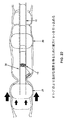
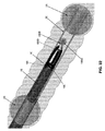
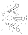
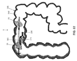
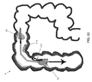
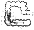
本発明によると、また、ここで図1を参照すると、内視鏡10(例えば、連接内視鏡)を使用する内視鏡的手技中に検査および/または治療のために側壁組織をより良好に提示すること(最初は視野から隠れているかまたは視野の外側にある領域の可視化を含む)を目的として、ならびに/あるいは、内視鏡10の遠位端ならびに/または他の器械(例えば、図1に図示されない、グラスパー、カッターまたは解剖器具、焼灼ツール、超音波プローブなど)の遠位側先端部および/もしくは作業端を安定させるために、身体管腔および/または体腔の側壁を操作(例えば、安定させる、まっすぐに伸ばす、膨らませる、および/または、平らにする、など)することができる新規な装置5が示されている。
(New device)
According to the present invention, and also with reference to FIG. 1, the side wall tissue is better for examination and / or treatment during an endoscopic procedure using an endoscope 10 (eg, a concatenated endoscope). For the purpose of presenting to (including visualization of areas initially hidden from or outside the field of view) and / or the distal end of the
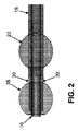
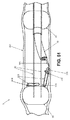
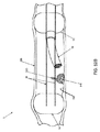
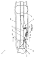
より具体的には、装置5が、概して、内視鏡10のシャフトの外側部分上で摺動させられるように適合されるスリーブ15と、スリーブの遠位端の近くでスリーブ15に固着される近位側(または、「後部」)バルーン20と(本明細書の以下において「近位側」および「後部」という用語は交換可能に使用される)、スリーブの近位端のところでスリーブ15に固着される基部25とを備える。装置5が、本明細書において後で考察するようにスリーブ15に摺動可能に設置される一対のプッシュチューブ30と、プッシュチューブ30の遠位端に固着される遠位側(または、「前方」)バルーン35と(本明細書の以下において「遠位側」および「前方」という用語は交換可能に使用される)、をさらに備え、その結果、後部バルーン20と前方バルーン35との間の間隔が、医師(または、他のオペレータもしくは使用者)により、スリーブ15を基準としてプッシュチューブ30を移動させることにより(例えば、プッシュチューブハンドル37のところで2つのプッシュチューブを同時に前進させることにより(下記を参照))、調整され得る。図1および2〜4を参照されたい。装置5が、医師(または、他のオペレータもしくは使用者)により後部バルーン20および前方バルーン35の一方または両方を選択的に膨張/収縮させるのを可能にするための連結される膨張機構40(図1)をさらに備える。
More specifically, the
次に図1〜6を参照すると、スリーブ15が、概して、内視鏡10のシャフトと締まり嵌めを形成するように内視鏡10のシャフトの外側部分上で摺動させられる(例えば、内視鏡の遠位側先端部から逆向きに)ように構成される細長い薄壁チューブを備え、ここでは、スリーブが内視鏡の上に設置される(好適には、スコープが「乾燥状態」である)ときに内視鏡の上で逆方向にも容易に摺動するが内視鏡の外側表面との十分な残留摩擦を有する(医師あるいは他のオペレータまたは使用者の手で握持されるとき)ように、サイズ決定および構成され、その結果、スリーブが、使用中に内視鏡にトルクを与える(すなわち、回転により旋回させる)ことおよび内視鏡を押す/引くこと(例えば、患者の結腸の中)を可能にするように定位置に留まるようになる。本発明の好適な一形態では、スリーブ15が内視鏡10の周りで円周状にいくらかの程度で移動することができる(さらに、医師あるいは他のオペレータまたは使用者の手でしっかりと握持されているときに、内視鏡のシャフトと共に回転することができる)。しかし、スリーブ15は名目上は内視鏡10を基準として軸方向にのみ移動することができる。スリーブ15は、その遠位端が内視鏡10の遠位端に実質的に位置合わせされるときに内視鏡のシャフトを実質的に覆うことになるように(基部25と共に)、サイズ決定される。いずれの場合も、スリーブ15は、スリーブ15が内視鏡10に設置されて内視鏡10が患者の中に挿入されるときに、患者の身体の外に出るように延在することになるように、サイズ決定される。本発明の好適な一形態では、装置5はそれが共に使用されることを意図される特定の内視鏡に従って提供され、ここでは、装置5は、基部25が内視鏡のハンドルに係合されているときのスリーブ15の遠位端を内視鏡のほぼ遠位端のところに配置することになるように、すなわち、内視鏡の遠位端に実質的に位置合わせするかまたは内視鏡の遠位端からわずかに近位側のところに位置合わせすることになるように、サイズ決定される。
Next, referring to FIGS. 1 to 6, the
所望される場合、スリーブ15の遠位端が、内視鏡10の遠位端表面に確実に係合される径方向内側に延在する停止部分(図示せず)を装備することができ、それにより、スリーブ15の遠位端が内視鏡10の遠位端表面を越えて近位側に移動することが防止される。このような径方向内側に延在する停止部分はまた、結腸内にあるときに内視鏡にトルクを与える(すなわち、回転により旋回させる)ときの内視鏡10に対してのスリーブ15の「トルクスリップ」を、および/または、結腸内にあるときに内視鏡を前方に押すときの内視鏡10に対してのスリーブ15の「スラストスリップ」を防止するのを補助することができる。
If desired, the distal end of the
スリーブ15は、好適には、組織に対して非外傷性となるように滑らかな外側表面を有し、好適には、可撓性の高い材料で作られ、その結果、使用中にスリーブが内視鏡を曲げるのを阻害しない。本発明の好適な一形態では、スリーブ15が、ポリウレタン、ポリエチレン、ポリ塩化ビニル(PVC)、ポリテトラフルオロエチレン(PTFE)などを含み、好適には、内視鏡10上の距離のマーキングをスリーブ15を通して可視化するのを可能にするために透明である(または、少なくとも半透明である)。また、本発明の好適な一形態では、スリーブ15が好適には公称のフープ強度を有し、その結果、医師(あるいは、他のオペレータまたは使用者)がスリーブ15を介して内視鏡10を握持することができ、それにより例えば内視鏡にトルクを与えることができる。所望される場合、スリーブ15が、その内部表面および/または外部表面の一部または全体の上に潤滑性のコーティング(例えば、ペルフルオロポリエーテルの合成油などの液体、粉末、など)を有することができ、それにより、内視鏡の上にスリーブを配置することならびに/あるいは身体管腔および/または体腔を通して装置5を移動させることを容易にする。別法として、スリーブ15が、例えばポリテトラフルオロエチレン(PTFE)などの、それ自体が潤滑性である材料で形成されてもよい。スリーブ15の内部の表面が、使用中に内視鏡を基準としてスリーブが回転するのを防止するための特徴(例えば、突出部)を有することができる、ことを認識されたい。
The
所望される場合、スリーブ15と内視鏡10との間に真空が「導入(pull)され」、それにより、スリーブ15を内視鏡10に固着し、スリーブ15のプロフィールを最小にする。限定しないが例えば、真空がスリーブ15の近位端のところに(すなわち、基部25のところに)導入され得るか、または、真空がスリーブ15の中間の位置に導入され得る。限定しないがさらなる例として、例えばスリーブ15の近位端のところ(すなわち、基部25)またはスリーブ15の中間のところで、スリーブ15と内視鏡10との間の空間に流体(例えば、空気、または、液体潤滑剤)を導入することにより、内視鏡10からスリーブ15を取り外すこと(例えば、手技の終了時)が容易になり得ることを認識されたい。
If desired, a vacuum is "pulled" between the
ここで図1〜6をさらに参照すると、後部バルーン20が、スリーブの遠位端の近くであるがスリーブの遠位端から離れた内視鏡の連接接合部の近位側のすぐ近くのところで、スリーブ15に固着される。後部バルーン20がスリーブ15を中心として同心に配置され、したがって、スリーブ15内に配置される内視鏡10を中心としても同心に配置される。したがって、後部バルーン20は概略ドーナツ形状を有する。後部バルーン20は、近位側の膨張/収縮チューブ45により選択的に膨張/収縮され得、近位側の膨張/収縮チューブ45の遠位端が後部バルーン20の内部に流体連通され、また、近位側の膨張/収縮チューブ45の近位端が、基部25に設置される装着具46に流体連通される。装着具46は、上で言及した連結される膨張機構40に接続されるように構成される。装着具46は好適にはルアー作動弁であり、後部バルーン20内の圧力を損失することなく膨張機構40を装着具46から外すのを可能にする。膨張/収縮チューブ45がスリーブ15の外部表面に固着され得、または、より好適には、膨張/収縮チューブ45が、スリーブ15内に形成される管腔47の中に含まれ得る。
Further referring to FIGS. 1-6, the
好適には、後部バルーン20がスリーブ15の遠位端から後方のわずかな距離のところに配置され、すなわち、操縦可能な内視鏡10の連接部分の長さとほぼ同じ距離のところに配置され、その結果、操縦可能な内視鏡がスリーブ15内に配置されるとき、操縦可能な内視鏡の連接部分が後部バルーン20の遠位側に配置されることになる。この構成は、本明細書において後でより詳細に考察するように、生体構造内で後部バルーン20が膨張させられた場合でも操縦可能な内視鏡の可撓性部分を連接するのを可能にし、それにより、内視鏡の隣接する非連接部分を生体構造を基準として安定させる。したがって、後部バルーン20は、膨張時、内視鏡10を身体管腔または体腔内の安定位置で維持するための堅固なプラットフォームを提供し、ここでは、内視鏡10が身体管腔または体腔の中心に配置される。その結果、内視鏡10が生体構造の可視化を改善することができる。さらに、膨張した後部バルーン20により内視鏡10が身体管腔または体腔内で堅固に維持されることから、内視鏡10の内部管腔(「作業チャンネル」と称される場合もある)を通して前進させられる器械が、やはり、身体管腔または体腔内でそれらの器械を支持するための堅固なプラットフォームを提供されることになる。
Preferably, the
後部バルーン20が適切に膨張される場合、後部バルーンが、装置5を中に配置しているところの身体管腔の側壁に非外傷的に係合されて身体管腔の側壁との密閉関係を形成することができる。
When the
本発明の好適な一形態では、後部バルーン20がポリウレタンから形成される。
In a preferred embodiment of the invention, the
基部25がスリーブ15の近位端に固着される。基部25が内視鏡10に係合され、組立体全体(すなわち、装置5)を内視鏡10に固着するのを補助する。基部25は、好適には、医師(あるいは、他のオペレータまたは使用者)によって握持され得るようなおよび近位側に引かれ得るような、実質的に剛体のまたは半剛体の構造を備え、それにより、医師(あるいは、他のオペレータまたは使用者)が内視鏡10の遠位端の上でスリーブ15を引いて内視鏡10の長さ方向に沿わせて近位側に戻すことが可能となり、それによりスリーブ15を内視鏡のシャフトの外側表面に設置する。本発明の好適な一形態では、基部25が内視鏡のハンドルに接触して着座するようになるまで、基部25が内視鏡に沿って近位側が引かれ、それにより基部25の近位側へのさらなる移動が妨げられる(ひいてはそれにより、スリーブ15の近位側へのさらなる移動が妨げられる)。本発明の好適な一形態では、基部25が内視鏡10との密閉係合を形成する。
The
プッシュチューブ30がスリーブ15に摺動可能に設置され、それにより、プッシュチューブの遠位端がスリーブ15を基準として延伸させられ得および/または引っ込められ得(例えば、プッシュチューブハンドル37を介してプッシュチューブを前進させるかまたは後退させることにより(下記を参照))、およびひいては、スリーブ15内に配置される内視鏡10の遠位端を基準として延伸させられ得るおよび/または引っ込められ得る。好適には、プッシュチューブ30が、スリーブ15の外側表面に固着される支持チューブ50内に摺動可能に配置されるか、または、より好適には、スリーブ15内に形成される管腔52内に含まれる。支持チューブ50が好適には、支持チューブ50を基準とするプッシュチューブ30の移動に対する抵抗を最小にするために(ひいては、スリーブ15を基準とするプッシュチューブ30の移動に対する抵抗を最小にするために)、低摩擦材料(例えば、「PTFE」としても知られるポリテトラフルオロエチレン)から形成される。これに関して、支持チューブ50を基準とするプッシュチューブ30の移動に対する抵抗を最小にすることが、前方バルーン35を操作するためのプッシュチューブ30の使用時の使用者に対する触覚フィードバックを改善する、ことを認識されたい。本発明の一形態では、支持チューブ50が可撓性であるが(手技中に必要に応じて、内視鏡10および特には操縦可能な内視鏡10の連接部分が湾曲するのを可能にするために)、支持チューブ50はある程度の柱強度も提供する。したがって、支持チューブ50がスリーブ15内に形成される管腔52内に設置される場合、スリーブ15と支持チューブ50との組立体が可撓性を有するが、一定程度の柱強度を有する(対して、スリーブ15のみでは可撓性を有するが、柱強度を実質的に有さない)。プッシュチューブ30がスリーブ15内に形成される管腔52内に含まれる場合、および、支持チューブ50がプッシュチューブ30と管腔52との間に配置されない場合、管腔52が好適には、プッシュチューブ30と管腔52との間の摩擦を最小にするために潤滑される。
The
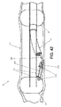
プッシュチューブ30の近位端がプッシュチューブハンドル37に接続される。この構成の結果として、プッシュチューブハンドル37を遠位側に押すことにより、プッシュチューブ30の遠位端がスリーブ15を基準として遠位側に(等しい変化量で)移動することになり(それにより、後部バルーン20を基準として前方バルーン35を遠位側に移動させる)、また、プッシュチューブハンドル37を近位側に引くことにより、プッシュチューブ30の遠位端がスリーブ15を基準として近位側に(等しい変化量で)引っ込められる(それにより、後部バルーン20を基準として前方バルーン35を近位側に移動させる)。プッシュチューブ30を等しい変化量で遠位側または近位側に移動させることにより、プッシュチューブの遠位端が互いに平行な状態で維持されることに留意されたい。クランプ53(図12および15)が、基部25を基準とした選択される配置(ひいては、スリーブ15を基準とした選択される配置)でプッシュチューブ30を保持するために基部25のところに設けられる。
The proximal end of the
プッシュチューブ30が、好適には、例えば、(オハイオ州、ウィックリフのルーブリゾール社から入手可能である)Isoplast(商標)などの熱可塑性ポリエチレン樹脂、ポリエチレン、ポリプロピレン、ナイロン、などの、良好な柱強度を提供する可撓性の比較的高い材料から形成される。プッシュチューブ30が単一の材料または複数の材料を含むことができること、ならびに、プッシュチューブ30のスティフネスがそれらの長さ方向に沿って変化してよいこと、を認識されたい。限定しないが例えば、プッシュチューブ30の最も遠位側の部分がプッシュチューブの残りの部分と同じ材料で形成され得るが、プッシュチューブの残りの部分より高い可撓性を有するようにより低いモジュラスを有してよい。あるいは、プッシュチューブ30の最も遠位側の部分がより高い弾性を有する別の可撓性材料を含むことができる。限定しないが例えば、プッシュチューブ30の最も遠位側の部分がNitinolを含むことができる。限定しないがさらなる例として、プッシュチューブ30の最も遠位側の部分が、ポリテトラフルオロエチレン(PTFE)の外側ジャケットで覆われるステンレス鋼コイルを備えることができ、ここでは、最も遠位側のジャケット/より近位側の管類が、一体に、前方バルーン35を膨張/収縮させるための密閉される管腔を提供する。プッシュチューブの残りの部分より高い可撓性を有する遠位端を有するようなプッシュチューブ30を形成することにより、後でさらに考察するように、プッシュチューブ30および前方バルーン35が、一体に、装置5および内視鏡10のためのリード(柔らかい非外傷性先端部を備える)として機能することができる。
The
本発明の好適な一形態では、プッシュチューブ30が、非付勢状態にあるときにすなわちプッシュチューブ30に力が加えられないときに、平行な配置を維持するように構成される。これは前方バルーン35の膨張状態または収縮状態に関係なく当てはまる。
In a preferred embodiment of the invention, the
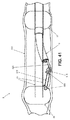
プッシュチューブ30の最も遠位側の部分が、所望される場合に、内側または外側に曲がるように構成され得る。このような構成を用いることにより、プッシュチューブ30の遠位端が静止した状態で保持され(例えば、本明細書において後で考察するように、膨張した前方バルーンにより)、遠位方向の十分な力がプッシュチューブ30に加えられ、プッシュチューブ30の中間部分(すなわち、膨張した前方バルーン35とスリーブ15との間の部分)が外側に曲がることができるかまたは外側に撓むことができ、それにより、装置5を中に配置しているところの身体管腔の側壁を外側に押し、それにより、後部バルーン20と前方バルーン35との間の空間において身体管腔および/または体腔の側壁に「テント」効果が得られる。この「テント」効果が、装置5を中に配置しているところの身体管腔および/または体腔の側壁を外側に押すことにより内視鏡10の遠位側の領域内の可視性および/または組織安定性を有意に向上させることができる。
The most distal portion of the
さらに、プッシュチューブ30を可撓性材料から形成することにより、患者の生体構造の可視化に対してプッシュチューブにより干渉することおよび/または前方バルーンと後部バルーンとの間の空間への診断ツールまたは治療ツールの導入に対してプッシュチューブにより干渉することを防止することを目的として、使用中にプッシュチューブ30の位置を手動で調整すること(例えば、別個のツールを使用することによって、装置にトルクを与えることによって、など)が可能となる、ことを認識されたい。限定しないが例えば、生体構造の標的領域までの視覚的アクセスまたは物理的アクセスをプッシュチューブ30により遮るような形で装置5が生体構造内に配置される場合、別個のツールもしくは器械を使用することにより、または、可撓性のプッシュチューブ30を邪魔にならないように移動させるようなトルクを与える動きで装置を回転させることなどにより、可撓性のプッシュチューブ30が邪魔にならないように移動させられ得る。限定しないがさらなる例として、円形であり、可撓性であり、内視鏡10の円周よりも有意に小さい直径を有するようにプッシュチューブ30を構成することにより、連接時に、円形の内視鏡を移動させることで、邪魔にならないようにプッシュチューブを単純に押すことができ、対象の組織までの遮るものがない視覚的経路が提供される。
In addition, by forming the
また、所望される場合、例えば色付きのインジケータまたはX線不透過性インジケータなどの、距離のマーカー(図には示されない)を含めたインジケータがプッシュチューブ30に付され得、その結果、内視鏡10を介してまたはX線誘導(例えば、X線透視法)により手術部位を観察している医師(あるいは、他のオペレータまたは使用者)が、身体管腔および/または他の体腔の側壁を基準とした長手方向および/または円周方向の両方における、手術部位のところにあるプッシュチューブ30の相対的な配置を確認することができる、ことを認識されたい。
Also, if desired, an indicator containing a distance marker (not shown), such as a colored indicator or an X-ray opaque indicator, may be attached to the
本明細書の以下においてさらに詳細に考察されるように、プッシュチューブ30が中空であり、前方バルーン35(図1〜5、7および8)の内部に流体連通されるそれらの遠位端、および基部25に設置される装着具56に流体連通されるそれらの内部管腔を有する。装着具56は上で言及した連結される膨張機構40に接続されるように構成され、その結果、前方バルーン35が空気または他の流体(液体を含む)を用いて選択的に膨張/収縮され得るようになる。装着具56は好適にはルアー作動弁であり、前方バルーン35内の圧力を損失することなく膨張機構40を装着具56から外すのを可能にする。
As discussed in more detail below herein, the
より具体的には、本発明の好適な一形態で、また、次に図8Aを参照すると、プッシュチューブハンドル37が中空内部57を備える。プッシュチューブ30がプッシュチューブハンドル37に設置され、その結果、プッシュチューブ30がプッシュチューブハンドル37に連動して移動することになり、またさらには、プッシュチューブ30の中空内部がプッシュチューブハンドル37の中空内部57に流体連通されることになる。プッシュチューブハンドル37が、プッシュチューブハンドル37の中空内部57に流体連通される装着具58をさらに備える。可撓性チューブ59が、基部25内に内部チャンバ(図示せず)を有するような形で、装着具58に接続され、ここでは基部25内のこの内部チャンバが上で言及した装着具56に流体連通される。この構成の結果として、プッシュチューブハンドル37が遠位側に移動させられる場合、前方バルーン35が遠位側に移動させられることになり、また、プッシュチューブハンドル37が近位側に移動させられる場合、前方バルーン35が近位側に移動させられることになる。さらに、陽圧である流体圧力が基部25内の装着具56に加えられる場合、陽圧である流体圧力が前方バルーン35の内部管腔に加えられ、それにより前方バルーン35を膨張させ、また、陰圧である流体圧力が基部25内の装着具56に加えられる場合、陰圧である流体圧力が前方バルーン35の内部管腔に加えられ、それにより前方バルーン35を収縮させる。
More specifically, in a preferred embodiment of the invention, and with reference to FIG. 8A, the push tube handle 37 comprises a hollow interior 57. The
デュアルプッシュチューブを設けることによって多くの利点が得られることを認識されたい。限定しないが例えば、デュアルプッシュチューブを設けることにより、本明細書において後で考察するように、前方バルーンが遠位側に前進させられて身体管腔に入れられるときに前方バルーン35に対称の力が加えられることになる。さらに、デュアルプッシュチューブ30が設けられることにより、本明細書において後で考察するように、内視鏡10の遠位端に近傍の領域内の生体構造をまっすぐに伸ばすのにプッシュチューブが採用される場合に隣接する生体構造に対して等しい外向きの力が提供され、それにより、生体構造の可視化および/または生体構造へのアクセスを向上させる。加えて、デュアルプッシュチューブが設けられることにより、本明細書において後で考察するように、前方バルーン35が内視鏡10上で中心に配置された状態を確実に維持するようになり、それにより前方バルーン35を内視鏡10から切り離すことおよび前方バルーン35を内視鏡10上に再合体させることが容易になる。加えて、デュアルプッシュチューブ30が設けられることにより、内視鏡の先端部を基準として前方バルーン35を確実に安定させることが補助され、それにより膨張時の前方バルーンの回転運動が最小となる。さらに、中空のデュアルプッシュチューブが設けられることにより、前方バルーン35を膨張または収縮させるための重複的な空気移送システムが提供されることになる。
Please be aware that there are many benefits to having a dual push tube. For example, by providing a dual push tube, a force symmetrical to the
前方バルーン35がプッシュチューブ30の遠位端に固着され、それにより、スリーブ15を基準としてプッシュチューブ30を移動させることにより、すなわち、スリーブ15を基準としてプッシュチューブハンドル37を移動させることにより、後部バルーン20と前方バルーン35との間の間隔が調整され得るようになる。さらに、中空プッシュチューブ30が前方バルーン35の内部と装着具56との間に導管を提供し、それにより、装着具56を介して前方バルーン35を選択的に膨張/収縮させるのを可能にする。
The
重要なことには、前方バルーン35が結果として以下のようになるように構成される:(i)収縮されており(または、部分的に収縮されており)スリーブ15を基準としてその「後退」位置にある場合に(図2)、前方バルーン35が、スリーブ15および内視鏡10のシャフトをその中に受け入れるのに十分である軸方向開口部63(図7、8および10)を提供し、それにより、前方バルーン35がスリーブ15および内視鏡10の上に「合体」し得るようになる;(ii)前方バルーン35がスリーブ15を基準としてその「延伸」位置にあり、適切に膨張されている場合に(図4)、軸方向開口部63が閉じられる(また好適には、完全に閉鎖される)。また同時に、適切に膨張されている場合、前方バルーンが、装置5を中に配置しているところの身体管腔および/または体腔の側壁に非外傷的に係合されて身体管腔および/または体腔の側壁と密閉関係を形成することができる。したがって、前方バルーン35が適切に膨張される場合、前方バルーンが、軸方向開口部63を閉じて装置5を中に配置しているところの身体管腔および/または体腔の側壁との密閉関係を形成することにより、前方バルーン35の遠位側で身体管腔および/または体腔を効果的に密閉することができる。こうすることで、プッシュチューブ30が遠位側に前進させられて前方バルーン35を後部バルーン20から分離する場合に、ならびに、前方バルーン35および後部バルーン20が適切に膨張される場合に、2つのバルーンがそれらの間に密閉ゾーンを形成することになる(本明細書の以下において「治療ゾーン」と称される場合もある)。
Importantly, the
前方バルーン35がその収縮状態からその膨張状態へと再構成される場合、前方バルーン35が径方向内側に膨らみ(それにより軸方向開口部63を閉じる)さらには径方向外側に膨らむ(それにより周辺組織に係合される)、ことが認識されよう。
When the
したがって、前方バルーン35が収縮時に「トーラス」形状を有し(それにより、内視鏡の遠位端上に着座することが可能となる)、膨張時に実質的に「中実」の形状を有する(それにより、身体管腔または体腔を閉鎖することが可能となる)、ことが分かるであろう。
Thus, the
この目的のため、次に図9および10を参照すると、前方バルーン35が好適には、近位側開口部69および遠位側開口部71を有するボディ67と、ローブ74を有する「キー形状」断面を有する近位側延長部分73と、円形断面を有する遠位側延長部分76と、を備える単一構成として製造される。プッシュチューブ30の構成に適合する構成を有するようにローブ74が近位側延長部分73上に配置されることに留意されたい(すなわち、装置5が互いに径方向反対側にある2つのプッシュチューブ30を備える場合、近位側延長部分73が互いに径方向反対側にある2つのローブ74を備えることになり;装置5がスリーブ15の境界を中心として円周方向において均等である3つのプッシュチューブ30を備える場合、近位側延長部分73が近位側延長部分73の境界を中心として円周方向に均等である3つのローブ74を備えることになり、装置5が1つのプッシュチューブ30を備える場合、近位側延長部分73が1つのローブ74を備えることになる、などである)(本発明では、近位側延長部分73およびローブ74がまとめて「キー形状」断面を有するものとして称されてもよい))。組み立て中、プッシュチューブ30が近位側延長部分73のローブ74内に着座し、近位側延長部分73が反転されてボディ67の内部に入れられ(ここでは、中空プッシュチューブ30の内部がボディ67の内部に流体連通される)、さらに、遠位側延長部分76が反転されて近位側延長部分73の内部に入れられ、それによりそこを通って延在する軸方向開口部63を有する前方バルーン35が提供されることになり、ここではプッシュチューブ30が前方バルーン35に固着され、前方バルーン35の内部に連通される。重要なことには、軸方向開口部63が内視鏡10の遠位端を中で受けるようにサイズ決定される。やはり重要なことには、近位側延長部分73を反転させてボディ67の内部に入れてさらに遠位側延長部分76を反転させて近位側延長部分73の内部に入れる上で言及したプロセスにより、前方バルーン35を形成することで、プッシュチューブ30の周りに複数の層のバルーン材料が提供されることになり、それにより、より高いロバスト性を有するバルーン構成が提供されることになる。とりわけ、プッシュチューブ30の周りに複数の層のバルーン材料を提供することでプッシュチューブ30の遠位端にクッション性が加えられ、それにより、より高い非外傷性を有する遠位側先端部がプッシュチューブ30に提供されることになり、さらに、プッシュチューブ30の遠位側先端部が隣接する組織にダメージを与えないことを保証する。
For this purpose, then with reference to FIGS. 9 and 10, the
本発明の好適な一形態では、前方バルーン35がポリウレタンから形成される。
In a preferred embodiment of the invention, the
前方バルーン35がその収縮状態にある場合に前方バルーン35の材料がプッシュチューブ30の遠位端を実質的に取り囲み(この間、依然として、プッシュチューブ30を前方バルーン35の内部に流体連通するのを可能にする)、それにより身体管腔を通して前方バルーン35を遠位側に前進させるための非外傷性先端部が提供されることを認識されたい。さらに、プッシュチューブ30および収縮した前方バルーン35が、後でさらに考察するように(図20)、一体に、装置5および内視鏡10のための柔らかい先端部を有するリードとして本質的に機能することができる。
When the
所望される場合、前方バルーン20および後部バルーン35の一方または両方にインジケータ(例えば、カラーインジケータまたはX線不透過性インジケータ)が付され得、その結果、内視鏡10を介してまたはX線誘導(例えば、X線透視法)により手術部位を観察している医師(あるいは、他のオペレータまたは使用者)が、手術部位でのこれらのバルーンのうちの一方または両方の配置を確認することができる。
If desired, one or both of the
膨張機構40が後部バルーン20および/または前方バルーン35を選択的に膨張させるための手段を提供する。
The
本発明の好適な一形態では、また、次に図1および11を参照すると、膨張機構40が、ボディ145と、プランジャ150とを備える一直線状のシリンジインサータ140を備える。好適には、ばね153がプランジャ150をそのストロークの端部のところに自動で戻すためにボディ145内に設けられる。シリンジインサータ140がライン155を介して装着具46、56のうちの一方またはもう一方に接続される。したがって、このような構成を用いる場合、一直線状のシリンジインサータ140が後部バルーン20を膨張させるのに使用されることになる場合、シリンジインサータ140がライン155を介して装着具46に接続され、その結果、一直線状のシリンジインサータ140のアウトプットが後部バルーン20に誘導される(すなわち、近位側の膨張/収縮チューブ45を介する)。対応して、一直線状のシリンジインサータ140が前方バルーン35を膨張させるのに使用されることになる場合、シリンジインサータ140がライン155を介して装着具56に接続され、その結果、一直線状のシリンジインサータ140のアウトプットが前方バルーン35に誘導される(すなわち、可撓性チューブ59およびプッシュチューブ30の中空内部を介する)。
In a preferred embodiment of the invention, and also with reference to FIGS. 1 and 11, the
本発明の別の好適な形態で、膨張機構40が、第1のポート157および第2のポート158を有する弾性球状部分156を備える。一方向弁159(例えば、逆止弁)が第1のポート157内に配置され、その結果、外側方向に移動するときに空気が第1のポート157のみを通過することができる。別の一方向弁159(例えば、逆止弁)が第2のポート158内に配置され、その結果、内側方向に移動するときに空気が第2のポート158のみを通過することができる。弾性球状部分156が圧縮されると(例えば、手により)、弾性球状部分156の内部の空気が第1のポート157から押し出され、その後で弾性球状部分156が解放されると、空気が第2のポート158を通して弾性球状部分156の内部に引き戻される。
In another preferred embodiment of the invention, the
この構成の結果として、弾性球状部分156が後部バルーン20を膨張させるのに使用されることになる場合、第1のポート157がライン155を介して装着具46に接続され、その結果、弾性球状部分156の陽圧のアウトプットが後部バルーン20に誘導される。その後、弾性球状部分156が後部バルーン20を収縮させるのに使用され得、すなわち、ライン155を介して第2の部分158を装着具46に接続することにより、弾性球状部分156の吸引力が後部バルーン20に誘導される。対応して、弾性球状部分156が前方バルーン35を膨張させるのに使用されることになる場合、第1のポート157がライン155を介して装着具56に接続され、その結果、弾性球状部分156の陽圧のアウトプットが前方バルーン35に誘導される。その後、弾性球状部分156が前方バルーン35を収縮させるのに使用され得、すなわち、ライン155を介して第2のポート158を装着具56に接続することにより、弾性球状部分156の吸引力が前方バルーン35に誘導される。
If, as a result of this configuration, the elastic
別法として、また、次に図12および13を参照すると、シリンジ160が後部バルーン20および/または前方バルーン35を膨張させるのに使用され得る。膨張機構160がボディ161およびプランジャ162を備える。好適には、ばね(図示せず)が、プランジャ162をその動力行程の端部のところに自動で戻すためにボディ161内に設けられる。シリンジ160がライン163を介して装着具46、56に接続される。この構成を用いる場合、シリンジ160が、シリンジ160を前方バルーン35または後部バルーン20に接続するための弁165と、接続されたバルーンの膨張または収縮を選択するための弁170と、を備える。
Alternatively, and then with reference to FIGS. 12 and 13, the
したがって、この構成を用いる場合、シリンジ160が後部バルーン20を膨張させるのに使用されることになる場合、弁165(弁170を前方バルーンまたは後部バルーンのいずれかに接続する二位置弁)が、装着具46を通してシリンジ160を後部バルーン20に接続するような形となるように、設定され、弁170(一方の構成において膨張させてもう一方の構成において収縮させるように一方向弁を配置するのを可能にする双方向のクロスオーバー弁)が、シリンジ160により膨張圧力を提供するような形となるように、設定される。その後、後部バルーン20が収縮されることになる場合、弁170がその収縮位置にくるように設定される。
Therefore, when using this configuration, if the
対応して、シリンジ160が前方バルーン35を膨張させるのに使用されることになる場合、弁165が、装着具56を通してシリンジ160を前方バルーン35に接続するような形となるように、設定され、弁170が、シリンジ160により膨張圧力を提供するような形となるように、設定される。その後、前方バルーン35が収縮されることになる場合、弁170がその収縮位置にくるように設定される。
Correspondingly, if the
本発明のさらに別の形態では、膨張機構40が例えば電気ポンプなどの自動の流体圧力源(陽圧または陰圧のいずれか)を備えることができる。
In yet another embodiment of the invention, the
所望される場合、また、次に図14を参照すると、逃し弁175が、前方バルーン35内の圧力が所定のレベルを確実に超えないようにするために、前方バルーン35に接続される膨張/収縮ラインに接続され得る。同様に、次にさらに図14を参照すると、逃し弁180が、後部バルーン20内の圧力が所定のレベルを確実に超えないようにするために、後部バルーン20に接続される膨張/収縮ラインに接続され得る。
If desired, and then with reference to FIG. 14, the relief valve 175 is inflated / connected to the
別法としておよび/または加えて、1つまたは複数の圧力計182(図1または図13)が、後部バルーン20に接続される流体ラインおよび/または前方バルーン35に接続される流体ラインに組み込まれ得、それにより後部バルーン20および/または前方バルーン35の内部の圧力に関する情報を医師(あるいは、他のオペレータまたは使用者)に提供し、それにより、過度の膨張を回避し、および/または、手技中のバルーンの膨張状態を医師(あるいは、他のオペレータまたは使用者)が確認するのを補助する。
Alternatively and / or in addition, one or more pressure gauges 182 (FIG. 1 or 13) are incorporated into the fluid line connected to the
さらに、前方バルーン35がその「後退」位置(図2)とその「延伸」位置(図4)との間を移動するとき、プッシュチューブ30を基部25(ひいては、装着具56)に接続する可撓性チューブ59が基部25の周りに集まる可能性があり、それにより可能性として医師(あるいは、他のオペレータまたは使用者)の動作に干渉する、ことが認識されよう。したがって、所望される場合、また、次に図15を参照すると、前方バルーン35の延伸時に可撓性チューブ59内のたるみを取るために、可撓性チューブ後退システム185が設けられ得る(例えば、基部25内)。
Further, when the
(新規な装置を使用する好適な方法)
装置5が、内視鏡10を使用する内視鏡的手技中に検査および/または治療のために側壁組織をより良好に提示すること(最初は視野から隠れているかまたは視野の外側にある領域の可視化を含む)を目的として、ならびに/あるいは、例えば治療ゾーンの中へと前進させられた、器械(例えば、グラスパー、カッターまたは解剖器具、焼灼ツール、超音波プローブなど)の遠位側先端部および/または作業端を安定させることを目的として、身体管腔および/または体腔の側壁を操作(例えば、安定させる、まっすぐに伸ばす、膨らませる、および/または、平らにする、など)するのに使用され得る。
(Preferable way to use new equipment)
The
より具体的には、使用時、最初に、スリーブ15が内視鏡10に設置される(図1)。これが、スリーブ15の遠位端を内視鏡10の遠位側先端部に実質的に位置合わせするまで、基部25を内視鏡10の遠位端上で近位側に引いて次いで内視鏡10の長さ方向に沿って近位側に引くことにより、達成され得る。この時点では、後部バルーン20が収縮されており、前方バルーン35が収縮されており、前方バルーン35が内視鏡10の遠位端の上に合体している。内視鏡10および装置5がユニットとして患者の中に挿入される準備が整う。
More specifically, at the time of use, the
次に図16を参照すると、内視鏡10および装置5がユニットとして患者の身体管腔および/または体腔内に挿入されている。限定しないが例えば、内視鏡10および装置5がユニットとして患者の胃腸(GI)管の中に挿入される。内視鏡10および装置5が身体管腔および/または体腔に沿って患者の中の所望のロケーションまで前進させられる(図17および18)。
Next, referring to FIG. 16, the
装置5が使用されることになる場合(例えば、胃腸管の側壁の可視化を向上させることを目的としておよび/または当該側壁のアクセスを向上させることを目的として、ならびに/あるいは、当該側壁を基準として器械を安定させることを目的として、胃腸管の側壁を操作するために)、身体管腔および/または体腔内で装置5(ひいては、内視鏡10)を安定させるために後部バルーン20が膨張される。図19を参照されたい。これが、上で言及した連結される膨張機構40を使用して行われ得る。
When
この点に関して、内視鏡の連接部分が後部バルーン20の遠位側に存在することを理由として、後部バルーン20が膨張された後でも、内視鏡が生体構造の可視化を促進するために後部バルーン20の遠位側で連接され得る、ことが認識されよう。重要なことには、後部バルーン20が胃腸管内で内視鏡10を安定させ、結腸を広げて結腸を後部バルーン20に直接に隣接する固定される直径まで大きくすることを理由として、このような可視化が改善される。
In this regard, because the connecting portion of the endoscope is on the distal side of the
次いで、プッシュチューブハンドル37を遠位側に押すことにより、プッシュチューブ30が身体管腔および/または体腔内で遠位側に前進させられる(すなわち、後部バルーン20のさらに前方にある前方バルーン35を移動させるために)。したがって、プッシュチューブ30およびひいては前方バルーン35が内視鏡10(膨張した後部バルーン20により胃腸管内の定位置で安定されている)を基準として遠位側に移動する。前方バルーン35のこのような遠位側への前進中、収縮した前方バルーン35がプッシュチューブ30の遠位端を覆っており、それにより前方バルーン35を確実に非外傷的に前進させるようになる、ことに留意されたい。より高い弾性を有する材料からプッシュチューブ30の遠位端を形成することにより、前方バルーン35の非外傷的な前進がさらに改善され得る、ことに留意されたい。
The push tube handle 37 is then pushed distally to advance the
プッシュチューブ30が内視鏡10の遠位側の所望の位置まで前方バルーン35を前進させた場合、前方バルーン35が膨張され(図20)、それにより前方バルーン35を生体構造に固着する。やはりこれも、上で言及した連結される膨張機構40を使用して行われ得る。前方バルーン35が膨張されるとき、膨張した前方バルーン35、膨張した後部バルーン20およびプッシュチューブ30のすべてが互いに対して相補的となり、それにより、内視鏡10を使用する内視鏡的手技中に検査および/または治療のために側壁組織をより良好に提示すること(最初は視野から隠れているかまたは視野の外側にある領域の可視化を含む)を目的として、身体管腔および/または体腔の側壁を安定させ、まっすぐに伸ばし、膨らませ、および/または、平らにする。この点に関して、膨張した前方バルーン35および膨張した後部バルーン20が共に身体管腔および/または体腔の側壁を膨らませてその側壁に張力を与えることになり、また、前方バルーンが後部バルーンから遠位側に延伸されるときに、プッシュチューブ30が2つの膨張したバルーンの間の生体構造をまっすぐに伸ばす傾向を有するようになる、ことを認識されよう。また、この点に関して、後部バルーン20および前方バルーン35の両方が膨張させられると、前方バルーン35が身体管腔および/または体腔の全体にわたる実質的に全直径の密閉を形成することになり(その理由は、膨張した前方バルーンが、その収縮状態時には前方バルーンを通って延在する軸方向開口部63を閉じるからである)、また、後部バルーン20がスリーブ15および内視鏡10と協働して身体管腔および/または体腔の全体にわたる実質的に全直径の別のバリアを形成することになる、ことを認識されよう。したがって、膨張した前方バルーン35および膨張した後部バルーン20が共に身体管腔および/または体腔に沿う実質的に閉じた領域を画定することになる(すなわち、膨張した前方バルーン35および後部バルーン20によって確立される気密密閉により、流体および/または他の液体を通過させるのを防止するような隔離される治療ゾーン)。前方バルーン35および後部バルーン20が膨張することにより身体管腔および/または体腔の側壁が張力を与えられることになり、それにより、内視鏡10を通した視認のために身体管腔および/または体腔の側壁をより良好に提示するようになる。
When the
膨張した前方バルーン35、膨張した後部バルーン20およびプッシュチューブ30により実現される、身体管腔および/または体腔の側壁を膨らませることおよびその側壁に張力を与えることが、前方バルーンが膨張されて身体管腔および/または体腔の側壁を握持しているときに前方バルーンを前進させることにより、さらに改善され得、それにより、身体管腔および/または体腔の側壁にさらに張力を与える、ことを認識されたい。
Inflating the body cavity and / or the side wall of the body cavity and applying tension to the side wall, realized by the inflated
重要なことには、膨張した前方バルーン35および膨張した後部バルーン20が共に身体管腔および/または体腔に沿う実質的に閉じた領域(すなわち、隔離された治療ゾーン)を画定することを理由として、その後で、この領域が、身体管腔および/または体腔の側壁にさらに張力を与えるために流体(例えば、空気、CO2、など)を用いて膨張され得(図21)、それにより、より正確な治療的介入を促進するように、内視鏡10を通した視認のために身体管腔および/または体腔の側壁をより良好に提示することができ、また、側壁を安定させることができる。
Importantly, because the inflated
所望される場合、前方バルーン35が膨張した状態を維持しながら(ひいては、身体管腔および/または体腔の側壁を握持した状態を維持しながら)後部バルーン20に向かって引っ込められ得(すなわち、プッシュチューブハンドル37を近位側に引くことにより)、それにより可視である粘膜を移動させて可視化およびアクセスをさらに改善し(図22を参照)、例えばそれにより、身体管腔および/または体腔の側壁上の特定の標的領域を、内視鏡および内視鏡的ツールを基準として好都合な角度となるように位置決めする。
If desired, the
別法として、所望される場合、後部バルーン35が膨張されると、プッシュチューブ30がそれらの遠位側への完全なストロークのうちの一部分(ただし一部分のみ)にわたって遠位側に前進させられ得、次いで前方バルーン35が膨張され得、それにより身体管腔および/または体腔の側壁を握持し、次いで、プッシュチューブ30がさらに遠位側に前進させられ得る。この動作により、可撓性のプッシュチューブ30が外側に撓むようになり(図22A〜22Dを参照)、例えば「テント」のような形で、身体管腔および/または体腔の側壁に接触して身体管腔および/または体腔の側壁を外側に押し、それにより、内視鏡10による身体管腔および/または体腔の側壁の可視化をさらに改善する。
Alternatively, if desired, when the
所望される場合、器械190(図23)が、病的状態を生検および/または治療するために(例えば、病的生体構造を摘出するために)内視鏡10の作業チャンネルを通って前進させられ得る。後部バルーン20を介して生体構造を基準として効果的に安定されるこうした器械が内視鏡の遠位端を通って延伸することになり、その結果、器械190の作業端も生体構造を基準としてさらに安定されることになる、ことが認識されよう。これは、内視鏡の安定していない端部から外へと器械を前進させるような従来技術の実施法よりも非常に有利である。好適には、器械190が完全な可動範囲を有する連接器械を有し、それにより標的生体構造までより良好にアクセスするようになる。
If desired, instrument 190 (FIG. 23) advances through the working channel of
さらに、出血が組織部位を不明瞭にするような場合または出血が起こって外科医が出血元を特定することができないような場合、隔離された治療ゾーンが、その治療ゾーンの位置するところの解剖学的セグメントを迅速に洗浄する(例えば、塩水などの液体を用いる)のを可能にし、その後で洗浄液を迅速に取り除く(図24〜26を参照)。 In addition, if the bleeding obscures the tissue site or if the bleeding occurs and the surgeon cannot determine the source of the bleeding, the isolated treatment zone is the anatomy where the treatment zone is located. Allows rapid cleaning of the target segment (using a liquid such as salt water), followed by rapid removal of the cleaning fluid (see FIGS. 24-26).
また、所望される場合、前方バルーン35が高い精度で出血部位まで誘導され得、その後、前方バルーン35が、出血の制御を改善するために出血部位に局部圧力を加えるのに使用され得る(例えば、膨張され得る)(図27を参照)。これが、内視鏡10によって実現される可視化のもとで行われ得る。
Also, if desired, the
装置5からの干渉を最小にして内視鏡10を生体構造内で再配置することが望まれる場合、前方バルーン35がそのトーラス構成(すなわち、部分的に収縮した状態)へと戻され、前方バルーンが近位側に引っ込められて内視鏡10の遠位端上に「再合体」し、後部バルーン20が収縮され、内視鏡10(その上で担持される装置5と共に)が生体構造内で再配置される。前方バルーン35が内視鏡10の遠位端上に再合体することになる場合、前方バルーン35が内視鏡の遠位端上に再合体するまで、前方バルーン35が好適には部分的にのみ収縮される、ことに留意されたい。その理由は、前方バルーン35が部分的に膨張していることで、前方バルーン35が再合体プロセスを促進するのに十分な「ボディ」を有したままにすることができるからである。その後、所望される場合に前方バルーン35が完全に収縮され得、それにより例えば、内視鏡10の遠位端を確実に握持する。
If it is desired to reposition the
別法として、所望される場合、前方バルーン35が内視鏡の逆向運動を制御するためのドラッグブレーキとして使用され得る。より具体的には、本発明のこの形態では、内視鏡の先端部が適切なロケーションのところにくるまで、最初に、内視鏡10および装置5がユニットとして身体管腔および/または体腔の中へと前進させられる。次いで、後部バルーン20が膨張され、プッシュチューブ30が遠位側に前進させられ、前方バルーン35が膨張される(図28)。次いで、可視化および任意選択の治療処置がそのロケーションで実施され得る。装置が逆向きに移動させられることになる場合、後部バルーン20が収縮され、前方バルーン35が部分的に収縮され、内視鏡が近位側に後退させられ、それにより、身体管腔および/または体腔に沿って半膨張状態の前方バルーン35を引っ張り(図29)、ここでは、内視鏡が近位側に引かれるときに前方バルーン35がブレーキのようなものとして機能し、それにより、内視鏡をより制御する形で逆向きに移動させることが可能となり、ひいては生体構造をより良好に可視化することが可能となる。何らかの時点で、所望される場合、後部バルーン20および前方バルーン35が図30に示されるように再膨張され得、ここでは、2つのバルーンの間に確立される「隔離された治療ゾーン」に流体を導入してもしなくてもよく、それにより、生体構造を安定させ、まっすぐに伸ばし、膨らませ、および/または、平らにする。
Alternatively, if desired, the
また、単独で、または、前方バルーン35の上で言及した制動動作との組み合わせで、生体構造から内視鏡(ひいては、装置5)を後退させるときのブレーキとして後部バルーン20を使用することが可能である。
It is also possible to use the
手技の最後に、内視鏡10および装置5が生体構造から後退させられる。好適には、これが、前方バルーン35を収縮させ(または、部分的に収縮させ)、前方バルーン35を内視鏡10の遠位端上に「再合体」させるようにプッシュチューブ30を引っ込め、前方バルーン35により内視鏡の遠位端を握持することになるように前方バルーン35を完全に収縮させ、後部バルーン20を収縮させ(後部バルーン20がまだ収縮されていない場合)、内視鏡10および装置5をユニットとして生体構造から後退させることにより、行われる。
At the end of the procedure, the
装置5が、有利には、上で開示した手法以外の種々の手法でも使用され得ることを認識されたい。限定しないが例えば、内視鏡10(および、装置5)が結腸内で前進させられることになる場合、最初に、内視鏡の視覚的誘導下で前方バルーン35を遠位側に突出させることが望まれる可能性があり、その結果、前方バルーン35が内視鏡の遠位端に繋がれる。その結果、前方バルーン35を収縮させた状態(または、部分的に収縮させた状態)で内視鏡を遠位側に前進させる場合、前方バルーンおよび可撓性のプッシュチューブ30が、結腸を通る内視鏡の前進時の内視鏡のための非外傷性のリード(誘導構造)として機能することができる。重要なことには、プッシュチューブ30の遠位端が好適には高い可撓性を有することを理由として、前進する前方バルーン35が結腸壁に接触するとき(例えば、結腸の方向転換部分のところで)、可撓性のプッシュチューブが屈折することができ、その結果、前方バルーンが結腸の経路をたどることができ、それにより、結腸に沿って内視鏡を非外傷的に前進させるのを補助する。また、装置5が、有利には、それ以外であれば実施することが現在困難であるような管腔表面のさらなる検査を行うのを容易にするために他の手法でも使用され得ることを認識されたい。このような例として、流体で充填された膨張した前方バルーンおよび超音波プローブの検査によって促進されるような管腔の超音波内視鏡検査がある。
It should be recognized that the
(追加の構成)
所望される場合、装置5が、互いに独立してさらには互いに同時に、プッシュチューブ30を前進させることができるようにまたは引っ込めることができるように、構成され得、このようにプッシュチューブ30を独立して前進させることによりまたは引っ込めることにより、身体管腔および/または体腔を通過させるように、部分的に収縮したかまたは完全に収縮した前方バルーン35を操縦するのを補助することができ、それにより身体管腔および/または体腔を通過させるように内視鏡10を前進させるのをまたは引っ込めるのを容易にすることができ、ならびに/あるいは、このようにプッシュチューブ30を独立して前進させることによりまたは引っ込めることにより、膨張した前方バルーン35を用いて生体構造に「旋回力」を加えることを容易なものとすることができ、それにより可視化および/または治療のために生体構造をより良好に提示することができるようになる。
(Additional configuration)
If desired, the
限定しないが例えば、本発明のこの形態では、また、次に図30Aを参照すると、プッシュチューブ30の各々が、独立して、プッシュチューブハンドル37に摺動可能に設置され、その結果、プッシュチューブ30がプッシュチューブハンドル37から独立してさらには互いに独立して移動することができるようになる。停止部分191がプッシュチューブハンドル37を基準としたプッシュチューブ30の遠位側への移動を制限し、その結果、プッシュチューブがプッシュチューブハンドル37から完全に出るように移動させられ得ないようになる。この構成の結果として、前方バルーン35が遠位側に移動させられることになる場合、プッシュチューブ30が、一体に、または互いに独立して、遠位側に移動させられる。また、前方バルーン35が近位側に移動させられることになる場合、プッシュチューブ30が、一体にまたは互いに独立して、近位側に移動させられる。手技の任意の時点において、例えば前方バルーン35が膨張されて生体構造に係合される場合などで、プッシュチューブ30が互いに独立して移動させられ得、それにより、前方バルーンを「旋回」させ、それにより生体構造に「旋回力」を加え、またはこれは例えば前方バルーン35が部分的に膨張されて前進する組立体のために非外傷性先端部として使用される場合などであり、この場合、それにより、生体構造を通過させるように組立体を「操縦」するのを補助する。前方バルーン35の過度の旋回、ならびに/あるいは、プッシュロッドの交差、および/または、プッシュロッドのもつれ、および/または、プッシュロッドの位置のずれ、などを防止することを目的として、プッシュロッド30を互いに独立させて長手方向に移動させることができる程度を制限するための制限機構を提供することが望ましい可能性があることに留意されたい。また、プッシュチューブ30を上で言及したクランプ53内に設置することによりプッシュチューブ30が特定の配置で保持され得ることに留意されたい(図12および15)。
For example, but not limited to, in this embodiment of the invention, and also with reference to FIG. 30A, each of the
さらに、内視鏡10の外部において器械(または、中空の器械誘導チューブ)を支持するためにスリーブ15の構成を修正することが可能であることを認識されたい。より具体的には、再び図5および6を参照すると、図5および6に示される構成において、スリーブ15が、後部バルーン20を膨張/収縮させるための膨張/収縮チューブ45を受けるための管腔47と、前方バルーン35を操作するためのおよび膨張/収縮させるためのプッシュチューブ30を受ける支持チューブ50を受けるための一対の管腔52と、を備えることが分かるであろう。しかし、所望される場合、スリーブ15が、内視鏡10の外部において器械(または、中空の器械誘導チューブ)を支持するための追加の管腔を有することも可能である。
Further, it should be recognized that it is possible to modify the configuration of the
より具体的には、次に図31を参照すると、器械190を摺動可能に中で受けるための複数の管腔195を有するスリーブ15の別の形態の端面図が示されている。膨張時に後部バルーン20が身体管腔または体腔内で内視鏡10およびスリーブ15を維持するための堅固なプラットフォームを提供し、ここでは、内視鏡10およびスリーブ15が身体管腔または体腔内の中心に配置される、ことに留意されたい。その結果、スリーブ15の管腔195の遠位端も身体管腔または体腔内で固定的に維持されるようになり、それにより、スリーブ15の管腔195を通って前進させられる器械のための堅固な支持体を提供することになる。
More specifically, with reference to FIG. 31, an end view of another form of the
管腔195の近位端が基部25までおよび基部25を通るように延在してよく、この場合には器械が基部25のところで管腔195の中に挿入され得、または、管腔195の近位端が基部25の近位側で終端してもよく(それでも、患者の身体の外部において)、この場合には器械がスリーブ15の中間において管腔195の中に挿入され得る。限定しないが例えば、内視鏡10の長さが180cmであり、器械190の長さが60cmである場合、バルーン20、35により近いポイント(基部25のところではない)において器械190を管腔195の中に挿入することが有利となる可能性がある。図31では、この図が管腔47および膨張/収縮チューブ45がスリーブ15上で終端する場所の遠位側のロケーションで遠位側を向いていることを理由として、膨張/収縮チューブ45を受けるための管腔47、および、後部バルーン20を膨張/収縮させるための膨張/収縮チューブ45が可視ではないことに留意されたい。
The proximal end of
図32〜35が、管腔195から出て延在する種々の器械190を示す。器械190が、好適には、例えば、図32〜35のグラスパー190A、図32〜33の焼灼デバイス190B、図34および35のはさみ190C、ならびに、図32〜35の吸引デバイス190Dなどの、連接器械を備えることに留意されたい。
Figures 32-35 show
スリーブ15が、内視鏡10を受けるためのその中央通路、膨張/収縮チューブ45を受けるための管腔47、プッシュチューブ30を受ける支持チューブ50を受けるための管腔52、および/または、器械190を中で摺動可能に受けるための管腔195を備える場合、スリーブ15が好適には押出工程によって形成される、ことを認識されたい。
The
本発明の好適な一形態では、膨張/収縮チューブ45を受けるための管腔47、プッシュチューブ30を受ける支持チューブ50を受けるための管腔52、および/または、器械190を摺動可能に受けるための管腔195が固定される構成(すなわち、一定の直径)を有することができ、その結果、スリーブ15が固定される外側プロフィールを有することになる。
In a preferred embodiment of the present invention, the
本発明の別の好適な形態では、膨張/収縮チューブ45を受けるための管腔47、プッシュチューブ30を受ける支持チューブ50を受けるための管腔52、および/または、器械190を摺動可能に受けるための管腔195が、拡張可能な構成を有することができ(すなわち、空のときに最小プロフィールを有することができ、必要に応じて充填時に直径方向に膨らむことができる)、その結果、スリーブ15の全体のプロフィールが最小となる。
In another preferred embodiment of the invention, the
さらに、スリーブ15が器械190を中で摺動可能に受けるための複数の管腔195を備える場合、管腔195内で受けられる器械190の支持を改善するために管腔195の遠位端により高い構造的完全性を提供することが望ましい可能性があることを認識されたい。この目的のため、スリーブ15の遠位端のところに支持リングが設けられ得、ここでは、支持リングが、プッシュチューブ30を通過させるための開口部と、器械190を通過させるための開口部とを提供する。器械190を通過させるためのこのような支持リング内の開口部が、好適には、スリーブ15の遠位端のところで器械を良好に支持するために器械と締まり嵌めを形成する、ことに留意されたい。
Further, if the
別法としておよび/または加えて、管腔195が中空の器械誘導チューブを受け入れることができ、中空の器械誘導チューブ自体がその中で器械を受け入れる。このような中空の器械誘導チューブは、管腔195内で受けられる器械190の支持を改善するために管腔195の遠位端により高い構造的完全性を提供することができる。また、このような中空の器械誘導チューブは固定される幾何形状を有することができるか、あるいは、曲げられ得る幾何形状または連接幾何形状を有することができる。管腔195を出て延在して器械190を中で受ける中空の器械誘導チューブ200を示す図36を例えば参照されたい。中空の器械誘導チューブ200が互いに独立して移動可能(さらに、スリーブ15に対して独立して移動可能)となり得ることに留意されたい。また、器械190が、好適には、スリーブ15の遠位端のところで器械を良好に支持するために中空の器械誘導チューブ200と締まり嵌めを形成することに留意されたい。
Alternatively and / or in addition, the
また、所望される場合、2つのプッシュチューブ30が、単一のプッシュチューブ30、または例えば3つのプッシュチューブ30などの3つ以上のプッシュチューブ30に置き換えられてもよい、ことを認識されたい。複数のプッシュチューブ30が設けられる場合、一般に、プッシュチューブを互いに円周方向において均等に配置することが望ましく、例えば、2つのプッシュチューブ30が設けられる場合、一般に2つのプッシュチューブ30が180度離間されることが望ましく、3つのプッシュチューブ30が設けられる場合、一般に、プッシュチューブが120度離間されることが望ましい、などである。
Also, be aware that if desired, the two
(組織後退および組織回収)
(組織後退)
いくつかの状況では、身体管腔および/または体腔内の組織を剥離させることが必要であるかまたは望ましい可能性がある。限定しないが例えば、腸の病変部が非常に大きい場合においても腸の病変部を単一切片として取り除くための内視鏡的剥離術として、内視鏡的粘膜下層剥離術(ESD:Endoscopic Submucosal Dissection)がある。ESDを用いる場合、内視鏡を通過するカッティングツール(例えば、エネルギー源を装備する電気焼灼メス(electrocautery knife))を使用して腸の粘膜下層に直接に沿って病変部が剥離し、それにより大きい病変部でも安全に一括に剥離する。
(Tissue retreat and tissue recovery)
(Organizational recession)
In some situations, it may be necessary or desirable to detach the body lumen and / or the tissue within the body cavity. Not limited, for example, endoscopic submucosal dissection (ESD) as an endoscopic submucosal dissection for removing the intestinal lesion as a single section even when the intestinal lesion is very large. ). When using ESD, a cutting tool that passes through an endoscope (eg, an electrocautery knife equipped with an energy source) is used to detach the lesion directly along the submucosa of the intestine, thereby removing the lesion. Even large lesions can be safely peeled off at once.
従来のESDには多くの課題が存在する。1つには、このテクニックには、粘膜下繊維を広げて組織の剥離を補助する、内視鏡の先端部の上に配置されるクリアーなプラスチックキャップを使用して内視鏡先端部を組織の中に押すことが伴う、ということがある。しかし、このテクニックは外科医の視界を部分的に遮る。さらに、内視鏡の先端部の上に配置されるクリアーなプラスチックキャップの中に、通常、流体、デブリ、および蒸気(smoke)が蓄積し、それにより外科医の視界をさらに遮る、ということがある。 There are many challenges with conventional ESD. For one thing, this technique uses a clear plastic cap that is placed over the tip of the endoscope to spread the submucosal fibers and assist in tissue detachment. It is sometimes accompanied by pushing inside. However, this technique partially obstructs the surgeon's view. In addition, fluid, debris, and vapor may typically accumulate in a clear plastic cap that sits above the tip of the endoscope, thereby further obstructing the surgeon's field of vision. ..
上記に加えて、ESD手技は、一般に、時間がかかるものであり、数時間かかることも多い。この時間の大部分は、多くの場合、腸の粘膜下層に沿って病変部を剥離させることに費やされる。 In addition to the above, ESD procedures are generally time consuming and often hours. Most of this time is often spent stripping the lesion along the submucosa of the intestine.
他の管腔内視鏡的組織剥離術(endoluminal tissue dissection procedure)にも同様の問題が生じる可能性がある。 Similar problems can occur with other endoscopic tissue dissection procedures.
ESD手技よび他の管腔内視鏡的組織剥離術に対応する内視鏡的組織後退システムが手術野のより良好な可視化を外科医にもたらして剥離プロセスの速度を上げる。 An endoscopic tissue retraction system for ESD procedures and other endoscopic tissue dissections provides surgeons with better visibility of the surgical field and speeds up the dissection process.
(組織回収)
上記に加えて、腸の粘膜下層からの病変部の剥離の後で、または管腔内視鏡的組織剥離術中の他の組織の剥離の後で、病変部(または、他の剥離組織)を回収することが困難となる可能性がある。これは、(i)剥離した病変部(または、他の剥離組織)を腸の中に置いておくことの技術的課題、および(ii)回収ツールを用いて剥離組織(または、他の剥離組織)を掴むことの技術的課題、を理由とする。加えて、早期癌を有する剥離した病変部(または、他の剥離組織)は、腸の中を移動する場合に腸の無病エリアを汚染する可能性がある(例えば、可能性として癌性細胞を播種(seed with)させる)。
(Tissue recovery)
In addition to the above, after exfoliation of the lesion from the submucosa of the intestine, or after exfoliation of other tissue during endoscopic tissue ablation, the lesion (or other exfoliated tissue) It can be difficult to recover. This is due to (i) the technical challenge of keeping the exfoliated lesion (or other exfoliated tissue) in the intestine, and (ii) the exfoliated tissue (or other exfoliated tissue) using a recovery tool. ) Is the technical issue of grasping. In addition, exfoliated lesions (or other exfoliated tissue) with early cancer can contaminate disease-free areas of the intestine when moving through the intestine (eg, potentially cancerous cells). Seed with).
ESD手技よび他の管腔内視鏡的組織剥離術に対応する内視鏡的組織後退システムが、外科医が腸の中において剥離した病変部をより良好に制御することおよび固着することを可能にする。 An endoscopic tissue retraction system for ESD procedures and other endoscopic tissue ablation allows surgeons to better control and anchor detached lesions in the intestine. do.
(内視鏡的組織後退システム)
この目的のため、本発明の好適な一形態で、また次に図37〜42を参照すると、例えばESD手技中に、手術野のより良好な可視化を外科医にもたらして剥離プロセスの速度を上げるための、内視鏡的組織後退システム300と共に使用される新規な装置5が示される。本発明のこの形態では、コネクタ305が、(i)前方バルーン35(または、プッシュチューブ30)および(ii)病変部315に固着される。これが、外科用クリップ320を用いてコネクタ305を前方バルーン35(または、プッシュチューブ30)にクリップ留めすることにより、および別の外科用クリップ320を用いてコネクタ305を病変部315にクリップ留めすることにより、行われ得る。コネクタ305および外科用クリップ320が内視鏡10の作業チャンネルを通して(または、装置5の器械ルーメン(instrument lumen)195を通して)手術部位まで送達され得る、ことを認識されたい。コネクタ305が前方バルーン35(または、プッシュチューブ30)および病変部315の両方に固着された状態で、前方バルーン35がコネクタ305に張力を与えるために遠位側に前進させられ得、それにより病変部315を遠位方向に付勢する(つまり、力を加える)。次いで、カッティングツール325が内視鏡10の遠位端から出るように前進させられ得(または、装置5の器械ルーメン195を通るように前進させられ得)、腸335の粘膜下層330に沿って病変部315を剥離させるのに使用され得る。病変部315が腸の粘膜下層から切り離された後、病変部315がコネクタ305および外科用クリップ320により前方バルーン35に拘束された状態を維持することになる、ことを認識されたい。
(Endoscopic tissue retraction system)
To this end, in a preferred embodiment of the invention, and then with reference to FIGS. 37-42, to provide the surgeon with better visualization of the surgical field, eg, during an ESD procedure, to speed up the detachment process. A
本発明の好適な一形態で、コネクタ305がループ材料(例えば、押出フィラメントから作られるループ、または組紐から作られるループ、など)を有する。別法として、コネクタ305が単一ストランド材料(例えば、押出フィラメントから作られる単一ストランド、組紐から作られる単一ストランド、ワイヤから作られる単一ストランド、縫合糸から作られる単一ストランド、など)を有することができる。
In a preferred embodiment of the invention, the
本発明の好適な一形態で、コネクタ305がエラストマ材料(例えば、弾性フィラメント、または弾性組紐、など)から形成され、その結果、病変部315が腸335の粘膜下層330から切断されるとき、コネクタ305が自動でコネクタ305内のたるみを取る。本発明の別の形態で、コネクタ305が非弾性の可撓性材料から形成されてもよい。本発明の別の形態で、コネクタ305が非弾性の剛体材料から形成されてもよい。
In a preferred embodiment of the invention, when the
本発明の一形態で、前方バルーン35がコネクタ305に張力を与えるために遠位側に前進させられ、それにより病変部315を遠位方向に付勢する(つまり、力を加える)。本発明の代替形態で、また次に図43〜45を参照すると、コネクタ350がエラストマ材料を有する場合、コネクタ305が前方バルーン35および病変部315の一方またはもう一方に固着され、次いで広げられ、次いで前方バルーン35および病変部315のもう一方に固着されて、次いで解放され得、それにより、遠位方向への前方バルーン35のいかなる移動も必要とすることなく病変部315を遠位方向に付勢する(つまり、力を加える)。別法として、コネクタ305が、広げられ、次いで前方バルーン35および病変部315に固着され(広げられた状態で)、次いで解放され得、それにより遠位方向への前方バルーン35のいかなる移動も必要とすることなく病変部315を遠位方向に付勢する(つまり、力を加える)。
In one embodiment of the invention, the
本発明の別の形態で、また次に図46を参照すると、コネクタ305が可変長を有するループ340を有することができ、例えば、ループ340が、テンション端部350を有するスリップノット345を有することができる。本発明のこの形態では、コネクタ305が弛んだ状態で、コネクタ305が外科用クリップ320を用いて前方バルーン35(または、プッシュチューブ30)にクリップ留めされ、コネクタ305が別の外科用クリップ320を用いて病変部315にクリップ留めされる。次いで、コネクタ305が張力を与えられ(例えば、内視鏡10の作業チャンネルまたは装置5の器械ルーメン195を通して前進させられるツールを使用して、スリップノット345のテンション端部350を引っ張ることにより)、それにより病変部315を遠位方向に付勢する(つまり、力を加える)。次いで、カッティングツール325が内視鏡10の遠位端から出るように前進させられ得(または、装置5の器械ルーメン195を通るように前進させられ得)、腸335の粘膜下層330に沿って病変部315を剥離させるのに使用され得る。やはり、病変部315が腸の粘膜下層から剥離した後、病変部315がコネクタ305および外科用クリップ320により前方バルーン35に拘束された状態を維持することになる、ことを認識されたい。
In another embodiment of the invention, and then with reference to FIG. 46, the
本発明の別の形態で、コネクタ305が可変長を有するループ340を有してもよいが、ここでは、スリップノット345およびテンション端部350が、長さ調節クリップ355および1つまたは複数のテンション端部360に置き換えられる。図47を参照されたい。本発明のこの形態では、内視鏡10の作業チャンネルを通して(または、装置5の器械ルーメン195を通して)前進させられるツールを使用して1つまたは複数のテンション端部360を引っ張ることにより、ループ340が張力を与えられる。
In another embodiment of the invention, the
一部の事例では、また、次に図48を参照すると、その近位端(つまり、病変部側の端部)のところに実質的に剛体のリング365を備えるコネクタ305を提供することが有利である可能性がある。限定しないが例えば、コネクタ305がループの形態である場合、コネクタ305のループが実質的に剛体のリング365の中心を通過することができる。実質的に剛体のリング365が、例えば、外科用クリップ320を使用してコネクタ305を病変部315にクリップ留めするのを容易にすることにより、コネクタ305を病変部315に固着するのを促進することができる。
In some cases, and also with reference to FIG. 48, it is advantageous to provide a
一部の事例では、病変部315を前方バルーン35に接続するのに複数のコネクタ305を使用することが望ましい可能性がある。これにより、複数の取り付けポイントにおいて、複数の方向ベクトルで遠位側の張力を病変部315に与えるのを可能にすることができ、それにより、腸335の粘膜下層330から病変部315を剥離させるのを補助することができる。図49を参照されたい。
In some cases, it may be desirable to use
別法として、また、次に図50を参照すると、コネクタ305がループの形態である場合、複数の実質的に剛体のリング365が単一のコネクタ305に設置され得、これらの複数の実質的に剛体のリング365が病変部315上の多様なロケーションに固着され得、それにより、複数の取り付けポイントにおいて、複数の方向ベクトルで遠位側の張力を病変部315に与えるのを可能にする。または、コネクタ305がループの場合、複数の外科用クリップ320を使用してループの異なるセグメントが病変部315の異なるロケーションに固着され得、それにより、複数の取り付けポイントにおいて、複数の方向ベクトルで遠位側の張力を病変部315に与えるのを可能にする。
Alternatively, and then with reference to FIG. 50, if the
本発明の一形態で、コネクタ305が、外科用クリップ320を使用して、in situで、前方バルーン35(または、プッシュチューブ30)に取り付けられる。しかし、所望される場合、コネクタ305が、製造時に(または、前方バルーン35を身体の中に挿入する前のなんらかの他のタイミングで)、前方バルーン35(あるいは、プッシュチューブ30のうちの1つまたは複数のプッシュチューブ)に予め取り付けられていてもよい。限定しないが例えば、また、次に図51および52を参照すると、コネクタ305が、アイレットまたはグロメットラインのアイレット(grommet−lined eyelet)370を使用して、前方バルーン35に予め取り付けられていてもよい。
In one embodiment of the invention, the
また、いくつかの状況では、コネクタ305を使用することなく、前方バルーン35(または、プッシュチューブ30のうちの1つのプッシュチューブ)を病変部315に直接に固着することが可能となり得る、ことを認識されたい。限定しないが例えば、1つまたは複数の外科用クリップ320が、前方バルーン35(または、プッシュチューブ30のうちの1つのプッシュチューブ)を病変部315に直接に固着するのに使用され得る。例えば、コネクタ305を使用することなく前方バルーン35を病変部315に直接に固着する外科用クリップ320を示す図52Aを参照されたい。また、例えば、コネクタ305を使用することなくプッシュチューブ30を病変部315に直接に固着する外科用クリップ320を示す図52Bを参照されたい。
Also, in some situations, it may be possible to attach the anterior balloon 35 (or one of the push tubes 30) directly to the
病変部315が腸335の粘膜下層330から剥離すると(または、他の組織が身体管腔内のその部位から剥離すると)、一般に、剥離組織は患者の身体から取り除かれなければならない。1つまたは複数のコネクタ305および/または外科用クリップ320により剥離組織が前方バルーン35(または、プッシュロッド30)に固着されることを理由として、単純に患者の身体から新規な装置5を取り除くことにより、剥離組織が身体から取り除かれ得、ここでは、前方バルーン35が患者の身体から後退させられるときに剥離組織が患者の身体から後退させられることになる。しかし、このアプローチは、例えば、外科用クリップを剥離組織に設置し損ねること、または外科用クリップを前方バルーン(または、プッシュチューブ)に設置し損ねること、などにより、前方バルーン35(または、プッシュチューブ30)から剥離組織が引き裂かれるようなリスクを有する。さらに、このアプローチは、本質的に、患者の身体から新規な装置5が後退させられるときに腸(または、他の身体管腔)の長さ方向に沿って露出される剥離組織を引っ張ることになる。この場合、例えば、剥離組織が腸(または、他の身体管腔)の無病エリアを汚染する可能性がある(例えば、可能性として癌性細胞を播種させる)早期癌を有するような場合に、患者にとってリスクとなる。
When the
(内視鏡的な組織回収)
この目的のため、また、次に図53〜60を参照すると、前方バルーン35が前方バルーン35の中央孔380内に配置されるフラップ375を有することができる。フラップ375が結果として以下のようになるように構成される:(i)前方バルーン35が内視鏡10の上に合体する場合、フラップ375が内視鏡10と前方バルーン35との間で捕捉される;(ii)前方バルーン35が内視鏡10のから脱着されて内視鏡10から遠位側に突出して完全に膨張される場合、フラップ375が前方バルーン35の閉じられた中央孔380内で捕捉される(図53および54);(iii)前方バルーン35が内視鏡10から遠位側に突出して部分的に収縮され、その結果として前方バルーン35の中央孔380が再び開けられてフラップ375を露出する場合(図55および56)、フラップ375が前方バルーン35の中央孔380の全体にわたって「引き下げ」され得(例えば、内視鏡10または装置5の器械ルーメン195を通して前進させられるツールを用いて)、それにより、中央孔380を画定する前方バルーン35の周囲部分と併せて、前方バルーン35の中央孔380の中に凹形ポーチ385を形成する(図57および58)。この凹形ポーチ385が、剥離組織を受けるように構成される(図59および60)。
(Endoscopic tissue recovery)
For this purpose and also with reference to FIGS. 53-60, the
したがって、本発明のこの形態では、腸335の粘膜下層330から病変部315を剥離させた後(または、身体管腔内のその部位から他の組織を剥離させた後)、剥離組織が操作されて凹形ポーチ385の中に入れられ(例えば、内視鏡10の作業チャンネルまたは装置5の器械ルーメン195を通して前進させられるツールを使用する)、次いで、単純に患者の身体から新規な装置5を取り除くことにより剥離組織が身体から容易にかつ安全に取り除かれ得、ここでは、前方バルーン35が患者の身体から後退させられるときに剥離組織が患者の身体から後退させられることになる。これが、コネクタ305および/または外科用クリップ320を介して剥離組織が依然として前方バルーン35(または、プッシュチューブ30)に接続された状態のときに、行われ得る、ことに留意されたい。また、このアプローチが、例えば、外科用クリップを剥離組織に設置し損ねること、または外科用クリップを前方バルーン(または、プッシュチューブ)に設置し損ねること、などにより、前方バルーン35(または、プッシュチューブ30)から剥離組織が引き裂かれるようなリスクを効果的に排除し、早期癌により腸(または、他の身体管腔)の無病エリアが汚染されるリスク(例えば、可能性として癌性細胞を播種させるリスク)を低減する。その理由は、剥離組織が患者の身体から後退させられるとき、剥離組織が凹形ポーチ385内で保護されるからである。
Thus, in this embodiment of the invention, the exfoliated tissue is manipulated after exfoliating the
(追加の内視鏡的な組織後退)
多様な他の手法で病変部315に張力を与えて内視鏡10から離すようにすることも可能である(例えば、剥離を目的とする)。
(Additional endoscopic tissue retraction)
It is also possible to tension the
(1つまたは複数のコネクタを使用して病変部を前方バルーン35の非膨張部分に接続することによりおよび前方バルーンを移動させることにより、病変部に張力を付与すること)
限定しないが例えば、また、次に図61を参照すると、コネクタ305を使用して前方バルーン35を病変部315に直接に固着することも可能である。本発明のこの形態では、前方バルーン35が、膨張部分36および非膨張部分(例えば、非膨張ネック38部分)を備え、コネクタ305が、例えばクリップ320を使用して、前方バルーン35の非膨張ネック38部分を通過させられて病変部315に接続される。前方バルーン35の非膨張部分を直接に通るように、コネクタを担持するニードルを通過させることにより、または前方バルーン35の非膨張部分内に形成される孔(または、アイレット)を通るようにコネクタを通過させることにより、コネクタ305が前方バルーン35の非膨張部分(例えば、前方バルーン35の非膨張ネック部分38)を通過させられる。次いで、コネクタ305の自由端が、例えば、クリップ320を使用して、病変部315に接続される。本発明の好適な一形態で、コネクタ305が縫合糸のストランド(strand)である。装置5が患者の身体の中に挿入される前に、コネクタ305を形成する縫合糸のストランドが前方バルーン35のネック部分38(または、前方バルーン35の非膨張部分)を通過させられ得るか、または装置5が患者の身体の中に挿入された後で、縫合糸のストランドが前方バルーン35のネック部分38(または、前方バルーン35の別の非膨張部分)を通過させられ得る、ことを認識されたい。別法として、前方バルーン35が、前方バルーン35のネック部分38(または、前方バルーン35の別の非膨張部分)に予め取り付けられるコネクタ305(例えば、縫合糸のストランド)と共に製造され得る。
( Tensioning the lesion by connecting the lesion to the non-inflated portion of the
For example, but also with reference to FIG. 61, it is also possible to attach the
使用時、装置5が内視鏡10の上で引かれ、内視鏡10および装置5の組み合わせが腸335の中へ前進させられ、その結果、内視鏡10が病変部315の近位側のすぐ近くのところに着座し、後部バルーン20が膨張されて病変部を基準として内視鏡を安定させ、コネクタ305が前方バルーン35のネック部分38(または、前方バルーン35の別の非膨張部分)に取り付けられてクリップ320により病変部315に接続され、プッシュチューブ30が遠位側に移動させられて病変部315に張力を与えて内視鏡10から離す。次いで、内視鏡10の作業ルーメン(または、器械ルーメン195)を通して前進させられたカッティングツール325が腸335の粘膜下層330から病変部315を剥離させるのに使用される。
In use, the
所望される場合、複数のコネクタ305が前方バルーン35の非膨張部分を通過させられ得、病変部315を前方バルーン35に接続するのに使用され得る。限定しないが例えば、1つまたは複数のコネクタ305が病変部315に取り付けられた状態で(例えば、1つまたは複数のクリップ320を用いて)、複数の縫合糸のストランドが前方バルーン35のネック部分38(または、他の非膨張部分)を通過させられ得る。
If desired,
別法として、クリップ(例えば、クリップ320)を使用してコネクタ305を前方バルーン35の非膨張部分(例えば、前方バルーン35の非膨張ネック部分38)にクリップ留めして次いでコネクタ305を病変部315に接続することも可能である。さらに、複数のコネクタ305が前方バルーン35の非膨張部分にクリップ留めされ得、病変部315を前方バルーン35に接続するのに使用され得る。
Alternatively, a clip (eg, clip 320) is used to clip the
本発明の別の形態で、また、次に図62〜65を参照すると、第1のコネクタ305が前方バルーン35に接続され得(例えば、前方バルーン35のネック部分38(または、別の非膨張部分)を通るようにコネクタ305を通過させ、コネクタ305を前方バルーン35の非膨張部分にクリップ留めすることなどにより)、第2のコネクタ305が、(i)第1のコネクタ305、および(ii)病変部315、に接続され得、それにより第1のコネクタ305から延在する延長ループ305Aを形成する。
In another embodiment of the invention, and then with reference to FIGS. 62-65, the
延長ループ305Aは、病変部が結腸の顕著な方向転換部分(pronounced colonic turn)の近位側のすぐ近くのところに位置するような場合に、特に有用である。限定しないが例えば、病変部315(例えば、ポリープ)が結腸の顕著な方向転換部分の近位側のすぐ近くのところに位置する場合(例えば、肝彎曲部、脾彎曲部、または他の結腸の彎曲部の近位側のすぐ近くのところ)、前方バルーン35を病変部315に接続すること(例えば、コネクタ305およびクリップ320を用いて)、次いで結腸内で前方バルーン35を遠位側に前進させることにより病変部315に張力を与えること、が困難となる可能性がある。より具体的には、病変部315が結腸の顕著な方向転換部分の近位側のすぐ近くのところに位置する場合、前方バルーン35が結腸内で遠位側に移動させられるときにその方向転換部分のところにある結腸壁を押圧して病変部に張力を与える(図62を参照)。前方バルーン35が結腸壁を押圧するのを防止することを目的として、装置5が結腸の直線部分の中まで前進させられ得、その結果、前方バルーン35(前方バルーン35に取り付けられた第1のコネクタ305と共に)が結腸の方向転換部分の遠位側に配置され、後部バルーン20が結腸の方向転換部分の近位側に配置される(図63を参照)。次いで、第2のコネクタ305が結腸の中まで前進させられ、ここでは、第2のコネクタ305の一方の端部が病変部315の近位側に接続されており(例えば、内視鏡クリップ320を用いて)(図64を参照)、第2のコネクタ305のもう一方の端部が第1のコネクタ305に接続されており(例えば、第2の内視鏡クリップ320を用いて)、それにより延長ループ305Aを形成している(図65を参照)。この時点で、前方バルーン35が、病変部315に所望の張力を提供するのに必要な程度で、結腸の直線部分に沿って遠位側に押され得る。
The
所望される場合、前方バルーン35が結腸の方向転換部分の遠位側に配置され、病変部315が結腸の顕著な方向転換部分の近位側のすぐ近くのところに位置する場合には、第1のコネクタ305および第2のコネクタ305が、前方バルーン35と病変部315との間を延在するのに十分な長さである単一のコネクタに置き換えられてよい。
If desired, the
本発明の別の形態で、装置5が器械ルーメン195を有さないように形成され得る。本発明のこの形態では、ツールが内視鏡の1つまたは複数の作業ルーメンに沿うように通過させられ得る。別法として、スリーブ15のルーメンの直径より小さい直径を有する内視鏡が使用され得、その結果、スリーブ15のルーメンの内壁と内視鏡の外側部分との間に空間が作られる。この場合、1つまたは複数のツールが、スリーブ15と内視鏡10との間の空間を通過させられ得る。
In another embodiment of the invention, the
(病変部をテンショニングツールに接続することによりおよびテンショニングツールを移動させることにより、病変部に張力を付与すること)
限定しないがさらなる例として、また、次に図66を参照すると、テンショニングツール400が装置5の器械ルーメン195(または、内視鏡10の作業ルーメン)を通して手術部位まで前進させられ得、例えば病変部を剥離させることを目的として、病変部315を付勢するのに使用され得る。図66に示されるように、テンショニングツール400が病変部315に直接に係合されて病変部315を握持することができるか、またはテンショニング400が、(例えば、クリップ320を介して)病変部315にそれ自体が固着されるコネクタ305に係合されてコネクタ305を握持することができる、ことに留意されたい。または、テンショニング400が、剛体リング365に接続されるコネクタ305に係合されてコネクタ305を握持することができ(図48〜50)、ここでは、剛体リング365が病変部315に固着される(例えば、クリップ320を介して)。
( Tensioning the lesion by connecting it to the tensioning tool and by moving the tensioning tool )
As a further example, but not limited to, and then with reference to FIG. 66, the
使用時、装置5が内視鏡10の上で引かれ、内視鏡10および装置5の組み合わせが腸335の中へ前進させられ、その結果、内視鏡10が病変部315の近位側のすぐ近くのところに着座し、後部バルーン20が膨張されて病変部を基準として内視鏡を安定させ、前方バルーン35が膨張されて後部バルーン20と前方バルーン35との間の間に密閉治療ゾーンを作り、テンショニングツール400が器械ルーメン195(または、内視鏡10の作業ルーメン)を通して前進させられて治療ゾーンの中に入って病変部315を握持し、テンショニングツール400が移動させられて病変部315に張力を与える。次いで、内視鏡10の作業ルーメン(または、器械ルーメン195)を通して前進させられたカッティングツール325が、腸335の粘膜下層330から病変部315を剥離させるのに使用される(図66を参照)。
In use, the
本発明の別の形態で、装置5が器械ルーメン195を有さないように形成され得る。本発明のこの形態では、テンショニングツール400が内視鏡の作業ルーメンに沿うように通過させられ得る。別法として、スリーブ15のルーメンの直径より小さい直径を有する内視鏡が使用され得、その結果、スリーブ15のルーメンの内壁と内視鏡の外側部分との間に空間が作られる。この場合、テンショニングツール400が、スリーブ15と内視鏡10との間の空間を通過させられて病変部315に固着され得る。
In another embodiment of the invention, the
いくつかの状況では、2つの膨張したバルーンの間に密閉治療ゾーンを作ることなく病変部に張力を与えることが望ましい可能性がある(例えば、膨張した前方バルーンおよび膨張した後部バルーンを配備することなく)。このような状況では、上で言及した内視鏡10および上で言及したテンショニングツール400を備える上で言及した装置5の単純化されたバージョンを使用することが可能であってもよい。
In some situations, it may be desirable to apply tension to the lesion without creating a closed treatment zone between the two inflated balloons (eg, deploying an inflated anterior balloon and an inflated posterior balloon). Without). In such situations, it may be possible to use a simplified version of the
限定しないが例えば、2つの膨張したバルーンの間に密閉治療ゾーンを作ることなく病変部に張力を与えることが望ましい場合、上で言及した前方バルーン35を排除することにより装置5が単純化され得、この単純化された形態の装置5ではテンショニングツール400が病変部に張力を与えるのに使用され得る(図66Aを参照)。これが、単純化された形態の装置5を内視鏡10の上で引いて、内視鏡10および単純化された装置5の組み合わせを腸335の中へ前進させて内視鏡10を病変部315の近位側のすぐ近くのところに着座させて、後部バルーン20を膨張させて病変部を基準として内視鏡を安定させ、器械ルーメン195(または、内視鏡10の作業ルーメン)に沿ってテンショニングツール400を前進させて病変部315に係合させて病変部315に張力を与えて、カッティングツール325(例えば、内視鏡10の作業ルーメンまたは器械ルーメン195を通して前進させられた)を使用して腸335の粘膜下層330から病変部315を剥離させることにより、行われ得る。
限定しないがさらなる例として、上で言及した前方バルーン35および上で言及したプッシュチューブ30を排除することにより、装置5がさらに単純化され得、このさらに単純化された形態の装置5が病変部に張力を与えるのに使用され得る(図66Bを参照)。より具体的には、これが、さらに単純化された形態の装置5を内視鏡10の上で引いて、内視鏡10およびさらに単純化された装置5の組み合わせを腸335の中へ前進させて内視鏡10を病変部315の近位側のすぐ近くのところに着座させて、後部バルーン20を膨張させて病変部を基準として内視鏡を安定させ、器械ルーメン195(または、内視鏡10の作業ルーメン)に沿ってテンショニングツール400を前進させて病変部315に係合させて病変部315に張力を与えて、カッティングツール325(例えば、内視鏡10の作業ルーメンまたは器械ルーメン195を通して前進させられた)を使用して腸335の粘膜下層330から病変部315を剥離させることにより、行われ得る。
As a further example, but not limited to, the
限定しないがさらなる例として、上で言及した後部バルーン20さらには上で言及した前方バルーン35および上で言及したプッシュチューブ30を排除することにより、装置5がさらに単純化され得、このさらに単純化された形態の装置5が病変部に張力を与えるのに使用され得る(図66Cを参照)。したがって、本発明のこのさらに単純化された形態では、装置5が本質的にスリーブ15および器械ルーメン195を備える。使用時、以下の形で病変部に張力が与えられ得る:このさらに単純化された形態の装置5が内視鏡10の上で引かれ、内視鏡10およびこのさらに単純化された装置5の組み合わせが腸335の中へ前進させられ、その結果、内視鏡10が病変部315の近位側のすぐ近くのところに着座し、器械ルーメン195に沿ってテンショニングツール400を前進させて病変部315に係合させて病変部315に張力を与え、次いで腸335の粘膜下層330から病変部315を剥離させるためにカッティングツール325(例えば、内視鏡10の作業ルーメンを通して前進させられた)を使用する。
As a further example, but not limited to, the
限定しないがさらなる例として、上で言及した器械ルーメン195、上で言及した後部バルーン20、さらには上で言及した前方バルーン35および上で言及したプッシュチューブ30を排除することにより、装置5がさらに単純化され得、このさらに単純化された形態の装置5が病変部に張力を与えるのに使用され得る。したがって、本発明のこのさらに単純化された形態では、装置5が本質的に内視鏡の上にスリーブ15を備え、ここでは、内視鏡の直径がスリーブのルーメンの直径より小さくなるようにサイズ決定され、その結果、スリーブ15のルーメンの内壁と内視鏡の外側部分との間に空間が作られる。使用時、以下の形で病変部に張力が与えられ得る:このさらに単純化された形態の装置5が内視鏡10の上で引かれ、内視鏡10およびこのさらに単純化された装置5の組み合わせが腸335の中へ前進させられ、その結果、内視鏡10が病変部315の近位側のすぐ近くのところに着座し、スリーブと内視鏡との間の空間の間でテンショニングツール400を前進させて病変部315に係合させて病変部315に張力を与え、次いで腸335の粘膜下層330から病変部315を剥離させるためにカッティングツール325(例えば、内視鏡10の作業ルーメンを通してまたはスリーブと内視鏡との間の空間を通して前進させられた)を使用する。
As a further example, but not limited to,
(病変部を一対のプッシュチューブ上のブリッジに接続することによりおよびプッシュチューブを移動させることにより、病変部に張力を付与すること)
限定しないがさらなる例として、また、次に図67を参照すると、装置5の別の実施形態が示されており、ここでは、前方バルーン35が排除されている。この実施形態では、スリーブ15のプッシュチューブ30の遠位端がブリッジ31により互いに接続され得、コネクタ305がブリッジ31に取り付けられ得、クリップ320を使用して病変部315に接続され得る。好適には、コネクタ305が縫合糸のストランドである。装置5が患者の身体の中に挿入される前に、コネクタ305を形成する縫合糸のストランドがブリッジ31に取り付けられ得るか、または装置5が患者の身体の中に挿入された後で、縫合糸のストランドがブリッジ31に取り付けられ得る、ことを認識されたい。別法として、ブリッジ31が、ブリッジ31に予め取り付けられるコネクタ305(例えば、縫合糸のストランド)と共に製造され得る。
( Tensioning the lesion by connecting the lesion to a bridge on a pair of push tubes and by moving the push tube )
As a further example, but not limited to, and then with reference to FIG. 67, another embodiment of the
例えば、図68に示される手法では、ブリッジ31が遠位側において傾斜していてよい。別法として、所望される場合、例えば図69に示される手法では、ブリッジ31が、プッシュチューブ30の長手方向軸に対して実質的に垂直となるように設定され得る。さらに、所望される場合、例えば図70に示される手法では、ブリッジ31がリングの形態であってよい。ブリッジ31は、その中で内視鏡を入れ子状にすることができるおよび/またはコネクタ305に接続され得る任意の他の形状または構成であってもよい。所望される場合、ブリッジ31が、コネクタ305を着座させるための凹部または窪みをブリッジ(図示せず)内に有するように形成され得、それにより、病変部315に張力を与えるときにブリッジ31に沿うコネクタ305の摺動を最小にする。
For example, in the technique shown in FIG. 68, the
使用時、この単純化された形態の装置5が内視鏡10の上で引かれ、内視鏡10および単純化された装置5の組み合わせが腸315の中へ前進させられ、その結果、内視鏡10が病変部315の近位側のすぐ近くのところに着座し、後部バルーン20が膨張され、それにより病変部を基準として内視鏡を安定させ、コネクタ305がプッシュチューブ30のブリッジ31に取り付けられてクリップ320により病変部315に接続され、プッシュチューブ30が遠位側に移動させられ、内視鏡10から離すように病変部315に張力を与える。次いで、内視鏡10の作業ルーメン(または、器械ルーメン195)を通して前進させられたカッティングツール325が、腸335の粘膜下層330から病変部315を剥離させるのに使用される。
Upon use, this simplified form of the
別法として、所望される場合、1つのプッシュロッド30のみが提供されてもよく、コネクタ305(例えば、縫合糸のストランド)が1つのプッシュロッド30に固着され得る。
Alternatively, if desired, only one
限定しないがさらなる例として、上で言及した後部バルーン20さらには上で言及した前方バルーン35を排除することにより、装置5がさらに単純化され得、このさらに単純化された形態の装置5が病変部に張力を与えるのに使用され得る。したがって、本発明のこのさらに単純化された形態では、装置5が本質的に、スリーブ15、器械ルーメン195、およびプッシュチューブ30を備える(図71を参照)。使用時、以下の形で病変部に張力が与えられ得る:このさらに単純化された装置5が内視鏡10の上で引かれ、内視鏡10およびこのさらに単純化された形態の装置5の組み合わせが腸335の中へ前進させられ、その結果、内視鏡10が病変部315の近位側のすぐ近くのところに着座し、プッシュチューブ30のブリッジ31から病変部315までコネクタ305を接続し、病変部315に張力を与えるためにプッシュチューブ30を移動させ、次いで腸335の粘膜下層330から病変部315を剥離させるためにカッティングツール325(例えば、内視鏡10の作業ルーメンを通してまたは器械ルーメン195を通して前進させられた)を使用する。
As a further example, but not limited to,
限定しないがさらなる例として、上で言及した器械ルーメン195、上で言及した後部バルーン20、さらには上で言及した前方バルーン35を排除することにより、装置5がさらに単純化され得、このさらに単純化された形態の装置5が病変部に張力を与えるのに使用され得る。したがって、本発明のこのさらに単純化された形態では、装置5が、本質的に、内視鏡の上にあるスリーブ15、およびプッシュチューブ30を備える。使用時、以下の形で病変部に張力が与えられ得る:このさらに単純化された形態の装置5が内視鏡10の上で引かれ、内視鏡10およびこのさらに単純化された装置5の組み合わせが腸335の中へ前進させられ、その結果、内視鏡10が病変部315の近位側のすぐ近くのところに着座し、プッシュチューブ30のブリッジ31から病変部315までコネクタ305を接続し、病変部315に張力を与えるためにプッシュチューブ30を移動させ、次いで腸335の粘膜下層330から病変部315を剥離させるためにカッティングツール325(例えば、内視鏡10の作業ルーメンを通して前進させられた)を使用する。
As a further example, but not limited to, the
スリーブ15が器械ルーメン195を有さないように形成される場合、ツールが内視鏡の1つまたは複数の作業ルーメンに沿うように通過させられる。別法として、スリーブ15のルーメンの直径より小さい直径を有する内視鏡が使用されてもよく、1つまたは複数のツールがスリーブ15と内視鏡10との間の空間を通過させられ得る。
If the
(用途)
したがって、本発明は、内視鏡的手技中に検査および/または治療のために側壁組織をより良好に提示すること(最初は視野から隠れているかまたは視野の外側にある領域の可視化を含む)を目的として身体管腔および/または体腔の側壁を操作するための新規な装置の提供および使用を含み、ここでは例えば、湾曲部をまっすぐに伸ばして内腔表面のひだの「しわ伸ばし」を行い、身体管腔および/または体腔の実質的に静止しているかまたは安定している側壁を作ることを目的としており、それにより、より正確な視覚検査(最初は視野から隠れているかまたは視野の外側にある領域の可視化を含む)、および/または、治療的介入が可能となることが見てとれよう。限定しないが例えば、新規な装置が、腸の側壁内の湾曲部および/またはカーブおよび/またはひだを安定させ、まっすぐに伸ばし、膨らませ、および/または、平らにするのに使用され得、それにより、内視鏡的手技中に検査および/または治療のために側壁組織をより良好に提示する(最初は視野から隠れているかまたは視野の外側にある領域の可視化を含む)。
(Use)
Therefore, the present invention better presents side wall tissue for examination and / or treatment during an endoscopic procedure (including visualization of areas initially hidden from or outside the field of view). Including the provision and use of new devices for manipulating the body cavity and / or the side walls of the body cavity for the purpose of, for example, straightening the curved portion to "wrinkle" the folds on the surface of the lumen. The aim is to create a substantially stationary or stable side wall of the body cavity and / or body cavity, thereby allowing a more accurate visual examination (initially hidden from or outside the field of view). It can be seen that (including visualization of the area in) and / or therapeutic intervention is possible. For example, a novel device can be used to stabilize, straighten, inflate, and / or flatten curves and / or curves and / or folds within the side wall of the intestine, thereby. Better present side wall tissue for examination and / or treatment during endoscopic procedures (including visualization of areas initially hidden from or outside the field of view).
本発明はまた、内視鏡的手技中、身体管腔および/または体腔の側壁を基準として、身体管腔および/または体腔の中に挿入される器械(例えば、内視鏡、グラスパーや、カッターまたは解剖器具や、焼灼ツールや、超音波プローブなどの、連接デバイスおよび/または非連接デバイス)の遠位側先端部および/または作業端を固定することができるおよび/または安定させることができる新規な装置の提供および使用を含み、それによりそれらの器械を正確に使用することが促進される。 The present invention also relates to an instrument (eg, an endoscope, a grasper, or a cutter) that is inserted into the body lumen and / or the body cavity relative to the body lumen and / or the side wall of the body cavity during an endoscopic procedure. Or new capable of fixing and / or stabilizing the distal tip and / or working edge of articulated and / or non-articulated devices such as anatomical instruments, ablation tools, and ultrasound probes. Includes the provision and use of various devices, thereby facilitating the accurate use of those instruments.
限定しないが例えば、本装置は、身体管腔および/または体腔内で多くの最小侵襲的手技を実施するための安定したプラットフォーム(すなわち、安定した内視鏡、安定した治療ツール、および、安定した結腸壁(これらのすべてが互いに対して安定する))を提供することができ、これには、例えば病変生検および/または病変除去手技、臓器切除手技、内視鏡的粘膜下層剥離術(ESD)、内視鏡的粘膜切除術(EMR:endoscopic mucosal resection)などの間に身体管腔および/または体腔内で内視鏡および/または他の手術器具(例えば、グラスパー、カッターまたは解剖器具、焼灼ツール、超音波プローブ、など)を安定させると同時に、より正確な視覚化、介入および/または手術を可能にすることを目的として、結腸を安定させること(結腸壁の変形を低減することを含む)が含まれる。 For example, the device is a stable platform (ie, stable endoscope, stable treatment tool, and stable) for performing many minimally invasive procedures within the body lumen and / or body cavity. The colon wall (all of which are stable to each other) can be provided, for example, lesion biopsy and / or lesion removal procedures, organ resection procedures, endoscopic submucosal dissection (ESD). ), Endoscopic mucosal reduction (EMR), etc., endoscopic and / or other surgical instruments (eg, grasper, cutter or dissection instrument, cautery) in the body cavity and / or body cavity Stabilizing the colon (including reducing deformation of the colon wall) with the aim of stabilizing tools, ultrasound probes, etc., while allowing for more accurate visualization, intervention and / or surgery. ) Is included.
重要なことには、本発明は、身体管腔および/または体腔の側壁を基準として、内視鏡の遠位側先端部および/または作業端を固定することができるおよび/または安定させることができ(ひいては、そのような内視鏡の作業チャンネルを通して挿入される、グラスパー、カッターまたは解剖器具、焼灼ツール、超音波プローブ、などの、他の器械の遠位側先端部および/または作業端を固定するおよび/または安定させることもできる)、また、これらの器械を基準として身体管腔および/または体腔の側壁を安定させることができる新規な装置を提供する。 Importantly, the present invention can fix and / or stabilize the distal tip and / or working end of the endoscope relative to the body lumen and / or the side wall of the body cavity. Can (and thus the distal tip and / or working edge of other instruments, such as graspers, cutters or anatomical instruments, cauterizing tools, ultrasonic probes, etc., inserted through the working channel of such an endoscope. It can also be fixed and / or stabilized) and provides a novel device capable of stabilizing the body lumen and / or the side wall of the body cavity with reference to these instruments.
また、本発明は、内視鏡の作業チャンネルを通すこと以外の手段で手術部位まで前進させられる器械(グラスパー、カッターまたは解剖器具、焼灼ツール、超音波プローブなど)の遠位側先端部および/または作業端を固定することができるおよび/または安定させることができる新規な装置を提供する。 The present invention also describes the distal tip and / of instruments (graspers, cutters or anatomical instruments, cauterizing tools, ultrasonic probes, etc.) that can be advanced to the surgical site by means other than through the working channel of the endoscope. Alternatively, a novel device capable of fixing and / or stabilizing the working end is provided.
本発明の新規な装置は、内視鏡的手技中に組織を位置合わせするのをおよび組織を提示するのを容易にするために、および/または、組織を基準として内視鏡(および/または、内視鏡を通して前進させられる他の器械)の作業端を安定させるために、あるいは、このような手技中に内視鏡を前進させるのを補助するために、実質的に任意の内視鏡的手技で使用され得る。 The novel device of the present invention is an endoscope (and / or) based on the tissue to facilitate alignment and presentation of the tissue during an endoscopic procedure. To stabilize the working edge of (another instrument that can be advanced through the endoscope), or to assist in advancing the endoscope during such a procedure, virtually any endoscope Can be used in a surgical procedure.
本発明は、多くの方向転換部分を概して特徴とし、また、数多くのひだならびにこれらのひだ上およびひだの間で確認される病気の経過を特徴とする側壁を有する、胃腸(GI)管(例えば、大腸および小腸、食道、胃、など)に関連する最も幅広い用途を有すると考えられる。しかし、本発明の方法および装置はまた、他の身体管腔(例えば、血管、リンパ管、尿管、ファロピウス管、気管支、胆管など)の内部でも、および/または、他の体腔(例えば、頭部、胸部、腹部、鼻洞、膀胱、臓器内の空洞など)の内部でも、使用され得る。 The present invention generally features a number of diversions and has side walls characterized by numerous folds and the course of the disease identified on and between these folds, a gastrointestinal (GI) tube (eg, for example). , Large intestine and small intestine, esophagus, stomach, etc.). However, the methods and devices of the invention are also inside other body cavities (eg, blood vessels, lymph vessels, ureters, fallopian tubes, bronchi, bladder, etc.) and / or other body cavities (eg, head). It can also be used inside the abdomen, chest, abdomen, ureter, bladder, cavities in organs, etc.).
(修正)
特定の例示の好適な実施形態に関連させて本発明を説明してきたが、本発明がこれらの特定の例示の好適な実施形態のみに限定されないこと、ならびに、本発明の範囲内に留まりながら、上で考察した好適な実施形態に対して多くの追加、排除および修正が行われてもよいこと、が当業者には容易に理解および認識されよう。
(Correction)
Although the present invention has been described in the context of preferred embodiments of specific embodiments, the invention is not limited to these preferred embodiments of specific embodiments, and while remaining within the scope of the invention. It will be readily appreciated and recognized by those skilled in the art that many additions, exclusions and modifications may be made to the preferred embodiments discussed above.
Claims (44)
前記装置が、
内視鏡の外側部分上で摺動させられるように適合されるスリーブと、
前記スリーブに移動可能に設置されるバルーンと、
引っ込められるべき組織に固着されるように構成される、前記バルーンから延在する少なくとも1つのコネクタと、を備え、
前記バルーンが、前記組織を引っ込めるために前記スリーブを基準として移動させられるように構成される、装置。 A device for endoscopically retracting tissue
The device
With a sleeve that is fitted to slide over the outer part of the endoscope,
A balloon that is movably installed on the sleeve,
It comprises at least one connector extending from the balloon, which is configured to be anchored to the tissue to be retracted.
A device configured such that the balloon is moved relative to the sleeve to retract the tissue.
前記方法が、内視鏡的に組織を引っ込めるための装置を提供することを含み、
前記装置が、
内視鏡の外側部分上で摺動させられるように適合されるスリーブと、
前記スリーブに移動可能に設置されるバルーンと、
引っ込められるべき組織に固着されるように構成される、前記バルーンから延在する少なくとも1つのコネクタと、を備え、
前記方法が、
引っ込められるべき組織に隣接するように、前記スリーブ内に配置される内視鏡を位置決めすることと、
前記少なくとも1つのコネクタを前記バルーンおよび前記引っ込められるべき組織に固着することと、
前記内視鏡から離すように前記バルーンを移動させることにより前記内視鏡から離すように前記組織を引っ込めることと、をさらに含む、方法。 A method for endoscopically retracting tissue,
The method comprises providing a device for endoscopically retracting tissue.
The device
With a sleeve that is fitted to slide over the outer part of the endoscope,
A balloon that is movably installed on the sleeve,
It comprises at least one connector extending from the balloon, which is configured to be anchored to the tissue to be retracted.
The above method
Positioning the endoscope placed within the sleeve so that it is adjacent to the tissue to be retracted,
To attach the at least one connector to the balloon and the tissue to be retracted,
A method further comprising retracting the tissue away from the endoscope by moving the balloon away from the endoscope.
前記装置が、
内視鏡の外側部分上で摺動させられるように適合されるスリーブと、
引っ込められるべき組織に固着されるように構成される、前記スリーブを通って延在するテンショニングツールと、を備える、装置。 A device for endoscopically retracting tissue
The device
With a sleeve that is fitted to slide over the outer part of the endoscope,
A device comprising a tensioning tool extending through the sleeve, which is configured to be anchored to tissue to be retracted.
前記方法が、内視鏡的に組織を引っ込めるための装置を提供することを含み、
前記装置が、
内視鏡の外側部分上で摺動させられるように適合されるスリーブと、
引っ込められるべき組織に固着されるように構成される、前記スリーブを通って延在するテンショニングツールと、を備え、
前記方法が、
前記引っ込められるべき組織に隣接するように、前記スリーブ内に配置される内視鏡を位置決めすることと、
前記引っ込められるべき組織に前記テンショニングツールを接続することと、
前記内視鏡を基準として前記テンショニングツールを移動させることにより前記組織を引っ込めることと、をさらに含む、方法。 A method for endoscopically retracting tissue,
The method comprises providing a device for endoscopically retracting tissue.
The device
With a sleeve that is fitted to slide over the outer part of the endoscope,
It comprises a tensioning tool that extends through the sleeve, which is configured to adhere to the tissue to be retracted.
The above method
Positioning the endoscope placed within the sleeve so that it is adjacent to the tissue to be retracted,
Connecting the tensioning tool to the tissue to be retracted
A method further comprising retracting the tissue by moving the tensioning tool relative to the endoscope.
前記装置が、
内視鏡の外側部分上で摺動させられるように適合されるスリーブと、
前記スリーブに摺動可能に設置される一対のプッシュチューブであって、前記一対のプッシュチューブが、それらの遠位端のところで、ブリッジを用いて、互いに接続される、一対のプッシュチューブと、
引っ込められるべき組織に固着されるように構成される、前記ブリッジから延在する少なくとも1つのコネクタと、を備え、
前記一対のプッシュチューブが、前記組織を引っ込めることを目的として前記スリーブを基準として移動させられるように構成される、装置。 A device for endoscopically retracting tissue
The device
With a sleeve that is fitted to slide over the outer part of the endoscope,
A pair of push tubes that are slidably installed on the sleeve, wherein the pair of push tubes are connected to each other using a bridge at their distal ends.
It comprises at least one connector extending from the bridge, which is configured to be anchored to the tissue to be retracted.
A device in which the pair of push tubes are configured to be moved relative to the sleeve for the purpose of retracting the tissue.
前記方法が、内視鏡的に組織を引っ込めるための装置を提供することを含み、
前記装置が、
内視鏡の外側部分上で摺動させられるように適合されるスリーブと、
前記スリーブに摺動可能に設置される一対のプッシュチューブであって、前記一対のプッシュチューブが、それらの遠位端のところで、ブリッジを用いて、互いに接続される、一対のプッシュチューブと、
引っ込められるべき組織に固着されるように構成される、前記ブリッジから延在する少なくとも1つのコネクタと、を備え、
前記方法が、引っ込められるべき組織に隣接するように、前記スリーブ内に配置される内視鏡を位置決めすることと、
前記一対のプッシュチューブおよび前記引っ込められるべき組織に少なくとも前記コネクタを固着することと、
前記内視鏡を基準として前記一対のプッシュチューブを移動させることにより前記内視鏡から離すように前記組織を引っ込めることと、をさらに含む、方法。 A method for endoscopically retracting tissue,
The method comprises providing a device for endoscopically retracting tissue.
The device
With a sleeve that is fitted to slide over the outer part of the endoscope,
A pair of push tubes that are slidably installed on the sleeve, wherein the pair of push tubes are connected to each other using a bridge at their distal ends.
It comprises at least one connector extending from the bridge, which is configured to be anchored to the tissue to be retracted.
The method is to position the endoscope placed in the sleeve so that it is adjacent to the tissue to be retracted.
At least fixing the connector to the pair of push tubes and the tissue to be retracted.
A method further comprising retracting the tissue away from the endoscope by moving the pair of push tubes relative to the endoscope.
Applications Claiming Priority (5)
| Application Number | Priority Date | Filing Date | Title |
|---|---|---|---|
| US201862698583P | 2018-07-16 | 2018-07-16 | |
| US62/698,583 | 2018-07-16 | ||
| US201916477789A | 2019-07-12 | 2019-07-12 | |
| US16/477,789 | 2019-07-12 | ||
| PCT/US2019/042044 WO2020018566A1 (en) | 2018-07-16 | 2019-07-16 | Method and apparatus for manipulating the side wall of a body lumen or body cavity so as to provide increased visualization of the same and/or increased access to the same and/or for stabilizing instruments relative to the same |
Publications (2)
| Publication Number | Publication Date |
|---|---|
| JP2021530306A true JP2021530306A (en) | 2021-11-11 |
| JPWO2020018566A5 JPWO2020018566A5 (en) | 2022-07-12 |
Family
ID=69164720
Family Applications (1)
| Application Number | Title | Priority Date | Filing Date |
|---|---|---|---|
| JP2021502543A Pending JP2021530306A (en) | 2018-07-16 | 2019-07-16 | To improve the visibility of the body lumen and / or the side wall of the body cavity and / or to operate the side wall to achieve improved access to the side wall, and / or to stabilize the instrument relative to the side wall. Method and equipment for |
Country Status (5)
| Country | Link |
|---|---|
| EP (1) | EP3823513A4 (en) |
| JP (1) | JP2021530306A (en) |
| CN (1) | CN113038862A (en) |
| CA (1) | CA3106405A1 (en) |
| WO (1) | WO2020018566A1 (en) |
Families Citing this family (4)
| Publication number | Priority date | Publication date | Assignee | Title |
|---|---|---|---|---|
| WO2023052953A1 (en) * | 2021-09-29 | 2023-04-06 | Cilag Gmbh International | Surgical systems and methods for selectively pressurizing a natural body lumen |
| EP4267015A1 (en) * | 2021-09-29 | 2023-11-01 | Cilag GmbH International | Surgical anchoring systems for endoluminal access |
| US11937799B2 (en) | 2021-09-29 | 2024-03-26 | Cilag Gmbh International | Surgical sealing systems for instrument stabilization |
| FR3134704B1 (en) * | 2022-04-26 | 2024-03-22 | Hospices Civils Lyon | Adjustable endoscopic traction device |
Family Cites Families (16)
| Publication number | Priority date | Publication date | Assignee | Title |
|---|---|---|---|---|
| US7122003B2 (en) * | 2003-04-16 | 2006-10-17 | Granit Medical Innovations, Llc | Endoscopic retractor instrument and associated method |
| US7347863B2 (en) * | 2004-05-07 | 2008-03-25 | Usgi Medical, Inc. | Apparatus and methods for manipulating and securing tissue |
| JP3806934B2 (en) * | 2004-03-01 | 2006-08-09 | フジノン株式会社 | Endoscope system |
| US20060106288A1 (en) * | 2004-11-17 | 2006-05-18 | Roth Alex T | Remote tissue retraction device |
| WO2008017080A2 (en) * | 2006-08-03 | 2008-02-07 | Hansen Medical, Inc. | Systems for performing minimally invasive procedures |
| US10485401B2 (en) * | 2009-12-15 | 2019-11-26 | Lumendi Ltd. | Method and apparatus for manipulating the side wall of a body lumen or body cavity so as to provide increased visualization of the same and/or increased access to the same, and/or for stabilizing instruments relative to the same |
| US10149601B2 (en) * | 2009-12-15 | 2018-12-11 | Lumendi Ltd. | Method and apparatus for manipulating the side wall of a body lumen or body cavity so as to provide increased visualization of the same and/or increased access to the same, and/or for stabilizing instruments relative to the same |
| US10758116B2 (en) * | 2009-12-16 | 2020-09-01 | Boston Scientific Scimed, Inc. | System for a minimally-invasive, operative gastrointestinal treatment |
| CN102440820B (en) * | 2010-09-30 | 2013-04-10 | 上海创亿医疗器械技术有限公司 | Minimally invasive surgical apparatus provided with chain joints |
| US20130217957A1 (en) * | 2012-02-16 | 2013-08-22 | Usgi Medical, Inc. | Devices and methods for the endolumenal treatment of obesity |
| CN203303395U (en) * | 2013-05-30 | 2013-11-27 | 中南大学湘雅三医院 | Body cavity drainage tube kit |
| CN110801200A (en) * | 2014-02-11 | 2020-02-18 | 康奈尔大学 | Method and apparatus for manipulating the sidewall of a body lumen or cavity |
| WO2016187427A1 (en) * | 2015-05-20 | 2016-11-24 | Boston Scientific Scimed, Inc. | Endoscopic mucosal resection single step hood |
| US10342540B2 (en) * | 2015-10-15 | 2019-07-09 | Boston Scientific Scimed, Inc. | Tissue retraction devices and related methods of use |
| CN105326531B (en) * | 2015-11-25 | 2018-03-09 | 孙德科 | A kind of channel system of Patients With Cerebral Hemorrhage Accepted Micro-traumatic Treatment |
| CA3052781A1 (en) * | 2017-01-13 | 2018-07-19 | Cornell University | Method and apparatus for manipulating the side wall of a body lumen or body cavity so as to provide increased visualization of the same and/or increased access to the same, and/orfor stabilizing instruments relative to the same |
-
2019
- 2019-07-16 CN CN201980060518.5A patent/CN113038862A/en active Pending
- 2019-07-16 CA CA3106405A patent/CA3106405A1/en active Pending
- 2019-07-16 JP JP2021502543A patent/JP2021530306A/en active Pending
- 2019-07-16 WO PCT/US2019/042044 patent/WO2020018566A1/en unknown
- 2019-07-16 EP EP19837607.1A patent/EP3823513A4/en active Pending
Also Published As
| Publication number | Publication date |
|---|---|
| EP3823513A4 (en) | 2022-08-17 |
| CN113038862A (en) | 2021-06-25 |
| WO2020018566A1 (en) | 2020-01-23 |
| EP3823513A1 (en) | 2021-05-26 |
| CA3106405A1 (en) | 2020-01-23 |
Similar Documents
| Publication | Publication Date | Title |
|---|---|---|
| US10874286B2 (en) | Method and apparatus for manipulating the side wall of a body lumen or body cavity so as to provide increased visualization of the same and/or increased access to the same, and/or for stabilizing instruments relative to the same | |
| AU2020202360B2 (en) | Method and apparatus for manipulating the side wall of a body lumen or body cavity so as to provide increased visualization of the same and/or increased access to the same, and/or for stabilizing instruments relative to the same | |
| US20210338056A1 (en) | Method and apparatus for performing lavage and suction at a surgical site in a body lumen or body cavity | |
| US20200245848A1 (en) | Method and apparatus for manipulating the side wall of a body lumen or body cavity so as to provide increased visualization of the same and/or increased access to the same, and/or for stabilizing instruments relative to the same | |
| JP2021530306A (en) | To improve the visibility of the body lumen and / or the side wall of the body cavity and / or to operate the side wall to achieve improved access to the side wall, and / or to stabilize the instrument relative to the side wall. Method and equipment for | |
| US20210361272A1 (en) | Method and apparatus for manipulating the side wall of a body lumen or body cavity so as to provide increased visualization of the same and/or increased access to the same, and/or for stabilizing instruments relative to the same | |
| JP2019528968A (en) | Method and apparatus for manipulating a body lumen or a side wall of a body cavity | |
| JP2022180608A (en) | Method and apparatus for manipulating side wall of body lumen or body cavity | |
| US20210282626A1 (en) | Method and apparatus for manipulating the side wall of a body lumen or body cavity so as to provide increased visualization of the same and/or increased access to the same, and/or for stabilizing instruments relative to the same | |
| WO2018156768A1 (en) | Method and apparatus for providing increased visualization and manipulation of a body side wall | |
| US11877722B2 (en) | Method and apparatus for manipulating the side wall of a body lumen or body cavity | |
| US20200022562A1 (en) | Method and apparatus for providing increased visualization and manipulation of a body side wall | |
| JP2022514701A (en) | Methods and devices for manipulating and visualizing body cavities or side walls of body cavities | |
| US20230075294A1 (en) | Method and apparatus for providing increased visualization and manipulation of a body side wall | |
| US20220218182A1 (en) | Methods and apparatus for inverting a hollow sleeve and thereafter reverting an inverted hollow sleeve | |
| US20210393114A1 (en) | Method and apparatus for manipulating the side wall of a body lumen or body cavity so as to provide increased visualization of the same and/or increased access to the same, and/or for stabilizing instruments relative to the same |
Legal Events
| Date | Code | Title | Description |
|---|---|---|---|
| A521 | Request for written amendment filed |
Free format text: JAPANESE INTERMEDIATE CODE: A523 Effective date: 20220704 |
|
| A621 | Written request for application examination |
Free format text: JAPANESE INTERMEDIATE CODE: A621 Effective date: 20220704 |
|
| A977 | Report on retrieval |
Free format text: JAPANESE INTERMEDIATE CODE: A971007 Effective date: 20230531 |
|
| A131 | Notification of reasons for refusal |
Free format text: JAPANESE INTERMEDIATE CODE: A131 Effective date: 20230616 |
|
| A521 | Request for written amendment filed |
Free format text: JAPANESE INTERMEDIATE CODE: A523 Effective date: 20230915 |
|
| A131 | Notification of reasons for refusal |
Free format text: JAPANESE INTERMEDIATE CODE: A131 Effective date: 20230928 |
|
| A601 | Written request for extension of time |
Free format text: JAPANESE INTERMEDIATE CODE: A601 Effective date: 20231214 |
|
| A521 | Request for written amendment filed |
Free format text: JAPANESE INTERMEDIATE CODE: A523 Effective date: 20240327 |
|
| A02 | Decision of refusal |
Free format text: JAPANESE INTERMEDIATE CODE: A02 Effective date: 20240405 |