JP6567164B2 - Virtual machine piping joint development system and joint development method - Google Patents
Virtual machine piping joint development system and joint development method Download PDFInfo
- Publication number
- JP6567164B2 JP6567164B2 JP2018504718A JP2018504718A JP6567164B2 JP 6567164 B2 JP6567164 B2 JP 6567164B2 JP 2018504718 A JP2018504718 A JP 2018504718A JP 2018504718 A JP2018504718 A JP 2018504718A JP 6567164 B2 JP6567164 B2 JP 6567164B2
- Authority
- JP
- Japan
- Prior art keywords
- piping path
- data
- piping
- elements
- path
- Prior art date
- Legal status (The legal status is an assumption and is not a legal conclusion. Google has not performed a legal analysis and makes no representation as to the accuracy of the status listed.)
- Active
Links
Images


Classifications
-
- G—PHYSICS
- G06—COMPUTING; CALCULATING OR COUNTING
- G06F—ELECTRIC DIGITAL DATA PROCESSING
- G06F30/00—Computer-aided design [CAD]
- G06F30/10—Geometric CAD
- G06F30/13—Architectural design, e.g. computer-aided architectural design [CAAD] related to design of buildings, bridges, landscapes, production plants or roads
-
- G—PHYSICS
- G06—COMPUTING; CALCULATING OR COUNTING
- G06F—ELECTRIC DIGITAL DATA PROCESSING
- G06F30/00—Computer-aided design [CAD]
- G06F30/10—Geometric CAD
- G06F30/15—Vehicle, aircraft or watercraft design
-
- G—PHYSICS
- G06—COMPUTING; CALCULATING OR COUNTING
- G06F—ELECTRIC DIGITAL DATA PROCESSING
- G06F30/00—Computer-aided design [CAD]
- G06F30/10—Geometric CAD
- G06F30/17—Mechanical parametric or variational design
-
- G—PHYSICS
- G06—COMPUTING; CALCULATING OR COUNTING
- G06F—ELECTRIC DIGITAL DATA PROCESSING
- G06F2111/00—Details relating to CAD techniques
- G06F2111/02—CAD in a network environment, e.g. collaborative CAD or distributed simulation
-
- G—PHYSICS
- G06—COMPUTING; CALCULATING OR COUNTING
- G06F—ELECTRIC DIGITAL DATA PROCESSING
- G06F2113/00—Details relating to the application field
- G06F2113/14—Pipes
Description
本開示は、全般的にいえば、コンピュータ支援設計(CAD)、視覚化および製造システム、製品データマネージメント(PDM)システム、製品ライフサイクルマネージメント(PLM)システム、ならびに製品および他の項目のデータを生成および管理するために用いられる同等のシステム(これらをまとめて製品システムと称する)に関する。 The present disclosure generally generates data for computer-aided design (CAD), visualization and manufacturing systems, product data management (PDM) systems, product lifecycle management (PLM) systems, and products and other items And equivalent systems used for management (collectively referred to as product systems).
背景
PLMシステムには、製品構造の設計を容易にするコンポーネントを含めることができる。かかるコンポーネントは、改善によって恩恵を受けることができる。
Background PLM systems can include components that facilitate the design of product structures. Such components can benefit from improvements.
概要
多様に開示された実施形態には、3次元(3D)の仮想機械配管システムを共同開発するために用いることができるシステムおよび方法が含まれている。1つの例によれば、システムは少なくとも1つのプロセッサを有することができ、このプロセッサは、少なくとも1つの入力デバイスを介して供給される入力に応答して、複数の要素から成る1つのセットにより構成された配管経路の設計を生成し、この配管経路に対応する分散型配管パスをデータストアに格納させる。分散型配管パスを、2つの終端要素を指定するデータと、複数の配管パスリンクとによって構成することができ、これらの配管パスリンクは、複数の中間要素間の接続、および各終端要素と複数の中間要素のうち個々の1つとの間の接続を指定する。これに加え、少なくとも1つのプロセッサを以下のようにコンフィギュレーションすることができる。すなわち、データストアに格納された分散型配管パスと、分散型配管パスの配管パスリンクにより指定された終端要素および中間要素の物理的構造を表すデータとに少なくとも部分的に基づき、配管経路の3D表現をディスプレイデバイスに出力させるように、コンフィギュレーションすることができる。
Overview Various disclosed embodiments include systems and methods that can be used to co-develop a three-dimensional (3D) virtual machine piping system. According to one example, the system can have at least one processor that is configured by a set of elements in response to input provided via at least one input device. A design of the designated piping route is generated, and a distributed piping path corresponding to the piping route is stored in the data store. A distributed piping path can be composed of data specifying two termination elements and a plurality of piping path links. These piping path links are connected between a plurality of intermediate elements, and each termination element and a plurality Specifies connections between individual ones of the intermediate elements. In addition, at least one processor can be configured as follows. That is, 3D of the piping path based at least in part on the distributed piping path stored in the data store and the data representing the physical structure of the termination and intermediate elements specified by the piping path link of the distributed piping path. The representation can be configured to output to a display device.
別の例によれば、少なくとも1つのプロセッサのオペレーションによって実施される様々なアクションを、1つの方法に含めることができる。かかる方法は、以下を含むことができる。すなわち、少なくとも1つのプロセッサのオペレーションによって、少なくとも1つの入力デバイスを介して供給される入力に応答して、複数の要素から成る1つのセットにより構成された配管経路の設計を生成し、この配管経路に対応する分散型配管パスをデータストアに格納させ、この分散型配管パスを、2つの終端要素を指定するデータと、複数の中間要素間の接続、および各終端要素と複数の中間要素のうち個々の1つとの間の接続を指定する複数の配管パスリンクとによって、構成することができる。この方法は、以下を含むこともできる。すなわち、少なくとも1つのプロセッサのオペレーションによって、データストアに格納された分散型配管パスと、分散型配管パスの配管パスリンクにより指定された終端要素および中間要素の物理的構造を表すデータとに少なくとも部分的に基づき、配管経路の3D表現をディスプレイデバイスに出力させる。 According to another example, various actions performed by at least one processor operation can be included in a method. Such methods can include: That is, the operation of at least one processor is responsive to input provided via at least one input device to produce a piping path design composed of a set of elements, the piping path The distributed piping path corresponding to the data is stored in the data store, and the distributed piping path is divided into data specifying two terminal elements, connection between a plurality of intermediate elements, and each terminal element and a plurality of intermediate elements. It can be configured with a plurality of piping path links that specify connections between individual ones. The method can also include: That is, at least a portion of the distributed piping path stored in the data store and the data representing the physical structure of the termination element and intermediate element specified by the piping path link of the distributed piping path by the operation of at least one processor. The 3D representation of the piping path is output to the display device.
さらに別の例は、(たとえばストレージデバイスにおけるソフトウェアコンポーネントなどのように)実行時に少なくとも1つのプロセッサに上述の方法を実施させる実行可能な命令によってコーディングされた、非一時的なコンピュータ読み取り可能媒体を含むことができる。 Yet another example includes a non-transitory computer readable medium coded with executable instructions that, when executed, causes at least one processor to perform the method described above (eg, a software component in a storage device). be able to.
これまでの記載は、以下の詳細な説明を当業者がよりよく理解できるよう、本開示の技術的特徴をどちらかといえば大雑把に略述したものである。各請求項の要旨を成す本開示のその他の特徴および利点については、以下で述べることにする。当業者であれば理解できるように、当業者は開示された着想および特定の実施形態を、本開示と同じ目的を成し遂げるための変更または他の構造の設計のベースとして、ただちに使用することができる。さらに当業者であれば、かかる等価の構造が最も広い形態での本開示の着想および範囲を逸脱しないことを理解するであろう。 The foregoing has outlined rather broadly the technical features of the present disclosure in order that those skilled in the art may better understand the detailed description that follows. Additional features and advantages of the disclosure will be described below that form the subject of each claim. As those skilled in the art will appreciate, those skilled in the art can immediately use the disclosed concepts and specific embodiments as a basis for modification or other structural design to achieve the same purpose as the present disclosure. . Moreover, those skilled in the art will appreciate that such equivalent constructions do not depart from the spirit and scope of the present disclosure in its broadest form.
以下の発明の詳細な説明に入る前に、本明細書全体を通して用いられる可能性のあるいくつかの用語や表現について、ここで定義しておくのがよいと思われる。たとえば用語「含む」および「有する」ならびにそれらの派生語は、制限なく含有を意味する。単数形である「1つの」および「前記の」は複数形も同様に含むことを意図しており、このことは文脈によって明らかにそうではないことを指さないかぎりあてはまる。さらにここで用いられる用語「および/または」は、関連する一覧項目のうちの1つまたは複数のありとあらゆる可能な組み合わせのことを指し、かつそれらを包含するものである。用語「または」は、文脈によって明らかに別のことを指さないかぎり、「および/または」の意味を含む。表現「に関連づけられた」および「それに関連づけられた」ならびにそれらの派生語は、含む、中に含まれている、相互接続されている、含有する、中に含有されている、に接続されている、または、と接続されている、に結合されている、または、と結合されている、と通信可能である、と共同する、交互配置する、並置する、に近接している、に結び付けられている、または、と結び付けられている、有する、を所有している、または同等のものを意味することができる。 Before proceeding to the detailed description of the invention below, it is believed that some terms and expressions that may be used throughout the specification are to be defined here. For example, the terms “including” and “having” and their derivatives mean containing without limitation. The singular forms “a” and “the” are intended to include the plural forms as well, unless the context clearly indicates otherwise. Furthermore, as used herein, the term “and / or” refers to and includes any and all possible combinations of one or more of the associated list items. The term “or” includes the meaning of “and / or” unless the context clearly indicates otherwise. The expressions “associated with” and “associated with” and their derivatives are included, contained in, interconnected, contained, contained in Connected to, connected to, connected to, or connected to, communicable, co-located, interleaved, juxtaposed to, juxtaposed to Means, is associated with, has, possesses, or the equivalent.
同様に、様々な要素、機能またはアクションを表すために、ここでは「第1の」、「第2の」、「第3の」といった用語が使われる場合もあるが、これらの用語によってそれらの要素、機能またはアクションが限定されるものではない。むしろこれらの数形容詞は、それぞれ異なる要素、機能またはアクションを互いに区別するために用いられる。たとえば、本開示の範囲から逸脱することなく、第1の要素、機能またはアクションを、第2の要素、機能またはアクションと称してもいいし、同様に第2の要素、機能またはアクションを、第1の要素、機能またはアクションと称してもよい。 Similarly, terms such as “first,” “second,” and “third” may be used herein to describe various elements, functions, or actions. Elements, functions or actions are not limited. Rather these numerical adjectives are used to distinguish different elements, functions or actions from each other. For example, a first element, function or action may be referred to as a second element, function or action without departing from the scope of this disclosure, and similarly, a second element, function or action may be referred to as a first element, function or action. It may be referred to as a single element, function or action.
これらに加え、1つまたは複数の機能またはプロセスを実施するように「プロセッサがコンフィギュレーションされている」といった表現は、ソフトウェア、ファームウェアおよび/または結線された回路を介して、それらの機能またはプロセスを実施するように、プロセッサの動作がコンフィギュレーションされている、ということを意味することができる。たとえば、ある機能/プロセスを実施するようにコンフィギュレーションされたプロセッサを、その機能/プロセスをプロセッサに実行させるようにプログラミングされたソフトウェア/ファームウェアを能動的に実行するプロセッサに対応するものとすることができ、またはその機能/プロセスを実施するためにプロセッサにより実行されるように使用可能なメモリまたはストレージデバイス内に、ソフトウェア/ファームウェアを有するプロセッサに対応するものとすることができる。さらにここで述べておくと、1つまたは複数の機能またはプロセスを実施するように「コンフィギュレーションされている」プロセッサを、それらの機能またはプロセスを実施するために特別に製造されたまたは「配線された」プロセッサ回路に対応するものとすることもできる(たとえばASICまたはFPGA設計)。さらに、1つの機能よりも多くの機能を実施するようにコンフィギュレーションされた1つの要素(たとえば1つのプロセッサ)の前に記載された「少なくとも1つの」なる表現を、各々が機能を実行する1つまたは複数の要素(たとえばプロセッサ)に対応させることができ、また、1つまたは複数の種々の機能のうちそれぞれ異なる1つの機能を個々に実施する2つまたはそれよりも多くの要素(たとえばプロセッサ)に対応させることもできる。
In addition to these, expressions such as “a processor is configured to perform one or more functions or processes” refer to those functions or processes via software, firmware and / or wired circuitry. As implemented, it can mean that the operation of the processor is configured. For example, a processor configured to perform a function / process may correspond to a processor that actively executes software / firmware programmed to cause the processor to execute the function / process. Or may correspond to a processor having software / firmware in a memory or storage device that can be used to be executed by the processor to perform its functions / processes. Furthermore, as noted herein, a processor that is “configured” to perform one or more functions or processes is specially manufactured or “wired” to perform those functions or processes. It can also correspond to a processor circuit (eg ASIC or FPGA design). Furthermore, the expression “at least one” described before one element (eg, one processor) configured to perform more than one function, each performing a
用語「に隣接する」は、ある要素が別の要素と相対的に近いが、その要素とは接触していないこと、または文脈により明らかに別のことを指していないかぎり、その要素が別の部分と接触していないこと、を意味する。 The term “adjacent to” means that an element is relatively close to another element unless the element is in contact with the element, or unless the context clearly indicates another. It means not touching the part.
いくつかの用語および表現に対する定義は、本明細書全体にわたって規定されるものであり、当業者であれば理解できるように、かかる定義は、大部分の事例ではないにしても数多くの事例において、ここで定義した用語および表現の以前の使用にも将来の使用にも適用される。いくつかの用語は、幅広い種類の実施形態を含むことができるけれども、添付の特許請求の範囲は、それらの用語を特定の実施形態に明確に限定している場合もある。 Definitions for some terms and expressions are provided throughout this specification and, as those skilled in the art will appreciate, such definitions are in many cases, if not most cases, This applies to previous and future use of the terms and expressions defined herein. Although some terms may include a wide variety of embodiments, the appended claims may clearly limit those terms to the specific embodiments.
詳細な説明
次に、機械配管システムを開発するためのシステムおよび方法に属する様々な技術について、図面を参照しながら説明する。それらの図中、同様の構成要素は全体を通じて同じ参照符号によって表されている。本明細書において本開示の基本原理を記述するために、以下で説明する図面および種々の実施形態が用いられているが、これらは例示の目的で用いたにすぎず、いかなるかたちであっても本開示の範囲の限定を意図したものではない。当業者であれば理解できるように、本開示の基本原理を、適切に構成された任意の装置において実現することができる。ここで理解されたいのは、特定のシステム要素によって実行されるものと記載された機能を、複数の要素によって実施することができる、という点である。同様にたとえば、複数の要素によって実行されるものと記載された機能を実施するように、1つの要素をコンフィギュレーションしてもよい。本願の数多くの革新的な着想について、例示的かつ非限定的な実施形態を参照しながら説明する。
DETAILED DESCRIPTION Next, various techniques belonging to systems and methods for developing mechanical piping systems will be described with reference to the drawings. In those figures, similar components are denoted by the same reference numerals throughout. In order to describe the basic principles of the present disclosure herein, the drawings and various embodiments described below are used for illustrative purposes only and may be used in any way. It is not intended to limit the scope of the present disclosure. As will be appreciated by those skilled in the art, the basic principles of the present disclosure can be implemented in any suitably configured device. It should be understood that the functions described as being performed by a particular system element can be performed by multiple elements. Similarly, for example, an element may be configured to perform the functions described as being performed by multiple elements. Numerous innovative ideas of the present application will be described with reference to exemplary and non-limiting embodiments.
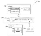
図1を参照すると、仮想機械配管システムの共同開発を容易にする例示的なシステム100が示されている。システム100は少なくとも1つのプロセッサ102を含むことができ、このプロセッサは、本明細書で説明する種々の特徴を実施するために、メモリ106から1つまたは複数のアプリケーションソフトウェアコンポーネント104を実行するように、コンフィギュレーションされている。共同開発を実施するアプリケーションソフトウェアコンポーネント104は、1つまたは複数の要素から成る1つの独立したアプリケーションに相応するものとすることができ、かつ/または他の機能を実行するソフトウェアに統合/含めることができる。
With reference to FIG. 1, illustrated is an
たとえば、本明細書で説明する特徴を実施する上述のアプリケーションソフトウェアコンポーネント104を、CAD/CAM/CAE(コンピュータ支援設計/コンピュータ支援製造/コンピュータ支援工学)ソフトウェア、および/またはPLMソフトウェアならびに建築用ソフトウェア、および/または機械配管システムの開発に用いることのできる他のタイプのソフトウェアに相応させることができ、またはそれらに組み込むことができる。仮想機械配管システムの共同開発のために、本明細書で説明する機能の少なくともいくつかを含むように適合可能なPLMソフトウェアおよび/またはCAD/CAM/CAEソフトウェアの一例として、Siemens Product Lifecycle Management Software Inc. (Plano, Texas)から市販されているTeamcenter PLMおよび/またはNX suites of applicationsが挙げられる。
For example, the
既述のシステムは、少なくとも1つの(表示画面などのような)ディスプレイデバイス108と、少なくとも1つの入力デバイス110とを含むことができる。たとえばプロセッサは、PC、ノートブックコンピュータ、ワークステーション、サーバ、タブレット、モバイルフォン、または他の任意のタイプのコンピュータシステムの一部分として含まれるものとすることができる。ディスプレイデバイスはたとえば、LCDディスプレイ、モニタおよび/またはプロジェクタを含むことができる。入力デバイスはたとえば、マウス、ポインタ、タッチスクリーン、タッチパッド、ドローイングタブレット、トラックボール、ボタン、キーパッド、キーボード、ゲームコントローラ、カメラ、ジェスチャ動作をキャプチャするモーションセンシングデバイス、または本明細書書で説明する入力を供給可能な他の任意のタイプの入力デバイスを含むことができる。同様にタブレットなどのデバイスのためにもプロセッサ102を、入力デバイスとディスプレイデバイスの双方として用いられるタッチスクリーンを含むハウジング内に組み込むことができる。さらに、(ゲームコントローラなどのような)いくつかの入力デバイスは、異なる複数のタイプの入力デバイス(アナログスティック、dパッドおよびボタン)を含むことができる、という点も理解されたい。
The described system can include at least one display device 108 (such as a display screen) and at least one
同様にここで述べておくと、本明細書で説明するプロセッサを、本明細書で説明するディスプレイデバイスおよび入力デバイスとは離れた場所にあるサーバ内に配置してもよい。かかる例によれば、既述のディスプレイデバイスおよび入力デバイスを、クライアントデバイス内に含めてもよく、このクライアントデバイスは、(インターネットを含むことのできる)有線または無線のネットワークを介してサーバ(および/またはサーバ上で実行される仮想マシン)と通信する。いくつかの実施形態によれば、かかるクライアントデバイスはたとえば、入力デバイスからサーバへ入力を送信し、かつサーバから視覚情報を受信してディスプレイデバイスにより表示する目的で、リモートデスクトップアプリケーションを実行することができ、またはサーバと共にリモートデスクトッププロトコルを実行することができる。かかるリモートデスクトッププロトコルの例として、Teradici社のPCoIP、Microsoft社のRDPおよびRFBプロトコルが挙げられる。かかる例によれば、本明細書で説明するプロセッサを、サーバの物理的プロセッサにおいて実行される仮想マシンの仮想プロセッサに対応させることができる。 Similarly, as noted herein, the processor described herein may be located in a server that is remote from the display and input devices described herein. According to such an example, the aforementioned display device and input device may be included within a client device, which client device (and / or via a wired or wireless network (which may include the Internet)). Or a virtual machine running on the server). According to some embodiments, such a client device may execute a remote desktop application, for example, for the purpose of sending input from the input device to the server and receiving visual information from the server and displaying it on the display device. Or a remote desktop protocol can be run with the server. Examples of such remote desktop protocols include Teradici's PCoIP, Microsoft's RDP and RFB protocols. According to such an example, the processor described in this specification can correspond to a virtual processor of a virtual machine executed on a physical processor of a server.
いくつかの例示的な実施形態によれば、システムはさらにデータストア112を含むことができる。データストアは、(1つの構造の要素および各要素間の関係を指定する)オブジェクトデータ114、CADデータ116(たとえば要素の構造の3Dの物理的形状およびコンフィギュレーションを指定するCADファイルなど)、および機械配管システムの開発に役立つ可能性のある他の任意のデータを含むことができる。本明細書で説明する1つまたは複数のデータストアとして使用することのできるデータベースの例として、Oracle, Microsoft SQL Serverまたはデータレコードを格納するように動作する他の任意のタイプのデータストアが挙げられる。 According to some exemplary embodiments, the system may further include a data store 112. The data store includes object data 114 (which specifies the elements of one structure and the relationship between each element), CAD data 116 (eg, a CAD file that specifies the 3D physical shape and configuration of the structure of the elements), and Any other data that may be useful in the development of a mechanical piping system may be included. Examples of databases that can be used as one or more of the data stores described herein include Oracle, Microsoft SQL Server, or any other type of data store that operates to store data records. .
これに加え、既述のアプリケーションソフトウェアコンポーネント104は、ディスプレイデバイス108を介して、インタラクティブなグラフィカルユーザインタフェース(GUI)118を生成することができる。ユーザはGUIを用いて、少なくとも1つの配管経路120およびこの配管経路を有する要素を含む機械配管システムの三次元(3D)表現を生成、変更および表示することができる。さらにGUIを用いて、配管経路(ならびに他の構造)を含む機械配管システムのためのオブジェクトデータ114およびCADデータ116に対応するデータを、データストア112に格納することができ、かつデータストア112から取り出すことができる。たとえば既述のGUI 118は、データストアに格納されたオブジェクトおよびCADデータを介して機械配管システムを設計および閲覧しながら使用するための、CADソフトウェアのGUIを含むことができる。
In addition, the described
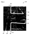
図2には、ある船舶の船体に組み込まれている例示的な機械配管システム200のイメージが描かれている。かかる機械配管システムは、複数のパイプライン配管経路202,204,206,208を含むことができ、これらは(タンクやエンジンなどのような)設備214を接続するパイプ210,212またはダクトといった要素を通して、流体(たとえば水、油、燃料、ガスおよび他の化学物質)の流れを生じさせる。かかるパイプライン配管経路には、継手216(たとえばフランジ/エルボ/T字管)およびそれらのパイプラインの構造において用いられるインライン設備(たとえばバルブ/ポンプ)などのような要素も含むことができる。これらに加えパイプライン配管経路には、センサ(たとえば温度計/圧力計)および様々な場所でパイプラインに取り付けまたは適用可能なインシュレーションを含むことができる。さらに配管経路周囲の周辺環境スペースは、壁、床218、手すり220、支持部材、および他の構造を含むことができる。海洋、航空宇宙、プラントおよびエネルギーといったいくつかの産業においては、配管システムの設計が、新たな船舶、ロケット、ビルディング、化学プラントまたは原子力エネルギープラントのための設計活動全体のうち、かなりの割合を占める可能性がある。
FIG. 2 depicts an image of an exemplary
図3には、単一のパイプライン配管経路324を有する機械配管システム326の物理的構造の3D表現300が示されている。この3D表現300を、既述の少なくとも1つのプロセッサにおいて実行されるCADソフトウェアを含むアプリケーションソフトウェアコンポーネントを介して、ディスプレイデバイスにより出力することができる。この例の場合、配管経路には、ポンプ302およびタンク322などのような装備品に相応する2つの終端要素が含まれている。これら2つの終端要素の間に複数の中間要素が存在しており、これらは2つの終端要素間で流体を連通させることができる。この例によれば中間要素に含まれるのは、第1のフランジ304、第1のパイプ306、第1のエルボ308、第2のパイプ310、第2のフランジ312、第3のフランジ314、第3のパイプ316、第2のエルボ318、さらに複数の付加的な要素320である。
In FIG. 3, a
かかる構造を、配管アセンブリCADファイルを用いて管理することができる。図4には、図3に示したパイプライン配管経路324のかかるCADファイル400の概略的表現が示されている。単一のCADファイルは個々のCADデータ402〜422を含むことができ、これらのデータによって、図3に示した機械配管経路324の個々の物理的要素302〜322各々について、3Dビジュアル表現がそれぞれ定義される。この例では、配管アセンブリCADファイル400は、パイプラインの形状を具体的に定義する別個のワイヤフレームパス424を含むことができる。CADファイル400内のパイプラインの3D要素の個々のCADデータ402〜422を、このファイル内でワイヤフレームパスに沿ったポジションに関連づけることができる。したがってCADソフトウェアは、ファイルをオープンしてパイプライン配管アセンブリのレンダリングを生成することができ、その際、ワイヤフレームパスと関連づけられた3D要素各々がレンダリングされ、レンダリングされた要素がファイル内で指定されたとおりにワイヤフレームに沿って特定のポジションに配置される。
Such a structure can be managed using a piping assembly CAD file. FIG. 4 shows a schematic representation of such a
ここで理解されたいのは、かかる配管アセンブリの改訂中、ワイヤフレームパスを変更する目的で、配管アセンブリCADファイル400をロックしなければならない場合もあり、そうなった場合には他のユーザに対しアクセスが阻止される、ということである。それぞれ異なるアプリケーション(たとえばそれぞれ異なる船舶設計)のために、(たとえば第2のタンクを含む)変更されたパスを有する機械配管システムの第2のコンフィギュレーションが必要とされるならば、配管アセンブリCADファイルの改訂バージョンを生成することができ、これには変更されたパスの付加的な要素および/または変更された要素が含まれる。かかる改訂CADファイルは、変更されていない要素すべての複製を含むこともできる(配管システムに対し若干の改訂がなされただけであれば、それらが要素の大半となり得る)。
It should be understood that during such a pipe assembly revision, the pipe
複数のユーザが、かかる機械配管システムのそれぞれ異なる部位を改訂する必要があるときに、フレキシビリティを高める目的で、図1に示されているように、データストア112に格納されている分散型配管パス122を生成および操作するように、1つの実施形態を構成することができる。このアプローチによれば、既述の配管アセンブリCADファイルの場合のように、制御要素において定義される明示的なワイヤフレーム配管パスは存在し得ない。その代わりに、分散型配管パス122は、データストア112に格納されたデータにおいて個々に相互にリンクされている要素自体のコンフィギュレーションに、(レンダリング時に)ダイナミックに基づく動的形状を有することができる。配管パスを定義するためのかかる分散型アプローチによって、複数の大規模な機械配管システムを同時に設計できるようになり、ユーザが配管パスの形状を明示的に管理しなくてもよくなる。むしろ、設計変更は要素自体に対して実施され、パスはそれらの要素から構成された結果として生じることになる。
In order to increase flexibility when multiple users need to revise different parts of such a machine piping system, distributed piping stored in data store 112 as shown in FIG. One embodiment can be configured to generate and manipulate the
たとえば図1を参照すると、システム100の少なくとも1つのプロセッサ102は、第1および第2のコンピュータシステム(たとえばワークステーション)それぞれに含まれている第1および第2のプロセッサを含むことができる。(たとえばCADソフトウェアを含む)アプリケーションソフトウェアコンポーネントの第1および第2のインスタンスを以下のように実行するように、これらのプロセッサ各々をコンフィギュレーションすることができる。すなわち、第1および第2のコンピュータシステムによってそれぞれ異なるユーザが同時に、配管経路における要素のそれぞれ異なるサブセットをロードして、これに設計変更を加え、分散型配管パスに対する相応の変更を同じデータストアに格納できるようにするのである。
For example, referring to FIG. 1, at least one
1つの実施形態によれば、分散型配管パスを定義する個々の要素を、(PLMシステムのリレーショナルデータベースなどのような)データストア112内に個々のビジネスオブジェクトとして格納されたコンポーネントおよびコンポーネントに対する改訂に対応させることができる。要素各々は、それら固有の独立したライフサイクルを有することができ、部品表においてコンフィギュレーション可能である。本明細書で説明する配管システムのビジネスオブジェクトを管理するために使用可能なPLMフレームワークの例として、2013年9月12日公開の米国特出願公開第2013238508号明細書(US Publication No. 2013238508)を挙げることができる。ここでこの文献を参照したことにより、その開示内容全体が本明細書に取り込まれたものとする。 According to one embodiment, individual elements that define a distributed piping path can be revised to components and components stored as individual business objects in a data store 112 (such as a relational database in a PLM system). Can be matched. Each element can have its own independent life cycle and is configurable in the bill of materials. As an example of a PLM framework that can be used to manage the piping system business objects described herein, US Publication No. 2013238508, published September 12, 2013 (US Publication No. 2013238508). Can be mentioned. By referring to this document here, it is assumed that the entire disclosure is incorporated herein.
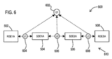
いくつかの例示的な実施形態によれば、分散型配管パスをデータとしてデータストアに格納するために、データストアは(テーブルなどのような)複数のデータ構造を含むことができ、それら複数のデータ構造をひとまとめにして使用することにより、分散型配管パスを生成(および決定)するために使用すべき関係を格納することができる。図5には、例示的な配管経路500の概略的表現が示されており、これを既述の分散型配管パスによるデータとして表すことができる。この例の場合、配管経路500は、2つの終端要素502、508(RDE1/A,RDE2/A)と、これらの終端要素に接続されかつ相互に接続された2つの中間要素504,506(SDE1/A,SDE2/A)とを含んでいる。この例によれば、2つの終端要素を(既述のポンプやタンクなどの)装備に相応するものとすることができ、中間要素をフランジ、パイプまたは他のパイプライン部品に相応するものとすることができる。
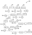
According to some exemplary embodiments, in order to store a distributed piping path as data in a data store, the data store can include multiple data structures (such as tables). By using the data structure together, the relationships to be used to create (and determine) the distributed piping path can be stored. FIG. 5 shows a schematic representation of an
図6は、図5に示した配管経路500のための分散型配管パス600の一例を示す。この図には、データストアに格納された1つまたは複数のテーブルおよびテーブルレコードにより表すことのできる上位レベルのオブジェクトセット610によって、分散型配管パスが示されている。この例によれば、分散型配管パスの終端要素502,508(RDE1/A,RDE2/A)を指定する配管パスグループ602(G1)を格納するように、データストアをコンフィギュレーションすることができる。これに加え、分散型配管パスに含めるべき要素ペア間の関連づけを定義する配管パスリンク604,606,608(L1,L2,L3)を格納するように、データストアをコンフィギュレーションすることができる。かかる要素ペアは、終端要素502,508(RDE1/A,RDE2/A)と、1つまたは複数の(一般的にはもっと多くの)中間要素504,506(SDE1/A,SED2/A)とを含むことができる。リンク604,606,608(L1,L2,L3)各々は、これらが関連づけられた特定の配管パスグループ602(G1)を指定することもできる。
FIG. 6 shows an example of a distributed
したがって、このような既述のデータから分散型配管パスを再生成するために、所望の機械配管経路500の配管パスグループ602(G1)およびこの配管パスグループに関連づけられた配管パスリンク604,606,608(L1,L2,L3)を、データストアから取り出すように、(CADソフトウェアなどのような)アプリケーションソフトウェアコンポーネントをコンフィギュレーションすることができる。アプリケーションソフトウェアは、取り出されたこのデータを使用して、分散型配管パスの終端要素502,508(RDE1/A,RDE2/A)と、中間要素504,506(SDE1/A,SDE2/A)とを決定することができる。
Therefore, in order to regenerate the distributed piping path from the above described data, the piping path group 602 (G1) of the desired
決定された要素各々についてアプリケーションソフトウェアコンポーネントは、これらの要素の物理的構造の3D表現を生成するために使用可能な相応のCADデータ(CADファイルなど)をデータストアから取り出すように、動作することもできる。いくつかの例示的な実施形態によればデータストアは、CADファイルなどのCADデータをデータストアのデータレコードに格納することができる。ただし他の実施形態において、データストアを以下のような分散型システムに対応させることができる、ということを理解されたい。すなわちこの分散型システムは、リレーショナルデータベースとファイルサーバとを含み、この場合、リレーショナルデータベースに格納されたCADデータが、ファイルサーバ(または他のタイプのデータストア)から取り出す特定のCADファイルを指定するのである。さらにいくつかの例示的な実施形態によれば、配管経路の個々の要素各々についてCADデータを別個のCADファイルおよび/またはデータレコードに配置できる、ということを理解されたい。しかしながら他のコンフィギュレーションによれば、それぞれ異なる要素のCADデータを、同じCADファイルおよび/またはCADデータレコードから別個に取り出すことができる。 For each determined element, the application software component may also operate to retrieve corresponding CAD data (such as a CAD file) that can be used to generate a 3D representation of the physical structure of these elements from the data store. it can. According to some exemplary embodiments, the data store may store CAD data, such as CAD files, in data records of the data store. However, it should be understood that in other embodiments, the data store can correspond to a distributed system such as: That is, the distributed system includes a relational database and a file server, in which case the CAD data stored in the relational database specifies a particular CAD file to be retrieved from the file server (or other type of data store). is there. It should be further understood that according to some exemplary embodiments, the CAD data can be placed in a separate CAD file and / or data record for each individual element of the piping path. However, according to other configurations, CAD data for different elements can be retrieved separately from the same CAD file and / or CAD data record.
これに加え配管パスリンクは、指定された要素ペアのCADデータ中、いずれのオブジェクト(たとえば終端、ポート、接続ポイント)を互いに接続すべきであるのかを指定する情報(たとえばハンドルデータ)を含むことができる。例示的なアプリケーションソフトウェアコンポーネントは、要素のCADデータおよび配管パスリンクにおけるデータに応答して、機械配管経路500の3D表現をディスプレイデバイスを介してダイナミックにレンダリングすることができる。ここでアプリケーションソフトウェアは、配管経路の仮想3D表現をダイナミックに組み立てるために、配管パスリンクと、(要素のいずれの部分を互いに接続するのかを指定する)ハンドルデータと、要素のCADデータ中で定義された要素のコンフィギュレーション/形状とに基づき、いずれの要素をロードし、いずれの場所にそれらの要素を配置し、いずれの場所で要素ペアを接続するのか、を決定する。配管パスリンクがPLMシステムのデータストアに格納されている例示的な実施形態によれば、かかる配管パスリンクを、(たとえばCADソフトウェアを含むことができる)既述のアプリケーションソフトウェアコンポーネントによって管理されるPLMシステムに格納されたオブジェクトに相応するものとすることができる。
In addition to this, the pipe path link includes information (for example, handle data) that specifies which objects (for example, termination, port, connection point) should be connected to each other in the CAD data of the specified element pair. Can do. The example application software component can dynamically render a 3D representation of the
図7には、図5に示した機械配管経路500の分散型配管パス600を格納する目的で、PLMシステムのデータストア内の複数のテーブルに格納可能なデータレコード700の一部分のセットが示されている。この例によれば、既述の配管パスグループ602(G1)を接続グループレコード702に格納することができ、この接続グループレコード702によって、終端要素のデータストアに格納されたコンポーネントレコード704,706に対する特定の参照を介して、2つの既述の終端要素(RDE1/A,RDE2/A)が指定される。かかるコンポーネントレコードは、要素の物理的構造の3D表現のレンダリングに用いるために、特定のCADデータを(データストア内の他のレコードに対する関連づけを介して)参照することができる。
FIG. 7 shows a partial set of
この例の場合にも、既述の配管パスリンク604,606,608(L1,L2,L3)を、複数の関連づけられたリンクレコードの組み合わせとして、データストアに格納することができる。かかる関連づけられたリンクレコードは、グループレコード702を参照するグループリンクレコード708,710,712を含むことができる。さらにかかる関連づけられたリンクレコードは、リンク要素レコード714〜724(リンクL1,L2,L3ごとに2つ)を含むこともでき、これらのリンク要素レコード714〜724は、データストアに格納された終端コンポーネント(RDE1/A,RDE2/A)のコンポーネントレコード704,706に対する特定の参照と、中間コンポーネント(SDE1/A,SDE2/A)のコンポーネント参照726,728とを介して、分散型配管パスの要素すべてをそれぞれ指定する。
Also in this example, the above-described piping path links 604, 606, 608 (L1, L2, L3) can be stored in the data store as a combination of a plurality of linked link records. Such associated link records can include group link records 708, 710, 712 that reference the
分散型配管パスの要素が、アプリケーションソフトウェアコンポーネントによって(たとえばCADソフトウェアなどによって)コンフィギュレーションされてロードされる場合には、配管パスリンクのハンドルデータを処理して、ランタイム3Dジオメトリ制約ネットワークをメモリに生成することができる。このネットワークによってアプリケーションソフトウェアコンポーネントは、(GUIを介した)要素とのユーザインタラクションを、形状およびポジションの変化に変換することができ、さらに各要素間の配管パスリンクに対する変更を捕捉することもできる。 If distributed pipe path elements are configured and loaded by application software components (eg, by CAD software), handle pipe path link handle data to generate a runtime 3D geometry constraint network in memory can do. This network allows application software components to translate user interaction with elements (via the GUI) into changes in shape and position, and can also capture changes to the piping path link between each element.
生成/消去/更新されたすべての配管パスリンクおよびCADデータを、アプリケーションソフトウェアコンポーネントによってPLMシステムのデータストアに戻して存続させることができる(すなわち格納することができる)。次いでユーザは、分散型配管パスの接続された複数の要素から成るそのつど一時的な任意の集合(たとえばサブセット)を、アプリケーションソフトウェアコンポーネントにロードすることができ、設計変更を加えることができる。それらの要素は、上述のようにデータストア内に分散されているので、アプリケーションソフトウェアコンポーネントは、分散型配管パス全体ではなくその一部の部位のみをロードして操作することができる。 All piping path links and CAD data created / deleted / updated can be persisted (ie, stored) back to the PLM system data store by the application software component. The user can then load any temporary set (eg, a subset) of connected multiple elements of the distributed piping path into the application software component and make design changes. Since these elements are distributed in the data store as described above, the application software component can load and manipulate only a portion of the distributed piping path rather than the entire distributed piping path.
ただしここで理解されたいのは、分散型配管パスの一部の部位だけが1つまたは複数の設計変更を有する場合に、分散型配管パスのうちロードされていない他の部位に対し、かかる設計変更が影響を及ぼす可能性もあるし、または及ぼさない可能性もある、ということである。設計変更により分散型配管パスの他の部位に及ぼされた可能性のある影響を評価するために、配管パスリンクの例示的な実施形態は整合性データを含むことができる。たとえばアプリケーションソフトウェアコンポーネントを、データストア内の関連づけられたリンクレコードに(最終変更日時などのような)整合性データを格納するように、コンフィギュレーションすることができる。この場合、ロードされた要素のうち1つまたは複数の要素に対する何らかの設計変更によって、何らかの2つの要素間のリンクが無効とされ、したがって設計変更とロードされなかった要素との間の整合性について分散型配管パスの評価が必要とされるか否かを、上述の整合性データを使用して判定することができる。 However, it should be understood that if only some parts of a distributed piping path have one or more design changes, such a design may be made for other unloaded parts of the distributed piping path. The change may or may not have an effect. In order to assess the impact that a design change may have had on other parts of the distributed piping path, exemplary embodiments of the piping path link may include consistency data. For example, an application software component can be configured to store consistency data (such as the last modified date) in an associated link record in the data store. In this case, any design change to one or more of the loaded elements will invalidate the link between any two elements, thus distributing consistency between the design change and the unloaded element Whether the evaluation of the mold piping path is required can be determined using the consistency data described above.
以下でさらに詳しく述べるように、リンクにより指定された要素ペアのうちの一方が、アプリケーションソフトウェアコンポーネントよって改訂された場合には、配管パスリンクについてかかる整合性データが変化する可能性がある。配管パスリンクにおける整合性情報の比較によって、上述のアプリケーションソフトウェアコンポーネントは、以下のように動作することができる。すなわち、リンクおよび対応する要素のすべてが動作する機械配管構造を定義し続けている、ということを検証するために、分散型配管パスの再評価がいつ必要になり得るのかを決定し、定義し続けていないのであれば、いくつかの要素に加えられた変更に合わせて要素に対し付加的に改訂が必要になり得ることを、ユーザにフラグで通知するのである。 As described in more detail below, if one of the element pairs specified by the link is revised by the application software component, such consistency data may change for the piping path link. By comparing the consistency information in the piping path link, the application software component described above can operate as follows. That is, determine and define when a reassessment of the decentralized piping path may be required to verify that all of the links and corresponding elements continue to define working mechanical piping structures. If not, flag the user that additional revisions to the element may be required to accommodate changes made to some elements.
図8には、図3に示した機械配管システム326の改訂により生成可能な機械配管システム818の物理的構造の3D表現800が示されている。この第2の改訂はたとえば、配管システムが必要とされる周辺環境スペースの異なるバリエーションに対して、必要とされる可能性がある。たとえば図3に示した配管システム326を、第1のタイプの船舶の船体に関するものすることができる一方、図8に示した配管システム818を、第2のタイプの船舶のための、上述の船体の1つのバリエーションに関するものとすることができる。
FIG. 8 shows a
この改訂によれば、(図3に示した)単一のパイプライン配管経路324が、アプリケーションソフトウェアコンポーネントを介して、2つのパイプライン配管経路814,816を含むように変更されている。これら2つのパイプライン配管経路814,816は、ポンプ302の共通の終端要素から出発しているが、これらは分岐して2つの異なる終端要素のところに別々に延在し、これら2つの異なる終端要素は元の第1のタンク322および新たな第2のタンク812を個々に含んでいる。
According to this revision, a single pipeline piping path 324 (shown in FIG. 3) has been modified to include two
この改訂をアプリケーションソフトウェアコンポーネントによって達成する目的で、ユーザは、両方のバリエーションに適用可能な元の配管システム326のできるかぎり多くの部分を維持する、ということを選択できる。したがって両方の配管経路814,816は、ポンプ302と、第1のフランジ304から第2のフランジ314までの中間要素とを維持することができる。同様に元の第2のエルボ318、第1のタンク322および付加的な中間要素320も、新たな改訂において維持することができる。しかしながら第2の配管経路816に合わせるために、(図3に示した)元の第3のパイプ316を、(第2のタイプの船舶についてのみ)それよりも短い2つの新たな第7および第8のパイプ802,806およびそれらの間のT字管804から成るセットと置き換えることができる。次いで、第2の配管経路816をT字管804から継続させることができ、ユーザはアプリケーションソフトウェアコンポーネントを使用して、第9のパイプ808と複数の付加的な中間要素810と第2のタンク812とを追加することができる。
In order to achieve this revision by the application software component, the user can choose to maintain as much of the
この例によれば、ユーザが新たな配管システム818を生成するときに、アプリケーションソフトウェアコンポーネントは、第1および第2の経路814,816各々のための新たな分散型配管パスに対応する新たなデータオブジェクトおよび相応のデータレコードを、データストア内に生成するように動作可能である。かかる新たな分散型配管パスは、元の配管経路324から変更されないまま存続している配管パスリンクのデータオブジェクトを含むことができる。ただしかかる新たな分散型配管パスは、新たな中間要素802〜810と新たな終端要素812すべての接続に関する新たなリンク、ならびに古い中間要素(たとえば第3のフランジ314および第2のエルボ318)と新たな中間構造(第7および第8のパイプ802,806)との間の接続に関する新たなリンクを含むことになる。
According to this example, when the user creates a
図9には、データストアに格納可能なオブジェクトセットが示されており、これは以下のような例示的手法を示している。すなわちこれによれば、図3に示した元の配管システム324の単一のパイプライン配管経路324と、図8に示した新たな配管システム818の2つのパイプライン配管経路814,816の双方を表現できるように、分散型配管パス900を組織化することができる。
FIG. 9 shows a set of objects that can be stored in a data store, which illustrates an exemplary approach as follows. That is, according to this, both the single
この例の場合、データストアを、図3および図8に示された要素を表現する各オブジェクト間の配管パスリンク902〜926(L1〜L19)を格納するためのものとすることができる。また、データストアを、図3および図8に示したパイプライン配管経路324,814,816に対応する3つの配管パスグループ928,930,932(G1,G2,G3)を格納するためのものとすることができる。リンク902〜912(L1〜L6)は3つの経路すべてに共通であり、したがってこれらのリンクを、データストアに格納されるためのものである3つのグループ928,930,932(G1,G2,G3)すべてに関連づけることができる。リンク918,920(L15,L16)は、(図8に示した)2つの新しい方の経路814,816に共通であり、データストア内においてグループ930,932(G2,G3)のみに関連づけることができる。ただしリンク914,916(L7,L8)はたとえば、第1の配管パスグループ928(G1)のみに関連づけることができる。同様にリンク922,924(L17,L18)は、第2の配管パスグループ930(G2)のみに関連づけることができる。さらに同様にリンク926(L19)は、第3の配管パスグループ932(G3)のみに関連づけることができる。
In this example, the data store may be for storing piping path links 902-926 (L1-L19) between each object representing the elements shown in FIGS. The data store is for storing three piping
(図8に示した)配管システム818のために新たなデータを追加することに伴い、第1のタイプの船舶にとっては有効であっても、第2のタイプの船舶にとっては有効でないというように、(図3に示した)元の配管システム326の「有効性」が縮小される可能性がある。その結果、第3のパイプ316などのような要素のためのデータは、第1のタイプの船舶にしか適用できない可能性がある一方、新たな配管システムの要素のために追加されたデータ(たとえば第2のタンク812)は、第2のタイプの船舶のためにしか適用できない可能性がある。同様に、両方の設計は多くの要素と配管パスリンクを共有しているにもかかわらず、第2の配管システム812の追加によっても、元の配管システム326を再確認する必要がない場合もある。このような結果が生じる理由は、元の要素のいずれも改訂されてはおらず、元の配管システム326のための分散型配管パスの配管パスリンクのいずれも無効にはならず、またはデータストアに対する新たな配管システム812の追加と不整合になることがないからである。
As new data is added for the piping system 818 (shown in FIG. 8), it is valid for the first type of ship, but not for the second type of ship. , The “effectiveness” of the original piping system 326 (shown in FIG. 3) may be reduced. As a result, data for elements such as the
オブジェクトをデータストアに格納するためのこの例示的なフレームワークは、高水準の同時設計活動のサポートすることができる。たとえば船舶などのような大規模な製品の場合、配管システムはその全長にわたり広がっている可能性がある。この例示的なフレームワークによれば、複数のユーザ(たとえば設計エンジニア)が互いに干渉し合うことなく同時に3D設計に取り組むことができる。さらにこの例示的なフレームワークによれば、ある1人のユーザは、多数の設計バリエーション間で共有されている要素をロードする必要なく、ある1つの特定のバリエーションに固有の設計部位に取り組むこともできる。 This exemplary framework for storing objects in a data store can support high-level concurrent design activities. For large products such as ships, for example, the piping system may extend over its entire length. This exemplary framework allows multiple users (eg, design engineers) to work on 3D design at the same time without interfering with each other. In addition, the exemplary framework also allows a single user to work on a design site that is specific to one particular variation without having to load elements that are shared between multiple design variations. it can.
これらの特徴を実施するため、例示的なアプリケーションソフトウェアコンポーネントによってシステムの一部の部位を「ゾーン」によって、またはサブシステムによって、種々のユーザに対して分散させることができ、これによって複数のユーザが設計中の配管パスの一部分に含まれるべき要素を細分化できるようになる。たとえば、図3に示した既述の配管経路324を、第1の船体設計に関連づけることができる一方、図8に示した第2および第3の配管経路814,816を、第2の船体設計に関連づけることができる。この例示的なフレームワークによって、それぞれ異なるユーザが、第2の船体の第2および第3の配管経路に関連づけられた種々の要素をロードすることができ、その際に第3のユーザが第1の船体と第2の船体の双方に共通する要素をロードおよび改訂する能力が排除されることがない。かかる特徴によって、データ管理および設計変更の検証にかかるコストを低減することができ、したがって生産性が高まり、かつ製品開発プロセスのコスト全体を低減することができる。
To implement these features, exemplary application software components allow parts of the system to be distributed to various users by “zones” or by subsystems, which allows multiple users to It becomes possible to subdivide the elements that should be included in a part of the piping path under design. For example, the previously described
1つの例示的な実施形態によれば、既述のアプリケーションソフトウェアコンポーネントを、ユーザがGUI(たとえばCADソフトウェアのGUIなど)を介して、設計中のパイプライン配管経路に関してデータストアに格納された分散型配管パスを生成および変更できるように、コンフィギュレーションすることができる。かかるソフトウェアによってユーザは、配管経路について名称および説明を規定することができ、さらにどの終端要素が進路の境界を成すのかを定義することができる。これに加えソフトウェアによってユーザは、データストアに格納されたCADデータに基づき画面を通して、各終端要素間に3D表現を有する中間要素をグラフィックで挿入および/または描画することができる。図3および図8には、設計中の配管経路の要素について表示可能なかかる3D表現の例示的な表示が描かれている。同様にこのソフトウェアは、終端要素と中間要素の選択および配置に応答して、データストアにデータレコードとして格納されるオブジェクトとして、既述の配管パスグループおよびリンクを生成することもできる。 According to one exemplary embodiment, the described application software components are distributed in a data store with respect to the pipeline piping path being designed by the user via a GUI (e.g., a CAD software GUI). It can be configured so that piping paths can be created and modified. Such software allows the user to define a name and description for the piping path, and further define which termination elements bound the path. In addition, the software allows the user to graphically insert and / or render intermediate elements having a 3D representation between each end element through the screen based on CAD data stored in the data store. FIGS. 3 and 8 depict exemplary displays of such 3D representations that can be displayed for elements of the piping path under design. Similarly, in response to selection and placement of termination and intermediate elements, the software can generate the previously described piping path groups and links as objects that are stored as data records in the data store.
以降の時点で、アプリケーションソフトウェアコンポーネントによってユーザは、配管パスの要素のすべてまたは一部分をロードすることができ、このケースではアプリケーションソフトウェアコンポーネントは、データストア内のデータに応答して、画面を介して配管パスの要素の3D表現を再生成することができる。アプリケーションソフトウェアコンポーネントによってユーザはさらに、いくつかの要素の外観たとえばそれらのサイズや形状などを変更することができ、それを配管パスの改訂バージョンとしてデータストアに戻して保存することができる。かかる改訂が生成された場合、アプリケーションソフトウェアコンポーネントは以下のように動作することができる。すなわち、それらの要素に対する改訂に関して新たなオブジェクトを生成してデータストアに格納し、さらに配管パスの以前のバージョンから変更されていない要素のいずれかに戻るように、改訂された新たな要素を接続する新たな配管パスリンクを生成するのである。 At a later point, the application software component allows the user to load all or part of the elements of the piping path, in which case the application software component responds to the data in the data store and pipes through the screen. A 3D representation of the elements of the path can be regenerated. The application software component also allows the user to change the appearance of some elements, such as their size and shape, and return them to the data store as a revised version of the piping path. If such a revision is generated, the application software component can operate as follows. That is, create new objects for revisions to those elements, store them in the data store, and connect the revised new elements back to one of the elements that has not changed from the previous version of the piping path A new pipe path link is generated.
ただし既述のようにユーザは、複数の要素から成る1つのサブセットだけを配管パスの元のバージョンからロードして変更する、ということを選択してもよい。ロードされたかかる要素に対する改訂は、ロードされていない配管パスの要素の外観に影響を及ぼすかもしれないし、または及ぼさないかもしれない。図10〜図12に示されている例示的なプロセスにおいて、かかる改訂を既述のアプリケーションソフトウェアコンポーネントによって処理することができる。 However, as described above, the user may choose to load and modify only one subset of multiple elements from the original version of the piping path. Revisions for such loaded elements may or may not affect the appearance of elements in the unloaded piping path. In the exemplary process illustrated in FIGS. 10-12, such revisions can be processed by the application software components described above.
たとえば図10には、図6に示した分散型配管パス600のオブジェクトに対応する上位レベルのオブジェクトセット1000が示されている。この例によればユーザは、アプリケーションソフトウェアコンポーネントを使用して、終端要素502(RDE1/A)のみをロードし、この要素に対し改訂を加えて、改訂された終端要素1002(RDE1/B)を生成する、ということを選択できる。この図の場合、実線のブロックはロードされた要素を表す一方、破線のブロックはロードされていない要素を示す。第1の中間要素504(SDE1/A)はロードされていないので、第1の配管パスリンク604(L1)は、改訂された第1の中間要素1002(SDE1/B)と整合しないおそれのある接続を、または問題を引き起こすおそれのある接続を、表す可能性がある。たとえば、第1の中間要素が改訂された終端要素と物理的に接続される個所であるポートの一部分が動かされてしまった可能性があり、したがって中間要素の目下の形状および/または長さであると、改訂された第1の終端要素と第2の中間要素506(SDE2/A)の双方に接続できない可能性がある。
For example, FIG. 10 shows an upper-level object set 1000 corresponding to the objects of the distributed
第1のリンク604(L1)が有効である(すなわち接続された要素ペア間で整合している)か否かを検証するためには、改訂された第1の終端要素1002(RDE1/B)と、第1の中間要素504(SDE1/A)の両方とも、ユーザがアプリケーションソフトウェアコンポーネント(たとえばCADソフトウェア)にロードすることが必要となる可能性がある。これが実施されたならば、ソフトウェアコンポーネントは、改訂された第1の終端要素と第1の中間要素の双方に関連づけられたリンクについて最終変更日時を比較するように動作可能である。この例の場合には、改訂が加えられたときに第1の終端要素だけしかロードされなかったので、改訂された第1の終端要素に関連づけられた第1のリンクの最終変更日時は、第1の中間要素に関連づけられた第1のリンクの最終変更日時よりも新しい、ということになる。アプリケーションソフトウェアコンポーネントは、より新しい日時を検出し、改訂された第1の終端要素と第1の中間要素との間の接続を有効にしなければならない可能性がある、という何らかの視覚的インジケータをGUIに供給させるように、動作することができる。 In order to verify whether the first link 604 (L1) is valid (ie, consistent between connected element pairs), the revised first termination element 1002 (RDE1 / B) And both of the first intermediate elements 504 (SDE1 / A) may require the user to load into an application software component (eg, CAD software). Once this is done, the software component is operable to compare the last modified date and time for links associated with both the revised first terminal element and the first intermediate element. In this example, only the first end element was loaded when the revision was made, so the last modified date of the first link associated with the revised first end element is That is, it is newer than the last modification date and time of the first link associated with one intermediate element. The application software component detects some new date and time and gives the GUI some visual indicator that the connection between the revised first end element and the first intermediate element may have to be valid. Can be operated to supply.
図11には、第1の改訂された終端要素1002(RDE1/B)と中間要素504(SDE1/A)の双方が、アプリケーションソフトウェアコンポーネントにロードされた後の、分散型配管パスのオブジェクトの例1100が示されている。ただしここでは、第2の中間要素506(SDE2A)はロードされていないままである。この例によればユーザは、改訂された第1の終端要素と第1の中間要素との間のリンクが良好である、ということを検証することができ、第1のリンク604(L1)を更新させることができ、その結果、それらの最終日時が等しくなり、それらの要素間で整合性のある良好な接続を表すことになる。 FIG. 11 shows an example of a distributed piping path object after both the first revised termination element 1002 (RDE1 / B) and intermediate element 504 (SDE1 / A) have been loaded into the application software component. 1100 is shown. Here, however, the second intermediate element 506 (SDE2A) remains unloaded. According to this example, the user can verify that the link between the revised first terminal element and the first intermediate element is good, and the first link 604 (L1) Can be updated so that their final date and time are equal and represent a good connection with consistency between those elements.
同様にこの例によればユーザは、第1の中間要素504(SDE1/A)を改訂し(たとえばそれが長くなるようにし)、それにより改訂された第1の中間要素1102(SDE1/B)が生成される、ということも選択できる。この場合、改訂された第1の終端要素1002(RDE1/B)と、改訂された第1の中間要素(SDE1/B)の両方がロードされるので、ユーザはこれらの要素間の接続を検証することができ、第1のリンク604(L1)の最終変更日時が一致して、良好な接続を表すことになる。ただし、第2の中間要素506(SDE2/A)はロードされないので、第2のリンク606(L2)は有効であるかもしれないし、有効でないかもしれない。よって、第2のリンクを有効にするために、ユーザは第2の中間要素506(SDE2/A)をロードすることができる。 Similarly, according to this example, the user may revise the first intermediate element 504 (SDE1 / A) (eg, to make it longer), thereby revising the first intermediate element 1102 (SDE1 / B). Can also be selected. In this case, both the revised first termination element 1002 (RDE1 / B) and the revised first intermediate element (SDE1 / B) are loaded, so the user verifies the connection between these elements. The last change date and time of the first link 604 (L1) coincides and represents a good connection. However, since the second intermediate element 506 (SDE2 / A) is not loaded, the second link 606 (L2) may or may not be valid. Thus, to enable the second link, the user can load the second intermediate element 506 (SDE2 / A).
図12には、改訂された第1の終端要素1002(RDE1/B)と、改訂された第1の中間要素1102(SDE1/B)と、第2の中間要素506(SDE2/A)が、アプリケーションソフトウェアコンポーネントにロードされた後の、分散型配管パスのオブジェクトの例1200が示されている。この例によればユーザは、改訂された第1の中間要素と第2の中間要素との間のリンクが整合性について問題を有している(たとえば整列されていない)、という判定を下すことができる。このためユーザは、第2の中間要素を改訂して、改訂された第1の中間要素1102(SDE1/B)と両立性のある改訂された第2の中間要素1202(SDE2/B)を生成する、ということを選択できる。アプリケーションソフトウェアコンポーネントの1つの例示的な実施形態は、(最終変更日時の不一致を介して)第2のリンク606(L2)が良好でないことを検出し、かつ(第2のリンクの一部である)第2の中間要素が改訂されたことを検出するように、動作可能である。この判定に応答して、改訂された第1の中間要素1102(SDE1/B)と改訂された第2の中間要素1202(SDE2/B)との間に、新たな第4のリンク1204(L4)を自動的に生成するように、アプリケーションソフトウェアコンポーネントをコンフィギュレーションすることができる。 FIG. 12 shows a revised first termination element 1002 (RDE1 / B), a revised first intermediate element 1102 (SDE1 / B), and a second intermediate element 506 (SDE2 / A). An example distributed piping path object 1200 after being loaded into an application software component is shown. According to this example, the user makes a determination that the link between the revised first intermediate element and the second intermediate element has a problem with consistency (eg, not aligned). Can do. Thus, the user revises the second intermediate element to produce a revised second intermediate element 1202 (SDE2 / B) that is compatible with the revised first intermediate element 1102 (SDE1 / B). Can be selected. One exemplary embodiment of the application software component detects that the second link 606 (L2) is not good (via a last modified date mismatch) and is part of the second link. ) It is operable to detect that the second intermediate element has been revised. In response to this determination, a new fourth link 1204 (L4) between the revised first intermediate element 1102 (SDE1 / B) and the revised second intermediate element 1202 (SDE2 / B). ) Can be configured to automatically generate).
なお、アプリケーションソフトウェアコンポーネントによってユーザは1つの配管パスを、1つまたは複数の改訂された要素を含む改訂された新たな配管パスとして保存できる、ということを理解されたい。この状況において、改訂された何らかの新たな要素と、改訂されていない(元の配管パスにも存続している)古い要素との間に、新たな配管パスリンクを自動的に生成するように、アプリケーションソフトウェアコンポーネントをコンフィギュレーション可能である。 It should be understood that the application software component allows a user to save a piping path as a revised new piping path that includes one or more revised elements. In this situation, to automatically generate a new pipe path link between any new element that has been revised and an old element that has not been revised (which still exists in the original pipe path) Application software components can be configured.
大規模なプロジェクトであると、それぞれ異なるユーザが1つの構造のそれぞれ異なる設計範囲の設計を担当する場合もある、ということを理解されたい。たとえば設計マネージャは、上位レベルにおいて、機械配管経路の汎用的なコンポーネントの論理的表現に対応する論理的設計を指定することができ、論理的設計の実装に必要とされる固有の3D構造の設計に関する詳細を、他のユーザに任せることができる。既述のアプリケーションソフトウェアコンポーネントの1つの例示的な実施形態は、以下のようなコンポーネントを含むことができる。すなわちこのコンポーネントによってユーザは(入力デバイスによる入力を介して)、(論理的デザイナコンポーネントによる)論理的配管経路と、(3D CADソフトウェアコンポーネントによる)論理的経路のための3D機械設計の双方を、生成できるようになる。 It should be understood that in a large project, different users may be responsible for designing different design areas of a structure. For example, at a higher level, a design manager can specify a logical design that corresponds to a logical representation of a generic component of a machine piping path, and design a unique 3D structure required to implement the logical design. Details about can be left to other users. One exemplary embodiment of the aforementioned application software components may include the following components: That is, this component allows the user to generate both a logical piping path (via a logical designer component) and a 3D mechanical design for the logical path (via a 3D CAD software component) (via input via an input device). become able to.
図13には、GUIからの出力1300の一例が示されている。この出力は、アプリケーションソフトウェアコンポーネントにより生成可能であり、このアプリケーションソフトウェアコンポーネントを用いて生成された論理的配管設計1302に相応する。かかる論理的設計を、図3に示したパイプライン配管経路324に対応する論理的経路のためのものとすることができる。かかる論理的設計により、2Dシンボルおよびグラフィックスを介してたとえば、ポンプ1304などのような第1の装備、タンク1306などのような第2の装備、およびそれらの間の汎用的な接続1308(C1/A)に対する要求を、幅広く定義することができる。かかる論理的設計1302をデータストアに保存するように、アプリケーションソフトウェアコンポーネントをコンフィギュレーションすることができる。アプリケーションソフトウェアコンポーネントの一部分を介して物理的パイプライン配管経路324を設計するユーザは、論理的設計1302をテンプレートおよび/またはチェックリストとして使用して、論理的設計を達成するために必要とされるコンポーネントの形状を指定する物理的設計において、論理的設計から上位レベルの特徴のすべてを、捕捉することができる。
FIG. 13 shows an example of an output 1300 from the GUI. This output can be generated by an application software component and corresponds to the logical piping design 1302 generated using this application software component. Such a logical design may be for a logical path corresponding to the
アプリケーションソフトウェアのいくつかの例示的な実施形態によれば、ユーザは、データストアに分散型配管パスとして格納された物理的要素(すなわちデータオブジェクト)と、論理的設計において指定された対応する論理的コンポーネントと間の関連づけを、データストアに格納することによって、論理的設計が達成されたことを指示することもできる。アプリケーションソフトウェアコンポーネントは、論理的コンポーネントと物理的要素との間のかかる相互関係を使用することができ、それによってユーザは、ある1つのプロジェクトのために設計作業の検討および検証を実施するときに、対応する論理的設計コンポーネントの対応する物理的設計要素を選択および閲覧することができる。 According to some exemplary embodiments of the application software, the user can identify the physical elements (ie, data objects) stored as distributed piping paths in the data store and the corresponding logical specified in the logical design. By storing the associations with the components in the data store, it can also indicate that the logical design has been achieved. Application software components can use such interrelationships between logical components and physical elements so that when a user conducts design work review and verification for a project, Corresponding physical design elements of corresponding logical design components can be selected and viewed.
次に図14を参照しながら、種々の例示的な方法について呈示し説明する。これらの方法を、1つのシーケンス内で実施される一連のアクションとして説明するけれども、これらの方法はこのシーケンスの順序によって限定されるものではない、という点を理解されたい。たとえばいくつかのアクションを、ここで説明するのとは異なる順序で生じさせてもよい。これに加え、あるアクションを他のアクションと同時に生じさせてもよい。しかもいくつかの事例においては、ここで説明する方法を実現するために、すべてのアクションが必要とされるわけでもない。 Various exemplary methods are now presented and described with reference to FIG. Although these methods are described as a series of actions performed within a sequence, it should be understood that these methods are not limited by the order of this sequence. For example, some actions may occur in a different order than described here. In addition, some actions may occur simultaneously with other actions. Moreover, in some cases, not all actions are required to implement the methods described herein.
ここで特に述べておきたいのは、本開示には、完全に機能的なシステムおよび/または一連のアクションに関連した説明が含まれているけれども、当業者であれば理解できるように、本開示におけるメカニズムおよび/または説明するアクションの少なくとも一部分は、機械で使用可能な、コンピュータで使用可能な、またはコンピュータで読み取り可能な、非一時的な媒体内に含まれるコンピュータにより実行可能な命令として、任意の種類の形態で配布可能であり、さらに本開示は、そのような配布物を実際に実行するために、特定のタイプの命令または信号担体または記憶媒体が使用されようとも、等しく適用される。機械で使用可能/読み取り可能またはコンピュータで使用可能/読み取り可能な非一時的媒体の例を以下に挙げておく:ROM、EPROM、磁気テープ、フロッピーディスク、ハードディスクドライブ、SSD、フラッシュメモリ、CD、DVDおよびブルーレイディスク。コンピュータで実行可能な命令として、ルーチン、サブルーチン、プログラム、アプリケーション、モジュール、ライブラリ、実行スレッド、および/またはこれらと同等のもの、を挙げることができる。さらに、方法のアクションの結果を、コンピュータ読み取り可能媒体に記憶することができ、ディスプレイデバイスに表示することができ、および/または同等のことを実施することができる。 In particular, it should be noted that the present disclosure includes descriptions relating to a fully functional system and / or set of actions, as will be appreciated by those skilled in the art. At least a portion of the mechanisms and / or actions described in the above are optional as computer-executable instructions contained in a machine-usable, computer-usable, or computer-readable non-transitory medium In addition, the present disclosure applies equally regardless of whether a particular type of instruction or signal carrier or storage medium is used to actually implement such a distribution. Examples of machine-usable / readable or computer-usable / readable non-transitory media include: ROM, EPROM, magnetic tape, floppy disk, hard disk drive, SSD, flash memory, CD, DVD And Blu-ray Disc. Computer-executable instructions can include routines, subroutines, programs, applications, modules, libraries, execution threads, and / or the like. Further, the results of the method actions can be stored on a computer readable medium, displayed on a display device, and / or the like can be implemented.
図14を参照すると、ここには仮想機械配管の共同開発を容易にする方法1400が示されている。この方法を、ステップ1402から開始させることができ、この方法は、少なくとも1つのプロセッサのオペレーションによって実施される複数のアクションを含むことができる。これらのアクションは、以下のようなアクション1404を含んでいる。すなわちこのアクション1404は、少なくとも1つの入力デバイスを介して供給される入力に応答して、複数の要素から成る1つのセットにより構成された配管経路の設計を生成し、この配管経路に対応する分散型配管パスをデータストアに格納させる。この例によれば、分散型配管パスを、2つの終端要素を指定するデータと、複数の配管パスリンクとによって構成することができ、これらの配管パスリンクによって、複数の中間要素間の接続、および各終端要素と複数の中間要素のうち個々の1つの中間要素との間の接続が指定される。
With reference to FIG. 14, illustrated is a
これに加えてこの方法は、以下のようなアクション1406を含むことができる。すなわちこのアクション1406は、データストアに格納された分散型配管パスと、分散型配管パスの配管パスリンクにより指定された終端要素および中間要素の物理的構造を表すデータとに少なくとも部分的に基づき、配管経路の3D表現をディスプレイデバイスに出力させる。ステップ1408において、この方法を終了させることができる。
In addition, the method can include an
さらにこの方法1400は、システム100に関してこれまで説明してきた他のアクションおよび特徴を含むことができる、ということを理解されたい。たとえば、終端要素と中間要素の物理的構造を表すデータは、CADデータを含むことができる。さらにこの方法は、以下を含むことができる。すなわちプロセッサが、分配型配管パスの少なくともいくつかの要素に対応するデータからCADデータをロードし、それによって、配管パスリンクとCADデータの少なくとも一部分に少なくとも部分的に基づき、配管経路の3D表現の少なくとも一部分が形成されるように統合されて配置された、ロードされた複数の要素から成る物理的構造の3D表現を、ディスプレイデバイスに出力させるようにする。
Further, it should be appreciated that the
同様にこの方法は、以下を含むことができる。すなわち、プロセッサがメモリ内で3Dジオメトリ制約ネットワークを形成し、この制約ネットワークを介して配管経路の要素の形状およびおポジションを、少なくとも1つの入力デバイスを介した入力によって変更可能である。さらにこの方法は、以下を含むことができる。すなわちプロセッサが、要素に対する変更に基づき各要素間の配管パスリンクを生成、消去および/または更新し、配管パスリンクとCADデータとに対する変更をデータストアに格納する。 Similarly, the method can include: That is, the processor forms a 3D geometry constraint network in memory, through which the shape and position of the elements of the piping path can be changed by input via at least one input device. The method can further include: That is, the processor creates, deletes and / or updates piping path links between elements based on changes to the elements, and stores changes to the piping path links and CAD data in the data store.
いくつかの例示的な実施形態によれば、この方法は以下を含むことができる。すなわちプロセッサが、配管経路の複数の要素から成る1つのサブセットのCADデータをロードしてそれに設計変更を加え、その際、配管経路の要素すべてのCADデータをメモリにロードする必要がない。同様にこの方法は、以下を含むことができる。すなわち設計変更により、設計変更とロードされなかった要素との間の整合性について配管経路の評価が必要とされるか否かを表す各配管パスリンクにおけるデータを、プロセッサがデータストアに格納する。さらにこの方法は、以下を含むことができる。すなわち、設計変更により整合性について配管経路の評価が必要とされるか否かを表すデータストア内の配管パスリンクにおけるデータに少なくとも部分的に基づき、何らかの2つの要素間の配管パスリンクが無効であるか否かを判定する。 According to some exemplary embodiments, the method may include: That is, it is not necessary for the processor to load a subset of CAD data consisting of a plurality of piping path elements and make a design change thereto, in which case the CAD data of all the piping path elements need not be loaded into memory. Similarly, the method can include: That is, the processor stores data in each piping path link indicating whether or not the piping path needs to be evaluated for consistency between the design change and the element that has not been loaded due to the design change. The method can further include: That is, the pipe path link between any two elements is invalid based at least in part on the data in the pipe path link in the data store that indicates whether the design change requires pipe path evaluation for consistency. It is determined whether or not there is.
かかるアクションによってこの例示的な方法は、以下のようなアクションを実施することができる。すなわちそれらのアクションによれば、第1および第2のプロセッサが、配管経路の複数の要素から成るそれぞれ異なるサブセットを同時にロードして、それらに設計変更を加え、分散型配管経路に対する相応の変更を同じデータストアに格納するのである。 With this action, the exemplary method can perform the following actions. That is, according to these actions, the first and second processors can simultaneously load different subsets of pipe path elements, make design changes to them, and make corresponding changes to the distributed pipe path. They are stored in the same data store.
これに加えいくつかの例示的な実施形態によれば、CADデータは、分散型配管パスのリンクによって指定された中間要素と終端要素の各々について個々に、CADファイルを含むことができる。さらにこれに加え、各配管パスリンクはハンドルデータを含むことができ、このハンドルデータによって、各配管パスリンクにおいて指定された要素ペアについて、CADデータ中のいずれのCADオブジェクトが互いに接続されるのか、が指定される。 In addition, according to some exemplary embodiments, the CAD data may include a CAD file individually for each of the intermediate and termination elements specified by the distributed piping path link. In addition to this, each pipe path link can include handle data, which handle data indicates which CAD objects in the CAD data are connected to each other for the element pair specified in each pipe path link. Is specified.
既述のこの例によればこの方法は、以下を含むことができる。すなわち、配管経路の仮想3D表現をダイナミックに組み立てるために、配管パスリンクにおいて指定された要素ペアと、配管パスリンクに含まれるハンドルデータと、配管パスリンクにより指定された要素のCADデータ中で定義された要素のコンフィギュレーションとに基づき、いずれの要素をロードし、いずれの場所にそれらの要素を配置して、いずれの場所で要素ペアを接続するのか、を決定するのである。 According to this example already described, the method can include: That is, in order to dynamically assemble a virtual 3D representation of a piping path, the element pair specified in the piping path link, the handle data included in the piping path link, and the CAD data of the element specified by the piping path link are defined. Based on the configuration of the selected element, it is determined which element is loaded, where the element is arranged, and where the element pair is connected.
同様にこの例示的な方法は、以下を含むことができる。すなわちプロセッサは、少なくとも1つの入力デバイスを介して供給される入力に応答して、配管経路の実装に使用するための論理的コンポーネントを指定する配管経路の論理的表現の設計を生成する。これに加えこの方法は、以下を含むことができる。すなわちプロセッサは、少なくとも1つの入力デバイスを介して供給される入力に応答して、論理的コンポーネントと、分散型配管パスにより指定された終端要素および中間要素との関連づけにより達成される論理的表現を表すデータを、データストアに格納する。 Similarly, this exemplary method can include: That is, the processor is responsive to input provided via at least one input device to generate a design of a logical representation of the piping path that specifies logical components for use in implementing the piping path. In addition to this, the method may include: That is, the processor is responsive to input provided through at least one input device to generate a logical representation that is achieved by associating logical components with termination and intermediate elements specified by the distributed piping path. Store the data to represent in the data store.
既述のように、これら上述のアクションを介して設計中の配管経路は、パイプライン装備の形態の各終端要素間で流体を移動させるパイプラインを含むことができる。設計が生成されてデータストアに格納されると、例示的な方法はさらに、設計された配管経路を使用するアクションを実施することができる。 As already mentioned, the piping path being designed through these above-mentioned actions can include a pipeline that moves fluid between each termination element in the form of a pipeline equipment. Once the design is generated and stored in the data store, the exemplary method can further perform actions using the designed piping path.
かかるアクションとして、(データストア内の分散型配管パスとCADデータとに基づき)製品図面および/またはBOMの生成を挙げることができる。この場合、BOMによって、船舶、航空機、ビルディングまたは他の構造物などのような物理的構造上に/物理的構造内に配管経路を構築するために使用可能な特定のコンポーネント(およびそれらの量)が指定される。かかる製品図面および/またはBOMを、プリンタによって紙に印刷することができ、Microsoft ExcelファイルまたはAcrobat PDFなどのような電子形態で生成することができ、ディスプレイデバイスを介して表示することができ、電子メールで通信することができ、データストアに格納することができ、あるいはそうでなければ、設計された配管経路に対応するパイプラインを構築するため個人が使用可能な形態で、生成することができる。さらにこの方法は、製品図面および/またはBOMに基づき、個人が手動でパイプライン配管経路を構築する、ということを含むことができる。 Such actions may include generating product drawings and / or BOMs (based on distributed piping paths and CAD data in the data store). In this case, the specific components (and their quantities) that can be used by the BOM to build piping paths on / in physical structures such as ships, aircraft, buildings or other structures, etc. Is specified. Such product drawings and / or BOMs can be printed on paper by a printer, generated in electronic form such as a Microsoft Excel file or Acrobat PDF, and displayed via a display device, electronic Can be communicated by email, stored in a data store, or otherwise generated in a form that can be used by individuals to build a pipeline corresponding to the designed piping path . Further, the method can include an individual manually constructing a pipeline route based on the product drawing and / or BOM.
既述のように、(配管経路を手動で構築する上述のアクション以外)これらの方法に関連づけられたアクションを、1つまたは複数のプロセッサによって実行することができる。かかる1つまたは複数のプロセッサを、1つまたは複数のデータ処理システムに含めることができ、このデータ処理システムはたとえば、上述のアクションが1つまたは複数のプロセッサによって実施されるように動作するソフトウェアコンポーネントを実行する。1つの例示的な実施形態によれば、かかるソフトウェアコンポーネントを、Java, JavaScript, Python, C, C#, C++などのようなソフトウェア環境/言語/フレームワークにおいて、またはここで説明したアクションおよび特徴を実行するようにコンフィギュレーションされたコンポーネントおよびグラフィカルユーザインタフェースを生成可能な他の任意のソフトウェアツールにおいて、記述することができる。 As already mentioned, actions associated with these methods (other than the actions described above for manually constructing piping paths) can be performed by one or more processors. Such one or more processors can be included in one or more data processing systems, for example, software components that operate such that the actions described above are performed by one or more processors. Execute. According to one exemplary embodiment, such software components execute in a software environment / language / framework such as Java, JavaScript, Python, C, C #, C ++, or the actions and features described herein. Can be described in any other software tool capable of generating components and graphical user interfaces configured to do so.
図15には、データ処理システム1500(コンピュータシステムとも称する)のブロック図が示されている。このシステムに、たとえば本明細書で説明したプロセスを実行するためにソフトウェアまたは他の何らかの手段によって動作がコンフィギュレーションされたPLM、CADおよび/または他のシステムの一部分として、1つの実施形態を実装することができる。この図に描かれたデータ処理システムは、少なくとも1つのプロセッサ1502(たとえばCPU)を含んでおり、これを1つまたは複数のブリッジ/コントローラ/バス1504(たとえばノースブリッジ、サウスブリッジ)と接続することができる。バス1504の1つとして、PCI Expressバスなどのような1つまたは複数のI/Oバスを挙げることができる。図示の例によれば、様々なバスに接続されるものとして、メインメモリ1506(RAM)およびグラフィックスコントローラ1508を挙げることができる。グラフィックスコントローラ1508を、1つまたは複数のディスプレイデバイス1510と接続することができる。同様にここで述べておきたいのは、いくつかの実施形態によれば、1つまたは複数のコントローラ(たとえばグラフィックス、サウスブリッジ)を(同じチップまたはダイにおける)CPUと統合できる、という点である。CPUアーキテクチャの例には、IA−32、x86−64およびARMプロセッサアーキテクチャが含まれる。
FIG. 15 is a block diagram of a data processing system 1500 (also referred to as a computer system). One embodiment is implemented in this system as part of a PLM, CAD and / or other system whose operation is configured, for example, by software or some other means to perform the processes described herein be able to. The data processing system depicted in this figure includes at least one processor 1502 (eg, CPU) and connects it to one or more bridge / controller / bus 1504 (eg, North Bridge, South Bridge). Can do. One of the
1つまたは複数のバスに接続される他の周辺機器として、ローカルエリアネットワーク(LAN)、ワイドエリアネットワーク(WAN)、セルラネットワークおよび/または他の有線または無線のネットワーク1514と接続するように動作する通信コントローラ1512(イーサネットコントローラ、WiFiコントローラ、セルラコントローラ)、または通信機器を挙げることができる。
Operates to connect to a local area network (LAN), wide area network (WAN), cellular network and / or other wired or
種々のバスに接続されるさらに別のコンポーネントとして、1つまたは複数のI/Oコントローラ1516、たとえばUSBコントローラ、ブルートゥースコントローラ、および/または(スピーカおよび/またはマイクロフォンと接続される)専用オーディオコントローラなどを挙げることができる。同様に、様々な周辺機器を(種々のUSBポートを介して)USBコントローラに接続することができる、という点も理解されたい。それらの周辺機器として、入力デバイス1518(たとえばキーボード、マウス、タッチスクリーン、トラックボール、ゲームパッド、カメラ、マイクロフォン、スキャナ、モーションセンシングデバイス)、出力デバイス1520(たとえばプリンタ、スピーカ)、あるいは入力を供給するまたはデータ処理システムからの出力を受信するように動作する他の任意のタイプのデバイスが挙げられる。さらに、入力デバイスまたは出力デバイスと呼ばれる多くのデバイスが、入力を供給することができ、かつデータ処理システムとの通信の出力を受信することができる、という点を理解されたい。さらに理解されたいのは、I/Oコントローラ1516に接続される他の周辺ハードウェア1522として、データ処理システムと通信するようにコンフィギュレーションされた任意のタイプのデバイス、機械またはコンポーネントを挙げることができる、という点である。
Still other components connected to the various buses include one or more I /
種々のバスに接続される付加的なコンポーネントとして、1つまたは複数のストレージコントローラ1524(たとえばSATA)を挙げることができる。ストレージコントローラをストレージデバイス1526と接続することができ、たとえば1つまたは複数のストレージドライブ、および/または機械で使用可能または機械で読み取り可能な任意の適切な非一時的ストレージ媒体とすることができる任意の対応するリムーバル媒体、などと接続することができる。例として挙げられるのは、不揮発性デバイス、揮発性デバイス、リードオンリーデバイス、書き込み可能デバイス、ROM、EPROM、磁気テープストレージ、フロッピーディスクドライブ、ハードディスクドライブ、ソリッドステートドライブ(SSD)、フラッシュメモリ、光ディスクドライブ(CD、DVD、ブルーレイ)、および他の公知の光学的、電気的、または磁気的なストレージデバイスドライブおよび/またはコンピュータ媒体である。いくつかの例によれば、SSDなどのようなストレージデバイスを、PCI ExpressバスなどのようなI/Oバス1504へ、ダイレクトに接続することもできる。
Additional components connected to the various buses can include one or more storage controllers 1524 (eg, SATA). Any storage controller can be connected to the
本開示の1つの実施形態によるデータ処理システムとして、オペレーティングシステム1528、ソフトウェア/ファームウェア1530、およびデータストア1532(これらをストレージデバイス1526および/またはメモリ1506に記憶させることができる)を挙げることができる。かかるオペレーティングシステムは、コマンドラインインタフェース(CLI)シェルおよび/またはグラフィカルユーザインタフェース(GUI)シェルを採用することができる。GUIシェルは、複数のディスプレイウィンドウをグラフィカルユーザインタフェースにおいて同時に表示させることができ、各ディスプレイウィンドウによって、それぞれ異なるアプリケーションに対するインタフェースが提供され、または同じアプリケーションの異なるインスタンスに対するインタフェースが提供される。マウスまたはタッチスクリーンなどのようなポインティングデバイスによって、ユーザはグラフィカルユーザインタフェースのカーソルまたはポインタを操作することができる。この場合、カーソル/ポインタのポジションを変更することができ、かつ/または、望ましいレスポンスを生じさせるために、マウスボタンのクリックまたはタッチスクリーンのタッチといったイベントを発生させることができる。データ処理システムにおいて使用することのできるオペレーティングシステムの例として、Microsoft Windows, Linux, UNIX, iOSおよびAndroidオペレーティングシステムを挙げることができる。同様にデータストアの例として、データファイル、データテーブル、リレーショナルデータベース(たとえばOracle, Microsoft SQL Server)、データベースサーバー、またはプロセッサによって取り出し可能なデータを格納することができる任意の他の構造および/またはデバイスも挙げられる。
A data processing system according to one embodiment of the present disclosure may include an
通信コントローラ1512を(データ処理システム1500の一部ではない)ネットワーク1514に接続することができ、このネットワークを、インターネットを含め当業者に周知の任意のパブリックまたはプライベートのデータ処理システムネットワークまたはそれらのネットワークの組み合わせとすることができる。データ処理システム1500はネットワーク1514を介して、(やはりデータ処理システム1500の一部ではない)サーバ1534などのような1つまたは複数の他のデータ処理システムと通信することができる。ただし、1つの択一的なデータ処理システムを、分散システムの一部として実装された複数のデータ処理システムに対応させることができ、そのような分散システムにおいて、複数のデータ処理システムに対応づけられた複数のプロセッサを、1つまたは複数のネットワークコネクションを介して通信状態にすることができ、それらのプロセッサは、単一のデータ処理システムによって実施されるものとして説明したタスクを、共同で実施することができる。よって、1つのデータ処理システムについて言及するときには、かかるシステムを、ネットワークを介して互いに通信状態にある分散システム内に構築された複数のデータ処理システム全体にわたって実装されたものとしてもよい、という点を理解されたい。
The
なお、用語「コントローラ」とは、このデバイスがハードウェア、ファームウェア、ソフトウェア、またはそれらのうち少なくとも2つの何らかの組み合わせとして実現されていようが、少なくとも1つのオペレーションをコントロールする任意のデバイス、システムまたはそれらの一部分のことを意味する。さらにここで述べておきたいのは、いずれかの特定のコントローラと結び付けられた機能を、ローカルであろうとリモートであろうと、集中させてもよいし分散させてもよい、という点である。 Note that the term “controller” refers to any device, system or their control that controls at least one operation, whether this device is implemented as hardware, firmware, software, or some combination of at least two of them. It means a part. It is also worth mentioning that the functions associated with any particular controller may be centralized or distributed, whether local or remote.
これらに加え、データ処理システムを、仮想マシンアーキテクチャまたはクラウド環境において仮想マシンとして実装することができる、という点を理解されたい。たとえばプロセッサ1502および付随するコンポーネントを、1つまたは複数のサーバの仮想マシン環境において実行される1つの仮想マシンに対応させることができる。仮想マシンアーキテクチャの例として挙げられるのは、VMware ESCi, Microsoft Hyper- V, Xenおよび KVMである。
In addition to these, it should be understood that the data processing system can be implemented as a virtual machine in a virtual machine architecture or cloud environment. For example, the
当業者であれば理解できるように、データ処理システムについて図示したハードウェアを、特定の実装形態に合わせて変更することができる。たとえばこの例におけるデータ処理システム1500を、コンピュータ、ワークステーションおよび/またはサーバに対応させることができる。ただしここで理解されたいのは、データ処理システムの択一的な実施形態を、相応のコンポーネントまたは択一的なコンポーネントによってコンフィギュレーションすることができる、という点であり、たとえば携帯電話、タブレット、コントローラボード、またはデータを処理しかつデータ処理システム、コンピュータ、プロセッサおよび/または本明細書で説明したコントローラのオペレーションと対応づけられた、本明細書で説明した機能および特徴を実施するように動作する他の任意のシステムの形態として、コンフィギュレーションすることができる。図示されている実施例は、例示目的で示されているにすぎず、本開示に関して構造上の制限を意図したものではない。
As can be appreciated by one skilled in the art, the hardware illustrated for the data processing system can be modified to suit a particular implementation. For example, the
本明細書で用いた用語「コンポーネント」および「システム」は、ハードウェア、ソフトウェアまたはハードウェアとソフトウェアの組み合わせを包含することを意図している。したがってたとえば、システムまたはコンポーネントをプロセス、プロセッサ上で実行されるプロセス、またはプロセッサとすることができる。これらに加え、コンポーネントまたはシステムを、単一のデバイス上に局所化してもよいし、複数のデバイスにわたって分散させてもよい。 As used herein, the terms “component” and “system” are intended to encompass hardware, software, or a combination of hardware and software. Thus, for example, a system or component can be a process, a process executing on a processor, or a processor. In addition to these, a component or system may be localized on a single device or distributed across multiple devices.
同様に、ここで用いられているプロセッサは、データを処理するためにハードウェア回路、ソフトウェアおよび/またはファームウェアを介してコンフィギュレーションされた任意の電子デバイスに相応する。たとえば、本明細書で説明したプロセッサを、マイクロプロセッサ、CPU、FPGA、ASIC、あるいは、コントローラボード、コンピュータ、サーバ、携帯電話、および/または他の任意のタイプの電子デバイスを有することができるデータ処理システムにおいてデータを処理可能である他の任意の集積回路(IC)または他のタイプの回路、のうちの1つまたは複数(またはこれらの組み合わせ)に対応させることができる。 Similarly, a processor as used herein corresponds to any electronic device configured via hardware circuitry, software and / or firmware to process data. For example, the processor described herein may comprise a microprocessor, CPU, FPGA, ASIC, or controller board, computer, server, mobile phone, and / or any other type of electronic device. It can correspond to one or more (or combinations thereof) of any other integrated circuit (IC) or other type of circuit capable of processing data in the system.
さらに当業者に理解できるとおり、簡単かつ明瞭にするため、本発明による使用に適したあらゆるデータ処理システムの構造およびオペレーションを、本明細書においてすべて描いたまたは説明したわけではない。そうではなく、データ処理システムのうち、本発明に特有のところだけを、または本発明の理解に必要なところだけを描いて説明したにすぎない。データ処理システム1500の構造およびオペレーションのその他の部分は、この分野で周知の現在行われている様々な実装形態および実施手法の任意のものに適合させることができる。
Furthermore, as will be appreciated by those skilled in the art, for the sake of simplicity and clarity, not all data processing system structures and operations suitable for use with the present invention have been depicted or described herein. Rather, only the portions of the data processing system that are unique to the present invention or that are necessary for an understanding of the present invention have been described. The rest of the structure and operation of
これまで本発明の実施例について詳しく説明してきたが、当業者であれば理解できるように、最も広い形態で開示した本発明の着想および範囲を逸脱することなく、様々な変更、置き換え、変形ならびに本明細書で開示した改善を行うことができる。 While embodiments of the present invention have been described in detail so far, those skilled in the art will appreciate that various changes, substitutions, modifications and variations can be made without departing from the spirit and scope of the present invention disclosed in its broadest form, as will be appreciated by those skilled in the art. The improvements disclosed herein can be made.
本願の記載内容のいずれも、何らかの特定の部材、ステップまたは機能が特許請求の範囲に含まれなければならない必須の要素である、という趣旨で読まれるべきではなく、本発明の範囲は、特許付与された請求項によってのみ定められるものである。しかも、厳密な語「のための手段」の次に分詞が続かないのであれば、これらの請求項のいずれも、ミーンズ・プラス・ファンクション・クレーム(means plus function claim)の構造が適用されることを意図したものではない。 None of the description in this application should be read to the effect that any particular member, step or function is an essential element that must be included in the claims. Defined only by the appended claims. Moreover, if the participle does not follow the exact word “means for”, the structure of means plus function claim applies to any of these claims. Is not intended.
Claims (15)
該システム(100)は、少なくとも1つのプロセッサ(102)を有しており、該少なくとも1つのプロセッサ(102)は、少なくとも1つの入力デバイス(110)を介して供給される入力に応答して、複数の要素から成る1つのセットにより構成された配管経路(120)の設計を生成し、該配管経路に対応する分散型配管パス(122)をデータストア(112)に格納させるように、コンフィギュレーションされており、前記分散型配管パスは、2つの終端要素(502,508)と、複数の配管パスリンク(604,606)を指定するデータから成り、前記配管パスリンクは、複数の中間要素(504,506)間の接続、および各終端要素と前記中間要素のうちのそれぞれ1つとの間の接続を指定し、
前記少なくとも1つのプロセッサは、前記データストアに格納された前記分散型配管パスと、該分散型配管パスの前記配管パスリンクにより指定された前記終端要素および前記中間要素の物理的構造(116)を表すデータとに少なくとも部分的に基づき、前記配管経路の三次元(3D)表現(800)をディスプレイデバイス(108)に出力するように、コンフィギュレーションされている、
仮想機械配管システムの共同開発システム(100)。 A joint development system (100) of a virtual machine piping system,
The system (100) includes at least one processor (102), the at least one processor (102) responsive to input provided via at least one input device (110); A configuration is generated to generate a design of a piping path (120) composed of one set of a plurality of elements, and to store the distributed piping path (122) corresponding to the piping path in the data store (112). The distributed piping path includes two end elements (502, 508) and data specifying a plurality of piping path links (604, 606), and the piping path link includes a plurality of intermediate elements ( 504, 506) and between each termination element and each one of said intermediate elements,
The at least one processor includes a physical structure (116) of the distributed piping path stored in the data store and the termination element and the intermediate element specified by the piping path link of the distributed piping path. Configured to output a three-dimensional (3D) representation (800) of the piping path to a display device (108) based at least in part on the representing data;
Joint development system for virtual machine piping system (100).
前記システムは、前記少なくとも1つのプロセッサにより実行可能な命令を有するアプリケーションソフトウェアコンポーネントを含み、該アプリケーションソフトウェアコンポーネントによって前記プロセッサは、前記分散型配管パスの少なくともいくつかの要素に対応するCADデータを前記データストアからロードして、前記配管パスリンクと前記CADデータの少なくとも一部分に少なくとも部分的に基づき、前記配管経路の前記3D表現の少なくとも一部分を形成するために統合されて配置されたロードされた前記要素の物理的構造の3D表現を、前記ディスプレイデバイスが出力するようにし、
前記アプリケーションソフトウェアコンポーネントは、前記システムのメモリ(106)内に3Dジオメトリ制約ネットワークを形成するように、コンフィギュレーションされており、該3Dジオメトリ制約ネットワークを介して、前記少なくとも1つの入力デバイスを介した入力によって、前記配管経路の要素の形状およびポジションを変更可能であり、
前記アプリケーションソフトウェアコンポーネントは、前記要素に対する変更に基づき前記要素間の配管パスリンクを生成、消去および/または更新し、前記配管パスリンクおよびCADデータに対する変更を前記データストアに格納するように、コンフィギュレーションされている、
請求項1記載のシステム。 The data representing the physical structure of the termination element and the intermediate element includes computer aided design (CAD) data;
The system includes an application software component having instructions executable by the at least one processor, the application software component allowing the processor to receive CAD data corresponding to at least some elements of the distributed piping path. The loaded elements that are loaded from a store and arranged in an integrated manner to form at least a portion of the 3D representation of the piping path based at least in part on the piping path link and at least a portion of the CAD data The display device outputs a 3D representation of the physical structure of
The application software component is configured to form a 3D geometry constraint network in the memory (106) of the system via the at least one input device via the 3D geometry constraint network. The shape and position of the piping path element can be changed by
The application software component is configured to create, delete and / or update piping path links between the elements based on changes to the elements and store changes to the piping path links and CAD data in the data store. Being
The system of claim 1.
前記アプリケーションソフトウェアコンポーネントは、前記設計変更により該設計変更とロードされなかった要素との整合性について前記配管経路の評価が必要とされるか否かを表す各配管パスリンクにおけるデータを、前記データストアに格納するように、コンフィギュレーションされている、
請求項2記載のシステム。 The application software component loads the CAD data of a subset of the piping path elements into the CAD data without changing the CAD data of all the piping path elements into the memory by the application software component, and changes the design to the CAD data. Is configured to add
The application software component stores data in each pipe path link indicating whether or not the pipe path needs to be evaluated for consistency between the design change and an element that has not been loaded due to the design change. Configured to store in,
The system according to claim 2.
請求項3記載のシステム。 The data in each piping path link in the data store indicating whether the piping path needs to be evaluated for consistency due to the design change, the piping path link between any two elements is invalid. Contains data used by the processor to determine if it exists,
The system of claim 3.
前記アプリケーションソフトウェアコンポーネントは、前記配管経路の仮想3D表現をダイナミックに組み立てるために、前記配管パスリンクにおいて指定された前記要素ペアと、前記配管パスリンクに含まれる前記ハンドルデータと、前記配管パスリンクにより指定された前記要素のCADデータ中で定義された前記要素のコンフィギュレーションとに基づき、いずれの要素をロードし、いずれの場所に当該要素を配置して、いずれの場所で要素ペアを接続するのか、を決定する、
請求項2から4までのいずれか1項記載のシステム。 Each piping path link includes handle data, which specifies which CAD objects in the CAD data are connected to each other for the element pair specified in each piping path link;
The application software component uses the element pair specified in the piping path link, the handle data included in the piping path link, and the piping path link to dynamically assemble a virtual 3D representation of the piping path. Based on the element configuration defined in the CAD data of the specified element, which element is loaded, where the element is placed, and where the element pair is connected Determine,
The system according to any one of claims 2 to 4.
前記配管経路は、パイプライン装備(214)の形態の前記終端要素間で流体を移動させるパイプライン(210)を含み、
さらに当該システムはコンピュータシステム(100)を有しており、該コンピュータシステム(100)は、メモリ(106)と、アプリケーションソフトウェアコンポーネント(104)と、前記少なくとも1つのプロセッサと、前記少なくとも1つの入力デバイスと、前記ディスプレイデバイスと、前記データストアとを含み、
前記アプリケーションソフトウェアコンポーネントは以下の命令によって構成されており、すなわち該命令は、前記メモリに含まれ前記少なくとも1つのプロセッサにより実行されると、前記少なくとも1つのプロセッサが、前記少なくとも1つの入力デバイスを介した入力に応答して、前記配管経路の前記設計を生成し、前記分散型配管パスを決定して前記データストアに格納するようにする、
請求項2から5までのいずれか1項記載のシステム。 The CAD data includes a CAD file for each of the intermediate element and the terminal element specified by the link of the distributed piping path,
The piping path includes a pipeline (210) that moves fluid between the termination elements in the form of pipeline equipment (214);
The system further includes a computer system (100), the computer system (100) comprising a memory (106), an application software component (104), the at least one processor, and the at least one input device. And the display device and the data store,
The application software component is constituted by the following instructions, that is, when the instructions are included in the memory and executed by the at least one processor, the at least one processor passes through the at least one input device. In response to the input generated, the design of the piping path is generated, the distributed piping path is determined and stored in the data store,
The system according to any one of claims 2 to 5.
前記プロセッサは、前記少なくとも1つの入力デバイスを介して供給される入力に応答して、前記論理的表現を表すデータを前記データストアに格納するように、コンフィギュレーションされており、前記論理的表現を表すデータは、前記論理的コンポーネントと、前記分散型配管パスにより指定された前記終端要素および前記中間要素との関連づけにより達成される、
請求項1から6までのいずれか1項記載のシステム。 The at least one processor is configured to generate a design of a logical representation (1302) of the piping path in response to input provided via the at least one input device; The logical expression specifies the logical components to be used for the implementation of the piping path,
The processor is configured to store data representing the logical representation in the data store in response to input provided via the at least one input device; Representing data is achieved by associating the logical component with the termination element and the intermediate element specified by the distributed piping path.
The system according to any one of claims 1 to 6.
当該方法は以下を含む、すなわち、
少なくとも1つのプロセッサ(102)のオペレーションによって、少なくとも1つの入力デバイス(110)を介して供給される入力に応答して、複数の要素から成る1つのセットにより構成された配管経路(120)の設計を生成し、該配管経路に対応する分散型配管パス(122)をデータストア(112)に格納させるようにし、前記分散型配管パスは、2つの終端要素(502,508)と、複数の配管パスリンク(604,606,608)を指定するデータから成り、前記配管パスリンクは、複数の中間要素(504,506)間の接続、および各終端要素と前記中間要素のうちのそれぞれ1つとの間の接続を指定し、
前記少なくとも1つのプロセッサのオペレーションによって、前記データストアに格納された前記分散型配管パスと、該分散型配管パスの前記配管パスリンクにより指定された前記終端要素および前記中間要素の物理的構造(116)を表すデータとに少なくとも部分的に基づき、前記配管経路の三次元(3D)表現(800)をディスプレイデバイス(108)に出力させる、
仮想機械配管システムの共同開発方法(1400)。 A joint development method (1400) of a virtual machine piping system,
The method includes the following:
Design of a piping path (120) composed of a set of elements in response to input provided via at least one input device (110) by operation of at least one processor (102) And the distributed pipe path (122) corresponding to the pipe path is stored in the data store (112). The distributed pipe path includes two end elements (502, 508) and a plurality of pipes. The pipe path link includes data specifying a path link (604, 606, 608). The pipe path link includes a connection between a plurality of intermediate elements (504, 506) and each terminal element and one of the intermediate elements. Specify the connection between
A physical structure (116) of the distributed piping path stored in the data store and the termination element and the intermediate element specified by the piping path link of the distributed piping path by operation of the at least one processor. ) To cause a display device (108) to output a three-dimensional (3D) representation (800) of the piping path based at least in part on the data representing the
Joint development method for virtual machine piping system (1400).
前記少なくとも1つのプロセッサのオペレーションによって、前記分散型配管パスの少なくともいくつかの要素に対応するCADデータを前記データストアからロードして、前記配管パスリンクと前記CADデータの少なくとも一部分に少なくとも部分的に基づき、前記配管経路の前記3D表現の少なくとも一部分を形成するために統合されて配置されたロードされた前記要素の物理的構造の3D表現を、前記ディスプレイデバイスが出力するようにし、
前記少なくとも1つのプロセッサのオペレーションによって、メモリ(106)内に3Dジオメトリ制約ネットワークを形成し、該3Dジオメトリ制約ネットワークを介して、前記少なくとも1つの入力デバイスを介した入力によって、前記配管経路の要素の形状およびポジションを変更可能であり、
前記少なくとも1つのプロセッサのオペレーションによって、前記要素に対する変更に基づき前記要素間の配管パスリンクを生成、消去および/または更新し、前記配管パスリンクおよびCADデータに対する変更を前記データストアに格納する、
請求項8記載の方法。 The data representing the physical structure of the termination element and the intermediate element includes computer aided design (CAD) data, and the method further includes:
The operation of the at least one processor loads CAD data corresponding to at least some elements of the distributed piping path from the data store to at least partially in the piping path link and at least a portion of the CAD data. The display device outputs a 3D representation of the physical structure of the loaded elements integrated and arranged to form at least a portion of the 3D representation of the piping path,
The operation of the at least one processor forms a 3D geometry constraint network in memory (106), through which input via the at least one input device via the 3D geometry constraint network The shape and position can be changed,
The operation of the at least one processor creates, deletes and / or updates piping path links between the elements based on changes to the elements, and stores changes to the piping path links and CAD data in the data store;
The method of claim 8.
前記少なくとも1つのプロセッサのオペレーションによって、前記配管経路の要素すべてのCADデータを前記メモリにロードする必要なく、前記配管経路の複数の要素から成る1つのサブセットのCADデータをロードし、該CADデータに設計変更を加え、
前記少なくとも1つのプロセッサのオペレーションによって、前記設計変更により該設計変更とロードされなかった要素との間の整合性について前記配管経路の評価が必要とされるか否かを表す各配管パスリンクにおけるデータを前記データストアに格納し、
前記少なくとも1つのプロセッサのオペレーションによって、前記設計変更により整合性について前記配管経路の評価が必要とされるか否かを表す前記データストア内の前記配管パスリンクにおける前記データに少なくとも部分的に基づき、何らかの2つの要素間の配管パスリンクが無効であるか否かを判定する、
請求項9記載の方法。 The method further includes:
The operation of the at least one processor loads a subset of CAD data comprising a plurality of elements of the piping path without having to load the CAD data of all of the elements of the piping path into the memory; Make design changes,
Data at each piping path link indicating whether the operation of the at least one processor requires an evaluation of the piping path for consistency between the design change and elements not loaded by the design change. In the data store,
Based at least in part on the data in the pipe path link in the data store that indicates whether the design change requires an evaluation of the pipe path for consistency by operation of the at least one processor; Determine if the piping path link between any two elements is invalid,
The method of claim 9.
前記少なくとも1つのプロセッサのオペレーションによって、前記配管経路の仮想3D表現をダイナミックに組み立てるために、前記配管パスリンクにおいて指定された前記要素ペアと、前記配管パスリンクに含まれる前記ハンドルデータと、前記配管パスリンクにより指定された前記要素のCADデータ中で定義された前記要素のコンフィギュレーションとに基づき、いずれの要素をロードし、いずれの場所に当該要素を配置して、いずれの場所で要素ペアを接続するのか、を決定する、
請求項9または10記載の方法。 Each piping path link includes handle data, and the handle data specifies which CAD objects in the CAD data are connected to each other for the element pair specified in each piping path link. Including, i.e.
In order to dynamically assemble a virtual 3D representation of the piping path by operation of the at least one processor, the element pair specified in the piping path link, the handle data included in the piping path link, and the piping Based on the configuration of the element defined in the CAD data of the element specified by the path link, load any element, place the element in any location, and place an element pair in any location. Decide whether to connect,
The method according to claim 9 or 10.
前記分散型配管パスデータと前記CADデータとに少なくとも部分的に基づき、前記配管経路に対応するパイプラインを構築する、
請求項9から11までのいずれか1項記載の方法。 The CAD data includes a CAD file for each of the intermediate element and the termination element specified by the link of the distributed piping path, and the piping path is between the termination elements in the form of pipeline equipment (214). And the method further includes:
Constructing a pipeline corresponding to the piping path based at least in part on the distributed piping path data and the CAD data;
12. A method according to any one of claims 9 to 11.
前記少なくとも1つのプロセッサのオペレーションよって、前記少なくとも1つの入力デバイスを介して供給される入力に応答して、前記配管経路の論理的表現(1302)の設計を生成し、前記論理的表現によって、前記配管経路の実装に使用するための論理的コンポーネントを指定し、
前記少なくとも1つのプロセッサのオペレーションによって、前記少なくとも1つの入力デバイスを介して供給される入力に応答して、前記論理的表現を表すデータを前記データストアに格納し、前記論理的表現を表すデータは、前記論理的コンポーネントと、前記分散型配管パスにより指定された前記終端要素および前記中間要素との関連づけにより達成される、
請求項8から12までのいずれか1項記載の方法。 The method further includes:
The operation of the at least one processor generates a design of a logical representation (1302) of the piping path in response to input provided via the at least one input device, and the logical representation Specify the logical components to be used in the implementation of the piping path,
In response to an input provided via the at least one input device by operation of the at least one processor, data representing the logical representation is stored in the data store, and the data representing the logical representation is Achieved by associating the logical component with the termination element and the intermediate element specified by the distributed piping path,
13. A method according to any one of claims 8-12.
前記第1および第2のプロセッサのオペレーションによって、前記配管経路の複数の要素から成るそれぞれ異なるサブセットを同時に並行してロードして該サブセットに設計変更を加え、前記分散型配管経路に対する相応の変更を同じデータストアに格納する、
請求項8から13までのいずれか1項記載の方法。 The at least one processor includes first and second processors, and the method further includes:
By the operation of the first and second processors, different subsets of the piping path elements are simultaneously loaded in parallel, design changes are made to the subsets, and corresponding changes to the distributed piping path are made. Store in the same data store,
14. A method according to any one of claims 8 to 13.
非一時的なコンピュータ読み取り可能媒体。 15. A non-transitory computer readable medium coded with executable instructions, wherein when the instructions are executed, at least one processor performs the method of any one of claims 8-14. ,
A non-transitory computer readable medium.
Applications Claiming Priority (3)
| Application Number | Priority Date | Filing Date | Title |
|---|---|---|---|
| US14/813,861 US10592615B2 (en) | 2015-07-30 | 2015-07-30 | Collaborative virtual mechanical routing development system and method |
| US14/813,861 | 2015-07-30 | ||
| PCT/US2016/042879 WO2017019369A1 (en) | 2015-07-30 | 2016-07-19 | Collaborative virtual mechanical routing development system and method |
Publications (2)
| Publication Number | Publication Date |
|---|---|
| JP2018525738A JP2018525738A (en) | 2018-09-06 |
| JP6567164B2 true JP6567164B2 (en) | 2019-08-28 |
Family
ID=56551022
Family Applications (1)
| Application Number | Title | Priority Date | Filing Date |
|---|---|---|---|
| JP2018504718A Active JP6567164B2 (en) | 2015-07-30 | 2016-07-19 | Virtual machine piping joint development system and joint development method |
Country Status (5)
| Country | Link |
|---|---|
| US (1) | US10592615B2 (en) |
| EP (1) | EP3329402B1 (en) |
| JP (1) | JP6567164B2 (en) |
| CN (1) | CN107851134B (en) |
| WO (1) | WO2017019369A1 (en) |
Families Citing this family (5)
| Publication number | Priority date | Publication date | Assignee | Title |
|---|---|---|---|---|
| US10831948B2 (en) * | 2017-09-13 | 2020-11-10 | The Boeing Company | Model based spatial integration (MBSI) for 3D production illustration (PI) |
| KR102248977B1 (en) * | 2019-04-12 | 2021-05-07 | 박철수 | The automatic piping route generation method of plant engineering |
| US11100257B2 (en) * | 2019-04-18 | 2021-08-24 | Applied Software Technology, Inc. | Spool run route finding in CAD systems |
| US11244084B2 (en) | 2019-04-18 | 2022-02-08 | Applied Software Technology, Inc. | Spool sheet generation |
| WO2022050348A1 (en) * | 2020-09-03 | 2022-03-10 | Plantstream Inc. | Program, three-dimensional space design apparatus, and method |
Family Cites Families (20)
| Publication number | Priority date | Publication date | Assignee | Title |
|---|---|---|---|---|
| JP2924940B2 (en) | 1993-09-01 | 1999-07-26 | 株式会社日立製作所 | Design production support method and apparatus |
| JPH07103400A (en) | 1993-10-07 | 1995-04-18 | Toshiba Corp | Modeling method for piping system |
| US7069192B1 (en) * | 2000-08-25 | 2006-06-27 | Hewlett-Packard Company | CAD system |
| JP4431945B2 (en) | 2003-09-30 | 2010-03-17 | 清水建設株式会社 | Building equipment arrangement design support system |
| US20060190221A1 (en) * | 2005-01-14 | 2006-08-24 | Bennett Kevin S | System and method for design of a fluid delivery system |
| GB2432239A (en) | 2005-11-15 | 2007-05-16 | Toshiba Kk | Building layout design support system |
| US20070186094A1 (en) * | 2006-01-25 | 2007-08-09 | Autodesk, Inc. | Specification based routing of utility network systems |
| US8823751B2 (en) * | 2006-01-26 | 2014-09-02 | Autodesk, Inc. | Size based display of piping systems |
| US8150660B2 (en) * | 2007-05-01 | 2012-04-03 | M.E.P. Cad, Inc. | Methods and apparatuses for automatically selecting a pipe in a CAD drawing |
| US8131517B2 (en) * | 2007-11-01 | 2012-03-06 | Autodesk, Inc. | Interconnected objects slope modification tool |
| FR2931276A1 (en) * | 2008-05-14 | 2009-11-20 | Airbus France Sas | METHOD OF MANAGING PROCESSES IN A WORKSHOP ORIENTED COLLABORATIVE SERVICE |
| US8706452B2 (en) * | 2008-06-26 | 2014-04-22 | Siemens Product Lifecycle Management Software Inc. | System and method for collision-free CAD design of pipe and tube paths |
| JP5208665B2 (en) | 2008-10-09 | 2013-06-12 | 株式会社東芝 | Three-dimensional data creation apparatus and method, and program |
| JP4940267B2 (en) | 2009-06-26 | 2012-05-30 | 株式会社日立製作所 | Layout design support device and program |
| AU2010341829A1 (en) | 2010-01-14 | 2012-08-02 | Fluor Technologies Corporation | 3D plant modeling systems and methods |
| JP5097231B2 (en) | 2010-03-02 | 2012-12-12 | 株式会社日立製作所 | Route generation device and route generation program |
| US8498842B2 (en) * | 2010-04-29 | 2013-07-30 | Siemens Product Lifecycle Management Software Inc. | System and method for chaining graphical curves |
| US20130238508A1 (en) | 2012-03-08 | 2013-09-12 | Siemens Product Lifecycle Management Software Inc. | Systems and methods for collaborative virtual product development |
| US9378582B2 (en) * | 2012-07-31 | 2016-06-28 | Siemens Product Lifecycle Management Software Inc. | Rendering of design data |
| US20140244219A1 (en) * | 2013-02-28 | 2014-08-28 | Autodesk, Inc. | Method of creating a pipe route line from a point cloud in three-dimensional modeling software |
-
2015
- 2015-07-30 US US14/813,861 patent/US10592615B2/en active Active
-
2016
- 2016-07-19 CN CN201680043703.XA patent/CN107851134B/en active Active
- 2016-07-19 EP EP16744649.1A patent/EP3329402B1/en active Active
- 2016-07-19 WO PCT/US2016/042879 patent/WO2017019369A1/en active Application Filing
- 2016-07-19 JP JP2018504718A patent/JP6567164B2/en active Active
Also Published As
| Publication number | Publication date |
|---|---|
| EP3329402B1 (en) | 2024-03-13 |
| US20170032057A1 (en) | 2017-02-02 |
| WO2017019369A1 (en) | 2017-02-02 |
| CN107851134B (en) | 2021-12-21 |
| EP3329402A1 (en) | 2018-06-06 |
| CN107851134A (en) | 2018-03-27 |
| JP2018525738A (en) | 2018-09-06 |
| US10592615B2 (en) | 2020-03-17 |
Similar Documents
| Publication | Publication Date | Title |
|---|---|---|
| JP6567164B2 (en) | Virtual machine piping joint development system and joint development method | |
| EP3084650B1 (en) | Project management method providing optimized interaction with digital models | |
| EP3011468B1 (en) | Automatic creation of fasteners for simulating a computer-aided design (cad) model | |
| US20130317786A1 (en) | Feature-based rapid structure modeling system | |
| US11934748B2 (en) | Variable equivalency on connection in a process simulation | |
| CN110050270B (en) | System and method for visual traceability for product requirements | |
| US20080140357A1 (en) | Virtual components for cad models | |
| US11250179B2 (en) | Engineering drawings and digital twins | |
| JP6538879B2 (en) | System and method for generating annotations | |
| JP6680085B2 (en) | Display control method, display control device, and display control program | |
| WO2012154628A2 (en) | Interaction-based interface to a logical client | |
| US20190146457A1 (en) | System and method for finite element analysis of parts having variable spatial density graded regions produced via 3d printers | |
| KR20140045101A (en) | Three-dimensional modeling method using parametric data | |
| EP2698734A2 (en) | Model for managing variations in a product structure for a product | |
| US10780642B2 (en) | System and method for computing surfaces in a multi-layer part | |
| Liu et al. | Repair of STL errors | |
| US10311167B1 (en) | Horizontal and vertical geometry manipulators | |
| US11030365B1 (en) | Systems and methods for determining finite elements in physics simulation systems for modeling physical systems using common geometry shape function spaces | |
| CN112106054A (en) | Preparation of three-dimensional models for data transmission | |
| WO2019103775A1 (en) | Method and apparatus for automated suggestion of additional sensors or inputs from equipment or systems | |
| KR20140045102A (en) | Three-dimensional modeling system using parametric data | |
| US20230185977A1 (en) | Method and system for performing seamless analysis of geometric components in multi-domain collaborative simulation environments | |
| US20230004683A1 (en) | Logical traversal of solid models | |
| JP2012128609A (en) | Drawing creation support method and apparatus | |
| JP4989560B2 (en) | Drawing creation support apparatus and control method thereof |
Legal Events
| Date | Code | Title | Description |
|---|---|---|---|
| A621 | Written request for application examination |
Free format text: JAPANESE INTERMEDIATE CODE: A621 Effective date: 20180327 |
|
| A977 | Report on retrieval |
Free format text: JAPANESE INTERMEDIATE CODE: A971007 Effective date: 20190222 |
|
| A131 | Notification of reasons for refusal |
Free format text: JAPANESE INTERMEDIATE CODE: A131 Effective date: 20190311 |
|
| A521 | Request for written amendment filed |
Free format text: JAPANESE INTERMEDIATE CODE: A523 Effective date: 20190611 |
|
| TRDD | Decision of grant or rejection written | ||
| A01 | Written decision to grant a patent or to grant a registration (utility model) |
Free format text: JAPANESE INTERMEDIATE CODE: A01 Effective date: 20190701 |
|
| A61 | First payment of annual fees (during grant procedure) |
Free format text: JAPANESE INTERMEDIATE CODE: A61 Effective date: 20190730 |
|
| R150 | Certificate of patent or registration of utility model |
Ref document number: 6567164 Country of ref document: JP Free format text: JAPANESE INTERMEDIATE CODE: R150 |
|
| S533 | Written request for registration of change of name |
Free format text: JAPANESE INTERMEDIATE CODE: R313533 |
|
| R350 | Written notification of registration of transfer |
Free format text: JAPANESE INTERMEDIATE CODE: R350 |
|
| R250 | Receipt of annual fees |
Free format text: JAPANESE INTERMEDIATE CODE: R250 |
|
| R250 | Receipt of annual fees |
Free format text: JAPANESE INTERMEDIATE CODE: R250 |