JP6562682B2 - refrigerator - Google Patents
refrigerator Download PDFInfo
- Publication number
- JP6562682B2 JP6562682B2 JP2015078680A JP2015078680A JP6562682B2 JP 6562682 B2 JP6562682 B2 JP 6562682B2 JP 2015078680 A JP2015078680 A JP 2015078680A JP 2015078680 A JP2015078680 A JP 2015078680A JP 6562682 B2 JP6562682 B2 JP 6562682B2
- Authority
- JP
- Japan
- Prior art keywords
- heat insulating
- insulating material
- outer plate
- vacuum heat
- door
- Prior art date
- Legal status (The legal status is an assumption and is not a legal conclusion. Google has not performed a legal analysis and makes no representation as to the accuracy of the status listed.)
- Active
Links
Images


Classifications
-
- F—MECHANICAL ENGINEERING; LIGHTING; HEATING; WEAPONS; BLASTING
- F25—REFRIGERATION OR COOLING; COMBINED HEATING AND REFRIGERATION SYSTEMS; HEAT PUMP SYSTEMS; MANUFACTURE OR STORAGE OF ICE; LIQUEFACTION SOLIDIFICATION OF GASES
- F25D—REFRIGERATORS; COLD ROOMS; ICE-BOXES; COOLING OR FREEZING APPARATUS NOT OTHERWISE PROVIDED FOR
- F25D23/00—General constructional features
- F25D23/06—Walls
-
- F—MECHANICAL ENGINEERING; LIGHTING; HEATING; WEAPONS; BLASTING
- F25—REFRIGERATION OR COOLING; COMBINED HEATING AND REFRIGERATION SYSTEMS; HEAT PUMP SYSTEMS; MANUFACTURE OR STORAGE OF ICE; LIQUEFACTION SOLIDIFICATION OF GASES
- F25D—REFRIGERATORS; COLD ROOMS; ICE-BOXES; COOLING OR FREEZING APPARATUS NOT OTHERWISE PROVIDED FOR
- F25D23/00—General constructional features
- F25D23/02—Doors; Covers
-
- F—MECHANICAL ENGINEERING; LIGHTING; HEATING; WEAPONS; BLASTING
- F25—REFRIGERATION OR COOLING; COMBINED HEATING AND REFRIGERATION SYSTEMS; HEAT PUMP SYSTEMS; MANUFACTURE OR STORAGE OF ICE; LIQUEFACTION SOLIDIFICATION OF GASES
- F25D—REFRIGERATORS; COLD ROOMS; ICE-BOXES; COOLING OR FREEZING APPARATUS NOT OTHERWISE PROVIDED FOR
- F25D2201/00—Insulation
- F25D2201/10—Insulation with respect to heat
- F25D2201/14—Insulation with respect to heat using subatmospheric pressure
Description
本発明は、扉の表面に設けられたガラス製の外板と、扉の内部に設けられた真空断熱材と、を備えた断熱扉を有する冷蔵庫に関する。 The present invention relates to a refrigerator having a heat insulating door provided with a glass outer plate provided on the surface of a door and a vacuum heat insulating material provided inside the door.
冷蔵庫の扉としては、光沢性を向上させるために、扉の表面にガラス製の外板を設けたものが知られている(例えば、特許文献1及び特許文献2参照)。特許文献1,2に記載の冷蔵庫の扉は、省エネルギー化及び省スペース化を図るために、断熱性の優れている真空断熱材と発泡断熱材とを内設して、断熱扉を構成している。
As a door of a refrigerator, in order to improve glossiness, what provided the glass outer plate on the surface of the door is known (for example, refer to patent documents 1 and patent documents 2). In order to save energy and save space, the refrigerator doors described in
図9は、従来の冷蔵庫の回動式開閉扉の構造を示す横断面図である。図10は、従来の冷蔵庫の引出式扉の構造を示す分解斜視図である。図11は、図10のIII−III拡大断面図である。
一般に、冷蔵庫には、図9に示すような回動式の開閉扉である断熱扉100と、図10に示すような引出式扉の断熱扉200との二種類の扉が採用されている。
FIG. 9 is a cross-sectional view showing the structure of a conventional rotary door of a refrigerator. FIG. 10 is an exploded perspective view showing a structure of a drawer door of a conventional refrigerator. 11 is an enlarged sectional view taken along the line III-III in FIG.
Generally, the refrigerator employs two types of doors: a heat-insulating
図9に示すように、回動式の断熱扉100は、断熱扉100の表面側の外壁を形成するガラス製の外板110と、外板110の周縁に設けられた扉枠120と、断熱扉100の貯蔵室側に設けられた内板130と、断熱扉100内の外板側に内設された真空断熱材150と、外板と内板と扉枠とで構成された空間内に充填された発泡断熱材140と、外板110を扉枠120に固定するための両面テープ160と、を備えている。
As shown in FIG. 9, the rotary
外板110は、一端側を扉枠120の係合溝121に係合し、他端側を扉枠120の段差部122に貼付した両面テープ160に貼着させることによって、扉枠120に固定されている。真空断熱材150は、その外板110の裏面(内面)に載置して扉枠120内の空間に発泡断熱材140の材料を流し込んで、発泡断熱材140が、真空断熱材150を覆って外板110の裏面に接着されることによって固定されている。
The
図10及び図11に示すように、引出式の断熱扉200の場合も前記断熱扉100と同様に、ガラス製の外板210は、一端側を扉枠220の係合溝221に係合させて、その他の側を扉枠220の段差部222に貼付した両面テープ260に貼着させることによって、扉枠220に固定されている。真空断熱材250は、その外板210の裏面に載置して扉枠220内の空間に発泡断熱材240の材料を流し込んで、発泡断熱材240が真空断熱材250を覆って外板210の裏面に接着されることによって固定されている。
As shown in FIGS. 10 and 11, also in the case of the drawer-type
しかし、従来の冷蔵庫の断熱扉100,200、及び、特許文献1,2に記載の断熱扉は、発泡断熱材140,240が外板110,210に接着される面積S100,S200が小さい。このため、断熱扉100,200は、真空断熱材150,250を覆う発泡断熱材140,240が外板110,210の裏面にしっかりと接着されないという問題点があった。
However, the
そのようなことから、外板110,210は、発泡断熱材140,240と両面テープ160,260とによって断熱扉100,200に固定されていても、発泡断熱材140,240による接着力が乏しいので、断熱扉100,200から剥離する虞があった。
Therefore, even if the
そこで、本発明は、発泡断熱材をしっかりと外板に貼り付けることができる冷蔵庫を提供することを課題とする。 Then, this invention makes it a subject to provide the refrigerator which can affix a foaming heat insulating material on an outer plate firmly.
前記課題を解決するために、本発明に係る冷蔵庫は、断熱扉の表面に設けられたガラス製の外板と、前記外板の周縁に設けられた扉枠と、前記外板の裏面に配置された真空断熱材と、前記外板と前記扉枠とで形成された空間に前記真空断熱材を介在させて充填された発泡断熱材と、前記扉枠に設けられた内板と、を備えた冷蔵庫であって、前記真空断熱材は、前記外板側の真空断熱材の長さが、前記内板側の真空断熱材の長さよりも小さく形成され、前記空間内には、前記外板の裏面に密着した状態に配置された樹脂製の薄膜状の部材からなる飛散防止フィルムと、前記飛散防止フィルムの裏面に密着した状態に配置された前記外板側の真空断熱材と、前記内板の表面に設けられた前記内板側の真空断熱材と、前記空間に充填された接着剤としての機能がある発泡断熱材と、が内設され、前記断熱扉は、前記内板を介在して前記内板の裏面に設けられる断熱箱体にねじ止めされた左右一対の金属製の補強板部材を備えた引出式扉からなり、前記左右一対の補強板部材の表面全体を外側から覆って、正面視して前記左右一対の補強板部材に重なって配置された前記外板側の真空断熱材と、前記左右一対の補強板部材間に配置された前記内板側の真空断熱材と、前記発泡断熱材と、を介在して重ねた三重構造になっていることを特徴とする。
ここで、「表面」側とは、冷蔵庫の前側(外側)をいう。このため、「内板の表面」は、冷蔵庫の前側(外側)をいう。また、「裏面」側とは、冷蔵庫の後側(貯蔵室側)をいう。
In order to solve the above problems, a refrigerator according to the present invention is arranged on a glass outer plate provided on a surface of a heat insulating door, a door frame provided on a peripheral edge of the outer plate, and a rear surface of the outer plate. A vacuum heat insulating material, a foam heat insulating material filled with the vacuum heat insulating material in a space formed by the outer plate and the door frame, and an inner plate provided on the door frame. The vacuum heat insulating material is formed such that a length of the vacuum heat insulating material on the outer plate side is smaller than a length of the vacuum heat insulating material on the inner plate side , and the outer plate is formed in the space. An anti-scattering film made of a resinous thin film-like member arranged in close contact with the back surface of the outer plate, a vacuum heat insulating material on the outer plate arranged in close contact with the back surface of the anti-scattering film, and the inner A vacuum heat insulating material on the inner plate provided on the surface of the plate, and an adhesive filled in the space; And a pair of left and right metal reinforcements screwed to a heat insulating box provided on the back surface of the inner plate with the inner plate interposed therebetween. A vacuum on the outer plate side, which is composed of a pull-out type door provided with a plate member, covers the entire surface of the pair of left and right reinforcing plate members from the outside, and overlaps with the pair of left and right reinforcing plate members when viewed from the front. It has a triple structure in which a heat insulating material, a vacuum heat insulating material on the inner plate side disposed between the pair of left and right reinforcing plate members, and the foam heat insulating material are interposed .
Here, the “surface” side means the front side (outside) of the refrigerator. For this reason, the “surface of the inner plate” refers to the front side (outside) of the refrigerator. Further, the “back surface” side means the rear side (storage room side) of the refrigerator.
かかる構成によれば、冷蔵庫の断熱扉は、真空断熱材の外板側の長さが、内板側の長さよりも小さく形成されていることによって、真空断熱材の外板側の長さが小さくなったことに伴って、真空断熱材を介在させて充填された発泡断熱材が外板に接する面積を拡大させることができる。このため、発泡断熱材は、真空断熱材をしっかりと外板の裏面に貼り付けることができる。 According to such a configuration, the heat insulating door of the refrigerator is formed so that the length of the vacuum insulating material on the outer plate side is smaller than the length of the inner plate side, so that the length of the vacuum insulating material on the outer plate side is increased. Along with the reduction in size, it is possible to expand the area where the foamed heat insulating material filled with the vacuum heat insulating material is in contact with the outer plate. For this reason, a foam heat insulating material can affix a vacuum heat insulating material firmly on the back surface of an outer plate | board.
本発明に係る冷蔵庫は、発泡断熱材を外板にしっかりと貼り付けることができて、外板が断熱扉から剥離するのを抑制することができる。 The refrigerator which concerns on this invention can affix a foam heat insulating material on an outer plate firmly, and can suppress that an outer plate peels from a heat insulation door.
まず、図1〜図7を参照しながら本発明の実施形態に係る冷蔵庫の一例を説明する。
以下、本発明の実施形態として、6ドアタイプの冷蔵庫1を例に挙げて説明するが、ドアの数は限定されず、5ドア以下のタイプや、1ドアタイプに適用してもよい。また、以下では、冷蔵庫1を正面から見たときの方向を基準として説明する。また、以下に示す図面において、同一の部材には適宜同一の参照符号を付し、重複した説明を適宜省略する。また、部材のサイズ及び形状は、説明の便宜のため、変形または誇張して模式的に表す場合がある。
First, an example of a refrigerator according to an embodiment of the present invention will be described with reference to FIGS.
Hereinafter, as an embodiment of the present invention, a six-door type refrigerator 1 will be described as an example, but the number of doors is not limited, and may be applied to a five-door type or a one-door type. Moreover, below, it demonstrates on the basis of the direction when the refrigerator 1 is seen from the front. Further, in the drawings shown below, the same members are denoted by the same reference numerals as appropriate, and repeated descriptions are omitted as appropriate. In addition, the size and shape of the member may be schematically represented by being deformed or exaggerated for convenience of explanation.
≪冷蔵庫≫
図1に示すように、冷蔵庫1は、冷蔵室2、製氷室3、切替室(上段冷凍室、急速冷凍室)4、下段冷凍室5(引出室、第1貯蔵室/以下、「冷凍室5」とする)、及び、野菜室6(引出室、第2貯蔵室)を備えている。
≪Refrigerator≫
As shown in FIG. 1, the refrigerator 1 includes a
冷蔵庫1は、冷蔵室2を開閉する回動式(ヒンジ式)の断熱扉2a,2bと、製氷室3を開閉する引出式の断熱扉3aと、切替室4を開閉する引出式の断熱扉4aと、冷凍室5を開閉する引出式の断熱扉5aと、野菜室6を開閉する引出式の断熱扉6aと、をそれぞれ備えている。
The refrigerator 1 includes rotating (hinge)
≪断熱扉≫
回動式の断熱扉2a,2bは、同様の構成である。このため、図2に示す断熱扉2aを代表して回動式扉を説明する。また、図5〜図7に示す引出式の断熱扉3a,4a,5a,6aは、同様な構成であるので、代表して断熱扉5aを後記する。
≪Insulated door≫
The rotary
≪回動式の断熱扉≫
まず、図3及び図4を参照して回動式の断熱扉2aを説明する。
図3に示すように、断熱扉2aは、断熱扉2aの表面に設けられたガラス製の外板10と、外板10の周縁に設けられた扉枠20と、外板10の裏面に配置された真空断熱材30と、外板10と扉枠20とで形成された空間40に真空断熱材30を介在させて充填された発泡断熱材50(図4参照)と、扉枠20の裏面に設けられた内板60と、外板10を扉枠20に固定するための両面テープ70と、を備えて構成されている。
≪Rotating insulation door≫
First, with reference to FIG.3 and FIG.4, the rotation-type heat insulation door 2a is demonstrated.
As shown in FIG. 3, the heat insulating door 2 a is disposed on the glass
<外板>
外板10は、断熱扉2aの表面(前面)側の外壁を形成する透光性の矩形の平板部材から成る。外板10の外周部は、縦長の四角枠状の扉枠20の内側前端部に装着されて、扉枠20によって覆われている。外板10は、右側の枠部材21の係合溝21a(図4参照)と、左上下側の枠部材22,23,24のテープ貼付部22a,23a,24aに貼着された両面テープ70と、によって扉枠20に固定されている。なお、外板10は、強化ガラス製の平板材が好ましいが、プラスチック等の透光性の扉板であってもよい。
<Outer plate>
The
<扉枠>
図3に示すように、扉枠20は、矩形の断熱扉2aの外周部位を形成する樹脂製の枠体である。扉枠20は、外板10の右辺部が挿入されて支持される係合溝21aを有する右側の枠部材21と、外板10の左辺部、上辺部、下辺部が貼り付けられる両面テープ70が貼着されたテープ貼付部22a,23a,24aを有する上下左側の枠部材22,23,24と、を四角形に連結して形成されている。
<Door frame>
As shown in FIG. 3, the door frame 20 is a resin frame that forms the outer peripheral portion of the rectangular heat insulating door 2 a. The door frame 20 includes a right frame member 21 having an
係合溝21aは、外板10の右辺部が挿入される凹状溝から成る(図4参照)。
テープ貼付部22a,23a,24aは、上下左側の枠部材22,23,24の内縁部に、断面視して、外板10の厚さと両面テープ70の厚さを加算した高さだけ、扉枠20の表面から段差状に窪んで形成された平面視して帯状に延設された平らな部位である(図4参照)。
両面テープ70は、表面及び裏面の両面が貼着可能な細長い帯状の粘着テープである。
The engaging
The
The double-
<真空断熱材>
真空断熱材30は、その材質は特に限定されないが、一例を挙げると、多孔質構造のグラスウール等の芯材をラミネートフィルムで真空パックして内部を減圧して封止した断熱材から成り、気体熱伝導率が略ゼロであるため、優れた断熱性能を有している。
<Vacuum insulation>
The material of the vacuum
図4に示すように、真空断熱材30は、外板10の裏面に載置して空間40に発泡断熱材50を充填することによって、断熱扉2aに内設された平板状の部材から成る。真空断熱材30の長さL1(横幅)は、縦断面視して、テープ貼付部22aと係合溝21a間との距離L5よりも、長さL3だけ短く形成されている。このため、真空断熱材30は、テープ貼付部22aと係合溝21aとの間に間隔L3を介して、枠部材21,22から中央側に離間されて配置されている。
As shown in FIG. 4, the vacuum
また、真空断熱材30は、外板10側の端部30bの表面側に段差部30aが切欠形成されて、段差部30aと外板10との間に隙間Sが形成されている。このため、真空断熱材30は、外板10側(表側)の長さL2が、内板60側の長さL1よりも小さく形成されている。その結果、空間40に発泡断熱材50を充填された際に、発泡断熱材50が隙間Sに入り込んで外板10に触れるので、段差部30a及び隙間Sがあることによって、発泡断熱材50と外板10とが密着して接着される面積が拡大されている。
Further, in the vacuum
<空間>
前記空間40は、断熱扉2aを製造する際に、高温状態の発泡断熱材50の材料が流し込まれる部位であり、真空断熱材30を載置した外板10と、扉枠20と、で形成されている。このため、完成された断熱扉2a内には、発泡断熱材50が充填されているので、その空間40が無い。
<Space>
The space 40 is a portion into which the material of the foamed heat insulating material 50 in a high temperature state is poured when the heat insulating door 2 a is manufactured, and is formed by the
<発泡断熱材>
図4に示す発泡断熱材50は、断熱材としての機能と、接着剤としての機能と、を備えている。発泡断熱材50は、中央部に真空断熱材30を載置した外板10と、外板10の外周に取り付けられた扉枠20とで形成された空間40に、真空断熱材30を介在させて充填されることによって、空間40の内壁面に接着される。このため、発泡断熱材50は、真空断熱材30を覆った状態で外板10の裏面に接着されている。
<Foam insulation>
The foam heat insulating material 50 shown in FIG. 4 has a function as a heat insulating material and a function as an adhesive. The foam heat insulating material 50 has the vacuum
<内板>
内板60は、断熱扉2aの貯蔵室側に設けられた樹脂製の板部材である。内板60は、扉枠20の裏面側の周縁部に固定されている。内板60の裏面側の外周部には、断熱扉2aを冷蔵庫本体と密着させて貯蔵室の気密性を確保するためのシール部材(図示省略)が設けられている。
<Inner plate>
The inner plate 60 is a resin plate member provided on the storage chamber side of the heat insulating door 2a. The inner plate 60 is fixed to the peripheral edge portion on the back surface side of the door frame 20. A seal member (not shown) is provided on the outer peripheral portion on the back surface side of the inner plate 60 for ensuring the airtightness of the storage room by bringing the heat insulating door 2a into close contact with the refrigerator body.
≪回動式の断熱扉の作用≫
次に、図3及び図4を主に参照しながら本発明の実施形態に係る冷蔵庫1の回動式の断熱扉2aの作用を組立順に沿って説明する。
≪Operation of a rotating heat insulating door≫
Next, the operation of the rotary heat insulating door 2a of the refrigerator 1 according to the embodiment of the present invention will be described in the order of assembly with reference mainly to FIGS.
回動式の断熱扉2aを組み立てる場合は、まず、図3に示すように、枠部材22のテープ貼付部22aと、枠部材23のテープ貼付部23aと、枠部材24のテープ貼付部24aとにそれぞれ両面テープ70(図4参照)を貼り付ける。次に、外板10の右端部を枠部材21の係合溝21a(図4参照)に挿入し、外板10の上下左端部を枠部材22、枠部材23及び枠部材24の両面テープ70に、外板10の外周部をそれぞれ貼り付ける。
When assembling the rotary heat insulating door 2a, first, as shown in FIG. 3, the
続いて、図4に示すように、外板10を下側に配置して、その外板10の裏面中央部に真空断熱材30を載置して、空間40内に発泡断熱材50の材料を充填する。次に、扉枠20の裏面側周縁部に内板60を設けて、空間40を閉塞する。このようにして断熱扉2aは、組み立てられる。
Subsequently, as shown in FIG. 4, the
このようにして組み立てられた断熱扉2a内の真空断熱材30は、外板10に当接している外板10側(表面側)の長さL1が、内板60側(裏面側)の長さL2よりも小さく形成されている(L1>L2)。真空断熱材30の外板10側の表面の端部には、段差部30aが形成されているので、隙間Sが形成されている。このため、発泡断熱材50は、外板10の裏面に密着して接着される面積をその段差部30a(隙間S)がある分だけ広げることができるので、発泡断熱材50による外板10への接着力を増加させることができる。
As for the vacuum
このように、接着剤としての機能がある発泡断熱材50は、真空断熱材30を覆った状態で外板10に広範囲に亘って接着されるので、特別な固定具及び接着剤を使用せずに、真空断熱材30を外板10にしっかりと固定することができる。その結果、外板10は、扉枠20から離脱すること無くしっかりと固定される。
As described above, the foam heat insulating material 50 having a function as an adhesive is adhered to the
このため、図1に示す回動式の断熱扉2bも、断熱扉2aと同様に構成されているので、外板10を扉枠20から離脱すること無くしっかりと固定させることができる。このように形成された回動式の断熱扉2a,2bは、内部の空間40の発泡断熱材50の材料を充填し、さらに、発泡断熱材50と外板10との間に真空断熱材30が介在されているので、断熱効果を向上させて省エネルギー化を図ることができる。
For this reason, since the rotary
また、回動式の断熱扉2a,2bは、ガラス製の外板10が、扉枠20内の表面全体に配置された構造になっていることにより、外板を鋼板で形成した扉と比較して、扉枠20内の空間40に充填された高温状態の発泡断熱材50の収縮による変形が少ない。よって、断熱扉2a,2bの表面のフラット感をさらに高めることができる。
Moreover, the rotation type
≪引出式の断熱扉≫
次に、図5〜図7を参照して引出式の断熱扉5aを説明する。
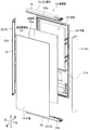
図5に示すように、引出式の断熱扉5aは、ガラス製の外板10Aと、扉枠20Aと、両面テープ70Aと、飛散防止フィルム90Aと、外板側の真空断熱材31Aと、内板側の真空断熱材32Aと、発泡断熱材50Aと、補強板部材80Aと、内板60Aと、内板側の真空断熱材32Aと、を備えて構成されている。
≪Drawer-type insulated doors≫
Next, the drawer-type heat insulating door 5a will be described with reference to FIGS.
As shown in FIG. 5, the drawer-type heat insulating door 5a includes a glass
なお、図1に示す冷蔵庫1の各引出式の断熱扉3a,4a,5a,6aには、各貯蔵室側に、開口した箱型形状の断熱箱体(図示省略)が設けられている。図5に示すように、断熱扉5a(3a,4a,6a)は、断熱箱体(図示省略)が取り付けられる内板60Aの表面(前面)に、左右一対の金属製の補強板部材80Aと、内板側の真空断熱材32Aと、が取り付けられている点で、前記回動式の断熱扉2a,2b(図1参照)と相違している。
In addition, each drawer-type
<外板>
外板10Aは、前記回動式の断熱扉2aの外板10(図3参照)と同様、断熱扉5aの表面に設けられた横長の矩形のガラス製の平板材から成る。
<Outer plate>
Similar to the outer plate 10 (see FIG. 3) of the rotary heat insulating door 2a, the
<扉枠>
扉枠20Aは、外板10Aの周縁に設けられた四角形状の枠材である。扉枠20Aは、前記回動式の断熱扉2aの扉枠20(図3参照)と同様、枠部材21Aと、枠部材22Aと、枠部材23Aと、枠部材24Aとを横長の矩形状に連結して構成されている。上側の枠部材24Aには、利用者が開閉する際に手を掛けるための手掛部(図示省略)が形成されている。
<Door frame>
The
<両面テープ>
両面テープ70Aは、前記回動式の断熱扉2aの両面テープ70(図3参照)と同様、外板10Aを扉枠20Aに固定するための帯状の粘着テープである。両面テープ70Aは、枠部材21A,22A,23Aのテープ貼付部21Aa,22Aa,23Aaに貼着されている。
<Double-sided tape>
The double-
<飛散防止フィルム>
飛散防止フィルム90Aは、外板10Aの裏面に配置された樹脂製の薄膜状の部材である。飛散防止フィルム90Aは、フィルム状の部材であれば、その材質は特に限定されない。飛散防止フィルム90Aは、例えば、その一例を挙げると、外板10Aの裏面に設けられたポリエステルフィルム(PETフィルム)が挙げられる。そのPETフィルムは、強度が高くガラスが割れた際の飛散防止にも効果がある。また、PETフィルムは、透明性が高く、飛散防止フィルム90Aの基材の背面に印刷を施すことにより、フィルムを通して塗料層が見えるので、光沢が出て高級感がある意匠性の高い装飾シートとすることが可能である。また、PETフィルムは、耐熱・耐寒性に優れており、発泡断熱材50A(図6参照)の充填時の高温に対して、塗料層を保護できると共に、外板10Aから伝達される外気温の影響が少ない。
<Spattering prevention film>
The scattering prevention film 90 </ b> A is a resinous thin film member disposed on the back surface of the
<真空断熱材>
図6に示すように、引出式の断熱扉5aの空間40A内には、飛散防止フィルム90Aの裏面に配置された外板側の真空断熱材31Aと、内板60Aの表面に設けられた内板側の真空断熱材32Aとの二枚が内設されている。外板側の真空断熱材31Aと、内板側の真空断熱材32Aとは、前記回動式の断熱扉2bの真空断熱材30(図4参照)と相違して、段差部30aが無いガラス製の平板材から成る。
<Vacuum insulation>
As shown in FIG. 6, in the space 40A of the drawer-type heat insulating door 5a, the
外板側の真空断熱材31Aは、例えば、飛散防止フィルム90Aと同一の大きさに形成されている。外板側の真空断熱材31Aは、外板10Aの後方に飛散防止フィルム90Aを挟んで配置されている。図6及び図7に示すように、外板側の真空断熱材31Aの上下方向の長さL10が、内板側の真空断熱材32Aの上下方向の長さL20よりも長さL30だけ小さく形成されている(L10<L20)。外板側の真空断熱材31Aは、正面視して、表面の左右端部にねじ止めされる補強板部材80Aの外側まで配置されている。このため、外板側の真空断熱材31Aは、正面視して一対の補強板部材80Aに重なって配置されている。
The vacuum
図7に示すように、内板側の真空断熱材32Aは、内板60Aの表面(前面)において、左右の補強板部材80Aの間に上下方向に延びるように配置されている。このため、外板側の真空断熱材31Aの左右方向の長さL40は、内板側の真空断熱材32Aの左右方向の長さL50よりも大きく形成されている(L40>L50)。換言すると、内板側の真空断熱材32Aは、一対の補強板部材80A間に配置されると共に、上端部32Aaが外板側の真空断熱材31Aの上端部31Aaよりも高い位置に配置されている。
As shown in FIG. 7, the
このため、図6に示すように、外板側の真空断熱材31Aの上端部31Aaと、枠部材23Aとの間には、長さL60の空きスペースが形成されて、発泡断熱材50Aが外板10Aの裏面に接着される面積が広く形成されている。
For this reason, as shown in FIG. 6, an empty space of length L60 is formed between the upper end portion 31Aa of the vacuum
なお、図6では、外板側の真空断熱材31Aを飛散防止フィルム90Aから分離して図示しているが、外板10Aと飛散防止フィルム90Aと外板側の真空断熱材31Aとは、互いに密着した状態に配置されている。
In FIG. 6, the
<発泡断熱材>
発泡断熱材50Aは、外板10Aと扉枠20Aとで形成された空間40Aに、飛散防止フィルム90A及び真空断熱材31Aを介在させて充填されている。発泡断熱材50Aは、前記回動式の断熱扉2a内の発泡断熱材50(図4参照)と同様に、ウレタンフォーム等から成る。
<Foam insulation>
The foam heat insulating material 50A is filled in the space 40A formed by the
<内板>
内板60Aは、扉枠20Aの裏面に設けられる断熱箱体(図示省略)の表側の壁面を形成する樹脂製板材である。
<Inner plate>
The inner plate 60A is a resin plate material that forms a front wall surface of a heat insulating box (not shown) provided on the back surface of the
≪引出式の断熱扉の作用≫
次に、図5〜図7を主に参照しながら本発明の実施形態に係る冷蔵庫1の引出式の断熱扉5aの作用を組立順に沿って説明する。
≪Operation of drawer type heat insulation door≫
Next, the operation of the drawer-type heat insulating door 5a of the refrigerator 1 according to the embodiment of the present invention will be described in the order of assembly with reference mainly to FIGS.
引出式の断熱扉5aを組み立てる場合は、まず、図5に示すように、枠部材21A、枠部材22A及び枠部材23Aのテープ貼付部21Aa,22Aa,23Aaにそれぞれ両面テープ70A(図6参照)を貼り付ける。次に、外板10Aの右端部を枠部材24Aの係合溝24Aaに挿入し、外板10Aの左右上端部を枠部材21A、枠部材22A及び枠部材23Aの両面テープ70A(図4参照)にそれぞれ貼り付ける。
When assembling the drawer-type heat insulating door 5a, first, as shown in FIG. 5, double-
続いて、図6に示すように、外板10Aを下側に配置して、その外板10Aの裏面中央部に飛散防止フィルム90A及び外板側の真空断熱材31Aを付けて、空間40A内に発泡断熱材50Aの材料を充填する。次に、内板60Aの表面の左右に補強板部材80Aを配置して、補強板部材80Aを内板60Aを介在して内板60Aの裏面に設けられる断熱箱体(図示省略)にねじ止めする。この内板60Aを扉枠20Aの裏面側端部に取り付けて、空間40Aを閉塞する。このようにして断熱扉5aは、組み立てられる。
Subsequently, as shown in FIG. 6, the
このようにして組み立てられた引出式の断熱扉5aは、図6に示すように、空間40Aに充填された発泡断熱材50Aと、外板10Aと内板60Aとの間に介在された二枚の真空断熱材31A,32Aと、が内設されているので、断熱効果を向上させて省エネルギー化を図ることができる。
As shown in FIG. 6, the drawer-type heat insulating door 5a assembled in this way is two sheets interposed between the foam heat insulating material 50A filled in the space 40A and the
また、図7に示すように、外板側の真空断熱材31Aは、正面視して、一対の金属製の補強板部材80Aに重なって配置されるように幅広に形成されている。このため、貯蔵室内の冷気で冷却された補強板部材80Aの熱が断熱扉5aの表面から放射されるのを、外板側の真空断熱材31Aによって抑制することができる。
As shown in FIG. 7, the vacuum heat insulating material 31 </ b> A on the outer plate side is formed wide so as to overlap with the pair of metal reinforcing plate members 80 </ b> A when viewed from the front. For this reason, it is possible to suppress the heat of the reinforcing
また、内板側の真空断熱材32Aは、外板側の真空断熱材31Aよりも高さL30だけ高い位置まで形成されると共に、正面視して、左右の補強板部材80A間において、外板側の真空断熱材31Aと重ねって配置されている。このように、断熱扉5aは、内板側の真空断熱材32Aと、外板側の真空断熱材31Aとが発泡断熱材50Aを介在して重なった三重構造になっていることによって、断熱効果をさらに向上させることができる。
The
外板側の真空断熱材31Aの上端部31Aaと、枠部材23Aとの間は、外板側の真空断熱材31Aの長さL10が、内板側の真空断熱材32Aの長さL20よりも、小さく形成されている(L10<L20)。このため、外板側の真空断熱材31Aの上端部31Aaと枠部材23Aとの間は、長さL60が比較的大きく形成されて、広い空きスペースを確保することができるので、発泡断熱材50Aが外板10Aの裏面に当接する面積が広く形成されている。
Between the upper end portion 31Aa of the vacuum
このように、接着剤としての機能がある発泡断熱材50Aは、外板側の真空断熱材31A及び飛散防止フィルム90Aを覆った状態で外板10Aに広範囲に亘って接着されるので、特別な固定具及び接着剤を使用せずに、真空断熱材30Aを外板10Aにしっかりと固定させることができる。
その結果、両面テープ70Aと係合溝24Aa(図5参照)とで扉枠20Aに固定された外板10Aは、さらに、空間40Aに充填された発泡断熱材50Aが外板10Aの裏面に接着されることによって、扉枠20Aから離脱すること無くしっかりと固定させることができる。
As described above, the foam heat insulating material 50A having a function as an adhesive is bonded to the
As a result, in the
このため、断熱扉5aと同じ構造の図1に示す引出式の断熱扉6aも、同様に、外板10Aを扉枠20Aから剥離したり、離脱したりすること無くしっかりと固定させることができる。
また、真空断熱材31Aは、外板10Aに対して飛散防止フィルム90Aを介在して配置されていることによって、万が一、外板10Aが割れた際に、ガラスが飛散するのを抑制することができる。
For this reason, the drawer-type
Further, the vacuum heat insulating material 31 </ b> A is arranged with the anti-scattering film 90 </ b> A interposed with respect to the
≪変形例≫
なお、本発明は、前記実施形態に限定されるものではなく、その技術的思想の範囲内で種々の改造及び変更が可能であり、本発明はこれら改造及び変更された発明にも及ぶことは勿論である。なお、前記実施形態で説明したものと同一なものは、同一符号を付してその説明は省略する。
≪Modification≫
The present invention is not limited to the above-described embodiment, and various modifications and changes can be made within the scope of the technical idea. The present invention extends to these modifications and changes. Of course. In addition, the same thing as what was demonstrated in the said embodiment attaches | subjects the same code | symbol, and abbreviate | omits the description.
図8(a)は、断熱扉の変形例を示す横断面図である。
前記実施形態で説明した図4に示す断熱扉2aの真空断熱材30は、その一例として段差部30aを形成して、真空断熱材30と外板10との間に発泡断熱材50が入り込むことが可能な隙間Sを設けた場合を説明したが、これに限定されるものではない。
図8(a)に示すように、真空断熱材30Bは、外板10Bとの間に隙間SBを形成するために、端部30Bbを内板60B側に曲げて形成してもよい。このように形成すれば、発泡断熱材50Bが、隙間SB内に入り込んで、外板10Bに接着されるため、外板10Bをしっかりと断熱扉に保持させることができる。
Fig.8 (a) is a cross-sectional view which shows the modification of a heat insulation door.
The vacuum
As shown in FIG. 8A, the vacuum
図8(b)は、断熱扉の他の変形例を示す横断面図である。
また、図8(b)に示すように、真空断熱材30Cは、両側の端部30Cbを内板60C側に曲げて形成し、外板10Cとの間の両側に隙間SCがあるように形成してもよい。このようにしても、発泡断熱材50Cが、隙間SC内に入り込んで外板10Cに接着されるため、外板10Cをしっかりと断熱扉に保持させることができる。
FIG.8 (b) is a cross-sectional view which shows the other modification of a heat insulation door.
Further, as shown in FIG. 8B, the vacuum
図8(c)は、断熱扉の他の変形例を示す横断面図である。
また、図8(c)に示すように、真空断熱材30Dは、端部30Dbよりも中央部30Dc側に寄った位置に、外板10Dとの間に隙間SDが形成するために、内板60D側に山状に曲げて形成した折曲部30Ddを形成してもよい。このようにしても、発泡断熱材50Dが、隙間SC内に入り込んで外板10Dに接着されるため、外板10Cをしっかりと断熱扉に保持させることができる。
FIG.8 (c) is a cross-sectional view which shows the other modification of a heat insulation door.
Further, as shown in FIG. 8C, the vacuum
≪その他の変形例≫
また、実施形態及び変形例では、冷蔵庫1における断熱扉2a,3a,4a,5a,6aを例に挙げて説明したが、冷蔵庫1以外に、自動販売機、保冷宅配輸送箱、釣り具クーラー、食品配送箱、検体輸送用保冷ボックス、特殊冷蔵・冷凍庫、特殊冷凍車、冷凍コンテナ、ショーケース等の種々な用途に用いられる扉や、壁材として使用することも可能である。
≪Other variations≫
Moreover, in embodiment and the modification, although demonstrated taking the
また、外板10,10Aは、裏面に塗料を塗布したり、印刷したりして、単色調や模様を配しても構わない。
Further, the
1 冷蔵庫
2a,3a,4a,5a,6a 断熱扉
10,10A,10B,10C,10D 外板
20,20A 扉枠
30,30A,30B,30C,30D 真空断熱材
30a 段差部
30Ab,30Bb,30Cb,30Db 端部
30Dc 中央部
31A 外板側の真空断熱材
31Aa,32Aa 上端部
32A 内板側の真空断熱材
40,40A 空間
50,50A,50B,50C,50D 発泡断熱材
60,60A,60B,60C,60D 内板
80A 補強板部材
90A 飛散防止フィルム
L1 真空断熱材の内板側の長さ
L2 真空断熱材の外板側の長さ
L10 外板側の真空断熱材の長さ
L20 内板側の真空断熱材の長さ
SA,SB,SC,SD 隙間
DESCRIPTION OF SYMBOLS 1
Claims (4)
前記外板の周縁に設けられた扉枠と、
前記外板の裏面に配置された真空断熱材と、
前記外板と前記扉枠とで形成された空間に前記真空断熱材を介在させて充填された発泡断熱材と、
前記扉枠に設けられた内板と、を備えた冷蔵庫であって、
前記真空断熱材は、前記外板側の真空断熱材の長さが、前記内板側の真空断熱材の長さよりも小さく形成され、
前記空間内には、前記外板の裏面に密着した状態に配置された樹脂製の薄膜状の部材からなる飛散防止フィルムと、
前記飛散防止フィルムの裏面に密着した状態に配置された前記外板側の真空断熱材と、
前記内板の表面に設けられた前記内板側の真空断熱材と、
前記空間に充填された接着剤としての機能がある発泡断熱材と、
が内設され、
前記断熱扉は、前記内板を介在して前記内板の裏面に設けられる断熱箱体にねじ止めされた左右一対の金属製の補強板部材を備えた引出式扉からなり、
前記左右一対の補強板部材の表面全体を外側から覆って、正面視して前記左右一対の補強板部材に重なって配置された前記外板側の真空断熱材と、
前記左右一対の補強板部材間に配置された前記内板側の真空断熱材と、
前記発泡断熱材と、
を介在して重ねた三重構造になっていることを特徴とする冷蔵庫。 A glass outer plate provided on the surface of the heat insulating door;
A door frame provided at the periphery of the outer plate;
A vacuum heat insulating material disposed on the back surface of the outer plate;
A foam heat insulating material filled with the vacuum heat insulating material interposed in a space formed by the outer plate and the door frame;
A refrigerator provided with an inner plate provided on the door frame,
The vacuum heat insulating material is formed such that the length of the vacuum heat insulating material on the outer plate side is smaller than the length of the vacuum heat insulating material on the inner plate side ,
In the space, an anti-scattering film made of a resinous thin film-like member disposed in close contact with the back surface of the outer plate,
A vacuum heat insulating material on the outer plate disposed in close contact with the back surface of the anti-scattering film; and
A vacuum heat insulating material on the inner plate provided on the surface of the inner plate;
A foam insulation having a function as an adhesive filled in the space;
Is installed,
The heat insulating door comprises a pull-out type door provided with a pair of left and right metal reinforcing plate members screwed to a heat insulating box provided on the back surface of the inner plate with the inner plate interposed therebetween,
Covering the entire surface of the pair of left and right reinforcing plate members from the outside, and the vacuum insulating material on the outer plate side disposed to overlap the pair of left and right reinforcing plate members in front view,
A vacuum heat insulating material on the inner plate disposed between the pair of left and right reinforcing plate members;
The foam insulation,
Refrigerator characterized by having a triple structure with the intervening layers .
Priority Applications (2)
| Application Number | Priority Date | Filing Date | Title |
|---|---|---|---|
| JP2015078680A JP6562682B2 (en) | 2015-04-07 | 2015-04-07 | refrigerator |
| CN201610191448.5A CN106052276B (en) | 2015-04-07 | 2016-03-30 | Refrigerator |
Applications Claiming Priority (1)
| Application Number | Priority Date | Filing Date | Title |
|---|---|---|---|
| JP2015078680A JP6562682B2 (en) | 2015-04-07 | 2015-04-07 | refrigerator |
Publications (2)
| Publication Number | Publication Date |
|---|---|
| JP2016200294A JP2016200294A (en) | 2016-12-01 |
| JP6562682B2 true JP6562682B2 (en) | 2019-08-21 |
Family
ID=57423644
Family Applications (1)
| Application Number | Title | Priority Date | Filing Date |
|---|---|---|---|
| JP2015078680A Active JP6562682B2 (en) | 2015-04-07 | 2015-04-07 | refrigerator |
Country Status (2)
| Country | Link |
|---|---|
| JP (1) | JP6562682B2 (en) |
| CN (1) | CN106052276B (en) |
Families Citing this family (3)
| Publication number | Priority date | Publication date | Assignee | Title |
|---|---|---|---|---|
| JP2019196856A (en) * | 2018-05-09 | 2019-11-14 | 日立グローバルライフソリューションズ株式会社 | refrigerator |
| KR20210006740A (en) * | 2019-07-09 | 2021-01-19 | 엘지전자 주식회사 | Vacuum adiabatic body and refrigerator |
| US20240019194A1 (en) * | 2020-11-02 | 2024-01-18 | Lg Electronics Inc. | Vacuum adiabatic body |
Family Cites Families (10)
| Publication number | Priority date | Publication date | Assignee | Title |
|---|---|---|---|---|
| TR199700083A2 (en) * | 1997-02-03 | 1998-08-21 | Ar�El�K A.�. | Refrigerator door with high insulation and recycling performance. |
| JP3876551B2 (en) * | 1998-09-29 | 2007-01-31 | 三菱電機株式会社 | Insulation and refrigerator |
| JP5303415B2 (en) * | 2009-09-28 | 2013-10-02 | 日立アプライアンス株式会社 | refrigerator |
| JP2011237087A (en) * | 2010-05-10 | 2011-11-24 | Hitachi Appliances Inc | Refrigerator |
| JP5372877B2 (en) * | 2010-09-14 | 2013-12-18 | 日立アプライアンス株式会社 | Vacuum heat insulating material and refrigerator using the same |
| JP2015017736A (en) * | 2013-07-10 | 2015-01-29 | 日立アプライアンス株式会社 | Refrigerator |
| JP6002641B2 (en) * | 2013-08-20 | 2016-10-05 | 日立アプライアンス株式会社 | Vacuum insulation and refrigerator |
| JP6113610B2 (en) * | 2013-09-05 | 2017-04-12 | 日立アプライアンス株式会社 | refrigerator |
| JP2015052398A (en) * | 2013-09-05 | 2015-03-19 | 日立アプライアンス株式会社 | Refrigerator |
| JP6313035B2 (en) * | 2013-09-24 | 2018-04-18 | 東芝ライフスタイル株式会社 | refrigerator |
-
2015
- 2015-04-07 JP JP2015078680A patent/JP6562682B2/en active Active
-
2016
- 2016-03-30 CN CN201610191448.5A patent/CN106052276B/en not_active Expired - Fee Related
Also Published As
| Publication number | Publication date |
|---|---|
| CN106052276A (en) | 2016-10-26 |
| CN106052276B (en) | 2018-12-07 |
| JP2016200294A (en) | 2016-12-01 |
Similar Documents
| Publication | Publication Date | Title |
|---|---|---|
| JP5193980B2 (en) | refrigerator | |
| RU2455587C2 (en) | Refrigerating device | |
| WO2014038150A1 (en) | Refrigerator | |
| JP5303415B2 (en) | refrigerator | |
| JP6313035B2 (en) | refrigerator | |
| JP6562682B2 (en) | refrigerator | |
| NZ518158A (en) | Refrigerating device | |
| EP2789938A1 (en) | Refrigerator | |
| JP2012211721A (en) | Refrigerator | |
| JP5897635B2 (en) | refrigerator | |
| JP5865581B2 (en) | refrigerator | |
| RU2505761C2 (en) | Refrigerating device, and manufacturing method of refrigerating device door | |
| JP2017026251A (en) | refrigerator | |
| JP6232578B2 (en) | Insulated door | |
| US20180259243A1 (en) | Refrigerator | |
| JP2016180568A (en) | refrigerator | |
| JP5092806B2 (en) | vending machine | |
| JP6875221B2 (en) | refrigerator | |
| JP2005323830A (en) | Sash structure of glass door and freezing/refrigerating showcase using the same | |
| JP3945553B2 (en) | Heat insulation box | |
| JP2010270930A (en) | Partitioning frame of cooling storage | |
| JP2019148421A (en) | refrigerator | |
| WO2023047606A1 (en) | Heat insulation door and refrigerator using same | |
| JP6292990B2 (en) | refrigerator | |
| JP5537686B2 (en) | refrigerator |
Legal Events
| Date | Code | Title | Description |
|---|---|---|---|
| A621 | Written request for application examination |
Free format text: JAPANESE INTERMEDIATE CODE: A621 Effective date: 20180226 |
|
| A977 | Report on retrieval |
Free format text: JAPANESE INTERMEDIATE CODE: A971007 Effective date: 20181221 |
|
| A131 | Notification of reasons for refusal |
Free format text: JAPANESE INTERMEDIATE CODE: A131 Effective date: 20190108 |
|
| A521 | Written amendment |
Free format text: JAPANESE INTERMEDIATE CODE: A523 Effective date: 20190306 |
|
| TRDD | Decision of grant or rejection written | ||
| A01 | Written decision to grant a patent or to grant a registration (utility model) |
Free format text: JAPANESE INTERMEDIATE CODE: A01 Effective date: 20190709 |
|
| A61 | First payment of annual fees (during grant procedure) |
Free format text: JAPANESE INTERMEDIATE CODE: A61 Effective date: 20190723 |
|
| R150 | Certificate of patent or registration of utility model |
Ref document number: 6562682 Country of ref document: JP Free format text: JAPANESE INTERMEDIATE CODE: R150 |