JP6561910B2 - Passenger conveyor - Google Patents

Passenger conveyor Download PDF

Info

Publication number
JP6561910B2
JP6561910B2 JP2016097092A JP2016097092A JP6561910B2 JP 6561910 B2 JP6561910 B2 JP 6561910B2 JP 2016097092 A JP2016097092 A JP 2016097092A JP 2016097092 A JP2016097092 A JP 2016097092A JP 6561910 B2 JP6561910 B2 JP 6561910B2
Authority
JP
Japan
Prior art keywords
edge
handrail
groove
balustrade panel
handrail deck
Prior art date
Legal status (The legal status is an assumption and is not a legal conclusion. Google has not performed a legal analysis and makes no representation as to the accuracy of the status listed.)
Active
Application number
JP2016097092A
Other languages
Japanese (ja)
Other versions
JP2017202928A (en
Inventor
雅也 渡邉
雅也 渡邉
Current Assignee (The listed assignees may be inaccurate. Google has not performed a legal analysis and makes no representation or warranty as to the accuracy of the list.)
Fujitec Co Ltd
Original Assignee
Fujitec Co Ltd
Priority date (The priority date is an assumption and is not a legal conclusion. Google has not performed a legal analysis and makes no representation as to the accuracy of the date listed.)
Filing date
Publication date
Application filed by Fujitec Co Ltd filed Critical Fujitec Co Ltd
Priority to JP2016097092A priority Critical patent/JP6561910B2/en
Publication of JP2017202928A publication Critical patent/JP2017202928A/en
Application granted granted Critical
Publication of JP6561910B2 publication Critical patent/JP6561910B2/en
Active legal-status Critical Current
Anticipated expiration legal-status Critical

Links

Images

Description

本発明は、エスカレータその他の乗客コンベアに関し、特に、照明器具が取付可能に構成された欄干を有する乗客コンベアに関する。   The present invention relates to an escalator and other passenger conveyors, and more particularly, to a passenger conveyor having a balustrade that is configured so that lighting fixtures can be attached thereto.

エスカレータは、乗客を搬送する手段としては勿論、近年、建築デザインの重要な要素となっており、乗客を搬送する踏段の走行路の両脇に設置された欄干を構成する欄干パネルを透明なガラス製にした上で、当該欄干パネルの上端に沿って照明器具を設け、意匠性を向上させたものが多く設置されている。   In recent years, escalators have become an important element of architectural design as a means of transporting passengers, and transparent glass is used for the balustrade panels that constitute the railings installed on both sides of the runway of the steps that transport passengers. Many of them have been improved by providing lighting fixtures along the upper end of the balustrade panel.

照明器具は、例えば、特許文献1に開示されているエスカレータでは、以下のようにして設けられている(特許文献1の図2を参照。)。特許文献1のエスカレータは、下方に開口し、長手方向に延びる溝部を有する長尺の取付部材を有しており、当該取付部材は、欄干パネルの上部縁辺部に前記溝部が嵌った状態で当該欄干パネルに固定されている。   For example, an escalator disclosed in Patent Document 1 is provided as follows (see FIG. 2 of Patent Document 1). The escalator of Patent Document 1 has a long attachment member having a groove portion that opens downward and extends in the longitudinal direction, and the attachment member is in a state where the groove portion is fitted to the upper edge portion of the balustrade panel. It is fixed to the balustrade panel.

取付部材には、略「コ」字状の横断面を有する長尺の手摺デッキが被されている。手摺デッキは、欄干パネルに対し、前記走行路とは反対側に大きく張り出していて、当該張り出した部分の下側に照明器具が設けられている。また、手摺デッキの前記反対側の端部と取付部材との間には、前記照明器具の下方を覆う照明カバーが設けられている。   The attachment member is covered with a long handrail deck having a substantially “U” -shaped cross section. The handrail deck projects greatly from the balustrade panel on the side opposite to the travel path, and a lighting device is provided below the projecting portion. A lighting cover is provided between the opposite end of the handrail deck and the mounting member to cover the lower side of the lighting fixture.

一方、手摺デッキの、欄干パネルに対し前記走行路側の端縁部は、当該欄干パネルに向かって折り曲げられている。当該端縁部の先端(以下、「デッキ端」と言う。)と欄干パネルとの間には、製造上その他の理由によって隙間が空いてしまう。手摺デッキは、一般的に、ステンレス鋼などの金属材料で形成されているため、踏段で搬送される乗客の指が誤って前記デッキ端で擦られると怪我をするおそれがある。そこで、特許文献1では、前記端縁部を覆う端縁カバーとして「緩衝パッキング」が設けられている(特許文献1の段落〔0018〕、図2)。   On the other hand, the edge of the handrail deck on the side of the traveling path with respect to the balustrade panel is bent toward the balustrade panel. A gap is left between the tip of the edge (hereinafter referred to as “deck end”) and the balustrade panel for other reasons in manufacturing. Since the handrail deck is generally formed of a metal material such as stainless steel, there is a risk of injury if a passenger's finger transported on a step is accidentally rubbed at the end of the deck. Therefore, in Patent Document 1, “buffer packing” is provided as an edge cover that covers the edge portion (paragraph [0018] of FIG. 2, FIG. 2).

当該パッキングは、前記端縁部が嵌る溝を有しており、当該溝に端縁部が嵌め込まれて装着されている。特許文献1において、欄干を組み立てる際には、踏段の両脇に立設した欄干パネルの上部縁辺部に取付部材を取り付けた後、その取付部材に、予めパッキングを装着させた手摺デッキを載置する。そして、載置された手摺デッキと取付部材とをボルトで締結する(特許文献1の段落〔0019〕、〔0020〕)。   The packing has a groove into which the end edge portion is fitted, and the end edge portion is fitted into the groove. In Patent Document 1, when assembling the balustrade, after attaching an attachment member to the upper edge of the balustrade panel erected on both sides of the step, a handrail deck on which packing has been previously mounted is placed on the attachment member To do. And the mounted handrail deck and an attachment member are fastened with a volt | bolt (paragraphs [0019] and [0020] of patent document 1).

これにより、前記端縁部が緩衝パッキングによって覆われるため、デッキ端で乗客の指が擦られるのを防止できる。   Thereby, since the said edge part is covered with buffer packing, it can prevent that a passenger | crew's finger is rubbed by the deck end.

2006−193294号公報2006-193294

ところで、パッキング(端縁カバー)は、経年劣化や損傷などにより交換する必要が生じる。この場合、特許文献1では、パッキングを手摺デッキから取り外すには、先ず、ボルトによる締結を解除して手摺デッキを取付部材から取り外す必要がある。   By the way, the packing (edge cover) needs to be replaced due to aging or damage. In this case, in Patent Document 1, in order to remove the packing from the handrail deck, first, it is necessary to release the fastening by the bolt and remove the handrail deck from the mounting member.

しかしながら、手摺デッキからパッキングを取り外すためだけに、手摺デッキを取付部材から取り外さなければならないのは、非常に手間である。   However, it is very troublesome to remove the handrail deck from the mounting member only to remove the packing from the handrail deck.

なお、上記した課題は、エスカレータに限らず、他の乗客コンベア、例えば、移動歩道にも共通する。   In addition, the above-mentioned subject is common not only to an escalator but to other passenger conveyors, for example, a moving sidewalk.

本発明は、上記した課題に鑑み、取付部材から手摺デッキを取り外すことなく、当該手摺デッキに装着された端縁カバーの交換ができる乗客コンベアを提供することを目的とする。   An object of this invention is to provide the passenger conveyor which can replace | exchange the edge cover with which the said handrail deck was mounted | worn, without removing a handrail deck from an attachment member in view of an above-described subject.

上記の目的を達成するため、本発明に係る乗客コンベアは、循環走行して乗客を搬送する無端搬送体と、前記無端搬送体の走行路を含む乗客の通路に沿って立設された複数の欄干パネルと、長手方向に延びる溝部を有する長尺のブロック体からなり、前記溝部が前記欄干パネルの縁辺部に嵌合され、当該複数の欄干パネルの前記縁辺部に沿って列設された複数の取付部材と、角筒体の一側壁の一部が全長に亘って開口されてなる板体からなり、開口部を前記縁辺部に向けて前記取付部材に被せられ、前記複数の取付部材に列設状態で取り付けられた複数の手摺デッキと、前記手摺デッキに装着された、可撓性を有するバー状をした合成樹脂製の端縁カバーと、を有し、前記手摺デッキは、前記欄干パネルに対して前記通路と反対側に張り出した部分に照明器具が組み込み可能に構成されていると共に、前記通路側の端縁部は、前記取付部材の一部を囲むように前記欄干パネルの前記通路側の主面に向かって屈曲されていて、前記端縁カバーは、長さ方向に形成された一条の溝を有し、当該溝の幅が前記端縁部の厚みよりも大きく設定されていて、前記溝が前記端縁部の長手方向の一端から挿通されて、前記手摺デッキに装着されていることを特徴とする。   In order to achieve the above object, a passenger conveyor according to the present invention includes an endless transport body that travels in a circulating manner and transports passengers, and a plurality of erections that are installed along a passage of a passenger including a travel path of the endless transport body. A balustrade panel and a long block body having a groove extending in the longitudinal direction, the groove being fitted to an edge of the balustrade panel, and a plurality of lines arranged along the edge of the balustrade panel And a plate body in which a part of one side wall of the rectangular tube body is opened over its entire length, and the opening is covered with the mounting member toward the edge, and the plurality of mounting members A plurality of handrail decks mounted in a row, and a flexible bar-shaped synthetic resin edge cover attached to the handrail deck, wherein the handrail deck includes the balustrade deck Projects to the opposite side of the passage from the panel The lighting fixture can be incorporated into the portion, and the edge portion on the passage side is bent toward the main surface on the passage side of the balustrade panel so as to surround a part of the attachment member. The edge cover has a single groove formed in the length direction, and the width of the groove is set larger than the thickness of the edge portion, and the groove is in the longitudinal direction of the edge portion. It is inserted through one end of the handrail and is mounted on the handrail deck.

また、前記端縁部における前記一端は、前記列設状態で取り付けられた前記複数の手摺デッキの内、一端側に設置された端部手摺デッキの端縁部における、これに隣接する手摺デッキから遠い方の一端であることを特徴とする。   Further, the one end of the end edge portion is from a handrail deck adjacent to the end edge portion of the end handrail deck installed on one end side of the plurality of handrail decks attached in the row state. It is characterized by being one end of the far side.

あるいは、前記列設状態で取り付けられた前記複数の手摺デッキの内、両端部に設置された手摺デッキを除く中間に設置された中間手摺デッキの端縁部の一部が切除されていて、残余の端縁部の一端が、前記端縁カバーが挿通される前記一端であることを特徴とする。   Or, among the plurality of handrail decks mounted in the row state, a part of the edge portion of the intermediate handrail deck installed in the middle excluding the handrail deck installed at both ends is cut off, and the remaining One end of the end edge portion is the one end through which the end cover is inserted.

また、前記端縁カバーに外力が加わって、前記溝の深さ方向、前記欄干パネルに向かってスライドされた際、当該端縁カバーにおいて前記主面に対向する部分が当該主面に当接してそれ以上のスライドが制限されることにより、当該端縁カバーの前記手摺デッキからの前記深さ方向への抜け防止が図られていることを特徴とする。   Further, when an external force is applied to the edge cover and the groove is slid toward the balustrade panel in the depth direction of the groove, a portion of the edge cover that faces the main surface comes into contact with the main surface. By restricting further slides, the edge cover is prevented from coming off from the handrail deck in the depth direction.

さらに、前記端縁カバーは、前記溝に対して前記取付部材と反対側に、前記主面に対して傾斜した斜面を有し、当該斜面の前記主面と成す角度が45度以下であることを特徴とする。   Further, the edge cover has a slope inclined with respect to the main surface on the opposite side of the mounting member with respect to the groove, and an angle formed with the main surface of the slope is 45 degrees or less. It is characterized by.

また、前記合成樹脂は、潤滑剤が添加されたものであることを特徴とする。   Further, the synthetic resin is characterized in that a lubricant is added.

上記の構成からなる乗客コンベアによれば、手摺デッキの端縁部に装着された端縁カバーは、長さ方向に形成された一条の溝が端縁部の長手方向の一端から挿通されて装着されており、溝の幅が端縁部の厚みよりも大きいため、端縁カバーは、前記一端から長さ方向に引き抜いて端縁部(手摺デッキ)から取り外すことができる。また、端縁カバーは、溝を端縁部に、端縁部の長手方向の一端から挿通することにより装着することができる。これにより、取付部材から手摺デッキを取り外すことなく、手摺デッキに装着された端縁カバーの交換をすることができる。   According to the passenger conveyor having the above-described configuration, the edge cover mounted on the edge portion of the handrail deck is mounted with a single groove formed in the length direction inserted from one end in the longitudinal direction of the edge portion. Since the width of the groove is larger than the thickness of the edge portion, the edge cover can be removed from the edge portion (handrail deck) by pulling out from the one end in the length direction. Further, the edge cover can be mounted by inserting the groove into the edge portion from one end in the longitudinal direction of the edge portion. Thereby, the edge cover attached to the handrail deck can be replaced without removing the handrail deck from the mounting member.

実施形態に係るエスカレータの概略構成を示す斜視図である。It is a perspective view which shows schematic structure of the escalator which concerns on embodiment. 実施形態に係るエスカレータを構成する欄干の概略構成を示す断面図である。It is sectional drawing which shows schematic structure of the balustrade which comprises the escalator which concerns on embodiment. 手摺デッキの概略構成を示す、一部切欠き斜視図である。It is a partially cutaway perspective view showing a schematic configuration of a handrail deck. (a)は、図2におけるA部の拡大断面図であり、(b)は紙面に垂直方向における別の位置で切断し、A部と同じ向きに見た拡大断面図である。(A) is an expanded sectional view of the A part in FIG. 2, (b) is an expanded sectional view cut | disconnected in another position in the orthogonal | vertical direction to the paper surface, and seeing in the same direction as the A part. 実施形態における、(a)はくさび部材の正面図、(b)は同下面図、(c)は同左側面図、(d)はI-I線断面図、(e)はII-II線断面図、(f)はIII-III線断面図をそれぞれ示している。In the embodiment, (a) is a front view of the wedge member, (b) is a bottom view thereof, (c) is a left side view thereof, (d) is a sectional view taken along line II, and (e) is a sectional view taken along line II-II, (F) has each shown the III-III sectional view. 取付部材において、上記くさび部材が設けられる箇所の、(a)は上から見た図を、(b)は図4(a)におけるB-B線断面図を、(c)はVI-VI線断面図を、(d)はV-V線断面図を、(e)はIV-IV線断面図をそれぞれ示している。In the attachment member, (a) is a view seen from above, (b) is a cross-sectional view taken along line BB in FIG. 4 (a), and (c) is a VI-VI line. A sectional view, (d) shows a sectional view taken along the line VV, and (e) shows a sectional view taken along the line IV-IV. 欄干パネルに対する取付部材の固定が解除された状態における、(a)は図4(a)と同じ位置で切断した拡大断面図であり、(b)は図4(b)と同じ位置で切断した拡大断面図である。4A is an enlarged cross-sectional view cut at the same position as FIG. 4A, and FIG. 4B is cut at the same position as FIG. 4B in a state where the fixing of the attachment member to the balustrade panel is released. It is an expanded sectional view. 欄干パネルに対する取付部材の固定を解除する方法を説明するための図である。It is a figure for demonstrating the method to cancel | release fixing of the attachment member with respect to a balustrade panel. 実施形態における固定器具において、(a)は欄干パネルを固定保持した状態における斜視図であり、(b)は(a)に示す状態から可動ブラケットを固定ブラケットに対してスライドさせた状態を示す斜視図である。In the fixing device in the embodiment, (a) is a perspective view in a state where the balustrade panel is fixedly held, and (b) is a perspective view showing a state in which the movable bracket is slid with respect to the fixed bracket from the state shown in (a). FIG. 実施形態における固定器具およびその近傍の拡大図である。It is an enlarged view of the fixing device and its vicinity in an embodiment. 実施形態における固定器具において、欄干パネルの固定が解除された状態を示す斜視図である。It is a perspective view which shows the state by which fixation of the balustrade panel was cancelled | released in the fixing device in embodiment. 実施形態での、欄干パネルの交換作業途中の状態を示す図である。It is a figure which shows the state in the middle of replacement work of the balustrade panel in embodiment. (a)は、端縁カバーの斜視図であり、(b)は、同横断面図である。(A) is a perspective view of an edge cover, (b) is the cross-sectional view. 手摺デッキに端縁カバーが取り付けられた状態での、端縁カバーの交換口およびその近傍を下から見上げた斜視図である。It is the perspective view which looked up at the exchange port of an edge cover, and its vicinity from the bottom in the state in which the edge cover was attached to the handrail deck. 上記交換口にキャップが取り付けられた状態を示す図である。It is a figure which shows the state in which the cap was attached to the said exchange port. 手摺デッキから端縁カバーが取り外された状態での、上記交換口を示す図である。It is a figure which shows the said exchange port in the state from which the edge cover was removed from the handrail deck. 下端部手摺デッキの一端およびその近傍の斜視図である。It is a perspective view of the end of the lower end part handrail deck, and its vicinity. (a)、(b)は、それぞれ、端縁カバーの他の例の横断面図である。(A), (b) is a cross-sectional view of the other example of an edge cover, respectively.

以下、本発明に係るエスカレータの実施形態について、図面を参照しながら説明する。なお、図2、図10、および図12においては、煩雑さを避けるため、断面であることを示すハッチングは省略している。   Hereinafter, embodiments of an escalator according to the present invention will be described with reference to the drawings. In FIGS. 2, 10, and 12, hatching indicating a cross section is omitted to avoid complexity.

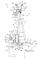
図1に示すように、実施形態に係るエスカレータ10は、環状に連結されて循環走行し、乗客を搬送する無端搬送体である複数の踏段12を有する。踏段12の走行路および上下の昇降口を含む乗客の通路PWの両側には、欄干14,16が設置されている。なお、図1において、欄干14,16に設けられた後述の照明器具32は省略している。   As shown in FIG. 1, the escalator 10 according to the embodiment includes a plurality of steps 12 that are endless transport bodies that are connected in a circular manner and circulate and transport passengers. Railings 14 and 16 are installed on both sides of the passenger passage PW including the travel path of the steps 12 and the upper and lower elevators. In addition, in FIG. 1, the below-mentioned lighting fixture 32 provided in the balustrades 14 and 16 is abbreviate | omitted.

欄干14,16の各々は、通路PWに沿って列設された複数の欄干パネル11,13,15,17,19,21,23,25,27,29,31を有する(図1において、欄干パネルは、片側の欄干14を構成する欄干パネルのみに符号を付している。)。欄干パネル11,…,31の各々は、例えば、ガラス製であり、強化板ガラスの片面に飛散防止フィルムが貼着されてなるものである。ここで、複数の欄干パネル11,…,31の内、列設方向において両端部に設けられた端部欄干パネルを特に区別する必要がある場合、当該端部欄干パネルを「ニューエルパネル11,31」と称し、ニューエルパネル11,31以外の欄干パネルを「中間パネル13,…,29」と称することとする。   Each of the balustrades 14 and 16 has a plurality of balustrade panels 11, 13, 15, 17, 19, 21, 23, 25, 27, 29, 31 arranged along the passage PW (in FIG. 1, the balustrades) Only the balustrade panel which comprises the balustrade 14 of the one side is attached | subjected the code | symbol. Each of the balustrade panels 11,..., 31 is made of, for example, glass, and is formed by attaching a scattering prevention film to one side of a reinforced plate glass. Here, among the plurality of balustrade panels 11,..., 31, when it is necessary to particularly distinguish the end balustrade panels provided at both ends in the row direction, the end balustrade panels are referred to as “New L panels 11, 31. The balustrade panel other than the Newell panels 11 and 31 will be referred to as “intermediate panels 13,..., 29”.

欄干パネル11,…,31の外周には、ガイドレール(図1では不図示)に案内され、踏段12と同じ向きに同じ速度で循環走行する無端ベルト状をした移動手摺20,22がそれぞれ設けられている。前記ガイドレールに案内される移動手摺20,22は、欄干パネル11,…,31の上部縁辺部に沿って走行する区間(乗客が掴む区間)では、水平方向に走行した後、カーブして直線的に斜行し、またカーブして再び水平方向に走行する。   On the outer peripheries of the balustrade panels 11,..., 31 are provided handrails 20 and 22 in the form of endless belts which are guided by guide rails (not shown in FIG. 1) and circulate at the same speed as the steps 12 at the same speed. It has been. The moving handrails 20 and 22 guided by the guide rails travel in the horizontal direction along the upper edge of the balustrade panels 11,. The vehicle runs diagonally, curves again, and travels horizontally again.

エスカレータ10は、例えば、建築物内の階下のフロアDSと階上のフロアUSとの間に架け渡されて設置されている。エスカレータ10は、踏段12の走行の向きが切り替えられて、昇り用あるいは下り用として用いられ、踏段12に乗った乗客が、階下のフロアDSから階上のフロアUS、あるいは階上のフロアUSから階下のフロアDSへと搬送される。   The escalator 10 is installed, for example, between a floor DS below the floor and a floor US above the floor in the building. The escalator 10 is used for ascending or descending when the direction of travel of the step 12 is switched, and a passenger on the step 12 moves from the floor US upstairs to the floor US upstairs or the floor US upstairs. It is transported to the lower floor DS.

次に、欄干14,16について説明する。欄干14と欄干16とは、通路PWを挟んで対称的に設置されていて、基本的には、同じ構成を有している。よって、欄干14を代表に説明し、欄干16についての説明は省略することとする。   Next, the balustrades 14 and 16 will be described. The balustrade 14 and the balustrade 16 are symmetrically installed across the passage PW, and basically have the same configuration. Therefore, the balustrade 14 will be described as a representative, and the description of the balustrade 16 will be omitted.

欄干14を構成する複数枚の欄干パネル11,…,31の各々は、その下部縁辺部が、通路PWに沿って設置された、複数台の、図2に示す固定器具26によってトラス28に固定されている。欄干パネル11,…,31の1枚当り、そのサイズに応じた台数(2台〜4台)の固定器具26が用いられる。   Each of the plurality of balustrade panels 11,..., 31 constituting the balustrade 14 is fixed to the truss 28 with a plurality of fixing devices 26 shown in FIG. Has been. For each balustrade panel 11,..., 31, a number (2 to 4) of fixtures 26 corresponding to the size is used.

一方、複数枚の欄干パネル11,…,31の上部縁辺部には、被固定部材である取付部材30が複数本、列を成して固定され、取付部材30を介して照明器具32が取り付けられている。取付部材30は、アルミニウムの押出形材のブロック体からなり、欄干パネル13の縁辺部に沿って、その複数本が間隔を空けて列設されている。取付部材30は、移動手摺20が斜行する区間においては、直線状をしたものが、カーブする区間では、当該カーブに合わせた湾曲部分を有するものが用いられるが、いずれも横断面は略同じ形状をしている。   On the other hand, a plurality of mounting members 30 as fixed members are fixed in a row to the upper edge of the plurality of balustrade panels 11,..., 31, and the lighting fixture 32 is mounted via the mounting member 30. It has been. The attachment member 30 is made of a block body of extruded aluminum material, and a plurality of the attachment members 30 are arranged along the edge of the balustrade panel 13 at intervals. The attachment member 30 has a linear shape in the section where the moving handrail 20 is skewed, and a section having a curved portion matched to the curve is used in the curved section. It has a shape.

ここではニューエルパネル11に隣接する欄干パネル13を代表に、これを支持する固定器具26等の構成について説明する。   Here, the structure of the fixture 26 etc. which support the balustrade panel 13 adjacent to the Newell panel 11 will be described as a representative.

照明器具32は、取付部材30にL字アングル部材34を介して取り付けられたホルダ36を有し、ホルダ36には、蛍光ランプ38が嵌め込まれている。   The luminaire 32 has a holder 36 attached to the attachment member 30 via an L-shaped angle member 34, and a fluorescent lamp 38 is fitted in the holder 36.

取付部材30には、また、手摺デッキ40が設置されている。手摺デッキ40は、図3に示すように、角筒体の一側壁の一部が全長に亘って開口されてなる金属製の板体であって、横断面が略「コ」字状をした長尺部材である。手摺デッキ40は、金属板体を板金加工したものであり、当該金属には、例えば、鉄鋼材料(例えば、ステンレス鋼)が用いられる。   A handrail deck 40 is also installed on the attachment member 30. As shown in FIG. 3, the handrail deck 40 is a metal plate body in which a part of one side wall of the rectangular tube body is opened over the entire length, and the transverse section has a substantially “U” shape. It is a long member. The handrail deck 40 is obtained by processing a metal plate into a sheet metal. For the metal, for example, a steel material (for example, stainless steel) is used.

手摺デッキ40は、その開口部401を、図2に示すように、欄干パネル13の縁辺部(図示例では、上部縁辺部)に向けて取付部材30に被せられて、取付部材30に取付られている。   As shown in FIG. 2, the handrail deck 40 is attached to the attachment member 30 by covering the opening 401 toward the edge portion (upper edge portion in the illustrated example) of the balustrade panel 13. ing.

取り付けられた状態で、手摺デッキ40は、欄干パネル13に対して通路PWと反対側に大きく張り出しており、当該張り出した部分に照明器具32が組み込まれている。すなわち、このように大きく張り出させることによって、照明器具32を組み込み可能にしている。   In the attached state, the handrail deck 40 protrudes greatly to the opposite side of the passage PW with respect to the balustrade panel 13, and the lighting fixture 32 is incorporated in the protruding portion. In other words, the lighting fixture 32 can be incorporated by projecting it in this way.

手摺デッキ40の通路PW側とは反対側の端部と取付部材30との間には、蛍光ランプ38を覆うように、合成樹脂からなる半透明のランプカバー42が設けられている。   A translucent lamp cover 42 made of synthetic resin is provided between the end of the handrail deck 40 opposite to the passage PW side and the attachment member 30 so as to cover the fluorescent lamp 38.

手摺デッキ40の通路PW側の端縁部402は、取付部材30の一部(通路PW側端部)を取り囲むように欄干パネル13の通路PW側の主面13Bに向かって屈曲されている。端縁部402には、図3に示すように、厚み方向に貫通し、長さ方向に長い長孔403が開設されている。長孔403は、後述する締付ねじ60(図4、図4(a)、図7(a))を締め付けたり弛めたりするための六角レンチ(不図示)や、弛めねじ64(図8)を手摺デッキ40内側へ通すための貫通孔である。   The edge portion 402 on the passage PW side of the handrail deck 40 is bent toward the main surface 13B on the passage PW side of the balustrade panel 13 so as to surround a part of the attachment member 30 (end portion on the passage PW side). As shown in FIG. 3, the end edge portion 402 has a long hole 403 that penetrates in the thickness direction and is long in the length direction. The long hole 403 is a hexagon wrench (not shown) for tightening or loosening a tightening screw 60 (FIG. 4, FIG. 4 (a), FIG. 7 (a)) described later, or a loosening screw 64 (FIG. 8) is a through hole through which the handrail deck 40 passes.

手摺デッキ40の端縁部402には、図2に示すように、端縁カバー24が装着されているが、端縁カバー24については後述する。   As shown in FIG. 2, the edge cover 24 is attached to the edge 402 of the handrail deck 40. The edge cover 24 will be described later.

一本の手摺デッキ40は、一本の取付部材30よりも長く、複数本の取付部材30に亘って、一本の手摺デッキ40が取り付けられている。これにより、隣接する取付部材30は、両者に取り付けられた手摺デッキ40によって連結されていることになる。   One handrail deck 40 is longer than one attachment member 30, and one handrail deck 40 is attached over a plurality of attachment members 30. Thereby, the adjacent attachment member 30 is connected by the handrail deck 40 attached to both.

手摺デッキ40は、移動手摺20が斜行する区間では、図3に示すストレートのものが、移動手摺20がカーブする区間では、当該カーブに合わせて湾曲されたものが用いられる。手摺デッキ40は、複数本が長手方向における端面同士を突き合わせた形で列設されている。このように列設された手摺デッキ列の両端部の手摺デッキは、ニューエルパネル11,31(図1)の下部縁辺部に設置されている。ここで、ニューエルパネル11の下部縁辺部に設置された手摺デッキを「上端部手摺デッキ」と称し、ニューエルパネル31の下部縁辺部に設置された手摺デッキを「下端部手摺デッキ」と称し、上端部手摺デッキおよび下端部手摺デッキを除く中間に設置された手摺デッキを「中間手摺デッキ」と称することとする。   As for the handrail deck 40, the straight thing shown in FIG. 3 is used in the section where the moving handrail 20 is skewed, and the handrail deck 40 is curved according to the curve in the section where the moving handrail 20 curves. A plurality of handrail decks 40 are arranged in a form in which end faces in the longitudinal direction are butted together. The handrail decks at both ends of the handrail deck row arranged in this way are installed at the lower edge of the Newell panels 11 and 31 (FIG. 1). Here, the handrail deck installed at the lower edge of the Newell panel 11 is referred to as “upper end handrail deck”, the handrail deck installed at the lower edge of the Newell panel 31 is referred to as “lower end handrail deck”, and the upper end. The handrail deck installed in the middle excluding the handrail deck and the lower handrail deck is referred to as an “intermediate handrail deck”.

なお、列設された手摺デッキの各々は、いずれも同様の横断面形状をしている。また、列設された手摺デッキにおいて、照明器具32は、ニューエルパネル11の上部縁辺部からニューエルパネル31の上部縁辺部に至る区間に設置されている。   Each of the handrail decks arranged in line has the same cross-sectional shape. Further, in the handrail deck arranged in a row, the lighting fixture 32 is installed in a section from the upper edge of the Newell panel 11 to the upper edge of the Newell panel 31.

取付部材30上部には、図2に示すように、手摺デッキ40を介してガイドレール44が固定されている。ガイドレール44は、例えば、ステンレス鋼板を板金加工して作製されたものである。ガイドレール44は、取付部材30上面に対応する底板部44Aを有し、底板部44Aがスポット溶接(不図示)等により手摺デッキ40に接合されている。ガイドレール44は、また、底板部44Aの両端縁から上方へ立ち上がった縦板部44B,44Cと、縦板部44B,44Cの上端から外方へ張り出したフランジ部44D,44Eとを有する。   As shown in FIG. 2, a guide rail 44 is fixed to the upper portion of the attachment member 30 via a handrail deck 40. The guide rail 44 is produced, for example, by processing a stainless steel plate into a sheet metal. The guide rail 44 has a bottom plate portion 44A corresponding to the upper surface of the mounting member 30, and the bottom plate portion 44A is joined to the handrail deck 40 by spot welding (not shown) or the like. The guide rail 44 also includes vertical plate portions 44B and 44C that rise upward from both end edges of the bottom plate portion 44A, and flange portions 44D and 44E that protrude outward from the upper ends of the vertical plate portions 44B and 44C.

ガイドレール44において、両フランジ部44D,44Eに移動手摺20が取り付けられている。   In the guide rail 44, the moving handrail 20 is attached to both flange portions 44D and 44E.

上記のようにして、照明器具32やガイドレール44が設けられた取付部材30の欄干パネル13上部縁辺部への固定構造について、図4を参照しながら説明する。なお、図4(a)は、後述する締付ねじ60の軸心を含む平面で切断した図であり、図4(b)は、後述する六角穴付ボルト62の軸心を含む平面で切断した図である。   A structure for fixing the mounting member 30 provided with the lighting fixture 32 and the guide rail 44 to the upper edge of the balustrade panel 13 as described above will be described with reference to FIG. 4A is a view cut along a plane including an axis of a tightening screw 60 described later, and FIG. 4B is cut along a plane including an axis of a hexagon socket head bolt 62 described later. FIG.

図4に示すように、取付部材30は、欄干パネル13の縁辺部に沿った溝部46を有し、溝部46に欄干パネル13の縁辺部(本例では、上部縁辺部)が嵌め込まれている。   As shown in FIG. 4, the attachment member 30 has a groove 46 along the edge of the balustrade panel 13, and the edge of the balustrade panel 13 (upper edge in this example) is fitted into the groove 46. .

溝部46の第1壁面46Aは、欄干パネル13の第1主面13Aに平行に形成されている。第1壁面46Aに対向する第2壁面46Bは、溝部46の底部46Cからの高さが高くなる程(本例では、下方へ行くほど)欄干パネル13の第2主面13Bとの間隔が広くなるよう第2主面13Bに対し傾斜した面に形成されている。ここで、第2主面13Bが通路PWに面している側の主面である(図2)。   The first wall surface 46 </ b> A of the groove 46 is formed in parallel to the first main surface 13 </ b> A of the balustrade panel 13. The distance between the second wall surface 46B facing the first wall surface 46A and the second main surface 13B of the balustrade panel 13 increases as the height from the bottom 46C of the groove portion 46 increases (in this example, the lower the wall surface 46B). It is formed on a surface inclined with respect to the second main surface 13B. Here, the second main surface 13B is the main surface on the side facing the passage PW (FIG. 2).

欄干パネル13の上部縁辺部には、欄干パネル13を保護する保護部材48が被せられている。保護部材48は、横断面が略「コ」字状をした、ゴム製の押出成形材からなるクッションゴム50とこれよりも一回り大きな略「コ」字状の横断面を有する薄板状の金属カバー52とからなる。金属カバー52には、例えば、ステンレス鋼が用いられる。   A protective member 48 that protects the balustrade panel 13 is placed on the upper edge of the balustrade panel 13. The protective member 48 includes a cushion rubber 50 made of a rubber extruded material having a substantially “U” -shaped cross section, and a thin plate-like metal having a substantially “U” -shaped cross section that is slightly larger than the cushion rubber 50. And a cover 52. For the metal cover 52, for example, stainless steel is used.

欄干パネル13の第2主面13Bと溝部46の第2壁面46Bとの間には、くさび部材54が設けられている。くさび部材54は、金属材料(例えば、ステンレス鋼)、または硬質の合成樹脂からなる。   A wedge member 54 is provided between the second main surface 13B of the balustrade panel 13 and the second wall surface 46B of the groove 46. The wedge member 54 is made of a metal material (for example, stainless steel) or a hard synthetic resin.

図5に示すように、くさび部材54は、全体的に直角三角形状をした横断面を有する棒状をしている。くさび部材54は、一つの取付部材30に対し、複数本が間隔を空けて用いられる。   As shown in FIG. 5, the wedge member 54 has a bar shape having a cross section of a right triangle shape as a whole. A plurality of wedge members 54 are used at an interval with respect to one mounting member 30.

くさび部材54は、図4に示す状態で、欄干パネル13の第2主面13Bと対向する押圧面54Aと、溝部46の第2壁面46Bに沿った斜面54Bとを含む。略直角三角形状をした両側面以外の残りの面を下面54Cと称することとする。   The wedge member 54 includes a pressing surface 54A facing the second main surface 13B of the balustrade panel 13 and an inclined surface 54B along the second wall surface 46B of the groove portion 46 in the state shown in FIG. The remaining surfaces other than the both side surfaces having a substantially right triangle shape will be referred to as a lower surface 54C.

図5に示すように、くさび部材54の長さ方向中央部には、溝部46(図4)の深さ方向(本例では、上下方向)に貫通するねじ挿通孔54Dが開設されている。ねじ挿通孔54Dは、図4に示す状態において、平面視で、欄干パネル13の厚み方向に長い長孔である。   As shown in FIG. 5, a screw insertion hole 54 </ b> D penetrating in the depth direction (vertical direction in this example) of the groove 46 (FIG. 4) is formed in the center portion in the length direction of the wedge member 54. In the state shown in FIG. 4, the screw insertion hole 54 </ b> D is a long hole that is long in the thickness direction of the balustrade panel 13 in plan view.

くさび部材54の長さ方向において、ねじ挿通孔54Dの両側には、前記深さ方向(本例では、上下方向)に貫通する雌ねじ54E、54Fが形成されている。   In the length direction of the wedge member 54, female screws 54 </ b> E and 54 </ b> F that penetrate in the depth direction (vertical direction in this example) are formed on both sides of the screw insertion hole 54 </ b> D.

両雌ねじ54E,54Fのさらに両側には、後述する六角穴付ボルト62が挿入される挿通孔54G、54Hが開設されている。両挿通孔54G,54Hは、ねじ挿通孔54Dと同様の長孔である。   On both sides of both female screws 54E and 54F, insertion holes 54G and 54H into which hexagon socket head bolts 62 to be described later are inserted are opened. Both insertion holes 54G and 54H are elongated holes similar to the screw insertion hole 54D.

上記の構成からなるくさび部材54が設けられる取付部材30部分について、図6を参照しながら説明する。   The attachment member 30 portion on which the wedge member 54 having the above configuration is provided will be described with reference to FIG.

取付部材30には、くさび部材54のねじ挿通孔54D(図4(a)、図5)に対応させて、前記深さ方向(本例では、上下方向)に雌ねじ301が形成されている。   A female screw 301 is formed in the mounting member 30 in the depth direction (vertical direction in this example) corresponding to the screw insertion hole 54D (FIGS. 4A and 5) of the wedge member 54.

取付部材30の長さ方向において、雌ねじ301の両側には、くさび部材54の挿通孔54G,54H(図4(b)、図5)に対応させて、前記深さ方向(本例では、上下方向)に雌ねじ302、303が形成されている。雌ねじ302,303の上側の開口側には、図6(a)、(c)に示すように、深ざぐりがなされている。   In the length direction of the mounting member 30, on both sides of the female screw 301, the depth direction (in this example, the upper and lower sides) corresponding to the insertion holes 54 </ b> G and 54 </ b> H (FIG. 4B and FIG. 5) of the wedge member 54. Female screws 302 and 303 are formed in the direction). As shown in FIGS. 6 (a) and 6 (c), a counterbore is made on the opening side above the female screws 302 and 303.

取付部材30の、くさび部材54が設けられる部分において、雌ねじ301,302,303が形成されている箇所以外は、V-V線断面図に代表されるように、第2壁面46Bは平坦な面になっている。なお、V-V線断面図は、くさび部材54の雌ねじ54E,54F(図5(a))に対応する位置で切断した断面図である。   In the portion of the mounting member 30 where the wedge member 54 is provided, the second wall surface 46B is a flat surface, as represented by the cross-sectional view taken along the line VV, except where the female screws 301, 302, and 303 are formed. ing. The cross-sectional view taken along the line V-V is a cross-sectional view taken at a position corresponding to the female threads 54E and 54F (FIG. 5A) of the wedge member 54.

図4に戻り、欄干パネル13上部縁辺部への取付部材30の固定態様について説明する。図4(a)に示すように、平座金56、ばね座金58が嵌められた締付ねじ60が、くさび部材54のねじ挿通孔54Dに、溝部46の開口側(本例では、下側)から挿入され、取付部材30の雌ねじ301に螺合している。締付ねじ60には、例えば、低頭六角穴付ボルトが用いられる。   Returning to FIG. 4, the manner of fixing the attachment member 30 to the upper edge of the balustrade panel 13 will be described. As shown in FIG. 4A, the tightening screw 60 fitted with the flat washer 56 and the spring washer 58 is inserted into the screw insertion hole 54D of the wedge member 54 and the opening side (lower side in this example) of the groove 46. Inserted into the female screw 301 of the mounting member 30. For the fastening screw 60, for example, a low-head hexagon socket head cap screw is used.

図4(a)、(b)は、締付ねじ60の締め付けにより、取付部材30が欄干パネル13に固定されている状態を示している。不図示の六角レンチが用いられて締付ねじ60が締め付けられると、くさび部材54は、その斜面54Bが取付部材30の第2壁面46Bに案内されて斜行し、欄干パネル13の第2主面13Bに向かって押圧される。これにより、くさび部材54の押圧面54Aと取付部材30の第1壁面46Aとで欄干パネル13の上部縁辺部が締め付けられて(挟持されて)、取付部材30が欄干パネル13に固定されることとなる。なお、締付ねじ60を締め付けたり、弛めたりするときは、予め、端縁カバー24は、後述のようにして手摺デッキ40から取り外される(脱着される)。   4A and 4B show a state in which the attachment member 30 is fixed to the balustrade panel 13 by tightening the tightening screw 60. FIG. When the tightening screw 60 is tightened using a hexagon wrench (not shown), the wedge member 54 is skewed with the inclined surface 54B guided by the second wall surface 46B of the mounting member 30, and the second main body of the balustrade panel 13 is inclined. It is pressed toward the surface 13B. As a result, the upper edge of the balustrade panel 13 is clamped by the pressing surface 54A of the wedge member 54 and the first wall surface 46A of the attachment member 30, and the attachment member 30 is fixed to the balustrade panel 13. It becomes. Note that, when the tightening screw 60 is tightened or loosened, the edge cover 24 is previously removed (detached) from the handrail deck 40 as described below.

取付部材30の雌ねじ302,303(図6(a),(b),(c))の各々には、バー部材として六角穴付ボルト62(以下、単に「ボルト62」と言う。)がねじ込まれており、その頭部とは反対側のねじ部部分は、くさび部材54の挿通孔54G,54Hに挿入されている。   Hexagon socket head cap bolts 62 (hereinafter simply referred to as “bolts 62”) are screwed into the female threads 302 and 303 (FIGS. 6A, 6B and 6C) of the mounting member 30 as bar members. The screw portion opposite to the head portion is inserted into the insertion holes 54G and 54H of the wedge member 54.

取付部材30に設けたボルト62とくさび部材54に開設された挿通孔54G,54Hとは、締付ねじ60を締め付ける際および後述するように弛める際に、くさび部材54が締付ねじ60の軸心周りに回転するのを規制する規制手段として機能する。   The bolt 62 provided in the mounting member 30 and the insertion holes 54G and 54H provided in the wedge member 54 are used when the fastening member 60 is loosened when the fastening screw 60 is tightened and as will be described later. It functions as a restricting means that restricts rotation around the heart.

締付ねじ60を回すと、締付ねじ60が螺入されているくさび部材54は、締付ねじ60との間に生じる摩擦力によって、締付ねじ60の軸心周りに回転しようとする。この場合、何らの手当てをしないと、くさび部材54両端が周囲の部材にぶつかって、当該部材を損傷するおそれがある。   When the tightening screw 60 is turned, the wedge member 54 into which the tightening screw 60 is screwed tries to rotate around the axis of the tightening screw 60 due to the frictional force generated between the tightening screw 60 and the wedge member 54. In this case, if no care is taken, both ends of the wedge member 54 may collide with surrounding members, possibly damaging the member.

そこで、周囲の部材にぶつかる迄回転する手前で、挿通孔54G,54Hの内壁にボルト62を当接させて、それ以上回転するのを規制しているのである。   Therefore, the bolt 62 is brought into contact with the inner walls of the insertion holes 54G and 54H just before rotating until it hits a surrounding member, thereby restricting further rotation.

なお、当該規制手段として用いるバー部材は、ボルト62に限らず、例えば、ピンを用いても構わない。   The bar member used as the regulating means is not limited to the bolt 62, and for example, a pin may be used.

取付部材30の欄干パネル13に対する固定は、締付ねじ60を弛めることによって解除される。六角レンチ(不図示)を用いて締付ねじ60を弛めると、締付ねじ60は下方へ螺進する。その結果、締付ねじ60(の頭部)が、くさび部材54を第2壁面46Bに押圧する押圧力が解消され、ひいては、くさび部材54が欄干パネル13の第2主面13Bに向かって押圧される押圧力が解消される。   The fixing of the attachment member 30 to the balustrade panel 13 is released by loosening the fastening screw 60. When the fastening screw 60 is loosened using a hexagon wrench (not shown), the fastening screw 60 is screwed downward. As a result, the pressing force with which the fastening screw 60 (the head thereof) presses the wedge member 54 against the second wall surface 46B is eliminated, and consequently the wedge member 54 presses toward the second main surface 13B of the balustrade panel 13. The pressing force is canceled.

これにより、くさび部材54は、自重によって、図7(a)に示すように、その下面54Cが平座金56と当接するまで落下する。   As a result, the wedge member 54 falls by its own weight until its lower surface 54C comes into contact with the flat washer 56, as shown in FIG.

ところで、くさび部材54の保護部材48に対する食い込みの態様によっては、締付ねじ60を弛めても、くさび部材54が落下しない可能性がある。   By the way, depending on the manner in which the wedge member 54 bites into the protection member 48, the wedge member 54 may not fall even if the fastening screw 60 is loosened.

そこで、このような場合に、本実施形態では、弛めねじ64を用いる。弛めねじ64を用いた方法について、図8を参照しながら説明する。図8は、くさび部材54の雌ねじ54E(図5)の軸心を含む平面で切断したくさび部材54の横断面を含む断面図である。   Therefore, in this case, the loosening screw 64 is used in the present embodiment. A method using the loosening screw 64 will be described with reference to FIG. FIG. 8 is a cross-sectional view including a transverse section of the wedge member 54 cut along a plane including the axis of the female screw 54E (FIG. 5) of the wedge member 54. As shown in FIG.

締付ねじ60(図4(a))を弛めた状態で、弛めねじ64を手摺デッキ40の長孔403に挿入して、雌ねじ54Eの下側の開口部から螺合させる。弛めねじ64には、例えば、図示のような、比較的長めの六角穴付ボルトが用いられる。   In a state where the tightening screw 60 (FIG. 4A) is loosened, the loosening screw 64 is inserted into the elongated hole 403 of the handrail deck 40 and screwed into the opening on the lower side of the female screw 54E. As the loosening screw 64, for example, a relatively long hexagon socket head bolt as shown in the figure is used.

弛めねじ64をねじ込んで行くと、弛めねじ64は上向きに螺進し、その先端が取付部材30の第2壁面46Bに当接する。当接後も弛めねじ64をねじ込むと、弛めねじ64はこれ以上螺進できないため、くさび部材54に対し相対的に下向きに螺進させようとする力が作用する。その結果、くさび部材54は、下向きに移動し、これによってくさび部材54が弛むこととなる。   When the loosening screw 64 is screwed in, the loosening screw 64 is screwed upward, and its tip abuts against the second wall surface 46B of the mounting member 30. If the loosening screw 64 is screwed in even after the contact, the loosening screw 64 cannot be screwed any further, so that a force is exerted to make the wedge member 54 screw relatively downward. As a result, the wedge member 54 moves downward, which causes the wedge member 54 to loosen.

なお、弛めねじ64は、くさび部材54に常時螺合されているものではなく、欄干パネル13を取り外すときだけに用いられるものである。   The loosening screw 64 is not always screwed to the wedge member 54 and is used only when removing the balustrade panel 13.

また、上記実施形態では、締付ねじ60と弛めねじ64として六角穴付ボルトを用いたが、これに限らず、六角ボルトを用いても構わない。あるいは、十字穴付ねじを用いても構わない。   Moreover, in the said embodiment, although the hexagon socket head cap screw was used as the fastening screw 60 and the loosening screw 64, not only this but a hexagon head bolt may be used. Alternatively, a cross-recessed screw may be used.

以上説明したように、欄干パネル13の上部縁辺部に嵌め込まれた溝部46の第2壁面46Bと欄干パネル13の第2主面13Bとの間に設けられたくさび部材54において、溝部46の深さ方向(本例では、上下方向)に貫通するねじ挿通孔54Dに、溝部46の開口側(本例では、下方側)から挿入され、取付部材30に形成された雌ねじ301に螺合された締付ねじ60を弛めると、取付部材30の欄干パネル13の上部縁辺部に対する固定が解除される。すなわち、取付部材30に対し、その下方から取付部材30の固定の解除ができるため、取付部材30に対し、その上方に取り付けられている部材(本例では、ガイドレール44)を取り外す必要が無い。   As described above, in the wedge member 54 provided between the second wall surface 46B of the groove 46 fitted in the upper edge of the balustrade panel 13 and the second main surface 13B of the balustrade panel 13, the depth of the groove 46 is increased. The screw insertion hole 54D penetrating in the vertical direction (vertical direction in this example) is inserted from the opening side (lower side in this example) of the groove portion 46 and screwed into the female screw 301 formed in the mounting member 30. When the fastening screw 60 is loosened, the fixing of the attachment member 30 to the upper edge of the balustrade panel 13 is released. That is, since the fixing of the mounting member 30 can be released from the lower side with respect to the mounting member 30, it is not necessary to remove the member (the guide rail 44 in this example) mounted on the upper side of the mounting member 30. .

取付部材30の固定が解除されると、欄干パネル13の上部縁辺部が取付部材30の溝部46に欄干パネル13の厚み方向に遊びを持って嵌った状態となる。このようになると、後述するように、欄干パネル13の下端部の固定が解除された状態で欄干パネル13下端部の、踏段12の通路PW側前方が開放されていれば、欄干パネル13を取り外すことができる。   When the fixing of the attachment member 30 is released, the upper edge of the balustrade panel 13 is fitted in the groove 46 of the attachment member 30 with play in the thickness direction of the balustrade panel 13. In this case, as will be described later, the balustrade panel 13 is removed if the lower end of the balustrade panel 13 is released and the front of the step 12 on the passage PW side of the step 12 is opened, as will be described later. be able to.

そのような固定構造とした固定器具26について説明する。図9に示すように、固定器具26は、固定ブラケット66と可動ブラケット68とを有する。   The fixing device 26 having such a fixing structure will be described. As shown in FIG. 9, the fixing device 26 includes a fixed bracket 66 and a movable bracket 68.

固定ブラケット66は、受け部材70と後述する複数の(本例では、4個の)規制部材92,94,96,98とを含む   The fixing bracket 66 includes a receiving member 70 and a plurality (four in this example) of restricting members 92, 94, 96, and 98 to be described later.

受け部材70には、本例ではZ形鋼が用いられる。受け部材70には支持板74が溶接(例えば、隅肉溶接)により接合されている(溶接ビードについては不図示)。   In this example, Z-shaped steel is used for the receiving member 70. A support plate 74 is joined to the receiving member 70 by welding (for example, fillet welding) (the weld bead is not shown).

図2に示すように、トラス28には、L形アングル材76がボルト78・ナット80によって固定されている。L形アングル材76には、図9に示すように、長孔76Aが開設されており、ボルト78は長孔76Aおよびトラス28に開設された貫通孔(不図示)に挿入されて、ナット80とでL形アングル材76をトラス28に固定している。なお、図9において、トラス28とボルト78・ナット80は図示していない。   As shown in FIG. 2, an L-shaped angle member 76 is fixed to the truss 28 with bolts 78 and nuts 80. As shown in FIG. 9, the L-shaped angle member 76 has a long hole 76 </ b> A, and the bolt 78 is inserted into the long hole 76 </ b> A and a through hole (not shown) formed in the truss 28, and a nut 80. The L-shaped angle member 76 is fixed to the truss 28. In FIG. 9, the truss 28, the bolt 78, and the nut 80 are not shown.

トラス28に固定されたL形アングル材76のトラス28から垂直に立ち上がった壁部76Bと支持板74とがボルト82・ナット(ナットは、図には現れていない)によって締結されている。   The wall portion 76B of the L-shaped angle member 76 fixed to the truss 28 and vertically rising from the truss 28 and the support plate 74 are fastened by bolts 82 and nuts (the nut is not shown in the figure).

これにより、受け部材70(固定ブラケット66)は支持板74とL形アングル材76を介してトラス28に取り付けられている(固定されている。)。   Thus, the receiving member 70 (fixed bracket 66) is attached (fixed) to the truss 28 via the support plate 74 and the L-shaped angle member 76.

図9に戻り、受け部材70には、複数の(本例では、4個の)軸支部材84,86,88,90が溶接(例えば、隅肉溶接)により接合されている(溶接ビードについては不図示)。軸支部材84は、図2に示すように、L字状をした板体からなり、縦板部84Aにおいて受け部材70に接合されている。また、軸支部材84の横板部84Bの先端部分には、図9に示すように、その厚み方向に軸孔84Cが開設されている。   Returning to FIG. 9, a plurality (four in this example) of shaft support members 84, 86, 88, and 90 are joined to the receiving member 70 by welding (for example, fillet welding) (about the weld bead). Is not shown). As shown in FIG. 2, the shaft support member 84 is formed of an L-shaped plate and is joined to the receiving member 70 at the vertical plate portion 84 </ b> A. Further, as shown in FIG. 9, a shaft hole 84 </ b> C is formed in the distal end portion of the horizontal plate portion 84 </ b> B of the shaft support member 84 in the thickness direction.

他の3個の軸支部材86,88,90は受け部材70の長手方向に間隔を空けて配されている。軸支部材86,88,90の各々は軸支部材84と略同様の形状をし、受け部材70に軸支部材84と同様に接合されている。すなわち、軸支部材86,88,90は、その縦板部(軸支部材86,88,90の縦板部は図に現れていない)において受け部材70に接合されており、横板部86B,88B,90Bの先端部分には、その厚み方向に軸孔86C,88C,90Cが開設されている。なお、4個の軸孔84C,86C,88C,90Cは同軸上に開設されている。   The other three shaft support members 86, 88, 90 are arranged at intervals in the longitudinal direction of the receiving member 70. Each of the shaft support members 86, 88, 90 has substantially the same shape as the shaft support member 84, and is joined to the receiving member 70 in the same manner as the shaft support member 84. That is, the shaft support members 86, 88, 90 are joined to the receiving member 70 at their vertical plate portions (the vertical plate portions of the shaft support members 86, 88, 90 are not shown in the drawing), and the horizontal plate portion 86B. , 88B, 90B are provided with axial holes 86C, 88C, 90C in the thickness direction. The four shaft holes 84C, 86C, 88C, and 90C are formed on the same axis.

軸支部材84,86,88,90の各々に隣接して、規制部材92,94,96,98がそれぞれ設けられている。規制部材92は、図10に示すように、軸支部材84(図2)において、その横板部84B(図2)を短縮したような形状をしている。図9に戻り、規制部材92,94,96,98の各々は、その縦板部92A,94A,96A,98Aが受け部材70に対し、軸支部材84と同様に接合されている。   Restricting members 92, 94, 96, and 98 are provided adjacent to each of the shaft supporting members 84, 86, 88, and 90, respectively. As shown in FIG. 10, the regulating member 92 has a shape in which the horizontal plate portion 84 </ b> B (FIG. 2) is shortened in the shaft support member 84 (FIG. 2). Returning to FIG. 9, each of the restricting members 92, 94, 96, 98 has the vertical plate portions 92 </ b> A, 94 </ b> A, 96 </ b> A, 98 </ b> A joined to the receiving member 70 in the same manner as the shaft support member 84.

規制部材92,94,96,98各々の横板部92B,94B,96B,98Bにおける先端面の各々は、後述する回動アーム132,134,136,138各々の回動を規制する規制面92C,94C,96C,98Cとなる(図9(b))。   Each of the front end surfaces of the horizontal plate portions 92B, 94B, 96B, and 98B of the restricting members 92, 94, 96, and 98 is a restricting surface 92C that restricts the rotation of each of the rotating arms 132, 134, 136, and 138 described later. , 94C, 96C, 98C (FIG. 9B).

図11に示すように、受け部材70の下端部70Aの下面の長さ方向における両端部には、雌ねじ(不図示)が形成されたブロック部材100,102が接合されている。下端部70Aには、当該雌ねじに対応する貫通孔70B,70Cが開設されている。前記雌ねじには、下方から高さ調整ボルト104,106が螺入されていて、その先端が貫通孔70B,70Cから僅かに突出している。高さ調整ボルト104,106には、弛み止めナット108,110が螺合されている。   As shown in FIG. 11, block members 100 and 102 in which female screws (not shown) are formed are joined to both end portions in the length direction of the lower surface of the lower end portion 70 </ b> A of the receiving member 70. In the lower end 70A, through holes 70B and 70C corresponding to the female screw are provided. Height adjustment bolts 104 and 106 are screwed into the female screw from below, and their tips protrude slightly from the through holes 70B and 70C. Locking nuts 108 and 110 are screwed onto the height adjusting bolts 104 and 106.

受け部材70の下端部70Aの上面の両端部には、平板状をしたゴムなどの弾性部材からなるクッション部材であるクッションパッド112,114が貼着されている。   Cushion pads 112 and 114, which are cushion members made of an elastic member such as a flat rubber, are attached to both ends of the upper surface of the lower end portion 70A of the receiving member 70.

図9に戻り、可動ブラケット68は、対向部材72と後述する複数の(本例では、4個の)回動アーム132,134,136,138とを含む。   Returning to FIG. 9, the movable bracket 68 includes a facing member 72 and a plurality of (four in this example) rotating arms 132, 134, 136, and 138 described later.

対向部材72には、本例ではL形鋼(不等辺山形鋼)が用いられる。   In this example, an L-shaped steel (unequal angle mountain shaped steel) is used for the facing member 72.

対向部材72の長辺部72Aには、その厚み方向に貫通する雌ねじ(不図示)が複数個、形成されており、当該雌ねじの各々には、圧接部材である圧接ボルト116,118,120,122が螺入されている。また、圧接ボルト116,118,120,122の各々には、弛み止めナット124,126,128,130がそれぞれ螺合されている。   A plurality of female screws (not shown) penetrating in the thickness direction are formed in the long side portion 72A of the facing member 72. Each of the female screws has a pressure contact bolt 116, 118, 120, which is a pressure contact member. 122 is screwed. Further, loosening nuts 124, 126, 128, and 130 are screwed into the pressure contact bolts 116, 118, 120, and 122, respectively.

対向部材72には、また、規制部材92,94,96,98の各々に対応させて回動アーム132,134,136,138が接合されている。回動アーム132,134,136,138の各々は、略角棒状をしていて、全長の半分程度を対向部材72の長辺部72Aに重ねた状態で対向部材72に溶接(例えば、隅肉溶接)により接合されている(溶接ビードについては不図示)。   In addition, rotating arms 132, 134, 136, and 138 are joined to the facing member 72 so as to correspond to the restricting members 92, 94, 96, and 98, respectively. Each of the rotating arms 132, 134, 136, and 138 has a substantially square bar shape, and is welded to the facing member 72 (for example, fillet) with the half of the entire length superimposed on the long side portion 72A of the facing member 72. (Welding bead is not shown).

回動アーム132,134,136,138の対向部材72との接合部とは反対側の端部部分には軸孔132A,134A,136A,138Aが開設されている。4個の軸孔132A,134A,136A,138Aは、同軸上に開設されている。また、軸孔132A,134A,136A,138Aは、軸支部材84,86,88,90の軸孔84C,86C,88C,90Cと同じ径を有している。   Shaft holes 132A, 134A, 136A, and 138A are formed in the end portions of the rotating arms 132, 134, 136, and 138 on the side opposite to the joint portion with the facing member 72. The four shaft holes 132A, 134A, 136A, 138A are formed on the same axis. The shaft holes 132A, 134A, 136A, 138A have the same diameter as the shaft holes 84C, 86C, 88C, 90C of the shaft support members 84, 86, 88, 90.

回動アーム132,134,136,138の各々において、軸孔132A,134A,136A,138Aの近傍には、後述するように、規制面92C,94C,96C,98Cと当接する当接面132B,134B,136B,138Bが形成されている。   In each of the rotating arms 132, 134, 136, and 138, in the vicinity of the shaft holes 132A, 134A, 136A, and 138A, as will be described later, a contact surface 132B that contacts the restriction surfaces 92C, 94C, 96C, and 98C. 134B, 136B, and 138B are formed.

軸支部材84,86の軸孔84C,86Cと回動アーム132,134の軸孔132A,134Aには、第1シャフト140が遊挿されており、軸支部材88,90の軸孔88C,90Cと回動アーム136,138の軸孔136A,138Aには、第2シャフト142が遊挿されている。第1シャフト140と第2シャフト142の両端部には、抜け止め用のE形止め輪144,146が嵌め込まれている(いずれも、一方の端部側のE形止め輪は、図に現れていない。)。第1シャフト140と第2シャフト142とは、図10に示すように、欄干パネル13の下端よりも下方において、図9(a)に示すように、当該下端と平行に設けられている。   The first shaft 140 is loosely inserted into the shaft holes 84C and 86C of the shaft support members 84 and 86 and the shaft holes 132A and 134A of the rotating arms 132 and 134, and the shaft holes 88C and 88C of the shaft support members 88 and 90 are inserted. The second shaft 142 is loosely inserted into the shaft holes 136A and 138A of the 90C and the rotating arms 136 and 138. E-type retaining rings 144 and 146 are provided at both ends of the first shaft 140 and the second shaft 142 (both E-type retaining rings on one end side appear in the figure). Not.) As shown in FIG. 10, the first shaft 140 and the second shaft 142 are provided below the lower end of the balustrade panel 13 and in parallel with the lower end, as shown in FIG. 9A.

上記の構成により、可動ブラケット68は、固定ブラケット66に対し、第1および第2のシャフト140,142によって、その軸心を中心として回動自在、かつ、当該軸心の方向にスライド自在に連結されている。なお、本例では、可動ブラケット68と固定ブラケット66を2本のシャフト(第1および第2のシャフト140,142)で連結したが、これに限らず、1本のシャフトで連結しても構わない。すなわち、軸支部材84,86,88,90に開設された軸孔84C,86C,88C,90Cと回動アーム132,134,136,138に開設された軸孔132A,134A,136A,138Aの全てに1本のシャフトを遊挿して、可動ブラケット68と固定ブラケット66を連結しても構わない。   With the above-described configuration, the movable bracket 68 is connected to the fixed bracket 66 by the first and second shafts 140 and 142 so that the movable bracket 68 can rotate around its axis and slide in the direction of the axis. Has been. In this example, the movable bracket 68 and the fixed bracket 66 are connected by two shafts (first and second shafts 140 and 142). However, the present invention is not limited to this and may be connected by one shaft. Absent. That is, the shaft holes 84C, 86C, 88C, 90C provided in the shaft support members 84, 86, 88, 90 and the shaft holes 132A, 134A, 136A, 138A provided in the rotating arms 132, 134, 136, 138 are provided. The movable bracket 68 and the fixed bracket 66 may be connected by loosely inserting one shaft in all.

可動ブラケット68は、固定ブラケット66に対し、少なくとも、図9(a)に示す第1の位置と図9(b)に示す第2の位置との間でスライド自在とされている。   The movable bracket 68 is slidable with respect to the fixed bracket 66 at least between a first position shown in FIG. 9A and a second position shown in FIG.

第1の位置は、受け部材70に接合された規制部材92,94,96,98の規制面92C,94C,96C,98Cの各々に対向部材72に接合された回動アーム132,134,136,138の当接面132B,134B,136B,138B(図11)の各々が対向する位置である。   The first positions are the rotating arms 132, 134, and 136 joined to the opposing member 72 on the regulating surfaces 92C, 94C, 96C, and 98C of the regulating members 92, 94, 96, and 98 joined to the receiving member 70, respectively. , 138 of the contact surfaces 132B, 134B, 136B, 138B (FIG. 11) are opposed to each other.

第2の位置は、固定ブラケット66に対し、第1の位置(図9(a))から可動ブラケット68が第1および第2のシャフト140,142の軸心方向、矢印Cの向きにスライドして、図9(b)に示すように、当接面132B,134B,136B,138Bの各々が規制面92C,94C,96C,98Cの各々に非対向となる位置である。   In the second position, the movable bracket 68 slides in the axial direction of the first and second shafts 140 and 142 from the first position (FIG. 9A) relative to the fixed bracket 66 in the direction of arrow C. As shown in FIG. 9B, the contact surfaces 132B, 134B, 136B, and 138B are positions that do not face the restricting surfaces 92C, 94C, 96C, and 98C, respectively.

第1の位置では、図10に示すように、可動ブラケット68の一部である当接面132Bが、第1シャフト140の軸心と直交する仮想平面(不図示)内で固定ブラケット66の一部である規制面92Cに当接していて、可動ブラケット68の第1シャフト140を中心とする時計方向の回動が規制される。残りの当接面134B,136B,138Bも同様に対応する規制面134B,136B,138Bに当接していて、これによっても、可動ブラケット68の回動が規制されている。   In the first position, as shown in FIG. 10, the contact surface 132 </ b> B, which is a part of the movable bracket 68, is part of the fixed bracket 66 within a virtual plane (not shown) orthogonal to the axis of the first shaft 140. It is in contact with the restriction surface 92C, which is a part, and the clockwise rotation around the first shaft 140 of the movable bracket 68 is restricted. The remaining contact surfaces 134B, 136B, and 138B are also in contact with the corresponding restricting surfaces 134B, 136B, and 138B, and this also restricts the rotation of the movable bracket 68.

固定器具26は、可動ブラケット68が第1の位置にある状態で、欄干パネル13をトラス28に固定する。   The fixing device 26 fixes the balustrade panel 13 to the truss 28 with the movable bracket 68 in the first position.

図2、図10に示すように、欄干パネル13の下端部と固定ブラケット66の受け部材70における受け面70Dとの間には、長方形状をしたゴムなどからなる弾性部材であるクッションシート148が挟まれている。クッションシート148は、主面が受け面70Dと同じ形状をしており、受け面70Dに重ねた状態で、受け面70Dに貼着されている。   As shown in FIGS. 2 and 10, a cushion sheet 148, which is an elastic member made of rubber or the like, is formed between the lower end of the balustrade panel 13 and the receiving surface 70 </ b> D of the receiving member 70 of the fixing bracket 66. It is sandwiched. The main surface of the cushion sheet 148 has the same shape as the receiving surface 70D, and is attached to the receiving surface 70D in a state of being superimposed on the receiving surface 70D.

欄干パネル13の下端部と圧接ボルト116,118,120,122(図2、図10には、2本のみが現れている)の先端と間には、圧接板150が挟まれている。圧接板150は、長方形をした鋼板と同じ長方形をしたゴムシートとが貼り合わされてなる2層構造をした板体(図には、当該2層構造を表していない)であり、欄干パネル13側にゴムシートがあてがわれる形で、挟みこまれている。   A pressure contact plate 150 is sandwiched between the lower end portion of the balustrade panel 13 and the tips of the pressure contact bolts 116, 118, 120, 122 (only two are shown in FIGS. 2 and 10). The pressure contact plate 150 is a plate body having a two-layer structure in which a rectangular steel sheet and a rubber sheet having the same rectangular shape are bonded together (the two-layer structure is not shown in the figure), and the balustrade panel 13 side. It is sandwiched in a form to which a rubber sheet is applied.

欄干パネル13の下端面の一部は、クッションパッド112,114(図2、図10では、クッションパッド112のみが現れている)上面または高さ調整ボルト104,106の先端と当接していて(本例では、高さ調整ボルト104,106の先端と当接している。)、前記下端面はクッションパッド112,114または高さ調整ボルト104,106を介して可動ブラケット68の受け部材70における支持部である下端部70Aに支持されている。   A part of the lower end surface of the balustrade panel 13 is in contact with the upper surface of the cushion pads 112 and 114 (only the cushion pad 112 appears in FIGS. 2 and 10) or the tips of the height adjusting bolts 104 and 106 ( In this example, the lower end surface is in contact with the tips of the height adjustment bolts 104 and 106.) The lower end surface is supported by the receiving member 70 of the movable bracket 68 via the cushion pads 112 and 114 or the height adjustment bolts 104 and 106. It is supported by the lower end portion 70A which is a portion.

なお、高さ調整ボルト104,106は、以下の場合に用いられる。欄干パネル13をクッションパッド112,114に載せた状態で、欄干パネル13の高さが不足する場合には、高さ調整ボルト104,106を上向きに螺進させ、その先端を欄干パネル13の下端面に当接させて持ち上げることにより、欄干パネル13の高さを調整するのである。   The height adjusting bolts 104 and 106 are used in the following cases. When the balustrade panel 13 is placed on the cushion pads 112 and 114 and the height of the balustrade panel 13 is insufficient, the height adjustment bolts 104 and 106 are screwed upward, and the leading ends thereof are below the balustrade panel 13. The height of the balustrade panel 13 is adjusted by lifting it against the end face.

図2、図10に示す状態で、受け面70Dと対向する対向部材72の雌ねじ(不図示)に螺入された(取り付けられた)圧接ボルト116,118,120,122(図9(a))は、強く締め付けられていて、その先端が圧接板150を介して欄干パネル13の下端部を受け面70Dに向かって圧接することにより、欄干パネル13は、その下端部でトラス28に固定保持されている。圧接ボルト116,118,120,122の締め付けにより、可動ブラケット68は固定ブラケット66に対して、スライド不能となっている。そして、圧接ボルト116,118,120,122の弛みを防止するため、弛み止めナット124,126,128,130(図9(a))が締め付けられている。   In the state shown in FIGS. 2 and 10, the pressure contact bolts 116, 118, 120, and 122 that are screwed into (attached to) the female thread (not shown) of the facing member 72 that faces the receiving surface 70D (FIG. 9A). ) Is strongly tightened and the balustrade panel 13 is fixedly held to the truss 28 at the lower end by pressing the lower end of the balustrade panel 13 toward the receiving surface 70D via the pressure plate 150. Has been. The movable bracket 68 is not slidable with respect to the fixed bracket 66 by tightening the pressure contact bolts 116, 118, 120, and 122. And in order to prevent the press-contact bolts 116, 118, 120 and 122 from loosening, the loosening nuts 124, 126, 128 and 130 (FIG. 9A) are tightened.

上記のように欄干パネル13を支持する固定器具26と踏段12との間には、踏段12と僅かな隙間をあけてスカートガード152が立設されており、スカートガード152の上端部と欄干パネル13の下部との間には、当該下部や固定器具26を覆う内デッキ(不図示)が設けられている。また、欄干パネル13を挟んで通路PWとは反対側には、外デッキが設けられているのであるが、当該外デッキの図示についても省略する。内デッキと外デッキ(いずれも不図示)は、例えば、ステンレス鋼の板体からなり、通路PWに沿って複数枚が連設されている。   As described above, the skirt guard 152 is erected between the fixing device 26 that supports the balustrade panel 13 and the step 12, with a slight gap from the step 12, and the upper end of the skirt guard 152 and the balustrade panel 13 is provided with an inner deck (not shown) that covers the lower part and the fixing device 26. Further, an outer deck is provided on the opposite side of the passage PW across the balustrade panel 13, but the illustration of the outer deck is also omitted. The inner deck and the outer deck (both not shown) are made of, for example, a stainless steel plate, and a plurality of sheets are continuously provided along the passage PW.

欄干パネル13の固定器具26による固定は、以下のようにして解除される。
先ず、弛み止めナット124,126,128,130(図9(a))を弛めた後、圧接ボルト116,118,120,122(図9(a))を弛める。これにより、可動ブラケット68は、第1および第2シャフト140,142の軸心方向にスライド可能となる。
The balustrade panel 13 is fixed by the fixing device 26 as follows.
First, the loosening nuts 124, 126, 128, and 130 (FIG. 9A) are loosened, and then the pressure contact bolts 116, 118, 120, and 122 (FIG. 9A) are loosened. As a result, the movable bracket 68 can slide in the axial direction of the first and second shafts 140 and 142.

可動ブラケット68を、矢印Cの向きに、図9(b)に示す第2の位置までスライドさせる。次に、対向部材72が受け面70Dから遠ざかる向きに回動させ、図11、図12に示す状態とする。すなわち、欄干パネル13の下端部の通路PW側前方(図12に矢印Fで示す方向)が開放される状態とする。   The movable bracket 68 is slid to the second position shown in FIG. Next, the facing member 72 is rotated in a direction away from the receiving surface 70D to obtain the state shown in FIGS. That is, the passage PW side front (direction shown by the arrow F in FIG. 12) of the lower end part of the balustrade panel 13 is opened.

欄干パネル13の上部縁辺部の取付部材30の固定が解除され、欄干パネル13の上部縁辺部が、取付部材30の溝部46に欄干パネル13の厚み方向に遊びを持って嵌った状態となっていれば、上述した通り、図12に一点鎖線で示すように、欄干パネル13は、その下部を通路PW側へ振ることができる(全体を矢印Sの向きに傾けて斜めの姿勢にすることができる。)。下部を通路PW側に振った状態で、欄干パネル13をその主面に平行に下方へ移動させることにより、その上部縁辺部が取付部材30からも完全に外れて、欄干パネル13が固定器具26と取付部材30から取り外されることとなる。なお、欄干パネル13の取付けおよび取り外しの際には、取付け・取り外し対象の欄干パネル13に対応する内デッキ(不図示)とスカートガード152(図2、図10)は、予め取り外される。   The fixing of the attachment member 30 at the upper edge of the balustrade panel 13 is released, and the upper edge of the balustrade panel 13 is fitted in the groove 46 of the attachment member 30 with play in the thickness direction of the balustrade panel 13. Then, as shown above, as shown by the one-dot chain line in FIG. 12, the balustrade panel 13 can swing the lower part thereof toward the passage PW (the whole can be tilted in the direction of the arrow S to be inclined). it can.). By moving the balustrade panel 13 downward in parallel with the main surface in a state where the lower portion is swung to the passage PW side, the upper edge portion is completely removed from the mounting member 30, and the balustrade panel 13 is fixed to the fixing device 26. Are removed from the mounting member 30. When the balustrade panel 13 is attached and removed, the inner deck (not shown) and the skirt guard 152 (FIGS. 2 and 10) corresponding to the balustrade panel 13 to be attached / removed are removed in advance.

以上の説明から明らかなように、実施形態に係るエスカレータ10によれば、欄干パネル13上部縁辺部の被固定部材である取付部材30を欄干パネル13の上方へ抜き取ることなく、欄干パネル13を取付部材30と固定器具26から取り外すことができる。   As is clear from the above description, according to the escalator 10 according to the embodiment, the balustrade panel 13 can be attached without removing the attachment member 30 which is a fixed member on the upper edge of the balustrade panel 13 above the balustrade panel 13. It can be removed from the member 30 and the fixture 26.

欄干パネル13が取り外された取付部材30は、上述した通り、これに隣接する取付部材に手摺デッキ40によって連結されており、当該隣接する取付部材は対応する欄干パネルに支えられている。よって、欄干パネル13が取り外された取付部材30は、脱落することはない。   As described above, the attachment member 30 from which the balustrade panel 13 has been removed is connected to the attachment member adjacent thereto by the handrail deck 40, and the adjacent attachment member is supported by the corresponding balustrade panel. Therefore, the attachment member 30 from which the balustrade panel 13 is removed does not fall off.

取付部材30と固定器具26から欄干パネル13を取り外すに際して、欄干パネル13は、上述した通り、図12に一点鎖線で示すように、全体を矢印Sの向きに傾けて斜めの姿勢とされる。当該姿勢を可能とするため、手摺デッキ40の端縁部402先端と取付状態の欄干パネル13の第2主面13Bとの間の隙間は、比較的大きくなる。また、端縁部402には、長孔403(図3等)が開設されている。   When removing the balustrade panel 13 from the attachment member 30 and the fixing device 26, the balustrade panel 13 is inclined in the direction of the arrow S as shown in FIG. In order to enable this posture, the gap between the tip of the edge portion 402 of the handrail deck 40 and the second main surface 13B of the attached balustrade panel 13 is relatively large. In addition, a long hole 403 (FIG. 3 and the like) is formed in the end edge portion 402.

よって、端縁部402を露出したままにしておくと、踏段12で搬送される乗客の指が不用意に前記隙間や長孔403に進入し、進入した指が、金属板体である手摺デッキ40の端縁部402の先端や長孔403の周縁で擦られてしまうおそれがある。   Therefore, if the edge portion 402 is left exposed, the passenger's finger transported by the step 12 inadvertently enters the gap or the long hole 403, and the entered finger is a handrail deck that is a metal plate. There is a risk of rubbing at the tip of the end edge 402 of the 40 or the periphery of the long hole 403.

そこで、端縁部402に端縁カバー24を装着している。端縁カバー24は、図13に示すように、全体的に長尺のバー状をしていて、合成樹脂製の押出材からなる。なお。図13(b)において、ハッチングは省略している。合成樹脂には、潤滑剤(例えば、二硫化モリブデン)が添加されたもの(例えば、6ナイロン)が用いられる。端縁カバー24の全長は、例えば、2m〜3mであり、端縁カバー24は、可撓性を有している。当該可撓性の程度は、少なくとも、ニューエルパネル11,31の円弧状縁辺部に沿って湾曲できる程度である。   Therefore, the edge cover 24 is attached to the edge portion 402. As shown in FIG. 13, the end cover 24 has a generally long bar shape, and is made of an extruded material made of synthetic resin. Note that. In FIG. 13B, hatching is omitted. As the synthetic resin, a material (for example, 6 nylon) to which a lubricant (for example, molybdenum disulfide) is added is used. The total length of the edge cover 24 is, for example, 2 m to 3 m, and the edge cover 24 has flexibility. The degree of flexibility is such that it can be bent at least along the arc-shaped edge of the Newell panels 11 and 31.

端縁カバー24は、その長さ方向に形成された一条の溝241を有する。なお、矢印242で指し示す三角領域は空洞(中空部242)である。   The edge cover 24 has a single groove 241 formed in the length direction thereof. Note that a triangular region indicated by an arrow 242 is a cavity (hollow portion 242).

端縁カバー24は、図4(a)、図4(b)に示すように、溝241に端縁部402が嵌り込む形で、手摺デッキ40に装着されている。溝241の幅Dc(図13(b))は、端縁部402の厚みTd(図7(a))よりも大きく設定されている(Dc>Td)。このような寸法関係に設定されている理由については後述する。   As shown in FIGS. 4A and 4B, the edge cover 24 is attached to the handrail deck 40 so that the edge portion 402 is fitted into the groove 241. The width Dc (FIG. 13B) of the groove 241 is set to be larger than the thickness Td (FIG. 7A) of the end edge portion 402 (Dc> Td). The reason why such a dimensional relationship is set will be described later.

装着状態で、端縁カバー24は、溝241に対して取付部材30と反対側(図4では、下側)、欄干パネル13の第2主面13Bに対して傾斜した斜面243を有する。端縁カバー24にこのような斜面243を設けることで、例えば、傘を手にした乗客が、傘の下端(石突)を踏段12に載せて搬送されている場合、傘の上端(ハンドル)を不用意に端縁カバー24に当接させてしまったとしても、前記上端が斜面243に案内されて通路PW側へ逃がされる。これにより、傘が踏段12と端縁カバー24との間で突っ張ってしまう事態が防止される。傘等の上端を通路PW側へ逃がすといった観点から、斜面243の第2主面13Bと成す角度θ(図4(a))は、45度以下が好ましい(θ≦45度)。   In the mounted state, the edge cover 24 has a slope 243 inclined to the second main surface 13B of the balustrade panel 13 on the side opposite to the attachment member 30 (lower side in FIG. 4) with respect to the groove 241. By providing such an inclined surface 243 on the edge cover 24, for example, when a passenger who has an umbrella is transported with the lower end (stone bump) of the umbrella placed on the step 12, the upper end (handle) of the umbrella is Even if it is inadvertently brought into contact with the edge cover 24, the upper end is guided by the inclined surface 243 and escapes to the passage PW side. As a result, a situation in which the umbrella is stretched between the step 12 and the edge cover 24 is prevented. From the viewpoint of allowing the upper end of an umbrella or the like to escape to the passage PW side, the angle θ (FIG. 4A) formed with the second main surface 13B of the inclined surface 243 is preferably 45 degrees or less (θ ≦ 45 degrees).

Dc>Tdの関係になっているため、乗客が不用意に押し込んだり、上述したように、傘の上端が当接したりした場合、端縁カバー24は、溝241の深さ方向にスライドする。この場合に、端縁カバー24において欄干パネル13の第2主面13Bに対向する部分が、第2主面13Bに当接してそれ以上のスライドが制限される。これによって、端縁カバー24の端縁部402からの溝241の深さ方向への抜け防止が図られている。すなわち、欄干パネル13(の第2主面13B)が、端縁カバー24の抜け止めのためのストッパとして機能する。   Since the relationship is Dc> Td, the edge cover 24 slides in the depth direction of the groove 241 when the passenger carelessly pushes in or the upper end of the umbrella abuts as described above. In this case, a portion of the edge cover 24 that faces the second main surface 13B of the balustrade panel 13 abuts on the second main surface 13B and further sliding is restricted. This prevents the groove 241 from coming off from the edge portion 402 of the edge cover 24 in the depth direction. That is, the balustrade panel 13 (the second main surface 13B thereof) functions as a stopper for preventing the edge cover 24 from coming off.

欄干パネル13がストッパとして機能するように、すなわち、端縁カバー24において欄干パネル13の第2主面13Bに対向する部分(以下、「対向部分」と言う。)が第2主面13Bに当接したときに、溝241に端縁部402の一部が嵌っていて、溝241から端縁部402が完全には抜け出ない状態となるように、溝241の深さ、端縁部402の先端が溝241の底部に当接しているとき(溝241いっぱいに端縁部402が嵌っているとき)の前記対向部分と第2主面13Bとの間の最短距離(隙間の大きさ)等が設定されている。   In order for the balustrade panel 13 to function as a stopper, that is, a portion of the edge cover 24 that opposes the second main surface 13B of the balustrade panel 13 (hereinafter referred to as “opposing portion”) contacts the second main surface 13B. The depth of the groove 241 and the depth of the edge portion 402 are such that when the contact is made, a part of the edge portion 402 fits into the groove 241 and the edge portion 402 does not completely come out of the groove 241. The shortest distance (the size of the gap) between the facing portion and the second main surface 13B when the tip is in contact with the bottom of the groove 241 (when the end edge 402 is fully inserted into the groove 241), etc. Is set.

端縁カバー24は、列設された手摺デッキ40の端縁部402の略全長に亘って、複数本(例えば、5本〜6本)が装着されている。複数本の端縁カバー24は、その各々が、後述する交換口154(図14)に対応する部分を除いて、隣接する端縁カバー24の長さ方向における端面同士を突き合わせた形で列設されている。   A plurality (for example, 5 to 6) of the edge cover 24 is mounted over substantially the entire length of the edge portion 402 of the handrail deck 40 arranged in a row. The plurality of end edge covers 24 are arranged in a form in which the end faces in the length direction of the adjacent end edge covers 24 abut each other, except for portions corresponding to later-described exchange ports 154 (FIG. 14). Has been.

上記のように装着されている端縁カバー24の交換のために、図14に示すように、交換口154が設けられている。図14は、欄干14の上端部の一部を、通路PW側において下から見上げた斜視図である。図15、図16も同様である。図14以降、手摺デッキ40各々を他の手摺デッキ40と区別する場合は、アルファベットを添えることとする。端縁カバー24においても同様とする。   In order to replace the edge cover 24 mounted as described above, an exchange port 154 is provided as shown in FIG. FIG. 14 is a perspective view of a part of the upper end portion of the balustrade 14 as viewed from below on the passage PW side. The same applies to FIGS. 15 and 16. In FIG. 14 and subsequent figures, when each handrail deck 40 is distinguished from other handrail decks 40, alphabets are attached. The same applies to the edge cover 24.

手摺デッキ40Aの端縁部402Aの一部が切除されていて、当該切除部分が交換口154となっている。手摺デッキ40Aには、端縁カバー24Aが装着されており、手摺デッキ40Aに隣接する手摺デッキ40Bには、端縁カバー24Bが装着されている。   A part of the edge portion 402A of the handrail deck 40A is excised, and the excised portion serves as an exchange port 154. An edge cover 24A is attached to the handrail deck 40A, and an edge cover 24B is attached to the handrail deck 40B adjacent to the handrail deck 40A.

端縁カバー24Aと端縁カバー24Bの対向する端面同士は、突き合わされておらず、間隔が空けられている。端縁カバー24Aの一端部と端縁カバー24Bの一端部の各々が、少し、交換口154に進入した形で、両端縁カバー24A,24Bが装着されている。   The opposing end surfaces of the edge cover 24A and the edge cover 24B are not abutted but spaced apart. Both end edge covers 24A and 24B are mounted such that one end of the end cover 24A and one end of the end cover 24B slightly enter the exchange port 154.

交換口154を塞ぎ、両端縁カバー24A,24Bの前記一端部を覆うキャップ156が、図15に示すように、設けられている。また、キャップ156は、端縁カバー24Aと端縁カバー24Bとが、相互に近づく向き(前記端面同士が近づく向き)に移動しないように規制するストッパとしても機能する。キャップ156は、合成樹脂からなる。符号1561で指し示すのは、取付部材30(図15には現れていない)に、次に述べる小ねじによって取り付けるための取付孔である。   As shown in FIG. 15, a cap 156 that closes the exchange port 154 and covers the one end portions of the end edge covers 24 </ b> A and 24 </ b> B is provided. The cap 156 also functions as a stopper that restricts the edge cover 24A and the edge cover 24B from moving in a direction in which they approach each other (a direction in which the end surfaces approach each other). The cap 156 is made of a synthetic resin. Reference numeral 1561 indicates an attachment hole for attaching to the attachment member 30 (not shown in FIG. 15) with a small screw described below.

交換口154に対応させて、取付部材30にねじ孔(不図示)が形成されており、取付孔1561に挿通され、当該ねじ孔に螺入された小ねじ(不図示)によって、キャップ156が取付部材30に固定されている。   A screw hole (not shown) is formed in the mounting member 30 corresponding to the exchange port 154, and the cap 156 is inserted by a small screw (not shown) inserted through the mounting hole 1561 and screwed into the screw hole. It is fixed to the attachment member 30.

交換口154(キャップ156)は、以下の理由により、ニューエルパネル11,31の両方またはいずれか一方の上部縁辺部に対応する位置、すなわち昇降口近傍に設けるのが、踏段12の走行路に対応する位置に設けるよりも好ましい。キャップ156は、手摺デッキ40、端縁カバー24の表面から僅かながら突出している。また、取付孔1561も開設されている。このため、エスカレータ10を利用する乗客の手がキャップ156に意図せず、キャップ156の端縁や取付孔1561の開口周縁に触れる場合があるが、踏段12による搬送中に触れてしまう場合よりも、自ら歩行中に触れてしまう場合の方が、不快感が少ないと考えられるからである。   The exchange port 154 (cap 156) is provided at a position corresponding to the upper edge of either or both of the Newell panels 11 and 31, that is, in the vicinity of the elevator port, for the following reason, corresponding to the travel path of the step 12 It is more preferable than providing at the position. The cap 156 slightly protrudes from the surfaces of the handrail deck 40 and the edge cover 24. A mounting hole 1561 is also opened. For this reason, the passenger's hand using the escalator 10 may not touch the cap 156 and may touch the edge of the cap 156 or the opening edge of the mounting hole 1561, but it may be touched during transport by the step 12. This is because it is considered that there is less discomfort when touching while walking.

次に、上記のように構成されたエスカレータ10における端縁カバー24の交換方法について説明する。   Next, a method for replacing the edge cover 24 in the escalator 10 configured as described above will be described.

不図示の小ねじを弛めて、キャップ156(図15)を取付部材30から取り外す。
端縁カバー24Aを図14に示す矢印Eの向きに引っ張る。すると、(溝241の幅Dc)>(端縁部402の厚みTd)の関係にあり、また、前記対向部と欄干パネル13の第2主面13Bとの間には隙間が設けられているため、端縁カバー24Aは、長さ方向に引き抜くことができる。また、端縁カバー24Aは、潤滑剤(本例では、二硫化モリブデン)が添加された合成樹脂(本例では、6ナイロン)で形成されているため、端縁部402に対する摺動性が向上し、これによっても、長さ方向に容易に引き抜ける。
The cap screw 156 (FIG. 15) is removed from the mounting member 30 by loosening a small screw (not shown).
The edge cover 24A is pulled in the direction of arrow E shown in FIG. Then, there is a relationship of (width Dc of the groove 241)> (thickness Td of the edge portion 402), and a gap is provided between the facing portion and the second main surface 13B of the balustrade panel 13. Therefore, the edge cover 24A can be pulled out in the length direction. Further, the edge cover 24A is formed of a synthetic resin (6 nylon in this example) to which a lubricant (in this example, molybdenum disulfide) is added, so that the slidability with respect to the edge portion 402 is improved. However, it can be easily pulled out in the length direction.

端縁カバー24Aを引き抜いて手摺デッキ40から取り外す(脱着する)と、交換口154に対し、端縁カバー24Aと同じ側に装着されている他の端縁カバー24(図14に現れていない)の全てを順次、端縁カバー24Aと同様に取り外す。   When the edge cover 24A is pulled out and removed (detached) from the handrail deck 40, another edge cover 24 mounted on the same side as the edge cover 24A with respect to the exchange port 154 (not shown in FIG. 14). Are sequentially removed in the same manner as the edge cover 24A.

また、端縁カバー24B、および、交換口154に対し端縁カバー24Bと同じ側に装着されている他の端縁カバー24(図14に現れていない)も、端縁カバー24Aと同様に(引き抜く向きは、矢印Eの向きとは反対であるが)取り外す。   Further, the edge cover 24B and the other edge cover 24 (not shown in FIG. 14) mounted on the same side as the edge cover 24B with respect to the replacement port 154 are also similar to the edge cover 24A ( The direction of pulling out is opposite to the direction of arrow E).

端縁カバー24が取り外された状態の交換口154を図16に示す。手摺デッキ40への端縁カバー24の取り付け(装着)は、上記した取り外しとは逆の手順で行われる。   FIG. 16 shows the exchange port 154 with the edge cover 24 removed. Attachment (attachment) of the edge cover 24 to the handrail deck 40 is performed in the reverse procedure to the above-described removal.

すなわち、手摺デッキ40Bに対しては、端縁部402Bの長手方向における交換口154側の一端404Bから、端縁カバー24の溝241を端縁部402Bに挿通する。端縁部402Bの一端404Bから最初に挿通される端縁カバー24は、ニューエルパネル31の下部縁辺部に設置された前記下端部手摺デッキまでスライドされて移動される。端縁部402Bの一端404Bから、最後の端縁カバー24Bまで、順次、端縁カバー24が挿通されて、手摺デッキ40に装着される。   That is, with respect to the handrail deck 40B, the groove 241 of the edge cover 24 is inserted into the edge portion 402B from the one end 404B on the exchange port 154 side in the longitudinal direction of the edge portion 402B. The edge cover 24 inserted first from one end 404B of the end edge portion 402B is slid and moved to the lower end handrail deck installed at the lower edge portion of the Newell panel 31. The edge cover 24 is sequentially inserted from the one end 404B of the end edge portion 402B to the last edge cover 24B and attached to the handrail deck 40.

手摺デッキ40Aに対しても、同様に、端縁部402Aの一端404Aから、最後の端縁カバー24Aまで、順次、挿通されて、手摺デッキ40に装着される。なお、端縁部402Aの一端404Aから最初に挿通される端縁カバー24は、ニューエルパネル11の下部縁辺部に設置された前記上端部手摺デッキまでスライドされて移動される。   Similarly, the handrail deck 40A is sequentially inserted from the one end 404A of the end edge portion 402A to the last end cover 24A and is attached to the handrail deck 40. The edge cover 24 inserted first from one end 404A of the end edge 402A is slid and moved to the upper end handrail deck installed on the lower edge of the Newell panel 11.

全ての端縁カバー24の装着が終了すると、キャップ156が取り付けられて、端縁カバー24の交換が完了する。なお、交換の際のみならず、エスカレータ10の新設にあたって、初めて、端縁カバー24を手摺デッキ40に装着する際も、設置現場において、上記と同様にして端縁カバー24が装着される。   When all the edge covers 24 have been attached, the cap 156 is attached and the replacement of the edge cover 24 is completed. Note that the edge cover 24 is attached not only at the time of replacement but also when the edge cover 24 is attached to the handrail deck 40 for the first time when the escalator 10 is newly installed in the same manner as described above.

以上説明したように、実施形態に係るエスカレータ10によれば、手摺デッキ40の端縁部402に装着された端縁カバー24は、長さ方向に形成された一条の溝241が端縁部402の長手方向の一端から挿通されて装着されており、溝241の幅Dcが端縁部402の厚みTdよりも大きいため、端縁カバー24は、前記一端から長さ方向に引き抜いて端縁部402(手摺デッキ40)から取り外す(脱着する)ことができる。また、端縁カバー24は、溝241を端縁部402に、端縁部402の長手方向の一端から挿通することにより装着することができる。これにより、取付部材30から手摺デッキ40を取り外すことなく、手摺デッキ40に装着された端縁カバー24の交換をすることができる。   As described above, according to the escalator 10 according to the embodiment, the end cover 24 attached to the end edge portion 402 of the handrail deck 40 has a single groove 241 formed in the length direction. Since the width Dc of the groove 241 is larger than the thickness Td of the end edge portion 402, the end cover 24 is pulled out from the one end in the length direction. It can be removed (removed) from 402 (handrail deck 40). The edge cover 24 can be attached by inserting the groove 241 into the edge portion 402 from one end in the longitudinal direction of the edge portion 402. Thereby, the edge cover 24 attached to the handrail deck 40 can be replaced without removing the handrail deck 40 from the attachment member 30.

なお、端縁カバー24を交換する場合だけでなく、例えば、破損した欄干パネルの交換のときにも、端縁カバー24は取り外し(脱着)、取り付け(装着)がなされる。欄干パネルの交換に際しては、上述したように、六角レンチ(不図示)や弛めねじ64(図8)を手摺デッキ40の内側へ進入させるため、端縁部402に開設された長孔403を露出させる必要があるからである。   The edge cover 24 is removed (detached) and attached (attached) not only when the edge cover 24 is replaced, but also when, for example, a damaged balustrade panel is replaced. When replacing the balustrade panel, as described above, the long hole 403 formed in the end edge portion 402 is provided to allow the hexagon wrench (not shown) and the loosening screw 64 (FIG. 8) to enter the handrail deck 40. This is because it needs to be exposed.

以上、本発明に係る乗客コンベアを実施形態に基づいて説明してきたが、本発明は、上記した形態に限らないことは、勿論であり、例えば、以下の形態としても構わない。   As mentioned above, although the passenger conveyor which concerns on this invention has been demonstrated based on embodiment, of course, this invention is not restricted to an above-described form, For example, it is good also as the following forms.

(1)上記実施形態では、一つの欄干に交換口154(図14、図16)を1箇所設けたが、交換口は、1箇所でなく2箇所設けることとしても構わない。この場合、上下の昇降口にそれぞれ1箇所ずつ設けるのが好ましい。また、交換口は、3箇所以上設けても構わない。   (1) In the above embodiment, one replacement port 154 (FIGS. 14 and 16) is provided in one balustrade. However, two replacement ports may be provided instead of one. In this case, it is preferable to provide one at each of the upper and lower elevators. Further, three or more exchange ports may be provided.

(2)上記実施形態では、一の手摺デッキ40における端縁部402の長手方向における一端部分を切除して、交換口154を創出したが、これに限らず、端縁部402の長手方向における中間部の一部を切除して交換口を創出することとしても構わない。   (2) In the above embodiment, one end portion in the longitudinal direction of the end edge portion 402 in one handrail deck 40 is cut out to create the exchange port 154. However, the present invention is not limited to this, and in the longitudinal direction of the end edge portion 402 A part of the intermediate part may be excised to create an exchange port.

(3)上記実施形態では、交換口154(図14、図16)を設け、交換口154(端縁部402の一端404)から、端縁カバー24を取り付けたり、取り外したりしたが、交換口を設けることなく、前記下端部手摺デッキおよび前記上端部手摺デッキの一方または両方の端縁部の一端から、端縁カバー24を取り付けたり、取り外したりしても構わない。   (3) In the above embodiment, the replacement port 154 (FIGS. 14 and 16) is provided, and the edge cover 24 is attached or removed from the replacement port 154 (one end 404 of the end edge portion 402). The edge cover 24 may be attached to or detached from one end of one or both edge portions of the lower end handrail deck and the upper end handrail deck.

図17は、下端部手摺デッキ40Cの一端404Cおよびその近傍の拡大斜視図であり、欄干14を通路PW側において上から見下ろした図である。図17において、符号158を付したものは、内デッキであり、図17は、内デッキ158に対応して設けられているスカートガード152(図1)を省略した図である。スカートガード152が取り外された状態では、図示以外に、エスカレータ10を構成する種々の部材が現れるのであるが、煩雑さを避けるため、主として本願の主眼に関わるものを図示し、その他の部材については省略する。   FIG. 17 is an enlarged perspective view of one end 404C of the lower end handrail deck 40C and the vicinity thereof, and is a view of the balustrade 14 looking down from above on the passage PW side. In FIG. 17, the reference numeral 158 denotes an inner deck, and FIG. 17 is a diagram in which the skirt guard 152 (FIG. 1) provided corresponding to the inner deck 158 is omitted. In a state where the skirt guard 152 is removed, various members constituting the escalator 10 appear in addition to the illustrations. However, in order to avoid complications, those mainly related to the main point of the present application are illustrated, and other members are illustrated. Omitted.

スカートガード152を取り外すと、下端部手摺デッキ40Cにおける端縁部402の一端404Cが現れる。一端404Cは、下端部手摺デッキ40Cに隣接する手摺デッキ(不図示)から遠い方の一端であり、列設された手摺デッキ40列の列設方向における一端でもある。下端部手摺デッキ40Cは、取付部材30Cに固定されている。取付部材30Cは、ニューエルパネル31の円弧状縁辺部に合わせて一部が湾曲しており、下端部手摺デッキ40Cは、取付部材30Cの湾曲部に合わせて湾曲されている。   When the skirt guard 152 is removed, one end 404C of the end edge 402 in the lower end handrail deck 40C appears. The one end 404C is one end far from a handrail deck (not shown) adjacent to the bottom handrail deck 40C, and is also one end in the row direction of the row of handrail decks 40 arranged in a row. The lower end handrail deck 40C is fixed to the mounting member 30C. The mounting member 30C is partially curved in accordance with the arc-shaped edge of the Newell panel 31, and the lower end handrail deck 40C is curved in accordance with the curved portion of the mounting member 30C.

複数本の端縁カバー24の各々を順次、下端部手摺デッキ40Cの一端404Cから、溝241を端縁部402Cに挿通し、端縁部402Cおよびこれに続く端縁部402(図17には現れていない)に沿ってスライドさせることにより、手摺デッキ40列の全長に亘って、当該複数本の端縁カバー24を装着することができる。   Each of the plurality of end edge covers 24 is sequentially inserted from one end 404C of the lower end handrail deck 40C through the groove 241 to the end edge portion 402C, and the end edge portion 402C and the subsequent end edge portion 402 (FIG. 17). The plurality of end edge covers 24 can be mounted over the entire length of the handrail deck 40 row.

また、端縁カバー24を、手摺デッキ40Cから脱着する際は、端縁カバー24において手摺デッキ40の一端404Cに近い側の端部をその長さ方向に引っ張ることによって、手摺デッキ40Cから引き抜くことができる。残りの端縁カバー24は、複数の端縁部402に沿ってスライドさせ、下端部手摺デッキ40Cまで移動させた後、上記と同様にして引っ張ることにより脱着することができる。   Further, when the edge cover 24 is detached from the handrail deck 40C, the end cover 24 is pulled out of the handrail deck 40C by pulling the end of the edge cover 24 near the one end 404C in the length direction. Can do. The remaining edge cover 24 can be detached by sliding along the plurality of edge portions 402 and moving to the lower end handrail deck 40C, and then pulling in the same manner as described above.

端縁カバー24の手摺デッキ40列への着脱(取り付け、取り外し)は、下端部手摺デッキ40Cからではなく、上端部手摺デッキ(不図示)から行っても構わない。あるいは、下端部手摺デッキ40Cと上端部手摺デッキの両側から行っても良い。いずれにしても、スカートガード152を取り外せば、端縁カバー24の着脱が可能となるため、取付部材30から手摺デッキ40を取り外す必要は無い。   The end cover 24 may be attached / detached (attached / removed) to / from the handrail deck 40 row not from the lower end handrail deck 40C but from the upper end handrail deck (not shown). Alternatively, it may be performed from both sides of the lower handrail deck 40C and the upper handrail deck. In any case, if the skirt guard 152 is removed, the edge cover 24 can be attached and detached, so that it is not necessary to remove the handrail deck 40 from the attachment member 30.

(4)端縁カバーは、上記実施形態の形状に限らず、例えば、図18に示すような形状としても構わない。図18(a)、図18(b)にそれぞれ示す端縁カバー160,162は、端縁カバー24(図13)と同様、長尺のバー状をしており、横断面形状は全長に亘って一様なので、横断面図だけを用いて説明する。なお、図18においてハッチングは省略している。   (4) The edge cover is not limited to the shape of the above embodiment, and may have a shape as shown in FIG. The edge covers 160 and 162 shown in FIGS. 18 (a) and 18 (b), respectively, have a long bar shape like the edge cover 24 (FIG. 13), and the cross-sectional shape extends over the entire length. Since it is uniform, only a cross-sectional view will be described. In FIG. 18, hatching is omitted.

(i)図18(a)に示す端縁カバー160は、端縁カバー24(図13(b))において中空部242を形成する側壁の一部を全長に亘って切除した形状をしている。すなわち、端縁カバー160は、端縁カバー24の中空部を開放した形状をしている。このようにすりことで、端縁カバー160は、端縁カバー24よりも可撓性が高くなる。このため、着脱に際し、ニューエルパネル11,31の円弧状縁辺部に対応する手摺デッキ(不図示)を通すときに端縁カバー160をスライドさせ易くなる。端縁カバー160の溝1601の幅およびその深さ、並びに、手摺デッキ40に装着された状態における斜面1603が欄干パネル13の第2主面13Bと成す角度などは、端縁カバー24と同様である。   (I) The edge cover 160 shown in FIG. 18A has a shape in which a part of the side wall forming the hollow portion 242 is cut out over the entire length in the edge cover 24 (FIG. 13B). . That is, the edge cover 160 has a shape in which the hollow portion of the edge cover 24 is opened. By rubbing in this way, the edge cover 160 becomes more flexible than the edge cover 24. For this reason, when attaching and detaching, it becomes easy to slide the edge cover 160 when passing the handrail deck (not shown) corresponding to the arc-shaped edge of the Newell panels 11 and 31. The width and depth of the groove 1601 of the edge cover 160 and the angle formed by the inclined surface 1603 when mounted on the handrail deck 40 with the second main surface 13B of the balustrade panel 13 are the same as those of the edge cover 24. is there.

(ii)端縁カバー24は、手摺デッキ40に装着された状態で、欄干パネル13の第2主面13Bに対し傾斜した斜面243を有する形状をしているが、この斜面243は、必ずしも設ける必要はない。例えば、図18(b)に示すような形状としても構わない。図18(b)に示す端縁カバー162は、端縁カバー24において中空部242(筒状部)を除いた形状であり、横断面が横長の「コ」字状をしている。端縁カバー162における溝1621の幅およびその深さは、端縁カバー24と同様である。   (Ii) The edge cover 24 has a shape having an inclined surface 243 inclined with respect to the second main surface 13B of the balustrade panel 13 in a state of being mounted on the handrail deck 40. However, the inclined surface 243 is not necessarily provided. There is no need. For example, a shape as shown in FIG. The edge cover 162 shown in FIG. 18B has a shape excluding the hollow portion 242 (tubular portion) in the edge cover 24, and has a laterally long “U” shape. The width and depth of the groove 1621 in the edge cover 162 are the same as those of the edge cover 24.

(5)上記実施形態では、六角レンチ(不図示)および弛めねじ64(図8)を手摺デッキ40の内側へ通すため長孔403(図3)を設けたが、長孔403に代えて、前記六角レンチと弛めねじ64各々を通すための円形の貫通孔を個別に設けることとしても構わない。   (5) In the above embodiment, the long hole 403 (FIG. 3) is provided to pass the hexagon wrench (not shown) and the loosening screw 64 (FIG. 8) to the inside of the handrail deck 40. In addition, a circular through-hole for passing the hexagon wrench and the loosening screw 64 may be provided individually.

(6)上記実施形態では、本発明に係る乗客コンベアエスカレータを、エスカレータに適用した例に基づいて説明したが、これに限らず、本発明は、環状に連結された複数のパレットからなる無端搬送体やゴムベルトからなる無端搬送体を循環走行させて乗客を搬送する移動歩道にも適用可能である。   (6) In the above embodiment, the passenger conveyor escalator according to the present invention has been described based on the example applied to the escalator. However, the present invention is not limited to this, and the present invention is endless conveyance composed of a plurality of pallets connected in an annular shape. The present invention is also applicable to a moving sidewalk that circulates an endless transport body composed of a body and a rubber belt to transport passengers.

本発明に係る乗客コンベアは、例えば、エスカレータや移動歩道に好適に利用可能である。   The passenger conveyor which concerns on this invention can be utilized suitably for an escalator and a mobile walkway, for example.

10 エスカレータ
11,13,15,17,19,21,23,25,27,29,31 欄干パネル
12 踏段
24 端縁カバー
241 溝
30 取付部材
40 手摺デッキ
402 端縁部
404 一端
PW 通路
10 Escalator 11, 13, 15, 17, 19, 21, 23, 25, 27, 29, 31 Railing panel 12 Step 24 Edge cover 241 Groove 30 Mounting member 40 Handrail deck 402 Edge edge 404 One end PW passage

Claims (6)

循環走行して乗客を搬送する無端搬送体と、
前記無端搬送体の走行路を含む乗客の通路に沿って立設された複数の欄干パネルと、
長手方向に延びる溝部を有する長尺のブロック体からなり、前記溝部が前記欄干パネルの縁辺部に嵌合され、当該複数の欄干パネルの前記縁辺部に沿って列設された複数の取付部材と、
角筒体の一側壁の一部が全長に亘って開口されてなる板体からなり、開口部を前記縁辺部に向けて前記取付部材に被せられ、前記複数の取付部材に列設状態で取り付けられた複数の手摺デッキと、
前記手摺デッキに装着された、可撓性を有するバー状をした合成樹脂製の端縁カバーと、
を有し、
前記手摺デッキは、前記欄干パネルに対して前記通路と反対側に張り出した部分に照明器具が組み込み可能に構成されていると共に、前記通路側の端縁部は、前記取付部材の一部を囲むように前記欄干パネルの前記通路側の主面に向かって屈曲されていて、
前記端縁カバーは、長さ方向に形成された一条の溝を有し、当該溝の幅が前記端縁部の厚みよりも大きく設定されていて、前記溝が前記端縁部の長手方向の一端から挿通されて、前記手摺デッキに装着されていることを特徴とする乗客コンベア。
An endless carrier that circulates and conveys passengers;
A plurality of balustrade panels erected along the path of the passenger including the travel path of the endless carrier;
A plurality of attachment members, each comprising a long block body having a groove extending in the longitudinal direction, wherein the groove is fitted to an edge of the balustrade panel, and is arranged along the edge of the balustrade panel; ,
A part of one side wall of the rectangular tube body is formed of a plate body that is opened over the entire length, and the opening portion is covered with the mounting member with the edge portion facing the edge portion, and is attached to the plurality of mounting members in a row. A plurality of handrail decks,
An end cover made of a synthetic resin in the form of a flexible bar attached to the handrail deck;
Have
The handrail deck is configured such that a lighting fixture can be incorporated in a portion projecting from the balustrade panel on the side opposite to the passage, and an edge portion on the passage side surrounds a part of the attachment member. Is bent toward the main surface on the passage side of the balustrade panel,
The edge cover has a single groove formed in a length direction, the width of the groove is set larger than the thickness of the edge portion, and the groove extends in the longitudinal direction of the edge portion. A passenger conveyor inserted from one end and mounted on the handrail deck.
前記端縁部における前記一端は、前記列設状態で取り付けられた前記複数の手摺デッキの内、一端側に設置された端部手摺デッキの端縁部における、これに隣接する手摺デッキから遠い方の一端であることを特徴とする請求項1に記載の乗客コンベア。   The one end of the end edge portion is farther from the handrail deck adjacent to the end edge portion of the end handrail deck installed on one end side of the plurality of handrail decks attached in the row state. The passenger conveyor according to claim 1, wherein the passenger conveyor is one end. 前記列設状態で取り付けられた前記複数の手摺デッキの内、両端部に設置された手摺デッキを除く中間に設置された中間手摺デッキの端縁部の一部が切除されていて、残余の端縁部の一端が、前記端縁カバーが挿通される前記一端であることを特徴とする請求項1に記載の乗客コンベア。   Among the plurality of handrail decks mounted in the row state, a part of the edge portion of the intermediate handrail deck installed in the middle excluding the handrail deck installed at both ends is cut off, and the remaining end The passenger conveyor according to claim 1, wherein one end of the edge is the one end through which the edge cover is inserted. 前記端縁カバーに外力が加わって、前記溝の深さ方向、前記欄干パネルに向かってスライドされた際、当該端縁カバーにおいて前記主面に対向する部分が当該主面に当接してそれ以上のスライドが制限されることにより、当該端縁カバーの前記手摺デッキからの前記深さ方向への抜け防止が図られていることを特徴とする請求項1〜3のいずれか1項に記載の乗客コンベア。   When an external force is applied to the edge cover and the groove is slid toward the balustrade panel in the depth direction of the groove, a portion of the edge cover that faces the main surface is in contact with the main surface. 4. The prevention of slipping in the depth direction of the edge cover from the handrail deck is achieved by restricting the sliding of the edge cover. 5. Passenger conveyor. 前記端縁カバーは、前記溝に対して前記取付部材と反対側に、前記主面に対して傾斜した斜面を有し、当該斜面の前記主面と成す角度が45度以下であることを特徴とする請求項1〜4のいずれか1項に記載の乗客コンベア。   The edge cover has a slope inclined with respect to the main surface on the opposite side of the groove with respect to the groove, and an angle formed with the main surface of the slope is 45 degrees or less. The passenger conveyor according to any one of claims 1 to 4. 前記合成樹脂は、潤滑剤が添加されたものであることを特徴とする請求項1から5のいずれか1項に記載の乗客コンベア。   The passenger conveyor according to any one of claims 1 to 5, wherein the synthetic resin has a lubricant added thereto.
JP2016097092A 2016-05-13 2016-05-13 Passenger conveyor Active JP6561910B2 (en)

Priority Applications (1)

Application Number Priority Date Filing Date Title
JP2016097092A JP6561910B2 (en) 2016-05-13 2016-05-13 Passenger conveyor

Applications Claiming Priority (1)

Application Number Priority Date Filing Date Title
JP2016097092A JP6561910B2 (en) 2016-05-13 2016-05-13 Passenger conveyor

Publications (2)

Publication Number Publication Date
JP2017202928A JP2017202928A (en) 2017-11-16
JP6561910B2 true JP6561910B2 (en) 2019-08-21

Family

ID=60321888

Family Applications (1)

Application Number Title Priority Date Filing Date
JP2016097092A Active JP6561910B2 (en) 2016-05-13 2016-05-13 Passenger conveyor

Country Status (1)

Country Link
JP (1) JP6561910B2 (en)

Families Citing this family (1)

* Cited by examiner, † Cited by third party
Publication number Priority date Publication date Assignee Title
JP7354371B1 (en) 2022-07-15 2023-10-02 東芝エレベータ株式会社 passenger conveyor

Family Cites Families (7)

* Cited by examiner, † Cited by third party
Publication number Priority date Publication date Assignee Title
DE1945307U (en) * 1966-05-20 1966-09-01 Flohr Otis G M B H CLEAR RAILING FOR ESCALATORS AND THE LIKE
JPS62146891A (en) * 1985-12-20 1987-06-30 株式会社日立製作所 Handrail for passenger conveyor
JP2000034086A (en) * 1998-07-21 2000-02-02 Mitsubishi Electric Corp Railing device for passenger conveyor
JP2006193294A (en) * 2005-01-14 2006-07-27 Hitachi Building Systems Co Ltd Handrail for passenger conveyer
JP2010208799A (en) * 2009-03-10 2010-09-24 Toshiba Elevator Co Ltd Safety device for passenger conveyor
JP6208571B2 (en) * 2013-12-18 2017-10-04 株式会社日立製作所 Passenger conveyor
JP6324275B2 (en) * 2014-09-05 2018-05-16 株式会社日立製作所 Passenger conveyor equipment

Also Published As

Publication number Publication date
JP2017202928A (en) 2017-11-16

Similar Documents

Publication Publication Date Title
HK1109383A1 (en) Sheave and assembly for use in an elevator system
JP6561910B2 (en) Passenger conveyor
JP6690195B2 (en) Passenger conveyor
US9227818B2 (en) Passenger conveyor with movable lateral panel members
US7614490B2 (en) Passenger conveyor handrail having a gripping surface with a generally circular cross-section
JP5518916B2 (en) Detachable tool for passenger conveyor handrail belt
JP2009196737A (en) Footstep of passenger conveyer
JPH0238514B2 (en)
US20080308385A1 (en) Newel Guide for Supporting a Handrail Traveling Over a Newel
JP2008184241A (en) Moving handrail guide device for passenger conveyer, and roller frame used therefor
US7562759B2 (en) Passenger conveyor handrail with sliding material on toothed driven surface
JP6433624B1 (en) Passenger conveyor step lifting support device
JPS5924067B2 (en) escalator
JP6665534B2 (en) Escalator
AU2004314275B2 (en) Travelator, moving ramp or escalator
JP6367428B1 (en) Passenger conveyor
JP6597210B2 (en) Passenger conveyor
JP6380226B2 (en) Passenger conveyor handrail attachment / detachment tool
JP2011116518A (en) Clip guide inserting tool
JP6765789B2 (en) Special tool for passenger conveyor
JP2019055872A (en) Support device for lifting step of passenger conveyor
WO2021064934A1 (en) Passenger conveyor
JP2008019059A (en) Footstep for escalator and escalator
JP6627665B2 (en) Balustrade panel removal tool
JPH04235812A (en) Flexible rail

Legal Events

Date Code Title Description
RD02 Notification of acceptance of power of attorney

Free format text: JAPANESE INTERMEDIATE CODE: A7422

Effective date: 20180326

RD04 Notification of resignation of power of attorney

Free format text: JAPANESE INTERMEDIATE CODE: A7424

Effective date: 20180402

RD04 Notification of resignation of power of attorney

Free format text: JAPANESE INTERMEDIATE CODE: A7424

Effective date: 20180424

A621 Written request for application examination

Free format text: JAPANESE INTERMEDIATE CODE: A621

Effective date: 20180712

TRDD Decision of grant or rejection written
A977 Report on retrieval

Free format text: JAPANESE INTERMEDIATE CODE: A971007

Effective date: 20190614

A01 Written decision to grant a patent or to grant a registration (utility model)

Free format text: JAPANESE INTERMEDIATE CODE: A01

Effective date: 20190625

A61 First payment of annual fees (during grant procedure)

Free format text: JAPANESE INTERMEDIATE CODE: A61

Effective date: 20190708

R150 Certificate of patent or registration of utility model

Ref document number: 6561910

Country of ref document: JP

Free format text: JAPANESE INTERMEDIATE CODE: R150

R250 Receipt of annual fees

Free format text: JAPANESE INTERMEDIATE CODE: R250

R250 Receipt of annual fees

Free format text: JAPANESE INTERMEDIATE CODE: R250