JP6557559B2 - Drive device - Google Patents

Drive device Download PDF

Info

Publication number
JP6557559B2
JP6557559B2 JP2015174459A JP2015174459A JP6557559B2 JP 6557559 B2 JP6557559 B2 JP 6557559B2 JP 2015174459 A JP2015174459 A JP 2015174459A JP 2015174459 A JP2015174459 A JP 2015174459A JP 6557559 B2 JP6557559 B2 JP 6557559B2
Authority
JP
Japan
Prior art keywords
vibrator
vibration
friction member
vibrators
interval
Prior art date
Legal status (The legal status is an assumption and is not a legal conclusion. Google has not performed a legal analysis and makes no representation as to the accuracy of the status listed.)
Expired - Fee Related
Application number
JP2015174459A
Other languages
Japanese (ja)
Other versions
JP2017051041A5 (en
JP2017051041A (en
Inventor
真 追川
真 追川
Current Assignee (The listed assignees may be inaccurate. Google has not performed a legal analysis and makes no representation or warranty as to the accuracy of the list.)
Canon Inc
Original Assignee
Canon Inc
Priority date (The priority date is an assumption and is not a legal conclusion. Google has not performed a legal analysis and makes no representation as to the accuracy of the date listed.)
Filing date
Publication date
Application filed by Canon Inc filed Critical Canon Inc
Priority to JP2015174459A priority Critical patent/JP6557559B2/en
Publication of JP2017051041A publication Critical patent/JP2017051041A/en
Publication of JP2017051041A5 publication Critical patent/JP2017051041A5/ja
Application granted granted Critical
Publication of JP6557559B2 publication Critical patent/JP6557559B2/en
Expired - Fee Related legal-status Critical Current
Anticipated expiration legal-status Critical

Links

Images

Description

本発明は、摩擦部材に対して押圧された振動子に楕円振動を発生させることで推力を発生する振動波モータを用いた駆動装置に関する。   The present invention relates to a drive device using a vibration wave motor that generates thrust by generating elliptical vibration in a vibrator pressed against a friction member.

従来、無音動作、低速から高速までの駆動が可能、高トルク出力などの特徴を活かして、例えば、カメラやレンズの駆動装置として超音波モータが採用されている。超音波モータは、圧電素子と振動板とを接着剤で固着して構成された振動子を摩擦部材に加圧接触させた状態で、圧電素子に高周波の電圧を印加して振動子を超音波振動させ、摩擦部材と振動子とを相対的に移動させるものである。特許文献1には、摩擦部材に複数の振動子を摩擦接触させることで、推力を増大させた超音波モータを用いた駆動装置が開示されている。   Conventionally, for example, an ultrasonic motor has been adopted as a camera or lens driving device by taking advantage of features such as silent operation, driving from low speed to high speed, and high torque output. An ultrasonic motor applies a high-frequency voltage to a piezoelectric element in a state where a piezoelectric element and a vibration plate fixed with an adhesive are brought into pressure contact with a friction member. It vibrates and moves a friction member and a vibrator relatively. Patent Document 1 discloses a drive device using an ultrasonic motor in which a thrust is increased by bringing a plurality of vibrators into frictional contact with a friction member.

特開平9−261977号公報JP-A-9-261977

しかしながら、特許文献1に開示されている駆動装置では、複数の振動子による超音波振動によって摩擦部材に発生する共振による振動が重畳し、大きな振幅の振動が発生してしまう問題があった。   However, the drive device disclosed in Patent Document 1 has a problem in that vibrations due to resonance generated in the friction member due to ultrasonic vibrations by a plurality of vibrators are superimposed and vibrations with a large amplitude are generated.

本発明は、上述の問題に鑑みてなされたものであり、複数の振動子を用いた駆動装置において、振動子の振動により摩擦部材に発生する共振による複数の振動を打ち消し合うように重畳させて、共振による振動を低減した駆動装置を実現することを目的とする。   The present invention has been made in view of the above-described problems, and in a driving device using a plurality of vibrators, the vibrations caused by the vibrations generated in the friction member by the vibrations of the vibrators are superimposed so as to cancel each other. An object of the present invention is to realize a drive device that reduces vibration due to resonance.

上述の目的を達成するために、本発明の駆動装置は、少なくとも一つの接触部を備える振動板と圧電素子とを固着して構成される、複数の振動子と、前記接触部と摩擦接触する接触面を有する摩擦部材と、を備え、前記摩擦部材には、複数の前記振動子が加圧接触し、複数の前記振動子は、前記圧電素子で励起される振動で前記接触部に楕円振動を発生し、前記楕円振動によって複数の前記振動子と前記摩擦部材とは相対的に移動する駆動装置において、複数の前記振動子の間隔に応じて前記圧電素子で励起される複数の前記振動子のそれぞれの振動の位相を制御する制御手段を有する構成とした。

To achieve the above object, the driving device of the present invention is formed by fixing the vibration plate and the piezoelectric element comprises at least one contact portion, and a plurality of transducers, in frictional contact with the contact portion and a friction member having a contact surface, said friction member has a plurality of said transducer is in contact under pressure, a plurality of said transducers, elliptical vibration to the contact portion by vibration excited in the piezoelectric element It was generated in the driving mechanism for relatively moving the said friction member and a plurality of the transducers by the elliptical vibration, depending on the spacing of the plurality of transducers, a plurality of the vibration excited in the piezoelectric element The control unit is configured to control the phase of each vibration of the child.

本発明によれば、摩擦部材に共振により発生する振動の振幅を低減した駆動装置を実現することができる。   According to the present invention, it is possible to realize a drive device that reduces the amplitude of vibration generated by resonance in the friction member.

本発明のレンズ装置1の断面図である。It is sectional drawing of the lens apparatus 1 of this invention. (A)本発明の振動波モータ100の平面図である。(B)正面図である。(A) It is a top view of the vibration wave motor 100 of this invention. (B) It is a front view. 本発明の駆動装置140の構成を示すブロック図である。It is a block diagram which shows the structure of the drive device 140 of this invention. (A)乃至(C)従来の駆動装置の駆動により摩擦部材101に共振により発生する振動の様子を示す図である。(A) thru | or (C) is a figure which shows the mode of the vibration generate | occur | produced by resonance in the friction member 101 by the drive of the conventional drive device. (A)乃至(C)本発明の駆動装置140の駆動により摩擦部材101に共振により発生する振動の様子を示した図である(振動子の間隔Lが摩擦部材101の固有振動の波長λの整数倍nλ)。FIGS. 8A to 8C are diagrams showing a state of vibration generated by resonance in the friction member 101 by driving the driving device 140 of the present invention (the distance L between the vibrators has a wavelength λ of the natural vibration of the friction member 101). Integer multiple nλ). 図5における複数の振動子の楕円振動の位相差を示す図である。It is a figure which shows the phase difference of the elliptical vibration of the some vibrator | oscillator in FIG. (A)乃至(C)本発明の駆動装置140の駆動により摩擦部材101に共振により発生する振動の様子を示した図である(振動子の間隔Lが摩擦部材101の固有振動の波長λの(整数n+0.5)倍)。FIGS. 8A to 8C are diagrams showing a state of vibration generated by resonance in the friction member 101 by driving the driving device 140 of the present invention (the distance L between the vibrators has a wavelength λ of the natural vibration of the friction member 101). (Integer n + 0.5) times). 図7における複数の振動子の楕円振動の位相差を示す図である。It is a figure which shows the phase difference of the elliptical vibration of the some vibrator | oscillator in FIG. 本発明の駆動装置140の駆動フローチャートである。It is a drive flowchart of the drive device 140 of this invention.

(実施例)
以下、図を用いて本発明の実施例について説明する。図1は、本発明の駆動装置140を搭載したレンズ装置1の断面図である。なお、全ての図において、同一部材は同一記号で図示される。本明細書中において、後述する第1レンズL1、第1フォーカスレンズL2、第2フォーカスレンズL3、第3レンズL4の光軸OLの方向をX方向と定義する。X方向において、入射側を−X方向、射出側を+X方向と定義する。入射側からレンズ装置1を見て左右方向をY方向と定義し、右が−Y方向、左が+Y方向とする。入射側からレンズ装置1を見て上下方向をZ方向と定義し、上が+Z方向、下が−Z方向とする。
(Example)
Embodiments of the present invention will be described below with reference to the drawings. FIG. 1 is a cross-sectional view of a lens apparatus 1 equipped with a driving device 140 of the present invention. In all the drawings, the same member is indicated by the same symbol. In this specification, the direction of the optical axis OL of the first lens L1, the first focus lens L2, the second focus lens L3, and the third lens L4, which will be described later, is defined as the X direction. In the X direction, the incident side is defined as -X direction and the exit side is defined as + X direction. When the lens device 1 is viewed from the incident side, the left-right direction is defined as the Y direction, the right is the -Y direction, and the left is the + Y direction. The vertical direction is defined as the Z direction when the lens device 1 is viewed from the incident side, and the upper side is defined as the + Z direction and the lower side is defined as the -Z direction.

本発明のレンズ装置1は、レンズ外筒11を備え、レンズ外筒11の−X方向端部に第1レンズL1を保持する保持枠12が取り付けられている。レンズ外筒11の+X方向端部には、第3レンズL4が保持されている。レンズ外筒11の内部には、第1フォーカスレンズL2と第1フォーカスレンズL2を保持する保持部材13と、第2フォーカスレンズL3と第2フォーカスレンズL3を保持する保持部材23が、X方向に移動可能に配置されている。   The lens device 1 of the present invention includes a lens outer cylinder 11, and a holding frame 12 that holds the first lens L <b> 1 is attached to an end portion of the lens outer cylinder 11 in the −X direction. A third lens L <b> 4 is held at the + X direction end of the lens outer cylinder 11. Inside the lens outer cylinder 11, a holding member 13 that holds the first focus lens L2 and the first focus lens L2, and a holding member 23 that holds the second focus lens L3 and the second focus lens L3 are arranged in the X direction. It is arranged to be movable.

保持部材13には、X方向に延在する丸穴13aとU字穴13bとが形成されている。またYZ平面に対して±45°傾いた二つの斜面からなる切り欠き部13cが形成されており、該切り欠き部13cが後述する球面部105dと当接するように構成されている。同様に保持部材23にも、X方向に延在した丸穴23aとU字穴23bとが形成されている。またYZ平面に対して±45°傾いた二つの斜面からなる切り欠き部23cが形成されており、該切り欠き部23cが後述する球面部205dと当接するように構成されている。   The holding member 13 is formed with a round hole 13a and a U-shaped hole 13b extending in the X direction. In addition, a notch 13c is formed that includes two slopes inclined by ± 45 ° with respect to the YZ plane, and the notch 13c is configured to contact a spherical surface 105d described later. Similarly, the holding member 23 is also formed with a round hole 23a and a U-shaped hole 23b extending in the X direction. In addition, a notch portion 23c formed of two slopes inclined by ± 45 ° with respect to the YZ plane is formed, and the notch portion 23c is configured to come into contact with a spherical surface portion 205d described later.

保持軸14は、第1フォーカスレンズL2の保持部材13と第2フォーカスレンズL3の保持部材23を保持している。保持軸14は、保持部材13に形成された丸穴13a及び保持部材23に形成された丸穴23aと係合することで、保持部材13と保持部材23とをX方向に移動可能に保持している。また、保持軸14は、レンズ外筒11と保持枠12とに挟まれて固定保持されている。   The holding shaft 14 holds the holding member 13 of the first focus lens L2 and the holding member 23 of the second focus lens L3. The holding shaft 14 engages with the round hole 13a formed in the holding member 13 and the round hole 23a formed in the holding member 23, thereby holding the holding member 13 and the holding member 23 movably in the X direction. ing. Further, the holding shaft 14 is fixed and held between the lens outer cylinder 11 and the holding frame 12.

回転止め軸15は、保持部材13及び保持部材23のX軸周りの回転を防止している。回転止め軸15は、保持部材13に形成されたU字穴13bに係合しており、保持軸14と回転止め軸15のピッチ誤差を吸収しながら、保持部材13のX軸回りの位相を決めている。同様に回転止め軸15は、保持部材23に形成されたU字穴23bに係合しており、保持軸14と回転止め軸15のピッチ誤差を吸収しながら、保持部材23のX軸回りの位相を決めている。   The rotation stop shaft 15 prevents the holding member 13 and the holding member 23 from rotating around the X axis. The rotation prevention shaft 15 is engaged with a U-shaped hole 13 b formed in the holding member 13, and the phase around the X axis of the holding member 13 is absorbed while absorbing a pitch error between the holding shaft 14 and the rotation prevention shaft 15. I have decided. Similarly, the rotation prevention shaft 15 is engaged with a U-shaped hole 23 b formed in the holding member 23, and absorbs a pitch error between the holding shaft 14 and the rotation prevention shaft 15, and rotates around the X axis of the holding member 23. The phase is determined.

振動波モータ100は、主に後述の振動子109及び振動子209の二つの振動子並びに後述の摩擦部材101等から構成されている。振動子保持部材105は、振動子109を保持すると共に、球面部105dを備えている。同様に振動子保持部材205は、振動子209を保持すると共に、球面部205dを備えている。振動子保持部材105及び振動子保持部材205は、振動波モータ100における可動側の部材である。また、固定台110は、振動波モータ100における固定側の部材であり、レンズ外筒11に固定されている。   The vibration wave motor 100 is mainly composed of two vibrators 109 and 209 described later, a friction member 101 described later, and the like. The vibrator holding member 105 holds the vibrator 109 and includes a spherical portion 105d. Similarly, the vibrator holding member 205 holds the vibrator 209 and includes a spherical portion 205d. The vibrator holding member 105 and the vibrator holding member 205 are members on the movable side in the vibration wave motor 100. The fixed base 110 is a fixed-side member of the vibration wave motor 100 and is fixed to the lens outer cylinder 11.

振動子保持部材105は、振動子109により、固定台110に対してX方向に相対的に駆動される。振動子保持部材105をX方向に駆動している駆動力は、球面部105dと切り欠き部13cとの当接を介して保持部材13に伝えられ、該駆動力によって保持部材13及び第1フォーカスレンズL2がX方向に駆動される。この際、球面部105dは、+Z方向に付勢されると共に、切り欠き部13cに当接することにより、切り欠き部13cと球面部105dとはX方向にガタなく当接することが可能となっている。このような構成とすることで、振動子保持部材105と保持部材13とは、X方向に一体的に動くことができる。そして、第1フォーカスレンズL2を振動波モータ100でオーバーシュートなく高精度に駆動制御することができる。   The vibrator holding member 105 is driven relative to the fixed base 110 in the X direction by the vibrator 109. The driving force that drives the vibrator holding member 105 in the X direction is transmitted to the holding member 13 through contact between the spherical surface portion 105d and the notch portion 13c, and the holding member 13 and the first focus are driven by the driving force. The lens L2 is driven in the X direction. At this time, the spherical surface portion 105d is urged in the + Z direction and abuts against the notch portion 13c, so that the notch portion 13c and the spherical surface portion 105d can abut in the X direction without backlash. Yes. With such a configuration, the vibrator holding member 105 and the holding member 13 can move integrally in the X direction. The first focus lens L2 can be driven and controlled with high accuracy by the vibration wave motor 100 without overshoot.

同様に振動子209により、固定台110に対して振動子保持部材205がX方向に相対的に駆動される。振動子保持部材205をX方向に駆動している駆動力は、球面部205dと切り欠き部23cとの当接を介して保持部材23に伝えられ、該駆動力によって保持部材23及び第2フォーカスレンズL3がX方向に駆動される。この際、球面部205dは、+Z方向に付勢されると共に、切り欠き部23cに当接することにより、切り欠き部23cと球面部205dとはX方向にガタなく当接することが可能となっている。このような構成とすることで、振動子保持部材205と保持部材23とは、X方向に一体的に動くことができる。そして、第2フォーカスレンズL3を振動波モータ100でオーバーシュートなく高精度に駆動制御することができる。   Similarly, the vibrator holding member 205 is driven relative to the fixed base 110 in the X direction by the vibrator 209. The driving force for driving the vibrator holding member 205 in the X direction is transmitted to the holding member 23 through contact between the spherical surface portion 205d and the notch portion 23c, and the driving force and the second focus are supplied to the holding member 23. The lens L3 is driven in the X direction. At this time, the spherical surface portion 205d is urged in the + Z direction and abuts against the notch portion 23c, so that the notch portion 23c and the spherical surface portion 205d can abut in the X direction without backlash. Yes. With such a configuration, the vibrator holding member 205 and the holding member 23 can move integrally in the X direction. The second focus lens L3 can be driven and controlled with high accuracy without overshoot by the vibration wave motor 100.

振動子109を保持している振動子保持部材105と、振動子209を保持している振動子保持部材205とは、それぞれ独立に移動することができる。これにより第1フォーカスレンズL2と第2フォーカスレンズL3とを独立に移動させることが可能となり、第1フォーカスレンズL2と第2フォーカスレンズL3との間隔も自由に変えることができるため、レンズ光学設計の自由度が増すというメリットがある。   The vibrator holding member 105 holding the vibrator 109 and the vibrator holding member 205 holding the vibrator 209 can move independently of each other. As a result, the first focus lens L2 and the second focus lens L3 can be moved independently, and the distance between the first focus lens L2 and the second focus lens L3 can be freely changed. There is an advantage that the degree of freedom increases.

第1フォーカスレンズL2の位置は、位置検出手段16がスケール17に赤外光16aを投光し、その反射光を受光することにより検出される。スケール17には、低反射部と高反射部とが所定ピッチで交互に並んだパターンが形成されている。反射光の強度変化の回数をカウントすることで、位置検出手段16とスケール17の相対位置関係が検出される。スケール17は、保持部材13に貼り付けられているため、位置検出手段16の検出結果から、保持部材13及び保持部材13に保持された第1フォーカスレンズL2の位置を検出することができる。また、保持部材13の切り欠き部13cは、振動子保持部材105の球面部105dに当接しているので、保持部材13の位置は、振動子109の位置とみなすことができる。なお、位置検出手段26とスケール27とにより第2フォーカスレンズL3の位置を検出する方法は、第1フォーカスレンズL2の位置検出手段16とスケール17による位置検出方法と同じであるので説明を省略する。   The position of the first focus lens L2 is detected by the position detector 16 projecting infrared light 16a onto the scale 17 and receiving the reflected light. The scale 17 is formed with a pattern in which low reflection portions and high reflection portions are alternately arranged at a predetermined pitch. By counting the number of changes in the intensity of the reflected light, the relative positional relationship between the position detection means 16 and the scale 17 is detected. Since the scale 17 is affixed to the holding member 13, the position of the first focus lens L <b> 2 held by the holding member 13 and the holding member 13 can be detected from the detection result of the position detection unit 16. Further, since the cutout portion 13 c of the holding member 13 is in contact with the spherical surface portion 105 d of the vibrator holding member 105, the position of the holding member 13 can be regarded as the position of the vibrator 109. Note that the method of detecting the position of the second focus lens L3 by the position detection means 26 and the scale 27 is the same as the position detection method of the first focus lens L2 by the position detection means 16 and the scale 17, and thus the description thereof is omitted. .

撮像装置取り付け部18は、不図示の撮像装置のレンズ装置取り付け部に対して、X軸周りにバヨネット連結されるが、レンズ装置1と不図示の撮像装置とは脱着可能な構成となっている。被写体距離表示手段19は、レンズ外筒11の+Z方向の面に備えられ、後述する演算処理部10で算出された被写体距離を表示する。演算処理部10では、レンズ装置1における演算、制御、記憶が行われる。   The imaging device mounting portion 18 is bayonet-connected around the X axis with respect to a lens device mounting portion of an imaging device (not shown), but the lens device 1 and the imaging device (not shown) are detachable. . The subject distance display means 19 is provided on the surface in the + Z direction of the lens outer cylinder 11 and displays the subject distance calculated by the arithmetic processing unit 10 described later. In the arithmetic processing unit 10, calculation, control, and storage in the lens device 1 are performed.

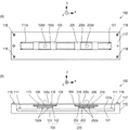
図2(A)は、振動波モータ100を+Z方向から見た平面図であり、図2(B)は、−Y方向から見た正面図である。振動波モータ100は、二つの圧電素子103、203に交流電圧を印加して、圧電素子103、203が発生する超音波領域の周波数の振動(超音波振動)を利用して駆動力を得る構成となっている。   2A is a plan view of the vibration wave motor 100 viewed from the + Z direction, and FIG. 2B is a front view viewed from the −Y direction. The vibration wave motor 100 is configured to apply an AC voltage to the two piezoelectric elements 103 and 203 to obtain a driving force by using vibrations (ultrasonic vibrations) in the ultrasonic region generated by the piezoelectric elements 103 and 203. It has become.

摩擦部材101は、振動子109が加圧接触する接触面101aを備えている。摩擦部材101は、2本の固定ビス111で固定台110に固定されている。本発明の振動波モータ100は、後述の可動部を二つ備えており、それぞれ独立に移動可能な構成となっている。まず初めに第1の可動部について説明する。   The friction member 101 includes a contact surface 101a with which the vibrator 109 is in pressure contact. The friction member 101 is fixed to the fixing base 110 with two fixing screws 111. The vibration wave motor 100 of the present invention includes two movable parts described later, and is configured to be independently movable. First, the first movable part will be described.

振動板102は、接触部102aを備え、接触部102aが押圧を伴う加圧接触状態で接触面101aに接触している。圧電素子103は、振動板102に接着剤などにより圧着されている。そして、振動板102に圧電素子103が圧着された状態で、圧電素子103に電圧を印加すると超音波領域の周波数の振動(超音波振動)が発生する。この超音波振動により、振動板102の接触部102aに楕円運動を発生させることができる。本発明では、振動板102と圧電素子103とによって振動子109が構成されている。   The diaphragm 102 includes a contact portion 102a, and the contact portion 102a is in contact with the contact surface 101a in a pressure contact state with pressing. The piezoelectric element 103 is bonded to the diaphragm 102 with an adhesive or the like. Then, when a voltage is applied to the piezoelectric element 103 in a state where the piezoelectric element 103 is pressure-bonded to the vibration plate 102, vibration of the frequency in the ultrasonic region (ultrasonic vibration) is generated. By this ultrasonic vibration, an elliptical motion can be generated in the contact portion 102a of the diaphragm 102. In the present invention, the vibrator 109 is constituted by the diaphragm 102 and the piezoelectric element 103.

振動子保持部材105は、振動子109周りの部品を保持している。加圧部材106は、不図示の加圧受け部材の貫通穴部に嵌合し、摩擦部材101の接触面101aに対して概ね垂直な方向(Z方向)にのみ移動可能に保持されている。そして振動子保持部材105の中に取り付けられた不図示のバネ部材による押圧力が振動子109に伝えられ、振動子109を摩擦部材101に加圧接触させることができる。   The vibrator holding member 105 holds parts around the vibrator 109. The pressure member 106 is fitted in a through hole portion of a pressure receiving member (not shown), and is held so as to be movable only in a direction (Z direction) substantially perpendicular to the contact surface 101 a of the friction member 101. Then, a pressing force by a spring member (not shown) attached in the vibrator holding member 105 is transmitted to the vibrator 109, and the vibrator 109 can be brought into pressure contact with the friction member 101.

転動ボール116が振動子保持部材105に形成された溝(不図示)と後述する天板117に形成された溝(不図示)との間に介在することにより、振動子保持部材105は、天板117に対して転動支持される。天板117は、4本の固定ビス118により固定台110に固定されている。天板117の中央には、長方形開口117aが形成されており、長方形開口117aから振動子保持部材105の突出部105cが外側に露出している。突出部105cには、球面部105dが設けられている。   The rolling ball 116 is interposed between a groove (not shown) formed in the vibrator holding member 105 and a groove (not shown) formed in the top plate 117 described later, whereby the vibrator holding member 105 is It is supported by rolling with respect to the top plate 117. The top plate 117 is fixed to the fixing base 110 by four fixing screws 118. A rectangular opening 117a is formed at the center of the top plate 117, and the protruding portion 105c of the vibrator holding member 105 is exposed to the outside from the rectangular opening 117a. The protruding portion 105c is provided with a spherical portion 105d.

振動子109の接触部102aに発生した楕円運動により、振動子109が摩擦部材101に対してX方向に相対的に移動する構成において、固定台110、摩擦部材101、固定ビス111、天板117、固定ビス118が固定部となる。一方、振動子109を含めた、加圧部材106、バネ部材(不図示)、そしてそれらを保持する振動子保持部材105が第1の可動部となる。つまり本発明の振動波モータ100は、駆動源である振動子109自身が可動する自走式のモータユニットとなっている。   In the configuration in which the vibrator 109 moves relative to the friction member 101 in the X direction due to the elliptical motion generated in the contact portion 102a of the vibrator 109, the fixed base 110, the friction member 101, the fixing screw 111, and the top plate 117. The fixing screw 118 becomes a fixing portion. On the other hand, the pressure member 106, the spring member (not shown) including the vibrator 109, and the vibrator holding member 105 that holds them serve as the first movable portion. That is, the vibration wave motor 100 according to the present invention is a self-propelled motor unit in which the vibrator 109 itself as a driving source is movable.

本発明の振動波モータ100は、以上説明したような第1の可動部に対し、第2の可動部をもう一つ備える。即ち、一つの摩擦部材101を二つの可動部が兼用している。これら二つの可動部は構成が同じであるため、第2の可動部については部材名称の対応関係だけの説明とする。振動板202は、振動板102に対応する。接触部202aは、接触部102aに対応する。圧電素子203は、圧電素子103に対応する。振動子209は、振動子109に対応する。振動子保持部材205は、振動子保持部材105に対応する。振動子保持部材205の突出部205cは、突出部105cに対応する。加圧部材206は、加圧部材106に対応する。転動ボール216は、転動ボール116に対応する。   The vibration wave motor 100 of the present invention is provided with another second movable part with respect to the first movable part as described above. That is, one movable member 101 is used by two movable parts. Since these two movable parts have the same configuration, only the correspondence between the member names will be described for the second movable part. The diaphragm 202 corresponds to the diaphragm 102. The contact part 202a corresponds to the contact part 102a. The piezoelectric element 203 corresponds to the piezoelectric element 103. The vibrator 209 corresponds to the vibrator 109. The vibrator holding member 205 corresponds to the vibrator holding member 105. The protrusion 205c of the vibrator holding member 205 corresponds to the protrusion 105c. The pressure member 206 corresponds to the pressure member 106. The rolling ball 216 corresponds to the rolling ball 116.

上述の第1の可動部において、振動子保持部材105に設けられた球面部105dが、図1で説明した切り欠き部13cに当接することにより、振動子保持部材105は第1フォーカスレンズL2を保持する保持部材13と連結する。これにより振動波モータ100で第1フォーカスレンズL2をX方向に駆動することが可能となる。第2の可動部も同様に、振動子保持部材205に設けられた球面部205dが、図1で説明した切り欠き部23cに当接することにより、振動子保持部材205は第2フォーカスレンズL3を保持する保持部材23と連結する。これにより振動波モータ100で第2フォーカスレンズL3をX方向に駆動することが可能となる。   In the first movable portion described above, the spherical portion 105d provided on the vibrator holding member 105 abuts on the notch 13c described in FIG. 1, so that the vibrator holding member 105 moves the first focus lens L2. It connects with the holding member 13 to hold | maintain. Accordingly, the first focus lens L2 can be driven in the X direction by the vibration wave motor 100. Similarly, in the second movable portion, the spherical surface portion 205d provided on the vibrator holding member 205 comes into contact with the notch portion 23c described in FIG. 1, so that the vibrator holding member 205 causes the second focus lens L3 to move. It connects with the holding member 23 to hold | maintain. As a result, the second focus lens L3 can be driven in the X direction by the vibration wave motor 100.

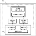
図3は、本発明の駆動装置140の構成を示すブロック図である。振動波モータ100は、振動子109と振動子209とが摩擦部材101に摩擦接触する形態として構成されており、位置検出手段16は振動子109の位置を検出し、位置検出手段26は振動子209の位置を検出する。間隔算出手段141は、位置検出手段16で検出された振動子109の位置と位置検出手段26で検出された振動子209の位置を取得し、振動子109と振動子209の間隔を算出する。   FIG. 3 is a block diagram showing the configuration of the driving device 140 of the present invention. The vibration wave motor 100 is configured such that the vibrator 109 and the vibrator 209 are in frictional contact with the friction member 101, the position detecting unit 16 detects the position of the vibrator 109, and the position detecting unit 26 is the vibrator. The position of 209 is detected. The interval calculation unit 141 obtains the position of the transducer 109 detected by the position detection unit 16 and the position of the transducer 209 detected by the position detection unit 26, and calculates the interval between the transducer 109 and the transducer 209.

位相差制御手段142は、摩擦部材101に共振により発生する振動が軽減されるように、間隔算出手段141で算出した間隔に基づいて、振動子109と振動子209に入力する駆動信号出力の位相差を設定する。間隔算出手段141と位相差制御手段142とは、演算処理部10が担っている。本発明の駆動装置140は、振動波モータ100、位置検出手段16、位置検出手段26、間隔算出手段141、及び位相差制御手段142により構成されている。摩擦部材101に共振により発生する振動を軽減させるメカニズム及び位相差の算出方法については、図4乃至図9を用いて説明する。   The phase difference control unit 142 determines the level of the drive signal output input to the vibrator 109 and the vibrator 209 based on the interval calculated by the interval calculation unit 141 so that vibration generated by resonance in the friction member 101 is reduced. Set the phase difference. The calculation processing unit 10 is responsible for the interval calculation unit 141 and the phase difference control unit 142. The drive device 140 according to the present invention includes the vibration wave motor 100, the position detection unit 16, the position detection unit 26, the interval calculation unit 141, and the phase difference control unit 142. A mechanism for reducing vibration generated by resonance in the friction member 101 and a method for calculating the phase difference will be described with reference to FIGS.

図4(A)乃至(C)は、従来の形態において、振動子109と振動子209とにより摩擦部材101に発生する共振による振動が重畳して大きな振幅319となる状態を、−Y方向から見た図として示している。図4(A)乃至(C)では、同位相で超音波振動している二つの振動子109、振動子209の間隔Lが摩擦部材101の固有振動の波長λの整数倍nλの長さになっている。   4A to 4C illustrate a state in which vibrations due to resonance generated in the friction member 101 by the vibrator 109 and the vibrator 209 are superimposed to obtain a large amplitude 319 in the conventional form from the −Y direction. It is shown as a view. 4A to 4C, the distance L between the two vibrators 109 and 209 that are ultrasonically oscillated in the same phase is a length of an integral multiple nλ of the wavelength λ of the natural vibration of the friction member 101. It has become.

図4(A)は、振動子109によって摩擦部材101に共振により発生する振動を示している。振動子109に励起される超音波振動により摩擦部材101が加振されると、摩擦部材101の固有振動のうち、振動子109の超音波振動の周波数に近いものが励起され、摩擦部材101は共振する。この摩擦部材101の固有振動の波長をλとする。振動子109によって摩擦部材101には、振幅119の振動が発生する。   FIG. 4A shows vibration generated by resonance in the friction member 101 by the vibrator 109. When the friction member 101 is vibrated by the ultrasonic vibration excited by the vibrator 109, the natural vibration of the friction member 101 that is close to the frequency of the ultrasonic vibration of the vibrator 109 is excited. Resonates. The wavelength of the natural vibration of the friction member 101 is λ. The vibrator 109 generates a vibration having an amplitude 119 in the friction member 101.

図4(B)は、振動子109から間隔Lだけ離れた位置にある振動子209によって摩擦部材101に共振により発生する振動を示している。間隔Lは、摩擦部材101の固有振動の波長λの整数倍nλの長さになっている。振動子209に励起される超音波振動により摩擦部材101が加振されると、摩擦部材101の固有振動のうち、振動子209の超音波振動の周波数に近いものが励起され、摩擦部材101は共振する。振動子209によって摩擦部材101には、振幅219の振動が発生する。この際、振動子109と振動子209との間隔Lは、摩擦部材101の固有振動の波長λの整数倍nλの長さになっている。そのため、振動子109によって励起される摩擦部材101の共振の位相と、振動子209によって励起される摩擦部材101の共振の位相とは、同位相となる。   FIG. 4B shows vibration generated by resonance in the friction member 101 by the vibrator 209 located at a distance L from the vibrator 109. The interval L is a length of an integral multiple nλ of the wavelength λ of the natural vibration of the friction member 101. When the friction member 101 is vibrated by the ultrasonic vibration excited by the vibrator 209, the natural vibration of the friction member 101 that is close to the frequency of the ultrasonic vibration of the vibrator 209 is excited, and the friction member 101 Resonates. The vibration 209 generates vibration with an amplitude 219 in the friction member 101. At this time, the distance L between the vibrator 109 and the vibrator 209 is a length of an integral multiple nλ of the wavelength λ of the natural vibration of the friction member 101. Therefore, the phase of resonance of the friction member 101 excited by the vibrator 109 and the phase of resonance of the friction member 101 excited by the vibrator 209 are the same phase.

図4(C)は、振動子109によって励起される摩擦部材101の共振による振動と、振動子209によって励起される摩擦部材101の共振による振動とが重畳している様子を示している。上述のように、同位相で超音波振動している振動子同士の間隔Lが、摩擦部材101の固有振動の波長λの整数倍nλの長さになっている場合、振動子109による共振の位相と、振動子209による共振の位相とは同位相となる。そして、振動子109による摩擦部材101の振動の振幅119と、振動子209による摩擦部材101の振動の振幅219とは、同程度であり、これらの振動が重畳した際、振幅119と振幅219とを重ね合わせた大きな振幅319となる。   FIG. 4C shows a state in which vibration due to resonance of the friction member 101 excited by the vibrator 109 and vibration due to resonance of the friction member 101 excited by the vibrator 209 are superimposed. As described above, when the distance L between the vibrators that are ultrasonically oscillated in the same phase is a length that is an integral multiple nλ of the wavelength λ of the natural vibration of the friction member 101, The phase and the phase of resonance by the vibrator 209 are the same phase. The amplitude 119 of the vibration of the friction member 101 by the vibrator 109 and the amplitude 219 of the vibration of the friction member 101 by the vibrator 209 are approximately the same, and when these vibrations are superimposed, the amplitude 119 and the amplitude 219 Becomes a large amplitude 319.

図4(A)乃至(C)では、振動子109、振動子209が同位相で超音波振動している場合であるが、摩擦部材101に励起される振動が重畳して大きくなるのは、この同位相の場合だけではない。例えば、逆位相で超音波振動している二つの振動子109、振動子209の間隔Lが摩擦部材101の固有振動の波長λの(整数+0.5)倍の場合でも振動が重畳して振幅319が大きくなり、またその間の位置においても振幅319が大きくなる。このように従来の形態では、二つの振動子109、振動子209の超音波振動の位相差とその間隔Lとにより、摩擦部材101に発生する振動が重畳して大きな振動になってしまうという問題があった。   4A to 4C show a case where the vibrator 109 and the vibrator 209 are ultrasonically vibrated in the same phase, and the vibration excited by the friction member 101 is superimposed and becomes large. This is not the only case. For example, even when the distance L between the two vibrators 109 and 209 that are ultrasonically vibrated in opposite phases is (integer +0.5) times the wavelength λ of the natural vibration of the friction member 101, the vibration is superimposed and the amplitude is increased. 319 is increased, and the amplitude 319 is also increased at a position in between. As described above, in the conventional form, the vibration generated in the friction member 101 is superposed due to the phase difference between the ultrasonic vibrations of the two vibrators 109 and 209 and the interval L, resulting in a large vibration. was there.

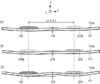
図5(A)乃至(C)は、本発明の駆動装置140において、振動子109と振動子209とによる振動が重畳して打ち消し合う状態を−Y方向から見た図として示している。なお、二つの振動子109、振動子209の間隔Lは、摩擦部材101の固有振動の波長λの整数倍nλの長さになっている。   FIGS. 5A to 5C show, as viewed from the −Y direction, a state in which the vibrations of the vibrator 109 and the vibrator 209 overlap and cancel each other in the driving device 140 of the present invention. The distance L between the two vibrators 109 and 209 is a length that is an integral multiple nλ of the wavelength λ of the natural vibration of the friction member 101.

図5(A)は、振動子109によって摩擦部材101に共振により発生する振動を示している。振動子109に励起される超音波振動により摩擦部材101が加振されると、摩擦部材101の固有振動のうち、振動子109の超音波振動の周波数に近いものが励起され、摩擦部材101は共振する。振動子109によって摩擦部材101には、振幅120の振動が発生する。   FIG. 5A shows vibration generated by resonance in the friction member 101 by the vibrator 109. When the friction member 101 is vibrated by the ultrasonic vibration excited by the vibrator 109, the natural vibration of the friction member 101 that is close to the frequency of the ultrasonic vibration of the vibrator 109 is excited. Resonates. A vibration with an amplitude of 120 is generated in the friction member 101 by the vibrator 109.

図5(B)は、振動子109から間隔Lだけ離れた位置にある振動子209によって摩擦部材101に共振により発生する振動を示している。本発明の駆動装置140では、間隔Lの長さに応じて、振動子109と振動子209とにおける超音波振動の位相差を変えている。例えば、間隔Lが摩擦部材101の固有振動の波長λの整数倍nλの長さとなる場合には、振動子109と振動子209の超音波振動の位相を逆位相とする。振動子109に対して逆位相で超音波振動する振動子209によって、摩擦部材101には振動子109によって共振で発生した振動とは逆位相の振動が発生する。振動子209によって摩擦部材101に共振により発生する振動の振幅220が示されている。   FIG. 5B shows vibration generated by resonance in the friction member 101 by the vibrator 209 located at a distance L from the vibrator 109. In the driving device 140 of the present invention, the phase difference of the ultrasonic vibration between the vibrator 109 and the vibrator 209 is changed according to the length of the interval L. For example, when the interval L is a length that is an integral multiple nλ of the wavelength λ of the natural vibration of the friction member 101, the phases of the ultrasonic vibrations of the vibrator 109 and the vibrator 209 are reversed. By the vibrator 209 that vibrates ultrasonically in the opposite phase with respect to the vibrator 109, the friction member 101 generates vibration having a phase opposite to that generated by resonance by the vibrator 109. An amplitude 220 of vibration generated by resonance in the friction member 101 by the vibrator 209 is shown.

図5(C)は、振動子109によって励起される摩擦部材101の共振による振動と、振動子209によって励起される摩擦部材101の共振による振動とが重畳して打ち消し合っている様子を示している。逆位相で超音波振動している振動子同士の間隔Lが摩擦部材101の固有振動の波長λの整数倍nλの長さの場合、振動子109によって励起される摩擦部材101の共振の位相と、振動子209によって励起される摩擦部材101の共振の位相は、逆位相になる。そのため、図5(C)に示すように二つの振動は、重畳することにより打ち消し合い、小さな振幅320の振動となる。また、振動子109によって励起される摩擦部材101の振動の振幅120と振動子209によって励起される摩擦部材101の振動の振幅220は、ほぼ同程度の大きさであり、二つの振動は逆位相の振動である。そのため、二つの振動が互いに打ち消し合った際は、振幅120と振幅220の差分程度の非常に小さな振幅320となる。これにより摩擦部材101に発生する振動を低減することができる。   FIG. 5C shows a state where the vibration due to the resonance of the friction member 101 excited by the vibrator 109 and the vibration due to the resonance of the friction member 101 excited by the vibrator 209 are superimposed and cancel each other. Yes. When the interval L between the vibrators that are ultrasonically oscillated in the opposite phase is a length that is an integral multiple nλ of the wavelength λ of the natural vibration of the friction member 101, the resonance phase of the friction member 101 excited by the vibrator 109 The phase of resonance of the friction member 101 excited by the vibrator 209 is opposite to the phase. For this reason, as shown in FIG. 5C, the two vibrations cancel each other out by being superposed, resulting in a vibration with a small amplitude 320. In addition, the amplitude 120 of the vibration of the friction member 101 excited by the vibrator 109 and the amplitude 220 of the vibration of the friction member 101 excited by the vibrator 209 are approximately the same magnitude, and the two vibrations have opposite phases. Vibration. Therefore, when the two vibrations cancel each other, the amplitude 320 becomes very small, which is about the difference between the amplitude 120 and the amplitude 220. Thereby, the vibration generated in the friction member 101 can be reduced.

図6(A)は、振動子109の接触部102aに発生させる楕円振動130を示しており、図6(B)は、振動子209の接触部202aに発生させる楕円振動230を示している。いずれの場合も振動子109と振動子209の間隔Lは、摩擦部材101の固有振動の波長λの整数倍nλの長さとなっている。   6A shows the elliptical vibration 130 generated at the contact portion 102a of the vibrator 109, and FIG. 6B shows the elliptical vibration 230 generated at the contact portion 202a of the vibrator 209. In any case, the distance L between the vibrator 109 and the vibrator 209 is a length of an integral multiple nλ of the wavelength λ of the natural vibration of the friction member 101.

図6(A)には、振動子109の接触部102aの楕円振動130が1周期する間に接触部102aは、位置(1)→(2)→(3)→(4)の順番に移動することが示されている。一方、図6(B)には、振動子209の接触部202aの楕円振動230が1周期する間に接触部202aは、位置(1)→(2)→(3)→(4)の順番に移動することが示されている。楕円振動130の(1)と楕円振動230の(1)、楕円振動130の(2)と楕円振動230の(2)、楕円振動130の(3)と楕円振動230の(3)、楕円振動130の(4)と楕円振動230の(4)は、同じ時刻におけるそれぞれの位置を表している。楕円振動130の位相をθ130、楕円振動230の位相をθ230、楕円振動130と楕円振動230の位相差をΔθとすると、位相差Δθがπ(180°)となるように振動子109と振動子209を振動させる。このような位相差Δθにより、摩擦部材101に発生する振動を互いに打ち消し合うことができる。 In FIG. 6A, the contact portion 102a moves in the order of position (1) → (2) → (3) → (4) while the elliptical vibration 130 of the contact portion 102a of the vibrator 109 makes one cycle. Has been shown to do. On the other hand, in FIG. 6B, while the elliptical vibration 230 of the contact portion 202a of the vibrator 209 makes one cycle, the contact portion 202a moves in the order of position (1) → (2) → (3) → (4). Has been shown to move on. (1) of elliptical vibration 130 and (1) of elliptical vibration 230, (2) of elliptical vibration 130 and (2) of elliptical vibration 230, (3) of elliptical vibration 130 and (3) of elliptical vibration 230, elliptical vibration (4) of 130 and (4) of elliptical vibration 230 represent the respective positions at the same time. When the phase of the elliptical vibration 130 is θ 130 , the phase of the elliptical vibration 230 is θ 230 , and the phase difference between the elliptical vibration 130 and the elliptical vibration 230 is Δθ, the phase difference Δθ is π (180 °). The vibrator 209 is vibrated. With such a phase difference Δθ, vibrations generated in the friction member 101 can be canceled with each other.

図7(A)乃至(C)は、本発明の駆動装置140において、振動子109と振動子209とによる振動が重畳して打ち消し合う状態を−Y方向から見た図として示している。なお、二つの振動子109、振動子209の間隔Lは、摩擦部材101の固有振動の波長λの(整数n+0.5)倍の長さとなっている。   FIGS. 7A to 7C show a state in which the vibrations of the vibrator 109 and the vibrator 209 overlap and cancel each other in the driving device 140 of the present invention as seen from the −Y direction. The interval L between the two vibrators 109 and 209 is a length (integer n + 0.5) times the wavelength λ of the natural vibration of the friction member 101.

図7(A)は、振動子109によって摩擦部材101に共振により発生する振動を示している。振動子109に励起される超音波振動により摩擦部材101が加振されると、摩擦部材101の固有振動のうち、振動子109の超音波振動の周波数に近いものが励起され、摩擦部材101は共振する。振動子109によって摩擦部材101には、振幅121の振動が発生する。   FIG. 7A shows vibration generated by resonance in the friction member 101 by the vibrator 109. When the friction member 101 is vibrated by the ultrasonic vibration excited by the vibrator 109, the natural vibration of the friction member 101 that is close to the frequency of the ultrasonic vibration of the vibrator 109 is excited. Resonates. The vibration 109 generates vibration with an amplitude 121 in the friction member 101.

図7(B)は、振動子109から間隔Lだけ離れた位置にある振動子209によって摩擦部材101に共振により発生する振動を示している。本発明の駆動装置140では、間隔Lの長さに応じて、振動子109と振動子209の超音波振動の位相差Δθを変えている。例えば、間隔Lが摩擦部材101の固有振動の波長λの(整数n+0.5)倍の長さとなる距離の場合には、振動子109と振動子209の超音波振動の位相を同位相とする。振動子109と同位相で超音波振動する振動子209によって、摩擦部材101には振動子109で励起された振動とは逆位相の振動が発生する。振動子209によって摩擦部材101に発生する振動の振幅221が示されている。   FIG. 7B shows vibration generated by resonance in the friction member 101 by the vibrator 209 located at a distance L from the vibrator 109. In the driving device 140 of the present invention, the phase difference Δθ of ultrasonic vibration between the vibrator 109 and the vibrator 209 is changed according to the length of the interval L. For example, when the distance L is a distance that is (integer n + 0.5) times the wavelength λ of the natural vibration of the friction member 101, the phases of the ultrasonic vibrations of the vibrator 109 and the vibrator 209 are the same. . Due to the vibrator 209 that vibrates ultrasonically in the same phase as that of the vibrator 109, a vibration having a phase opposite to that of the vibration excited by the vibrator 109 is generated in the friction member 101. An amplitude 221 of vibration generated in the friction member 101 by the vibrator 209 is shown.

図7(C)は、振動子109によって励起される摩擦部材101の共振による振動と、振動子209によって励起される摩擦部材101の共振による振動とが重畳して打ち消し合っている様子を示している。同位相で超音波振動している振動子同士の間隔Lが摩擦部材101の固有振動の波長λの(整数n+0.5)倍の長さとなる場合、振動子109による摩擦部材101の共振の位相と、振動子209による摩擦部材101の共振の位相とは、逆位相になる。そのため、図7(C)に示すように二つの振動は、重畳することにより打ち消し合い、小さな振幅321の振動となる。また、振動子109によって励起される摩擦部材101の振動の振幅121と振動子209によって励起される摩擦部材101の振動の振幅221は、ほぼ同程度の大きさであり、二つの振動は逆位相の振動である。そのため、二つの振動が互いに打ち消し合った際は、振幅121と振幅221の差分程度の非常に小さな振幅321となる。これにより摩擦部材101に発生する振動を低減することができる。   FIG. 7C shows a state where the vibration due to the resonance of the friction member 101 excited by the vibrator 109 and the vibration due to the resonance of the friction member 101 excited by the vibrator 209 are superimposed and cancel each other. Yes. When the interval L between the vibrators ultrasonically oscillating in the same phase is a length (integer n + 0.5) times the wavelength λ of the natural vibration of the friction member 101, the phase of resonance of the friction member 101 by the vibrator 109 The phase of resonance of the friction member 101 by the vibrator 209 is opposite to the phase. For this reason, as shown in FIG. 7C, the two vibrations cancel each other out by being superposed, resulting in a vibration having a small amplitude 321. Further, the amplitude 121 of the vibration of the friction member 101 excited by the vibrator 109 and the amplitude 221 of the vibration of the friction member 101 excited by the vibrator 209 are approximately the same magnitude, and the two vibrations are in antiphase. Vibration. Therefore, when the two vibrations cancel each other, the amplitude 321 becomes very small, which is about the difference between the amplitude 121 and the amplitude 221. Thereby, the vibration generated in the friction member 101 can be reduced.

図8(A)は、振動子109の接触部102aに発生させる楕円振動130を示しており、図8(B)は、振動子209の接触部202aに発生させる楕円振動230を示している。いずれの場合も振動子109と振動子209の間隔Lは、摩擦部材101の固有振動の波長λの(整数n+0.5)倍の長さとなっている。   8A shows the elliptical vibration 130 generated at the contact portion 102a of the vibrator 109, and FIG. 8B shows the elliptical vibration 230 generated at the contact portion 202a of the vibrator 209. In any case, the distance L between the vibrator 109 and the vibrator 209 is a length (integer n + 0.5) times the wavelength λ of the natural vibration of the friction member 101.

図8(A)には、振動子109の接触部102aの楕円振動130が1周期する間に接触部102aは、位置(1)→(2)→(3)→(4)の順番に移動することが示されている。一方、図8(B)には、振動子209の接触部202aの楕円振動230が1周期する間に接触部202aは、位置(1)→(2)→(3)→(4)の順番に移動することが示されている。楕円振動130の(1)と楕円振動230の(1)、楕円振動130の(2)と楕円振動230の(2)、楕円振動130の(3)と楕円振動230の(3)、楕円振動130の(4)と楕円振動230の(4)は、同じ時刻におけるそれぞれの位置を表している。楕円振動130の位相をθ130、楕円振動230の位相をθ230、楕円振動130と楕円振動230の位相差をΔθとすると、位相差Δθが0°となるように振動子109と振動子209を振動させる。このような位相差Δθにより、摩擦部材101に発生する振動を互いに打ち消し合うことができる。 In FIG. 8A, the contact portion 102a moves in the order of position (1) → (2) → (3) → (4) while the elliptical vibration 130 of the contact portion 102a of the vibrator 109 makes one cycle. Has been shown to do. On the other hand, in FIG. 8B, while the elliptical vibration 230 of the contact portion 202a of the vibrator 209 makes one cycle, the contact portion 202a moves in the order of position (1) → (2) → (3) → (4). Has been shown to move on. (1) of elliptical vibration 130 and (1) of elliptical vibration 230, (2) of elliptical vibration 130 and (2) of elliptical vibration 230, (3) of elliptical vibration 130 and (3) of elliptical vibration 230, elliptical vibration (4) of 130 and (4) of elliptical vibration 230 represent the respective positions at the same time. When the phase of the elliptical vibration 130 is θ 130 , the phase of the elliptical vibration 230 is θ 230 , and the phase difference between the elliptical vibration 130 and the elliptical vibration 230 is Δθ, the vibrator 109 and the vibrator 209 so that the phase difference Δθ is 0 °. Vibrate. With such a phase difference Δθ, vibrations generated in the friction member 101 can be canceled with each other.

図5(C)、図6(A)及び(B)において、二つの振動子109、振動子209の間隔Lが摩擦部材101の固有振動の波長λの整数倍nλとなる場合を説明した。図7(C)、図8(A)及び(B)において、二つの振動子109、振動子209の間隔Lが摩擦部材101の固有振動の波長λの(整数n+0.5)倍となる場合を説明した。間隔Lが固有振動の波長λの整数倍nλと(整数n+0.5)倍の間にあるときにも、内挿補間して二つの振動子109、振動子209の位相差Δθを算出することで、摩擦部材101に発生する振動を低減することができる。   5C, 6A, and 6B, the case where the distance L between the two vibrators 109 and 209 is an integral multiple nλ of the wavelength λ of the natural vibration of the friction member 101 has been described. 7C, 8A, and 8B, the distance L between the two vibrators 109 and 209 is (integer n + 0.5) times the wavelength λ of the natural vibration of the friction member 101. Explained. Even when the interval L is between the integer multiple nλ and (integer n + 0.5) times the wavelength λ of the natural vibration, the phase difference Δθ between the two vibrators 109 and 209 is calculated by interpolation. Thus, vibration generated in the friction member 101 can be reduced.

次に、二つの振動子109、振動子209の間隔Lを以下の式(I)で表わす。
L=nλ+aλ n:整数 a:0から1までの小数 ・・・(I)
このとき、二つの振動子109、振動子209に発生させる振動の位相差Δθは、以下の式(II)で表わされる。
Δθ=(1−2a)π ・・・(II)
図5(C)の状態においては、a=0、図7(C)の状態においては、a=0.5となる。
Next, the distance L between the two vibrators 109 and 209 is expressed by the following formula (I).
L = nλ + aλ n: integer a: decimal number from 0 to 1 (I)
At this time, the phase difference Δθ of vibrations generated in the two vibrators 109 and 209 is expressed by the following formula (II).
Δθ = (1-2a) π (II)
In the state of FIG. 5C, a = 0, and in the state of FIG. 7C, a = 0.5.

以上のように、同一の摩擦部材101に摩擦接触する二つの振動子109、振動子209の間隔Lが式(I)で表わされる場合は、二つの振動子109、振動子209に発生する振動の位相差Δθを式(II)のように設定する。そうすることで、摩擦部材101に発生する振動を低減することができる。   As described above, when the distance L between the two vibrators 109 and 209 that are in frictional contact with the same friction member 101 is expressed by the formula (I), the vibration generated in the two vibrators 109 and 209 Is set as shown in Equation (II). By doing so, vibration generated in the friction member 101 can be reduced.

図9は、本発明の駆動装置140の動作フローチャートである。本発明の駆動装置140の駆動開始から駆動終了までの動作が示されている。   FIG. 9 is an operation flowchart of the driving device 140 of the present invention. The operation from the driving start to the driving end of the driving device 140 of the present invention is shown.

ステップS01では、演算処理部10が振動子109の目標位置と振動子209の目標位置をそれぞれ設定する。   In step S01, the arithmetic processing unit 10 sets the target position of the vibrator 109 and the target position of the vibrator 209, respectively.

ステップS02では、位置検出手段16が振動子109の位置を検出する。ステップS03では、位置検出手段26が振動子209の位置を検出する。   In step S02, the position detection unit 16 detects the position of the vibrator 109. In step S03, the position detector 26 detects the position of the vibrator 209.

ステップS04では、ステップS02で検出した振動子109の位置とステップS03で検出した振動子209の位置とにより、振動子109と振動子209とがステップS01で設定した目標位置に対して所定距離の範囲内にあるか否か判定する。ここで所定距離は、許容錯乱円、レンズ装置1の口径比、レンズ装置1のフォーカス敏感度から決まる値であり、目標位置からずれても撮影系として問題とならない距離を設定する。   In step S04, the vibrator 109 and the vibrator 209 have a predetermined distance from the target position set in step S01 by the position of the vibrator 109 detected in step S02 and the position of the vibrator 209 detected in step S03. It is determined whether it is within the range. Here, the predetermined distance is a value determined from the permissible circle of confusion, the aperture ratio of the lens apparatus 1 and the focus sensitivity of the lens apparatus 1, and is set to a distance that does not cause a problem as a photographing system even if it deviates from the target position.

ステップS04において、振動子109と振動子209とが目標位置から所定距離の範囲内にあると判定された場合には、駆動を行わずそのまま動作フローを終了する。目標位置から所定距離の範囲内にないと判定された場合には、ステップS05に進む。   If it is determined in step S04 that the vibrator 109 and the vibrator 209 are within a predetermined distance from the target position, the operation flow is ended without performing driving. If it is determined that the distance is not within the predetermined distance from the target position, the process proceeds to step S05.

ステップS05では、ステップS02で検出した振動子109の位置とステップS01で設定した目標位置との偏差を算出する。更に、ステップS03で検出した振動子209の位置とステップS01で設定した目標位置との偏差も算出する。   In step S05, a deviation between the position of the vibrator 109 detected in step S02 and the target position set in step S01 is calculated. Further, the deviation between the position of the vibrator 209 detected in step S03 and the target position set in step S01 is also calculated.

ステップS06では、ステップS05で算出したそれぞれの偏差に基づいて、振動子109の駆動パターンを設定する指令値と、振動子209の駆動パターンを設定する指令値とをそれぞれ設定する。   In step S06, a command value for setting the drive pattern of the vibrator 109 and a command value for setting the drive pattern of the vibrator 209 are set based on the respective deviations calculated in step S05.

ステップS07では、ステップS02で検出した振動子109の位置とステップS03で検出した振動子209の位置とに基づいて、振動子109と振動子209の間隔Lを算出する。この動作は、間隔算出手段141が行う。   In step S07, the distance L between the transducer 109 and the transducer 209 is calculated based on the position of the transducer 109 detected in step S02 and the position of the transducer 209 detected in step S03. This operation is performed by the interval calculation means 141.

ステップS08では、ステップS07で算出した間隔Lに基づいて、図5乃至図8で説明したように、摩擦部材101で発生する振動が打ち消されるように、振動子109の楕円振動130と振動子209の楕円振動230の位相差Δθを設定する。この動作は、位相差制御手段142が行う。   In step S08, based on the interval L calculated in step S07, the elliptical vibration 130 and the vibrator 209 of the vibrator 109 are canceled so that the vibration generated in the friction member 101 is canceled as described in FIGS. The phase difference Δθ of the elliptical vibration 230 is set. This operation is performed by the phase difference control means 142.

ステップS09では、ステップS06で設定した振動子109の駆動パターンを設定する指令値に基づいて、振動子109に入力する駆動信号を出力する。   In step S09, a drive signal to be input to the vibrator 109 is output based on the command value for setting the drive pattern of the vibrator 109 set in step S06.

ステップS10では、ステップS06で設定した振動子209の駆動パターンを設定する指令値に基づいて、振動子209に入力する駆動信号を出力する。この際、振動子109の楕円振動130と振動子209の楕円振動230の位相差Δθが、ステップS08で設定した値になるように、振動子109に入力する駆動信号と振動子209に入力する駆動信号とを所定量の位相差Δθで出力する。ステップS10が終わると、ステップS02に戻る。   In step S10, the drive signal input to the vibrator 209 is output based on the command value for setting the drive pattern of the vibrator 209 set in step S06. At this time, the drive signal input to the vibrator 109 and the vibrator 209 are input so that the phase difference Δθ between the elliptical vibration 130 of the vibrator 109 and the elliptical vibration 230 of the vibrator 209 becomes the value set in step S08. The drive signal is output with a predetermined amount of phase difference Δθ. When step S10 ends, the process returns to step S02.

以上のように、複数の振動子によって摩擦部材101に発生する振動が互いに打ち消し合うように、複数の振動子の間隔Lに応じて複数の振動子の振動の位相差Δθを変えることで、摩擦部材に発生する振動を低減した振動波モータを実現することができる。以上、本発明の好ましい実施例について説明したが、本発明はこれらの実施例に限定されず、その要旨の範囲内で種々の変形及び変更が可能である。   As described above, by changing the phase difference Δθ of the vibrations of the plurality of vibrators according to the interval L of the plurality of vibrators so that the vibrations generated in the friction member 101 by the plurality of vibrators cancel each other, A vibration wave motor with reduced vibration generated in the member can be realized. As mentioned above, although the preferable Example of this invention was described, this invention is not limited to these Examples, A various deformation | transformation and change are possible within the range of the summary.

16、26 位置検出手段
101 摩擦部材
101a 接触面
102、202 振動板
103、203 圧電素子
109、209 振動子
102a、202a 接触部
130、230 楕円振動
140 駆動装置
141 間隔算出手段
142 位相差制御手段
L 間隔
Δθ 楕円振動130と楕円振動230の位相差
λ 波長
n 整数
16, 26 Position detection means 101 Friction member 101a Contact surface 102, 202 Diaphragm 103, 203 Piezoelectric element 109, 209 Vibrator 102a, 202a Contact portion 130, 230 Elliptical vibration 140 Drive device 141 Distance calculation means 142 Phase difference control means L Distance Δθ Phase difference between elliptical vibration 130 and elliptical vibration 230 λ wavelength n integer

Claims (5)

少なくとも一つの接触部を備える振動板と圧電素子とを固着して構成される、複数の振動子と、
前記接触部と摩擦接触する接触面を有する摩擦部材と、を備え、
前記摩擦部材には、複数の前記振動子が加圧接触し、
複数の前記振動子は、前記圧電素子で励起される振動で前記接触部に楕円振動を発生し、
前記楕円振動によって複数の前記振動子と前記摩擦部材とは相対的に移動する駆動装置において、
複数の前記振動子の間隔に応じて、前記圧電素子で励起される複数の前記振動子のそれぞれの振動の位相を制御する制御手段を有することを特徴とする、駆動装置。
A plurality of vibrators configured by adhering a diaphragm including at least one contact portion and a piezoelectric element;
A friction member having a contact surface in frictional contact with the contact portion,
A plurality of the vibrators are in pressure contact with the friction member,
The plurality of vibrators generate elliptical vibrations in the contact portion by vibrations excited by the piezoelectric elements,
In the drive device in which the plurality of vibrators and the friction member move relatively by the elliptical vibration,
A drive device comprising control means for controlling a phase of vibration of each of the plurality of vibrators excited by the piezoelectric element in accordance with an interval between the plurality of vibrators.
前記制御手段は、複数の前記振動子の間隔に応じて、複数の前記振動子のそれぞれの振動の位相の差である位相差を変更することを特徴とする、請求項に記載の駆動装置。 2. The driving apparatus according to claim 1 , wherein the control unit changes a phase difference, which is a difference in phase between vibrations of the plurality of vibrators, according to an interval between the plurality of vibrators. . 複数の前記振動子は、それぞれ独立に移動し、
複数の前記振動子の位置をそれぞれ検出する複数の位置検出手段と、
該位置検出手段で検出された複数の前記振動子の位置に基づいて前記間隔を算出する間隔算出手段と、を有することを特徴とする、請求項に記載の駆動装置。
The plurality of vibrators move independently of each other,
A plurality of position detecting means for respectively detecting the positions of the plurality of vibrators;
The drive device according to claim 2 , further comprising: an interval calculation unit that calculates the interval based on the positions of the plurality of vibrators detected by the position detection unit.
前記制御手段は、前記間隔が前記摩擦部材の固有振動の波長の整数倍の場合は、前記位相差を180°とし、前記間隔が前記摩擦部材の固有振動の波長の(整数+0.5)倍の場合は、前記位相差を0°とし、前記間隔が整数倍と(整数+0.5)倍の間の場合は、前記位相差を内挿補間して求めた値とすることを特徴とする、請求項に記載の駆動装置。 When the interval is an integer multiple of the natural vibration wavelength of the friction member, the control means sets the phase difference to 180 °, and the interval is (integer +0.5) times the natural vibration wavelength of the friction member. In this case, the phase difference is set to 0 °, and when the interval is between an integer multiple and (integer +0.5) times, the phase difference is a value obtained by interpolation. The drive device according to claim 3 . 前記振動は、超音波領域の周波数の超音波振動であることを特徴とする、請求項1乃至のいずれか1項に記載の駆動装置。 The vibration is characterized by a ultrasonic vibration at a frequency in the ultrasonic range, driving apparatus according to any one of claims 1 to 4.
JP2015174459A 2015-09-04 2015-09-04 Drive device Expired - Fee Related JP6557559B2 (en)

Priority Applications (1)

Application Number Priority Date Filing Date Title
JP2015174459A JP6557559B2 (en) 2015-09-04 2015-09-04 Drive device

Applications Claiming Priority (1)

Application Number Priority Date Filing Date Title
JP2015174459A JP6557559B2 (en) 2015-09-04 2015-09-04 Drive device

Publications (3)

Publication Number Publication Date
JP2017051041A JP2017051041A (en) 2017-03-09
JP2017051041A5 JP2017051041A5 (en) 2018-10-11
JP6557559B2 true JP6557559B2 (en) 2019-08-07

Family

ID=58278337

Family Applications (1)

Application Number Title Priority Date Filing Date
JP2015174459A Expired - Fee Related JP6557559B2 (en) 2015-09-04 2015-09-04 Drive device

Country Status (1)

Country Link
JP (1) JP6557559B2 (en)

Families Citing this family (1)

* Cited by examiner, † Cited by third party
Publication number Priority date Publication date Assignee Title
JP7397302B2 (en) * 2019-12-26 2023-12-13 ミツミ電機株式会社 Lens drive device, camera module and camera mounting device

Also Published As

Publication number Publication date
JP2017051041A (en) 2017-03-09

Similar Documents

Publication Publication Date Title
JP5064864B2 (en) Optical deflection apparatus, image forming apparatus, and driving method of optical deflection apparatus
JP2007312465A (en) Drive unit, optical scanning device, and substance information detection device
JP2007170938A (en) Encoder
EP3382884B1 (en) Vibration wave motor and optical device
JP5065116B2 (en) Oscillator device, optical deflection device, and control method thereof
JP6557559B2 (en) Drive device
US20220065892A1 (en) Laser Interferometer and Control Method for Laser Interferometer
JP2009058616A (en) Oscillating body apparatus, light deflector and image forming apparatus using the same
JP2570237B2 (en) Optical scanner, vibrating device, optical device, and optical beam printer
JP2019103371A (en) Vibration wave motor and lens driving apparatus using vibration wave motor
JP2008299297A (en) Rocking body apparatus and method of driving and controlling oscillation system of rocking body apparatus
JP4976885B2 (en) Lens barrel turning mechanism
JP6529279B2 (en) Vibration type drive device, lens barrel and imaging device
JP6957322B2 (en) Vibration type motors, lens devices, and electronic devices
JP6188446B2 (en) Optical member driving device and lens device having the same
JPH07270879A (en) Camera provided with actuator and camera system
JPH04368907A (en) Optical scanner
JP5339109B2 (en) Rotary encoder
JP6369357B2 (en) Scanning device
JP2019109351A (en) Optical scanning device
JP2020072558A (en) Vibration wave motor and drive unit provided with the vibration wave motor
JP2021016271A (en) Drive device using vibration body and method for controlling the same
JP5296425B2 (en) OPTICAL SCANNING DEVICE, PRINTING DEVICE USING THE SAME, CONTROL METHOD THEREOF, DISPLAY DEVICE EQUIPPED WITH OPTICAL SCANNING DEVICE, IMAGE READING DEVICE, AND BARCODE READER
JP2017108496A (en) Vibration wave motor and lens apparatus including the same
JP2008112783A (en) System and method for irradiating light

Legal Events

Date Code Title Description
RD05 Notification of revocation of power of attorney

Free format text: JAPANESE INTERMEDIATE CODE: A7425

Effective date: 20171214

RD04 Notification of resignation of power of attorney

Free format text: JAPANESE INTERMEDIATE CODE: A7424

Effective date: 20180126

A521 Request for written amendment filed

Free format text: JAPANESE INTERMEDIATE CODE: A523

Effective date: 20180831

A621 Written request for application examination

Free format text: JAPANESE INTERMEDIATE CODE: A621

Effective date: 20180831

A131 Notification of reasons for refusal

Free format text: JAPANESE INTERMEDIATE CODE: A131

Effective date: 20190411

A977 Report on retrieval

Free format text: JAPANESE INTERMEDIATE CODE: A971007

Effective date: 20190410

A521 Request for written amendment filed

Free format text: JAPANESE INTERMEDIATE CODE: A523

Effective date: 20190605

TRDD Decision of grant or rejection written
A01 Written decision to grant a patent or to grant a registration (utility model)

Free format text: JAPANESE INTERMEDIATE CODE: A01

Effective date: 20190613

A61 First payment of annual fees (during grant procedure)

Free format text: JAPANESE INTERMEDIATE CODE: A61

Effective date: 20190712

R151 Written notification of patent or utility model registration

Ref document number: 6557559

Country of ref document: JP

Free format text: JAPANESE INTERMEDIATE CODE: R151

LAPS Cancellation because of no payment of annual fees