JP6556830B2 - Equipment mounting base for X-ray apparatus and X-ray apparatus provided with the same - Google Patents
Equipment mounting base for X-ray apparatus and X-ray apparatus provided with the sameInfo
- Publication number
- JP6556830B2 JP6556830B2 JP2017507729A JP2017507729A JP6556830B2 JP 6556830 B2 JP6556830 B2 JP 6556830B2 JP 2017507729 A JP2017507729 A JP 2017507729A JP 2017507729 A JP2017507729 A JP 2017507729A JP 6556830 B2 JP6556830 B2 JP 6556830B2
- Authority
- JP
- Japan
- Prior art keywords
- shielding element
- opening
- main
- peripheral
- ray
- Prior art date
- Legal status (The legal status is an assumption and is not a legal conclusion. Google has not performed a legal analysis and makes no representation as to the accuracy of the status listed.)
- Active
Links
Images
Classifications
-
- G—PHYSICS
- G01—MEASURING; TESTING
- G01N—INVESTIGATING OR ANALYSING MATERIALS BY DETERMINING THEIR CHEMICAL OR PHYSICAL PROPERTIES
- G01N23/00—Investigating or analysing materials by the use of wave or particle radiation, e.g. X-rays or neutrons, not covered by groups G01N3/00 – G01N17/00, G01N21/00 or G01N22/00
- G01N23/02—Investigating or analysing materials by the use of wave or particle radiation, e.g. X-rays or neutrons, not covered by groups G01N3/00 – G01N17/00, G01N21/00 or G01N22/00 by transmitting the radiation through the material
-
- G—PHYSICS
- G01—MEASURING; TESTING
- G01N—INVESTIGATING OR ANALYSING MATERIALS BY DETERMINING THEIR CHEMICAL OR PHYSICAL PROPERTIES
- G01N23/00—Investigating or analysing materials by the use of wave or particle radiation, e.g. X-rays or neutrons, not covered by groups G01N3/00 – G01N17/00, G01N21/00 or G01N22/00
- G01N23/20—Investigating or analysing materials by the use of wave or particle radiation, e.g. X-rays or neutrons, not covered by groups G01N3/00 – G01N17/00, G01N21/00 or G01N22/00 by using diffraction of the radiation by the materials, e.g. for investigating crystal structure; by using scattering of the radiation by the materials, e.g. for investigating non-crystalline materials; by using reflection of the radiation by the materials
- G01N23/20008—Constructional details of analysers, e.g. characterised by X-ray source, detector or optical system; Accessories therefor; Preparing specimens therefor
- G01N23/20025—Sample holders or supports therefor
-
- G—PHYSICS
- G01—MEASURING; TESTING
- G01N—INVESTIGATING OR ANALYSING MATERIALS BY DETERMINING THEIR CHEMICAL OR PHYSICAL PROPERTIES
- G01N23/00—Investigating or analysing materials by the use of wave or particle radiation, e.g. X-rays or neutrons, not covered by groups G01N3/00 – G01N17/00, G01N21/00 or G01N22/00
- G01N23/22—Investigating or analysing materials by the use of wave or particle radiation, e.g. X-rays or neutrons, not covered by groups G01N3/00 – G01N17/00, G01N21/00 or G01N22/00 by measuring secondary emission from the material
- G01N23/2204—Specimen supports therefor; Sample conveying means therefore
-
- G—PHYSICS
- G01—MEASURING; TESTING
- G01N—INVESTIGATING OR ANALYSING MATERIALS BY DETERMINING THEIR CHEMICAL OR PHYSICAL PROPERTIES
- G01N2223/00—Investigating materials by wave or particle radiation
- G01N2223/30—Accessories, mechanical or electrical features
- G01N2223/308—Accessories, mechanical or electrical features support of radiation source
-
- G—PHYSICS
- G01—MEASURING; TESTING
- G01N—INVESTIGATING OR ANALYSING MATERIALS BY DETERMINING THEIR CHEMICAL OR PHYSICAL PROPERTIES
- G01N2223/00—Investigating materials by wave or particle radiation
- G01N2223/30—Accessories, mechanical or electrical features
- G01N2223/309—Accessories, mechanical or electrical features support of sample holder
-
- G—PHYSICS
- G01—MEASURING; TESTING
- G01N—INVESTIGATING OR ANALYSING MATERIALS BY DETERMINING THEIR CHEMICAL OR PHYSICAL PROPERTIES
- G01N2223/00—Investigating materials by wave or particle radiation
- G01N2223/40—Imaging
- G01N2223/419—Imaging computed tomograph
Landscapes
- Chemical & Material Sciences (AREA)
- General Health & Medical Sciences (AREA)
- Immunology (AREA)
- Health & Medical Sciences (AREA)
- Analytical Chemistry (AREA)
- Biochemistry (AREA)
- Physics & Mathematics (AREA)
- General Physics & Mathematics (AREA)
- Life Sciences & Earth Sciences (AREA)
- Pathology (AREA)
- Crystallography & Structural Chemistry (AREA)
- Analysing Materials By The Use Of Radiation (AREA)
- Vibration Prevention Devices (AREA)
- Bearings For Parts Moving Linearly (AREA)
- Apparatus For Radiation Diagnosis (AREA)
Description
本開示は、X線装置に関し、さらに、そのようなX線装置に使用するための機器搭載台、支持構造、操作機構台に関する。 The present disclosure relates to an X-ray apparatus, and further relates to an equipment mounting base, a support structure, and an operation mechanism base for use in such an X-ray apparatus.
X線撮像システム、特に、産業または科学用途に使用されるX線撮像システムは、通常、封入構成を使用し、その場合、X線源およびX線検知器が、調査を受ける供試品を導入し取り外すための、一般に窓と呼ばれる適切な開口を有するX線遮蔽封入筐体内に配置される。そのような構成は、作業者が、機械を具合よく操作し、比較的安全に撮像システムおよび供試品の位置に必要な調節を施すことを可能にする。 X-ray imaging systems, particularly those used for industrial or scientific applications, typically use an encapsulated configuration, in which case the X-ray source and X-ray detector introduce the specimen under investigation And is placed in an X-ray shielding enclosure having an appropriate opening, commonly referred to as a window, for removal. Such a configuration allows an operator to operate the machine well and make the necessary adjustments to the position of the imaging system and specimen under relatively safe conditions.
近年では、より高パワーのX線システムが、ますます重く嵩張る供試品の撮像を可能にしてきている。特に、調査を受ける供試品によって定義される軸周りの様々な角度で撮られた一連のX線映像から対象物の体積密度マップを再構成することができるCT撮像が、たとえば欠陥の存在を判定し解析するために、エンジンブロックのように大きい構造の撮像に対して提案されてきている。 In recent years, higher power X-ray systems have enabled imaging of increasingly heavy and bulky specimens. In particular, CT imaging that can reconstruct a volume density map of an object from a series of X-ray images taken at various angles around an axis defined by the specimen under investigation, e.g. To determine and analyze, it has been proposed for imaging large structures such as engine blocks.
しかし、その種用途に関しては、調査を受ける供試品の大きさおよび重量の増加が、より大きい供試品を受け入れるだけではなく、望ましくない変形や損傷を防止するために、供試品の重量を支える様々な構成要素の寸法の増加を可能にするためにも、封入筐体を大幅に大きくする必要を生じさせる。 However, for that type of application, the increase in the size and weight of the specimen under investigation not only accepts larger specimens, but also reduces the weight of the specimens to prevent undesirable deformation and damage. In order to be able to increase the dimensions of the various components that support the enclosure, the encapsulating housing needs to be greatly enlarged.
そのような重くまたは嵩張る負荷に対処するために装置を大型化すると、その種の装置の占有面積を増加させ、費用も増加させる。 Increasing the size of a device to cope with such heavy or bulky loads increases the footprint and cost of such a device.
したがって、コンパクトなフォームファクタで、比較的大きい供試品を受け入れることができるX線装置に対する必要性がある。 Thus, there is a need for an X-ray apparatus that can accept relatively large specimens in a compact form factor.
本発明の第1の態様によれば、X線装置用の機器搭載台であって、主遮蔽要素であり、該主遮蔽要素の一方の側から該主遮蔽要素の他方の側へ該主遮蔽要素を貫通する少なくとも1つの開口を有する、主遮蔽要素と、主遮蔽要素の開口を通って延在するように配置された搭載要素であり、開口の一方の側に機器支持面を有し、開口の他方の側に基底面を有する、搭載要素と、搭載要素の少なくとも一部分を少なくとも部分的に取り巻くように、主遮蔽要素の、開口を取り巻く領域から延在する周縁遮蔽要素と、搭載要素の基底面および機器支持面の1つに配置され、周縁遮蔽要素の少なくとも一部分の外周を少なくとも部分的に取り巻くように、主遮蔽要素の方へ延出する2次遮蔽要素とを備える機器搭載台が提供される。 According to the first aspect of the present invention, there is provided an equipment mounting base for an X-ray apparatus, which is a main shielding element, and the main shielding element from one side of the main shielding element to the other side of the main shielding element. A main shielding element having at least one opening through the element and a mounting element arranged to extend through the opening of the main shielding element, having an instrument support surface on one side of the opening; A mounting element having a basal surface on the other side of the opening; a peripheral shielding element extending from a region surrounding the opening of the main shielding element so as to at least partially surround at least a portion of the mounting element; An equipment mounting base comprising a secondary shielding element disposed on one of the base surface and the equipment support surface and extending toward the main shielding element so as to at least partially surround the outer periphery of at least a portion of the peripheral shielding element Provided.
一構成では、開口が、該開口に垂直な軸を定義し、その軸に関して、少なくとも1つの方向から、45度を超える角度で入射するX線放射が、板遮蔽要素、2次遮蔽要素、および周縁遮蔽要素の少なくとも1つに入射するように、主遮蔽要素、周縁遮蔽要素、および2次遮蔽要素が、共に構成、配置され、上記角度が、好ましくは30度、より好ましくは15度、最も好ましくは5度であり、好ましくは少なくとも1つの方向の45度以内、より好ましくは少なくとも1つの方向の180度以内、最も好ましくは少なくとも1つの方向の360度以内のすべての方向からである。 In one configuration, the aperture defines an axis perpendicular to the aperture, and x-ray radiation incident at an angle greater than 45 degrees from at least one direction relative to the axis is the plate shielding element, the secondary shielding element, and The primary shielding element, the circumferential shielding element, and the secondary shielding element are configured and arranged together so that they are incident on at least one of the circumferential shielding elements, and the angle is preferably 30 degrees, more preferably 15 degrees, most Preferably from 5 degrees, preferably from all directions within 45 degrees of at least one direction, more preferably within 180 degrees of at least one direction, and most preferably within 360 degrees of at least one direction.
一構成では、主遮蔽要素は板である。 In one configuration, the main shielding element is a plate.
一構成では、周縁遮蔽要素が、実質的に扇形中空円筒または扇形中空円錐、好ましくは、実質的に完全な中空円筒または完全な円錐である。 In one configuration, the peripheral shielding element is a substantially sector hollow cylinder or sector hollow cone, preferably a substantially complete hollow cylinder or a perfect cone.
一構成では、2次遮蔽要素が、2次遮蔽板と、2次遮蔽板から主遮蔽要素の方へ延出する周縁2次遮蔽壁とを備える。 In one configuration, the secondary shielding element comprises a secondary shielding plate and a peripheral secondary shielding wall extending from the secondary shielding plate toward the main shielding element.
一構成では、周縁2次遮蔽壁が、実質的に扇形中空円筒または扇形中空円錐、好ましくは、実質的に完全な中空円筒または完全な円錐である。 In one configuration, the peripheral secondary shielding wall is a substantially sector hollow cylinder or sector hollow cone, preferably a substantially complete hollow cylinder or a perfect cone.
一構成では、搭載要素が、機器支持面と基底面との間に延在するロッド部分を備える。 In one configuration, the mounting element comprises a rod portion that extends between the equipment support surface and the base surface.
一構成では、主遮蔽要素、周縁遮蔽要素、および2次遮蔽要素が、開口の一方の側または開口の他方の側のうちの一方に設けられ、さらに別の主遮蔽要素、さらに別の周縁遮蔽要素、およびさらに別の2次遮蔽要素が、開口の一方の側または開口の他方の側のうちの他方に設けられる。 In one configuration, the main shielding element, the peripheral shielding element, and the secondary shielding element are provided on one of one side of the opening or the other side of the opening, and yet another main shielding element, yet another peripheral shielding. An element, and yet another secondary shielding element, is provided on the other of one side of the opening or the other side of the opening.
一構成では、さらに別の主遮蔽要素、さらに別の周縁遮蔽要素、およびさらに別の2次遮蔽要素が、それぞれ、主遮蔽要素、周縁遮蔽要素、2次遮蔽要素と同様に構成される。 In one configuration, the further main shielding element, the further peripheral shielding element, and the further secondary shielding element are configured similarly to the main shielding element, the peripheral shielding element, and the secondary shielding element, respectively.
一構成では、2次遮蔽要素が開口を有し、搭載要素が、2次遮蔽要素の開口を通って延在する。 In one configuration, the secondary shielding element has an opening and the mounting element extends through the opening of the secondary shielding element.
一構成では、2次遮蔽要素が開口を有し、搭載要素の機器支持面が、2次遮蔽要素の開口の主遮蔽要素側に配置される。 In one configuration, the secondary shielding element has an opening, and the device support surface of the mounting element is disposed on the main shielding element side of the opening of the secondary shielding element.
本発明の第2の態様によれば、X線装置用の支持装置であって、封入筐体が、基底部分と、X線装置の構成要素を支持するための支持部分と、基底部分に設けられた第1の支承要素および支持部分に設けられた第2の支承要素を有する支承機構であり、第1の支承要素が第2の支承要素に接触した状態で、支持部分を基底部分に対して第1の位置から第2の位置へ移動させることを可能にする、支承機構と、基底部分に設けられた昇降装置であり、支持部分を第2の位置から第3の位置へ移動させ、それによって第1の支承要素と第2の支承要素とを相対的に分離するように配置された、昇降装置とを備える、支持装置が提供される。 According to the second aspect of the present invention, there is provided a support device for an X-ray apparatus, wherein an enclosure is provided on the base portion, the support portion for supporting the components of the X-ray device, and the base portion. A support mechanism having a first support element and a second support element provided on the support portion, wherein the support portion is in contact with the base portion in a state in which the first support element is in contact with the second support element. A support mechanism and a lifting device provided at the base portion, which allows the support portion to be moved from the first position to the second position, moving the support portion from the second position to the third position, A support device is thus provided comprising a lifting device arranged so as to relatively separate the first bearing element and the second bearing element.
一構成では、支承機構が、摺動支承機構であり、第1の支承要素および第2の支承要素が、平行かつ相互に近接して配置された平坦な支承面である。 In one configuration, the bearing mechanism is a sliding bearing mechanism and the first bearing element and the second bearing element are flat bearing surfaces arranged in parallel and close to each other.
一構成では、支承機構がローラ支承機構であって、第1の支承要素が、ローラと、ローラが転動するために対向して配置されている支承面とのうちの一方であり、第2の支承要素が、ローラと支承面とのうちの他方である。 In one configuration, the support mechanism is a roller support mechanism, and the first support element is one of a roller and a support surface disposed oppositely for rolling of the roller; The bearing element is the other of the roller and the bearing surface.
一構成では、振動低減要素が、供試品支持部分が第3の位置にあるとき供試品支持部分と基底部分との間の振動の伝達を阻止するために設けられる。 In one configuration, a vibration reducing element is provided to prevent transmission of vibration between the specimen support portion and the base portion when the specimen support portion is in the third position.
一構成では、振動低減要素が、昇降装置と支持部分との間に設けられる。 In one configuration, a vibration reducing element is provided between the lifting device and the support portion.
一構成では、振動低減要素が、昇降装置と基底部分との間に設けられる。 In one configuration, a vibration reducing element is provided between the lifting device and the base portion.
一実施形態では、振動低減要素が、昇降装置として設けられる。 In one embodiment, the vibration reducing element is provided as a lifting device.
一構成では、振動低減要素が空気ピストンを備える。 In one configuration, the vibration reducing element comprises an air piston.
一構成では、供試品支持部分が第2の位置にないとき、第1の支承要素と第2の支承要素との分離を防止するために、安全装置が、第1の支承要素に設けられる。 In one configuration, a safety device is provided on the first bearing element to prevent separation of the first bearing element and the second bearing element when the specimen support portion is not in the second position. .
一構成では、第1の位置が、第2の位置より封入筐体のアクセス開口に相対的に近い位置であり、第3の位置が、X線照射のための位置である。 In one configuration, the first position is a position relatively closer to the access opening of the enclosure than the second position, and the third position is a position for X-ray irradiation.
本発明の第3の態様によれば、X線装置用の操作機構台であって、X線照射を受ける供試品を保持する供試品台と、第1の支持構造であり、該第1の支持構造上の第1の位置で供試品を支持するように配置されている、第1の支持構造と、第1の位置から水平方向に変位した、供試品支持構造上の第2の位置で、第1の支持構造を支持するように配置された第2の支持構造であり、第1の支持構造を、第2の支持構造によって支持したままで垂直方向に移動させることができるように構成されている、第2の支持構造と、第1の位置から水平方向に変位した、供試品支持構造上の第3の位置で、第1の支持構造を支持するように配置された第3の支持構造であり、第1の位置が、水平方向で第2の位置と第3の位置との間に来るようになっている、第3の支持構造とを備え、第3の支持構造が、第1の支持構造を垂直方向に移動させるための駆動機構を備える、操作機構台が提供される。 According to a third aspect of the present invention, there is an operating mechanism table for an X-ray apparatus, a sample table for holding a sample to be subjected to X-ray irradiation, and a first support structure, A first support structure arranged to support the specimen at a first position on the first support structure; and a first support structure on the specimen support structure displaced horizontally from the first position. A second support structure arranged to support the first support structure at position 2, wherein the first support structure is supported in the vertical direction while being supported by the second support structure. Arranged to support the first support structure at a third position on the specimen support structure, which is configured to be capable of being displaced and horizontally displaced from the first position. A third support structure, wherein the first position is between the second position and the third position in the horizontal direction. That, and a third supporting structure, the third support structure, a drive mechanism for moving the first support structure vertically operating mechanism platform is provided.
一構成では、操作機構台が、第2の支持構造および第3の支持構造が設けられている基準部材であって、第1の支持構造が駆動機構によって該基準部材に対して移動させられ得る、基準部材をさらに備える。 In one configuration, the operating mechanism base is a reference member provided with a second support structure and a third support structure, and the first support structure can be moved relative to the reference member by a drive mechanism. And a reference member.
一構成では、供試品台が、供試品の位置を第1の支持構造に対して調節するための回転台を備える。 In one configuration, the specimen table includes a turntable for adjusting the position of the specimen relative to the first support structure.
一構成では、駆動機構が、移動要素および回転要素を備えるねじ駆動機構であり、第1の支持構造が、ねじ駆動機構の移動要素に連結されている。 In one configuration, the drive mechanism is a screw drive mechanism comprising a moving element and a rotating element, and the first support structure is coupled to the moving element of the screw drive mechanism.
一構成では、駆動機構がベルト駆動機構であり、第1の支持構造が、ベルト駆動機構のベルトに連結されている。 In one configuration, the drive mechanism is a belt drive mechanism and the first support structure is coupled to the belt of the belt drive mechanism.
一構成では、第2の位置および第3の位置が、第1の支持構造の各端部それぞれにある。 In one configuration, a second position and a third position are at each end of the first support structure.
一構成では、第1の位置が、第2の位置と第3の位置との中央に位置する。 In one configuration, the first position is located in the middle between the second position and the third position.
一構成では、第2の支持構造が、第1の支持構造の第3の位置を支持するように配置された従動体を保持するように構成された軌道を備える。 In one configuration, the second support structure comprises a track configured to hold a follower that is arranged to support a third position of the first support structure.
一構成では、軌道が直線溝を備え、従動体が、溝内に保持される摺動子を備え、あるいは、軌道がバーを備え、従動体が、バーの周りに保持される搬送機構を備える。 In one configuration, the track comprises a straight groove and the follower comprises a slider held in the groove, or the track comprises a bar and the follower comprises a transport mechanism held around the bar. .
一構成では、第1の支持構造が水平な梁である。 In one configuration, the first support structure is a horizontal beam.
本発明の第4の態様によれば、X線源、操作機構台、およびX線検出器を有するX線装置であって、操作機構台を支持するように配置された、第1の態様による機器搭載台を備える、X線装置が提供される。 According to a fourth aspect of the present invention, there is provided an X-ray apparatus having an X-ray source, an operation mechanism base, and an X-ray detector, wherein the X-ray apparatus is arranged to support the operation mechanism base. An X-ray apparatus comprising an equipment mounting base is provided.
本発明の第4の態様によれば、X線源、操作機構台、およびX線検出器を有するX線装置であって、X線源、操作機構台、およびX線検出器のうちの1つを支持するように配置された、第2の態様による支持装置を有するX線装置が提供される。 According to a fourth aspect of the present invention, there is provided an X-ray apparatus having an X-ray source, an operation mechanism table, and an X-ray detector, wherein one of the X-ray source, the operation mechanism table, and the X-ray detector. An X-ray device is provided having a support device according to the second aspect, arranged to support one.
本発明の第5の態様によれば、X線源、操作機構台、およびX線検出器を有するX線装置であって、操作機構台が、第3の態様による操作機構台である、X線装置が提供される。 According to a fifth aspect of the present invention, there is provided an X-ray apparatus having an X-ray source, an operation mechanism table, and an X-ray detector, wherein the operation mechanism table is the operation mechanism table according to the third aspect. A wire device is provided.
本発明のより良い理解のために、また、本発明をどのように実施するかを示すために、単なる例として、添付図面を参照する。 For a better understanding of the present invention and to show how the present invention may be implemented, reference is made to the accompanying drawings by way of example only.
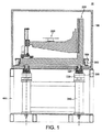
図1は、本発明の第1の実施形態によるX線装置の横断面図である。 FIG. 1 is a cross-sectional view of an X-ray apparatus according to a first embodiment of the present invention.
図1では、X線源およびX線検出器は見えない。ただし、図1の構成では、見ている人の目の位置にX線源を想定することができ、見ている人の視線方向の、供試品台220を間に挟んで、紙面の向こうにX線検出器を想定することができる。したがって、供試品台220上に配置された供試品は、X線源とX線検出器との間に置かれ、X線撮像を供試品に実施することができる。検出器が撮像アレイであれば、供試品の映像を得ることができ、供試品を供試品台220上で回転させ、映像を様々な角度方向で撮れば、CT撮像技法を使用して対象物の体積密度マップを再構成することができ、内部構造の調査が可能になる。
In FIG. 1, the X-ray source and X-ray detector are not visible. However, in the configuration of FIG. 1, an X-ray source can be assumed at the position of the viewer's eyes, and the direction of the viewer's line of sight is across the paper with the specimen table 220 in between. X-ray detectors can be envisaged. Therefore, the specimen placed on the
以下の開示では、Z方向が、紙面の中への光線経路に沿った軸になるように取られ、Y方向、または重力方向が、紙面内で垂直な、Z方向に直交する軸になるように取られ、X方向が、紙面を水平に横切り、Z方向およびY方向に直交する軸になるように取られる。 In the following disclosure, the Z direction is taken to be an axis along the ray path into the plane of the paper, and the Y direction or gravity direction is perpendicular to the Z direction perpendicular to the plane of the paper. The X direction is taken so as to cross the paper surface horizontally and to be an axis orthogonal to the Z direction and the Y direction.
図1の構成は、比較的重い供試品を、比較的コンパクトな構成で解析することを可能にすることができる。 The configuration of FIG. 1 can allow relatively heavy specimens to be analyzed in a relatively compact configuration.
そのような比較的コンパクトな構成を可能にする、図1の実施形態の第1の態様は、供試品台、X線検出器、およびX線源を封入する遮蔽封入筐体100を貫通する機器搭載要素320を設けて、遮蔽封入筐体100の大きさを増加させることを必要とせずに、また、封入筐体の外部へのX線放射の望ましくない漏出を起こさせることもなく、比較的頑丈な支持枠310によって供試品を支持することを可能にすることである。
The first aspect of the embodiment of FIG. 1, which allows such a relatively compact configuration, penetrates the shielded
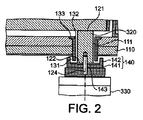
X線装置のコンパクトな大きさに寄与することができる遮蔽封入筐体100の構成が、図2に詳細に示されている。図2において、遮蔽封入筐体には、主遮蔽要素110が設けられ、その主遮蔽要素は、この場合、封入筐体の基底板の形を取る。開口111が、主遮蔽要素を内側から外側へ貫通して、搭載要素320がその開口を貫通することを可能にする。
The configuration of the shielding
搭載要素320は、ロッドとして形成され、内側端部に機器支持面121と、外側端部に基底面122とを有する。搭載要素320は、機器支持面121に載置されまたは取り付けられたあらゆる要素の重量を担持し、その重量を封入筐体の外側に配置された耐振台330へ伝達する。耐振台330を封入筐体の外側に配置することによって、封入筐体が、図1にやはり見られる耐振台支持枠310と共に耐振台330を含めて、装置全体を封入するように求められる場合よりも、封入筐体をよりコンパクトにすることが可能になる。
The mounting
一方、主遮蔽要素110などの遮蔽封入筐体の壁に開口111を設けると、通常、封入筐体の外部への望ましくないX線放射の漏出を許すことになる。したがって、本実施形態は、望ましくないX線放射の漏出を阻止する追加の遮蔽要素を採用する。
On the other hand, providing an
具体的には、周縁遮蔽要素が、開口を取り巻く主遮蔽要素の領域から延在して、搭載要素320の、主遮蔽要素110の下面を越えて突出する長さの少なくとも一部分を取り巻く。さらに、搭載要素320の基底面122には、2次遮蔽要素140が設けられ、その2次遮蔽要素は、ここでは、開口111を通り抜ける軸に垂直な面内に、周縁遮蔽要素131の外周を越えるまで延在する2次遮蔽板141として形成され、その2次遮蔽板は、そこから延出して周縁遮蔽要素131の少なくとも一部分を取り巻く2次遮蔽壁142を有する。
Specifically, the peripheral shielding element extends from the area of the main shielding element surrounding the opening and surrounds at least a portion of the length of the mounting
そのような構成を用いることにより、開口111に入射するX線は、周縁遮蔽要素131および2次遮蔽要素140の存在によって、装置の外部へ出ることが防止される。
By using such a configuration, X-rays entering the
2次遮蔽要素140が、開口111の全領域に重なりそれを覆っている場合、そのような構成は、周縁遮蔽要素および2次遮蔽要素の構造に十分な厚さのX線吸収材が使用されているならば、X線の透過を完全に阻止する。しかしながら、搭載要素320と耐振台330との確実な結合を可能にするために、搭載要素320の基底面122にねじ穴123を設けて結合ボルト124を受け入れることが有利になり得る。これを達成するために、結合ボルト124が、2次遮蔽板141に形成された開口143を貫通する。
If the secondary shielding element 140 overlaps and covers the entire area of the
そのような構成では、穴123の軸を下方へ伝播するX線は、2次遮蔽板141上に入射せずに、開口143を通過する。そのようなX線について心配がある場合には、X線が開口143を通過するのを適切に阻止するためにX線不透過性の材料を結合ボルト124として使用することができ、さもなければ、穴123の軸に小さな角度範囲で到達するX線は吸収されないことを認めた上で、そのような角度で伝播するX線を発生することを避けるようにX線源を封入筐体100内に配置する。
In such a configuration, X-rays propagating down the axis of the hole 123 do not enter the
基底面穴123と主遮蔽要素110の開口111とが軸を共有する場合には、この軸に対して5度、10度、15度、25度、または30度で伝播するX線は封入筐体から出ることができることを認めた上で、周縁遮蔽要素131および2次遮蔽要素140の寸法を適切に選択することができる。
When the basal plane hole 123 and the
図2は、封入筐体の外側に設けられた周縁遮蔽要素131および2次遮蔽要素140を示すが、同様な要素を、それら要素が封入筐体の外側に設けられている図2の構成に加えてまたはその代わりに、封入筐体の内側に設けることができる。そのような構成は、開口111および/または基底面穴123の軸に近い角度で伝播するX線に対して、さらに強い遮蔽を行うことができる。
FIG. 2 shows a peripheral shielding element 131 and a secondary shielding element 140 provided on the outside of the encapsulating housing, but similar elements are shown in the configuration of FIG. 2 in which they are provided on the outside of the enclosing housing. In addition or alternatively, it can be provided inside the enclosure. Such a configuration can provide even stronger shielding against X-rays propagating at an angle close to the axis of the
さらに、図2の構成は機器支持面121に載る機器の重量を直接担持するように、垂直に配向されている搭載要素320を示している。しかし、それに限定されることなく、開口111は、封入筐体100の床、壁、または天井を含めて、あらゆる適切な面に形成することができ、それによって機器を天井または壁から懸吊することができる。そのような構成では、機器支持面121には、懸吊される機器を取り付けるために、結合ボルトを受け入れる穴、またはフックもしくはブラケットなどの別の適切な固定手段を追加して設けることができる。
In addition, the configuration of FIG. 2 shows the mounting
図2の構成について様々な変更を考えることができる。たとえば、X線が一方向からのみ発生されることが確実であれば、遮蔽要素は、その方向から伝播するX線のみを防ぐように配置することができる。そのような構成では、X線が発射されると想定されるのとは反対側でのみ搭載要素320を部分的に取り巻くように周縁遮蔽要素131を設ければ十分であり得る。たとえば、周縁遮蔽要素は、半円筒として設けることができる。さらに、開口111の、X線が発射されると想定される方向とは反対側のみに2次遮蔽要素140を設ければ十分であり得る。当然、周縁遮蔽要素131および2次遮蔽要素140が、封入筐体100の内側に設けられる場合には、それら要素は、開口111の、X線が入射することになる側とは反対側ではなくて、X線が入射することになる側に設ける必要がある。
Various changes can be considered for the configuration of FIG. For example, if it is certain that X-rays are generated only from one direction, the shielding element can be arranged to prevent only X-rays propagating from that direction. In such a configuration, it may be sufficient to provide the peripheral shielding element 131 to partially surround the mounting
さらに、周縁遮蔽要素131は全体的に円筒形で示され、2次遮蔽要素は板部分141と円筒壁142とを有するように示されてきたが、これら構成の変形形態が可能である。たとえば、周縁遮蔽要素131および2次遮蔽壁142が、開口111から内方または外方へ突出する中空円錐の一部分として延在してもよく、2次遮蔽要素140が、たとえば、半球カップとして形成されてもよい。図2に示された構成は、空間の効率的な使用を行う視点から、今のところ、好まれている。
Furthermore, while the peripheral shielding element 131 has been shown generally cylindrical and the secondary shielding element has been shown to have a
図2の構成では、主遮蔽要素110の、周縁遮蔽要素131および2次遮蔽要素140とは反対側に、内方へ突出する内部遮蔽要素132が示されており、その内部遮蔽要素は、全体的に円筒形を有し、遮蔽要素132の内側端部から外向きに突出する内部フランジ133を有する。そのような構成を設けることが必須ではないが、そのような追加の遮蔽要素を設けると、全体の遮蔽を向上することができ、周縁遮蔽要素131および2次遮蔽140を薄くすることを可能にすることができる。
In the configuration of FIG. 2, an
図2は、搭載要素320が開口111を貫通するところを示すが、主遮蔽要素110、開口111、周縁遮蔽要素131、および2次遮蔽要素140の同様な構成を、電力および冷却水、ならびに制御電子信号および光ファイバを通る信号などの供給を行うための開口を含めて、封入筐体の壁を通り抜けるあらゆる開口を保護するために使用することができる。ただし、図1の構成において、そのような構成の主要利点は、その構成が、耐振台330および耐振台支持枠310のような嵩張る支持要素を遮蔽封入筐体100の外部に配置することを可能にし、それによって、遮蔽封入筐体の大きさおよび重量を比較的よりコンパクトな形に抑えることである。
Although FIG. 2 shows the mounting
そのような比較的コンパクトな構成を可能にする図1の実施形態の第2の態様として、図1に示された構成は、また、供試品を封入筐体から容易に降ろすことを可能にする要素を備える。 As a second aspect of the embodiment of FIG. 1 that allows such a relatively compact configuration, the configuration shown in FIG. 1 also allows the specimen to be easily removed from the enclosure. It has an element to do.
従来のX線装置では、作業者が供試品を挿入し取り外すことを可能にする窓または他の閉鎖可能な開口を封入筐体に設けることが通例である。しかし、供試品が大きく重くなるにつれて、作業者が補助なしに供試品を挿入し取り外すことが相対的により難しくなる。場合によっては、クレーンやトロリなどの特別な操作機材を、供試品を移動するために使用しなければならず、その場合、作業者にとって、供試品を封入筐体内に移し替えることが一般的に難しくなる。大きくまたは重い供試品でも容易に封入筐体に導き入れそこから取り外すのに十分大きな窓を設けることは、遮蔽封入筐体100の全体寸法を増加させる傾向になる。したがって、図1の実施形態は、供試品台220を封入筐体から引き出し、または少なくとも搭載位置もしくは搭載開口のより近くに移動させることを可能にして、供試品をより簡便に導き入れ取り降ろすことを可能にする特徴を有する。
In conventional X-ray devices, it is customary to provide the enclosure with a window or other closable opening that allows the operator to insert and remove the specimen. However, as the specimen becomes larger and heavier, it becomes relatively more difficult for an operator to insert and remove the specimen without assistance. In some cases, special operating equipment such as cranes and trolleys must be used to move the specimen, in which case it is common for the operator to transfer the specimen to the enclosure. It becomes difficult. Providing a large enough window to easily introduce and remove large or heavy specimens from the enclosure will tend to increase the overall dimensions of the
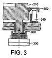
そのようなより容易な搭載を可能にするシステムの特定の要素が、図3に示されている。図1を参照して、供試品台220は、後に説明するように、供試品を封入筐体内部で容易に回転させ移動させることを可能にする、操作機構台200の一部分を形成する。操作機構台200は、該操作機構台の残りの構成要素を支持し、供試品がそれに対して回転され移動される基準面を形成する基準板210を基底として有する。
Certain elements of the system that allow such easier mounting are shown in FIG. Referring to FIG. 1, the
図3に示され、上記で説明されたように、基準板210は、作動中、耐振台330によって支持されている搭載要素320上に載っている。ここでは、耐振台330は、供試品と共に操作機構台200の重量を、たとえば耐振台330のピストン内に閉じ込められた安定した気柱上に支持する能動的耐振台である。それによって、操作機構台200が、供試品がX線ビーム経路内に位置するように、照射位置に適切に配置される。
As shown in FIG. 3 and described above, the
しかしながら、本構成では、基準板210には、レール350がさらに設けられ、そのレールは、紙面から出ていく直線内に延在する一組のローラ340の上に張り出し、それらローラの1つが図3の断面内に示されている。それに対応するレールが、基準板210の対向する側面に設けられている。この構成によって、耐振台330が無力化されるとき、搭載要素320が相対的に低くなるように空気をピストンから抜き取ることができる。搭載要素320が十分な距離まで下降すると、レール350がローラ340に載って直線支承機構を形成し、操作機構台200を、ローラ上で紙面から外へ読者の方へ向かって移動させることが可能になる。これによって、操作機構台を、たとえば、封入筐体の天井のクレーンアクセスハッチの下、さもなければ封入筐体壁の窓、扉、または開口を経て封入筐体の完全に外など、搭載位置へ移動させることが可能になり、それによって供試品を容易に搭載または取り降ろすことが可能になる。
However, in this configuration, the
供試品に適切な操作が行われた後は、次いで逆の操作が可能であり、すなわち、操作機構台200を、レール350およびローラ340によって形成された直線支承機構に沿って搭載位置から照射位置へ移動させ、次いで、耐振台330を作動させて操作機構台200を持ち上げるように働かせ、それによって、レール350がローラ340から離隔されるようになり、操作機構台200が、完全に耐振台330上の搭載要素320を介して支持される。
After an appropriate operation is performed on the specimen, the reverse operation is then possible, that is, the
安全性を増すために、図3には示されていないが、照射位置に支持されているときの基準板210の不慮の移動を防止するために、搭載要素320を受け入れる陥凹を基準板210の基底に形成してもよい。
To increase safety, although not shown in FIG. 3, in order to prevent inadvertent movement of the
当然、耐振台ではなくて、むしろ単純に、搭載要素320を基準板210の基底と接触するように持ち上げてレール350をローラ340から離れるように持ち上げる液圧または機械的昇降機を有することを含めて、図3に関する様々な変更を考案することができる。さらに、耐振台は、搭載要素320と基準板210との間、搭載要素320と昇降機機構との間、または昇降機機構と昇降機機構用の支持枠との間に配置された弾性支持体など、パッシブダンパとして実現することができる。
Of course, rather than being a vibration table, rather simply including having a hydraulic or mechanical elevator that lifts the mounting
さらに、ローラが操作機構台に設けられ、レールが封入筐体の基底に設けられる配置、または、摺動支承機構やさらには非接触型空気もしくは磁気支承機構など、他の直線支承機構に置き換えられる構成を含めて、ローラ340およびレール350の上記に開示された構成の変更形態を考案することができる。さらに、そのような構成は、限定されることなしに、耐振台さらには耐振台枠までも封入筐体内に封入される従来の封入筐体であっても使用することができる。
Furthermore, the roller is provided on the operating mechanism base and the rail is provided on the base of the enclosing housing, or replaced by other linear support mechanisms such as a sliding support mechanism or even a non-contact type air or magnetic support mechanism. Variations to the above disclosed configurations of the
最終的に、そのような構成は、放射器または検出器など、X線装置の他の重くまたは嵩張る要素を支持するために使用することができ、それによって、それら要素を、保守整備または調整のために封入筐体のアクセス領域へ、さらには封入筐体の外側にまで容易に移動させることができる。 Ultimately, such a configuration can be used to support other heavy or bulky elements of the x-ray device, such as a radiator or detector, thereby allowing the elements to be serviced or adjusted. Therefore, it can be easily moved to the access region of the encapsulating casing and further to the outside of the enclosing casing.
そのような比較的コンパクトな構成を可能にする図1の実施形態の第2の態様として、実施形態は、重くまたは嵩張る供試品を支持するように適合された操作機構台を有する。 As a second aspect of the embodiment of FIG. 1 that allows such a relatively compact configuration, the embodiment has an operating mechanism base adapted to support a heavy or bulky specimen.
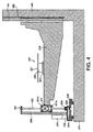
具体的には、図4に示されるように、操作機構台200は、供試品台220をその全長に亘る位置で支持する第1の支持部材230を有する。供試品台220は、供試品を支持するために十分に大きく平坦な面を形成する台座221を備える。台座221は、回転駆動機構222およびX移動搬送機構223によって支持されている。回転駆動機構222は、Y方向に向いた軸周りに台座221を制御下で回転させることを可能にし、X移動搬送機構223は、台座221と共に回転駆動機構222を第1の支持部材230に沿ってX方向に移動させることを可能にする。したがって、供試品台220は、第1の支持部材230のほぼ中央位置に支持されている。
Specifically, as shown in FIG. 4, the
供試品台220のX移動搬送機構223を用いることによって、光線横断方向での供試品の位置を調節することができ、他方、回転駆動機構222を用いて供試品を回転させることによって、供試品を通過する様々な角度でのX線映像を得ることができることにより、CTプロセスを介して体積密度マップを生成することが可能になる。
By using the X moving
本実施形態では、第1の支持部材230は、一方の端部で垂直な第2の支持部材240により、他方の端部で垂直な第3の支持部材250によって支持される梁の形態を取る。ここでは、梁は、一方の端部が他方の端部より厚い補強部分によって補強されているところが示されているが、アーチ形を有する梁構成または一様断面を有する梁構成も使用可能である。
In the present embodiment, the
第2の支持部材240には、従動体242がその中を摺動する溝241が設けられ、それにより、従動体242が溝241内で摺動することによって、第1の支持部材をY方向に昇降させることができる。この構成は、第1の支持部材の一方の端部を、自由なY方向移動を可能にしながら受動的に支持する。同様に、第2の支持部材240の外側に沿って摺動する搬送機構を有し、その搬送機構が、第2の支持部材の外側支承面と協働する内側支承面を有することによりそのような自由移動を行わせることができる構成を含めて、第1の支持部材を確実に支持しながら昇降させることが可能な他の構成を使用してもよい。
The
対照的に、第3の支持部材250は、第1の支持部材230の他方の端部を能動的方式で支持し、基準板210に対してY方向での第1の支持部材の高さを調節する駆動機構が設けられている。そのような能動的駆動を達成するために、第3の支持部材250は、ボールねじ252と、従動体ナット251とを備え、その従動体ナットは、第2の支持部材では支持されていない、第1の支持部材230の他方の端部に連結されている。ボールねじ252は、最上部でラジアル軸受253によって支持され、最下部でアンギュラコンタクト軸受254によって固定され、ステッピングモータ257によってギアボックス256および駆動ベルト255を介して駆動される。そのような構成では、固定されたアンギュラコンタクト軸受254が、端部のあらゆる浮動または遊動を除去し、作動中の軸推力の大部分を受け止める。その一方、ラジアル軸受253は、ボールねじ252の上端部を浮動可能にし、それによって、駆動機構の膨張および軽微なミスアラインメントを吸収し、一方ボールねじ252のあらゆる曲げモーメントを低減する。
In contrast, the
したがって、そのような構成によって、第1の支持部材230の垂直位置は、ボールねじ252を駆動して第1の支持部材の一方の端部を昇降させ、他方、第1の支持部材230の他方の端部はその移動に従うに委せることによって、好都合に調節することができる。
Therefore, according to such a configuration, the vertical position of the
拡大率の調節を可能にするために、供試品台220をZ方向に、すなわちX線ビームのラインに沿って移動させることができるようにするために、第3の支持部材250が、基準板210に装着されたZレール259上を移動するZ搬送機構258上に支持されている。図4に示されていないが、第1の支持部材230は、また、第2の支持部材側で、第1の従動体に形成された第2の溝の中を摺動する第2の従動体によって支持され、それによって、第1の支持部材が捻じれることなく全体としてZ方向に自由に移動することが可能になる。このように、協働する回転駆動機構222と、X移動搬送機構223と、Y調節ボールねじ252と、Z搬送機構258とを用いて、供試品台220を、X、Y、Z方向のそれぞれに移動させることができ、一方Y軸に平行な軸周りに回転させることもできる。
In order to be able to adjust the magnification factor, the
第1の支持部材230を両端部でX方向に関して支持することによって、嵩張るまたは重い負荷を供試品台220に載せても、第1の支持部材230に変形を生じさせず、供試品台220にX−Z面に対する傾斜を生じさせない。したがって、重いまたは嵩張る供試品でも、精度を欠くことなく撮像することができる。
By supporting the
当然、第1の支持部材230の第3の支持部材端部の位置を支持し調節するために、ボールねじおよびナットではなくて、ベルト駆動機構を使用することや、協働するボールねじ252およびナット251などの能動的駆動手段を第1の支持部材の両端部に設ける可能性を含めて、図4に示された構成に対して様々な変更が可能である。
Of course, to support and adjust the position of the third support member end of the
図4に示された構成では、ナット251が、背中合わせに装着された2つのボールねじナットとして構成され、それによって、ボールねじ252とナット251との間で発生した力が、各それぞれのナットのラジアル軸受251Aおよび251Bを介して支持部材230へ伝達される。Z搬送機構アセンブリは、第3の支持部材250と同様な方式でベルト構造またはボールねじによって駆動してもよく、またはラックおよびピニオン駆動機構を用いて直接駆動してもよい。たとえば、被駆動ピニオンを、Zレール259の間に横たわるラックに係合するようにZ搬送機構258に装着して、Z搬送機構をZ方向に駆動することを可能にすることができる。
In the configuration shown in FIG. 4, the
本実施形態では、第2の支持部材240および第3の支持部材250は、基準板210によって支持されているが、基準板210は、主として安定性および構造強度のために設けられている。別法として、特に、Z方向の調節が必要とされない場合、第2の支持部材240および第3の支持部材250のそれぞれを、たとえば図1に示された搭載要素320上に、直接支持することができる。
In the present embodiment, the
当業者には、上記の開示を、上記によって開示済みまたは上記から導出可能のいずれにせよ本発明の技術的成果の一部またはすべてを保持しながら、当技術分野での自己の通常の一般的な知識に照らして、本発明の範囲内で、自分自身の状況および要件に適合するように変更および改変することが可能であると考えられる。そのような同等形態、変更形態、または改変形態のすべてが、本明細書で定義され、特許請求の範囲に記載された本発明の範囲に包含される。 Those skilled in the art will recognize that the above disclosure is generally common in the art, while retaining some or all of the technical results of the present invention, whether disclosed above or derivable from the above. In light of this knowledge, changes and modifications within the scope of the present invention may be adapted to suit their own circumstances and requirements. All such equivalents, modifications, or variations are defined within the scope of the invention as defined herein and set forth in the claims.
100 遮蔽封入筐体
110 主遮蔽要素
111 開口
121 機器支持面
122 基底面
123 ねじ穴
124 結合ボルト
131 周縁遮蔽要素
132 内部遮蔽要素
133 内部フランジ
140 2次遮蔽要素
141 2次遮蔽板
142 2次遮蔽壁
143 開口
200 操作機構台
210 基準板
220 供試品台
221 台座
222 回転駆動機構
223 X移動搬送機構
230 第1の支持部材
240 第2の支持部材
241 溝
242 従動体
250 第3の支持部材
251 従動体ナット
251A ラジアル軸受
251B ラジアル軸受
252 ボールねじ
253 ラジアル軸受
254 アンギュラコンタクト軸受
255 駆動ベルト
256 ギアボックス
257 ステッピングモータ
258 Z搬送機構
259 Zレール
310 支持枠
320 機器搭載要素
330 耐振台
340 ローラ
350 レール
DESCRIPTION OF
Claims (12)
供試品台、X線検出器、およびX線源を封入する遮蔽封入筐体の基底板の形をとる主遮蔽要素であって、該主遮蔽要素の一方の側から該主遮蔽要素の他方の側へ該主遮蔽要素を貫通する少なくとも1つの開口を有する、主遮蔽要素と、
前記主遮蔽要素の前記開口を通って延在するように配置された搭載要素であり、前記開口の一方の側に機器支持面を有し、前記開口の他方の側に基底面を有する、搭載要素と、
前記搭載要素の少なくとも一部分を少なくとも部分的に取り巻くように、前記主遮蔽要素の、前記開口を取り巻く領域から延在する周縁遮蔽要素と、
前記搭載要素の前記基底面および前記機器支持面の1つに配置され、前記周縁遮蔽要素の少なくとも一部分の外周を少なくとも部分的に取り巻くように、前記主遮蔽要素の方へ延出する2次遮蔽要素と
を備える機器搭載台。 An equipment mounting table for an X-ray apparatus,
A main shielding element in the form of a base plate of a shielding enclosure enclosing a specimen table, an X-ray detector, and an X-ray source , from one side of the main shielding element to the other of the main shielding elements A main shielding element having at least one opening through the main shielding element to the side of
A mounting element arranged to extend through the opening of the main shielding element, having a device support surface on one side of the opening and a base surface on the other side of the opening Elements and
A peripheral shielding element extending from a region surrounding the opening of the main shielding element so as to at least partially surround at least a portion of the mounting element;
A secondary shield disposed on one of the base surface and the equipment support surface of the mounting element and extending toward the main shielding element so as to at least partially surround an outer periphery of at least a portion of the peripheral shielding element. Equipment mounting base with elements.
Applications Claiming Priority (3)
| Application Number | Priority Date | Filing Date | Title |
|---|---|---|---|
| GB1414395.2 | 2014-08-13 | ||
| GBGB1414395.2A GB201414395D0 (en) | 2014-08-13 | 2014-08-13 | X-ray apparatus |
| PCT/EP2015/068555 WO2016023949A1 (en) | 2014-08-13 | 2015-08-12 | X-ray apparatus |
Related Child Applications (1)
| Application Number | Title | Priority Date | Filing Date |
|---|---|---|---|
| JP2018098659A Division JP6603752B2 (en) | 2014-08-13 | 2018-05-23 | X-ray equipment |
Publications (2)
| Publication Number | Publication Date |
|---|---|
| JP2017527353A JP2017527353A (en) | 2017-09-21 |
| JP6556830B2 true JP6556830B2 (en) | 2019-08-07 |
Family
ID=51629743
Family Applications (2)
| Application Number | Title | Priority Date | Filing Date |
|---|---|---|---|
| JP2017507729A Active JP6556830B2 (en) | 2014-08-13 | 2015-08-12 | Equipment mounting base for X-ray apparatus and X-ray apparatus provided with the same |
| JP2018098659A Active JP6603752B2 (en) | 2014-08-13 | 2018-05-23 | X-ray equipment |
Family Applications After (1)
| Application Number | Title | Priority Date | Filing Date |
|---|---|---|---|
| JP2018098659A Active JP6603752B2 (en) | 2014-08-13 | 2018-05-23 | X-ray equipment |
Country Status (6)
| Country | Link |
|---|---|
| US (3) | US10365233B2 (en) |
| EP (3) | EP4657052A1 (en) |
| JP (2) | JP6556830B2 (en) |
| CN (1) | CN107110797B (en) |
| GB (1) | GB201414395D0 (en) |
| WO (1) | WO2016023949A1 (en) |
Families Citing this family (5)
| Publication number | Priority date | Publication date | Assignee | Title |
|---|---|---|---|---|
| CN106018440A (en) * | 2016-06-28 | 2016-10-12 | 国营芜湖机械厂 | Ray inspection tool for rudder of airplane |
| JP7087916B2 (en) * | 2017-11-21 | 2022-06-21 | 住友金属鉱山株式会社 | Sample measuring device and sample measuring method |
| US11774333B2 (en) * | 2019-04-04 | 2023-10-03 | Mcp Ip, Llc | Shaft testing device with non-contact bearing |
| US11955308B1 (en) * | 2022-09-22 | 2024-04-09 | Kla Corporation | Water cooled, air bearing based rotating anode x-ray illumination source |
| CN115435043A (en) * | 2022-09-30 | 2022-12-06 | 济南汉江光电科技有限公司 | X-ray microscope vibration isolation device |
Family Cites Families (31)
| Publication number | Priority date | Publication date | Assignee | Title |
|---|---|---|---|---|
| DE1217100B (en) * | 1962-10-25 | 1966-05-18 | Radiologie Cie Gle | Sample flow device for X-ray spectrometers operated under vacuum |
| JPS527263A (en) | 1975-06-16 | 1977-01-20 | Matsushita Electric Ind Co Ltd | Indicator |
| JPS527263U (en) * | 1975-06-30 | 1977-01-19 | ||
| US4273239A (en) * | 1979-04-23 | 1981-06-16 | Contran Conveyors & Systems, Inc. | Zero pressure accumulator and braking apparatus therefor |
| FR2622758B1 (en) | 1987-10-30 | 1990-04-27 | Thomson Cgr | RADIOGENIC ASSEMBLY WITH FULL PROTECTION AGAINST LEAKAGE RADIATION |
| JPH05119193A (en) * | 1991-08-15 | 1993-05-18 | Sofutetsukusu Kk | Industrial x-ray inspector |
| JP3313755B2 (en) | 1992-04-30 | 2002-08-12 | 東芝アイティー・コントロールシステム株式会社 | Tomography equipment |
| US5344238A (en) | 1992-12-18 | 1994-09-06 | Electroglas, Inc. | Ball bearing assembly |
| US5627874A (en) * | 1995-04-05 | 1997-05-06 | Smallbone; Allan H. | X-ray spectroscopic analysis of powder samples using a window-less cell system |
| CN1207199A (en) * | 1996-03-12 | 1999-02-03 | 株式会社荏原制作所 | X-ray or gamma-ray shielding equipment |
| JP3829241B2 (en) | 2002-06-19 | 2006-10-04 | 日本軽金属株式会社 | Storage |
| US7783004B2 (en) * | 2002-07-23 | 2010-08-24 | Rapiscan Systems, Inc. | Cargo scanning system |
| WO2005078419A1 (en) * | 2004-02-18 | 2005-08-25 | Pony Industry Co., Ltd. | Radiation photofluorographic device and radiation photofluorographic method |
| GB0415053D0 (en) | 2004-07-05 | 2004-08-04 | Dage Prec Ind Ltd | X-ray manipulator |
| US7131769B2 (en) * | 2004-12-16 | 2006-11-07 | Octostop Inc. | Stretcher with dedicated multi-functional removable floating patient support platform |
| JP2006214924A (en) * | 2005-02-04 | 2006-08-17 | Babcock Hitachi Kk | X-ray non-destructive inspection method, and image rt apparatus |
| US9308145B2 (en) | 2005-02-22 | 2016-04-12 | Roger P. Jackson | Patient positioning support structure |
| CN2876023Y (en) * | 2006-02-13 | 2007-03-07 | 福州泰康机械制造有限公司 | Device for bandling cargo |
| US7341376B2 (en) | 2006-03-23 | 2008-03-11 | General Electric Company | Method for aligning radiographic inspection system |
| US7873143B2 (en) * | 2007-12-03 | 2011-01-18 | X-Ray Optical Systems, Inc. | Sliding sample cell insertion and removal apparatus for x-ray analyzer |
| US7702077B2 (en) | 2008-05-19 | 2010-04-20 | General Electric Company | Apparatus for a compact HV insulator for x-ray and vacuum tube and method of assembling same |
| JP2010073477A (en) * | 2008-09-18 | 2010-04-02 | Akihiko No | X-ray tube housing container |
| CN102422380A (en) | 2009-02-22 | 2012-04-18 | 迈普尔平版印刷Ip有限公司 | Charged particle lithography apparatus and method of generating vacuum in a vacuum chamber |
| FR2959609B1 (en) | 2010-04-28 | 2013-01-11 | Michelin Soc Tech | ACCUMULATOR ASSEMBLY FOR AN ELECTRIC OR HYBRID VEHICLE BATTERY |
| DE102011005732B4 (en) * | 2011-03-17 | 2013-08-22 | Carl Zeiss Microscopy Gmbh | Device for X-ray spectroscopy |
| CN202171958U (en) * | 2011-07-22 | 2012-03-21 | 深圳市蓝韵实业有限公司 | Shielding box for detection of X-ray high voltage generator |
| CN202534370U (en) * | 2012-03-16 | 2012-11-14 | 中国核电工程有限公司 | Adjustable penetrating piece in radioactive environment |
| WO2014050931A1 (en) | 2012-09-26 | 2014-04-03 | 株式会社ニコン | X-ray device and structure manufacturing method |
| CN103640890B (en) * | 2013-12-16 | 2015-08-12 | 丹东奥龙射线仪器集团有限公司 | LNG gas cylinder X-ray digital imagery detects mechanical drive |
| CN203798748U (en) * | 2014-03-26 | 2014-08-27 | 北京华力兴科技发展有限责任公司 | Safety inspection system for passenger cars |
| DE102014007154B3 (en) * | 2014-05-15 | 2015-10-29 | Crosslinking AB | Telescopic shielding device |
-
2014
- 2014-08-13 GB GBGB1414395.2A patent/GB201414395D0/en not_active Ceased
-
2015
- 2015-08-12 EP EP25180338.3A patent/EP4657052A1/en active Pending
- 2015-08-12 WO PCT/EP2015/068555 patent/WO2016023949A1/en not_active Ceased
- 2015-08-12 EP EP25180335.9A patent/EP4607569A3/en active Pending
- 2015-08-12 EP EP15748260.5A patent/EP3180604B1/en active Active
- 2015-08-12 JP JP2017507729A patent/JP6556830B2/en active Active
- 2015-08-12 CN CN201580054885.6A patent/CN107110797B/en active Active
- 2015-08-12 US US15/503,318 patent/US10365233B2/en active Active
-
2018
- 2018-05-23 JP JP2018098659A patent/JP6603752B2/en active Active
- 2018-12-14 US US16/220,626 patent/US10571409B2/en active Active
- 2018-12-14 US US16/220,632 patent/US10571410B2/en active Active
Also Published As
| Publication number | Publication date |
|---|---|
| CN107110797A (en) | 2017-08-29 |
| JP6603752B2 (en) | 2019-11-06 |
| US10571410B2 (en) | 2020-02-25 |
| US20190137418A1 (en) | 2019-05-09 |
| EP3180604B1 (en) | 2025-10-01 |
| CN107110797B (en) | 2020-07-03 |
| US10571409B2 (en) | 2020-02-25 |
| EP3180604A1 (en) | 2017-06-21 |
| JP2018159712A (en) | 2018-10-11 |
| US10365233B2 (en) | 2019-07-30 |
| WO2016023949A1 (en) | 2016-02-18 |
| EP4607569A3 (en) | 2026-02-25 |
| EP4657052A1 (en) | 2025-12-03 |
| US20190137417A1 (en) | 2019-05-09 |
| GB201414395D0 (en) | 2014-09-24 |
| US20170234810A1 (en) | 2017-08-17 |
| EP4607569A2 (en) | 2025-08-27 |
| JP2017527353A (en) | 2017-09-21 |
Similar Documents
| Publication | Publication Date | Title |
|---|---|---|
| JP6603752B2 (en) | X-ray equipment | |
| JP2018159712A5 (en) | ||
| US10145806B2 (en) | X-ray apparatus | |
| KR102621477B1 (en) | Inline x-ray measurement apparatus and method | |
| GB2533735A (en) | Device for checking reactor pressure vessel of nuclear power station | |
| KR102534747B1 (en) | Non destructive inspection system | |
| JP4886684B2 (en) | X-ray operating device | |
| CN213046872U (en) | Sickbed mechanism of magnetic resonance system | |
| CN213665249U (en) | Overturning sickbed bottom plate of magnetic resonance system and magnetic resonance system | |
| KR102795328B1 (en) | Detector transfer device with sag prevention structure | |
| CN221903724U (en) | X-ray and PET imaging fusion device | |
| CN213046874U (en) | Omnidirectional mobile chassis of magnetic resonance system and mobile magnetic resonance system | |
| CN212965373U (en) | Differential moving chassis of magnetic resonance system and movable magnetic resonance system | |
| JP5038927B2 (en) | Container inspection device | |
| JPH07318653A (en) | Positron ct system | |
| CN107046795B (en) | Board | |
| CN114354656A (en) | System-level sample testing system and method | |
| KR20220076075A (en) | Gamma ray measuring device and nondestructive inspection system | |
| SE512202C2 (en) | Digital bucky where ion chambers and breaks can be removed from the detector | |
| JP2015184226A (en) | Radiation shielding body |
Legal Events
| Date | Code | Title | Description |
|---|---|---|---|
| A621 | Written request for application examination |
Free format text: JAPANESE INTERMEDIATE CODE: A621 Effective date: 20170330 |
|
| A977 | Report on retrieval |
Free format text: JAPANESE INTERMEDIATE CODE: A971007 Effective date: 20171220 |
|
| A131 | Notification of reasons for refusal |
Free format text: JAPANESE INTERMEDIATE CODE: A131 Effective date: 20180205 |
|
| A601 | Written request for extension of time |
Free format text: JAPANESE INTERMEDIATE CODE: A601 Effective date: 20180427 |
|
| A521 | Request for written amendment filed |
Free format text: JAPANESE INTERMEDIATE CODE: A523 Effective date: 20180523 |
|
| A131 | Notification of reasons for refusal |
Free format text: JAPANESE INTERMEDIATE CODE: A131 Effective date: 20181022 |
|
| A521 | Request for written amendment filed |
Free format text: JAPANESE INTERMEDIATE CODE: A523 Effective date: 20190118 |
|
| TRDD | Decision of grant or rejection written | ||
| A01 | Written decision to grant a patent or to grant a registration (utility model) |
Free format text: JAPANESE INTERMEDIATE CODE: A01 Effective date: 20190610 |
|
| A61 | First payment of annual fees (during grant procedure) |
Free format text: JAPANESE INTERMEDIATE CODE: A61 Effective date: 20190710 |
|
| R150 | Certificate of patent or registration of utility model |
Ref document number: 6556830 Country of ref document: JP Free format text: JAPANESE INTERMEDIATE CODE: R150 |
|
| R250 | Receipt of annual fees |
Free format text: JAPANESE INTERMEDIATE CODE: R250 |
|
| R250 | Receipt of annual fees |
Free format text: JAPANESE INTERMEDIATE CODE: R250 |
|
| R250 | Receipt of annual fees |
Free format text: JAPANESE INTERMEDIATE CODE: R250 |
|
| R250 | Receipt of annual fees |
Free format text: JAPANESE INTERMEDIATE CODE: R250 |