JP6552913B2 - Control device for power generation system, power generation system, and power generation method - Google Patents
Control device for power generation system, power generation system, and power generation method Download PDFInfo
- Publication number
- JP6552913B2 JP6552913B2 JP2015160126A JP2015160126A JP6552913B2 JP 6552913 B2 JP6552913 B2 JP 6552913B2 JP 2015160126 A JP2015160126 A JP 2015160126A JP 2015160126 A JP2015160126 A JP 2015160126A JP 6552913 B2 JP6552913 B2 JP 6552913B2
- Authority
- JP
- Japan
- Prior art keywords
- value
- steam
- load capacity
- turbine
- steam turbine
- Prior art date
- Legal status (The legal status is an assumption and is not a legal conclusion. Google has not performed a legal analysis and makes no representation as to the accuracy of the status listed.)
- Active
Links
Images


Classifications
-
- F—MECHANICAL ENGINEERING; LIGHTING; HEATING; WEAPONS; BLASTING
- F01—MACHINES OR ENGINES IN GENERAL; ENGINE PLANTS IN GENERAL; STEAM ENGINES
- F01D—NON-POSITIVE DISPLACEMENT MACHINES OR ENGINES, e.g. STEAM TURBINES
- F01D17/00—Regulating or controlling by varying flow
- F01D17/20—Devices dealing with sensing elements or final actuators or transmitting means between them, e.g. power-assisted
- F01D17/22—Devices dealing with sensing elements or final actuators or transmitting means between them, e.g. power-assisted the operation or power assistance being predominantly non-mechanical
- F01D17/24—Devices dealing with sensing elements or final actuators or transmitting means between them, e.g. power-assisted the operation or power assistance being predominantly non-mechanical electrical
-
- F—MECHANICAL ENGINEERING; LIGHTING; HEATING; WEAPONS; BLASTING
- F01—MACHINES OR ENGINES IN GENERAL; ENGINE PLANTS IN GENERAL; STEAM ENGINES
- F01D—NON-POSITIVE DISPLACEMENT MACHINES OR ENGINES, e.g. STEAM TURBINES
- F01D17/00—Regulating or controlling by varying flow
- F01D17/02—Arrangement of sensing elements
- F01D17/04—Arrangement of sensing elements responsive to load
-
- F—MECHANICAL ENGINEERING; LIGHTING; HEATING; WEAPONS; BLASTING
- F01—MACHINES OR ENGINES IN GENERAL; ENGINE PLANTS IN GENERAL; STEAM ENGINES
- F01D—NON-POSITIVE DISPLACEMENT MACHINES OR ENGINES, e.g. STEAM TURBINES
- F01D17/00—Regulating or controlling by varying flow
- F01D17/20—Devices dealing with sensing elements or final actuators or transmitting means between them, e.g. power-assisted
-
- F—MECHANICAL ENGINEERING; LIGHTING; HEATING; WEAPONS; BLASTING
- F01—MACHINES OR ENGINES IN GENERAL; ENGINE PLANTS IN GENERAL; STEAM ENGINES
- F01K—STEAM ENGINE PLANTS; STEAM ACCUMULATORS; ENGINE PLANTS NOT OTHERWISE PROVIDED FOR; ENGINES USING SPECIAL WORKING FLUIDS OR CYCLES
- F01K23/00—Plants characterised by more than one engine delivering power external to the plant, the engines being driven by different fluids
- F01K23/02—Plants characterised by more than one engine delivering power external to the plant, the engines being driven by different fluids the engine cycles being thermally coupled
- F01K23/06—Plants characterised by more than one engine delivering power external to the plant, the engines being driven by different fluids the engine cycles being thermally coupled combustion heat from one cycle heating the fluid in another cycle
- F01K23/10—Plants characterised by more than one engine delivering power external to the plant, the engines being driven by different fluids the engine cycles being thermally coupled combustion heat from one cycle heating the fluid in another cycle with exhaust fluid of one cycle heating the fluid in another cycle
-
- F—MECHANICAL ENGINEERING; LIGHTING; HEATING; WEAPONS; BLASTING
- F05—INDEXING SCHEMES RELATING TO ENGINES OR PUMPS IN VARIOUS SUBCLASSES OF CLASSES F01-F04
- F05D—INDEXING SCHEME FOR ASPECTS RELATING TO NON-POSITIVE-DISPLACEMENT MACHINES OR ENGINES, GAS-TURBINES OR JET-PROPULSION PLANTS
- F05D2270/00—Control
Description
本発明は、発電システムの制御装置、発電システム、及び発電方法に関するものである。 The present invention relates to a control device of a power generation system, a power generation system, and a power generation method.
舶用の排熱回収(以下「舶用排熱回収」という。)として、船舶推進用のディーゼルエンジン(メインエンジン)の排ガスの一部を抽気してパワータービンに導き発電出力として利用すると共に、ディーゼルエンジンの排ガスを用いて生成された蒸気を蒸気タービンに導き発電出力として利用する発電システムが知られている。このような発電システムには、蒸気タービンにガバナが設置され、蒸気タービンを駆動するための流体の流量を調整している。 For marine exhaust heat recovery (hereinafter referred to as “marine exhaust heat recovery”), a portion of exhaust gas from a marine propulsion diesel engine (main engine) is extracted and led to a power turbine for use as a power generation output. There is known a power generation system which uses steam generated by using the exhaust gas of the present invention and guides the steam to a steam turbine as a power generation output. In such a power generation system, a governor is installed in the steam turbine, and the flow rate of the fluid for driving the steam turbine is adjusted.
特許文献1には、蒸気タービンにガバナが設置され、ガバナが生成する制御信号が調整弁に出力されることで蒸気タービンの出力が変化することが開示されている。
上記のような舶用排熱回収において、生成した蒸気を最大限に蒸気タービンに流入させて発電機出力として回収するための一例として、蒸気タービンに導入する蒸気量を制御する調速弁を可能な限り全開位置として運転する変圧運転がある。変圧運転による排熱回収では、メインエンジンからの排熱量によって蒸気圧力が変化するため、蒸気タービンで発生可能な最大出力も変化する。 In the above-described marine exhaust heat recovery, as an example for allowing the generated steam to flow into the steam turbine to the maximum and recovering it as a generator output, it is possible to use a control valve to control the amount of steam introduced to the steam turbine As long as it is in the fully open position, there is a transformation operation. In exhaust heat recovery by transformer operation, the steam pressure changes depending on the amount of exhaust heat from the main engine, and therefore the maximum output that can be generated by the steam turbine also changes.
ここで、発電システムを構成する他の発電機(ディーゼルエンジン発電機)との負荷分担について、陸上プラントにおける発電との相違点と共に説明する。 Here, load sharing with other generators (diesel engine generators) constituting the power generation system will be described together with differences from the power generation in the land plant.
商用電源系統と系統連系され、無限大母線と並列に接続可能な陸上プラントにおける発電では、発電電力の周波数は無限大母線の系統周波数により決定される。このため、商用電源系統と系統連系される陸上プラントでは、調速弁開度を全開又は全開近傍で固定し、成り行きで発電電力を出力することができる。
一方、舶用の発電システムは、無限大母線と接続されていない、所謂マイクログリッド(アイランドモードともいう。)であるため、発電機のガバナは調速弁開度を固定できず、調速制御で動作する。また、PMS(Power Management System;パワーマネジメントシステム)が発電電力の周波数を監視し、周波数が所定値となるように、各発電機の負荷容量(Available power;発電機で利用可能な出力)を用いて負荷分担を制御する。そして、変圧運転による舶用排熱回収では、発電機の負荷容量を一定値に固定できないので、発電電力の制御に以下のような手法を用いている。
In the case of power generation in a land plant that is interconnected with a commercial power supply system and can be connected in parallel with an infinite bus, the frequency of generated power is determined by the system frequency of the infinite bus. For this reason, in a land plant connected to a commercial power supply system, the control valve opening degree can be fixed at full opening or near full opening, and it is possible to output the generated power as a matter of course.
On the other hand, since the marine power generation system is a so-called micro grid (also referred to as island mode) which is not connected to an infinite bus, the governor of the generator can not fix the degree of control valve opening. Operate. Moreover, PMS (Power Management System; Power Management System) monitors the frequency of the generated power, and uses the load capacity (Available power: available output of the generator) of each generator so that the frequency becomes a predetermined value. Control load sharing. And in ship waste heat recovery by transformer operation, since the load capacity of a generator cannot be fixed to a fixed value, the following method is used for control of generated power.
ここで、舶用排熱回収の変圧運転では、排熱量の変化に加えて主蒸気圧力も変化するが、変化に応じて発電機の負荷容量を計測と演算とによって正確に算出することは困難である。
このため、従来では、図9に示されるように、PMS100が負荷容量値保持部102で負荷容量値を予め保持(記憶)し、TCP(Turbine Control Panel;タービンコントロールパネル)104から出力されるパルス信号(オン・オフ信号)によって、負荷容量値保持部102で保持している負荷容量値を増減させる。TCP104から出力されるパルス信号は、主蒸気圧力と調速弁開度に基づくものであり、所定値ずつ段階的に負荷容量値を増加(インクリメント)又は減少(デクリメント)させる値である。このように、保持している負荷容量値をパルス信号によって段階的に増減させる制御を行う理由は、変圧運転において負荷容量値の絶対値を正確に算出することが困難なためである。
Here, in the transformer operation of marine exhaust heat recovery, the main steam pressure changes in addition to the change in the amount of exhaust heat, but it is difficult to accurately calculate the load capacity of the generator by measurement and calculation according to the change. is there.
For this reason, conventionally, as shown in FIG. 9, the
さらに、図9を参照して、変圧運転における従来のガバナ制御について詳細に説明する。
PMS100は、負荷分担制御部106及びガバナ増減パルス生成部108を備える。負荷分担制御部106は、負荷容量値保持部102で保持している負荷容量値に基づいて、蒸気タービン及び他の発電機110(ディーゼルエンジン発電機)の負荷分担を示す負荷分担信号を生成する。ガバナ増減パルス生成部108は、負荷分担制御部106からの負荷分担信号に基づいて、蒸気タービン及び他の発電機110に対して、制御値(速度設定)を増加又は減少させるためのガバナ増減パルス信号を生成し、ガバナ112A,112B,112Cへ出力する。
なお、ガバナ112Aは、TCP104に備えられ、蒸気タービンの回転速度を制御するものであり、PMS100が指示する回転速度の速度設定(ガバナ増減パルス信号)に応じた調速弁開度を調速弁へ出力することで、蒸気タービンの出力を制御すると共に、調速弁開度が目標開度となるように制御される。
また、ガバナ112B,112Cは、各々発電機110に備えられ、発電機110の回転速度を制御するものであり、PMS100が指示する回転速度の速度設定(ガバナ増減パルス信号)に応じた調速弁開度を調速弁へ出力することで、発電機110の出力を制御する。
Furthermore, with reference to FIG. 9, the conventional governor control in the transformation operation will be described in detail.
The
The governor 112A is provided in the TCP 104 to control the rotational speed of the steam turbine, and controls the degree of control valve opening according to the speed setting (the governor increase / decrease pulse signal) of the rotational speed instructed by the
Further, the
一方、TCP104は、上記パルス信号をPMS100へ出力するために、一例として、比較部114、比較部116、増パルス出力部118、及び減パルス出力部120を備える。比較部114は、蒸気タービンの調速弁の実際の開度と目標開度とを比較する。比較部116は、主蒸気圧力の計測値と主蒸気圧力の最低圧力の設定値とを比較する。そして、増パルス出力部118は、比較部114,116の比較結果に基づいて、負荷容量値を増加させる増パルス信号を生成する。また、減パルス出力部120は、比較部114,116の比較結果に基づいて、負荷容量値を減少させる減パルス信号を生成する。
すなわち、比較部114,116による比較の結果、調速弁開度が目標開度に満たない場合は、増パルス信号が増パルス出力部118からPMS100へ出力される。また、比較部114,116による比較の結果、調速弁開度が目標開度を超えた場合や、主蒸気圧力が最低圧力未満となった場合は、減パルス出力部120から減パルス信号がPMS100へ出力される。
On the other hand, the TCP 104 includes, for example, a
That is, as a result of the comparison by the
PMS100は、TCP104からのパルス信号が入力されると、負荷容量値保持部102に保持している負荷容量値をパルス信号に応じて増減させる。PMS100は、増減させた負荷容量値に基づいて、負荷分担制御部106によって蒸気タービン及び他の発電機110の負荷分担を決定し、ガバナ増減パルス信号をガバナ112A,112B,112Cへ出力する。そして、上述した様にガバナ112Aが調速弁開度を制御し、制御後の調速弁開度が目標開度と異なる等の場合には、さらに、増パルス信号又は減パルス信号がTCP104からPMS100へ出力され、所定値ずつ段階的に負荷容量値が増減される。
When the pulse signal from the TCP 104 is input, the
ここで、舶用排熱回収におけるプラント状態が変化することで排熱量等も変化すると、実際の負荷容量も変化するので、それに応じてPMS100で保持している負荷容量値も上述のようにして変化させる必要がある。
しかしながら、負荷容量値は、TCP104からのパルス信号によって増減するので、負荷容量値の変化の速さはパルス信号の間隔(以下「パルス間隔」という。)や幅(以下「パルス幅」という。)に依存する。さらに、PMS100では、TCP104からのパルス信号に対して重み付けを行い、負荷容量値を変化させる場合がある。このような場合には、負荷容量値の変化の速さは、重み付けにも依存することとなる。なお、重み付けは、例えば、調速弁開度、主蒸気圧力、蒸気タービン発電機の出力(以下「STG出力」という。)、及び主機エンジン負荷等に基づいて行われる。
Here, when the amount of waste heat etc. changes due to changes in the plant state in marine exhaust heat recovery, the actual load capacity also changes, and accordingly, the load capacity value held by
However, since the load capacity value is increased or decreased by the pulse signal from the TCP 104, the speed of change of the load capacity value is the pulse signal interval (hereinafter referred to as “pulse interval”) and width (hereinafter referred to as “pulse width”). Depends on. Furthermore, in the
上記のような、TCP104から出力されるパルス信号のパルス間隔やパルス幅、及びPMS100におけるパルス信号への重み付け等は、排熱量等のプラント状態が変化した場合において、STG出力の応答に影響を及ぼす要因であると共に応答を調整するための調整項目である。そして、STG出力の応答を適切に制御できない場合には、ハンチング等が生じる可能性がある。
ところが、パルス信号による負荷容量値の増減は、段階的な増減等により時間遅れが生じる。このため、プラント状態が変化しても、その度にプラント状態の最適値を遅れなく負荷容量値に反映できず、調速弁の開度制御にも遅れが生じる。従って、TCP104から出力されるパルス信号のパルス間隔やパルス幅、及びPMS100におけるパルス信号への重み付け等を調整しても、ハンチングを抑制できない場合がある。
The pulse interval and pulse width of the pulse signal output from the TCP 104 and the weighting to the pulse signal in the
However, the increase or decrease of the load capacitance value due to the pulse signal causes a time delay due to a stepwise increase or decrease. For this reason, even if the plant state changes, the optimum value of the plant state cannot be reflected in the load capacity value without delay each time, and the opening control of the governor valve is also delayed. Therefore, hunting may not be suppressed even if the pulse interval and pulse width of the pulse signal output from the TCP 104 and the weighting of the pulse signal in the
また、STGにパワータービンが接続されているプラントにおいて、上記のように、主蒸気圧力や調速弁開度を目標値に保つように負荷容量値をパルス信号によって増減させるだけでは、パワータービンの出力が変化しても負荷容量値は変化しない。 Further, in a plant where a power turbine is connected to STG, as described above, it is necessary to increase or decrease the load capacity value with a pulse signal so as to maintain the main steam pressure and the control valve opening at target values. Even if the output changes, the load capacity value does not change.
ここで、パワータービンにガバナが設置されていない構成におけるパルス信号を用いた従来の制御について説明する。
パルス信号を用いた従来の制御では、プラントの状態が変化することでパワータービンの出力が変化した場合、周波数も変化する。このため、ガバナ112Aがドループ特性によってパワータービンの出力変化を吸収するように動作し、これによって調速弁開度を変化させる。その後、PMS100が、主蒸気圧力や調速弁開度を目標値に保つように負荷容量値をパルス信号によって増減させることとなる。
このように、パルス信号を用いた従来の制御では、蒸気タービンの調速弁がパワータービンの出力変化に応じて、また負荷容量値の変化に応じてその都度制御される。このため、プラントの状態が変化している間に、調速弁開度が過度に低下したり、全開位置で固定されたりすることで、制御が不安定になる可能性があった。
Here, conventional control using pulse signals in a configuration in which the governor is not installed in the power turbine will be described.
In the conventional control using the pulse signal, when the output of the power turbine changes due to the change in the state of the plant, the frequency also changes. For this reason, the governor 112A operates to absorb the output change of the power turbine by the droop characteristic, thereby changing the degree of control valve opening. Thereafter, the
As described above, in the conventional control using the pulse signal, the control valve of the steam turbine is controlled each time according to the change of the output of the power turbine and the change of the load capacity value. Therefore, while the state of the plant is changing, the control valve may be excessively reduced or fixed at the fully open position, which may make the control unstable.
以上説明したように、従来の舶用排熱回収では、パルス信号によって負荷容量値を増減させているために、プラントの状態が変化すると制御が不安定となる可能性があった。 As described above, in the conventional marine exhaust heat recovery, since the load capacity value is increased or decreased by the pulse signal, there is a possibility that the control becomes unstable if the state of the plant changes.
本発明は、このような事情に鑑みてなされたものであって、プラントの状態が変化した場合の排熱回収において、より安定な制御を可能とする、発電システムの制御装置、発電システム、及び発電方法を提供することを目的とする。 The present invention has been made in view of such circumstances, and is a control device of a power generation system, a power generation system, and the like, which enables more stable control in exhaust heat recovery when the state of a plant changes. An object is to provide a power generation method.
上記課題を解決するために、本発明の発電システムの制御装置、発電システム、及び発電方法は以下の手段を採用する。 In order to solve the above-described problems, the power generation system control device, power generation system, and power generation method of the present invention employ the following means.
本発明の第一態様に係る発電システムの制御装置は、排ガスによって生成された蒸気によって駆動される蒸気タービンと、前記蒸気タービンに導入する蒸気量を制御する調速弁と、前記蒸気タービンに接続された発電機と、を具備し、前記蒸気タービンに導入する蒸気圧を変化させる変圧運転を行う発電システムの制御装置であって、前記調速弁の目標開度と前記調速弁の実際の開度との偏差に基づいて、前記蒸気タービンから得られる実際の負荷容量値を算出する算出手段と、前記算出手段によって算出された前記負荷容量値に基づいて、前記調速弁の開度を制御する制御手段と、を備え、前記算出手段は、前記調速弁の目標開度と前記調速弁の実際の開度との偏差に基づく第1負荷容量値、及び前記蒸気タービンに導入する蒸気圧の設定値と実際の蒸気圧との偏差に基づく第2負荷容量値のうちより小さな値を、前記蒸気タービンから得られる実際の負荷容量値として算出する。 A control device of a power generation system according to a first aspect of the present invention is connected to a steam turbine driven by steam generated by exhaust gas, a speed control valve for controlling the amount of steam introduced to the steam turbine, and the steam turbine A control device for a power generation system, the control device comprising: a generator, and performing variable pressure operation to change a steam pressure introduced to the steam turbine, wherein the target opening degree of the speed control valve is an actual value of the speed control valve. Based on the deviation from the opening, a calculating means for calculating an actual load capacity value obtained from the steam turbine, and based on the load capacity value calculated by the calculating means, the opening of the governor valve is determined. Control means for controlling, and the calculation means introduces a first load capacity value based on a deviation between a target opening of the governing valve and an actual opening of the governing valve, and the steam turbine Vapor pressure setting Smaller than in the second load capacitance values based on the deviation between the actual vapor pressure when, you calculated as the actual load capacitance value obtained from the steam turbine.
本構成に係る発電システムは、排ガスによって生成された蒸気によって駆動される蒸気タービン、蒸気タービンに導入する蒸気量を制御する調速弁、及び蒸気タービンに接続された発電機を備え、排熱を発電に用いる排熱回収を行う。排ガスは、一例として、メインエンジンによって生成される。そして、本構成に係る発電システムは、調速弁の開度が一定(目標開度)となるように制御することで、蒸気タービンに導入する蒸気圧を変化させる変圧運転を行う。 The power generation system according to the present configuration includes a steam turbine driven by steam generated by exhaust gas, a control valve controlling an amount of steam introduced into the steam turbine, and a generator connected to the steam turbine, Recover exhaust heat used for power generation. The exhaust gas is generated by the main engine as an example. And the electric power generation system which concerns on this structure performs the transformation operation which changes the steam pressure introduce | transduced into a steam turbine by controlling so that the opening degree of a governor valve becomes fixed (target opening degree).
ここで、従来の制御では、例えば、PMSに発電機で利用可能な蒸気タービンの出力を示す負荷容量値を予め保持し、TCPから出力されるパルス信号によって、保持している負荷容量値を所定値ずつ段階的に増減させる。そして、この保持している負荷容量値に基づいて、制御手段が蒸気タービンの調速弁を制御することで、蒸気タービンの出力を制御すると共に調速弁開度が目標開度となるように制御される。
しかしながら、パルス信号による負荷容量値の増減は、時間遅れが生じるため、プラント状態が変化しても、その度にプラント状態の最適値を遅れなく負荷容量値に反映できず、調速弁の開度制御にも遅れが生じる。
Here, in the conventional control, for example, the PMS holds in advance a load capacity value indicating the output of the steam turbine usable by the generator, and the held load capacity value is specified by the pulse signal output from the TCP. Increase or decrease the value step by step. Then, the control means controls the regulating valve of the steam turbine based on the held load capacity value, thereby controlling the output of the steam turbine and setting the regulating valve opening to the target opening degree. It is controlled.
However, because the load capacity value increases or decreases due to the pulse signal, a time delay occurs, so even if the plant condition changes, the optimum value of the plant condition can not be reflected on the load capacity value without delay. There is also a delay in the degree control.
そこで、本構成は、調速弁の目標開度と調速弁の実際の開度との偏差に基づいて、算出手段によって蒸気タービンから得られる実際の負荷容量値を絶対値として算出する。算出手段で算出される負荷容量値は、従来のようなパルス信号ではなく、アナログ信号(電圧値)である。そして、算出された負荷容量値に基づいて、制御手段によって調速弁の開度が制御され、調速弁開度が目標開度に近づけられる。 Therefore, in the present configuration, the actual load capacity value obtained from the steam turbine is calculated as an absolute value by the calculation means based on the deviation between the target opening of the governing valve and the actual opening of the governing valve. The load capacity value calculated by the calculating means is not a conventional pulse signal but an analog signal (voltage value). Then, based on the calculated load capacity value, the opening degree of the speed control valve is controlled by the control means, and the speed control valve opening degree is brought close to the target opening degree.
このように、本構成では、実際の負荷容量値を様々な計測値によって算出するものではなく、実際の調速弁開度と目標開度との偏差に基づいて負荷容量値を算出し、調速弁開度を制御する。すなわち、本構成は、実際の調速弁開度と目標開度を比較し、調速弁開度が目標開度となるように負荷容量値を増減させる。これにより、本構成は、調速弁開度の制御に用いる負荷容量値を従来のようにパルス信号で増減しないので、パルス信号特有の時間遅れを生じることなく、調速弁を制御できる。
従って、本構成は、プラントの状態が変化した場合の排熱回収において、より安定な制御を可能とする。
また調速弁の開度が開くほど蒸気圧は低下するが、蒸気圧には最小値が設定されているため、実際の蒸気圧が設定されている最小値未満とならないようにする必要がある。ここで、第2負荷容量値が第1負荷容量値よりも小さい場合とは、実際の蒸気圧が設定最小値未満となる場合である。このような場合には、第2負荷容量値が選択され、実際の蒸気圧を最小値以上に維持することができる負荷容量値が算出される。
これにより、蒸気タービンに導入する蒸気圧が設定された最小値未満となることを防止できる。
As described above, in this configuration, the actual load capacity value is not calculated based on various measured values, but the load capacity value is calculated based on the deviation between the actual speed control valve opening and the target opening. Control the speed valve opening. That is, this configuration compares the actual speed control valve opening with the target opening, and increases or decreases the load capacity value so that the speed control valve opening becomes the target opening. Thereby, since this structure does not increase / decrease the load capacity value used for control of a speed control valve opening with a pulse signal like the past, it can control a speed control valve, without producing the time delay peculiar to a pulse signal.
Therefore, this configuration enables more stable control in exhaust heat recovery when the state of the plant changes.
Also, although the vapor pressure decreases as the degree of opening of the speed control valve opens, the vapor pressure is set to a minimum value, so it is necessary to ensure that the actual vapor pressure does not fall below the set minimum value. . Here, the case where the second load capacity value is smaller than the first load capacity value is a case where the actual vapor pressure is less than the set minimum value. In such a case, the second load capacity value is selected, and the load capacity value that can maintain the actual vapor pressure at or above the minimum value is calculated.
Thereby, it can prevent that the steam pressure introduce | transduced into a steam turbine becomes less than the set minimum value.
上記第一態様では、前記算出手段で算出される前記負荷容量値に、上限が定められてもよい。 In the first aspect, an upper limit may be set for the load capacity value calculated by the calculating means.
本構成によれば、負荷容量値の上限は、例えば、メインエンジンの負荷及び外気温度に基づいて算出される値であり、負荷容量値に上限が定められるので、現実に則した負荷容量値が算出される。 According to this configuration, the upper limit of the load capacity value is, for example, a value calculated based on the load of the main engine and the outside air temperature, and the upper limit is determined for the load capacity value. Calculated.
上記第一態様では、前記排ガスによって駆動されるパワータービンを具備し、前記発電機が、前記パワータービン及び前記蒸気タービンに接続され、前記算出手段が、算出した前記負荷容量値と前記パワータービンの出力値との和を前記発電機で利用可能な負荷容量値として出力してもよい。 In the first aspect described above, a power turbine driven by the exhaust gas is provided, the generator is connected to the power turbine and the steam turbine, and the calculation means calculates the calculated load capacity value and the power turbine. You may output the sum with an output value as a load capacity value which can be utilized with the said generator.
本構成によれば、発電機がパワータービン及び蒸気タービンに接続されていても、簡易に発電機で利用可能な負荷容量値を算出できる。 According to this configuration, even if the generator is connected to the power turbine and the steam turbine, it is possible to easily calculate the load capacity value that can be used by the generator.
上記第一態様では、前記パワータービンの出力値が、前記発電機の出力の計測値から前記蒸気タービンの出力の計算値を減算して算出されてもよい。 In the first aspect, the output value of the power turbine may be calculated by subtracting the calculated value of the output of the steam turbine from the measured value of the output of the generator.
本構成によれば、簡易にパワータービンの出力値の絶対値を算出できる。 According to this configuration, the absolute value of the output value of the power turbine can be easily calculated.
本発明の第二態様に係る発電システムの制御装置は、排ガスによって駆動されるパワータービンと、前記排ガスによって生成された蒸気によって駆動される蒸気タービンと、前記蒸気タービンに導入する蒸気量を制御する調速弁と、前記パワータービン及び前記蒸気タービンに接続された発電機と、を具備し、前記蒸気タービンに導入する蒸気圧を変化させる変圧運転を行う発電システムの制御装置であって、前記調速弁の目標開度と前記調速弁の実際の開度との偏差に基づいて、前記蒸気タービンから得られる実際の負荷容量値を算出する第1算出手段と、前記第1算出手段によって算出された前記負荷容量値に基づいて、前記調速弁の開度を制御する第1制御手段と、前記パワータービンの出力値を前記発電機の出力の計測値から前記蒸気タービンの出力の計算値を減算することで算出し、算出した前記パワータービンの出力値を前記蒸気タービンから得られる負荷容量値に加算することで前記発電機の負荷容量値を算出する第2算出手段と、前記第2算出手段によって算出された前記発電機の負荷容量値に基づいて、前記調速弁の開度を制御する制御手段と、を備え、前記第1算出手段は、前記調速弁の目標開度と前記調速弁の実際の開度との偏差に基づく第1負荷容量値、及び前記蒸気タービンに導入する蒸気圧の設定値と実際の蒸気圧との偏差に基づく第2負荷容量値のうちより小さな値を、前記蒸気タービンから得られる実際の負荷容量値として算出する。 A control device of a power generation system according to a second aspect of the present invention controls a power turbine driven by an exhaust gas, a steam turbine driven by steam generated by the exhaust gas, and a steam amount introduced to the steam turbine A control device for a power generation system, comprising: a control valve, a generator connected to the power turbine and the steam turbine, and performing a transformation operation to change a steam pressure introduced to the steam turbine, the control First calculation means for calculating an actual load capacity value obtained from the steam turbine based on a deviation of a target opening degree of a speed valve and an actual opening degree of the speed regulating valve, and calculation by the first calculation means on the basis of the said load capacitance value, said first control means for controlling an opening degree of the governor valve, the output value of the power turbine from the measured value of the output of the generator steam Calculated by subtracting the calculated value of the output of the turbine, the second calculation that calculates the load capacitance value of the generator the calculated output value of the power turbine by adding the load capacitance value obtained from the steam turbine Means, and control means for controlling the opening degree of the speed regulating valve based on the load capacity value of the generator calculated by the second calculation means , the first calculation means comprising the speed control A first load capacity value based on the deviation between the target opening of the valve and the actual opening of the governing valve, and a second based on the deviation between the set value of the steam pressure introduced into the steam turbine and the actual steam pressure. smaller than of the load capacitance, calculated as the actual load capacitance value obtained from the steam turbine.
本構成に係る発電システムは、排ガスによって駆動されるパワータービン、排ガスによって生成された蒸気によって駆動される蒸気タービン、蒸気タービンに導入する蒸気量を制御する調速弁、パワータービン及び蒸気タービンに接続された発電機を備え、排熱を発電に用いる排熱回収を行う。排ガスは、一例として、メインエンジンによって生成される。そして、本構成に係る発電システムは、調速弁の開度が一定(目標開度)となるように制御することで、蒸気タービンに導入する蒸気圧を変化させる変圧運転を行う。 The power generation system according to this configuration is connected to a power turbine driven by exhaust gas, a steam turbine driven by steam generated by the exhaust gas, a governing valve that controls the amount of steam introduced into the steam turbine, a power turbine, and a steam turbine The exhaust heat recovery which uses the generated heat and uses exhaust heat for power generation is performed. The exhaust gas is generated by the main engine as an example. And the electric power generation system which concerns on this structure performs the transformation operation which changes the steam pressure introduce | transduced into a steam turbine by controlling so that the opening degree of a governor valve becomes fixed (target opening degree).
パルス信号を用いた従来の制御では、蒸気タービンの調速弁がパワータービンの出力変化に応じて、また負荷容量値の変化に応じてその都度制御されるので、プラントの状態が変化している間に、調速弁開度が過度に低下したり、全開位置で固定されたりすることで、制御が不安定になる可能性があった。 In the conventional control using a pulse signal, the control valve of the steam turbine is controlled each time according to the change of the output of the power turbine and also according to the change of the load capacity value, so the state of the plant changes. In the meantime, there is a possibility that the control becomes unstable because the opening of the governing valve is excessively lowered or fixed at the fully open position.
一方、本構成では、パワータービンの出力値を発電機の出力の計測値から蒸気タービンの出力の計算値を減算することで算出し、算出したパワータービンの出力値を蒸気タービンから得られる負荷容量値に加算することで発電機の負荷容量値を算出する。このため、パワータービンの出力変化が発電機の負荷容量値にリアルタイムで反映される。これにより、パワータービンの出力が変化しても、算出した発電機の負荷容量値を時間遅れ無く算出でき、これによって、調速弁の制御を安定化できる。
従って、本構成は、プラントの状態が変化した場合の排熱回収において、より安定な制御を可能とする。
On the other hand, in this configuration, the output value of the power turbine is calculated by subtracting the calculated value of the output of the steam turbine from the measured value of the output of the generator, and the calculated output value of the power turbine is the load capacity obtained from the steam turbine The load capacity value of the generator is calculated by adding to the value. For this reason, the output change of the power turbine is reflected in real time on the load capacity value of the generator. Thereby, even if the output of the power turbine changes, the calculated load capacity value of the generator can be calculated without a time delay, thereby stabilizing the control of the speed regulating valve.
Therefore, this configuration enables more stable control in exhaust heat recovery when the state of the plant changes.
本発明の第三態様に係る発電システムは、上記記載の制御装置を備え、前記蒸気タービンに導入する蒸気圧を変化させる変圧運転を行う。 A power generation system according to a third aspect of the present invention includes the above-described control device, and performs a transformation operation that changes a steam pressure introduced into the steam turbine.
本発明の第四態様に係る発電方法は、排ガスによって生成された蒸気によって蒸気タービンを駆動する工程と、前記蒸気タービンに導入する蒸気量を調速弁によって制御する工程と、前記蒸気タービンの駆動により発電を行う工程と、を具備し、前記蒸気タービンに導入する蒸気圧を変化させる変圧運転を行う発電方法であって、前記調速弁の目標開度と前記調速弁の実際の開度との偏差に基づいて、前記蒸気タービンから得られる実際の負荷容量値を算出する第1工程と、前記第1工程によって算出した前記負荷容量値に基づいて、前記調速弁の開度を制御する第2工程と、前記調速弁の目標開度と前記調速弁の実際の開度との偏差に基づく第1負荷容量値、及び前記蒸気タービンに導入する蒸気圧の設定値と実際の蒸気圧との偏差に基づく第2負荷容量値のうちより小さな値を、前記蒸気タービンから得られる実際の負荷容量値として算出する第3工程と、を備える。 A power generation method according to a fourth aspect of the present invention comprises the steps of: driving a steam turbine by steam generated by exhaust gas; controlling the amount of steam introduced to the steam turbine with a speed control valve; and driving the steam turbine A power generation method comprising: a step of performing power generation, and performing a transformer operation for changing a steam pressure introduced into the steam turbine, wherein the target opening of the governing valve and the actual opening of the governing valve The first step of calculating the actual load capacity value obtained from the steam turbine based on the deviation from the above, and the opening degree of the governing valve is controlled based on the load capacity value calculated in the first step A second load step, a first load capacity value based on a deviation between a target opening of the governing valve and an actual opening of the governing valve, and a set value and an actual value of the steam pressure introduced into the steam turbine Based on deviation from vapor pressure Smaller than in the second load capacitance, and a third step of calculating as the actual load capacitance value obtained from the steam turbine.
本発明の第五態様に係る発電方法は、排ガスによってパワータービンを駆動する工程と、前記排ガスによって生成された蒸気によって蒸気タービンを駆動する工程と、前記蒸気タービンに導入する蒸気量を調速弁によって制御する工程と、前記パワータービン及び前記蒸気タービンの駆動により発電を行う工程と、を具備し、前記蒸気タービンに導入する蒸気圧を変化させる変圧運転を行う発電方法であって、前記調速弁の目標開度と前記調速弁の実際の開度との偏差に基づいて、前記蒸気タービンから得られる実際の負荷容量値を算出する第1工程と、前記第1工程によって算出された前記負荷容量値に基づいて、前記調速弁の開度を制御する第2工程と、前記パワータービンの出力値を発電機の出力の計測値から前記蒸気タービンの出力の計算値を減算することで算出し、算出した前記パワータービンの出力値を前記蒸気タービンから得られる負荷容量値に加算することで前記発電機の負荷容量値を算出する第3工程と、前記第3工程によって算出した前記発電機の負荷容量値に基づいて、前記調速弁の開度を制御する第4工程と、前記調速弁の目標開度と前記調速弁の実際の開度との偏差に基づく第1負荷容量値、及び前記蒸気タービンに導入する蒸気圧の設定値と実際の蒸気圧との偏差に基づく第2負荷容量値のうちより小さな値を、前記蒸気タービンから得られる実際の負荷容量値として算出する第5工程と、を備える。 The power generation method according to the fifth aspect of the present invention comprises the steps of: driving a power turbine by exhaust gas; driving the steam turbine by steam generated by the exhaust gas; and regulating the amount of steam introduced to the steam turbine A power control method according to claim 1, and a step of generating power by driving the power turbine and the steam turbine, the power generation method performing a transformation operation for changing a steam pressure introduced to the steam turbine, the speed control A first step of calculating an actual load capacity value obtained from the steam turbine based on a deviation of a target opening degree of a valve and an actual opening degree of the regulator valve; and the first step calculated in the first step based on the load capacitance value, a second step of controlling an opening degree of the governor valve, the output of the steam turbine output value of the power turbine from the measured value of the output of the generator A third step of calculating by subtracting the calculated value to calculate the load capacitance value of the generator the calculated output value of the power turbine by adding the load capacitance value obtained from the steam turbine, said first A fourth step of controlling an opening degree of the regulator valve based on a load capacity value of the generator calculated in three steps; a target opening degree of the regulator valve; an actual opening degree of the regulator valve From the steam turbine, a smaller value can be obtained from the first load capacity value based on the deviation of the steam load and the second load capacity value based on the deviation between the set value of the steam pressure introduced into the steam turbine and the actual steam pressure. A fifth step of calculating the actual load capacity value .
本発明によれば、プラントの状態が変化した場合の排熱回収において、より安定な制御を可能とする、という優れた効果を有する。 ADVANTAGE OF THE INVENTION According to this invention, in the waste-heat collection | recovery when the state of a plant changes, it has the outstanding effect of enabling more stable control.
以下に、本発明に係る発電システムの制御装置、発電システム、及び発電方法の一実施形態について、図面を参照して説明する。 Hereinafter, an embodiment of a control device, a power generation system, and a power generation method for a power generation system according to the present invention will be described with reference to the drawings.
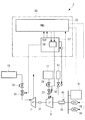
図1は、本実施形態にかかる発電システムのタービン発電機系統1の概略構成を示す。本実施形態では、メインエンジン3として船舶推進用のディーゼルエンジンを用いている。
タービン発電機系統1は、メインエンジン3と、メインエンジン3の排ガスによって駆動される過給機5と、過給機5の上流側から抽気されたメインエンジン3の排ガスによって駆動されるパワータービン(ガスタービン)7と、メインエンジン3の排ガスによって蒸気を生成する排ガスエコノマイザ11と、排ガスエコノマイザ11によって生成された蒸気(高圧蒸気)によって駆動される蒸気タービン9とを備えている。
FIG. 1 shows a schematic configuration of a
The
メインエンジン3からの出力は、プロペラ軸を介してスクリュープロペラに直接的または間接的に接続されている。また、メインエンジン3の各気筒のシリンダ部13の排気ポートは排ガス集合管としての排気マニホールド15に接続され、排気マニホールド15は、第1排気管L1を介して過給機5のタービン部5aの入口側と接続され、また、排気マニホールド15は第2排気管L2(抽気通路)を介してパワータービン7の入口側と接続されて、排ガスの一部が、過給機5に供給される前に抽気されてパワータービン7に供給されるようになっている。
The output from the
一方、各シリンダ部13の給気ポートは給気マニホールド17に接続されており、給気マニホールド17は、給気管K1を介して過給機5のコンプレッサ部5bと接続している。また、給気管K1には空気冷却器(インタークーラ)19が設置されている。
過給機5は、タービン部5aと、コンプレッサ部5bと、タービン部5aとコンプレッサ部5bを連結する回転軸5cとから構成されている。
On the other hand, the air supply port of each
The
パワータービン7は、第2排気管L2を介して排気マニホールド15から抽気された排ガスによって回転駆動されるようになっており、また、蒸気タービン9は、排ガスエコノマイザ11によって生成された蒸気が供給されて回転駆動されるようになっている。
この排ガスエコノマイザ11は、過給機5のタービン部5aの出口側から第3排気管L3を介して排出される排ガスと、パワータービン7の出口側から第4排気管L4を介して排出される排ガスとが、導入されて熱交換部21によって、排ガスの熱によって給水管23によって供給された水を蒸発させて蒸気を発生させる。そして、排ガスエコノマイザ11で生成された蒸気は第1蒸気管J1を介して蒸気タービン9に導入され、また、該蒸気タービン9で仕事を終えた蒸気は第2蒸気管J2によって排出されてコンデンサ(復水器)40に導かれるようになっている。
また、第1蒸気管J1には、蒸気タービン9へ向かう蒸気を取り出して復水器40へと導く蒸気ダンプ配管J3が設けられている。蒸気ダンプ配管J3には、蒸気ダンプ配管J3から復水器40へ導かれる蒸気量を制御するダンプ弁41が設けられている。この蒸気ダンプ配管J3によって、蒸気タービン9に供給するには過剰とされる蒸気が蒸気タービン9をバイパスして復水器40へと廃棄される。
The
The
Further, the first steam pipe J1 is provided with a steam dump pipe J3 that takes out the steam toward the
パワータービン7と蒸気タービン9とは直列に結合されてタービン発電機25を駆動するようになっている。蒸気タービン9の回転軸29は図示しない減速機及びカップリングを介してタービン発電機25に接続し、また、パワータービン7の回転軸27は図示しない減速機及びクラッチ31を介して蒸気タービン9の回転軸29と連結されている。クラッチ31としては、所定の回転数にて嵌脱されるクラッチが用いられ、例えばSSS(Synchro Self Shifting)クラッチが好適に用いられる。なお、本実施形態においては、パワータービン7と蒸気タービン9とを直列に結合してタービン発電機25を駆動するようにしているが、パワータービン7と蒸気タービン9とを並列に結合し、それぞれの回転動力から減速機を介してタービン発電機25を駆動するようにしてもよい。
The
また、第2排気管L2には、パワータービン7に導入するガス量を制御する排ガス量調整弁33と、非常時にパワータービン7への排ガスの供給を遮断する非常停止用緊急遮断弁35とが設けられている。なお、排ガス量調整弁33は、ガバナ制御機能を有しているものではない。すなわち、パワータービン7は、ガバナ制御されていない。
In the second exhaust pipe L2, there are also provided an exhaust gas
さらに、第1蒸気管J1には、蒸気タービン9に導入する蒸気量を制御する調速弁(蒸気量調整弁)37と、非常時に蒸気タービン9への蒸気の供給を遮断する非常停止用緊急遮断弁39とが設置されている。調速弁37は、発電システム制御装置43のガバナ59によって、その開度が制御される。
以上のようにタービン発電機系統1は、メインエンジン3の排ガス(燃焼ガス)の排気エネルギーを動力として駆動されるようになっており、排気エネルギー回収装置を構成している。
Furthermore, the first steam pipe J1 includes a control valve (steam volume adjustment valve) 37 that controls the volume of steam introduced to the
As described above, the
図2には、図1に示したタービン発電機系統1を有する発電システム2の概略構成が示されている。
FIG. 2 shows a schematic configuration of a
発電システム2は、タービン発電機系統1(図1参照)に加え、船内に別途設置された複数(本実施形態では2台)のディーゼルエンジン発電機(発電機)60を備えている。
The
そして、本実施形態に係る発電システム2の制御装置である発電システム制御装置43は、調速弁37の開度が一定(目標開度)となるように制御することで、蒸気タービン9に導入する蒸気圧を変化させる変圧運転を行う。
発電システム制御装置43には、タービン発電機25の出力電力を検出する電力センサ45からの信号が入力されている。また、発電システム制御装置43には、ディーゼルエンジン発電機60からの出力信号と、船内消費電力を検出する船内消費電力センサ51からの信号とが入力されている。
The power generation
A signal from a
また、発電システム制御装置43は、PMS(Power Management System;パワーマネジメントシステム)53と、TCP(Turbine Control Panel;タービンコントロールパネル)57と、ディーゼルエンジン発電機60用ガバナ部(図3のガバナ87,88)とを備えている。また、TCP57は、ガバナ59を備えている。ガバナ59は、蒸気タービン9の回転速度を制御するものであり、PMS53が指示する回転速度の速度設定に応じた調速弁37の開度を調速弁37に対し出力することで、蒸気タービン9の出力を制御する。
PMS53から設定された負荷率に応じた出力の指示信号が、TCP57、及びディーゼルエンジン発電機60用ガバナ部にそれぞれ出力される。
Further, the power generation
Output instruction signals according to the load factor set from the
PMS53から指示された蒸気タービン9の出力負担割合に応じて制御信号がTCP57のガバナ59に出力され、ガバナ59はそれに応じた調速弁37の開度を調速弁37へ出力し、調速弁37の開度が制御されて蒸気タービン9に供給される蒸気量が制御される。
ここで、パワータービン7と蒸気タービン9とタービン発電機25は1つの軸に直列に結合されている。このように各々が1つの軸に直列接続されている場合、ガバナは主となる原動機である蒸気タービン9に対するガバナ59のみが設置される。これは、1つの軸に2以上のガバナを設置するのは制御が複雑となるためである。
よって、パワータービン7による出力が変化する場合、発電システム制御装置43は、蒸気タービン9の出力、すなわちガバナ59によって調速弁37を制御することとなる。
ここで、パワータービン7にはガバナが設置されないため、パワータービン7の制御は排ガス量調整弁33の開閉のみの制御となり、定常運転中は常に全開のままとなる。但し、パワータービン7の立ち上げ及び立ち下げ時に限り、排ガス調整弁33の開度は漸増または漸減する。よって、パワータービン7の出力に変化があると蒸気タービン9の出力、すなわちガバナ59による調速弁37の開度制御がその変化量を吸収するように変動する。なお、パワータービン7の立ち上げとは、パワータービン7の出力が0である状態を起点として、出力を増加させることであり、パワータービン7の立ち下げとは、パワータービン7の出力が0になるように、出力を減少させることであると定義する。
A control signal is output to the
Here, the
Therefore, when the output from the
Here, since the governor is not installed in the
また、蒸気タービン9の中間段へは、低圧蒸気源61から混気蒸気(低圧蒸気)が供給される。混気蒸気の供給ライン上には、蒸気タービン9に導入する混気蒸気量を制御する調整弁62が設置されている。調整弁62の開度は、低圧蒸気源61での蒸気の発生量の増加及び減少に伴い、増加または減少する。よって、混気蒸気の供給量に変化があると蒸気タービン9の出力、すなわちガバナ59による調速弁37の開度制御がその変化量を吸収するように変動する。低圧蒸気源61としては排ガスエコノマイザ11の低圧段(図1参照)が挙げられる。
In addition, mixed steam (low pressure steam) is supplied from the low
以上のように、PMS53から調速弁37を操作するガバナ59に対し出力負担割合に応じた制御信号が出力される。
As described above, the control signal according to the output load ratio is output from the
次に、本実施形態に係るガバナ制御について説明する
本実施形態に係るガバナ制御では、TCP57によって、タービン発電機25で利用可能な蒸気タービン9の出力を示す負荷容量の制限値(以下「制限負荷容量値」という。)、及び調速弁37の目標開度と調速弁37の実際の開度との偏差に基づいて、蒸気タービン9から得られる実際の負荷容量値を算出する。そして、算出された負荷容量値に基づいて、ガバナ59によって調速弁開度が制御される。なお、調速弁37の目標開度は例えば90%の開度であり、必ずしも全開である必要はない。
Next, the governor control according to the present embodiment will be described. In the governor control according to the present embodiment, a limit value of the load capacity indicating the output of the
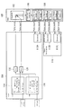
図3を参照して、本実施形態に係るガバナ制御について詳細に説明する。図3は、本実施形態に係るTCP57及びPMS53のガバナ制御に係る機能ブロック図である。
The governor control according to the present embodiment will be described in detail with reference to FIG. FIG. 3 is a functional block diagram relating to governor control of the
TCP57は、PMS53へ出力する負荷容量値を算出する負荷容量値算出部70を備える。負荷容量値算出部70は、従来のように、PMS53に予め保持されている負荷容量値を増減させるパルス信号をPMS53へ出力するのではなく、負荷容量値の絶対値を算出し、アナログ信号(電圧値)としてPMS53へ出力する。
The
負荷容量値算出部70は、制限負荷容量値を算出する制限値算出部71を備える。
制限値算出部71は、例えば、メインエンジン3の負荷(M/E Load)に基づいて負荷容量値の制限値(以下「制限負荷容量値」という。)を算出し、乗算部72へ出力する。制限負荷容量値は、換言すると、算出される負荷容量値の上限値である。すなわち、負荷容量値算出部70で算出される負荷容量値には、上限値が定められる。このように、負荷容量値算出部70は、負荷容量値に上限が定めるので、現実に則した負荷容量値を算出することとなる。
なお、制限値算出部71は、一例として、メインエンジン3の負荷と外気温度(Atomos.Temp.)を変数とする予め定められた関数によって、理論上求められる制限負荷容量値を算出する。理論上求められる制限負荷容量値は、換言すると、負荷容量値の設計値である。しかしながら、制限負荷容量値は、これに限らず、この設計値に対して他のパラメータを加味して、より現実に則したものとされてもよい。
The load capacity
For example, the limit
The limit
また、TCP57は、減算部73及びPID演算部74を備える。
減算部73は、調速弁37の目標開度(GV lift Setting)と調速弁37の実際の開度(GV Lift)との偏差である開度偏差を算出し、PID演算部74へ出力する。
PID演算部74は、開度偏差に基づいて負荷容量値(以下「開度偏差負荷容量値」という。)を演算し、低値選択部75へ出力される。なお、PID演算部74は、開度偏差を変数とする予め定められた関数によって、開度偏差負荷容量値を算出する。
開度偏差負荷容量値は、低値選択部75において、蒸気タービン9に導入する蒸気圧の設定値と実際の蒸気圧との偏差に基づく負荷容量値(以下「圧力偏差負荷容量値」という。)と比較され、より小さい値が低値選択部75から出力される。低値選択部75から出力される負荷容量値は、換言すると、負荷容量の目標値(以下「負荷容量目標値」という。)である。
The
The
The opening deviation load capacity value is referred to as a load capacity value (hereinafter referred to as “pressure deviation load capacity value”) based on the deviation between the set value of the steam pressure introduced to the
低値選択部75から出力された負荷容量目標値は、減算部76を介してPID演算部77に入力される。
The load capacity target value output from the low
減算部76は、負荷容量目標値を乗算部72から出力された負荷容量値で減算し、減算値をPID演算部77へ出力する。すなわち、乗算部72から出力される値は、負荷目標値の現在値であり、減算部76では負荷容量の目標値と現在値との偏差が算出される。
The subtracting
PID演算部77は、入力された偏差を1以下の値となるように演算し、乗算部72へ出力する。すなわち、算出される負荷容量値が制限負荷容量値を超えないように、負荷容量の目標値と現在値との偏差がPID演算部77で1以下とされ、乗算部72で制限負荷容量値と乗算される。
The
このように、負荷容量値算出部70は、調速弁37の目標開度と調速弁37の実際の開度との偏差に基づいて、制限負荷容量値を上限とした負荷容量値を算出する。
As described above, the load capacity
なお、本実施形態に係る蒸気タービン9は、高圧蒸気と低圧蒸気とが導入されるが、低圧蒸気に関してはガバナ制御がされていない。このため、乗算部72から出力される負荷容量値は、別途算出された低圧蒸気に基づく負荷容量値(LP Avail.kW)と加算部78で加算される。加算部78から出力される負荷容量値は、本実施形態に係る蒸気タービン9の負荷容量値(ST Avail.kW)である。
また、本実施形態に係るタービン発電機系統1は、パワータービン7も備えているため、別途算出されたパワータービン7の出力値(PT Act.kW)も加算部79で更に加算される。すなわち、加算部79から出力された負荷容量値が、本実施形態に係るタービン発電機25の実際の負荷容量値(STG Avail.kW)の絶対値であり、この値がアナログ信号(電圧値)としてPMS53が備える負荷分担制御部80へ出力される。
In the
Further, since the
また、本実施形態に係る負荷容量値算出部70は、前述のように、開度偏差負荷容量値と圧力偏差負荷容量値のうちより小さな値を、蒸気タービン9から得られる実際の負荷容量値(負荷容量目標値)として算出する。
この理由は、調速弁開度が開くほど蒸気圧は低下するが、蒸気圧には最小値が設定されているため、実際の蒸気圧が設定最小値未満とならないようにするためである。すなわち、圧力偏差負荷容量値が開度偏差負荷容量値よりも小さい場合とは、実際の蒸気圧が設定最小値未満となる場合である。このような場合には、圧力偏差負荷容量値が低値選択部75で選択され、実際の蒸気圧を設定最小値以上に維持することができる負荷容量値が算出される。
これにより、蒸気タービン9に導入する蒸気圧が設定最小値未満となることを防止できる。
In addition, as described above, the load capacity
The reason for this is that although the vapor pressure decreases as the degree of control valve opening increases, the vapor pressure is set to a minimum value so that the actual vapor pressure does not fall below the set minimum value. That is, when the pressure deviation load capacity value is smaller than the opening degree deviation load capacity value, the actual steam pressure is less than the set minimum value. In such a case, the pressure deviation load capacity value is selected by the low
This can prevent the steam pressure introduced to the
そこで、負荷容量値算出部70は、圧力偏差負荷容量値を算出するために、減算部81及びPID演算部82を備える。
減算部81は、高圧蒸気圧の計測値(HP Press)と高圧蒸気圧の設定最小値(HP Press Min Setting)との偏差である圧力偏差を算出し、PID演算部82へ出力する。
PID演算部82は、圧力偏差に基づいて圧力偏差負荷容量値を演算し、低値選択部75へ出力する。なお、PID演算部82は、圧力偏差を変数とする予め定められた関数によって、圧力偏差負荷容量値を算出する。
Therefore, the load capacity
The
The
また、実際の蒸気圧と設定最小値との偏差が大きすぎると、算出される負荷容量値の時間変化も大きくなり、このような負荷容量値を用いてガバナ制御を行うとタービン発電機系統1が大きく変化し、制御が不安定となる可能性がある。制御が不安定となる原因は、蒸気タービン9の調速弁37の開度を急激に開けると、高圧蒸気圧が急激に低下し、高圧ドラム(不図示)と排ガスエコノマイザ11との間である高圧蒸発部間に水を循環させている循環水ポンプ(不図示)がキャビテーションを起こす可能性があるためである。高圧ドラム(及び循環水ポンプ吸込み配管)では水(液体)の温度に比べて圧力が急に下がると水が蒸発して循環水ポンプの吸込みでキャビテーションを生じる可能性がある。
これを防止するために、負荷容量値算出部70は、減算部83、高値選択部84、及びレートリミッタ85を備える。
In addition, if the deviation between the actual steam pressure and the set minimum value is too large, the time change of the calculated load capacity value also increases. When governor control is performed using such a load capacity value, the
In order to prevent this, the load capacity
減算部83は、高圧蒸気圧の計測値に対して予め定められた変動抑制値(規制値)を減算する。変動抑制値は、例えば0.5barである。
高値選択部84は、変動抑制値で減算された計測値と設定最小値とを比較し、より小さな値をレートリミッタ85へ出力する。
レートリミッタ85は、高値選択部84から出力された値を所定の時間変化率で減算部83へ出力する。
The
The high
The
ここで、高圧蒸気圧の計測値が例えば6.2barであり、設定最小値が例えば5.5barの場合、高値選択部84から出力される値は5.7barとなり、減算部81から出力される値は0.5barとなる。また、高圧蒸気圧の計測値が例えば5.8barであり、設定最小値が例えば5.5barの場合、高値選択部84から出力される値は5.5barとなり、減算部81から出力される値は0.3barとなる。一方、高圧蒸気圧の計測値が8.0barの場合でも、高値選択部84から出力される値は7.5barとなるため、減算部81から出力される値は0.5barとなる。すなわち、本実施形態に係る負荷容量値算出部70は、高圧蒸気圧の計測値と設定最小値との偏差が大きくても、変動抑制値を超えた偏差を用いることなく、すなわち変動抑制値を規制値とし、変動抑制値以下の値で負荷容量値を算出する。これにより、負荷容量値算出部70によって算出される負荷容量値の時間変化が大きく変化することが抑制される。
Here, when the measured value of the high pressure steam pressure is, for example, 6.2 bar and the set minimum value is, for example, 5.5 bar, the value output from the high
このようにしてTCP57で算出された負荷容量値(STG Avail.kW)は、アナログ信号(電圧値)としてPMS53へ出力される。
The load capacity value (STG Avail. KW) calculated by the
PMS53は、負荷分担制御部80及びガバナ増減パルス生成部86を備える。
負荷分担制御部80は、TCP57から入力された負荷容量値に基づいて、蒸気タービン9及びディーゼルエンジン発電機60の負荷分担を示す負荷分担信号を生成する。ガバナ増減パルス生成部86は、負荷分担制御部80からの負荷分担信号に基づいて、蒸気タービン9及びディーゼルエンジン発電機60に対して、制御値(速度設定値)を増加又は減少させるためのガバナ増又はガバナ減を示すパルス信号(以下「ガバナ増減パルス信号」という。)を生成し、各々に対応するガバナ59,87,88へ出力する。
The
The load
なお、ガバナ59は、TCP57に備えられ、蒸気タービン9の回転速度を制御するものであり、PMS53が指示する回転速度の速度設定値(ガバナ増減パルス信号)に応じた調速弁開度を調速弁37へ出力することで、蒸気タービン9の出力を制御すると共に、調速弁開度が目標開度となるように制御される。
また、ガバナ87,88は、各々対応するディーゼルエンジン発電機60に備えられ、ディーゼルエンジン発電機60の回転速度を制御するものであり、PMS53が指示する回転速度の速度設定値(ガバナ増減パルス信号)に応じた調速弁開度を調速弁37へ出力することで、ディーゼルエンジン発電機60の出力を制御する。
The
Further, the
次に、パワータービン7の出力値(PT Act.kW)の算出について説明する。
Next, calculation of the output value (PT Act. KW) of the
タービン発電機25の負荷容量値(STG Avail.kW)は、上述したように蒸気タービン9の負荷容量値(ST Avail.kW)とパワータービン7の出力値(PT Act.kW)との和である((1)式)。
STG Avail.kW=ST Avail.kW+PT Act.kW ・・・(1)
The load capacity value (STG Avail.kW) of the
STG Avail. kW = ST Avail. kW + PT Act. kW (1)
ここで、パワータービン7の出力値(PT Act.kW)は、(2)式に示されるように、タービン発電機25の出力計測値(STG Act.kW)から蒸気タービン9の出力計測値(ST Act.kW)を減算することで算出される。
PT Act.kW=STG Act.kW−ST Act.kW ・・・(2)
なお、蒸気タービン9の出力計測値は、蒸気タービン9に導入される主蒸気圧力、蒸気温度、蒸気の排気圧力等の各種計測値を用いて既知の手法により算出される。
Here, the output value (PT Act. KW) of the
PT Act. kW = STG Act. kW-ST Act. kW (2)
The output measurement value of the
さらに、タービン発電機25の負荷容量値(STG Avail.kW)を(1)式に基づいて算出する理由を以下に詳述する。
タービン発電機25の負荷容量値(STG Avail.kW)は、パワータービン7の負荷容量値(PT Avail.kW)を用いて下記(3)式から算出することも考えられる。
STG Avail.Kw=ST Avail.kW+PT Avail.kW ・・・(3)
ここで、パワータービン7の負荷容量値(PT Avail.kW)は、メインエンジン3の負荷による関数に対して、外気温(過給機5の吸込み温度)をパラメータとして補正することで求められる。すなわち、(3)式では、メインエンジン3の負荷と外気温とでパワータービン7の負荷容量値(PT Avail.kW)がある値に決まってしまうので、メインエンジン3の負荷と外気温とでは、パワータービン7の起動中において時々刻々と変化するパワータービン7の負荷容量値(PT Avail.kW)を算出できない。従って、(3)式では、パワータービン7の起動中におけるタービン発電機25の負荷容量値(STG Avail.kW)も算出できない。
Further, the reason why the load capacity value (STG Avail.kW) of the
The load capacity value (STG Avail. KW) of the
STG Avail. Kw = ST Avail. kW + PT Avail. kW (3)
Here, the load capacity value (PT Avail.kW) of the
なお、起動中における実際のパワータービン7の出力値の変化に近づくように予想して、パワータービン7の負荷容量値(PT Avail.kW)を徐々に変化させる方法も考えられる。しかしながら、実際と予想に差があれば、この差分を蒸気タービン9の調速弁37が吸収しようと大きく動いてしまう可能性も考えられる。
It is also conceivable to gradually change the load capacity value (PT Avail.kW) of the
そこで、(1)式のようにパワータービン7の出力値(PT Act.kW)そのものを用いることによって、パワータービン7の起動中の負荷容量値の変化を精度良くタービン発電機25の負荷容量値(STG Avail.kW)にリアルタイムで反映できる。これにより、上述した様な、蒸気タービン9の調速弁37の開度が大きく動くという問題も生じない。
なお、蒸気タービン9の調速弁37の開度(換言すると、蒸気タービン9の出力)を現状維持することを目的とすると、パワータービン7の起動中の出力値(PT Act.kW)の変化は、即ちタービン発電機25の負荷容量値(STG Avail.kW)の変化でもあると考えることができる。また、パワータービン7の起動中の出力の変化は、(2)式で算出されるPT Act.kWの変化として現れ、精度良く得られる。
Therefore, by using the output value (PT Act. KW) itself of the
Note that, for the purpose of maintaining the opening degree of the
図4は、負荷容量値算出部70におけるパワータービン7の出力値の算出に関する機能ブロック図の一例である。
FIG. 4 is an example of a functional block diagram regarding calculation of the output value of the
負荷容量値算出部70は、減算部90、減算部91、及びPID演算部92を備える。
減算部90は、タービン発電機25の出力計測値(STG Act.kW)から蒸気タービン9の出力計測値(ST Act.kW)を減算し、パワータービン7の出力値(PT Act.kW)を算出する。
減算部91は、減算部90からの出力値(PT Act.kW)とPID演算部92から出力されるパワータービン7の負荷容量値とを減算し、偏差を出力する。なお、減算部91から出力される偏差が0でない場合は、パワータービン7の出力に変化があった場合である。
PID演算部92は、減算部91から出力された偏差に基づいて、パワータービン7の負荷容量値を算出し、加算部79へ出力する。なお、PID演算部92は、パワータービン7の出力に変化があり、大きな値の偏差が入力された場合に、パワータービン7の出力値を急激に変化させるのではなく、パワータービン7の出力値(負荷容量値)を時間変化を伴って徐々に変化させて出力する。
The load capacity
The
The
このようにしてパワータービン7の出力値を算出することで、メインエンジン3の負荷が変化している場合におけるパワータービン7の出力の変化が絶対値(アナログ信号)として現れる。
By calculating the output value of the
ここで、パルス信号を用いた従来の制御では、蒸気タービン9の調速弁37がパワータービン7の出力変化に応じて、また、PMS53における負荷容量値の変化に応じてその都度制御されるので、プラントの状態が変化している間に、調速弁開度が過度に低下したり、全開位置で固定されたりすることで、制御が不安定になる可能性があった。
Here, in the conventional control using a pulse signal, the
一方、本実施形態では、パワータービン7の出力変化がタービン発電機25の負荷容量値にリアルタイムで反映される。このため、PMS53は、パワータービン7の出力が変化しても、算出した負荷容量値(STG Avail.kW)を用いて船内の各発電機の負荷分担を時間遅れ無く算出し、各発電機に調速弁開度の増加又は減少を示す指令(ガバナ増減パルス信号)を出力することができる。すなわち、パワータービン7の出力が変化しても、算出したタービン発電機25の負荷容量値を時間遅れ無く算出できるので、調速弁開度の制御を安定化できる。さらに、パワータービン7の出力が変化しても、調速弁開度は大きく変化せずに、より安定した制御が可能となる。
On the other hand, in the present embodiment, the change in output of the
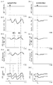
次に、本実施形態に係るタービン発電機系統1の変圧運転について、具体的に図5〜8を参照して説明する。
Next, the transformation operation of the
図5は、変圧運転における各種制御値の時間変化を示すグラフであり、図5(A)はメインエンジン3の負荷の時間変化、図5(B)は蒸気タービン9の調速弁開度の時間変化(実線)及びダンプ弁41の開度の時間変化(破線)、図5(C)は高圧蒸気圧の時間変化、図5(D)はタービン発電機25の出力の時間変化を示す。なお、図5の横軸(時間)は、期間(1)〜(14)とのように便宜的に分けられる。
FIG. 5 is a graph showing the time change of various control values in the transformer operation, FIG. 5 (A) is the time change of the load of the
まず、メインエンジン3の負荷が増加する場合について、期間(1)〜(8)毎に説明する。
First, the case where the load on the
期間(1):メインエンジン3の起動が開始され、排ガスエコノマイザ11が起動して高圧蒸気の生成が開始され昇圧される。
Period (1): Start of the
期間(2):高圧蒸気圧がダンプ弁41の設定圧まで昇圧するとダンプ弁41が開き、蒸気量の増加に伴いダンプ弁41の開度が高圧蒸気圧を一定圧とするように制御される。
Period (2): When the high pressure steam pressure rises to the set pressure of the
期間(3):蒸気タービン9が起動を開始する。そして、調速弁37の開度増加に連れ、又は負荷の増加に連れ、蒸気タービン9へ蒸気が導入される。これに伴い、ダンプ弁41の開度が減少し、やがてダンプ弁41が全閉となる。すなわち、期間(1)から期間(3)までの間は、高圧蒸気圧はダンプ弁41によって制御される。
そして、期間(3)までは、高圧蒸気圧は設定最小値を超え、また、調速弁開度は目標開度未満であるため、TCP57はPMS53へ出力する負荷容量値を増加させる。
PMS53は増加した負荷容量値に応じてガバナ59にガバナ増指令を示すパルス信号を出力し、これによりガバナ59が調速弁開度を増加するので、蒸気タービン9の負荷が増加する。
Period (3): The
Until the period (3), the high pressure steam pressure exceeds the set minimum value, and the speed control valve opening is less than the target opening, so the
The
期間(4):ダンプ弁41が全閉とされ、調速弁開度が増加するに連れて高圧蒸気圧が低下する。なお、期間(4)におけるTCP57及びPMS53の動作、並びに負荷容量値の変化は期間(3)と同様である。
Period (4): The
期間(5):調速弁開度を目標開度となるように増加させる間に、高圧蒸気圧が低下して設定最小値に達すると、設定最小値を維持するように調速弁開度が制御される。そして、蒸気量の増加に連れて、設定最小値を維持しながら調速弁開度が増加する。
なお、高圧蒸気圧が設定最小値未満となると、調速弁開度が目標開度に達していなくても、TCP57はそれまでのような負荷容量値の増加をやめ、設定最小値を維持すべく負荷容量値を調整する。
Period (5): While the control valve opening degree is increased to the target opening degree, when the high pressure steam pressure decreases and reaches the set minimum value, the control valve opening degree is maintained so as to maintain the set minimum value Is controlled. Then, as the amount of steam increases, the speed control valve opening increases while maintaining the set minimum value.
When the high-pressure steam pressure is less than the set minimum value, the
期間(6):調速弁開度が目標開度に達したら開度の制御は止まり、これ以降、蒸気量が増加すると調速弁37の目標開度を維持したままで高圧蒸気圧が増加していく。
なお、調速弁開度を目標開度とする制御は一旦止まるが、厳密にはこの状態で蒸気量が増加すると蒸気タービン9の回転速度が増加するので、ガバナ59は蒸気タービン9に導入する蒸気量を減少させるように動き、調速弁開度は減少する。そして、さらに調速弁開度を目標開度とするべくTCP57は負荷容量値を増加させ、PMS53のガバナ増指令により負荷が増加する。このように、調速弁37の目標開度到達後も蒸気量増加に伴い、調速弁開度を目標開度とする制御が繰り返されながら負荷容量値が増加し、蒸気タービン9の負荷が増加していく。
Period (6): When the speed control valve opening reaches the target opening, the control of the opening stops, and thereafter, when the amount of steam increases, the high pressure steam pressure increases while maintaining the target opening of the
Note that although the control to set the regulating valve opening to the target degree of opening temporarily stops, strictly speaking, if the amount of steam increases in this state, the rotational speed of the
期間(7):パワータービン7の起動が開始される。過渡的にはパワータービン7の出力の増加に伴い調速弁開度も変動するが、変動が大きくならないように負荷容量値を制御しているので、本図では省略している。
Period (7): The start of the
期間(8):メインエンジン3の負荷増加によるパワータービン7の出力増加と蒸気量増加に伴い、PMS53からガバナ増指令を受けるまで、調速弁開度は減少するように制御され、期間(6)と同様のような動きで負荷容量値、及び蒸気タービン9の負荷が増加していく。なお、調速弁開度が目標開度より減少すると、調速弁開度を目標開度に戻すためにTCP57はタービン発電機25の負荷容量値(STG Avail.kW)を増加させる。そしてPMS53からガバナ増指令を受けて調速弁開度は目標開度に向かって増加する。このように、期間(8)では、調速弁開度が小さな増減を繰り返しながら、目標開度を維持することとなる。
Period (8): The control valve opening degree is controlled to decrease until the governor increase command is received from
次にメインエンジン3の負荷が減少する場合について、期間(11)〜(14)毎に説明する。
Next, the case where the load of the
期間(11):メインエンジン3の負荷減少によるパワータービン7の出力増加と蒸気量の減少に伴い、PMS53からガバナ減指令を受けるまで、調速弁開度は蒸気タービン9の速度低下を補うべく増加方向に動く。一方、TCP57は、調速弁開度を目標開度に戻すべく負荷容量値を減少させ、PMS53のガバナ減指令により負荷が減少する。
なお、調速弁開度が目標開度より増加すると、調速弁開度を目標開度に戻すためにTCP57はタービン発電機25の負荷容量値(STG Avail.kW)を減少させる。そしてPMS53からガバナ減指令を受けて調速弁開度は目標開度に向かって減少する。このように、期間(11)では、調速弁開度が小さな増減を繰り返しながら、目標開度を維持することとなる。
Period (11): As the power reduction of the
When the speed control valve opening is increased from the target opening, the
期間(12): パワータービン7が停止する。通常、メインエンジン3の負荷減少による抽ガス許容量の低下によりパワータービン7が停止する。過渡的にはパワータービン7の出力の減少、そして停止に伴い調速弁開度も変動するが、変動が大きくならないように負荷容量値を制御しているので、本図では省略している。
Period (12): The
期間(13):さらなるメインエンジン3の負荷減少による蒸気量の低下に伴い、調速弁開度は、目標開度に維持されつつ、高圧蒸気圧が設定最小値まで低下する。その後、高圧蒸気圧の設定最小値を維持すべく負荷容量値を減少させるので調速弁開度が減少する。
Period (13): As the steam amount further decreases due to a decrease in the load on the
期間(14):負荷容量値が予め定めされた最小値に達すると、負荷容量値はそれ以上減少しなくなり、PMS53は上記最小値の負荷を保とうとしてガバナ59に指令(例えば増加指令)を与えるので、高圧蒸気圧が設定最小値よりも低下し始める。その後、出力の低下と高圧蒸気圧の低下に伴い蒸気タービン9が停止する。
Period (14): When the load capacity value reaches a predetermined minimum value, the load capacity value no longer decreases, and the
図6は、パワータービン7の起動時における従来の各種制御値の時間変化と、本発明の実施形態に係る各種制御値の時間変化を示すグラフである。なお、図6(A−1)〜(A−6)が従来の各種制御値の時間変化を示し、図6(B−1)〜(B−6)が本発明の実施形態に係る各種制御値の時間変化を示す。また、時間T1は排ガス量調整弁33を開けることによって、パワータービン7を起動させるタイミングを示し、時間T2はパワータービン7のクラッチ31をオンとしてパワータービン7がタービン発電機25に接続されるタイミングを示し、時間T3は本実施形態においてパワータービン7の出力が一定となったタイミングを示し、時間T4は排ガス量調整弁33が全開となったタイミングを示す。
FIG. 6 is a graph showing temporal changes of various conventional control values at the time of starting the
図6(A−1),(B−1)は、メインエンジン3の負荷の時間変化を示すものの、図6では一例として、メインエンジン3の負荷が一定の場合を示す。
6 (A-1) and (B-1) show the time change of the load of the
図6(A−2),(B−2)は、排ガス量調整弁33の開度の時間変化を示す。排ガス量調整弁33の開度は、時間T1から時間T4の間で全閉から全開まで連続的に変化する。
6 (A-2) and (B-2) show the time change of the opening degree of the exhaust gas
図6(A−3),(B−3)は、PMS53における負荷容量値(タービン発電機25の負荷容量値)の時間変化を示す。なお、従来に係る図6(A−3)では、負荷容量値はパルス信号により増減されるため、時間経過と共に段階的に増加している。一方、本実施形態に係る図6(B−3)では、負荷容量値はアナログ信号で表されるため、連続的に増加している。
従来のパルス信号を用いた負荷容量値の増加では、パワータービン7の出力が一定となった時間T3以降も時間遅れのために、段階的に負荷容量値が増している。一方、本実施形態に係る制御では、パワータービン7の出力が一定となった時間T3のタイミングで、負荷容量値の増加は終わり、その後一定となる。
6 (A-3) and (B-3) show time changes of the load capacity value (load capacity value of the turbine generator 25) in the
The increase in the load capacitance with a conventional pulse signal, for the time delay output time T 3 after became
図6(A−4),(B−4)は、蒸気タービン9に対するガバナ速度設定値の時間変化を示す。
ガバナ速度設定値の変化は、負荷容量値の増減に依存するため、従来に係る図6(A−4)では、パワータービン7の出力が一定となった時間T3以降も時間遅れのために、所定値ずつ段階的にガバナ速度設定値が増している。一方、本実施形態に係る図6(B−4)では、パワータービン7の出力が一定となった時間T3となったタイミングで、ガバナ速度設定値の増加は終わり、その後一定となる。
6 (A-4) and (B-4) show the time change of the governor speed setting value with respect to the
Change of governor speed setting value is dependent on the increase or decrease of load capacitance, in FIG. 6 according to prior art (A-4), for the time delay output becomes constant T 3 after the
図6(A−5),(B−5)は、調速弁開度の時間変化を示す。また、図6(A−6),(B−6)は、蒸気タービン9の出力及びパワータービン7の出力と共に、タービン発電機25の出力の時間変化を示す。
図6(A−5),(B−5)で示されるように、パワータービン7の出力が増加すると共に調速弁開度は減少する。これが期間aである。一方、減少し過ぎた調速弁開度を目標開度とする制御が、期間bで行われる。
従来では、パワータービン7の出力変化に伴い調速弁開度が制御され、その後パルス信号によってPMS53に保持している調速弁開度や蒸気圧を目標値とする制御が行われていた。このため、制御に時間遅れが生じており、排ガス量調整弁33が全開となってもパワータービン7や蒸気タービン9も整定状態となっていない。
一方、本実施形態では、(1)式で示すように、パワータービン7の出力変化がタービン発電機25の負荷容量値(アナログ信号)にリアルタイムで反映させるため、時間遅れ無く調速弁開度の制御が可能となり、減少し過ぎた調速弁開度を目標開度とする制御に要する時間(期間b)も従来に比べて短くなる。特に、本実施形態では、排ガス量調整弁33が全開となったタイミングにおいて、調速弁開度を目標開度とできるのでパワータービン7や蒸気タービン9も従来に比べて早く整定状態となる。
6 (A-5) and (B-5) show the change over time of the speed control valve opening. 6 (A-6) and (B-6) show the time change of the output of the
As shown in FIGS. 6 (A-5) and (B-5), as the output of the
In the related art, the control valve opening degree is controlled in accordance with the output change of the
On the other hand, in the present embodiment, as indicated by the equation (1), the change in the output of the
図7は、パワータービン停止時における従来の各種制御値の時間変化と、本発明の実施形態に係る各種制御値の時間変化を示すグラフである。なお、図7(A−1)〜(A−6)が従来の各種制御値の時間変化を示し、図7(B−1)〜(B−6)が本発明の実施形態に係る各種制御値の時間変化を示す。また、時間T5は排ガス量調整弁33を閉めるタイミングを示し、時間T6はパワータービン7のクラッチ31をオフとしてパワータービン7がタービン発電機25に非接続とされるタイミングを示し、時間T7は排ガス量調整弁33が全閉となったタイミングを示す。
FIG. 7 is a graph showing the time change of various conventional control values when the power turbine is stopped and the time change of various control values according to the embodiment of the present invention. 7 (A-1) to (A-6) show the time change of the conventional various control values, and FIGS. 7 (B-1) to (B-6) show various controls according to the embodiment of the present invention. Indicates the time change of the value. The time T 5 represents the timing of closing the exhaust gas
図7(A−1),(B−1)は、メインエンジン3の負荷の時間変化を示すものの、図7では一例として、メインエンジン3の負荷が一定の場合を示す。
7A-1 and 7B-1 show the time change of the load of the
図7(A−2),(B−2)は、排ガス量調整弁33の開度の時間変化を示す。排ガス量調整弁33の開度は、時間T5から時間T7の間で全開から全閉まで連続的に変化する。
7 (A-2) and (B-2) show the time change of the opening degree of the exhaust gas
図7(A−3),(B−3)は、PMS53における負荷容量値(タービン発電機25の負荷容量値)の時間変化を示す。なお、従来に係る図7(A−3)では、負荷容量値はパルス信号により増減されるため、段階的に減少している。なお、図7(A−3)では、パルス信号による負荷容量値の増減の時間遅れにより、タービン発電機25の負荷容量値は過度に減少し、その後に増加に転じて一定となる。
一方、本実施形態に係る図7(B−3)では、負荷容量値はアナログ信号で表されるため、連続的に減少し、時間遅れもない。
7 (A-3) and (B-3) show the time change of the load capacity value (load capacity value of the turbine generator 25) in the
On the other hand, in FIG. 7 (B-3) according to the present embodiment, since the load capacitance value is represented by an analog signal, it continuously decreases and there is no time delay.
図7(A−4),(B−4)は、蒸気タービン9に対するガバナ速度設定値の時間変化を示す。
ガバナ速度設定値の変化は、負荷容量値の増減に依存するため、従来に係る図7(A−4)では、ガバナ速度設定値が減少した後に増加して一定となる。一方、本実施形態に係る図7(B−4)では、従来のようなガバナ速度設定値の減少・増加はなく、ガバナ速度設定値は減少後に一定となる。
7 (A-4) and (B-4) show the time change of the governor speed setting value with respect to the
Since the change of the governor speed setting value depends on the increase and decrease of the load capacity value, in FIG. 7 (A-4) according to the related art, the governor speed setting value decreases and then becomes constant. On the other hand, in FIG. 7 (B-4) according to the present embodiment, there is no decrease / increase of the governor speed set value as in the prior art, and the governor speed set value becomes constant after the decrease.
図7(A−5),(B−5)は、調速弁開度の時間変化を示す。また、図7(A−6),(B−6)は、蒸気タービン9の出力及びパワータービン7の出力と共に、タービン発電機25の出力の時間変化を示す。
従来では、制御に時間遅れが生じているので、タービン発電機25の出力は正定状態となるまで時間を要する。一方、本実施形態では、時間遅れ無く制御が可能でるため、タービン発電機25の出力が正定状態となるまでの時間が従来に比べて短い。
FIG. 7 (A-5) and (B-5) show the time change of the speed control valve opening. 7 (A-6) and (B-6) show the time change of the output of the
Conventionally, since a time delay has occurred in the control, it takes time for the output of the
図8は、船内電力負荷の増加時における従来の各種制御値の時間変化と、本発明の実施形態に係る各種制御値の時間変化を示すグラフである。なお、図8(A−1)〜(A−5)が従来の各種制御値の時間変化を示し、図8(B−1)〜(B−5)が本発明の実施形態に係る各種制御値の時間変化を示す。また、時間T10は船内電力負荷が増加したタイミングを示す。 FIG. 8 is a graph showing temporal changes in various conventional control values when the inboard power load increases, and temporal changes in various control values according to the embodiment of the present invention. 8 (A-1) to (A-5) show the time change of the conventional various control values, and FIGS. 8 (B-1) to (B-5) show various controls according to the embodiment of the present invention. Indicates the time change of the value. The time T 10 indicates the timing of ship power load increases.
図8(A−1),(B−1)は、メインエンジン3の負荷の時間変化を示すものの、図8では一例として、メインエンジン3の負荷が一定の場合を示す。
8A-1 and 8B-1 show the time change of the load of the
図8(A−2),(B−2)は調速弁開度の時間変化を示し、図8(A−3),(B−3)はPMS53における負荷容量値(タービン発電機25の負荷容量値)の時間変化を示し、図8(A−4),(B−4)は蒸気タービン9に対するガバナ速度設定値の時間変化を示し、図8(A−5),(B−5)は、蒸気タービン9の出力及びパワータービン7の出力と共に、タービン発電機25の出力の時間変化を示す。
8 (A-2) and (B-2) show the time change of the degree of control valve opening, and FIGS. 8 (A-3) and (B-3) show the load capacity value in PMS 53 (
時間T10で船内電力負荷が増加すると、それに伴い、調速弁開度は増加し、タービン発電機25の出力も増加する。一方、調速弁開度が増加するので調速弁開度を目標開度とするべく負荷容量値は減少する。この負荷容量値の変化に応じて、ガバナ速度設定値及びタービン発電機25の出力値も変化する。
ここで、従来では、PMS53に保持されている負荷容量値をパルス信号によって増減させるため、タービン発電機25の出力変化に対して負荷容量値の変化に遅れが生じる。その結果、ガバナ速度設定値や調速弁開度の変化にも遅れが生じるので、図8(A−2)〜(A−5)に示されるように、各種制御値にハンチングが生じる可能性がある。換言すると、パルス信号による負荷容量値の変化の位相が、タービン発電機25の出力、ガバナ速度設定値や調速弁開度の変化の位相とずれるため、ハンチングが生じる可能性がある。
一方、本実施形態では、TCP57で負荷容量値の絶対値を算出し、アナログ信号によりPMS53へ出力するので、負荷容量値の算出、ガバナ速度設定値の出力、調速弁開度の制御を時間遅れ無く行えるので、従来のようなハンチングを抑制できる。
When ship power load increases at time T 10, accordingly, the governor valve opening increases and also increases the output of the
Here, in the related art, since the load capacity value held in the
On the other hand, in this embodiment, since the absolute value of the load capacity value is calculated by the
以上説明したように、本実施形態に係るTCP57は、調速弁37の開度を一定(目標開度)となるように制御することで、蒸気タービン9に導入する蒸気圧を変化させる変圧運転を行う。そして、TCP57は、調速弁37の目標開度と調速弁37の実際の開度との偏差に基づいて、蒸気タービン9から得られる実際の負荷容量値を算出す、算出した負荷容量値に基づいて調速弁開度を制御する。
これにより、本実施形態に係るTCP57は、調速弁開度の制御に用いる負荷容量値を従来のようにパルス信号で増減しないので、パルス信号特有の時間遅れを生じることなく、調速弁37を制御できる。従って、TCP57は、プラントの状態が変化した場合の排熱回収において、より安定な制御を可能とする。
As described above, the
As a result, the
以上、本発明を、上記実施形態を用いて説明したが、本発明の技術的範囲は上記実施形態に記載の範囲には限定されない。発明の要旨を逸脱しない範囲で上記実施形態に多様な変更又は改良を加えることができ、該変更又は改良を加えた形態も本発明の技術的範囲に含まれる。 As mentioned above, although this invention was demonstrated using the said embodiment, the technical scope of this invention is not limited to the range as described in the said embodiment. Various changes or improvements can be added to the above-described embodiment without departing from the gist of the invention, and embodiments to which the changes or improvements are added are also included in the technical scope of the present invention.
例えば、上記実施形態では、本実施形態に係るタービン発電機系統1が舶用の発電システムとして用いられる形態について説明したが、本発明は、これに限定されるものではなく、本実施形態に係るタービン発電機系統1は、例えば陸上のプラント設備に適用される形態としてもよい。
この形態の場合、プラント設備は、無限大母線と接続されていない、所謂マイクログリッド(アイランドモードともいう。)で運用される。
For example, although the above-mentioned embodiment explained the form by which
In the case of this form, the plant equipment is operated in a so-called microgrid (also referred to as an island mode) that is not connected to an infinite bus.
また、上記実施形態では、一例として、排ガスがメインエンジン3によって生成される形態について説明したが、本発明は、これに限定されるものではなく、排ガスをメインエンジン3以外で生成される排ガス、例えば、ボイラで生成される排ガスとしてもよい。
Moreover, although the said embodiment demonstrated the form by which exhaust gas is produced | generated by the
2 発電システム
3 メインエンジン
7 パワータービン
9 蒸気タービン
25 タービン発電機(発電機)
37 調速弁
43 発電システム制御装置(制御装置)
59 ガバナ(制御手段)
70 負荷容量値算出部(算出手段)
2
37
59 Governor (control means)
70 Load capacity value calculation unit (calculation means)
Claims (8)
前記蒸気タービンに導入する蒸気量を制御する調速弁と、
前記蒸気タービンに接続された発電機と、
を具備し、前記蒸気タービンに導入する蒸気圧を変化させる変圧運転を行う発電システムの制御装置であって、
前記調速弁の目標開度と前記調速弁の実際の開度との偏差に基づいて、前記蒸気タービンから得られる実際の負荷容量値を算出する算出手段と、
前記算出手段によって算出された前記負荷容量値に基づいて、前記調速弁の開度を制御する制御手段と、
を備え、
前記算出手段は、前記調速弁の目標開度と前記調速弁の実際の開度との偏差に基づく第1負荷容量値、及び前記蒸気タービンに導入する蒸気圧の設定値と実際の蒸気圧との偏差に基づく第2負荷容量値のうちより小さな値を、前記蒸気タービンから得られる実際の負荷容量値として算出する発電システムの制御装置。 A steam turbine driven by steam generated by the exhaust gas;
A governing valve for controlling the amount of steam introduced into the steam turbine;
A generator connected to the steam turbine;
And a control device for a power generation system that performs a transformer operation to change the steam pressure introduced into the steam turbine,
A calculation means for calculating an actual load capacity value obtained from the steam turbine based on a deviation between a target opening of the governing valve and an actual opening of the governing valve;
Control means for controlling the opening degree of the speed regulating valve based on the load capacity value calculated by the calculation means;
Equipped with a,
The calculation means includes a first load capacity value based on a deviation between a target opening degree of the regulator valve and an actual opening degree of the regulator valve, a set value of steam pressure introduced to the steam turbine, and an actual steam smaller than in the second load capacitance value based on a deviation between pressure control device of the power generation system that calculated as the actual load capacitance value obtained from the steam turbine.
前記発電機は、前記パワータービン及び前記蒸気タービンに接続され、
前記算出手段は、算出した前記負荷容量値と前記パワータービンの出力値との和を前記発電機で利用可能な負荷容量値として出力する請求項1記載の発電システムの制御装置。 Comprising a power turbine driven by the exhaust gas,
The generator is connected to the power turbine and the steam turbine;
The power generation system control device according to claim 1, wherein the calculation unit outputs a sum of the calculated load capacity value and the output value of the power turbine as a load capacity value usable in the generator.
前記排ガスによって生成された蒸気によって駆動される蒸気タービンと、
前記蒸気タービンに導入する蒸気量を制御する調速弁と、
前記パワータービン及び前記蒸気タービンに接続された発電機と、
を具備し、前記蒸気タービンに導入する蒸気圧を変化させる変圧運転を行う発電システムの制御装置であって、
前記調速弁の目標開度と前記調速弁の実際の開度との偏差に基づいて、前記蒸気タービンから得られる実際の負荷容量値を算出する第1算出手段と、
前記第1算出手段によって算出された前記負荷容量値に基づいて、前記調速弁の開度を制御する第1制御手段と、
前記パワータービンの出力値を前記発電機の出力の計測値から前記蒸気タービンの出力の計算値を減算することで算出し、算出した前記パワータービンの出力値を前記蒸気タービンから得られる負荷容量値に加算することで前記発電機の負荷容量値を算出する第2算出手段と、
前記第2算出手段によって算出された前記発電機の負荷容量値に基づいて、前記調速弁の開度を制御する第2制御手段と、
を備え、
前記第1算出手段は、前記調速弁の目標開度と前記調速弁の実際の開度との偏差に基づく第1負荷容量値、及び前記蒸気タービンに導入する蒸気圧の設定値と実際の蒸気圧との偏差に基づく第2負荷容量値のうちより小さな値を、前記蒸気タービンから得られる実際の負荷容量値として算出する発電システムの制御装置。 A power turbine driven by exhaust gas;
A steam turbine driven by steam generated by the exhaust gas;
A governing valve for controlling the amount of steam introduced into the steam turbine;
A generator connected to the power turbine and the steam turbine;
A control device for a power generation system, comprising: a transformation operation that changes a steam pressure introduced to the steam turbine,
First calculation means for calculating an actual load capacity value obtained from the steam turbine based on a deviation between a target opening of the governing valve and an actual opening of the governing valve;
First control means for controlling the opening degree of the speed control valve based on the load capacity value calculated by the first calculation means;
The output value of the power turbine is calculated by subtracting the calculated value of the output of the steam turbine from the measured value of the output of the generator, and the calculated output value of the power turbine is a load capacity value obtained from the steam turbine. a second calculating means for calculating the load capacitance value of the generator by adding to,
Second control means for controlling the opening degree of the speed control valve based on the load capacity value of the generator calculated by the second calculation means;
Equipped with a,
The first calculation means is a first load capacity value based on a deviation between a target opening degree of the speed regulating valve and an actual opening degree of the speed regulating valve, and a set value of a steam pressure to be introduced to the steam turbine of a smaller value than in the second load capacitance values based on the deviation between the vapor pressure, the control device of the power generation system that calculated as the actual load capacitance value obtained from the steam turbine.
前記蒸気タービンに導入する蒸気量を調速弁によって制御する工程と、
前記蒸気タービンの駆動により発電を行う工程と、
を具備し、前記蒸気タービンに導入する蒸気圧を変化させる変圧運転を行う発電方法であって、
前記調速弁の目標開度と前記調速弁の実際の開度との偏差に基づいて、前記蒸気タービンから得られる実際の負荷容量値を算出する第1工程と、
前記第1工程によって算出した前記負荷容量値に基づいて、前記調速弁の開度を制御する第2工程と、
前記調速弁の目標開度と前記調速弁の実際の開度との偏差に基づく第1負荷容量値、及び前記蒸気タービンに導入する蒸気圧の設定値と実際の蒸気圧との偏差に基づく第2負荷容量値のうちより小さな値を、前記蒸気タービンから得られる実際の負荷容量値として算出する第3工程と、
を備える発電方法。 Driving the steam turbine with steam generated by the exhaust gas;
Controlling the amount of steam introduced into the steam turbine by means of a governing valve;
Generating electricity by driving the steam turbine;
A power generation method for performing a transformation operation to change the steam pressure introduced to the steam turbine,
A first step of calculating an actual load capacity value obtained from the steam turbine based on a deviation between a target opening of the governing valve and an actual opening of the governing valve;
A second step of controlling the opening degree of the regulator valve based on the load capacity value calculated in the first step;
According to the first load capacity value based on the deviation of the target opening degree of the regulating valve and the actual opening degree of the regulating valve, and the deviation between the set value of steam pressure introduced to the steam turbine and the actual steam pressure A third step of calculating a smaller one of the second load capacity values based thereon as an actual load capacity value obtained from the steam turbine;
A method of generating electricity.
前記排ガスによって生成された蒸気によって蒸気タービンを駆動する工程と、
前記蒸気タービンに導入する蒸気量を調速弁によって制御する工程と、
前記パワータービン及び前記蒸気タービンの駆動により発電を行う工程と、
を具備し、前記蒸気タービンに導入する蒸気圧を変化させる変圧運転を行う発電方法であって、
前記調速弁の目標開度と前記調速弁の実際の開度との偏差に基づいて、前記蒸気タービンから得られる実際の負荷容量値を算出する第1工程と、
前記第1工程によって算出された前記負荷容量値に基づいて、前記調速弁の開度を制御する第2工程と、
前記パワータービンの出力値を発電機の出力の計測値から前記蒸気タービンの出力の計算値を減算することで算出し、算出した前記パワータービンの出力値を前記蒸気タービンから得られる負荷容量値に加算することで前記発電機の負荷容量値を算出する第3工程と、
前記第3工程によって算出した前記発電機の負荷容量値に基づいて、前記調速弁の開度を制御する第4工程と、
前記調速弁の目標開度と前記調速弁の実際の開度との偏差に基づく第1負荷容量値、及び前記蒸気タービンに導入する蒸気圧の設定値と実際の蒸気圧との偏差に基づく第2負荷容量値のうちより小さな値を、前記蒸気タービンから得られる実際の負荷容量値として算出する第5工程と、
を備える発電方法。 Driving the power turbine with exhaust gas;
Driving a steam turbine with steam generated by the exhaust gas;
Controlling the amount of steam introduced into the steam turbine by means of a governing valve;
Generating power by driving the power turbine and the steam turbine;
A power generation method for performing a transformation operation to change the steam pressure introduced to the steam turbine,
A first step of calculating an actual load capacity value obtained from the steam turbine based on a deviation between a target opening of the governing valve and an actual opening of the governing valve;
A second step of controlling the opening degree of the regulator valve based on the load capacity value calculated in the first step;
The output value of the power turbine is calculated by subtracting the calculated value of the output of the steam turbine from the measured value of the output of the generator, and the calculated output value of the power turbine is converted into a load capacity value obtained from the steam turbine. A third step of calculating the load capacity value of the generator by adding,
A fourth step of controlling the opening of the governor valve based on the load capacity value of the generator calculated in the third step;
According to the first load capacity value based on the deviation of the target opening degree of the regulating valve and the actual opening degree of the regulating valve, and the deviation between the set value of steam pressure introduced to the steam turbine and the actual steam pressure A fifth step of calculating a smaller one of the second load capacity values based thereon as an actual load capacity value obtained from the steam turbine;
A method of generating electricity.
Priority Applications (5)
| Application Number | Priority Date | Filing Date | Title |
|---|---|---|---|
| JP2015160126A JP6552913B2 (en) | 2015-08-14 | 2015-08-14 | Control device for power generation system, power generation system, and power generation method |
| CN201680029852.0A CN107923258B (en) | 2015-08-14 | 2016-08-05 | Control device for power generation system, and power generation method |
| EP16837017.9A EP3293364B1 (en) | 2015-08-14 | 2016-08-05 | Control device for power generation system, power generation system, and power generation method |
| KR1020177033980A KR101982962B1 (en) | 2015-08-14 | 2016-08-05 | Control device for power generation system, power generation system, and power generation method |
| PCT/JP2016/073151 WO2017030027A1 (en) | 2015-08-14 | 2016-08-05 | Control device for power generation system, power generation system, and power generation method |
Applications Claiming Priority (1)
| Application Number | Priority Date | Filing Date | Title |
|---|---|---|---|
| JP2015160126A JP6552913B2 (en) | 2015-08-14 | 2015-08-14 | Control device for power generation system, power generation system, and power generation method |
Publications (3)
| Publication Number | Publication Date |
|---|---|
| JP2017036721A JP2017036721A (en) | 2017-02-16 |
| JP2017036721A5 JP2017036721A5 (en) | 2018-07-26 |
| JP6552913B2 true JP6552913B2 (en) | 2019-07-31 |
Family
ID=58046943
Family Applications (1)
| Application Number | Title | Priority Date | Filing Date |
|---|---|---|---|
| JP2015160126A Active JP6552913B2 (en) | 2015-08-14 | 2015-08-14 | Control device for power generation system, power generation system, and power generation method |
Country Status (5)
| Country | Link |
|---|---|
| EP (1) | EP3293364B1 (en) |
| JP (1) | JP6552913B2 (en) |
| KR (1) | KR101982962B1 (en) |
| CN (1) | CN107923258B (en) |
| WO (1) | WO2017030027A1 (en) |
Families Citing this family (4)
| Publication number | Priority date | Publication date | Assignee | Title |
|---|---|---|---|---|
| JP6545737B2 (en) * | 2017-02-23 | 2019-07-17 | 三菱重工業株式会社 | POWER GENERATION SYSTEM AND CONTROL METHOD OF POWER GENERATION SYSTEM |
| CN108512232B (en) * | 2018-04-12 | 2022-02-22 | 国网天津市电力公司电力科学研究院 | Method for calculating speed unequal rate of coal-fired generator set |
| JP7150498B2 (en) * | 2018-06-29 | 2022-10-11 | 三菱重工マリンマシナリ株式会社 | POWER GENERATION SYSTEM AND ITS CONTROL DEVICE AND CONTROL METHOD |
| CN113904588B (en) * | 2021-10-28 | 2023-03-21 | 国网湖南省电力有限公司 | Fluctuating pressure power generation control method and device of power generation-energy storage system |
Family Cites Families (12)
| Publication number | Priority date | Publication date | Assignee | Title |
|---|---|---|---|---|
| JPS5155977A (en) | 1974-11-11 | 1976-05-17 | Nippon Telegraph & Telephone | Dohakanno seizohoho |
| JPS5593906A (en) * | 1979-01-10 | 1980-07-16 | Hitachi Ltd | Controller for turbine regulating valve in pressure change operation |
| JPS5818506A (en) * | 1981-07-24 | 1983-02-03 | Hitachi Ltd | Method of controlling operation of boiler turbine under variable pressure |
| JP3587630B2 (en) * | 1996-09-20 | 2004-11-10 | 日立造船株式会社 | Power generation equipment and power equipment |
| JP2001295607A (en) * | 2000-04-17 | 2001-10-26 | Babcock Hitachi Kk | Method and device for controlling load of thermal power plant |
| CN1959067A (en) * | 2005-11-03 | 2007-05-09 | 沈阳创思达自动化系统有限公司 | Speed adjustment control system of steam turbine |
| CN102265012B (en) * | 2008-12-26 | 2013-07-17 | 三菱重工业株式会社 | Control device for waste heat recovery system |
| JP5155977B2 (en) | 2009-09-30 | 2013-03-06 | 三菱重工業株式会社 | Power generation system control device, power generation system, and power generation system control method |
| CN103089342B (en) * | 2011-11-04 | 2014-11-12 | 华北电力科学研究院有限责任公司 | Steam turbine and speed regulating system model parameter correcting method thereof |
| CN102536343B (en) * | 2012-02-15 | 2015-02-25 | 中国华电工程(集团)有限公司 | System and method for stabilizing frequency and voltage of system during large load phase step of isolated power grid system |
| JP2013029111A (en) * | 2012-09-28 | 2013-02-07 | Mitsubishi Heavy Ind Ltd | Power generation method, turbine power generator, method of controlling turbine power generator, control device, and ship including the turbine power generator |
| JP6037448B2 (en) * | 2013-03-15 | 2016-12-07 | 三菱日立パワーシステムズ株式会社 | Steam turbine power plant |
-
2015
- 2015-08-14 JP JP2015160126A patent/JP6552913B2/en active Active
-
2016
- 2016-08-05 EP EP16837017.9A patent/EP3293364B1/en active Active
- 2016-08-05 KR KR1020177033980A patent/KR101982962B1/en active IP Right Grant
- 2016-08-05 WO PCT/JP2016/073151 patent/WO2017030027A1/en active Application Filing
- 2016-08-05 CN CN201680029852.0A patent/CN107923258B/en active Active
Also Published As
| Publication number | Publication date |
|---|---|
| WO2017030027A1 (en) | 2017-02-23 |
| KR20170139653A (en) | 2017-12-19 |
| EP3293364A4 (en) | 2018-08-22 |
| EP3293364B1 (en) | 2019-10-02 |
| KR101982962B1 (en) | 2019-05-27 |
| CN107923258A (en) | 2018-04-17 |
| EP3293364A1 (en) | 2018-03-14 |
| CN107923258B (en) | 2020-01-14 |
| JP2017036721A (en) | 2017-02-16 |
Similar Documents
| Publication | Publication Date | Title |
|---|---|---|
| KR101296499B1 (en) | Control device for power generation system, power generation system, and control method for power generation system | |
| JP6552913B2 (en) | Control device for power generation system, power generation system, and power generation method | |
| EP2508418A1 (en) | Exhaust heat recovery-type ship propulsion device, ship equipped with same, and control method for exhaust heat recovery-type ship propulsion device | |
| KR101232393B1 (en) | Control method and device for turbine generator | |
| KR101589424B1 (en) | Power generation system and method for controlling power generation system | |
| EP2508719A2 (en) | Method for starting a turbomachine | |
| KR101965122B1 (en) | Electricity generation system and electricity generation system control method | |
| RU2464436C2 (en) | Turbine plant control method, and turbine plant | |
| JP2019094802A (en) | Exhaust heat recovery system of marine engine, and control method of exhaust heat recovery system of marine engine | |
| JP5398886B2 (en) | Power generation system control device, power generation system, and power generation method | |
| WO2020003600A1 (en) | Electricity generating system, and control device and control method for same |
Legal Events
| Date | Code | Title | Description |
|---|---|---|---|
| A521 | Written amendment |
Free format text: JAPANESE INTERMEDIATE CODE: A523 Effective date: 20180618 |
|
| A621 | Written request for application examination |
Free format text: JAPANESE INTERMEDIATE CODE: A621 Effective date: 20180618 |
|
| TRDD | Decision of grant or rejection written | ||
| A01 | Written decision to grant a patent or to grant a registration (utility model) |
Free format text: JAPANESE INTERMEDIATE CODE: A01 Effective date: 20190604 |
|
| A61 | First payment of annual fees (during grant procedure) |
Free format text: JAPANESE INTERMEDIATE CODE: A61 Effective date: 20190703 |
|
| R150 | Certificate of patent or registration of utility model |
Ref document number: 6552913 Country of ref document: JP Free format text: JAPANESE INTERMEDIATE CODE: R150 |
|
| S111 | Request for change of ownership or part of ownership |
Free format text: JAPANESE INTERMEDIATE CODE: R313113 |
|
| R350 | Written notification of registration of transfer |
Free format text: JAPANESE INTERMEDIATE CODE: R350 |