JP6552527B2 - Assembly of automotive structural and functional elements - Google Patents
Assembly of automotive structural and functional elements Download PDFInfo
- Publication number
- JP6552527B2 JP6552527B2 JP2016572446A JP2016572446A JP6552527B2 JP 6552527 B2 JP6552527 B2 JP 6552527B2 JP 2016572446 A JP2016572446 A JP 2016572446A JP 2016572446 A JP2016572446 A JP 2016572446A JP 6552527 B2 JP6552527 B2 JP 6552527B2
- Authority
- JP
- Japan
- Prior art keywords
- wall
- structural element
- pin
- holes
- assembly according
- Prior art date
- Legal status (The legal status is an assumption and is not a legal conclusion. Google has not performed a legal analysis and makes no representation as to the accuracy of the status listed.)
- Active
Links
Images


Classifications
-
- B—PERFORMING OPERATIONS; TRANSPORTING
- B62—LAND VEHICLES FOR TRAVELLING OTHERWISE THAN ON RAILS
- B62D—MOTOR VEHICLES; TRAILERS
- B62D25/00—Superstructure or monocoque structure sub-units; Parts or details thereof not otherwise provided for
- B62D25/08—Front or rear portions
- B62D25/082—Engine compartments
- B62D25/084—Radiator supports
-
- B—PERFORMING OPERATIONS; TRANSPORTING
- B60—VEHICLES IN GENERAL
- B60K—ARRANGEMENT OR MOUNTING OF PROPULSION UNITS OR OF TRANSMISSIONS IN VEHICLES; ARRANGEMENT OR MOUNTING OF PLURAL DIVERSE PRIME-MOVERS IN VEHICLES; AUXILIARY DRIVES FOR VEHICLES; INSTRUMENTATION OR DASHBOARDS FOR VEHICLES; ARRANGEMENTS IN CONNECTION WITH COOLING, AIR INTAKE, GAS EXHAUST OR FUEL SUPPLY OF PROPULSION UNITS IN VEHICLES
- B60K11/00—Arrangement in connection with cooling of propulsion units
- B60K11/02—Arrangement in connection with cooling of propulsion units with liquid cooling
- B60K11/04—Arrangement or mounting of radiators, radiator shutters, or radiator blinds
-
- B—PERFORMING OPERATIONS; TRANSPORTING
- B62—LAND VEHICLES FOR TRAVELLING OTHERWISE THAN ON RAILS
- B62D—MOTOR VEHICLES; TRAILERS
- B62D25/00—Superstructure or monocoque structure sub-units; Parts or details thereof not otherwise provided for
- B62D25/08—Front or rear portions
-
- B—PERFORMING OPERATIONS; TRANSPORTING
- B62—LAND VEHICLES FOR TRAVELLING OTHERWISE THAN ON RAILS
- B62D—MOTOR VEHICLES; TRAILERS
- B62D29/00—Superstructures, understructures, or sub-units thereof, characterised by the material thereof
- B62D29/001—Superstructures, understructures, or sub-units thereof, characterised by the material thereof characterised by combining metal and synthetic material
-
- B—PERFORMING OPERATIONS; TRANSPORTING
- B60—VEHICLES IN GENERAL
- B60Y—INDEXING SCHEME RELATING TO ASPECTS CROSS-CUTTING VEHICLE TECHNOLOGY
- B60Y2306/00—Other features of vehicle sub-units
- B60Y2306/01—Reducing damages in case of crash, e.g. by improving battery protection
Description
本発明は、自動車の構造要素と機能要素のアセンブリに関する。 The invention relates to the assembly of structural and functional elements of a motor vehicle.
自動車の製造には、車両の機能要素から構造要素まで、複数の要素のアセンブリが要求される。こうしたアセンブリは時として、締着、振動吸収、衝撃の際に機能要素を保護するための破壊を起こす可能性といった、いくつかの機能を提供しなければならない。 The manufacture of a motor vehicle requires the assembly of several components, from the functional components of the vehicle to the structural components. Such assemblies sometimes have to provide several functions, such as fastening, vibration absorption, and the possibility of breaking to protect the functional element on impact.
具体的には、車両の「テクニカルフロントフェース(technical front face)」は、エンジンブロックの前に位置し、様々な部材(主にエンジンブロックのラジエータ)を支持する機能を有する構造物である。テクニカルフロントフェースは、複数の形態を採り得る。ある場合には、テクニカルフロントフェースは、1または2の下部及び/または上部クロスメンバーからなる。他の場合には、テクニカルフロントフェースは、冷却ユニットを組み込んだ、多少複雑な形状を有するシャーシを構成する。テクニカルフロントフェースは、通例、フードストップの支持、フードロックの支持、またはフードロック用支柱の支持といった、数々の他の機能を組み入れている。 Specifically, the “technical front face” of the vehicle is a structure that is located in front of the engine block and has a function of supporting various members (mainly the radiator of the engine block). The technical front face can take several forms. In some cases, the technical front face consists of one or two lower and / or upper cross members. In other cases, the technical front face constitutes a chassis with a somewhat more complex shape incorporating a cooling unit. Technical front faces typically incorporate a number of other functions, such as support for a hood stop, support for a hood lock, or support for a hood lock.
エンジンブロックのラジエータは、通例、テクニカルフロントフェースの上側部材を垂直方向に貫通するピンによって、テクニカルフロントフェースの上部に締着されている。ピンの端部は、振動を減衰させることが可能で、ラジエータ内部に収容されているエラストマーブロックによって受容されている。このように、ピンは孔を経由して上側部材を貫通している。その内壁はガイド部を形成し、ピンのヘッドは、孔の外縁上に載っている。このガイド部は、このように、ガイド部材全体の高さを超えて、35mmのオーダーまで延伸している。こうしてガイド部は、ピンの高さの一部に沿って支持することによって、振動を減衰することにもまた関わっている。通常、ピンの締着は、「1/4回転式」であり、上側部材の孔とピンの好適な形状によって締着が得られる。したがって、概して、ピンはガイド部領域内で上側部材と係合している。最後に、正面衝突の場合にラジエータを保護することができるように、ピンは分離されることができる。この目的のため、ピンはしばしば、エラストマーブロックとガイド部との間に位置する初期破壊部を有している。この締着システムによって、テクニカルフロントフェースの上側部材とラジエータとの間の距離が短い限り、ピンの正しい保持が確保される。大きな距離に関しては、ピンはより大きい屈曲や座屈を受けやすく、それによってピンが提供する機能(即ち締着、振動のフィルタリング、及び分離する能力)は、もはや保証されることができない。こうして、既存のアセンブリでは、テクニカルフロントフェースの構造領域において応力が生み出される。さらに、既存の締着システムのガイド部は時折、振動の効率的な吸収に貢献するには、短すぎることがある。 The engine block radiator is typically fastened to the top of the technical front face by a pin that passes vertically through the upper member of the technical front face. The end of the pin is capable of dampening vibrations and is received by an elastomeric block housed inside the radiator. Thus, the pin passes through the upper member through the hole. The inner wall forms a guide and the head of the pin rests on the outer edge of the hole. The guide thus extends over the height of the entire guide member to the order of 35 mm. The guide part is thus also involved in damping the vibrations by supporting along part of the height of the pin. Normally, the pin is fastened by a “1/4 rotation type”, and the fastening can be obtained by a suitable shape of the hole of the upper member and the pin. Thus, in general, the pin is in engagement with the upper member in the guide region. Finally, the pins can be separated so that the radiator can be protected in the event of a head-on collision. For this purpose, the pins often have an initial break located between the elastomeric block and the guide. This fastening system ensures correct pin holding as long as the distance between the upper part of the technical front face and the radiator is short. For large distances, the pins are subject to greater bending and buckling, so that the functions they provide (ie, the ability to tighten, filter vibrations, and isolate) can no longer be guaranteed. Thus, in existing assemblies, stresses are generated in the structural area of the technical front face. Furthermore, the guides of existing fastening systems are sometimes too short to contribute to efficient vibration absorption.
本発明は、自動車の構造要素と機能要素とのアセンブリであって、以下を備えるアセンブリを提案することによって、これらの欠点の全部または一部を改善することを狙う。
− ほぼ平行で、所定の距離で離間し、前記構造要素の一部を形成している第1の壁及び第2の壁であって、各壁は貫通孔によって穿孔されており、前記孔は互いに対向している、第1の壁及び第2の壁、
− 前記機能要素内に製造され、前記構造要素の各孔と同一の軸を有し、構造要素の第2の壁の付近に位置する受容ハウジング、
− 構造要素の各孔を貫通するピンであって、前記ピンの自由端は、受容ハウジング内に受容及び支持され、ピンの別の端部は、構造要素の第1の壁の外表面にもたれかかる拡張ヘッドを有し、
前記構造要素の各孔は、前記ピンを保持及び締着する手段を形成するように配設されている、ピン。
The present invention seeks to remedy all or part of these drawbacks by proposing an assembly of automotive structural and functional elements comprising the following:
-First and second walls substantially parallel, spaced apart by a predetermined distance and forming part of said structural element, each wall being perforated by a through hole, said hole being First and second walls facing each other,
A receiving housing manufactured in the functional element and having the same axis as each hole of the structural element and located near the second wall of the structural element;
-A pin passing through each hole of the structural element, the free end of said pin being received and supported in the receiving housing, the other end of the pin leaning against the outer surface of the first wall of the structural element Having such an expansion head,
Each hole of the structural element is arranged to form a means for holding and fastening the pin.
このように、ピンは、ピンが貫通する構造要素の各壁の領域内に保持され、それによって保持の改善が可能になっている。このように、第2の壁は、受容ハウジングの付近に(例えば好ましくは比較的近距離である所定の距離に)あるため、ピンは、横方向に保持されない長い部分を有しない。このため、屈曲及び座屈のリスクはこのように低減され、振動の伝達も低減される。 In this way, the pins are held in the region of the walls of the structural element through which they pass, which makes it possible to improve the holding. Thus, because the second wall is near the receiving housing (e.g., at a predetermined distance which is preferably relatively close), the pin does not have an elongated portion which is not held laterally. The risk of bending and buckling is thus reduced and the transmission of vibrations is also reduced.
具体的には、保持及び締着する手段は、構造要素の2つの壁を離間させているスペースの外側に、言い換えれば、前記孔の外縁を超えて延伸し得、それによって、これらの壁の中に孔を製造することが簡素化される。構造要素の壁の完全性の保全を可能にする、よりサイズの小さい孔を製造することもまた、可能である。 In particular, the means for holding and fastening can extend outside the space separating the two walls of the structural element, in other words beyond the outer edge of the hole, whereby Manufacturing the holes therein is simplified. It is also possible to produce smaller sized holes which allow the integrity of the wall of the structural element to be preserved.
保持及び締着するためのこうした手段は、このように、構造要素の壁の外表面上に、言い換えれば、互いに対向しない面上に、配設される。有利には、保持及び締着する手段は、孔の周囲に、孔の軸に対して垂直に延伸し、ピンの保持の改善のためにピンと協働する、外面部分を画定し得る。 Such means for holding and fastening are thus arranged on the outer surface of the wall of the structural element, in other words on opposite sides. Advantageously, the means for retaining and fastening may define an outer surface portion that extends perpendicular to the axis of the hole around the hole and cooperates with the pin for improved pin retention.
本発明のさらなる利点及び特徴が、個別にまたは互いに組み合わせて、検討され得る。
− 前記ピンを締着する手段は、道具を用いずに1/4回転によって締着するための手段であり、構造要素の孔及びピンは、ピンを1/4回転させた後に固定されるように、形作られている。このように、アセンブリは簡潔で迅速な方法で実施される。
− ピンは、分離されることが可能であってよく、構造要素の第2の壁と前記機能要素の受容ハウジングとの間に位置する初期破壊ゾーンを有していてよい。これによって、受容ハウジングを介してまたは構造要素の第2の壁の孔を介して、ピン破壊部が初期破壊ゾーン付近で横方向に保持される範囲で、ピンの破壊部が所望の位置に存在することが保証される。
− 構造要素の壁(複数)は、例えばほぼU字形の断面を有する外郭部といった、ある外郭部の一部を形成する壁であり得る。これによって、構造要素が簡潔な方法で製造されることが可能になり得、またそれによって、壁と壁の間の接続により、構造要素は比較的堅固でもあり得る。U字形の外郭部は、軽量で強固であるという利点を有する。
− 構造要素の壁(複数)は、金属外郭部の一部を形成する壁であってよく、ポリマー材料製の装備品が、前記壁のそれぞれの孔の周囲で、前記壁の外表面の少なくとも一部を覆うことができ、前記装備品は、少なくとも部分的に前記ピンの保持及び締着のための手段を形成する。これによって、軽量で強固な構造要素を製造することが可能になる。さらに、外郭部の壁(複数)が厳密に平行ではない場合、例えば外郭部の製造方法によって、装備品の外表面が厳密に平行になるように製造することが可能になり、それによって、ピンへの力の配分の改善と、より強い締着が可能になる。装備品内、とりわけ孔の領域では、複雑な形状もまた製造され得る。
− ポリマー材料製の装備品は、オーバーモールド、クリッピング、ネスティング、または接着によって、好ましくはオーバーモールドによって、前記壁に取り付けられ得る。
− 構造要素の壁(複数)は、ポリマー材料製の外郭部の一部を形成する壁であってよく、次いで、例えば鋳造または任意の他の好適な方法といった、簡潔な方法によって製造されてよい。
− 前記機能要素の受容ハウジングは、振動を減衰させるため、前記機能要素のハウジング内にネストされたエラストマー材料製のブロック内に製造されていてよい。
Further advantages and features of the invention can be considered individually or in combination with one another.
-The means for fastening the pins are means for fastening by 1/4 rotation without tools, the holes of the structural element and the pins being locked after 1/4 rotation of the pins It has been formed. Thus, the assembly is performed in a simple and quick manner.
-The pin may be separated and may have an initial failure zone located between the second wall of the structural element and the receiving housing of said functional element. This allows the pin break to be present in the desired position to the extent that the pin break is held laterally near the initial break zone via the receiving housing or via the second wall of the structural element. Guaranteed to do.
The wall (s) of the structural element may be a wall that forms part of an outer shell, for example an outer shell having a substantially U-shaped cross section. This may allow the structural element to be manufactured in a simple manner, and thereby the wall-to-wall connection may also make the structural element relatively rigid. The U-shaped shell has the advantage of being lightweight and strong.
-The wall (s) of the structural element may be a wall forming part of a metal shell, wherein the fitting made of a polymer material covers at least the outer surface of said wall around the respective hole of said wall A part can be covered and the fitting at least partially forms a means for holding and fastening the pin. This makes it possible to produce lightweight and strong structural elements. Furthermore, if the walls of the shell are not strictly parallel, for example by the method of manufacturing the shell it will be possible to manufacture so that the outer surface of the accessory is strictly parallel, thereby making the pin It will improve the distribution of power and enable stronger fastening. Complex shapes can also be produced in the equipment, especially in the area of the holes.
An accessory made of polymeric material may be attached to the wall by overmolding, clipping, nesting or bonding, preferably by overmolding.
-The wall (s) of the structural element may be a wall forming part of the shell made of polymeric material and may then be manufactured by a simple method, eg casting or any other suitable method .
-The functional component receiving housing may be manufactured in a block of elastomeric material nested within the functional component housing to dampen vibrations.
好適な用途によると、構造要素はテクニカルフロントエンドの上側部材であり、機能要素はラジエータである。 According to a preferred application, the structural element is the upper part of the technical front end and the functional element is a radiator.
本発明はさらに、本発明によるアセンブリを備える自動車に関する。 The invention further relates to a motor vehicle comprising an assembly according to the invention.
本発明は、ここで添付の非限定的な図面を参照して説明される。 The present invention will now be described with reference to the attached non-limiting drawings.
本明細書では、前、後、上、及び下の用語は、アセンブリが車両に取り付けられたときの、車両の前方及び後方の方向を示す。X軸、Y軸、Z軸は、それぞれ、車両の長手軸(前から後)、横軸、及び垂直軸に対応する。 As used herein, the terms front, back, top, and bottom refer to the forward and aft directions of the vehicle when the assembly is attached to the vehicle. The X axis, the Y axis, and the Z axis correspond to the longitudinal axis (front to back), the horizontal axis, and the vertical axis of the vehicle, respectively.
ほぼ水平、ほぼ長手方向、またはほぼ垂直、の用語は、水平、長手方向、または垂直の方向/面に対して最大で±20°、さらには最大で10°、または最大で5°でさえある角度を形成する方向/面であるとして理解される。 The term nearly horizontal, substantially longitudinal, or nearly vertical is up to ± 20 °, or even up to 10 °, or even up to 5 ° relative to a horizontal, longitudinal, or vertical direction / plane It is understood as the direction / plane forming the angle.
ほぼ平行、ほぼ垂直、またはほぼ直角という用語は、平行、垂直、または直角である方向から、最大で±20°、さらには最大で10°、または最大で5°でさえある角度で逸脱している方向/角度であるとして理解される。 The terms substantially parallel, substantially vertical, or substantially perpendicular deviate from a direction that is parallel, perpendicular, or perpendicular by an angle that is at most ± 20 °, or even at most 10 °, or even at most 5 °. Direction / angle.
図1及び図2は、ここでは、テクニカルフロントフェースの上側部材である構造要素1と、ここではラジエータである機能要素2とのアセンブリを示す。図5には、構造要素1のみが示されている。
1 and 2 show the assembly of the structural element 1, here the upper member of the technical front face, and the
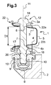
構造要素1は、所定の距離D1(図3)によって離間している、2つのほぼ平行な壁、第1の上側壁3及び第2の下側壁4を備える。この場合、これら上側壁3及び下側壁4は、ほぼ垂直の壁5によって接続されており、それによって、壁3、4、5が、ほぼ横向きのU字形である断面を形成する。例として、距離D1は45mmから60mmであってよい。
The structural element 1 comprises two substantially parallel walls, a first upper side wall 3 and a second lower side wall 4 separated by a predetermined distance D1 (FIG. 3). In this case, the upper side wall 3 and the lower side wall 4 are connected by a substantially
図5でより具体的に見えるとおり、上側壁3及び下側壁4は、それぞれ貫通孔6、7によって穿孔されている。これらの孔6、7は、互いに対向して位置している。言い換えれば、これらの軸は、一致する。
As seen more specifically in FIG. 5, the upper and lower side walls 3 and 4 are perforated by the through
機能要素2は、受容ハウジング10(図3)が設けられたエラストマーブロック9を受容しているハウジング8を備える。この配設によって、構造要素1と機能要素2との間の振動がフィルタリングされることが可能なる。しかし、本発明はこの配設に限定されず、受容ハウジングは、機能要素2内に直接製造されることができる。受容ハウジング10の軸11は、機能要素2の孔6、7の軸に一致する。図1から3に見えるように、機能要素2の受容ハウジング10は、構造要素1の第2の壁付近、前記壁の下方に位置している。例として、軸11の方向に、下側壁4を、具体的には、受容ハウジング10の構造要素1を、離間している距離D2は、4から10mmである。
The
本アセンブリは、構造要素1の孔6、7を貫通しているピン12によって実施されている。このピン12の一自由端13は、受容ハウジング10内に受容及び保持され、ピン12の別の自由端は、構造要素2の第1の壁3の外面上にもたれかかっている、拡張ヘッド14を有する。言い換えれば、ピン12のヘッド14は、第2の壁4に対向していない、第1の壁3の面上に載っている(図3)。
The assembly is implemented by means of a
ピン12は、構造要素1の孔6、7によって保持され固定されている。この目的のため、孔6、7は、ピン12を、具体的には垂直に(ピン12のシャフトの軸に平行に)及び横方向に(ピン12のシャフトに垂直に)、保持し締着するための手段を形成するように配設されている。下側壁4と上側壁3との離間D1によって、こうしてピン12は、屈曲または座屈のリスクが低減された状態で堅固に横方向に保持されている。
The
示される例では、保持し締着するための手段は、道具を使用せずにピン12を締着する「1/4回転」タイプとして配設されている。構造要素1の孔6、7とピン12とは、このように、ピン12を軸を中心にして1/4回転させることによって締着することができる形状をしている。しかし、本発明はこのタイプの締着に限定されず、例えばネジ接続といった、さらなるタイプの締着も想到可能である。「1/4回転」式締着を可能にする、孔6、7及びピン12の例示的実施形態は、以下で開示される。しかし、本発明はこの具体的実施形態に限定されず、「1/4回転」式締着を可能にする任意の他の形状の実施形態が、想到可能である。
In the example shown, the means for holding and fastening are arranged as a "quarter turn" type, which clamps the
したがって本例では、孔6、7のそれぞれが、図5から見えるように、丸い、わずかに拡張された中央部6a、7aを伴う、長方形の形状を有する。次いでピン12は、2つの対向する平行な平坦部15、16を備える、円筒形のシャフトを有する(図4)。各孔6、7の中央の丸い拡張部6a、7aは、ピン12の円筒形シャフトの直径と等しいかそれよりやや大きいが、孔6、7の長さよりは小さい直径を有する、円に相当する形状を有する。ピン12にはまた、直径方向に互いに対向し、同一平面上で、円筒形シャフトに対してほぼ垂直に延伸し、平坦部同士の間に配設されている、2つの止め具部17、18も設けられている。これらの止め具部17、18は、ピン12の平坦部15、16が長方形の孔6、7の長辺に対して平行になるようにピン12が配向されているときに、孔6、7を通過するように形作られている。こうして、ピン12を1/4回転させることによって、止め具部17、18が孔6、7の幅方向に下側壁4の下方に配置され、これによって、図3で見えるように、図の軸11に一致するピン12の軸に沿って、ピン12がブロックされることが理解される。
Thus, in this example, each of the
ピン12の締着は、2つの直径方向に対向する舌部19(そのうちの1つだけが図4で見えている)の製造によっても改善され得る。舌部19は、ヘッド14の下面に固定され、ピン12のシャフトに向けて配向され、ピン12の回転後、即ちピン12のアセンブル位置において、上側孔6の縁部と係合し得る。さらに、示される例では、壁3、4は孔6、7それぞれの周囲に孔6、7の軸11に対して垂直に延伸する、外表面部分3a、4bを有する。このように、ピン12の止め具部17、18は、下側外表面部4bをフラットに支持し、一方で舌部19は、ほぼ上側外表面部3aの領域で、孔6の縁を支持することができる。こうして、ピン12の軸に沿った保持状態は改善される。
The fastening of the
本例では、ピン12は、初期破壊ゾーン20をさらに備える。初期破壊ゾーン20は、この場合には狭隘部を形成する溝であり、図3に見えるように、止め具部17、18と、受容ハウジング10内に挿入されているピン12の自由端13の一部との間に配設されている。当初破壊部20はこのように、ピン12を保持するための2つのゾーン、即ち構造要素1の下側壁4の孔7及び機能要素2の受容ハウジング10から、近距離に配設されている。こうして、構造要素1の、車両の後部に向けたX方向へのピン12の軸を横断する移動を生じさせる衝撃によって、ピン12の初期破壊部20の領域における破壊が、必然的に発生する。
In this example, the
図面に関連して記載される実施形態では、構造要素1の壁3、4は、ポリマー材料製の装備品22によって部分的に覆われた、U字形の断面の金属外郭部の一部を形成する。具体的には、この装備品22は、それぞれの孔6、7の周囲で、上側壁3及び下側壁4の外表面を覆っている。示される例では、この装備品22は、外郭部の外表面全体にわたっては延伸していないが、孔6の周囲の上側装備品22a及び、孔7の周囲の下側装備品22bを備えている。これらの上側装備品22a及び下側装備品22bは、図3で最も具体的に見えるように、それぞれ上側壁3及び下側壁4の外表面上に、言い換えれば、互いに対向しない面上に、存在する。言い換えれば、これらの装備品22a及び22bは、壁3と壁4との間には延伸しない。この配置には、とりわけこの装備品22がオーバーモールドによって製造される場合には、複数の利点がある。具体的には、この場合、装備品22の製造のために鋳型要素の通過を可能にするように、金属外郭部の孔6及び7を特大サイズにする必要がない。なぜならば、前記装備品は金属外郭部の外側にあるからである。このように、孔6、7はまさに正しいサイズになる寸法であってよい。これによって、具体的には、孔の存在によって起こされる可能性がある、金属外郭部の脆化を制限することが可能になる。これらの利点は、ポリマー材料製の部品から製造される構造要素の場合にもまた、認められる。言い換えれば、その部品の外郭部及びその装備品は、ポリマー材料製の、全く同一の部品を形成する。
In the embodiment described in connection with the drawings, the walls 3, 4 of the structural element 1 form part of a U-shaped cross-section metal shell partly covered by
この場合、装備品22は金属外郭部上にオーバーモールドされており、それによって後続するアセンブリを伴わない、比較的簡潔な大量生産が可能になる。しかし装備品22の、他の手段、例えば接着やクリッピングやその他によるアセンブリを想到することも、また可能である。
In this case, the
さらに、金属外郭部の場合、外郭部の製造方法を簡素化するために、外郭部の壁3、4は、図に見えるように厳密に平行でなくてよい。この場合、外側装備品22によって、孔6、7の軸11に対して垂直に延伸し、本発明の意図の範囲内で保持及び締着する手段の一部を形成し得、ピン12を軸に沿ってブロックし保持するために好適な、外面部3a、4bの製造が可能になる。軸11に対して垂直に延伸する、こうした外面部3a、4bは、完全にポリマー材料製である構造要素を製造することによってもまた容易に得られてよいことは、留意されるであろう。
Furthermore, in the case of metal shell, in order to simplify the method of manufacturing the shell, the walls 3, 4 of the shell need not be exactly parallel as seen in the figure. In this case, the
例として、装備品または外郭部用に製造されることができるポリマー材料は、ポリプロピレン、おそらくは強化ポリプロピレン、または、所望の剛性を有する任意の他のポリマー材料であってよい。外郭部は、金属である場合、アルミニウム、アルミニウムベースの合金、または鋼、具体的にはステンレス鋼であってよい。 By way of example, the polymeric material that can be produced for fittings or shells can be polypropylene, perhaps reinforced polypropylene, or any other polymeric material having the desired stiffness. The shell, if metal, may be aluminum, an alloy based on aluminum, or steel, in particular stainless steel.
記載の例では、構造要素は、ほぼU字形の断面を有する外郭部の形態である。しかし、本発明は、このタイプの断面に限定されず、上記のようにピンを受容するために穿孔可能な、2つのほぼ平行な壁を有する限り、H字形またはI字形と同様の断面が想到可能である。 In the described example, the structural element is in the form of an outer shell having a substantially U-shaped cross section. However, the present invention is not limited to this type of cross-section, and a cross-section similar to an H-shape or I-shape is conceivable as long as it has two generally parallel walls that can be perforated to receive pins as described above. Is possible.
Claims (9)
− ほぼ平行で、所定の距離(D1)で離間し、前記構造要素(1)の一部を形成している第1の壁(3)及び第2の壁(4)であって、各壁(3、4)は貫通孔(6、7)によって穿孔されており、前記孔(6、7)は互いに対向している、第1の壁(3)及び第2の壁(4)、
− 前記機能要素(2)内に製造され、前記構造要素(1)の前記孔(6、7)と同じ軸を有し、前記構造要素(1)の前記第2の壁(4)の近傍に位置する受容ハウジング(10)、並びに
− 前記構造要素(1)の前記孔(6、7)を貫通するピン(12)であって、前記ピン(12)の自由端(13)は、前記受容ハウジング(10)内に受容及び保持され、前記ピン(12)の別の端部は、前記構造要素(1)の前記第1の壁(3)の外表面に当接する拡張ヘッド(14)を有するピンを備える、アセンブリ。 An assembly of a structural element (1) of a motor vehicle and a functional element (2),
A first wall (3) and a second wall (4) substantially parallel, spaced apart by a predetermined distance (D1) and forming part of said structural element (1), each wall (3, 4) are perforated by through holes (6, 7), said holes (6, 7) facing each other, a first wall (3) and a second wall (4),
-Manufactured in said functional element (2) and having the same axis as said holes (6, 7) of said structural element (1), in the vicinity of said second wall (4) of said structural element (1) A receiving housing (10), and a pin (12) passing through the holes (6, 7) of the structural element (1), the free end (13) of the pin (12) being receiving housing (10) receiving and retained within, another end portion of the pin (12), said first wall (3) extended head you contact the outer surface of the structural element (1) ( comprising a pin which have a 14), the assembly.
Applications Claiming Priority (3)
| Application Number | Priority Date | Filing Date | Title |
|---|---|---|---|
| FR1455497A FR3022211B1 (en) | 2014-06-16 | 2014-06-16 | ASSEMBLY OF A MOTOR VEHICLE STRUCTURE ELEMENT AND A FUNCTIONAL ELEMENT |
| FR1455497 | 2014-06-16 | ||
| PCT/FR2015/051573 WO2015193596A1 (en) | 2014-06-16 | 2015-06-15 | Assembly of a structural element of a motor vehicle and a functional element |
Publications (2)
| Publication Number | Publication Date |
|---|---|
| JP2017526567A JP2017526567A (en) | 2017-09-14 |
| JP6552527B2 true JP6552527B2 (en) | 2019-07-31 |
Family
ID=51518983
Family Applications (1)
| Application Number | Title | Priority Date | Filing Date |
|---|---|---|---|
| JP2016572446A Active JP6552527B2 (en) | 2014-06-16 | 2015-06-15 | Assembly of automotive structural and functional elements |
Country Status (8)
| Country | Link |
|---|---|
| EP (1) | EP3154843B1 (en) |
| JP (1) | JP6552527B2 (en) |
| KR (1) | KR102363827B1 (en) |
| CN (1) | CN106660592B (en) |
| BR (1) | BR112016029458B1 (en) |
| FR (1) | FR3022211B1 (en) |
| RU (1) | RU2694400C2 (en) |
| WO (1) | WO2015193596A1 (en) |
Families Citing this family (4)
| Publication number | Priority date | Publication date | Assignee | Title |
|---|---|---|---|---|
| FR3049258B1 (en) * | 2016-03-24 | 2019-05-03 | Valeo Systemes Thermiques | ATTACHING AN AIR INTAKE AIR AIR SYSTEM FOR A FRONT OF A VEHICLE |
| FR3055695B1 (en) * | 2016-09-07 | 2018-08-31 | Sumiriko Sd France S.A.S. | ASSEMBLY FOR THE SUPPORT WITH FILTERING OF VIBRATION OF A FUNCTIONAL ELEMENT ON A STRUCTURAL ELEMENT OF THE BODY OF A GEAR AND RELATED FUNCTIONAL ELEMENT |
| CN111741863A (en) * | 2018-01-19 | 2020-10-02 | 法雷奥热系统公司 | Shutter control device, in particular for a motor vehicle, and frame comprising such a device |
| PL238549B1 (en) * | 2018-06-28 | 2021-09-06 | Mb Pneumatyka Spolka Z Ograniczona Odpowiedzialnoscia | Block of air distributor in pneumatic systems of commercial vehicles |
Family Cites Families (17)
| Publication number | Priority date | Publication date | Assignee | Title |
|---|---|---|---|---|
| SU846325A1 (en) * | 1979-01-29 | 1981-07-15 | Предприятие П/Я М-5572 | Actuator of vehicle radiator blind |
| JPS60100219U (en) * | 1983-12-16 | 1985-07-08 | トヨタ自動車株式会社 | Radiator support device |
| SU1379140A1 (en) * | 1986-09-04 | 1988-03-07 | Кременчугский автомобильный завод им.50-летия Советской Украины | Arrangement for securing radiator on vehicle framework |
| DE3926568C1 (en) * | 1989-08-11 | 1990-09-27 | Mercedes-Benz Aktiengesellschaft, 7000 Stuttgart, De | |
| KR19980062769A (en) * | 1996-12-30 | 1998-10-07 | 김영귀 | Cross member of car |
| JP4461563B2 (en) * | 1999-10-20 | 2010-05-12 | 株式会社デンソー | Vehicle front-end structure |
| JP2005035435A (en) * | 2003-07-16 | 2005-02-10 | Calsonic Kansei Corp | Body front part structure of automobile |
| FR2864005B1 (en) * | 2003-12-22 | 2007-04-20 | Faurecia Bloc Avant | STRUCTURAL ELEMENT FOR A MOTOR VEHICLE COMPRISING TWO METALLIC BODIES AND A PLASTIC REINFORCING PART PROVIDING BODY LINKING, AND CORRESPONDING MOTOR VEHICLE |
| KR20050081254A (en) * | 2004-02-13 | 2005-08-18 | 한라공조주식회사 | A radiator mounting structure of a front end module for a vehicle |
| FR2866306B1 (en) * | 2004-02-17 | 2006-05-26 | Valeo Thermique Moteur Sa | METAL COMPOSITE STRUCTURE AND PLASTIC MATERIAL, ESPECIALLY FOR A FRONT PANEL OF A MOTOR VEHICLE. |
| JP4292171B2 (en) * | 2005-05-23 | 2009-07-08 | 本田技研工業株式会社 | Front body structure of automobile |
| US7347489B2 (en) * | 2005-09-13 | 2008-03-25 | Chrysler Llc | Front end for a vehicle and method for making same |
| CA2623225C (en) * | 2005-09-30 | 2013-11-12 | Magna International Inc. | Locator assembly |
| FR2911573B1 (en) * | 2007-01-19 | 2009-04-24 | Faurecia Bloc Avant | FRONT PANEL OF MOTOR VEHICLE |
| DE102007018461B4 (en) * | 2007-04-19 | 2017-10-19 | Robert Bosch Gmbh | Windscreen wiper system drive attached to a support tube |
| FR2948902B1 (en) * | 2009-08-05 | 2011-11-18 | Peugeot Citroen Automobiles Sa | DEVICE FOR FASTENING A COOLING ASSEMBLY ON THE FRONT PANEL OF A VEHICLE |
| RU123373U1 (en) * | 2012-06-26 | 2012-12-27 | Открытое акционерное общество "Ульяновский автомобильный завод" | RADIATOR SUSPENSION |
-
2014
- 2014-06-16 FR FR1455497A patent/FR3022211B1/en not_active Expired - Fee Related
-
2015
- 2015-06-15 EP EP15733831.0A patent/EP3154843B1/en active Active
- 2015-06-15 BR BR112016029458-0A patent/BR112016029458B1/en active IP Right Grant
- 2015-06-15 KR KR1020177001243A patent/KR102363827B1/en active IP Right Grant
- 2015-06-15 RU RU2017101022A patent/RU2694400C2/en active
- 2015-06-15 CN CN201580039035.9A patent/CN106660592B/en active Active
- 2015-06-15 JP JP2016572446A patent/JP6552527B2/en active Active
- 2015-06-15 WO PCT/FR2015/051573 patent/WO2015193596A1/en active Application Filing
Also Published As
| Publication number | Publication date |
|---|---|
| KR102363827B1 (en) | 2022-02-16 |
| EP3154843B1 (en) | 2018-08-15 |
| BR112016029458A2 (en) | 2017-08-22 |
| FR3022211A1 (en) | 2015-12-18 |
| CN106660592B (en) | 2018-10-12 |
| FR3022211B1 (en) | 2016-05-27 |
| RU2017101022A (en) | 2018-07-16 |
| BR112016029458B1 (en) | 2022-11-01 |
| RU2017101022A3 (en) | 2018-12-13 |
| KR20170018943A (en) | 2017-02-20 |
| EP3154843A1 (en) | 2017-04-19 |
| CN106660592A (en) | 2017-05-10 |
| JP2017526567A (en) | 2017-09-14 |
| WO2015193596A1 (en) | 2015-12-23 |
| RU2694400C2 (en) | 2019-07-12 |
Similar Documents
| Publication | Publication Date | Title |
|---|---|---|
| JP6552527B2 (en) | Assembly of automotive structural and functional elements | |
| KR101428276B1 (en) | Battery tray for vehicle | |
| US9926828B2 (en) | Tailpipe cover for an exhaust system of a motor vehicle and exhaust system having such a tailpipe cover | |
| JP2019089484A (en) | Vehicle impact absorption member | |
| JP2011093409A (en) | Structure of mounting accessory of fuel tank | |
| JP5044666B2 (en) | Mudguard mounting structure | |
| US9738241B2 (en) | Bumper absorber attachment structure | |
| US9453594B2 (en) | Fixing device | |
| JP5772440B2 (en) | Battery mounting structure | |
| US11358530B2 (en) | Apparatus for receiving an object in a motor vehicle | |
| US9539872B2 (en) | Mounting unit of shock absorber for vehicle | |
| EP3124844A1 (en) | Clip for securing an elongated article | |
| KR101073951B1 (en) | Mounting method for towing hook pipe nut in vehicle | |
| WO2017135407A1 (en) | Vehicle interior component | |
| EP2916017B1 (en) | Noise reduction baffle and method for installing same | |
| JP6555476B2 (en) | Vehicle front structure | |
| JP6394538B2 (en) | Nut mounting structure | |
| EP3800091B1 (en) | Number plate holder | |
| JP6068201B2 (en) | Clamp and component support system | |
| JP2013007433A (en) | Fastening seat-face pitch absorption bracket and reinforcing member | |
| JP6332351B2 (en) | Anti-vibration device for automobile and anti-vibration structure for automobile | |
| KR101275139B1 (en) | Member for fixing the parts for industry of and structure for fixing | |
| JP6885316B2 (en) | Retention structure for mounted parts on the floor panel | |
| KR101593413B1 (en) | Clip fixing structure for mount bumper beam of car | |
| KR102428225B1 (en) | A stay for bumper beam |
Legal Events
| Date | Code | Title | Description |
|---|---|---|---|
| A621 | Written request for application examination |
Free format text: JAPANESE INTERMEDIATE CODE: A621 Effective date: 20180405 |
|
| A977 | Report on retrieval |
Free format text: JAPANESE INTERMEDIATE CODE: A971007 Effective date: 20190214 |
|
| A131 | Notification of reasons for refusal |
Free format text: JAPANESE INTERMEDIATE CODE: A131 Effective date: 20190219 |
|
| A521 | Request for written amendment filed |
Free format text: JAPANESE INTERMEDIATE CODE: A523 Effective date: 20190516 |
|
| TRDD | Decision of grant or rejection written | ||
| A01 | Written decision to grant a patent or to grant a registration (utility model) |
Free format text: JAPANESE INTERMEDIATE CODE: A01 Effective date: 20190604 |
|
| A61 | First payment of annual fees (during grant procedure) |
Free format text: JAPANESE INTERMEDIATE CODE: A61 Effective date: 20190702 |
|
| R150 | Certificate of patent or registration of utility model |
Ref document number: 6552527 Country of ref document: JP Free format text: JAPANESE INTERMEDIATE CODE: R150 |
|
| R250 | Receipt of annual fees |
Free format text: JAPANESE INTERMEDIATE CODE: R250 |
|
| R250 | Receipt of annual fees |
Free format text: JAPANESE INTERMEDIATE CODE: R250 |