JP6549717B2 - Stent - Google Patents
Stent Download PDFInfo
- Publication number
- JP6549717B2 JP6549717B2 JP2017536957A JP2017536957A JP6549717B2 JP 6549717 B2 JP6549717 B2 JP 6549717B2 JP 2017536957 A JP2017536957 A JP 2017536957A JP 2017536957 A JP2017536957 A JP 2017536957A JP 6549717 B2 JP6549717 B2 JP 6549717B2
- Authority
- JP
- Japan
- Prior art keywords
- stent
- wire
- coil
- porosity
- wires
- Prior art date
- Legal status (The legal status is an assumption and is not a legal conclusion. Google has not performed a legal analysis and makes no representation as to the accuracy of the status listed.)
- Active
Links
Images


Classifications
-
- A—HUMAN NECESSITIES
- A61—MEDICAL OR VETERINARY SCIENCE; HYGIENE
- A61F—FILTERS IMPLANTABLE INTO BLOOD VESSELS; PROSTHESES; DEVICES PROVIDING PATENCY TO, OR PREVENTING COLLAPSING OF, TUBULAR STRUCTURES OF THE BODY, e.g. STENTS; ORTHOPAEDIC, NURSING OR CONTRACEPTIVE DEVICES; FOMENTATION; TREATMENT OR PROTECTION OF EYES OR EARS; BANDAGES, DRESSINGS OR ABSORBENT PADS; FIRST-AID KITS
- A61F2/00—Filters implantable into blood vessels; Prostheses, i.e. artificial substitutes or replacements for parts of the body; Appliances for connecting them with the body; Devices providing patency to, or preventing collapsing of, tubular structures of the body, e.g. stents
- A61F2/82—Devices providing patency to, or preventing collapsing of, tubular structures of the body, e.g. stents
- A61F2/86—Stents in a form characterised by the wire-like elements; Stents in the form characterised by a net-like or mesh-like structure
- A61F2/88—Stents in a form characterised by the wire-like elements; Stents in the form characterised by a net-like or mesh-like structure the wire-like elements formed as helical or spiral coils
- A61F2/885—Stents in a form characterised by the wire-like elements; Stents in the form characterised by a net-like or mesh-like structure the wire-like elements formed as helical or spiral coils comprising a coil including a plurality of spiral or helical sections with alternate directions around a central axis
-
- A—HUMAN NECESSITIES
- A61—MEDICAL OR VETERINARY SCIENCE; HYGIENE
- A61F—FILTERS IMPLANTABLE INTO BLOOD VESSELS; PROSTHESES; DEVICES PROVIDING PATENCY TO, OR PREVENTING COLLAPSING OF, TUBULAR STRUCTURES OF THE BODY, e.g. STENTS; ORTHOPAEDIC, NURSING OR CONTRACEPTIVE DEVICES; FOMENTATION; TREATMENT OR PROTECTION OF EYES OR EARS; BANDAGES, DRESSINGS OR ABSORBENT PADS; FIRST-AID KITS
- A61F2/00—Filters implantable into blood vessels; Prostheses, i.e. artificial substitutes or replacements for parts of the body; Appliances for connecting them with the body; Devices providing patency to, or preventing collapsing of, tubular structures of the body, e.g. stents
- A61F2/82—Devices providing patency to, or preventing collapsing of, tubular structures of the body, e.g. stents
- A61F2/86—Stents in a form characterised by the wire-like elements; Stents in the form characterised by a net-like or mesh-like structure
- A61F2/90—Stents in a form characterised by the wire-like elements; Stents in the form characterised by a net-like or mesh-like structure characterised by a net-like or mesh-like structure
-
- A—HUMAN NECESSITIES
- A61—MEDICAL OR VETERINARY SCIENCE; HYGIENE
- A61F—FILTERS IMPLANTABLE INTO BLOOD VESSELS; PROSTHESES; DEVICES PROVIDING PATENCY TO, OR PREVENTING COLLAPSING OF, TUBULAR STRUCTURES OF THE BODY, e.g. STENTS; ORTHOPAEDIC, NURSING OR CONTRACEPTIVE DEVICES; FOMENTATION; TREATMENT OR PROTECTION OF EYES OR EARS; BANDAGES, DRESSINGS OR ABSORBENT PADS; FIRST-AID KITS
- A61F2/00—Filters implantable into blood vessels; Prostheses, i.e. artificial substitutes or replacements for parts of the body; Appliances for connecting them with the body; Devices providing patency to, or preventing collapsing of, tubular structures of the body, e.g. stents
- A61F2/82—Devices providing patency to, or preventing collapsing of, tubular structures of the body, e.g. stents
- A61F2/852—Two or more distinct overlapping stents
-
- A—HUMAN NECESSITIES
- A61—MEDICAL OR VETERINARY SCIENCE; HYGIENE
- A61F—FILTERS IMPLANTABLE INTO BLOOD VESSELS; PROSTHESES; DEVICES PROVIDING PATENCY TO, OR PREVENTING COLLAPSING OF, TUBULAR STRUCTURES OF THE BODY, e.g. STENTS; ORTHOPAEDIC, NURSING OR CONTRACEPTIVE DEVICES; FOMENTATION; TREATMENT OR PROTECTION OF EYES OR EARS; BANDAGES, DRESSINGS OR ABSORBENT PADS; FIRST-AID KITS
- A61F2/00—Filters implantable into blood vessels; Prostheses, i.e. artificial substitutes or replacements for parts of the body; Appliances for connecting them with the body; Devices providing patency to, or preventing collapsing of, tubular structures of the body, e.g. stents
- A61F2/82—Devices providing patency to, or preventing collapsing of, tubular structures of the body, e.g. stents
- A61F2/86—Stents in a form characterised by the wire-like elements; Stents in the form characterised by a net-like or mesh-like structure
- A61F2/88—Stents in a form characterised by the wire-like elements; Stents in the form characterised by a net-like or mesh-like structure the wire-like elements formed as helical or spiral coils
-
- A—HUMAN NECESSITIES
- A61—MEDICAL OR VETERINARY SCIENCE; HYGIENE
- A61F—FILTERS IMPLANTABLE INTO BLOOD VESSELS; PROSTHESES; DEVICES PROVIDING PATENCY TO, OR PREVENTING COLLAPSING OF, TUBULAR STRUCTURES OF THE BODY, e.g. STENTS; ORTHOPAEDIC, NURSING OR CONTRACEPTIVE DEVICES; FOMENTATION; TREATMENT OR PROTECTION OF EYES OR EARS; BANDAGES, DRESSINGS OR ABSORBENT PADS; FIRST-AID KITS
- A61F2/00—Filters implantable into blood vessels; Prostheses, i.e. artificial substitutes or replacements for parts of the body; Appliances for connecting them with the body; Devices providing patency to, or preventing collapsing of, tubular structures of the body, e.g. stents
- A61F2/95—Instruments specially adapted for placement or removal of stents or stent-grafts
- A61F2/954—Instruments specially adapted for placement or removal of stents or stent-grafts for placing stents or stent-grafts in a bifurcation
-
- A—HUMAN NECESSITIES
- A61—MEDICAL OR VETERINARY SCIENCE; HYGIENE
- A61F—FILTERS IMPLANTABLE INTO BLOOD VESSELS; PROSTHESES; DEVICES PROVIDING PATENCY TO, OR PREVENTING COLLAPSING OF, TUBULAR STRUCTURES OF THE BODY, e.g. STENTS; ORTHOPAEDIC, NURSING OR CONTRACEPTIVE DEVICES; FOMENTATION; TREATMENT OR PROTECTION OF EYES OR EARS; BANDAGES, DRESSINGS OR ABSORBENT PADS; FIRST-AID KITS
- A61F2/00—Filters implantable into blood vessels; Prostheses, i.e. artificial substitutes or replacements for parts of the body; Appliances for connecting them with the body; Devices providing patency to, or preventing collapsing of, tubular structures of the body, e.g. stents
- A61F2/82—Devices providing patency to, or preventing collapsing of, tubular structures of the body, e.g. stents
- A61F2002/823—Stents, different from stent-grafts, adapted to cover an aneurysm
-
- A—HUMAN NECESSITIES
- A61—MEDICAL OR VETERINARY SCIENCE; HYGIENE
- A61F—FILTERS IMPLANTABLE INTO BLOOD VESSELS; PROSTHESES; DEVICES PROVIDING PATENCY TO, OR PREVENTING COLLAPSING OF, TUBULAR STRUCTURES OF THE BODY, e.g. STENTS; ORTHOPAEDIC, NURSING OR CONTRACEPTIVE DEVICES; FOMENTATION; TREATMENT OR PROTECTION OF EYES OR EARS; BANDAGES, DRESSINGS OR ABSORBENT PADS; FIRST-AID KITS
- A61F2220/00—Fixations or connections for prostheses classified in groups A61F2/00 - A61F2/26 or A61F2/82 or A61F9/00 or A61F11/00 or subgroups thereof
- A61F2220/0025—Connections or couplings between prosthetic parts, e.g. between modular parts; Connecting elements
- A61F2220/0075—Connections or couplings between prosthetic parts, e.g. between modular parts; Connecting elements sutured, ligatured or stitched, retained or tied with a rope, string, thread, wire or cable
-
- A—HUMAN NECESSITIES
- A61—MEDICAL OR VETERINARY SCIENCE; HYGIENE
- A61F—FILTERS IMPLANTABLE INTO BLOOD VESSELS; PROSTHESES; DEVICES PROVIDING PATENCY TO, OR PREVENTING COLLAPSING OF, TUBULAR STRUCTURES OF THE BODY, e.g. STENTS; ORTHOPAEDIC, NURSING OR CONTRACEPTIVE DEVICES; FOMENTATION; TREATMENT OR PROTECTION OF EYES OR EARS; BANDAGES, DRESSINGS OR ABSORBENT PADS; FIRST-AID KITS
- A61F2250/00—Special features of prostheses classified in groups A61F2/00 - A61F2/26 or A61F2/82 or A61F9/00 or A61F11/00 or subgroups thereof
- A61F2250/0014—Special features of prostheses classified in groups A61F2/00 - A61F2/26 or A61F2/82 or A61F9/00 or A61F11/00 or subgroups thereof having different values of a given property or geometrical feature, e.g. mechanical property or material property, at different locations within the same prosthesis
- A61F2250/0023—Special features of prostheses classified in groups A61F2/00 - A61F2/26 or A61F2/82 or A61F9/00 or A61F11/00 or subgroups thereof having different values of a given property or geometrical feature, e.g. mechanical property or material property, at different locations within the same prosthesis differing in porosity
-
- A—HUMAN NECESSITIES
- A61—MEDICAL OR VETERINARY SCIENCE; HYGIENE
- A61F—FILTERS IMPLANTABLE INTO BLOOD VESSELS; PROSTHESES; DEVICES PROVIDING PATENCY TO, OR PREVENTING COLLAPSING OF, TUBULAR STRUCTURES OF THE BODY, e.g. STENTS; ORTHOPAEDIC, NURSING OR CONTRACEPTIVE DEVICES; FOMENTATION; TREATMENT OR PROTECTION OF EYES OR EARS; BANDAGES, DRESSINGS OR ABSORBENT PADS; FIRST-AID KITS
- A61F2250/00—Special features of prostheses classified in groups A61F2/00 - A61F2/26 or A61F2/82 or A61F9/00 or A61F11/00 or subgroups thereof
- A61F2250/0014—Special features of prostheses classified in groups A61F2/00 - A61F2/26 or A61F2/82 or A61F9/00 or A61F11/00 or subgroups thereof having different values of a given property or geometrical feature, e.g. mechanical property or material property, at different locations within the same prosthesis
- A61F2250/0036—Special features of prostheses classified in groups A61F2/00 - A61F2/26 or A61F2/82 or A61F9/00 or A61F11/00 or subgroups thereof having different values of a given property or geometrical feature, e.g. mechanical property or material property, at different locations within the same prosthesis differing in thickness
-
- A—HUMAN NECESSITIES
- A61—MEDICAL OR VETERINARY SCIENCE; HYGIENE
- A61F—FILTERS IMPLANTABLE INTO BLOOD VESSELS; PROSTHESES; DEVICES PROVIDING PATENCY TO, OR PREVENTING COLLAPSING OF, TUBULAR STRUCTURES OF THE BODY, e.g. STENTS; ORTHOPAEDIC, NURSING OR CONTRACEPTIVE DEVICES; FOMENTATION; TREATMENT OR PROTECTION OF EYES OR EARS; BANDAGES, DRESSINGS OR ABSORBENT PADS; FIRST-AID KITS
- A61F2250/00—Special features of prostheses classified in groups A61F2/00 - A61F2/26 or A61F2/82 or A61F9/00 or A61F11/00 or subgroups thereof
- A61F2250/0058—Additional features; Implant or prostheses properties not otherwise provided for
- A61F2250/006—Additional features; Implant or prostheses properties not otherwise provided for modular
Description
本出願は、参照によりそのまま本書に組み込まれる、2015年1月12日にStent Designsという名称で出願された米国仮特許出願第62/102,483号および2015年1月28日にStent Insertという名称で出願された米国仮特許出願第62/108,699号について優先権を主張する。 This application claims the benefit of US Provisional Patent Application Ser. No. 62 / 102,483, filed on Jan. 12, 2015 under the name Stent Designs, and entitled Stent Insert on Jan. 28, 2015, which are hereby incorporated by reference in their entirety. Priority is claimed to US Provisional Patent Application No. 62 / 108,699 filed in
ステントは、狭窄がある場所での分流や血流の復元など、脈管系内で様々な理由で使用されている。以下の詳細説明は、血管枝の分岐部動脈瘤の治療など、様々な状況に使用可能なステントデザイン、編組ステントの径方向強度を増大させるステントデザイン、空隙率の異なる領域を有するステント、およびステントを連結する方法に関する。 Stents are used in the vasculature for a variety of reasons, such as diversion or restoration of blood flow where a stenosis is present. The following detailed description describes a stent design that can be used in a variety of situations, such as treatment of bifurcation aneurysms of a blood vessel branch, a stent design that increases the radial strength of a braided stent, a stent having regions of differing porosity, and a stent On how to connect
以下の出願のすべて、すなわち、2010年12月13日にStentという名称で出願された米国仮特許出願第61/422,604号明細書、2010年12月20日にPolymer Stent And Method Of Manufactureという名称で出願された米国仮特許出願第61/425,175号明細書、国際出願日2010年12月21日の、Stentという名称の国際特許出願第PCT/US2010/061627号明細書、2010年12月28日にPolymer Stent And Method Of Manufacture 2という名称で出願された米国仮特許出願第61/427,773号明細書、および2011年1月7日にStentという名称で出願された米国非仮特許出願第13/003,277号明細書が参照によりそのまま本書に組み込まれる。 All of the following applications: U.S. Provisional Patent Application No. 61 / 422,604, filed Dec. 13, 2010 under the name Stent, named Dec. 20, 2010, Polymer Stent And Method Of Manufacture. US Provisional Patent Application No. 61 / 425,175 filed under the name, International Patent Application No. PCT / US2010 / 061627, named Stent, Dec. 21, 2010, 12 Dec. 2010 US Provisional Patent Application No. 61 / 427,773, filed on Jan. 28, under the name Polymer Stent And Method Of Manufacture 2, and US Non-Protemporal Patents filed on Jan. 7, 2011, under the name Stent Application No. 13 / No. 003,277 is incorporated herein by reference in its entirety.
本発明は、血管動脈瘤の塞栓術などの体腔の治療用の装置と、そのような装置を製造及び使用する方法に関する。 The present invention relates to devices for treatment of body cavities, such as embolization of vascular aneurysms, and methods of making and using such devices.
多くの臨床的状況で体腔、血管および他の内腔の塞栓術による閉塞が望まれている。例えば、不妊手術を目的とした卵管の閉塞、卵円孔開存、動脈管開存、左心耳、心房中隔欠損などの心臓欠陥の閉塞性修復。そのような状況での閉塞装置の機能は、患者の治療的有用性のために体腔、内腔、血管、間隙、欠損への、またはそれらを通る体液の流れを実質的に遮断または抑制することである。 Embolic occlusion of body cavities, blood vessels and other lumens is desired in many clinical situations. For example, obstructive repair of heart defects such as occlusion of the fallopian tube, patent foramen ovale, patellar artery, left atrial appendage, atrial septal defect for the purpose of sterilization. The function of the occlusion device in such a situation is to substantially block or inhibit the flow of fluid into, through, or through body cavities, lumens, blood vessels, gaps, defects for therapeutic utility of the patient. It is.
血管の塞栓術は多くの血管異常を修復することも望まれている。例えば、血管塞栓術は、血管からの出血を抑制するため、腫瘍への血液供給を遮断するため、血管動脈瘤、特に頭蓋内動脈瘤を閉塞するために使用されている。 Embolization of blood vessels is also desired to repair many vascular abnormalities. For example, vascular embolization is used to occlude vascular aneurysms, in particular intracranial aneurysms, to inhibit bleeding from blood vessels and to block the blood supply to the tumor.
近年、動脈瘤治療のための血管塞栓術が大きな注目を集めている。いくつかの異なる治療法が従来技術で示されている。有望な1つの方法は、血栓形成マイクロコイルの使用である。このようなマイクロコイルは、生体親和性合金(典型的にはプラチナ、タングステンなどの放射線不透過材料)または適切なポリマーからなる場合がある。マイクロコイルの例は以下の特許、すなわち、米国特許第4,994,069号明細書−Ritchart他、米国特許第5,133,731号明細書−Butler他、米国特許第5,226,911号明細書−Chee他、米国特許第5,312,415号明細書−Palermo、米国特許第5,382,259号明細書−Phelps他、米国特許第5,382,260号明細書−Dormandy,Jr.他、米国特許第5,476,472号明細書−Dormandy,Jr.他、米国特許第5,578,074号明細書−Mirigian、米国特許第5,582,619号明細書−Ken、米国特許第5,624,461号明細書−Mariant、米国特許第5,645,558号明細書−Horton、米国特許第5,658,308号明細書−Snyder、および米国特許第5,718,711号明細書−Berenstein他、に開示されており、これら明細書のすべては参照により本書に組み込まれる。 In recent years, blood vessel embolization for the treatment of aneurysms has received great attention. Several different treatments are indicated in the prior art. One promising method is the use of thrombogenic microcoils. Such microcoils may be comprised of a biocompatible alloy (typically a radiopaque material such as platinum, tungsten, etc.) or a suitable polymer. Examples of microcoils are the following patents: U.S. Pat. No. 4,994,069-Ritchart et al., U.S. Pat. No. 5,133,731-Butler et al., U.S. Pat. No. 5,226,911 Specification-Chee et al., U.S. Pat. No. 5,312,415-Palermo, U.S. Pat. No. 5,382,259-Phelps et al., U.S. Pat. No. 5,382,260-Dormandy, Jr. . U.S. Pat. No. 5,476,472-Dormandy, Jr. et al. U.S. Pat. No. 5,578,074-Mirigian, U.S. Pat. No. 5,582,619-Ken, U.S. Pat. No. 5,624,461-Mariant, U.S. Pat. No. 5,645 , 558-Horton, U.S. Pat. No. 5,658,308-Snyder, and U.S. Pat. No. 5,718,711-Berenstein et al., All of which are incorporated herein by reference. Incorporated herein by reference.
近年、ステントも動脈瘤を治療するために使用されている。例えば、その内容が参照により組み込まれる米国特許第5,951,599号明細書−McCroryおよび米国特許出願公開第2002/0169473号明細書−Sepetka他に見られるように、マイクロコイルまたは他の塞栓用材料が動脈瘤内に進入させられるのに対して、ステントは動脈瘤周りの血管壁を補強するために使用することができる。米国特許出願公開第2006/0206201号明細書−Garcia他に見られ、参照により同じく組み込まれる別の例では、動脈瘤の内部を通る血流を減少させて最終的に血栓形成をもたらす、密に編まれたステントが動脈瘤の口を覆って留置される。 Recently, stents have also been used to treat aneurysms. For example, for microcoils or other embolizations as found in US Pat. No. 5,951,599-McCrory and US Patent Application Publication No. 2002/0169473-Sepetka et al., The contents of which are incorporated by reference. While the material is advanced into the aneurysm, a stent can be used to reinforce the vessel wall around the aneurysm. U.S. Patent Application Publication No. 2006/0206201-Another example, also found in Garcia et al., Also incorporated by reference, is to reduce blood flow through the interior of the aneurysm, resulting in thrombus formation ultimately, A braided stent is placed over the aneurysmal port.
分流と閉塞に加えて、本発明は、高被覆率または低空隙率が望ましい用途にも使用することができる。例えば、ステントで頸動脈狭窄を治療する際、ステント展開時または展開後の拡張時に、塞栓または微粒子が遊離するおそれがある。このような塞栓が脳内につかえて脳卒中を引き起こす可能性があるので、微粒子を捕捉するために低空隙率のステントを提供することが望ましい。高被覆率ステントのもう1つの用途は、冠動脈バイパス移植組織(伏在静脈移植組織またはSVGとも呼ばれる)や下肢の動脈および静脈など、血栓形成に陥りやすい身体の領域にある。血栓が遊離して組織の下流を閉塞する可能性があるので、本発明の高被覆率の装置を展開し、血栓を被覆および/または捕捉して血栓が移動するのを防止することが望ましい。 In addition to diversion and occlusion, the present invention can also be used in applications where high coverage or low porosity is desired. For example, when treating a carotid artery stenosis with a stent, there may be liberation of emboli or microparticles during stent deployment or expansion after deployment. It is desirable to provide a low porosity stent to capture particulates, as such emboli can lodge in the brain and cause a stroke. Another application of high coverage stents is in areas of the body susceptible to thrombus formation, such as coronary artery bypass graft tissue (also called saphenous vein graft tissue or SVG) and arteries and veins in the lower extremities. It is desirable to deploy the high coverage device of the present invention to coat and / or capture the thrombus to prevent it from migrating, as the thrombus may be released and occlude the downstream of the tissue.
一実施形態では、少なくとも1つのより低空隙率の領域と少なくとも1つのより高空隙率の領域とを有するステントが記載されている。 In one embodiment, a stent having at least one lower porosity area and at least one higher porosity area is described.
別の実施形態では、少なくとも1つのより低空隙率の領域と少なくとも1つのより高空隙率の領域とを有するステントが、空隙率が異なる隣接する複数のステントからなる。 In another embodiment, a stent having at least one lower porosity area and at least one higher porosity area comprises a plurality of adjacent stents having different porosity.
別の実施形態では、少なくとも1つのより低空隙率の領域と少なくとも1つのより高空隙率の領域とを有するステントが、分岐部動脈瘤を治療するために使用される。 In another embodiment, a stent having at least one lower porosity area and at least one higher porosity area is used to treat bifurcation aneurysms.
別の実施形態では、少なくとも1つの高空隙率領域を有するステントが、分岐部動脈瘤を治療するために当該高空隙率領域を抜けて別のステントを導入するために使用される。 In another embodiment, a stent having at least one high porosity area is used to introduce another stent through the high porosity area to treat bifurcation aneurysms.
別の実施形態では、編組ステントが、ステント強度を増大させるように選択的に厚くされた領域を利用する。 In another embodiment, a braided stent utilizes areas that are selectively thickened to increase stent strength.
別の実施形態では、複数のステントが連結されて1つのステントを作ってもよい。 In another embodiment, multiple stents may be linked to make one stent.
別の実施形態では、空隙率の異なるステントが連結されて空隙率の異なる領域を有する1つのステントを作ってもよい。 In another embodiment, stents of different porosity may be linked to make one stent with regions of different porosity.
別の実施形態では、編組ステントのワイヤ端が溶接されている。 In another embodiment, the wire ends of the braided stent are welded.
別の実施形態では、編組ステントが、視覚化を助けるようにステントを通じて螺旋状に巻かれたワイヤを有する。 In another embodiment, a braided stent has a wire helically wound through the stent to aid in visualization.
一実施形態では、ステントとともに使用可能なインサートが記載されている。 In one embodiment, an insert is described that can be used with a stent.
別の実施形態では、インサートを利用した単層ステントが記載されている。 In another embodiment, a single layer stent utilizing an insert is described.
別の実施形態では、インサートを利用した二層ステントが記載されている。 In another embodiment, a dual layer stent utilizing an insert is described.
別の実施形態では、インサートを利用した多層ステントが記載されている。 In another embodiment, a multilayer stent utilizing an insert is described.
別の実施形態では、ステントとともに使用可能な薬剤溶出性インサートが記載されている。 In another embodiment, a drug eluting insert is described which can be used with a stent.
別の実施形態では、薬剤溶出性インサートを利用した単層ステントが記載されている。 In another embodiment, a single layer stent utilizing a drug eluting insert is described.
別の実施形態では、薬剤溶出性インサートを利用した二層ステントが記載されている。 In another embodiment, a dual layer stent utilizing a drug eluting insert is described.
別の実施形態では、薬剤溶出性インサートを利用した多層ステントが記載されている。 In another embodiment, a multi-layer stent utilizing a drug eluting insert is described.
別の実施形態は、少なくとも1本の編まれたワイヤから形成された管形状であって,第1の空隙率を有するように編まれた第1の領域と、第1の空隙率より高い第2の空隙率を有するように編まれた第2の領域とを有する管形状を対象とする。 Another embodiment is a tubular shape formed from at least one braided wire, the first region braided to have a first porosity, and the first region being higher than the first porosity A tubular shape having a second region knitted to have a porosity of 2 is targeted.
別の実施形態は、第1の領域が第1の編組みパターンで編まれ、第2の領域が第2の編組みパターンで編まれている、上述のステントを対象とする。 Another embodiment is directed to the above-described stent, wherein the first region is braided in a first braided pattern and the second region is braided in a second braided pattern.
別の実施形態は、第1の領域が第2の領域よりも高いインチ当りのよこ入れ率で編まれている、上述のステントを対象とする。 Another embodiment is directed to the above-described stent, wherein the first area is knitted at a higher rate of incorporation per inch than the second area.
別の実施形態は、少なくとも1本の編まれたワイヤが、第1の領域内において第2の領域内よりも大きな直径を有する、上述のステントを対象とする。 Another embodiment is directed to the stent as described above, wherein the at least one braided wire has a larger diameter in the first region than in the second region.
別の実施形態は、第1の領域と第2の領域が、1本のステントマンドレル上で少なくとも1本の編まれたワイヤを同時に編むことによって形成されている、上述のステントを対象とする。 Another embodiment is directed to the stent as described above, wherein the first and second regions are formed by simultaneously knitting at least one braided wire on a single stent mandrel.
別の実施形態は、第1の領域と第2の領域が別々に編まれた後、長手方向に連結されて管形状を形成している、上述のステントを対象とする。 Another embodiment is directed to the stent as described above, wherein the first and second regions are separately knitted and then longitudinally connected to form a tubular shape.
別の実施形態は、第1の領域と第2の領域が溶接されている、上述のステントを対象とする。 Another embodiment is directed to the stent as described above, wherein the first region and the second region are welded.
別の実施形態は、第1の領域と第2の領域が複数の機械的結束によって連結されている、上述のステントを対象とする。 Another embodiment is directed to the stent as described above, wherein the first region and the second region are connected by a plurality of mechanical ties.
別の実施形態は、第1の領域が複数の機械的結束をさらに備え、複数の機械的結束のそれぞれが第1のステントワイヤと第1のステントワイヤと重なり合う第2のステントワイヤとを接続している、上述のステントを対象とする。 Another embodiment is that the first region further comprises a plurality of mechanical ties, each of the plurality of mechanical ties connecting the first stent wire and the second stent wire overlapping the first stent wire The above-mentioned stent is targeted.
別の実施形態は、複数の機械的結束のそれぞれが第1の内径を有する第1のコイルをさらに備え、第1のコイルが第1のステントワイヤの周りのみに配置されている、上述のステントを対象とする。 Another embodiment further comprises the above stent wherein the plurality of mechanical ties each further comprises a first coil having a first inner diameter, the first coil being disposed only around the first stent wire Target.
別の実施形態は、複数の機械的結束のそれぞれが、第1の内径より大きい第2の内径を有する第2のコイルをさらに備え、第2のコイルが第1のコイルに接続されている、上述のステントを対象とする。 Another embodiment is further characterized in that each of the plurality of mechanical ties further comprises a second coil having a second inner diameter greater than the first inner diameter, the second coil being connected to the first coil. The stent described above is targeted.
別の実施形態は、第2のコイルが第1のステントワイヤと第2のステントワイヤの周りに配置されている、上述のステントを対象とする。 Another embodiment is directed to the stent as described above, wherein a second coil is disposed about the first stent wire and the second stent wire.
別の実施形態は、第2のコイルが第1のステントワイヤの周りのみに配置されている、上述のステントを対象とする。 Another embodiment is directed to the above-described stent, wherein the second coil is disposed only around the first stent wire.
別の実施形態は、複数の機械的結束のそれぞれが、第1の内径と等しい第3の内径を有する第3のコイルをさらに備え、第3のコイルが第1のステントワイヤの周りのみに配置されている、上述のステントを対象とする。 Another embodiment is further characterized in that each of the plurality of mechanical ties further comprises a third coil having a third inner diameter equal to the first inner diameter, the third coil disposed only around the first stent wire The above-mentioned stents are targeted.
別の実施形態は、複数の機械的結束のそれぞれが、第1の内径と等しい第3の内径を有する第3のコイルをさらに備え、第3のコイルが第2のステントワイヤの周りのみに配置されている、上述のステントを対象とする。 Another embodiment is further characterized in that each of the plurality of mechanical ties further comprises a third coil having a third inner diameter equal to the first inner diameter, the third coil disposed only around the second stent wire The above-mentioned stents are targeted.
別の実施形態は、第1の領域と第2の領域が別々に編まれた後、長手方向に連結されて管形状を形成しており、第1の領域のステントワイヤがコイルによって第2の領域のステントワイヤに接続されている、上述のステントを対象とする。 Another embodiment is that the first region and the second region are separately knitted and then longitudinally connected to form a tubular shape, the stent wire of the first region being coiled by the coil. The stent described above is connected to the area stent wire.
別の実施形態は、第1の領域および第2の領域のステントワイヤの自由端が拡大部分で終わり、拡大部分の直径がコイルの直径より大きい、上述のステントを対象とする。 Another embodiment is directed to the above-described stent, wherein the free ends of the stent wire in the first and second regions end at the enlarged portion, and the diameter of the enlarged portion is greater than the diameter of the coil.
別の実施形態は、少なくとも1本の編まれたワイヤが複数のワイヤであり、複数のワイヤのそれぞれが隣接するワイヤの目穴に接続された目穴で終端している、上述のステントを対象とする。 Another embodiment is directed to the stent as described above, wherein at least one braided wire is a plurality of wires, each of the plurality of wires terminating in an eyehole connected to an eyehole of an adjacent wire I assume.
発明の実施形態が持ち得るこれら並びに他の局面、特徴および利点は、添付の図面を参照する本発明の実施形態の以下の説明から明らかになり、解明されるであろう。 These as well as other aspects, features and advantages of embodiments of the invention will be apparent and elucidated from the following description of embodiments of the invention with reference to the accompanying drawings.
発明の具体的な実施形態を添付の図面に基づいて説明する。しかしながら、本発明は、多くの様々な形態で実現されてもよく、本書に述べる実施形態に限定されると解釈されるべきではない。むしろ、これらの実施形態は、本開示が徹底的かつ完全であって、当業者に対して発明の範囲を完全に伝えるように提供されている。添付の図面に示す実施形態の詳細な説明で使用される用語は発明を限定することを意図していない。図面において、同じ番号は同じ要素を指す。 Specific embodiments of the invention will be described based on the accompanying drawings. However, the present invention may be embodied in many different forms and should not be construed as limited to the embodiments set forth herein. Rather, these embodiments are provided so that this disclosure will be thorough and complete, and will fully convey the scope of the invention to those skilled in the art. The terms used in the detailed description of the embodiments shown in the accompanying drawings are not intended to limit the invention. In the drawings, the same numbers refer to the same elements.
本発明の実施形態および方法は、参照によりそのまま本書に組み込まれる米国特許出願公開第2012/0259404号明細書および米国特許出願公開第2013/0245745号明細書に開示された実施形態および方法に関連して使用することができる。 Embodiments and methods of the present invention relate to embodiments and methods disclosed in US Patent Application Publication 2012/0259404 and US Patent Application Publication 2013/0245745, which are incorporated herein by reference in their entirety. Can be used.
本発明の一局面では、編まれた、または編み組みされた一層ステントが、相対的に高い空隙率か相対的に低い空隙率のどちらかを有するように編まれた様々な領域を備えている。例えば、図1は、オプションとして末端ループ12を有する編まれたステント10を例示しており、1つの高空隙率領域16と、1つの低空隙率領域14とを備えている。
In one aspect of the invention, a braided or braided single layer stent is provided with various regions braided to have either a relatively high porosity or a relatively low porosity. . For example, FIG. 1 illustrates a
好ましくは、追加の層を組み入れることで、空隙率の差を制御することができる。例えば、図1の領域14が高空隙率の外層とともに低空隙率の内層を備えるのに対して、高空隙率領域16は高空隙率の外層のみを備えることができる。それにより、高空隙率の外層はステントの長さに及び、他方、低空隙率の内層はステントの低空隙率部分にのみ及んでいる。そのようなステントは、外層の一領域内に内層を固定または接続することによって製造されてもよい。別の実施形態では、高空隙率の内層と低空隙率の外層を利用することができる。高空隙率部分(例えば、外側ステント層)は、0.016インチないし0.5インチ、好ましくは0.04インチないし0.2インチの範囲の空隙サイズを有することができる。低空隙率部分(例えば、内側ステント層)は、約0.004インチないし0.012インチの空隙率を有することができる。空隙率は、後に図7に関連してより詳細に説明する。
Preferably, an additional layer can be incorporated to control the porosity difference. For example, while the
あるいは、ステントの別々の領域の空隙率は、編組みのパターン(例えば、第1の編組みパターンと第2の編組みパターン)のみならず、編組みを構成しているワイヤの数とサイズによっても決まる。一般に、多数のワイヤ(高いインチ当りよこ入れ率)を有するステントおよび/または相対的に小径のワイヤを有するステントは、少数のワイヤおよび/または小径ワイヤ(他のすべての変数がほぼ等しいとすれば)からなるステントよりも空隙率が低くなる。本出願の文脈では、空隙とはステントの壁を貫通する開放空間を示す。本実施形態では、空隙は編組みパターンのワイヤ交差部間の開放した隙間で作られる。高空隙率区域は一般に血が流れる大きな開放隙間を有し、他方、低空隙率区域は血が流れるより小さな開放隙間を有することになる。図1では、この空隙率の差は、ステント10の高空隙率領域16に、低空隙率領域14よりも少数のワイヤを使用することによって作ることができる。しかしながら、空隙率の差はワイヤ径や編組みパターンなどの他の要因によっても達成することができる。
Alternatively, the porosity of the separate regions of the stent may depend not only on the pattern of the braid (eg, the first braided pattern and the second braided pattern) but also on the number and size of the wires comprising the braid. Also decided. In general, a stent having a large number of wires (high weed rate per inch) and / or a stent having relatively small diameter wires should have a small number of wires and / or small diameter wires (all other variables being approximately equal) The porosity is lower than that of the stent). In the context of the present application, the void refers to an open space through the wall of the stent. In this embodiment, the air gaps are created with open gaps between the wire intersections of the braided pattern. High porosity areas generally have large open gaps through which blood flows, while low porosity areas will have smaller open gaps through which blood flows. In FIG. 1, this porosity difference can be made by using fewer wires in the
図1のステント10の空隙部分16は、血管の治療領域がステントおよび展開位置に対してどこにあるかによって、近位端または遠位端のいずれに位置していてもよい。一実施例では、ステント10が数本の栄養血管の近位側に位置する血管内の動脈瘤を治療するために使用される場合、ステントの低空隙率側の部分が、動脈瘤の開口を覆って動脈瘤内への血流を遮断するよう配置されるように、ステントの遠位端に位置する一方で、栄養血管への血流を遮断しないように、ステントの高空隙率側の部分をステントの近位端に位置させることが望ましいだろう。この点で、より高空隙率の近位部分とより低空隙率の遠位部分とを有するステント構成が望ましい。
The
別の実施例では、ステントが血管内の動脈瘤を治療するために使用され、栄養血管が動脈瘤より遠位に位置する場合、動脈瘤への血流を制限するより低空隙率のステント近位側部分を有し、栄養血管への血流を許容するより高空隙率のステント遠位側部分を有することが望ましいだろう。そのようなステントは、動脈瘤が栄養血管に近接して位置している場合、ステントが血管系の栄養血管部分ではなく、動脈瘤部分と接触して位置するようにステントサイズを決定することが難しい場合に特に望ましいだろう。 In another example, if a stent is used to treat an aneurysm within a blood vessel, and the feeding vessel is located distal to the aneurysm, a lower porosity stent proximity that restricts blood flow to the aneurysm It would be desirable to have the proximal portion and have a higher porosity stent distal portion that allows blood flow to the feeding vessels. Such a stent may be sized so that when the aneurysm is located in close proximity to the feeding vessel, the stent is placed in contact with the aneurysm, not the feeding vessel portion of the vasculature. Especially desirable if difficult.
図2には、2つの低空隙率領域14とその中間の1つの高空隙率領域16とを有するステント11が示されている。
FIG. 2 shows a
一実施形態では、ステント10、11は、空隙率が異なるこれら様々な領域を合体させるようにして、上述したように編み組まれる(例えば、1本のステントマンドレル上で、まとまった1個のステントとして同時に編まれる)。別の実施形態では、ステント10、11は、別々に編み組まれてその後連結位置18で連結された複数のステント片からなる。一実施例では、ステント片は機械的に(例えば、タンタルワイヤの結束で)結束させることができる。別の実施例では、ステント片は溶接(例えば、レーザー溶接)させることができる。さらに別の実施例では、ステント片は接着剤によって結合させることができる。別の実施例では、ステント片を長手方向に連結して単一のステントにするために、機械的結束、溶接および/または接着剤結合の2種類以上の組み合わせを使用することができる。
In one embodiment, the
図3および図4は分岐部動脈瘤を示す。動脈瘤22は、血管26、28に分岐する主血管24が存在する血管合流点に位置している。この点で、動脈瘤22はこれらの血管の中心に位置している。破裂のリスクを最小限にするために動脈瘤への血流をそらすことが望ましいので、yステント留置術が一般的に使用される。そのような手法では、動脈瘤22への血流を最小限にするために、血管のこのy字部分(血管26、28、24の領域)に複数のステントが留置される。
Figures 3 and 4 show a bifurcated aneurysm. The
図3では、第1のステント10a(上記ステント10に類似)が血管の一方の分岐内で展開されている。低空隙率領域が血管28の一部分内に位置しており、動脈瘤22の下方の領域に重なっている。この低空隙率領域14の近位側には、高空隙率領域16が位置している。領域16は、編組みを構成している様々な構成ワイヤの交点間に形成された大きなサイズの多数の空隙29を備えている。ガイドワイヤ20はこの血管位置まで配置されてもよく、その後、ガイドワイヤ20伝いにステント10aが跡をたどる。ガイドワイヤ20は、その後、空隙29を抜けて他方の血管枝26内へと操作または進入させられる。
In FIG. 3, a
次に、第2のステント10bがガイドワイヤ20を介して第1のステント10aを抜けて辿っていき、図4に示すように、血管枝26内に留置される。これらステント10a、10bは、その低空隙率領域14が互いに重なり合って動脈瘤22への血流を低減させるように位置決めされる。ステント10aの高空隙率部分16は、第2のステント10bを導入するための導管として使用される。ステント10bは、低空隙率領域14だけを備えていてもよく、またはステント10aの高空隙率領域16と重なり合う高空隙率領域16をさらに備えていてもよい。
Next, the
別の展開方法では、まず、ガイドワイヤ20が血管枝28までナビゲートされる。マイクロカテーテル21がガイドワイヤ20伝いに前進させられ、ステント10aが最初にマイクロカテーテル21によって血管合流点で展開される。ガイドワイヤ20は、その後、ステント10aの領域29を抜けて図3及び図4に示す位置まで前進させられる。マイクロカテーテル21は、その後、領域29内でガイドワイヤ伝いに前進させられた後、ステント10bがマイクロカテーテル21によって展開される。マイクロカテーテル21が領域29内に位置するので、ステント10aとステント10bの間に存在する接触摩擦は最小限である。ステント10bの近位側の展開端がステント10a内部すぐのところに位置するようにマイクロカテーテル21を配置して、ステント10aとステント10bとの間の接触面と接触領域を最小限にすることができる。あるいは、マイクロカテーテル21は、ステント10aのすぐ外側に配置されて、ステント10bがステント10a内に留置されないようにステント10bを展開させてもよい。
In another deployment method, the
図4では、血管26内に配置された第2のステント10bが低空隙率領域14のみを有しているが、このステント10bが、その代わりに、低空隙率領域それ自体と高空隙率領域とを有する図3に示すステントと同じ構成を有していてもよい。したがって、高空隙率領域は低空隙率領域の近位側に位置している(すなわち、高空隙率領域は、第1のステント10aの領域16の内側に配置されることになる)。一実施例では、後で展開されたステント10bは、完全に開いた状態でさえ最初に展開されたステント内部にとどまるように小型である。別の実施例では、後で展開されたステント10bは、最初に展開されたステントと同じ大きさであって、最初に展開されたステント10aによって付与される拘束力によって完全に拡張することが抑制されている。
In FIG. 4, the
図5Aないし図5Cは、低空隙率側の部分14と高空隙率側の部分16とを備えたステント10が有用になる様々な動脈瘤の場所を示している。図5Aでは、動脈瘤22が小さな栄養血管25に隣接した主血管24から膨出している。ステント10の低空隙率側の部分14は動脈瘤22を覆って動脈瘤22への流れをそらし、他方、ステント10の高空隙率側の部分16は栄養血管25を越えて配置されて、血液の流れを可能にしている。
5A-5C illustrate various aneurysm locations where a
図5Bは、血管26と血管28の二股分岐の近くに位置する血管24から膨出する動脈瘤22を示している。ステント10の低空隙率側の部分14は動脈瘤22を覆って動脈瘤22への血流をそらし、他方、高空隙率側の部分16は、分岐部に向かってかつ分岐部内にまで配置されて血流が血管26および血管28内に流入するのを可能にしている。
FIG. 5B shows the
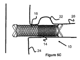
図5Cは、動脈瘤22をもつ側方血管枝26を有する主血管24を示している。動脈瘤22が分岐領域に非常に近接して位置しているので、分岐領域から主血管24内へ突き出さないようなステントを留置することは難しいかもしれない。この点で、低空隙率側の領域14は動脈瘤を横切って配置することができ、他方、高空隙率側の領域16は、たとえステント10が血管枝26の外側に位置して主血管24を塞いだとしても、なおも血管26内の血流を許容にするように近位側に配置することができる。
FIG. 5C shows a
編組ステントがレーザーカットステントに優るいくつかの利点をもたらすことは注目すべきである。例えば、編組ステントは通常そのレーザーカットされた対応物ほど厚くない(編組ワイヤは一般的にレーザーカット管より薄い可能性がある)ので、編組ステントは一般的により柔軟である。編組ステントの強度と柔軟性は、通常、様々な要因(すなわち、編組み内部のワイヤ径、よこ入れ数および密度(通常、PPI、すなわちインチ当りよこ入れ率として測定される)、使用されたワイヤの数、編組みパターンなど)を制御することによってカスタマイズすることができる。しかしながら、編組ステントは、レーザーカットステントの一般的により厚い、またはより密集したプロフィールに起因するレーザーカットステントの全体強度を欠いている可能性がある。 It should be noted that braided stents provide several advantages over laser-cut stents. For example, braided stents are generally more flexible because braided stents are usually not as thick as their laser cut counterparts (braided wires may generally be thinner than laser cut tubes). The strength and flexibility of a braided stent is usually determined by various factors (ie wire diameter inside braid, number of warps and density (usually measured as PPI, ie the rate of warping per inch), wire used Can be customized by controlling the number of braids, braid patterns etc. However, braided stents may lack the overall strength of laser cut stents due to the generally thicker or more dense profile of laser cut stents.
編組ステントが編組みに沿った交点に機械的結束を備え、それによりこれらの合流点における強度を増大させることによって、編組ステントの厚さまたは密度を増大させる(それによりその強度を増大させる)ことができる。編組ステントが、ステントを作るように編み組まれた、または編まれた1本以上のフィラメントからなる一方で、レーザーカットステントは、固体材料をその後にレーザーカットしてなっている。レーザーカットステントは固体材料からなるので、力が、バネに対する力と同様に、ステントを介して効果的に伝達され、それにより、このステントは編組ステントよりもよりバネのように作用し、より効果的にステントを介して力を伝達する傾向がある。ステントがカテーテルから押される際に押圧力がステントを介して効果的に伝達されるこの品質は、ステント展開に役立つ。この品質は、ステントが、バネに似て、変位に抵抗する自身の内力を有するので、ステント移動を防止するためにも役立つ。 Increasing the thickness or density of the braided stent (and thereby increasing its strength) by providing mechanical bonds at the points of intersection along the braid, thereby increasing the strength at these junctions Can. While a braided stent consists of one or more filaments braided or braided to make a stent, a laser cut stent is then laser cut of a solid material. Because the laser-cut stent is made of solid material, the force is transmitted effectively through the stent as well as the force on the spring, so the stent acts more like a spring than a braided stent and is more effective Tend to transmit forces through the stent. This quality of effective transfer of pressure through the stent as the stent is pushed from the catheter aids in stent deployment. This quality also helps to prevent stent migration as the stent, like a spring, has its own internal force that resists displacement.
これらの結束は、コイル状の結束が使用される場合にバネのような効果をもたらす。コイル状の結束は、実際には、結束が位置する局所の合流点でバネのように作用することになるからである。したがって、ステント展開に役立つことに加えてステントの移動に対する抵抗を可能にする、より弾性的な材料品質もステントとして採用されるだろう。あるいは、機械的結束の代わりに金属またはポリマーのスリーブを使用して、ステントにさらに強度を付与することができる。 These bonds provide a spring-like effect when coiled bonds are used. This is because the coiled bonds actually act like a spring at the local junction where the bonds are located. Thus, a more elastic material quality will also be employed as a stent that allows for resistance to stent migration in addition to serving stent deployment. Alternatively, metal or polymeric sleeves can be used instead of mechanical ties to provide additional strength to the stent.
図6Aないし図6Fは、編組ステントの交点の周りで使用される機械的結束30の様々な構成を示す。機械的結束30は、大きいほうのコイル33(例えば、2本のステントワイヤを包むほど大きいサイズにほぼ設定された内径)に接続された、2本の小さいほうのコイル31(例えば、ステントワイヤの周りに嵌合するようにサイズ設定された相対的に小さい内径を有する)を備えていることが好ましい。小さいほうのコイル31は、ステントのどちらか同じワイヤの周りにおいてそのワイヤと交差するワイヤの両側に巻き付けることができ(図6Bおよび図6Dに図示)、または互いに交差する異なるステントワイヤ上で互いに隣接して位置させることもできる(図6A、図6C、図6Eおよび図6Fに図示)。大きいほうのコイル33は、好ましくは2本の交差するステントワイヤの周りに巻き付けられ、2本の小さいほうのコイル31との接続によって所定位置にさらに固定される。さらに、2本の小さいほうのコイル31が、大きいほうのコイル33の自由端に接続される(図6A、図6B、図6Dおよび図6E)ことも、大きいほうのコイル33の片側に接続される(図6Cおよび図6F)こともどちらも可能であることは注目すべきである。あるいは、小さいほうのコイル31と大きいほうのコイル33を、交差するステントワイヤにおいて、またはその近くで、互いに接続することなく固定することも可能である。結束30および/またはその構成要素は、ステントワイヤの周りに巻き付けられることに加えて、接着剤、溶接または同様の機構によって所定位置に固定することができる。
6A-6F illustrate various configurations of
結束の配置は、交差するステントワイヤの互いの相対的な動きに影響を与え、それにより、結束によって付与される拘束力のせいでワイヤ同士間の柔軟性を低減させる。この点で、図6Aないし図6Fに示す結束パターンはすべて、結束によって包まれていないワイヤの部分で若干の動きを可能にするとともに、結束によって包まれているワイヤの別の部分での動きを減じるという点で様々な利点をもたらす。 The placement of the tie affects the relative movement of the intersecting stent wires relative to one another, thereby reducing the flexibility between the wires due to the restraining force imparted by the tie. In this regard, the bundling patterns shown in FIGS. 6A-6F all allow some movement in the portion of the wire that is not wrapped by the bundling, as well as movement in another part of the wire that is being wrapped by the bundling. Brings various advantages in that it reduces.
結束30は、タンタル、ニチノール、ステンレス鋼、コバルトクロム、ポリマー、それらの組み合わせなど、様々な材料からなることができる。結束用に使用されるタンタルなどの放射線不透過材料の1つの利点は、生体内でステントの可視性が増すことである。所望のステント特性を生むように材料を選択することも可能である。例えば、高い強度が望ましい場合、相対的に堅い結束材料を使用することができる。よりバネのような効果が望ましい場合、より展性の高い材料が使用されてもよい。
The
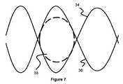
図7は編組ワイヤステント10の数本のワイヤの拡大図を示す。ワイヤ34とワイヤ36との間の隙間は、円38によって概ね表される特定の空隙サイズを形成することが好ましい。一実施例では、ワイヤは、マイクロカテーテルの直径以上の特定の空隙サイズを形成し、図4に関連して上述したように、マイクロカテーテルが空隙を通過できるように編み組まれている。一実施例では、空隙サイズは約0.01ないし0.03インチである。この空隙サイズはステント全体で相対的に一定であることも可能であるし、マイクロカテーテルを受け入れることが特に意図されたステントの一領域に限定させることも可能である。
FIG. 7 shows an enlarged view of several wires of the
図8は、2組の編組ワイヤとして一方の対34、36と他方の対42、44を備える編組ワイヤステントの拡大部分を示す。ワイヤは横断または交差し、本詳細説明で既に述べたように結束30でさらに接続されている。8ないし32本のワイヤや16本のワイヤなど、追加のワイヤも、これらのワイヤとともに編み組まれて使用することができる。結束30はすべての交点で使用されてもよいし、さもなければ、ステント全体を通じて強度増加が望ましいステント領域に周期的に配置されてもよい。ワイヤは結束された交点40同士の間で可動であるが、その結束はワイヤ交点を固定するように作用し、それにより、これらの交点での一方のワイヤの他方のワイヤに対する滑りまた移動を防止する。これら結束点は一般に、それら結束点がもたらす拘束力により径方向力の増大をもたらし、したがって、レーザーカットステントの場合に見られるバネ効果に類似する局所性のバネ効果を生じる。
FIG. 8 shows an enlarged portion of a braided wire stent comprising one
結束30の変形例も考えられる。一実施形態では、編組ステントワイヤの1本が相対的に粗い表面を(当該ワイヤの全長で、またはワイヤ同士が重なり合う選択された部分に)有する。粗い部分はワイヤの摩擦を増大させ、それにより、粗い領域と重なり合う、または接触する他のワイヤの動きを制限する。別の実施形態では、粗いワイヤが他の滑らかなワイヤに接着され、機械的結束なしで拘束力をもたらす。別の実施形態では、重なり合うステントワイヤの両方が重なり合う粗い部分を有し、かつ/または互いに結合される。
A variant of the
図9に示す結束30の別の実施形態では、結束30が3本以上のステントワイヤに接続して、ステントに対する拘束力をさらに増大させている。
In another embodiment of a
別の実施形態では、機械的結束30は、重なり合うステントワイヤ34、36の交点において両方ではなく一方の周りに巻き付けられる。この場合、両方のワイヤ34,36が機械的に結束される場合ほど拘束力をもたらさないが、2本のワイヤ34、36間(例えば、小さいほうのコイル部分31とワイヤ36との間)に摩擦を発生させながら、より大きな柔軟性を可能にする。さらに別の実施形態では、両方のワイヤ34、36が、この結束30と、結束同士を結合する接着剤を備えている。あるいは、2本のワイヤは溶接されるか、またはワイヤが出会う合流点において接着剤で結合される。
In another embodiment,
図1ないし図4および関連する詳細説明は、連結可能な空隙率の異なるステントからなる空隙率の異なる領域を有するステントについて述べた。以下の実施形態は、複数のステントを連結させて、複数の部分からなる単一のステントを作る技術について説明する。 1 to 4 and the related detailed description have described a stent having regions of different porosity that consist of stents of different connectable porosity. The following embodiments describe techniques for linking multiple stents to make a single multi-piece stent.
2つのステントまたは管状の編まれた部分が、上述したように両者を組み合わせてより長いステントを作るためにレーザー溶接されてもよい。図11は、ステントの2つの異なる編まれた部分間の例示の界面または接続点の拡大図を示す。2本のワイヤ46A、46Bなど、ステント部分46のワイヤは、ワイヤ48A、48Bなど、ステント部分48のワイヤに溶接されている。あるいは、溶接の代わりに、または溶接に加えて、機械的結束または接着剤結合が使用されてもよい。一実施例では、連結されたステント部分が、長手方向に可変の空隙率プロフィールを有する(すなわち、図1および図2のステントと同様の)ステントを作るために、それぞれ異なる空隙率を有する。別の実施例では、ステント部分同士が同様の空隙率を有し、連結されて、同様の空隙率プロフィールを有する1本のより長いステントを作る。
Two stents or tubular braided sections may be laser welded to combine the two as described above to make a longer stent. FIG. 11 shows a close-up view of an exemplary interface or connection point between two different braided portions of a stent. The wires of
レーザー溶接の代わりに、図12に示すように、ワイヤの端部同士がコイル54で結合されていてもよい。この接続技術は2本のワイヤの間に小さい範囲の動きを与えるが、それでもワイヤ同士を連結させる。各ワイヤは、ワイヤの終端に拡大部分52A、52Bを有するとともに、この終端の近位のどこかにより大きな拡大領域50A、50B(例えば、球状、球根状または同様の形状)を有する。コイル54(またはスリーブ)は、拡大部分52A、52Bがコイル54から引き抜かれることができないように、拡大部分52Aと拡大部分52Bの間でワイヤの周りに巻き付けられている。大きいほうの拡大領域50A、50Bは、拡大領域52A、52Bと接触して領域50A、50Bを越えるワイヤの動きを防止することができる停止または移動制限特徴を作っている。この点に関して、ワイヤ同士は互いに対して小程度の動き(すなわち、コイル54と領域50A、50Bとの間の間隔)を有していてもよい。
Instead of laser welding, as shown in FIG. 12, the ends of the wire may be connected by a
各ワイヤの終端の拡大部分50A、50Bが、一方のワイヤの他方のワイヤに対するスライド可能な距離の限界を提供する(例えば、1本のワイヤが拡大部分に当たるまで、ワイヤはスライド自在である)ことになるので、終端の近位の小さいほうの拡大領域50A、50Bおよび結合機構(例えば、コイルまたはスリーブ)が任意であることは理解されるべきである。しかしながら、バインダー(例えば、コイルまたはスリーブ)並びに小さいほうの拡大領域52A、52Bの利点は、ワイヤが拡大部分50A、50Bと接触するまで互いに対してスライドしきった時に、ワイヤの周りにバインダーコイル54を備えることで、ワイヤが拡大部分からの接触力に応じて径方向外側に押し出さないで、拡大部分に対して離れず、それにより、ワイヤの径方向の動きを抑制することが保証されることである。小さいほうの拡大領域52A、52Bは、バインダー54の移動を制限することにより、バインダーが滑って外れるのを防止する。バインダー54は、コイルまたはスリーブに加えて、抵抗溶接されたカプリング管であってもよい。
That the
図13は、第2のステントを(図3および図4など、本詳細説明で既に述べたように)送達させることができる空隙29Aの別の実施形態を示し、空隙29Aは、領域29aを取り巻くワイヤ上に配置された数個の放射線不透過マーカーコイル56によって形成され、領域29aは、別のステントの進入を受け入れるように(すなわち、yステント留置の目的で)より大きな空隙サイズ領域を有している。あるいは、マーカーバンドが使用されてもよい。領域29aはステントに沿ってどこに位置していてもよく、例えば、ステントの1個のセルを構成していても、2個以上のセルを備えたステントの一部を構成していてもよい。この概念は、ステントの一部がマイクロカテーテルを受け入れるのに(すなわち、塞栓送達のために)十分大きな空隙サイズを有する低空隙率ステント用に使用することができる。より大きな空隙サイズを有するステント部分は、ステントを抜けてマイクロカテーテルを配置すべき場所をユーザーがわかるように、放射線不透過コイルまたはマーカーバンドで包むことができる。第2のステントを受け入れる第1のステントの領域をユーザーが視覚化できるように、空隙29の周りの領域のコイルのワイヤ上に、タンタルなどの放射線不透過材料を使用することができる。 FIG. 13 shows another embodiment of a void 29A capable of delivering a second stent (as already described in this detailed description, such as FIGS. 3 and 4), wherein void 29A surrounds area 29a. Formed by several radiopaque marker coils 56 disposed on the wire, area 29a has a larger void size area to accommodate the entry of another stent (ie, for the purpose of y stent placement) ing. Alternatively, marker bands may be used. The region 29a may be located anywhere along the stent, for example, it may constitute one cell of the stent or may constitute part of a stent comprising two or more cells. This concept can be used for low porosity stents, where a portion of the stent has a void size large enough to receive the microcatheter (ie, for embolic delivery). A stent portion having a larger void size can be wrapped with a radiopaque coil or marker band so that the user knows where to exit the stent and place the microcatheter. A radiopaque material such as tantalum can be used on the wire of the coil in the area around the void 29 so that the user can visualize the area of the first stent that receives the second stent.
これらの実施例では、領域29aがステントの残りの空隙よりも大きな空隙サイズを有すると説明されているが、それらに代わる実施形態も可能である。空隙29Aをより大きなサイズに伸ばして別のステントの進入を受け入れさせるように、領域29Aが緩く構成されていてもよい。あるいは、ステント全体を通じて、各空隙のサイズを別のステントの進入を受け入れられるほど大きくすることができる。すなわち、ステントは、ステントの幅全体を通じて、空隙から別のステントの進入を受け入れるようにサイズ設定された大きな空隙サイズを有する。あるいは、領域29Aがステントの残りの部分より大きな空隙サイズを有していてもよく、空隙サイズを伸長可能にするように緩く構成されていてもよい。この緩い構成は、領域29A内のワイヤの互いに対する動きを規制せず、ワイヤが動いて領域内への別のステントの進入を受け入れ可能にすることによって可能になる。一実施例では、領域29A内でのワイヤの自由な動きを最大にするために、領域29aが、領域内の編組ワイヤ間で接着剤、結束、または他の結合機構を利用しない。
Although in these examples the area 29a is described as having a void size larger than the remaining void of the stent, alternative embodiments are possible.
図14に示すように、張り出した端部を利用するステント59もある。張り出した端部の恩恵の中には、血管内での保持力または固定強度が含まれる。張り出した端部のステント同士を直線状に連結させることは直径の増大になる場合があり、均一の直径を維持することをさらに困難にする場合がある。これら張り出した端部のステント59同士を連結させるために、多くの選択肢が利用可能である。一選択肢では、ステント59の一端を切断して張り出しをなくし(例えば、一端で張り出したループを保持して、他端でステントを切断してループをなくし)、その後、次のテントを切断位置に連結させる。
As shown in FIG. 14, there is also a
2つのステントの1つ以上の張り出した端部同士を接続する別の選択肢を図14および図15に示す。ステントは、長いほうのループ状の張り出し58(図面では、3つの長いほうの張り出しを備えているが、よる多数またはより少数の張り出しも可能である)と、短いほうの張り出し60(図面では、3つの短いほうの張り出しを備えている)とを有する。図面では、短いほうの張り出しと長いほうの張り出しが交互に並んでいる、すなわち、長いほうの張り出しの隣にある短いほうの張り出しの隣に長いほうの張り出しがある等である。ワイヤ62が、一端で1つの短い張り出し60に接続し、他端で1つの長い張り出し58に接続する。ワイヤは張り出しに対して溶接、結束、または接着させることができる。あるいは、図14に記載したものと類似したシステムを、ワイヤ62を張り出しのワイヤに固定するために使用することができる。ワイヤ62が両方の張り出しに接続されているので、ワイヤに対する引っ張り作用により、短い張り出しと長い張り出しの両方がつぶれることになる。
Another option for connecting one or more overhanging ends of two stents is shown in FIGS. 14 and 15. The stent has a longer loop-like overhang 58 (in the drawing, there are three longer overhangs, but more or fewer overhangs are possible) and a shorter overhang 60 (in the figure) With three shorter overhangs). In the drawings, the short overhangs and the long overhangs alternate, that is, there is a longer overhang next to the shorter overhang next to the longer overhang, and so on.
図15において、要素58aは第1のステントの長いほうの張り出し58の1つからのワイヤを識別する。張り出しは好ましくはv字形状をしており、「v」字の2つの部分のそれぞれがワイヤ62を巻き付けているか、さもなければ連結させている。実施例の場合、3つの長いほうの張り出し58と3つの短いほうの張り出し60が示された図14において、各ワイヤは長い張り出しの1つと短い張り出しの1つに接続し、張り出し毎に2本のワイヤが使用されるので、たった6本のワイヤ62しか使用されていない。言い替えれば、ワイヤ62の数はステントの張り出しの総数と一致する。要素64は第2のステントからのワイヤを示し、ステントの一端の張り出し要素か、または非張り出し部分(すなわち、上述したように、張り出しがステントから切断された部分、または張り出しを利用しない別のステント)である可能性がある。上述したように大きい張り出しを使用して2つのステントを接続する1つの利点は、図15から分かるように、大きい張り出しが相対的に大きい空隙開口を有することである。これにより、大きい張り出しは、図3における空隙29と同様に、すなわち、血管分岐部でのyステント留置など、様々な目的で別のステントを導入することができる導管として使用することができる。
In FIG. 15, element 58a identifies the wire from one of the longer overhangs 58 of the first stent. The overhangs are preferably v-shaped, each of the two portions of the "v" being wound or otherwise coupled to the
なお、張り出しの終端またはその近くでは、2つのワイヤ端が合流する。したがって、6つの張り出し(すなわち、3つの大きい張り出しと3つの小さい張り出し)を有する編組みは、12本のワイヤの編組みからなることになる。8つの張り出し(すなわち、4つの大きい張り出しと4つの小さい張り出し)を有する編組みは、16本のワイヤの編組みからなることになる。 At or near the end of the overhang, the two wire ends merge. Thus, a braid having six overhangs (ie, three large overhangs and three small overhangs) would consist of a braid of 12 wires. A braid having eight overhangs (ie, four large overhangs and four small overhangs) will consist of a braid of 16 wires.
2つのステントを連結させる場合に一方のステントともう一方のステントのワイヤが揃っていることは必要とされていないが、ステントから突出して血管損傷を起こすおそれのある、結ばれていない未連結のワイヤが存在しないこと(すなわち、連結時に2つの異なるステントの構成ワイヤ間の1対1の接続点)を保証するためには、ワイヤが揃っていることが一般的に望ましい。例えば、12本のワイヤを備えたワイヤ編組みであれば、12本のワイヤを備えた別のワイヤ編組に連結されるのが最良になる。それは、一方のステント中の各ワイヤが、使い残しのワイヤのない他方のステント中の別のワイヤに連結することになるからである。 When connecting two stents, it is not necessary that the wire of one stent and the other of the stent be in alignment, but it is not connected and unconnected, which may protrude from the stent and cause vascular damage. It is generally desirable that the wires be aligned to ensure that the wires are not present (ie, a one-to-one connection point between the component wires of two different stents when connected). For example, a wire braid with twelve wires would be best coupled to another wire braid with twelve wires. That is because each wire in one stent will connect to another wire in the other stent without any remaining wires.
張り出しを有する2つのステントを接合させる場合、ステントは張り出しにおいて接合させることができる。大きいループの張り出しと短いループの張り出しの両方を有する2つのステントを接合させる場合、ステントは、一方のステントの大きい張り出しが他方のステントの大きい張り出しと重なる交点で接合させることができる。このことは、大きい張り出し部分が、例えば、短い張り出し部分よりもステントからより外側へ突出する傾向があるので可能である。あるいは、ループの張り出しはループを構成する構成ワイヤを露出させるように切断することができ、ワイヤはその後、直ぐ上方で述べたように、1対1の配置で互いに直接連結させることができる。 When joining two stents having an overhang, the stent can be joined at the overhang. When joining two stents having both large loop overhangs and short loop overhangs, the stent can be joined at the intersection where the large overhang of one stent overlaps the large overhang of the other stent. This is possible because larger overhangs tend to project more outward from the stent than, for example, shorter overhangs. Alternatively, the overhang of the loop can be cut to expose the constituent wires that make up the loop, and the wires can then be directly connected to one another in a one-to-one arrangement, as described immediately above.
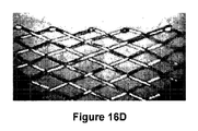
上記の説明は、少なくとも一方のステントが切断される場合に2つのステントを連結させる方法に言及している。ステントはいくつかの理由によっても切断される場合がある。一実施例では、ステントは、マンドレル上で連続的に編まれた後、複数のステントを作るために、選択された部分に切断されることがある。しかしながら、ステントが1本以上のワイヤまたはワイヤの編組みからなる場合には、ステントの切断は、血管内で外傷を引き起こすおそれのある開いたワイヤ端を生じることになる。ステントの切断は、血管系内で外傷を引き起こすおそれのあるワイヤのほつれを起こす場合もある。ワイヤの切断部分同士を溶接し、閉じた端部構成を形成して、血管系内の外傷を最小限にしてもよい。切断と溶接のパターンは、図16aないし図16mに示すように、多くの形状を呈することができる。閉じた端部デザインは、ステントを回収するために機械装置が係合することができる閉じた領域表面を提供することによって、展開後/展開時のステントの回収可能性も向上させる。一実施形態では、内層と外層を備えた二層ステントがステントの内層において閉じた端部デザインを利用する。機械的結束(すなわち、螺旋状のコイル巻き付けや他の結束)をステントの長さ沿いに使用して内層と外層を結合させることができ、また、結束を閉じた端部領域またはその近くに配置して、一方の層が他方の層に対してずれるのを防止することもできる。 The above description refers to a method of joining two stents when at least one of the stents is cut. A stent may also be cut for several reasons. In one embodiment, the stent may be cut into selected portions to make multiple stents after being continuously knitted on a mandrel. However, if the stent consists of one or more wires or a braid of wires, cutting the stent will result in open wire ends that can cause trauma within the blood vessel. Cutting the stent can also cause fraying of the wire which can cause trauma within the vasculature. The cut portions of the wire may be welded together to form a closed end configuration to minimize trauma within the vasculature. The cutting and welding patterns can take on many shapes, as shown in Figures 16a to 16m. The closed end design also improves the recoverability of the stent after deployment / deployment by providing a closed area surface that the mechanical device can engage to retrieve the stent. In one embodiment, a two-layer stent with inner and outer layers utilizes a closed end design at the inner layer of the stent. A mechanical tie (ie, a helical coil wrap or other tie) can be used along the length of the stent to bond the inner and outer layers and place the tie at or near the closed end area It is also possible to prevent one layer from shifting relative to the other layer.
ほつれた端部を防止する別の構成を図18ないし図20に示す。図18に示す一実施形態は、隣接した目穴に接続する目穴を使用することに関している。ステント/補綴材の外層を構成するワイヤが、ワイヤをワイヤ自体に向かって引き戻し、位置76で溶接することにより、目穴74を形成するように屈曲または成形される。一方のワイヤ端部の目穴を最初に作った後、第2のワイヤを第1のワイヤの端部の目穴に挿入し、最後に第2のワイヤを位置76で溶接して第2の目穴を作ることにより、目穴同士を接続する。また、ワイヤは、目穴領域のサイズ次第で互いに対して少し自由に動く。それにより、この構成はステント/補綴材の柔軟性に関していくつかの利点をもたらす。
An alternative arrangement for preventing frayed ends is shown in FIGS. 18-20. One embodiment shown in FIG. 18 relates to the use of eyelets connecting to adjacent eyeholes. The wire comprising the outer layer of the stent / prosthesis is bent or shaped to form
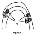
他の変形例は、一方のワイヤを他方のワイヤに対して引き戻し、ワイヤ同士を溶接することに関している。この配置を図19に示し、図19では、1箇所以上の位置78でワイヤ同士が溶接されている。別の構成は、図20に示すように、ステントの両端を引き戻し、より近位側の位置で両方のステント端を他方のワイヤに溶接することに関している。
Another variation relates to pulling back one wire against the other and welding the wires together. This arrangement is shown in FIG. 19, in which the wires are welded at one or
多層編組ステント(すなわち、編組み内層と編組み外層とを有する二層ステント)では、層のいずれかまたは両方が、開いたワイヤ端による外傷を低減させるように溶接構成を利用してもよい。一実施例では、ステント(図16の二層ステントを参照)の内層が一端または両端が切断された編組みからなり、ステントの外層が各端に張り出したループを有する別個の編組みからなり、外層は両端とも切断されない。ステントの内層は、血管損傷を最小限にするために、溶接端を利用してもよい。一実施例では、ワイヤ端に滑らかな輪郭を作って血管損傷の可能性を最小限にするために、組み合わせの2つのワイヤ端の合流点で、点溶接または丸めた形状を導入可能なあらゆる熱処理が使用される。別の実施例では、ステントが編組材料の1層のみからなり、ステントが両端で切断されており、血管損傷を減じるために、切断されたワイヤの端部がほつれた端部や開いた端部を防止するよう溶接される。 In a multi-layered braided stent (i.e., a bi-layer stent having a braided inner layer and a braided outer layer), either or both of the layers may utilize a welded configuration to reduce trauma from open wire ends. In one embodiment, the inner layer of the stent (see bi-layer stent in FIG. 16) consists of a braid cut at one or both ends and the outer layer of the stent consists of separate braids with overhanging loops at each end, The outer layer is not cut at both ends. The inner layer of the stent may utilize a welded end to minimize vascular injury. In one embodiment, any heat treatment that can introduce point welds or rounded shapes at the confluence of the two wire ends of the combination to create a smooth profile at the wire ends to minimize the possibility of vascular injury Is used. In another embodiment, the stent consists of only one layer of braided material, the stent is cut at both ends and the cut end of the wire is frayed or open to reduce vascular damage. Are welded to prevent.
図17Aおよび図17Bは、ステントを通じて螺旋状に巻かれたワイヤ105を有するステントを示す。好ましくは、このワイヤは、生体内でのステントの可視化を向上させるために放射線不透過性(すなわち、タンタル)である。図17Aでは、ワイヤ105が一層ステント内に巻かれており、図17Bでは、ワイヤ105が内層編組みと外層編組みとを備えた二層ステントを通じて巻かれている。ワイヤ105が二層ステントを通じて巻かれる場合、ワイヤは両方の層を貫いて上下(すなわち、外層の上、内層の下など)に巻かれる。
17A and 17B show a stent having a
もう1本のワイヤが逆のやり方で巻かれてもよく、そのワイヤは、ニチノールからなっていても、放射線不透過性であっても(すなわち、タンタルからなっていても)よい。ステントが切欠き部分70を取り巻く2つの突出部分66、68を備える図16Aに示す構成など、溶接されたステント端部構成を考慮すれば、逆のやり方で巻かれた第2のワイヤを使用することは重要である。ワイヤ105がこのステント内で1方向にのみ巻かれている場合、ワイヤがステントを通じて巻かれる外側表面積を低下させる切欠き部分70の存在のせいで、部分66、68のいずれかは、その部分内にワイヤ105が巻かれていないことになる。部分66、68のいずれかに放射線不透過ワイヤ105の恩恵(すなわち、放射線不透過性の向上)を得させるために、別個の放射線不透過ワイヤをこの部分内で使用してもよい。あるいは、複数のワイヤ(すなわち、複数の放射線不透過ワイヤ、または放射線不透過ワイヤ1本と非放射線不透過ワイヤ1本)をこの部分に使用してもよい。あるいは、もう1本のワイヤをワイヤ105とは逆のやり方で巻くこともできる。この第2のワイヤは逆のやり方で巻かれるので、ワイヤ105を欠いた部分に達することになる。
Another wire may be wound in the opposite manner, and the wire may be made of nitinol or radiopaque (i.e., made of tantalum). Given a welded stent end configuration, such as the configuration shown in FIG. 16A, such as the configuration shown in FIG. 16A, in which the stent comprises two protruding
分流ステントは動脈瘤などの血管の問題を効果的に処理するかもしれないが、しかしながら、一旦ステントが製造されると、空隙率が決まってしまう。以下の実施形態は、ステントとともに使用され、ステントの空隙率を効果的に低下させるインサート、およびそのようなインサートを利用したステントについて説明する。 Split-flow stents may effectively treat vascular problems such as aneurysms, however, once the stent is manufactured, porosity may be determined. The following embodiments describe an insert for use with a stent to effectively reduce the porosity of the stent, and a stent utilizing such an insert.
図21はステントインサートとして使用される薄膜110を示す。薄膜110は、螺旋状または渦巻き状の形状を作るために、ステント直径に近い筒体またはマンドレル112の周りに巻き付けることができる。薄膜はポリマー、例えば、PTFEであってもよく、薄膜の特性によっては完全にカスタマイズ可能な空隙率を有していてもよい。薄膜空隙率は、薄膜に様々な大きさの空隙を取り入れることによって制御可能であったり、薄膜の材料特性もしくは厚さによって、またはこれらの要因の組み合わせによって制御可能であったりする。あるいは、薄膜は金属のメッシュまたは布地材料であってもよい。
FIG. 21 shows a
図22は、1本以上のワイヤ204から形成された内層と、1本以上のワイヤ102から形成された外層とを備えた二層ステント100を示す。特定の実施形態では、外層は、外層の全長を通じて前後に曲がりくねった1本のワイヤ102を備えている。例えば、外層は、ステントの長さ全体にわたって2方向に進むパターンを作るように折り返して戻る1本のワイヤ102を備えていてもよい。別の実施例では、外層は2本以上のワイヤ102を備えている。
FIG. 22 shows a two-
図23は図2に示すステント100の一部分の拡大図を示す。ステント100は、図26に示すように、ワイヤ102に並んでまたは平行に配置され、外層ワイヤ102の上と内層ワイヤ204の下を交互に進み、それによって内層と外層を接続する、1本以上の支持ワイヤ814を使用してもよい。ワイヤ102の長さ沿いの様々な場所、例えば、ステントの近位側の部分および/もしくは遠位側の部分、並びに/または、図4および図5に示すように、支持ワイヤ814の始点と終点におけるワイヤ102の周りに、支持ワイヤ814によって1つ以上の巻線816が形成されてもよい。巻線816は、ワイヤ814の近位端と遠位端との間でワイヤ814の長さ沿いの1箇所以上の場所で形成されていてもよい。
FIG. 23 shows an enlarged view of a portion of the
複数の支持ワイヤ814がステントの全長を通じて使用されてもよく、例えば、支持ワイヤは、外層を構成するワイヤ102沿いの、または別々の構成ワイヤ要素102沿いの別々の個所から始まることができる。特定の実施形態では、特定のワイヤ102と平行する支持ワイヤ814が、ワイヤ814の巻線816によって同じワイヤ102に固定され、ステント100の内層と外層の間でポケットまたはスリーブが形成される物理的な境界として機能する。これらのポケット内に、1枚以上の薄膜110が配置または固定されてもよい。
A plurality of
図27は、陰影で示す2本の支持ワイヤ814を有する二層ステントを示す。各支持ワイヤ814は、別のワイヤ102または同じワイヤ102の別の長さ部分と平行する。支持ワイヤ814は、ステントの内層と外層との間に、薄膜が位置して固定されるポケットを作る。
FIG. 27 shows a bi-layer stent having two
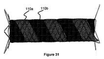
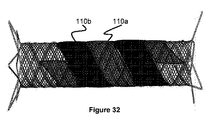
図28ないし図32はステントとともに使用される様々な薄膜構成を示す。これらの図は、実施例として提示されており、可能性のある薄膜構成を限定することを意図していない。図28および図29は、薄膜10aまたは薄膜10bがステントの内層と外層の間のそれぞれ異なるポケット内に位置している2つの構成を示す。図30ないし図32は薄膜110aおよび薄膜110bの両方が位置する様々な構成を示す。2枚の薄膜を示しているが、より多くの薄膜が使用されてもよい。複数の薄膜を利用する構成は、それぞれ異なる空隙率を有する薄膜を利用して、ステントの長さに沿って可変の空隙率を提供することができる。薄膜はステントの全長またはステントの一部分のみに及んでもよい。
Figures 28-32 show various thin film configurations used with a stent. These figures are presented as examples and are not intended to limit the possible thin film configurations. Figures 28 and 29 show two configurations in which the
別の実施形態では、1枚以上のインサートが薬剤溶出用であってもよい。 In another embodiment, one or more inserts may be for drug elution.
他の実施形態では、一層ステント、二層ステントまたは多層(すなわち、3層以上)ステントが1枚以上のインサートを利用してもよい。インサートが最も内側のステント層の内面に沿って(または一層ステントの内面に沿って)、いずれかの層間に、または外層の外面(または一層ステントの外面)に位置し得ることが考えられる。2層の間にインサートが位置する実施形態では、インサートが両方の隣接層に、または隣接層の一方のみに接続し得ることが考えられる。そのような接続のいずれも、上述したような「ポケット」の作成によって、機械的結束もしくは編み込みによって、または接着剤によって達成することができる。 In other embodiments, a single layer stent, a double layer stent or a multiple layer (ie, three or more layers) stent may utilize one or more inserts. It is contemplated that the insert may be located along the inner surface of the innermost stent layer (or along the inner surface of the single layer stent), between any layers, or on the outer surface of the outer layer (or the outer surface of the single layer stent). In embodiments where the insert is located between two layers, it is contemplated that the insert may be connected to both adjacent layers or to only one of the adjacent layers. Any such connection can be achieved by mechanical bundling or knitting, or by an adhesive, by the creation of "pockets" as described above.
他の実施形態では、一層ステント、二層ステントまたは多層(すなわち、3層以上)ステントが薬剤溶出性インサートを利用してもよい。 In other embodiments, a single layer stent, a double layer stent or a multiple layer (ie, three or more layers) stent may utilize a drug eluting insert.
インサートは一層ステント、二層ステント、または3層以上を有するステントで使用されてもよい。一層ステントの例は、ステントが1層だけ(すなわち、1つの編組み層)を利用する場合である。一層ステントの場合、インサートは接着剤、熱処理、または他の技術によってステントの内面または外面に添着されてもよい。二層または他の多層(すなわち、3以上の層)のステントの場合、インサートは接着剤、熱処理、機械的結束、または他の技術によってステントの内面上、層間または外面上に位置してもよい。あるいは、インサートは、ステントの閉塞的特性をさらに増大させるために、ステントの複数の表面上に位置することができる。一実施例では、二層ステントが、内層表面に薄膜1枚と、内層と外層の間に薄膜1枚を備えることができる。別の実施例では、二層ステントが、内層と外層の間に薄膜1枚と、外層表面に薄膜1枚を備えることができる。別の実施例では、二層ステントが、内層表面に薄膜1枚と、外層表面に薄膜1枚を備えることができる。別の実施例では、二層ステントが、内層および外層の表面と、内層と外層の間にも薄膜を備えることができる。 The insert may be used in a single layer stent, a double layer stent, or a stent having three or more layers. An example of a single layer stent is where the stent utilizes only one layer (i.e., one braided layer). In the case of a single layer stent, the insert may be affixed to the inner or outer surface of the stent by adhesive, heat treatment, or other techniques. In the case of a two-layer or other multi-layered (ie three or more layers) stent, the inserts may be located on the inner, interlayer or outer surface of the stent by adhesive, heat treatment, mechanical bonding or other techniques . Alternatively, the inserts can be located on multiple surfaces of the stent to further enhance the occlusive properties of the stent. In one embodiment, a dual layer stent can include one thin film on the inner layer surface and one thin film between the inner and outer layers. In another embodiment, a bi-layer stent can include one membrane between the inner and outer layers and one membrane on the outer layer surface. In another embodiment, a two-layer stent can include one thin film on the inner layer surface and one thin film on the outer layer surface. In another embodiment, a bi-layer stent can also include a thin film between the inner and outer layer surfaces and between the inner and outer layers.
一実施形態では、インサートが螺旋状または渦巻き状の形状を有すると説明したが、他の形状も可能である。例えば、1つ以上のステント層の間で編み込まれるか、さもなければ接続された複数の細長いインサート部材からインサートを構成することもできる。別の実施例では、インサートが、ステントの外面、内面または層間に位置することを可能にする管状を有していてもよい。 In one embodiment, although the insert has been described as having a helical or spiral shape, other shapes are possible. For example, the insert may be comprised of a plurality of elongated insert members that are woven or otherwise connected between one or more stent layers. In another embodiment, the insert may have a tubular shape that allows it to be located on the outer surface, the inner surface or between the layers of the stent.
編組ステントについて説明してきたが、他の種類のステントも可能であることは理解されるべきである。例えば、ステントがレーザーカットされた管もしくはシート、または編組みではないポリマーベースのステントから形成されてもよい。 Although a braided stent has been described, it should be understood that other types of stents are possible. For example, the stent may be formed from a laser cut tube or sheet, or a non-braided polymer based stent.
発明を特定の実施形態および応用例に関連して説明してきたが、当業者は、本教示に照らして、請求項にかかる発明の精神または範囲を逸脱することなく、さらなる実施形態および変形を生み出すことができる。したがって、本書における図面および説明が発明の理解を容易にするために例として提示されたものであり、発明の範囲を限定するものと解釈されるべきではないことは理解されるはずである。 While the invention has been described in conjunction with specific embodiments and applications, those of ordinary skill in the art, in light of the present teachings, may create additional embodiments and variations without departing from the spirit or scope of the claimed invention. be able to. Accordingly, it should be understood that the drawings and the description herein are provided as an example to facilitate understanding of the invention and should not be construed as limiting the scope of the invention.
Claims (10)
第1の空隙率を有する第1の領域と、前記第1の領域に隣接する、前記第1の空隙率より高い第2の空隙率を有する第2の領域とを有し;、
前記第1の領域と前記第2の領域の双方が、それ自体と編まれた1本のワイヤから形成されて、1本のステントマンドレル上で、同時に編まれた単一の環形状を形成しており;
前記第1の領域が複数の機械的結束をさらに備え、前記複数の機械的結束のそれぞれは、前記ワイヤの第1の部分と、前記第1の部分と重なる前記ワイヤの第2の部分とを接続し;
前記複数の機械的結束のそれぞれが、第1の内径を有し且つ前記第1の部分の周りにのみ配置された第1のコイルをさらに含み;及び
前記複数の機械的結束のそれぞれが、前記第1の内径より大きい第2の内径を有する第2のコイルをさらに含み、前記第2のコイルは前記第1のコイルに接続されていることを特徴とするステント。 A stent,
A first region having a first porosity, and a second region adjacent to the first region and having a second porosity higher than the first porosity;
Both the first area and the second area are formed from a single wire braided with itself to form a single annular shape simultaneously braided on a single stent mandrel And
The first region further comprises a plurality of mechanical ties, each of the plurality of mechanical ties comprising a first portion of the wire and a second portion of the wire overlapping the first portion. connection;
Each of the plurality of mechanical ties further includes a first coil having a first inner diameter and disposed only around the first portion; and each of the plurality of mechanical ties is A stent further comprising a second coil having a second inner diameter greater than the first inner diameter, the second coil being connected to the first coil.
1本のマンドレル上で編まれ、管状の第1の空隙率を有する編まれた第1の領域と前記第1の空隙率より高い第2の空隙率を有する編まれた第2の領域の双方を単独で形成する、1本のワイヤを含み;
前記管状の第1の領域が複数の機械的結束をさらに備え、前記複数の機械的結束のそれぞれは、前記ワイヤの第1の部分と、前記第1の部分と重なる前記ワイヤの第2の部分とを接続し、
前記複数の機械的結束のそれぞれが、第1の内径を有し且つ前記第1の部分の周りにのみ配置されている第1のコイルをさらに含み;及び
前記複数の機械的結束のそれぞれが、前記第1の内径より大きい第2の内径を有する第2のコイルをさらに含み、前記第2のコイルは前記第1のコイルに接続されている、ステント。 A stent,
Both a woven first area having a tubular first porosity and a second woven area having a second porosity higher than the first porosity, knitted on a single mandrel Form a single wire, including:
The tubular first region further comprises a plurality of mechanical ties, each of the plurality of mechanical ties comprising a first portion of the wire and a second portion of the wire overlapping the first portion Connect with
Each of the plurality of mechanical ties further includes a first coil having a first inner diameter and disposed only around the first portion; and each of the plurality of mechanical ties comprises: The stent further comprising a second coil having a second inner diameter greater than the first inner diameter, the second coil being connected to the first coil.
Applications Claiming Priority (5)
| Application Number | Priority Date | Filing Date | Title |
|---|---|---|---|
| US201562102483P | 2015-01-12 | 2015-01-12 | |
| US62/102,483 | 2015-01-12 | ||
| US201562108699P | 2015-01-28 | 2015-01-28 | |
| US62/108,699 | 2015-01-28 | ||
| PCT/US2016/013102 WO2016115173A1 (en) | 2015-01-12 | 2016-01-12 | Stent |
Related Child Applications (1)
| Application Number | Title | Priority Date | Filing Date |
|---|---|---|---|
| JP2019120252A Division JP6796688B2 (en) | 2015-01-12 | 2019-06-27 | Stent |
Publications (3)
| Publication Number | Publication Date |
|---|---|
| JP2018505720A JP2018505720A (en) | 2018-03-01 |
| JP2018505720A5 JP2018505720A5 (en) | 2019-02-21 |
| JP6549717B2 true JP6549717B2 (en) | 2019-07-24 |
Family
ID=56366691
Family Applications (2)
| Application Number | Title | Priority Date | Filing Date |
|---|---|---|---|
| JP2017536957A Active JP6549717B2 (en) | 2015-01-12 | 2016-01-12 | Stent |
| JP2019120252A Active JP6796688B2 (en) | 2015-01-12 | 2019-06-27 | Stent |
Family Applications After (1)
| Application Number | Title | Priority Date | Filing Date |
|---|---|---|---|
| JP2019120252A Active JP6796688B2 (en) | 2015-01-12 | 2019-06-27 | Stent |
Country Status (5)
| Country | Link |
|---|---|
| US (4) | US10039655B2 (en) |
| EP (2) | EP3244843B1 (en) |
| JP (2) | JP6549717B2 (en) |
| CN (2) | CN110269729B (en) |
| WO (1) | WO2016115173A1 (en) |
Families Citing this family (58)
| Publication number | Priority date | Publication date | Assignee | Title |
|---|---|---|---|---|
| GB2494632A (en) * | 2011-09-09 | 2013-03-20 | Isis Innovation | Stent and method of inserting a stent into a delivery catheter |
| US9265512B2 (en) | 2013-12-23 | 2016-02-23 | Silk Road Medical, Inc. | Transcarotid neurovascular catheter |
| US9801644B2 (en) | 2014-01-03 | 2017-10-31 | Legacy Ventures LLC | Clot retrieval system |
| EP3142598B1 (en) | 2014-05-16 | 2020-07-08 | Veosource SA | Implantable self-cleaning blood filters |
| KR102047167B1 (en) * | 2015-01-16 | 2019-11-20 | 보스톤 싸이엔티픽 싸이메드 인코포레이티드 | Implantable Medical Devices with Reduced Mobility |
| US10426497B2 (en) | 2015-07-24 | 2019-10-01 | Route 92 Medical, Inc. | Anchoring delivery system and methods |
| US11065019B1 (en) | 2015-02-04 | 2021-07-20 | Route 92 Medical, Inc. | Aspiration catheter systems and methods of use |
| EP3620204B1 (en) | 2015-02-04 | 2022-09-14 | Route 92 Medical, Inc. | Rapid aspiration thrombectomy system |
| US10874422B2 (en) * | 2016-01-15 | 2020-12-29 | Tva Medical, Inc. | Systems and methods for increasing blood flow |
| US10183145B2 (en) | 2016-02-24 | 2019-01-22 | Incept, Llc | Enhanced flexibility neurovascular catheter |
| US10555738B2 (en) | 2016-05-18 | 2020-02-11 | Microvention, Inc. | Embolic containment |
| CN109688945B (en) | 2016-05-18 | 2022-06-24 | 微仙美国有限公司 | Embolism stopper |
| EP3531968A4 (en) * | 2016-10-27 | 2020-05-27 | Rapid Medical Ltd. | Woven wire intraluminal device |
| WO2018129194A1 (en) | 2017-01-06 | 2018-07-12 | Incept, Llc | Thromboresistant coatings for aneurysm treatment devices |
| AU2018208460B2 (en) | 2017-01-10 | 2023-03-16 | Route 92 Medical, Inc. | Aspiration catheter systems and methods of use |
| US11197770B2 (en) | 2017-05-08 | 2021-12-14 | Baylor College Of Medicine | Bifurcated flow diverter systems |
| WO2019036298A1 (en) | 2017-08-17 | 2019-02-21 | Incumedx, Inc. | Flow attenuation device |
| EP3446661B1 (en) | 2017-08-21 | 2021-12-29 | Cook Medical Technologies LLC | Braided stent crown geometry and flare |
| US10835398B2 (en) * | 2017-11-03 | 2020-11-17 | Covidien Lp | Meshes and devices for treating vascular defects |
| CN109984863B (en) | 2017-12-29 | 2020-04-07 | 先健科技(深圳)有限公司 | Double-layer blood vessel support |
| WO2019195540A2 (en) | 2018-04-04 | 2019-10-10 | Incumedx, Inc. | Embolic device with improved neck coverage |
| CA3095844A1 (en) | 2018-05-01 | 2019-11-07 | Incept, Llc | Devices and methods for removing obstructive material from an intravascular site |
| US11395665B2 (en) | 2018-05-01 | 2022-07-26 | Incept, Llc | Devices and methods for removing obstructive material, from an intravascular site |
| CN115999019A (en) | 2018-05-17 | 2023-04-25 | 92号医疗公司 | Aspiration catheter system and method of use |
| CN108836585B (en) * | 2018-05-28 | 2021-07-30 | 上海长海医院 | Y-shaped carotid stent with absorbable self-protruding membrane branch |
| KR20210016405A (en) * | 2018-05-30 | 2021-02-15 | 파운드리 이노베이션 앤드 리서치 1 리미티드 | Wireless resonant circuit and variable inductance vascular monitoring implant and fixation structure therefor |
| US11517335B2 (en) | 2018-07-06 | 2022-12-06 | Incept, Llc | Sealed neurovascular extendable catheter |
| US11471582B2 (en) | 2018-07-06 | 2022-10-18 | Incept, Llc | Vacuum transfer tool for extendable catheter |
| KR102442417B1 (en) * | 2018-09-26 | 2022-09-14 | 니혼라이프라인 가부시키가이샤 | Stents and stent grafts |
| EP3870105A4 (en) * | 2018-10-25 | 2022-08-03 | Endologix LLC | Bifurcated stent grafts, stents, and methods |
| US20200237540A1 (en) * | 2019-01-28 | 2020-07-30 | Spiros Manolidis | Stent delivery for vascular surgery |
| AU2020242051A1 (en) | 2019-03-20 | 2021-11-04 | inQB8 Medical Technologies, LLC | Aortic dissection implant |
| JP7451876B2 (en) * | 2019-03-28 | 2024-03-19 | 株式会社ジェイ・エム・エス | stent |
| US11766539B2 (en) | 2019-03-29 | 2023-09-26 | Incept, Llc | Enhanced flexibility neurovascular catheter |
| CN110731843A (en) * | 2019-05-10 | 2020-01-31 | 上海微创心脉医疗科技股份有限公司 | kinds of blood vessel stents |
| WO2021076642A1 (en) | 2019-10-15 | 2021-04-22 | Imperative Care, Inc. | Systems and methods for multivariate stroke detection |
| CA3158078A1 (en) * | 2019-11-12 | 2021-05-20 | Microvention, Inc. | Stent delivery system and method |
| JP6989580B2 (en) * | 2019-11-15 | 2022-01-05 | 株式会社Biomedical Solutions | Stent and its inspection method |
| CN110801320B (en) * | 2019-11-15 | 2021-11-30 | 郑州美港高科生物科技有限公司 | Magnesium alloy renal artery stent |
| CN112826632B (en) * | 2019-11-22 | 2022-06-21 | 先健科技(深圳)有限公司 | Covered stent |
| US11633272B2 (en) | 2019-12-18 | 2023-04-25 | Imperative Care, Inc. | Manually rotatable thrombus engagement tool |
| US20210316127A1 (en) | 2019-12-18 | 2021-10-14 | Imperative Care, Inc. | Hemostasis valve |
| JP2023507553A (en) | 2019-12-18 | 2023-02-24 | インパラティブ、ケア、インク. | Methods and systems for treating venous thromboembolism |
| CA3171899A1 (en) | 2020-03-10 | 2021-09-16 | Imperative Care, Inc. | Enhanced flexibility neurovascular catheter |
| WO2021252529A1 (en) * | 2020-06-09 | 2021-12-16 | Thru-Flo Endovascular, Inc. | Methods of manufacturing a y-shaped branch point flow diversion device and methods of deploying a y-shaped branch point flow diversion system |
| JP2023529720A (en) | 2020-06-09 | 2023-07-11 | スルーフロー エンドバスキュラー インコーポレイテッド | Manufacturing method of Y-shaped branch point flow dividing device and deployment method of Y-shaped branch point flow dividing system |
| USD965787S1 (en) * | 2020-06-15 | 2022-10-04 | The Asan Foundation | Stent |
| US11207497B1 (en) | 2020-08-11 | 2021-12-28 | Imperative Care, Inc. | Catheter with enhanced tensile strength |
| CN112386364A (en) * | 2020-11-10 | 2021-02-23 | 苏州中天医疗器械科技有限公司 | Hybrid braided stent |
| CN112914800A (en) * | 2021-01-22 | 2021-06-08 | 广州易介医疗科技有限公司 | Novel dense net support |
| EP4284308A1 (en) * | 2021-02-01 | 2023-12-06 | Intressa Vascular S.A. | Cerebral stent |
| KR20240009991A (en) * | 2021-05-18 | 2024-01-23 | 마이크로벤션, 인코포레이티드 | Vascular prosthesis with filled draw tubes |
| CN115624423A (en) * | 2021-07-14 | 2023-01-20 | 神途医疗科技(上海)有限公司 | Medical support |
| CN115702842A (en) * | 2021-08-16 | 2023-02-17 | 神途医疗科技(上海)有限公司 | Medical support |
| CN113633433A (en) * | 2021-10-15 | 2021-11-12 | 微创神通医疗科技(上海)有限公司 | Vascular implant |
| CN116019607B (en) * | 2021-11-22 | 2024-02-23 | 武汉唯柯医疗科技有限公司 | Atrial shunt pressure reducing device |
| WO2023145888A1 (en) * | 2022-01-28 | 2023-08-03 | ニプロ株式会社 | Stent retriever and stent |
| WO2023203596A1 (en) * | 2022-04-18 | 2023-10-26 | オリンパス株式会社 | Stent production method and stent |
Family Cites Families (48)
| Publication number | Priority date | Publication date | Assignee | Title |
|---|---|---|---|---|
| US4994069A (en) | 1988-11-02 | 1991-02-19 | Target Therapeutics | Vaso-occlusion coil and method |
| US5133731A (en) | 1990-11-09 | 1992-07-28 | Catheter Research, Inc. | Embolus supply system and method |
| US5226911A (en) | 1991-10-02 | 1993-07-13 | Target Therapeutics | Vasoocclusion coil with attached fibrous element(s) |
| US5312415A (en) | 1992-09-22 | 1994-05-17 | Target Therapeutics, Inc. | Assembly for placement of embolic coils using frictional placement |
| US5382259A (en) | 1992-10-26 | 1995-01-17 | Target Therapeutics, Inc. | Vasoocclusion coil with attached tubular woven or braided fibrous covering |
| US5382260A (en) | 1992-10-30 | 1995-01-17 | Interventional Therapeutics Corp. | Embolization device and apparatus including an introducer cartridge and method for delivering the same |
| US5690666A (en) | 1992-11-18 | 1997-11-25 | Target Therapeutics, Inc. | Ultrasoft embolism coils and process for using them |
| US5891108A (en) * | 1994-09-12 | 1999-04-06 | Cordis Corporation | Drug delivery stent |
| US5578074A (en) | 1994-12-22 | 1996-11-26 | Target Therapeutics, Inc. | Implant delivery method and assembly |
| US5645558A (en) | 1995-04-20 | 1997-07-08 | Medical University Of South Carolina | Anatomically shaped vasoocclusive device and method of making the same |
| US5624461A (en) | 1995-06-06 | 1997-04-29 | Target Therapeutics, Inc. | Three dimensional in-filling vaso-occlusive coils |
| US5582619A (en) | 1995-06-30 | 1996-12-10 | Target Therapeutics, Inc. | Stretch resistant vaso-occlusive coils |
| US6689162B1 (en) * | 1995-10-11 | 2004-02-10 | Boston Scientific Scimed, Inc. | Braided composite prosthesis |
| US5658308A (en) | 1995-12-04 | 1997-08-19 | Target Therapeutics, Inc. | Bioactive occlusion coil |
| US5951599A (en) | 1997-07-09 | 1999-09-14 | Scimed Life Systems, Inc. | Occlusion system for endovascular treatment of an aneurysm |
| US6174330B1 (en) * | 1997-08-01 | 2001-01-16 | Schneider (Usa) Inc | Bioabsorbable marker having radiopaque constituents |
| US6161399A (en) * | 1997-10-24 | 2000-12-19 | Iowa-India Investments Company Limited | Process for manufacturing a wire reinforced monolayer fabric stent |
| US6156064A (en) * | 1998-08-14 | 2000-12-05 | Schneider (Usa) Inc | Stent-graft-membrane and method of making the same |
| US20020169473A1 (en) | 1999-06-02 | 2002-11-14 | Concentric Medical, Inc. | Devices and methods for treating vascular malformations |
| US6652570B2 (en) * | 1999-07-02 | 2003-11-25 | Scimed Life Systems, Inc. | Composite vascular graft |
| US6585758B1 (en) * | 1999-11-16 | 2003-07-01 | Scimed Life Systems, Inc. | Multi-section filamentary endoluminal stent |
| US6325822B1 (en) | 2000-01-31 | 2001-12-04 | Scimed Life Systems, Inc. | Braided stent having tapered filaments |
| US8192484B2 (en) * | 2000-12-12 | 2012-06-05 | Cardiatis S.A. | Stent for blood flow improvement |
| JP2002272855A (en) * | 2001-03-14 | 2002-09-24 | Piolax Medical Device:Kk | Stent |
| IL144213A0 (en) * | 2001-07-09 | 2002-05-23 | Mind Guard Ltd | Implantable filter |
| EP2135583B1 (en) * | 2001-12-20 | 2012-04-18 | TriVascular, Inc. | Advanced endovascular graft |
| US7029494B2 (en) * | 2002-02-08 | 2006-04-18 | Scimed Life Systems, Inc. | Braided modular stent with hourglass-shaped interfaces |
| US7001425B2 (en) * | 2002-11-15 | 2006-02-21 | Scimed Life Systems, Inc. | Braided stent method for its manufacture |
| JP2006506209A (en) * | 2002-11-15 | 2006-02-23 | サインコア,リミテッド・ライアビリティ・カンパニー | Improved endoprosthesis and method of manufacture |
| US8617234B2 (en) | 2004-05-25 | 2013-12-31 | Covidien Lp | Flexible vascular occluding device |
| US8778008B2 (en) * | 2006-01-13 | 2014-07-15 | Aga Medical Corporation | Intravascular deliverable stent for reinforcement of vascular abnormalities |
| US9707113B2 (en) | 2006-04-19 | 2017-07-18 | Cook Medical Technologies Llc | Twin bifurcated stent graft |
| US20130190676A1 (en) * | 2006-04-20 | 2013-07-25 | Limflow Gmbh | Devices and methods for fluid flow through body passages |
| US20080221658A1 (en) * | 2007-03-09 | 2008-09-11 | Novostent Corporation | Vascular prosthesis and methods of use |
| US7905915B2 (en) * | 2007-12-27 | 2011-03-15 | Cook Incorporated | Z-stent with incorporated barbs |
| US8623071B2 (en) * | 2008-01-07 | 2014-01-07 | DePuy Synthes Products, LLC | Radiopaque super-elastic intravascular stent |
| US20090192588A1 (en) * | 2008-01-29 | 2009-07-30 | Taeoong Medical Co., Ltd | Biodegradable double stent |
| DE102008048416A1 (en) * | 2008-08-05 | 2010-02-11 | Acandis Gmbh & Co. Kg | Medical device and method for manufacturing such a device |
| CN102548513B (en) * | 2009-09-21 | 2017-03-08 | 波士顿科学国际有限公司 | It is applied to snare and take out and/or optimize the integral support taking-up ring that fold is evened up |
| CN102038564A (en) * | 2009-10-14 | 2011-05-04 | 周星 | Supporting frame capable of being taken out |
| US9867725B2 (en) | 2010-12-13 | 2018-01-16 | Microvention, Inc. | Stent |
| JP5575327B2 (en) * | 2011-03-08 | 2014-08-20 | 株式会社パイオラックスメディカルデバイス | Stent |
| WO2013019851A1 (en) * | 2011-08-04 | 2013-02-07 | Cook Medical Technologies Llc | Non-woven helical wire stent |
| US8894701B2 (en) * | 2011-12-23 | 2014-11-25 | Cook Medical Technologies Llc | Hybrid balloon-expandable/self-expanding prosthesis for deployment in a body vessel and method of making |
| GB2499377B (en) * | 2012-02-01 | 2014-04-30 | Cook Medical Technologies Llc | Implantable medical device |
| AU2013231845B2 (en) * | 2012-03-16 | 2017-07-06 | Terumo Corporation | Stent and stent delivery device |
| EP3030200B1 (en) * | 2013-08-09 | 2017-07-05 | Boston Scientific Scimed, Inc. | Stent designs and methods of manufacture |
| CN110013372A (en) * | 2013-09-13 | 2019-07-16 | 雅培心血管系统有限公司 | Work out support frame |
-
2016
- 2016-01-12 EP EP16737764.7A patent/EP3244843B1/en active Active
- 2016-01-12 CN CN201910711331.9A patent/CN110269729B/en active Active
- 2016-01-12 CN CN201680014841.5A patent/CN107427377B/en active Active
- 2016-01-12 US US14/994,024 patent/US10039655B2/en active Active
- 2016-01-12 EP EP22188634.4A patent/EP4115854A1/en active Pending
- 2016-01-12 WO PCT/US2016/013102 patent/WO2016115173A1/en active Application Filing
- 2016-01-12 JP JP2017536957A patent/JP6549717B2/en active Active
-
2018
- 2018-07-02 US US16/025,942 patent/US10806610B2/en active Active
-
2019
- 2019-06-27 JP JP2019120252A patent/JP6796688B2/en active Active
-
2020
- 2020-09-15 US US17/021,907 patent/US11696843B2/en active Active
-
2023
- 2023-06-05 US US18/329,319 patent/US20230310185A1/en active Pending
Also Published As
| Publication number | Publication date |
|---|---|
| EP3244843B1 (en) | 2022-08-24 |
| CN110269729A (en) | 2019-09-24 |
| US20230310185A1 (en) | 2023-10-05 |
| CN107427377B (en) | 2019-09-03 |
| JP6796688B2 (en) | 2020-12-09 |
| US20210030570A1 (en) | 2021-02-04 |
| US20180311056A1 (en) | 2018-11-01 |
| CN110269729B (en) | 2021-07-30 |
| US10039655B2 (en) | 2018-08-07 |
| US11696843B2 (en) | 2023-07-11 |
| EP3244843A1 (en) | 2017-11-22 |
| EP3244843A4 (en) | 2018-01-10 |
| WO2016115173A1 (en) | 2016-07-21 |
| JP2019202155A (en) | 2019-11-28 |
| EP4115854A1 (en) | 2023-01-11 |
| US20160199204A1 (en) | 2016-07-14 |
| JP2018505720A (en) | 2018-03-01 |
| US10806610B2 (en) | 2020-10-20 |
| CN107427377A (en) | 2017-12-01 |
Similar Documents
| Publication | Publication Date | Title |
|---|---|---|
| JP6549717B2 (en) | Stent | |
| JP6670871B2 (en) | Devices and methods for treating vascular abnormalities | |
| CN114081567B (en) | Device for treating vascular aneurysms | |
| US20160242893A1 (en) | Stent And Filter | |
| JP5201631B2 (en) | Body cavity medical device | |
| KR102044599B1 (en) | Space filling devices | |
| JP4825883B2 (en) | Braided and trifurcated stent and method for producing the same | |
| CA2773100C (en) | Systems and methods for enclosing an anatomical opening | |
| JP6364104B2 (en) | Apparatus and method for treating vascular disorder | |
| US20080221600A1 (en) | Isolation devices for the treatment of aneurysms | |
| US20160030155A1 (en) | Aneurysm Graft With Stabilization | |
| JP6106762B2 (en) | Devices and methods for the treatment of vascular defects | |
| JP2018502657A (en) | Micrografts and methods of use for the treatment of intracranial aneurysms | |
| EP2809262A1 (en) | Aneurysm graft devices and methods | |
| US20160175085A1 (en) | Enhanced fluorogenic endoluminal filter structure | |
| US20210186675A1 (en) | Caped stent | |
| WO2022138384A1 (en) | Embolization system | |
| KR20230041801A (en) | Multi-layer collapsible fluid diverter | |
| AU2010289240B2 (en) | Systems and methods for enclosing an anatomical opening |
Legal Events
| Date | Code | Title | Description |
|---|---|---|---|
| A521 | Request for written amendment filed |
Free format text: JAPANESE INTERMEDIATE CODE: A523 Effective date: 20190108 |
|
| A621 | Written request for application examination |
Free format text: JAPANESE INTERMEDIATE CODE: A621 Effective date: 20190108 |
|
| A871 | Explanation of circumstances concerning accelerated examination |
Free format text: JAPANESE INTERMEDIATE CODE: A871 Effective date: 20190108 |
|
| A975 | Report on accelerated examination |
Free format text: JAPANESE INTERMEDIATE CODE: A971005 Effective date: 20190129 |
|
| A131 | Notification of reasons for refusal |
Free format text: JAPANESE INTERMEDIATE CODE: A131 Effective date: 20190212 |
|
| A521 | Request for written amendment filed |
Free format text: JAPANESE INTERMEDIATE CODE: A523 Effective date: 20190509 |
|
| TRDD | Decision of grant or rejection written | ||
| A01 | Written decision to grant a patent or to grant a registration (utility model) |
Free format text: JAPANESE INTERMEDIATE CODE: A01 Effective date: 20190528 |
|
| A61 | First payment of annual fees (during grant procedure) |
Free format text: JAPANESE INTERMEDIATE CODE: A61 Effective date: 20190627 |
|
| R150 | Certificate of patent or registration of utility model |
Ref document number: 6549717 Country of ref document: JP Free format text: JAPANESE INTERMEDIATE CODE: R150 |
|
| R250 | Receipt of annual fees |
Free format text: JAPANESE INTERMEDIATE CODE: R250 |
|
| R250 | Receipt of annual fees |
Free format text: JAPANESE INTERMEDIATE CODE: R250 |