JP6549151B2 - Rotatable cartridge for measuring properties of biological samples - Google Patents
Rotatable cartridge for measuring properties of biological samples Download PDFInfo
- Publication number
- JP6549151B2 JP6549151B2 JP2016562788A JP2016562788A JP6549151B2 JP 6549151 B2 JP6549151 B2 JP 6549151B2 JP 2016562788 A JP2016562788 A JP 2016562788A JP 2016562788 A JP2016562788 A JP 2016562788A JP 6549151 B2 JP6549151 B2 JP 6549151B2
- Authority
- JP
- Japan
- Prior art keywords
- cartridge
- container
- fluid
- cavity
- friction element
- Prior art date
- Legal status (The legal status is an assumption and is not a legal conclusion. Google has not performed a legal analysis and makes no representation as to the accuracy of the status listed.)
- Active
Links
Images


Classifications
-
- B—PERFORMING OPERATIONS; TRANSPORTING
- B01—PHYSICAL OR CHEMICAL PROCESSES OR APPARATUS IN GENERAL
- B01L—CHEMICAL OR PHYSICAL LABORATORY APPARATUS FOR GENERAL USE
- B01L3/00—Containers or dishes for laboratory use, e.g. laboratory glassware; Droppers
- B01L3/50—Containers for the purpose of retaining a material to be analysed, e.g. test tubes
- B01L3/502—Containers for the purpose of retaining a material to be analysed, e.g. test tubes with fluid transport, e.g. in multi-compartment structures
- B01L3/5027—Containers for the purpose of retaining a material to be analysed, e.g. test tubes with fluid transport, e.g. in multi-compartment structures by integrated microfluidic structures, i.e. dimensions of channels and chambers are such that surface tension forces are important, e.g. lab-on-a-chip
- B01L3/50273—Containers for the purpose of retaining a material to be analysed, e.g. test tubes with fluid transport, e.g. in multi-compartment structures by integrated microfluidic structures, i.e. dimensions of channels and chambers are such that surface tension forces are important, e.g. lab-on-a-chip characterised by the means or forces applied to move the fluids
-
- B—PERFORMING OPERATIONS; TRANSPORTING
- B01—PHYSICAL OR CHEMICAL PROCESSES OR APPARATUS IN GENERAL
- B01L—CHEMICAL OR PHYSICAL LABORATORY APPARATUS FOR GENERAL USE
- B01L3/00—Containers or dishes for laboratory use, e.g. laboratory glassware; Droppers
- B01L3/50—Containers for the purpose of retaining a material to be analysed, e.g. test tubes
- B01L3/502—Containers for the purpose of retaining a material to be analysed, e.g. test tubes with fluid transport, e.g. in multi-compartment structures
- B01L3/5027—Containers for the purpose of retaining a material to be analysed, e.g. test tubes with fluid transport, e.g. in multi-compartment structures by integrated microfluidic structures, i.e. dimensions of channels and chambers are such that surface tension forces are important, e.g. lab-on-a-chip
- B01L3/502715—Containers for the purpose of retaining a material to be analysed, e.g. test tubes with fluid transport, e.g. in multi-compartment structures by integrated microfluidic structures, i.e. dimensions of channels and chambers are such that surface tension forces are important, e.g. lab-on-a-chip characterised by interfacing components, e.g. fluidic, electrical, optical or mechanical interfaces
-
- B—PERFORMING OPERATIONS; TRANSPORTING
- B01—PHYSICAL OR CHEMICAL PROCESSES OR APPARATUS IN GENERAL
- B01L—CHEMICAL OR PHYSICAL LABORATORY APPARATUS FOR GENERAL USE
- B01L3/00—Containers or dishes for laboratory use, e.g. laboratory glassware; Droppers
- B01L3/50—Containers for the purpose of retaining a material to be analysed, e.g. test tubes
- B01L3/502—Containers for the purpose of retaining a material to be analysed, e.g. test tubes with fluid transport, e.g. in multi-compartment structures
- B01L3/5027—Containers for the purpose of retaining a material to be analysed, e.g. test tubes with fluid transport, e.g. in multi-compartment structures by integrated microfluidic structures, i.e. dimensions of channels and chambers are such that surface tension forces are important, e.g. lab-on-a-chip
- B01L3/502738—Containers for the purpose of retaining a material to be analysed, e.g. test tubes with fluid transport, e.g. in multi-compartment structures by integrated microfluidic structures, i.e. dimensions of channels and chambers are such that surface tension forces are important, e.g. lab-on-a-chip characterised by integrated valves
-
- G—PHYSICS
- G01—MEASURING; TESTING
- G01N—INVESTIGATING OR ANALYSING MATERIALS BY DETERMINING THEIR CHEMICAL OR PHYSICAL PROPERTIES
- G01N35/00—Automatic analysis not limited to methods or materials provided for in any single one of groups G01N1/00 - G01N33/00; Handling materials therefor
- G01N35/00029—Automatic analysis not limited to methods or materials provided for in any single one of groups G01N1/00 - G01N33/00; Handling materials therefor provided with flat sample substrates, e.g. slides
- G01N35/00069—Automatic analysis not limited to methods or materials provided for in any single one of groups G01N1/00 - G01N33/00; Handling materials therefor provided with flat sample substrates, e.g. slides whereby the sample substrate is of the bio-disk type, i.e. having the format of an optical disk
-
- G—PHYSICS
- G01—MEASURING; TESTING
- G01N—INVESTIGATING OR ANALYSING MATERIALS BY DETERMINING THEIR CHEMICAL OR PHYSICAL PROPERTIES
- G01N35/00—Automatic analysis not limited to methods or materials provided for in any single one of groups G01N1/00 - G01N33/00; Handling materials therefor
- G01N35/10—Devices for transferring samples or any liquids to, in, or from, the analysis apparatus, e.g. suction devices, injection devices
- G01N35/1079—Devices for transferring samples or any liquids to, in, or from, the analysis apparatus, e.g. suction devices, injection devices with means for piercing stoppers or septums
-
- B—PERFORMING OPERATIONS; TRANSPORTING
- B01—PHYSICAL OR CHEMICAL PROCESSES OR APPARATUS IN GENERAL
- B01L—CHEMICAL OR PHYSICAL LABORATORY APPARATUS FOR GENERAL USE
- B01L2300/00—Additional constructional details
- B01L2300/04—Closures and closing means
- B01L2300/041—Connecting closures to device or container
- B01L2300/044—Connecting closures to device or container pierceable, e.g. films, membranes
-
- B—PERFORMING OPERATIONS; TRANSPORTING
- B01—PHYSICAL OR CHEMICAL PROCESSES OR APPARATUS IN GENERAL
- B01L—CHEMICAL OR PHYSICAL LABORATORY APPARATUS FOR GENERAL USE
- B01L2300/00—Additional constructional details
- B01L2300/06—Auxiliary integrated devices, integrated components
- B01L2300/0627—Sensor or part of a sensor is integrated
- B01L2300/0645—Electrodes
-
- B—PERFORMING OPERATIONS; TRANSPORTING
- B01—PHYSICAL OR CHEMICAL PROCESSES OR APPARATUS IN GENERAL
- B01L—CHEMICAL OR PHYSICAL LABORATORY APPARATUS FOR GENERAL USE
- B01L2300/00—Additional constructional details
- B01L2300/06—Auxiliary integrated devices, integrated components
- B01L2300/0672—Integrated piercing tool
-
- B—PERFORMING OPERATIONS; TRANSPORTING
- B01—PHYSICAL OR CHEMICAL PROCESSES OR APPARATUS IN GENERAL
- B01L—CHEMICAL OR PHYSICAL LABORATORY APPARATUS FOR GENERAL USE
- B01L2300/00—Additional constructional details
- B01L2300/08—Geometry, shape and general structure
- B01L2300/0803—Disc shape
-
- B—PERFORMING OPERATIONS; TRANSPORTING
- B01—PHYSICAL OR CHEMICAL PROCESSES OR APPARATUS IN GENERAL
- B01L—CHEMICAL OR PHYSICAL LABORATORY APPARATUS FOR GENERAL USE
- B01L2300/00—Additional constructional details
- B01L2300/08—Geometry, shape and general structure
- B01L2300/0848—Specific forms of parts of containers
- B01L2300/0858—Side walls
-
- B—PERFORMING OPERATIONS; TRANSPORTING
- B01—PHYSICAL OR CHEMICAL PROCESSES OR APPARATUS IN GENERAL
- B01L—CHEMICAL OR PHYSICAL LABORATORY APPARATUS FOR GENERAL USE
- B01L2300/00—Additional constructional details
- B01L2300/08—Geometry, shape and general structure
- B01L2300/0861—Configuration of multiple channels and/or chambers in a single devices
- B01L2300/087—Multiple sequential chambers
-
- B—PERFORMING OPERATIONS; TRANSPORTING
- B01—PHYSICAL OR CHEMICAL PROCESSES OR APPARATUS IN GENERAL
- B01L—CHEMICAL OR PHYSICAL LABORATORY APPARATUS FOR GENERAL USE
- B01L2300/00—Additional constructional details
- B01L2300/16—Surface properties and coatings
-
- B—PERFORMING OPERATIONS; TRANSPORTING
- B01—PHYSICAL OR CHEMICAL PROCESSES OR APPARATUS IN GENERAL
- B01L—CHEMICAL OR PHYSICAL LABORATORY APPARATUS FOR GENERAL USE
- B01L2400/00—Moving or stopping fluids
- B01L2400/04—Moving fluids with specific forces or mechanical means
- B01L2400/0403—Moving fluids with specific forces or mechanical means specific forces
- B01L2400/0409—Moving fluids with specific forces or mechanical means specific forces centrifugal forces
-
- B—PERFORMING OPERATIONS; TRANSPORTING
- B01—PHYSICAL OR CHEMICAL PROCESSES OR APPARATUS IN GENERAL
- B01L—CHEMICAL OR PHYSICAL LABORATORY APPARATUS FOR GENERAL USE
- B01L2400/00—Moving or stopping fluids
- B01L2400/06—Valves, specific forms thereof
- B01L2400/0677—Valves, specific forms thereof phase change valves; Meltable, freezing, dissolvable plugs; Destructible barriers
- B01L2400/0683—Valves, specific forms thereof phase change valves; Meltable, freezing, dissolvable plugs; Destructible barriers mechanically breaking a wall or membrane within a channel or chamber
Description
本発明は生体試料のための分析試験デバイスに関し、詳細には、生体試料の測定を実施するための回転可能カートリッジの設計構成および使用に関する。 The present invention relates to analytical test devices for biological samples, and in particular to the design and use of a rotatable cartridge for performing measurements of biological samples.
医療分析の分野では、2つの種類の分析システム、湿式分析システムおよび乾式化学分析システムが知られている。本質的に「湿式試薬(wet reagent)」(液体試薬)を使用して動作する湿式分析システムは、複数の必要なステップを介して分析を実施するものであり、これは例えば、試料および試薬を試薬容器の中に提供すること、試薬容器内で試料および試薬を一体に混合すること、所望される分析的結果(分析結果)を得ることを目的として測定変数の特性のために混合物を測定および分析すること、などである。これらのステップは、しばしば、関与する要素の必要な多種多様な移動を可能にする、技術的に複雑であり、大型の、ライン運転型(line−operated)分析機器を使用して実施される。この種類の分析システムは、通常、大型の医療分析ラボラトリで使用される。 In the field of medical analysis, two types of analysis systems are known: wet analysis systems and dry chemical analysis systems. A wet analysis system operating essentially using "wet reagents" (liquid reagents) performs the analysis through several necessary steps, which for example Measuring the mixture for characterization of the measurement variables for the purpose of providing in the reagent container, mixing together the sample and the reagent in the reagent container, obtaining the desired analytical result (analytical result) To analyze, etc. These steps are often performed using technically complex, large, line-operated analytical instruments that allow for the required wide variety of movements of the involved elements. This type of analysis system is usually used in large medical analysis laboratories.
一方、乾式化学分析システムは、通常、試験要素内で一体となり、例えば「テストストリップ(test strip)」として実装される「乾式試薬」を使用して動作する。これらの乾式化学分析システムが使用される場合、液体試料が試験要素内で試薬を溶解し、試料と溶解した試薬との反応により測定変数が変化し、これが試験要素自体で測定され得る。とりわけ、光学的に分析可能である分析システム(具体的には、比色分析)がこの種類の分析システムで典型的であり、ここでは、測定変数は色変化または他の光学的に測定可能な変数である。電気化学システムもこの種類の分析システムにおいて典型的であり、ここでは、具体的には所定の電圧の印加時の電流である、分析のための電気測定変数(electrical measurement variable)の特性が、測定ゾーン内に設けられる電極を使用して試験要素の測定ゾーン内で測定され得る。 Dry chemical analysis systems, on the other hand, typically operate using "dry reagents" that are integrated together within the test element and implemented, for example, as a "test strip". When these dry chemical analysis systems are used, the liquid sample dissolves the reagent in the test element, and the reaction between the sample and the dissolved reagent changes the measurement variable, which can be measured by the test element itself. Among other things, analytical systems that are optically analyzeable (specifically colorimetric) are typical of this type of analytical system, where the measurement variable is a color change or other optically measurable It is a variable. Electrochemical systems are also typical in this type of analysis system, in which the characteristics of the electrical measurement variable for analysis, which is in particular the current at the application of a given voltage, are measured It can be measured in the measurement zone of the test element using the electrodes provided in the zone.
乾式科学分析システムの分析機器は通常はコンパクトであり、それらの一部は可搬性がありバッテリー式である。これらのシステムは分散型分析のために、例えば、内勤医のところで、病院の病室で、そして患者自身による医療分析パラメータの監視(特には、糖尿病患者による血糖分析またはワルファリン患者による凝固状態の監視)におけるいわゆる「ホームモニタリング」で使用される。 The analytical instruments of dry science analytical systems are usually compact, and some of them are portable and battery operated. These systems are for decentralized analysis, for example, monitoring of medical analysis parameters by in-patient doctors, in hospital rooms and by patients themselves (especially, blood glucose analysis by diabetic patients or coagulation status monitoring by warfarin patients) Used in so-called "home monitoring" in
湿式分析システムでは、高性能分析機器により、より複雑な多段階反応シーケンス(試験プロトコル)を実施することが可能となる。例えば、免疫化学分析はしばしば多段階反応シーケンスを必要とし、ここでは、「結合/遊離の分離」(bound/free separation:以下、「b/f分離」)つまり結合相と遊離相との分離が必要となる。1つの試験プロトコルによると、例えば、プローブが、最初に、分析物質に対する特異結合試薬を含む多孔質固体マトリックスを通して輸送され得る。次いで、マーカー付与試薬(marking reagent)が多孔質マトリックスを通るように流れさせられ得、それにより結合する分析物質を標識してその検出を可能にする。正確な分析を達成するために、洗浄ステップを予め実施しなければならず、ここでは、結合していないマーカー付与試薬が完全に除去される。多種多様な分析物質を決定するための多くの試験プロトコルが知られており、これらは多種多様な形で異なるが、多段階反応ステップを含む複雑な取り扱いを必要とするという共通の特徴を有し、またこれは、具体的には、b/f分離が必要である可能性がある。 In wet analytical systems, high performance analytical instruments allow more complex multi-step reaction sequences (test protocols) to be performed. For example, immunochemical analysis often requires a multi-step reaction sequence, where "bound / free separation" (hereinafter "b / f separation"), ie separation of the bound and free phases is required. It will be necessary. According to one test protocol, for example, the probe can be initially transported through a porous solid matrix containing specific binding reagents for the analyte. The marking reagent can then be flowed through the porous matrix, thereby labeling the bound analyte to allow its detection. In order to achieve an accurate analysis, the washing step has to be carried out in advance, where the unbound marker reagent is completely removed. Many test protocols for determining a wide variety of analytes are known, which have the common features of being different in a wide variety of forms but requiring complex handling including multi-step reaction steps Also, this may in particular require b / f separation.
テストストリップおよび同様の分析要素は、通常、制御された多段階反応シーケンスを可能にしない。テストストリップと同様の試験要素は既知のものであり、これらは、試薬を乾燥形態で供給することに加えて、全血から赤血球を分離することなどの別の機能も可能にする。しかし、通常、これらは個別の反応ステップの時間シーケンスの正確な制御が可能ではない。湿式化学ラボラトリシステムはこれらの能力を提供するが、大型で高コストであり、また、多くの用途のために取り扱うには複雑すぎる。 Test strips and similar analytical elements usually do not allow for a controlled multi-step reaction sequence. Test elements similar to test strips are known, which, in addition to supplying the reagents in dry form, also enable other functions such as separating red blood cells from whole blood. However, they usually do not allow precise control of the time sequence of the individual reaction steps. Wet chemical laboratory systems provide these capabilities but are large, expensive, and too complex to handle for many applications.
このような隙間を埋めるために、外部から制御される(つまり、試験要素自体の外部にある要素を使用する)少なくとも1つの液体輸送ステップをその中で実施するような形となるように実装される試験要素(「制御可能な試験要素」)を使用して動作する分析システムが提案されている。このような外部からの制御は、圧力差を適用すること(過剰圧力または低圧力)、あるいは、力の作用を変化させること(例えば、試験要素の姿勢変化または加速力により重力の作用方向を変化させること)、に基づいてよい。このような外部からの制御は、特に頻繁には、回転速度の関数としての、回転する試験要素に作用する遠心力によって実施される。 In order to fill such gaps, it is implemented in such a way that it carries out at least one liquid transfer step that is externally controlled (ie using elements external to the test element itself) Analytical systems have been proposed that operate using test elements ("controllable test elements"). Such external control applies a pressure difference (excess pressure or low pressure) or changes the action of force (for example, changes in the direction of action of gravity due to a change in attitude of the test element or acceleration force) Good) based on Such external control is carried out particularly frequently by the centrifugal force acting on the rotating test element as a function of the rotational speed.
制御可能な試験要素を有する分析システムが知られており、これらは、通常、寸法的に安定するプラスチック材料を含むハウジングと、ハウジングによって囲まれる試料分析チャンネルとを有し、試料分析チャンネルが、しばしば、一続きの複数のチャンネルセクション、および、それらの間に位置する、チャンネルセクションと比較して幅広であるチャンバを備える。そのチャンネルセクションおよびチャンバを有する試料分析チャンネルの構造は、プラスチック部品の外形を造ることによって画定される。このように外形を造ることは、射出成形技術またはホットスタンピングによって行われ得る。しかし、最近では、リソグラフィ手法によって作られるマイクロ構造がますます使用されるようになってきている。 Analytical systems with controllable test elements are known, which usually have a housing comprising a dimensionally stable plastic material and a sample analysis channel surrounded by the housing, the sample analysis channel often comprising , A series of channel sections, and a chamber located therebetween, which is wider compared to the channel sections. The structure of the sample analysis channel having its channel section and chamber is defined by creating an outline of the plastic part. Such contouring can be done by injection molding techniques or hot stamping. However, in recent years, microstructures produced by lithography techniques are increasingly being used.
制御可能な試験要素を有する分析システムは、大型のラボラトリシステムを使用してのみ実施され得ていたような試験を小型化することが可能である。加えて、これらは、1つの試料から同様の分析および/または異なる試料からの同一の分析の並列処理のための同一の構造を繰り返し適用することにより、手順を並列化するのを可能にする。さらなる利点として、試験要素が確立した製造手法を使用して通常製造され得ること、および、試験要素が既知の分析方法を使用してさらに測定および分析され得ること、がある。このような試験要素の化学的成分および生化学的成分では、既知の方法および製品が採用されてもよい。 Analytical systems with controllable test elements can miniaturize tests that could only be performed using large laboratory systems. In addition, they make it possible to parallelize the procedure by repeatedly applying the same structure for parallel processing of the same analysis from one sample and / or the same analysis from different samples. Further advantages are that the test element can be usually manufactured using established manufacturing procedures and that the test element can be further measured and analyzed using known analytical methods. Known methods and products may be employed for the chemical and biochemical components of such test elements.
これらの利点にも関わらず、改善することがさらに必要とされる。特に、制御可能な試験要素を使用して動作する分析システムは依然として過度に大型である。可能な範囲で寸法を最もコンパクトにすることが、多くの意図される用途において高い実用的な重要性を有する。 Despite these advantages, further improvements are needed. In particular, analysis systems that operate using controllable test elements are still excessively large. The most compact of dimensions to the extent possible has high practical importance in many intended applications.
米国特許第8,114,351(B2)号が、分析物質としての体液試料を分析するための分析システムを開示している。この分析システムが、試験要素と、ドージングステーションおよび測定ステーションを有する分析機器とを提供する。試験要素が、ハウジングと、ハウジングによって囲まれる(少なくとも)1つの試料分析チャンネルとを有する。試験要素が試験要素を通って延在する回転軸の周りを回転することができる。 U.S. Pat. No. 8,114,351 (B2) discloses an analysis system for analyzing body fluid samples as analytes. The analysis system provides a test element and an analysis instrument having a dosing station and a measurement station. The test element has a housing and (at least) one sample analysis channel surrounded by the housing. The test element can rotate about an axis of rotation extending through the test element.
米国特許第8,470,588(B2)号が、分析物質を検出するための試験要素および方法を開示している。試験要素が本質的にディスク形状であり、平坦であり、好適にはディスク形状の試験要素の平面に対して垂直である中心軸を中心として回転させられ得る。 U.S. Pat. No. 8,470,588 (B2) discloses test elements and methods for detecting an analyte. The test element may be essentially disk-shaped and may be rotated about a central axis which is flat and preferably perpendicular to the plane of the disk-shaped test element.
Kim、Tae−Hyeongらの「Flow−enhanced electrochemical immunosensors on centrifugal microfluidic platforms」、Lab on a Chip13.18(2013)、3747〜3754ページ、doi:10.1039/c3lc50374g(以下、「Kimら」)が、ビードベースの酵素結合免疫吸着アッセイを介して生体試料から標的抗原を捕捉するための、および流動性向上(flow−enhanced)電気化学検出のための特徴を有する、完全に一体化される遠心マイクロ流体デバイスを開示している。これは、「ラボ−オン−ディスク」またはマイクロ流体CDとしても知られる、遠心マイクロ流体ディスクに一体化される。 Kim, Tae-Hyeong et al., “Flow-enhanced electrochemical immunosensors on centrifugal microfluidic platforms”, Lab on a Chip 13.18 (2013), 3747- 3754 pages, doi: 10.1039 / c3lc50374g (hereinafter, “Kim et al.”) Fully integrated centrifugal microbeads for capturing target antigens from biological samples via bead-based enzyme-linked immunosorbent assay and with features for flow-enhanced electrochemical detection A fluidic device is disclosed. This is integrated into a centrifugal microfluidic disc, also known as a "lab-on-disc" or microfluidic CD.
Martinez−Duarte、Rodrigoらの、「The integration of 3D carbon−electrode dielectrophoresis on a CD−like centrifugal microfluidic platform」、Lab on a Chip10.8(2010)、1030〜1043ページ、doi:10.1039/B925456K(以下、「Martinez−Duarteら」)が、コンパクトディスク(CD)ベースの遠心プラットフォームを備える誘電泳動(DEP)補助フィルタ(dielectrophoresis−assisted filter)を開示している。三次元炭素電極がC−MEMS技術を使用して製作され、対象の粒子を捕らえるための誘電泳動可能なアクティブフィルタ(DEP−enabled active filter)を実装するのに使用される。 Martinez-Duarte, Rodrigo et al., “The integration of 3D carbon-electrode dielectrophoresis on a CD-like centrifugal microfluidic platform”, Lab on a Chip 10.8 (2010), pages 1030 to 1043, doi: 10.1039 / B925456K ( In the following, "Martinez-Duarte et al.") Discloses a dielectrophoresis (DEP) -assisted filter with a compact disc (CD) based centrifugation platform. Three-dimensional carbon electrodes are fabricated using C-MEMS technology and used to implement a dielectrophoretic active filter (DEP-enabled active filter) for capturing particles of interest.
国際特許出願WO2014/041364号が、
試料を受け取るための第1の入口および出口を備える少なくとも1つの毛管通路と、
毛管通路から部分的に毛管通路の長さ方向に沿って延在して出口に繋がる側方通路と、
第1の入口と側方通路の交差部分との間に位置する第2の入口と、
を備える、液体試料のための試料計量デバイスを開示している。試験されることになる流体試料を受け取るための流体適用領域が、第1の入口を介して毛管通路に入れるために設けられ、第2の流体適用領域がchase bufferなどの流体を毛管通路に入れるために設けられる。第2の入口は、chase bufferが加えられるときにウェル内の試料が毛管通路に過度に入るのを一切防止する。
International Patent Application WO 2014/041364 is
At least one capillary passage comprising a first inlet and an outlet for receiving a sample;
A lateral passage extending partially along the length of the capillary passage from the capillary passage and leading to the outlet;
A second inlet located between the first inlet and the intersection of the lateral passages;
Discloses a sample metering device for liquid samples. A fluid application area for receiving a fluid sample to be tested is provided for entering the capillary passage through the first inlet, and a second fluid application area admits fluid such as chase buffer into the capillary passage Provided for The second inlet prevents any excess sample in the well from entering the capillary passage when chase buffer is added.
米国特許出願公開第2013/0344617(A1)号が、
入口および出口を備える少なくとも1つの毛管通路と、
毛管通路から部分的に毛管通路の長さ方向に沿って延在して出口に繋がる側方通路と、
試験されることになる液体試料を受け取り、入口を介して毛管通路に入れるための流体適用領域と、
毛管通路の出口を密閉し、解放可能に動作することができる第1の密閉手段と、
側方通路の出口を密閉し、解放可能に動作することができる第2の密閉手段と、
を備える、液体試料のための試料計量デバイスを開示している。
US Patent Application Publication No. 2013/0344617 (A1),
At least one capillary passage comprising an inlet and an outlet;
A lateral passage extending partially along the length of the capillary passage from the capillary passage and leading to the outlet;
A fluid application area for receiving a liquid sample to be tested and entering the capillary passage through the inlet;
A first sealing means capable of sealing and releasably operating the outlet of the capillary passage;
A second sealing means capable of sealing and releasably operating the outlet of the side passage;
Discloses a sample metering device for liquid samples.
米国特許出願公開第2012/0291538(A1)号が、試料処理デバイスにおいて体積計量するためのシステムおよび方法を開示している。このシステムが、計量リザーバと、選択された体積を超過する計量リザーバからの過分の液体をキャッチするための、計量リザーバの第1の端部に流体連通されるように配置される廃棄物リザーバとを有することができる。このシステムが、所望されるときまで計量リザーバから液体が出るのを阻害するための、計量リザーバの第2の端部に流体連通される毛管バルブをさらに有することができる。この方法が、毛管バルブの中へと液体を移動させるのに不十分である第1の力を液体に作用させるために試料処理デバイスを回転させることにより液体を計量することと、計量された体積の液体を、毛管バルブを介して処理チャンバまで移動させることを目的として第1の力を越える第2の力を液体に作用させるために試料処理デバイスを回転させることと、を含むことができる。 US Patent Application Publication 2012/0291538 Al discloses a system and method for volumetric metering in a sample processing device. And a waste reservoir disposed in fluid communication with the metering reservoir and a first end of the metering reservoir for catching excess liquid from the metering reservoir exceeding the selected volume. You can have The system can further include a capillary valve in fluid communication with the second end of the metering reservoir to inhibit liquid from exiting the metering reservoir until desired. Metering the liquid by rotating the sample processing device to exert a first force on the liquid that is insufficient to move the liquid into the capillary valve; Rotating the sample processing device to exert a second force on the fluid that is greater than the first force for the purpose of moving the fluid to the processing chamber through the capillary valve.
米国特許出願公開第2004/011686(A1)号が、捕捉率を高くすることを目的として核酸捕捉処理中の試料中の核酸と固相との間の接触頻度を高く維持する、その自動化が容易である核酸精製装置を開示しており、核酸精製装置が、
遠心力を介して、中に核酸を含む液体を上記試料から分離するための手段と、
遠心力を介して試薬を移送するための手段と、
遠心力を介して移送される上記試薬と中に上記核酸を含む溶液との混合液体を作るための手段と、
上記核酸を捕捉するためのキャリアと、
遠心力を介して上記混合液体を上記キャリアまで移送するための手段と、
上記キャリアを加熱するための加熱手段と、
上記キャリアから溶離する上記核酸を含む試薬を分離および保持するための保持手段と、
を備える。
U.S. Patent Application Publication No. 2004/011686 (A1) maintains high contact frequency between nucleic acid and solid phase in a sample during nucleic acid capture processing for the purpose of high capture rate, and its automation is easy Discloses a nucleic acid purification apparatus, which comprises:
Means for separating fluid containing nucleic acid from said sample via centrifugal force;
Means for transferring the reagent via centrifugal force,
A means for producing a liquid mixture with the solution containing the nucleic acid in the reagent transferred via centrifugal force;
A carrier for capturing the nucleic acid,
Means for transferring the mixed liquid to the carrier via centrifugal force;
Heating means for heating the carrier;
A holding means for separating and holding a reagent containing the nucleic acid eluted from the carrier;
Equipped with
本発明は、独立請求項内の、測定を実施するための方法と、自動分析器のためのカートリッジと、自動分析器とを提供する。従属請求項で実施形態が与えられる。この測定は例えば光学測定または電気測定であってよい。 The invention provides a method for performing a measurement, a cartridge for an automatic analyzer, and an automatic analyzer within the independent claims. Embodiments are given in the dependent claims. This measurement may, for example, be an optical measurement or an electrical measurement.
一態様では、本発明は、処理済み生体試料の測定をカートリッジを使用して実施する方法を提供する。
本明細書で使用されるカートリッジが、生体試料を処理して処理済み生体試料とするための試験要素を包含する。カートリッジが、生体試料に対して測定を実施するのを可能にする構造または構成要素を有することができる。カートリッジは、米国特許第8,114,351(B2)号および米国特許第8,470,588(B2)号で定義されて説明されているような試験要素である。本明細書で使用されるカートリッジは、「ラボ−オン−ディスク」またはマイクロ流体CDとしても知られる遠心マイクロ流体ディスクとも称され得る。
In one aspect, the invention provides a method of performing a measurement of a processed biological sample using a cartridge.
As used herein, a cartridge includes a test element for processing a biological sample into a processed biological sample. The cartridge can have structures or components that allow performing measurements on a biological sample. The cartridge is a test element as defined and described in U.S. Pat. No. 8,114,351 (B2) and U.S. Pat. No. 8,470,588 (B2). The cartridge used herein may also be referred to as a centrifugal microfluidic disk, also known as a "lab-on-disk" or microfluidic CD.
本明細書で使用される生体試料は、有機体から取られた試料から、抽出されるか、コピーされるか、複製されるか、または、再生される化学製品を包含する。
カートリッジが回転軸の周りで回転するように動作可能である。カートリッジが、少なくとも1つの流体を含む少なくとも1つの流体リザーバを備える少なくとも1つの容器をさらに備える。いくつかの実施例では、カートリッジが2つ以上の容器を有することができる。いくつかの実施例では、各容器が1つの流体リザーバを有し、他の実施例では、各容器が2つ以上の流体リザーバを有することができる。同じカートリッジ内の異なる流体リザーバの各々が同じ流体を含むことができるか、または、これらのリザーバのうちの1つまたは複数のリザーバが異なる流体を含むことができる。カートリッジが少なくとも1つの容器の各々のためのキャビティを備える。カートリッジがまた、2つ以上の容器のための共通のキャビティを少なくとも備えることができる。少なくとも1つの容器が、キャビティ内のカートリッジの回転軸を中心として回転するように構成される。いくつかの実施例では、回転軸がキャビティを通過する。この事例では、容器が、キャビティのちょうど内側にあるこの軸を中心として回転する。他の実施例では、回転軸がキャビティの外側にある。この事例では、特定の容器が、回転軸を中心として回転するようにキャビティ内で移動するように拘束される。
Biological samples as used herein include chemical products that are extracted, copied, replicated, or regenerated from a sample taken from an organism.
The cartridge is operable to rotate about an axis of rotation. The cartridge further comprises at least one container comprising at least one fluid reservoir comprising at least one fluid. In some embodiments, the cartridge can have more than one container. In some embodiments, each container may have one fluid reservoir, and in other embodiments, each container may have more than one fluid reservoir. Each of the different fluid reservoirs in the same cartridge can contain the same fluid, or one or more of these reservoirs can contain different fluids. The cartridge comprises a cavity for each of the at least one container. The cartridge can also at least comprise a common cavity for two or more containers. At least one container is configured to rotate about the rotational axis of the cartridge in the cavity. In some embodiments, the rotational axis passes through the cavity. In this case, the container rotates about this axis, which is just inside the cavity. In another embodiment, the axis of rotation is outside the cavity. In this case, a particular container is constrained to move within the cavity to rotate about the axis of rotation.
少なくとも1つの容器がカートリッジに対して回転するように構成される。少なくとも1つの流体リザーバの各々が穿孔可能シールを備える。穿孔可能シールが各流体リザーバを密閉し、その結果、流体が外に出ることがない。穿孔可能シールを穿孔することにより、流体が特定の流体リザーバから出ることが可能となる。キャビティが、少なくとも1つの流体リザーバの各々のための少なくとも1つの穿孔構造を備える。少なくとも1つの穿孔構造が、少なくとも1つの容器がカートリッジに対して回転させられるときに穿孔可能シールを穿孔することによりシールを開けるように構成される。各容器がキャビティ内にある。各キャビティが1つの容器または複数の容器を備えることができる。後者の場合、複数の容器が共通のキャビティを共有する。各キャビティ内に、各穿孔可能シールのための穿孔構造が存在する。回転軸を中心として特定の容器をカートリッジに対して回転させることにより、特定の容器が、特定の流体リザーバを開けることを目的として穿孔構造により穿孔可能シールが穿孔されるようになる位置まで移動することになる。 At least one container is configured to rotate relative to the cartridge. Each of the at least one fluid reservoir comprises a pierceable seal. A pierceable seal seals each fluid reservoir so that no fluid can escape. Perforating the pierceable seal allows fluid to exit the particular fluid reservoir. The cavity comprises at least one drilling structure for each of the at least one fluid reservoir. At least one piercing structure is configured to open the seal by piercing the pierceable seal when the at least one container is rotated relative to the cartridge. Each container is in a cavity. Each cavity can comprise one container or a plurality of containers. In the latter case, multiple containers share a common cavity. Within each cavity, there is a piercing structure for each pierceable seal. By rotating the particular container relative to the cartridge about the rotational axis, the particular container is moved to a position where the pierceable seal is to be pierced by the piercing structure for the purpose of opening the particular fluid reservoir It will be.
少なくとも1つの容器が第1の摩擦要素を備え、キャビティが第2の摩擦要素を備える。第1の摩擦要素が第2の摩擦要素に対合する。第1の摩擦要素および第2の摩擦要素が、キャビティと少なくとも1つの容器との間で摩擦を起こすように構成される。第1および第2の摩擦要素が摩擦を起こし、この摩擦が回転軸を中心として特定の容器が回転すべきではないときに回転するのを防止する。少なくとも1つの容器が、少なくとも1つの容器にトルクを加えるように動作可能である回転アクチュエータの第2の係合表面に対合するように動作可能である第1の係合表面を備える。回転アクチュエータが、制御する形でカートリッジに対して容器を意図的に移動させるのに使用され、その結果、穿孔構造が穿孔可能シールに接触させられる。この相対移動が、穿孔構造を穿孔可能シールに接触させることを目的として回転アクチュエータを使用して容器を固定してカートリッジを回転させることにより、または、穿孔構造を穿孔可能シールに接触させることを目的としてカートリッジを固定して回転アクチュエータを使用して容器を回転させることにより、または、穿孔構造を穿孔可能シールに接触させることを目的として、回転アクチュエータを使用して、カートリッジとは異なる回転速度で容器を回転させることにより、達成され得る。 At least one container comprises the first friction element and the cavity comprises the second friction element. A first friction element mates with a second friction element. The first friction element and the second friction element are configured to cause friction between the cavity and the at least one container. The first and second friction elements create friction, which prevents the particular container from rotating when it should not rotate about the axis of rotation. At least one container includes a first engagement surface operable to mate with a second engagement surface of the rotary actuator operable to apply torque to the at least one container. A rotary actuator is used to controllably move the container relative to the cartridge so that the piercing structure is brought into contact with the pierceable seal. This relative movement is intended to fix the container and rotate the cartridge using a rotary actuator for the purpose of bringing the piercing structure into contact with the pierceable seal, or to bring the piercing structure into contact with the pierceable seal. The container is at a different rotational speed than the cartridge using a rotary actuator, for fixing the cartridge as it is and using the rotary actuator to rotate the container, or for the purpose of contacting the perforated structure with the pierceable seal. Can be achieved by rotating the
カートリッジが、生体試料を処理して処理済み生体試料とするための、流体構造をさらに備える。例えば、カートリッジが、生体試料をカートリッジの中に配置して流体構造のところに到達させることができるような入口または場所(試料ポート)を備えることができる。カートリッジがキャビティと流体構造との間にダクトをさらに備える。ダクトが、流体リザーバ内で元々保管されている流体がキャビティから離れて流体構造に入るのを可能にすることができる。ダクトはいくつかの異なる形で実装され得る。例えば、キャビティは流体構造より回転軸により接近してよい。次いで、カートリッジを回転させることにより、流体がダクトを通過させられ、流体構造の中に入ることができる。他の事例では、流体リザーバが流体を空にしてキャビティに入れることができ、そこで、サイフォンにより流体が流体構造に入る。 The cartridge further comprises a fluidic structure for processing the biological sample into a processed biological sample. For example, the cartridge can include an inlet or location (sample port) that allows the biological sample to be placed in the cartridge to reach the fluid structure. The cartridge further comprises a duct between the cavity and the fluid structure. A duct may allow fluid originally stored in the fluid reservoir to leave the cavity and enter the fluid structure. The ducts can be implemented in several different ways. For example, the cavity may be closer to the rotational axis than the fluid structure. The fluid can then be passed through the duct and into the fluid structure by rotating the cartridge. In other cases, the fluid reservoir can drain fluid into the cavity where it siphons fluid into the fluid structure.
流体構造が、処理済み生体試料を測定するのを可能にするための構造を備える。流体構造が生体試料を受け取るように構成される。
本方法が、流体構造の中に生体試料を配置するステップを含む。本方法が、キャビティと少なくとも1つの容器との間の摩擦に打ち勝つように、および、穿孔可能シールを開けることを目的としてカートリッジに対してカートリッジの回転軸の周りで少なくとも1つの容器を回転させるように、回転アクチュエータを使用して少なくとも1つの容器にトルクを加えるステップをさらに含む。カートリッジに対して少なくとも1つの容器を回転させることにより、少なくとも1つの穿孔構造が穿孔可能シールを穿孔することによりシールを開けるようになる。
The fluidic structure comprises a structure to enable measuring the processed biological sample. A fluidic structure is configured to receive the biological sample.
The method includes disposing a biological sample in a fluidic structure. The method overcomes friction between the cavity and the at least one container, and rotates the at least one container about the rotational axis of the cartridge with respect to the cartridge for the purpose of opening the pierceable seal. Further comprising applying a torque to the at least one container using a rotary actuator. Rotating the at least one container relative to the cartridge causes the at least one piercing structure to open the seal by piercing the pierceable seal.
本方法が、流体構造を使用して生体試料を処理して処理済み生体試料とすることを目的としてカートリッジの回転速度を制御するステップをさらに含む。本方法が、少なくとも1つの流体がダクトおよび流体構造の少なくとも一部分を通過させられるためにカートリッジの回転速度を制御するステップをさらに含む。回転アクチュエータが容器に係合されていない場合、キャビティと少なくとも1つの容器との間の摩擦により、カートリッジと同じ速度で少なくとも1つの容器が回転軸の周りで回転するようになる。 The method further includes controlling the rotational speed of the cartridge for the purpose of processing the biological sample into a processed biological sample using the fluidic structure. The method further includes controlling the rotational speed of the cartridge so that at least one fluid is allowed to pass through the duct and at least a portion of the fluid structure. When the rotary actuator is not engaged to the container, the friction between the cavity and the at least one container causes the at least one container to rotate around the rotation axis at the same speed as the cartridge.
本方法が、測定構造を使用することおよび測定システムを使用することにより測定を実施することをさらに含む。本方法の第1のステップが生体試料を流体構造の中に配置することであり、最後のステップが測定を実施することであることに留意されたい。しかし、本発明の他のステップが異なる順序で実施されてもよく、種々のステップが2回以上実施されてもよい。例えば、カートリッジが2つ以上の容器を有することができ、特定の容器が2つ以上の流体リザーバを有することができる。このようにして、異なる流体を解放するために異なるタイミングで異なる容器に対してトルクが加えられ得るようになり、また、異なる試験計画において、異なるカートリッジごとに、生体試料を処理して処理済み生体試料とするための特定の順序が異なる形として起こり得るようになる。 The method further includes performing the measurement by using a measurement structure and using a measurement system. It should be noted that the first step of the method is to place the biological sample in the fluidic structure and the last step is to carry out the measurement. However, other steps of the invention may be performed in a different order, and various steps may be performed more than once. For example, the cartridge can have more than one container, and a particular container can have more than one fluid reservoir. In this way, torque can be applied to different containers at different times to release different fluids, and in different test plans, biological samples are processed and processed in different cartridges for different cartridges. The particular order for taking the sample can occur as different forms.
この実施形態は、可能性として、本段落で列記される以下の利点のうちの1つまたは複数の利点を有することができる:機械的損傷から容器を保護することができる(例えば、輸送中または保管中)。望まれずにユーザに接触することから容器を保護することができる(比較的高い剛性のカバーが、ユーザにより容器が押されてそれにより意図されずに容器が開くのを防止する)。容器とディスクとの固定される交換不可能な組み合わせを提供することができる。これにより、ディスク上およびリザーバ内での試薬の「適合性」または有用性が保証され得る。さらにこれにより、試験結果の信頼性を向上させることができ(ユーザが容器を交換することができない)、すなわち、試験結果が適切に得られることの確実性を向上させることができる。 This embodiment can potentially have one or more of the following advantages listed in this paragraph: can protect the container from mechanical damage (e.g. during transport or in storage). The container can be protected from unwanted contact with the user (a relatively rigid cover prevents the container from being pushed by the user and thereby inadvertently opening the container). A fixed, non-replaceable combination of container and disc can be provided. This may ensure "compatibility" or usefulness of the reagent on the disc and in the reservoir. Furthermore, this can improve the reliability of the test results (the user can not change the container), that is, the certainty that the test results can be properly obtained.
流体構造はマイクロ流体構造であってよい。
測定には、限定しないが、光度透過率の測定、光の散乱の測定、化学発光、蛍光発光、全反射照明蛍光法(TIRF:Total Internal Reflection Fluorescence)、および、電気化学発光(ECL)測定、が含まれてよい。
The fluidic structure may be a microfluidic structure.
Measurements include, but are not limited to, measurement of luminous transmittance, measurement of light scattering, chemiluminescence, fluorescence, total internal reflection fluorescence (TIRF), and electrochemiluminescence (ECL) measurement May be included.
穿孔可能シールが例えば薄膜またはホイルであってよい。例えば、金属ホイルまたはプラスチックの薄膜の小片が穿孔可能シールとして使用され得る。穿孔構造は、特定の穿孔可能シールを穿孔することができる任意の構造であってよく、これは例えば、ピン、ランス(ランセット)または鋭利な縁部であってよい。 The pierceable seal may be, for example, a thin film or a foil. For example, small pieces of metal foil or plastic thin film can be used as a pierceable seal. The piercing structure may be any structure capable of piercing a particular pierceable seal, which may be, for example, a pin, a lance (lancet) or a sharp edge.
各流体リザーバが流体で充填され得る。特定のカートリッジ内に複数のリザーバが存在する場合、2つ以上の流体リザーバが同じ流体を有することができる。しかし、異なる流体リザーバが異なる流体を有してもよい。 Each fluid reservoir may be filled with fluid. If more than one reservoir is present in a particular cartridge, more than one fluid reservoir can have the same fluid. However, different fluid reservoirs may have different fluids.
本明細書で使用される回転アクチュエータは、回転軸を中心としカートリッジに対して容器を回転させるためにカートリッジ内の1つまたは複数の容器にトルクを加えるのに使用され、そのように構成されるアクチュエータである。いくつかの実施例では、回転アクチュエータが、カートリッジが回転させられるときに特定の容器を固定の位置で保持するデバイスまたは装置であってよい。他の実施例では、回転アクチュエータが、例えば、クラッチまたは他の機構上に設置され得、その結果、回転アクチュエータがカートリッジと共に回転する。この場合、回転アクチュエータは、カートリッジと共に回転するときにカートリッジに対して容器をさらに回転させるように、さらに構成される。 A rotary actuator, as used herein, is used to apply torque to one or more containers in a cartridge to rotate the containers relative to the cartridge about a rotational axis. It is an actuator. In some embodiments, the rotational actuator may be a device or apparatus that holds a particular container in a fixed position as the cartridge is rotated. In other embodiments, a rotary actuator may be mounted, for example, on a clutch or other mechanism, such that the rotary actuator rotates with the cartridge. In this case, the rotational actuator is further configured to further rotate the container relative to the cartridge as it rotates with the cartridge.
別の実施形態では、測定構造が透明構造である。透明構造が例えば窓であってよい。透明構造は光学的に透明であってもよい。別の実施例では、透明構造が2つ以上の透明のおよび/または光学的な構成要素を有する。例えば、一方側では、容器の1つの面に、窓が存在してよく、他方側では、鏡が存在してよい。光学的に透明な構造は、例えば、カートリッジの一方側または両側にある孔であってよい。透明構造は光学フィルタをさらに備えることができる。透明構造はまた、近赤外線域または近紫外線域などの可視域外において透明であることを包含してもよい。本明細書で使用される光学測定はまた、近赤外線域または近紫外線域での測定を包含してもよい。他の実施例では、光学的に透明であることが、近赤外線域または近紫外線域を除外してもよい。 In another embodiment, the measurement structure is a transparent structure. The transparent structure may, for example, be a window. The transparent structure may be optically transparent. In another embodiment, the transparent structure has two or more transparent and / or optical components. For example, on one side a window may be present on one side of the container and on the other side a mirror may be present. The optically clear structure may be, for example, holes on one or both sides of the cartridge. The transparent structure can further comprise an optical filter. The transparent structure may also include being transparent outside the visible region, such as the near infrared region or the near ultraviolet region. Optical measurements as used herein may also include measurements in the near infrared or near ultraviolet range. In other embodiments, being optically transparent may exclude the near infrared region or the near ultraviolet region.
他の実施例では、測定構造が、処理済み生体試料の電気測定またはECL測定を行うための2つ以上の電極を備える。例えば、Martinez−DuarteらまたはKimらの測定構造がカートリッジに組み込まれ得る。 In another embodiment, the measurement structure comprises two or more electrodes for performing electrical or ECL measurements of the processed biological sample. For example, the measurement structures of Martinez-Duarte et al. Or Kim et al. Can be incorporated into the cartridge.
この方法の利点は、生体試料を処理して処理済み生体試料とする前の、その間の、および、その後の、特定の時間において少なくとも1つの流体リザーバが開けられ得る、ことである。流体は2回以上解放されてもよく、また、2種類以上の流体が使用されてもよい。これにより、生体試料を処理して処理済み生体試料とするためのより高い融通性を有して複雑である方法を可能とすることができる。これにより、さらに、これを行うのに必要となる器具類の量を低減することができる。例えば、カートリッジ内部で容器を使用することにより、少なくとも1つの流体をカートリッジに計量分配するのにドージングニードル(dosing needle)を使用することの必要性を排除することができる。 An advantage of this method is that at least one fluid reservoir can be opened at a certain time before, during, and after processing the biological sample into a processed biological sample. The fluid may be released more than once, and more than one fluid may be used. This may allow for a more flexible and complex method of processing biological samples into processed biological samples. This can further reduce the amount of equipment needed to do this. For example, the use of a container inside the cartridge can eliminate the need for using a dosing needle to dispense at least one fluid into the cartridge.
別の態様では、本発明が自動分析器のためのカートリッジを提供する。カートリッジが回転軸の周りで回転するように動作可能である。カートリッジが、少なくとも1つの流体を含む少なくとも1つの流体リザーバを備える少なくとも1つの容器をさらに備える。カートリッジが少なくとも1つの容器の各々のためのキャビティを備える。少なくとも1つの容器が、キャビティ内でカートリッジの回転軸を中心として回転するように構成される。少なくとも1つの容器がカートリッジに対して回転するように構成される。少なくとも1つの流体リザーバの各々が穿孔可能シールを備える。キャビティが少なくとも1つの流体リザーバの各々のための少なくとも1つの穿孔構造を備える。少なくとも1つの穿孔構造が、カートリッジに対して少なくとも1つの容器が回転させられるときに穿孔可能シールを穿孔することによりシールを開けるように構成される。 In another aspect, the present invention provides a cartridge for an automated analyzer. The cartridge is operable to rotate about an axis of rotation. The cartridge further comprises at least one container comprising at least one fluid reservoir comprising at least one fluid. The cartridge comprises a cavity for each of the at least one container. At least one container is configured to rotate within the cavity about the rotational axis of the cartridge. At least one container is configured to rotate relative to the cartridge. Each of the at least one fluid reservoir comprises a pierceable seal. The cavity comprises at least one drilling structure for each of the at least one fluid reservoir. At least one piercing structure is configured to open the seal by piercing the pierceable seal when the at least one container is rotated relative to the cartridge.
少なくとも1つの容器が第1の摩擦要素を備え、キャビティが第2の摩擦要素を備える。第1の摩擦要素が第2の摩擦要素に対合する。第1の摩擦要素および第2の摩擦要素が、キャビティと少なくとも1つの容器との間で摩擦を起こすように構成される。少なくとも1つの容器が、少なくとも1つの容器にトルクを加えるように動作可能である回転アクチュエータの第2の係合表面に対合するように動作可能である第1の係合表面を備える。カートリッジが、生体試料を処理して処理済み生体試料とするための、流体構造を備える。カートリッジがキャビティと流体構造との間にダクトを備える。流体構造が、処理済み生体試料の光学測定を可能にするための透明構造を任意選択で備える。流体構造が生体試料を受け取るように構成される。 At least one container comprises the first friction element and the cavity comprises the second friction element. A first friction element mates with a second friction element. The first friction element and the second friction element are configured to cause friction between the cavity and the at least one container. At least one container includes a first engagement surface operable to mate with a second engagement surface of the rotary actuator operable to apply torque to the at least one container. The cartridge comprises a fluidic structure for processing the biological sample into a processed biological sample. The cartridge comprises a duct between the cavity and the fluid structure. The fluidic structure optionally comprises a transparent structure to allow optical measurement of the processed biological sample. A fluidic structure is configured to receive the biological sample.
このカートリッジおよび本明細書で説明される他のカートリッジは、外部のドージングニードルまたはシステムを使用することなく少なくとも1つの流体を流体構造の中に提供することができるという利点を有することができる。 This cartridge and the other cartridges described herein can have the advantage that at least one fluid can be provided in the fluidic structure without the use of an external dosing needle or system.
別の実施形態では、カートリッジが複数の流体リザーバを備える。これは多様な異なる形で実装され得る。例えば、カートリッジが、複数の流体リザーバを有する単一の容器を有することができる。別の選択肢では、カートリッジが、1つの容器につき例えば1つの流体リザーバを備える複数の容器を備える。別の選択肢では、複数の容器が存在し、複数の容器のうちの1つまたは複数の容器が1つの容器につき2つ以上の流体リザーバを有する。これは、流体構造に対して同じ流体が2回以上提供され得るかまたは多様な異なる流体が提供され得ることから、生体試料を処理済み生体試料とするためのより複雑な処理が可能になることを理由として、有利となり得る。 In another embodiment, the cartridge comprises a plurality of fluid reservoirs. This can be implemented in a variety of different ways. For example, the cartridge can have a single container with multiple fluid reservoirs. In another option, the cartridge comprises a plurality of containers comprising, for example, one fluid reservoir per container. In another option, multiple containers are present, and one or more of the multiple containers have more than one fluid reservoir per container. This is because the same fluid can be provided more than once to the fluid structure, or a variety of different fluids can be provided, allowing more complex processing to make the biological sample a treated biological sample. Can be advantageous because of
別の実施形態では、カートリッジに対しての少なくとも1つの容器の異なる角度位置において、複数の流体リザーバが開けられるように動作可能である。例えば、同じ容器上に複数のリザーバが存在する場合、容器を異なる角度位置まで回転させることで、互いに独立させて異なる複数の流体リザーバを開けることができる。 In another embodiment, the plurality of fluid reservoirs are operable to be opened at different angular positions of the at least one container relative to the cartridge. For example, if multiple reservoirs are present on the same container, rotating the containers to different angular positions can open different fluid reservoirs independently of one another.
別の実施形態では、少なくとも1つの容器が複数の表面を有する。複数のチャンバのためのシールが複数の表面のうちの2つ以上の表面上に分布される。例えば、リザーバが少なくとも1つの容器の両側上にまたは異なる側上に位置してよい。 In another embodiment, at least one container has a plurality of surfaces. Seals for the plurality of chambers are distributed on two or more of the plurality of surfaces. For example, the reservoirs may be located on both sides of at least one container or on different sides.
別の実施形態では、第1の摩擦要素および第2の摩擦要素が以下のうちの任意の1つを備える:粗い表面、接着特性を有する表面、一連の突起部、適合する正弦波状の表面、圧入構造(press fit)、分離構造、および、ラチェット構造。これらの構造のうちの任意の構造またはこれらの構造の組み合わせを使用することには、アクチュエータによって押さえられていない場合に容器がカートリッジに対して回転するのを防止することができる、という利点がある。これにより、特定の流体リザーバ内の流体が誤って計量分配されることの可能性が低減される。 In another embodiment, the first friction element and the second friction element comprise any one of the following: a rough surface, a surface having adhesive properties, a series of protrusions, a matching sinusoidal surface, Press fit, separate structure, and ratchet structure. The use of any of these structures or a combination of these structures has the advantage that the container can be prevented from rotating relative to the cartridge when not held by the actuator. . This reduces the possibility of accidental dispensing of fluid in a particular fluid reservoir.
別の実施形態では、少なくとも1つの容器のうちの1つの容器が中央に位置する容器である。回転軸が中央に位置する容器を通過する。
別の実施形態では、中央に位置する容器のキャビティが円筒形である。中央キャビティが回転軸を中心として円筒対称である。
In another embodiment, one of the at least one containers is a centrally located container. The axis of rotation passes through the centrally located container.
In another embodiment, the centrally located container cavity is cylindrical. The central cavity is cylindrically symmetric about the axis of rotation.
別の実施形態では、少なくとも1つの容器のうちの1つまたは複数の容器がキャビティ内で摺動するように構成される。少なくとも1つの容器のうちの1つまたは複数の容器が、キャビティ内で摺動することによりカートリッジの回転軸を中心として回転するように構成される。 In another embodiment, one or more of the at least one container is configured to slide within the cavity. One or more of the at least one container is configured to rotate about the rotational axis of the cartridge by sliding within the cavity.
例えば、容器が回転軸上に位置する枢動点を中心として回転することができる。
中心から外れるような変形形態でも、容器がカートリッジの回転軸を中心として回転するが、この場合のこのモーションはキャビティ内での摺動モーションであり、これは例えば、カートリッジの回転軸の周りの円の一区間上に位置するレール状構造上での摺動モーションである。中央に位置する容器をレール上に設置することも可能である。
For example, the container can be rotated about a pivot point located on the rotation axis.
Even in an off-center variant, the container rotates about the rotational axis of the cartridge, this motion in this case being a sliding motion in the cavity, for example, a circle around the rotational axis of the cartridge The sliding motion on the rail-like structure located on one section of It is also possible to place a centrally located container on the rail.
別の実施形態では、少なくとも1つの容器のうちの1つまたは複数の容器が、キャビティ内での摺動モーションを誘導するための誘導構造を備える。
別の実施形態では、誘導構造が以下のうちの任意の1つである:レール、および/または、キャビティの壁。
In another embodiment, one or more of the at least one container comprises a guiding structure for inducing a sliding motion in the cavity.
In another embodiment, the guiding structure is any one of the following: a rail, and / or a wall of the cavity.
別の実施形態では、カートリッジが、キャリア構造と、キャビティを形成するカバー構造または蓋構造とを備える。キャリア構造がディスク状部分を有する。ディスク状部分が円形状を有する。この円形プロファイルが中心を有する。回転軸が中心を通過する。流体構造がキャリア構造内に位置してよい。カバーが、キャリア構造より薄いプラスチック構造であってよい。いくつかの実施例では、カバーも、やはりその中心を通過する軸を有するディスク状であってよい。 In another embodiment, the cartridge comprises a carrier structure and a cover or lid structure forming a cavity. The carrier structure has a disc-like portion. The disc-like portion has a circular shape. This circular profile has a center. The rotation axis passes through the center. A fluid structure may be located within the carrier structure. The cover may be a plastic structure thinner than the carrier structure. In some embodiments, the cover may also be disc-shaped with an axis passing through its center.
別の実施形態では、カートリッジが開口部を備える。少なくとも1つの容器が開口部を通ってカートリッジに対して回転可能に作動するように動作可能である。開口部が第1の係合表面を露出する。第1の係合表面および第2の係合表面が機械的に対合するように接続される。例えば、第1の係合表面および第2の係合表面は、六角形形状、あるいは、三角形または四角形形状などの、インターロックする構造であってよい。 In another embodiment, the cartridge comprises an opening. At least one container is operable to rotatably act on the cartridge through the opening. An opening exposes the first engagement surface. The first engagement surface and the second engagement surface are connected in mechanical mating. For example, the first engagement surface and the second engagement surface may be interlocking structures, such as hexagonal shapes, or triangular or square shapes.
カートリッジが中央キャビティ内にあるようないくつかの実施例では、回転軸が開口部を通過してよい。開口部は例えばカバーまたはキャリア構造内にあってよい。
係合表面は、例えば、1つのペグ、複数のペグ、ピン、または、インターロックするより複雑な機械的構造であってよい。
In some embodiments where the cartridge is in the central cavity, the rotational axis may pass through the opening. The openings may, for example, be in the cover or carrier structure.
The engagement surface may be, for example, one peg, a plurality of pegs, a pin, or a more complex mechanical structure that interlocks.
別の実施形態では、開口部がカバー層を用いて密閉される。
カバー層は例えば使用前に取り外され得る。また、カバー層は、少なくとも1つの容器が機械的アクチュエータによって作動されるか/係合されるときに、単純に穿孔されるかまたは剥離する薄いホイルまたは薄膜であってもよい。
In another embodiment, the opening is sealed using a cover layer.
The cover layer can, for example, be removed before use. Also, the cover layer may be a thin foil or thin film that simply punctures or peels off when at least one container is actuated / engaged by the mechanical actuator.
別の実施形態では、第1の係合表面および第2の係合表面が磁気的に対合するように構成される。例えば、特定の容器が、容器に取り付けられる磁石または強磁性体あるいは他の磁性材料を有することができる。次いで、磁石が、直接に物理的に一切接触させることなく、回転軸を中心としてカートリッジに対して容器を回転させるのに使用され得る。回転アクチュエータが、例えば、永久磁石または電磁石を使用することができる。 In another embodiment, the first engagement surface and the second engagement surface are configured to magnetically mate. For example, a particular container can have a magnet or ferromagnetic or other magnetic material attached to the container. A magnet can then be used to rotate the container relative to the cartridge about the axis of rotation without any direct physical contact. The rotary actuator can use, for example, a permanent magnet or an electromagnet.
別の実施形態では、少なくとも1つの流体が以下のうちの任意の1つである:分散液、ナノ粒子を含む流体、血液型分類試薬を含む流体、免疫試薬を含む流体、抗体を含む流体、酵素を含む流体、酵素反応のための1つまたは複数の基質を含む流体、蛍光発光分子を含む流体、免疫化学反応を測定するための分子を含む流体、核酸の反応を測定するための分子を含む流体、組換体蛋白質を含む流体、ウイルス単離物を含む流体、ウイルスを含む流体、生体試薬を含む流体、溶媒、希釈剤、緩衝剤、蛋白質を含む流体、塩を含む流体、洗浄剤、核酸を含む流体を含む流体、酸を含む流体、塩基を含む流体、水溶液、非水溶液、および、これらの組み合わせ。 In another embodiment, the at least one fluid is any one of the following: dispersion, fluid comprising nanoparticles, fluid comprising blood grouping reagents, fluid comprising immunoreagents, fluid comprising antibodies, A fluid comprising an enzyme, a fluid comprising one or more substrates for an enzyme reaction, a fluid comprising a fluorescent light emitting molecule, a fluid comprising a molecule for measuring an immunochemical reaction, a molecule for measuring a reaction of a nucleic acid Fluid containing, recombinant protein containing fluid, virus isolate containing fluid, virus containing fluid, biological reagent containing fluid, solvent, diluent, buffer, protein containing fluid, salt containing fluid, detergent, A fluid comprising a fluid comprising a nucleic acid, a fluid comprising an acid, a fluid comprising a base, an aqueous solution, a non-aqueous solution, and a combination thereof.
カートリッジが2つ以上の流体リザーバを有する場合に、同じ流体を複数回有することができるかまたは異なる流体の任意の組み合わせを有することができることを留意されたい。 It should be noted that if the cartridge has more than one fluid reservoir, it can have the same fluid multiple times or have any combination of different fluids.
別の実施形態では、少なくとも1つの容器が複数の容器である。
別の実施形態では、カートリッジがキャリア構造およびカバーから形成される。
別の実施形態では、少なくとも1つのキャビティがキャリア構造とカバーとの間に形成される。
In another embodiment, the at least one container is a plurality of containers.
In another embodiment, the cartridge is formed of a carrier structure and a cover.
In another embodiment, at least one cavity is formed between the carrier structure and the cover.
別の実施形態では、穿孔構造が回転軸に対して垂直である穿孔可能シールを穿孔するように構成される。
別の実施形態では、キャビティが回転軸に対して垂直である第1の平坦表面を有し、容器が回転軸に対して垂直である第2の平坦表面を有する。
In another embodiment, the piercing structure is configured to pierce a pierceable seal that is perpendicular to the axis of rotation.
In another embodiment, the cavity has a first flat surface perpendicular to the rotation axis and the container has a second flat surface perpendicular to the rotation axis.
別の実施形態では、少なくとも1つの容器が回転軸を中心として回転するように構成され、その結果、第1の平坦表面および第2の平坦表面が一定の距離を維持する。
別の実施形態では、第1の摩擦要素が第1の平坦表面上に形成され、第2の摩擦要素が第2の平坦表面上に形成される。
In another embodiment, at least one container is configured to rotate about an axis of rotation, such that the first flat surface and the second flat surface maintain a constant distance.
In another embodiment, a first friction element is formed on the first flat surface and a second friction element is formed on the second flat surface.
別の実施形態では、第1の摩擦要素および第2の摩擦要素が、回転軸を中心として少なくとも1つの容器が回転させられるときに、接触した状態を維持するように構成される。
別の実施形態では、流体構造がキャリア構造およびカバーから形成される。
In another embodiment, the first friction element and the second friction element are configured to maintain contact when the at least one container is rotated about the rotation axis.
In another embodiment, the fluidic structure is formed from a carrier structure and a cover.
別の実施形態では、ダクトがキャリア構造およびカバーから形成される。
別の実施形態では、少なくとも1つの穿孔構造がキャリア構造から形成される。
別の実施形態では、容器が完全にカバーおよびキャリア構造の中にある。例えば、キャリア構造が回転軸を中心として対称である外径を有することができる。容器が完全に外径の中にあってよい。
In another embodiment, a duct is formed from the carrier structure and the cover.
In another embodiment, at least one perforated structure is formed from the carrier structure.
In another embodiment, the container is completely in the cover and carrier structure. For example, the carrier structure can have an outer diameter that is symmetrical about the axis of rotation. The container may be completely within the outer diameter.
別の実施形態では、キャリア構造がディスク形状である。
別の実施形態では、キャビティが第1の平坦表面を有し、容器が第2の平坦表面を有する。
In another embodiment, the carrier structure is disc shaped.
In another embodiment, the cavity has a first flat surface and the container has a second flat surface.
別の実施形態では、第1の摩擦要素が第1の平坦表面上に形成される。第2の摩擦要素が第2の平坦表面上に形成される。第1の摩擦要素および第2の摩擦要素が、回転軸を中心として少なくとも1つの容器が回転するときに、接触した状態を維持するように構成される。 In another embodiment, a first friction element is formed on the first flat surface. A second friction element is formed on the second flat surface. The first friction element and the second friction element are configured to maintain contact as the at least one container rotates about the rotation axis.
別の実施形態では、第1の平坦表面が回転軸に対して垂直である。第2の平坦表面が回転軸に対して垂直である。
別の実施形態では、少なくとも1つの容器が回転軸を中心として回転するように拘束され、その結果、第1の平坦表面および第2の平坦表面が一定の距離を維持する。
In another embodiment, the first flat surface is perpendicular to the rotation axis. The second flat surface is perpendicular to the rotation axis.
In another embodiment, the at least one container is constrained to rotate about the rotation axis, such that the first flat surface and the second flat surface maintain a constant distance.
別の実施形態では、穿孔構造が、回転軸に対して垂直である穿孔可能シールを穿孔するように構成される。
別の実施形態では、少なくとも1つの容器が、キャビティ内でのカートリッジの回転軸を中心とした回転モーションのみを可能とするように拘束される。
In another embodiment, the piercing structure is configured to pierce a pierceable seal that is perpendicular to the rotational axis.
In another embodiment, at least one container is constrained to only allow rotational motion about the rotational axis of the cartridge within the cavity.
別の実施形態では、少なくとも1つの容器が側壁を備え、側壁が穿孔可能シールを備える。側壁が、いくつかの実施例では、回転軸に平行である表面であってよい。別の実施例では、側壁が、少なくとも1つの回転軸に平行であるポイントを有する湾曲表面であってよい。 In another embodiment, the at least one container comprises a sidewall and the sidewall comprises a pierceable seal. The sidewall may be a surface that is parallel to the axis of rotation in some embodiments. In another embodiment, the side wall may be a curved surface having points parallel to at least one rotation axis.
別の実施形態では、穿孔可能シールおよび回転軸が鋭角を形成する。
本発明の別の態様は、実施形態によるカートリッジを受けるように構成される自動分析器を提供する。自動分析器が、カートリッジスピナ(cartridge spinner)と、回転アクチュエータと、測定システムと、自動分析器を制御するように構成される制御装置とを備える。測定システムは、例えば、光学測定システムまたは電気測定システムであってよい。
In another embodiment, the pierceable seal and the rotational axis form an acute angle.
Another aspect of the invention provides an automatic analyzer configured to receive a cartridge according to an embodiment. An automated analyzer comprises a cartridge spinner, a rotary actuator, a measurement system, and a controller configured to control the automated analyzer. The measurement system may, for example, be an optical measurement system or an electrical measurement system.
カートリッジスピナが、カートリッジを受けるようにおよび回転軸を中心としてカートリッジを回転させるように動作可能である。測定システムが測定構造を使用して測定を行うように動作可能である。制御装置が、回転アクチュエータを使用して穿孔可能シールを開けることを目的としてカートリッジに対して少なくとも1つの容器を回転させるための実行可能な命令を有するように構成またはプログラムされる。制御装置がさらに、カートリッジスピナを制御することにより流体構造を使用して生体試料を処理して処理済み生体試料とすることを目的としてカートリッジの回転速度を制御するための実行可能な命令を有するように構成またはプログラムされる。 A cartridge spinner is operable to receive the cartridge and rotate the cartridge about an axis of rotation. The measurement system is operable to make measurements using the measurement structure. The controller is configured or programmed to have executable instructions for rotating the at least one container relative to the cartridge for the purpose of opening the pierceable seal using the rotary actuator. The controller may further have executable instructions for controlling the rotational speed of the cartridge for the purpose of processing the biological sample into a processed biological sample using the fluidic structure by controlling the cartridge spinner Configured or programmed into
制御装置がさらに、少なくとも1つの流体がダクトおよび流体構造の少なくとも一部分を通過させられることを目的としてカートリッジの回転速度を制御するための実行可能な命令を有するように構成またはプログラムされる。回転アクチュエータが容器に係合されない場合、回転摩擦がカートリッジと同じ速度で少なくとも1つの容器を回転させる。制御装置がさらに、測定構造および測定システムを使用して測定を実施するための実行可能な命令を有するように構成またはプログラムされる。2つ以上の回転アクチュエータが存在してもよい。例えば、カートリッジが2つ以上の容器を有する場合、特定の回転アクチュエータがカートリッジに対して容器の各々を回転させるように動作可能であってよいか、または、容器のうちの1つまたは複数の容器のための2つ以上の回転アクチュエータが存在してよい。いくつかの実施例では、カートリッジが回転アクチュエータに対して異なる位置まで回転させられ得、その結果、回転アクチュエータが別の容器に係合される。 The controller is further configured or programmed to have executable instructions for controlling the rotational speed of the cartridge for the purpose of allowing at least one fluid to pass through the duct and at least a portion of the fluid structure. If the rotational actuator is not engaged to the container, rotational friction rotates the at least one container at the same speed as the cartridge. The controller is further configured or programmed to have executable instructions for performing a measurement using the measurement structure and the measurement system. There may be more than one rotary actuator. For example, if the cartridge has more than one container, a particular rotary actuator may be operable to rotate each of the containers relative to the cartridge, or one or more of the containers There may be more than one rotary actuator for. In some embodiments, the cartridge can be rotated to a different position relative to the rotary actuator so that the rotary actuator is engaged with another container.
別の実施形態では、自動分析器が、カートリッジを回転させている間、回転アクチュエータを使用して自動分析器に対しての固定の回転位置で少なくとも1つの容器を保持するように構成される。 In another embodiment, the autoanalyzer is configured to hold at least one container in a fixed rotational position relative to the autoanalyzer using the rotary actuator while rotating the cartridge.
別の実施形態では、自動分析器がカートリッジと共に回転アクチュエータを回転させるように構成される。回転アクチュエータが、カートリッジの回転中にカートリッジに対して少なくとも1つの容器を回転させるように構成される。 In another embodiment, an autoanalyzer is configured to rotate the rotary actuator with the cartridge. A rotational actuator is configured to rotate the at least one container relative to the cartridge during rotation of the cartridge.
組み合わされる実施形態が相互に排他的ではないことを条件として、本発明の上で言及した実施形態のうちの1つまたは複数の実施形態が組み合わされ得ることを理解されたい。 It should be understood that one or more of the above mentioned embodiments of the invention may be combined, provided that the combined embodiments are not mutually exclusive.
以下の実施形態で、図面を参照しながら単に例として本発明をより詳細に説明する。 In the following embodiments, the invention will be described in more detail by way of example only with reference to the drawings.
これらの図中の同じ参照符号を付される要素は、等価の要素であるかまたは同じ機能を果たすものである。上で考察した要素はその機能が等価である場合には以下の図では必ずしも考察されない。 Elements in these figures that are labeled the same are equivalent elements or perform the same function. The elements discussed above are not necessarily considered in the following figures if their functions are equivalent.
図1がカートリッジ100の実施例の上面図を示す。このカートリッジのすべての構成要素が示されるわけではない。カートリッジ100が回転軸すなわち回転軸102を有する。カートリッジ100の中心位置および回転軸が、102を付されるxで示される。カートリッジ100が中央キャビティ104を有する。中央キャビティ104内に、流体110で充填される流体リザーバ108を有する容器106が存在する。容器106の一方側が穿孔可能シール112によって密閉される。中央キャビティ104内に複数の穿孔要素114が存在する。容器106が回転軸102中心として枢動または回転するように動作可能であるか、そのように構成される。回転軸102を中心として容器106を回転させることにより、穿孔要素114に対して穿孔可能シール112が押圧される。これらが行われるとき、穿孔要素が穿孔可能シール112を破裂させ穴を開け、それにより、流体リザーバ108内の流体110を逃がして中央キャビティ104の中に入れるのを可能にする。カートリッジ100のボディまたはキャリア構造118に対して中央キャビティ104を接続するダクト116が存在する。スペース120が存在し、そこに、生体試料を処理して処理済み生体試料とするための流体構造が配置され得、その結果、測定が実施され得るようになる。
FIG. 1 shows a top view of an embodiment of the
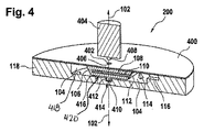
図2がカートリッジ200の別の実施例を示す。図2に示される実施例は、容器106が第1の流体リザーバ108および第2の流体リザーバ202を有することを除いて、図1に示される実施例に類似する。第1のリザーバ108が流体110で充填され、第2のリザーバ202が第2の流体204で充填される。いくつかの事例では、流体110および204が同じ流体であり、他の事例では、これらが異なる。この実施例では、流体リザーバ108、202の各々を個別に密閉する穿孔可能シール112が存在する。容器106を時計回りに回転させることにより、穿孔要素114が第1の流体リザーバ108を開ける。容器106を反時計回りに回転させることにより、第2の流体リザーバ202が開けられる。図1および図2に示される実施例の両方で、カートリッジ100、200が回転軸102を中心として比較的高い速度で回転させられ得、これにより流体110または204がダクト116を通るように移動させられる。図2の破線206が図4の断面図の位置を示す。
FIG. 2 shows another embodiment of the
図3が同じカートリッジ200の斜視図を示す。
図4が図2のカートリッジ200の斜視断面図を示す。図4は線206に沿う断面図を示している。カートリッジ200がキャリア構造118およびカバー400で形成されていることを見ることができる。この実施例では、回転アクチュエータ404を容器106に係合させるための孔402がカバー400内に存在する。容器106が第1の係合表面406を有し、回転アクチュエータ404が第2の係合表面408を有する。この実施例では、第2の係合表面408はカートリッジに食い込んで容器106に接触するピン状構造である。いくつかの実施例では、孔402がより大きくてもよく、いくつかの実施例では、孔402が、使用前に、オペレータによって取り外され得るシールによって覆われ得る。他の実施例では、シールが孔402を覆い、次いで、第2の係合表面408がシールを押して進んで容器106に接触することができる。
FIG. 3 shows the same perspective view of the
FIG. 4 shows a perspective sectional view of the
容器106が、キャリア構造118の中で短い距離で延在する小さいシャフト410を有する。これが、キャリア構造118の第2の摩擦要素414に接触する第1の摩擦要素412として使用され得る。例えば、シャフト410が圧入構造を有することができるか、または、軸102を中心として容器106を回転させようとするときに摩擦するような何らかの材料または表面を有することができる。別法としてまたは加えて、容器106とキャリア構造118との間のスペース416が、容器106の回転摩擦を増大させるのに使用される構造を有することができる。例えば、これらの表面のわずかな部分が粗面化されてよいか、または、カートリッジ200に対しての容器106の自由回転を阻害する構造を有することができる。
The
キャリア構造118がキャビティ104内に形成される第1の平坦表面418を有することを見ることができる。この表面は回転軸102に対して垂直である。容器106が回転軸102に対して垂直である第2の平坦表面420を有することを見ることができる。
It can be seen that the
代替形態として、回転軸に対して垂直ではない表面を有することも可能である。例えば、回転軸に平行であるかまたは回転軸を中心として円筒対称である表面により摩擦要素が得られてもよい。いくつかの実施例では、容器が、キャビティに接触することができる側壁または他の表面を有することができる。容器はまた、摩擦要素として機能するベアリングまたはブシュによって支持され得る。 As an alternative, it is also possible to have a surface which is not perpendicular to the rotation axis. For example, the friction element may be provided by a surface that is parallel to the axis of rotation or cylindrically symmetric about the axis of rotation. In some embodiments, the container can have a sidewall or other surface that can contact the cavity. The container may also be supported by bearings or bushings that function as friction elements.
摩擦要素を形成する表面の幾何形状も多様であってよい。このような表面の幾何形状は垂直の成分および平行な成分の両方を有することができる(例えば、45°の表面、または、凹形表面/凸形表面が使用され得る)。 The geometry of the surface forming the friction element may also vary. Such surface geometries can have both vertical and parallel components (eg, 45 ° surfaces or concave / convex surfaces can be used).
図5〜図11がカートリッジ200を使用する方法を示す。最初に図5に開始位置が示される。カートリッジ200および容器106が開始位置にある。回転アクチュエータ404は引き出されており、カートリッジ200に接触していない。カートリッジ200が回転させられる場合、容器106がディスクと共に同じ速度で回転する。
5-11 illustrate the method of using the
次いで、図6で、回転アクチュエータ404が方向600に移動されており、その結果、回転アクチュエータ404、表面406および408が互いに対合している。この特定の実施例では、これにより、回転アクチュエータ404に対しての容器106の位置が固定される。
Then, in FIG. 6, the
次いで、図7で、回転アクチュエータ404が容器106を固定位置で保持し、カートリッジ200が回転700に沿って時計回りに回転させられる。これにより穿孔要素114が流体リザーバ202のシール112を穿孔する。これにより流体204が漏出して中央キャビティ104の中に流れ込む。
Then, in FIG. 7, the
次いで、図8で、カートリッジ200が反時計回り方向800に逆に回転させられ、カートリッジ200の残りの部分に対する容器106の位置をその元の開始位置に戻す。
次いで、図9で、回転アクチュエータ404が方向900においてカートリッジから引き出される。回転アクチュエータ404が容器から離れるように移動すると、容器106が固定位置にいなくなる。カートリッジ200がさらに回転すると、容器106も同様に回転する。
Then, in FIG. 8, the
The
次いで、図10で、回転アクチュエータ404が引き出されている。次いで、カートリッジ200が回転させられ、キャリア構造118および容器106が同じ速度で一体に回転する。矢印1000が回転方向を示す。この回転により、流体204が、穿孔された流体リザーバ204から押し出されて中央キャビティ104の中に入る。さらに回転することで、流体204がダクト116を通過させられてカートリッジ200の流体構造の中に入る。
Then, in FIG. 10, the
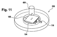
図11がカートリッジ200を示しており、ここでは、すべての流体がダクト116を通ってカートリッジ200の流体構造の中に入り、流体リザーバ204および中央キャビティ104の両方の流体が空になっている。
FIG. 11 shows the
図12がカートリッジ1200の代替的設計構成を示す。カートリッジ1200の設計構成は図1に示されるカートリッジ100の設計構成に類似するが、この実施例では、容器106が、表面1202および1204上にそれぞれ位置する両方の端部のところに穿孔可能シール112を有する。各穿孔可能シール112の近くに位置する穿孔要素114が存在する。この特定の設計構成は、2つの端部のところで流体リザーバ108が開けられるという利点を有することができる。これにより、流体リザーバ108の通気を向上させることができ、および/または、流体リザーバ108からの排水をより迅速にすることができる。
FIG. 12 shows an alternative design configuration of the
図13が図2に示されるカートリッジ200に類似するカートリッジ1300を示す。しかし、この実施例では、反対側の表面1202および1204において、容器106の側面の両端部上に穿孔可能シール112が存在する。軸102を中心としてキャリア構造118に対して容器106を時計回りに回転させることにより、第1の流体リザーバ108および第2の流体リザーバ202の両方の穿孔可能シール112が同時に穿孔される。これは、第1の流体110および第2の流体204が中央キャビティ104内で混合され得るという利点を有することができる。別法として、リザーバが順番に開けられてもよく、その場合、1つの流体が最初に解放されて、次のステップで二番目の流体が解放される。
FIG. 13 shows a
図14が図13に示されるカートリッジ1300の断面図を示す。この図はカートリッジ200の上の図に類似する。
図15がカートリッジ1500の一部分を示す。この実施例では、キャビティ104’を備えるキャリア構造のわずかな区間のみが示される。この実施例では、キャビティ104’が回転軸102から外れる。容器106は、キャビティ104’内で摺動するが回転軸102の周りを回転するように設計されている。この実施例では、容器106が回転軸102の周りで時計回りまたは反時計回りのどちらにも回転させられ得る。個別に開けられ得る2つの異なる流体リザーバ108、202が存在する。
FIG. 14 shows a cross-sectional view of the
FIG. 15 shows a portion of the
図16では、キャビティ104’を示すカートリッジの同じ部分1500が再び示されている。この事例では、容器106が、回転軸102の周りでカートリッジ1500に対して回転方向1600に沿って時計回りに回転させられている。穿孔要素114が穿孔可能シール112を開けていることから、第1の流体リザーバ108が開けられている。
In FIG. 16, the
図17は、容器106が回転軸102を中心としてカートリッジ1500に対して方向1700に反時計回りに回転させられていることを除いて、図16に類似する。この実施例では、代わりに、第2の流体リザーバ202が開けられている。
FIG. 17 is similar to FIG. 16 except that the
図18が、キャビティ104’を示しているカートリッジ1800の一部分を示している。図18に示される実施例は、容器106の設計構成が異なることを除いて、図15に示される実施例に類似する。この実施例では、穿孔可能シール112が容器106の下方を延在する。容器106が回転軸を中心としてカートリッジ1800に対して回転させられると、穿孔可能シール112が穿孔要素114によって穿孔されるかまたは裂かれる。
FIG. 18 shows a portion of the
図19が、キャビティ104’を示しているカートリッジ1900の一部分の別の実施例を示す。図19に示される実施例は、穿孔可能シール112が端部ではなく容器106の角部にあることを除いて、図15に示される実施例に類似する。回転軸を中心としてカートリッジ1900に対して容器106を回転させることで、流体リザーバ108、202がやはり開けられる。
FIG. 19 shows another embodiment of a portion of
図20が、軸から外れる容器106を備えるカートリッジの異なる実施例を示している。図20は、キャビティ104’を示しているカートリッジ2000の一部分を示している。これは、図15〜図19に示されるような上面図ではなく、断面図である。容器106が回転軸を中心として回転させられ得、2002を付される方向のどちらにもカートリッジ2000に対して中央で移動させられ得る。カートリッジを方向2002のいずれかに移動させることにより、穿孔要素114が穿孔可能シール112を裂いて開ける。
FIG. 20 shows a different embodiment of the cartridge with the
図21が、図15に示される容器106およびキャビティ104’の構造1500を組み込むカートリッジ2100の実施例を示す。
図21は、カートリッジ2100すなわち試験要素の2つの実施形態の概略図を示している。試験要素2100が基板またはキャリア構造118を有するハウジング2115を備える。基板118に加えて、ディスク形状の試験要素2100は、通常、カバー層(明確性のため、図示していない)をさらに含む。カバー層は基本的には流体構造を担持することもできるが、通常は、液体を送達するための開口部または通気開口部のみを有する。中央孔またはシャフトが設けられ得、その周りで試験要素が回転する。回転軸102は一実施形態では試験要素の内部に配置され、または、別の実施形態では試験要素の外側に配置される。
FIG. 21 shows an example of a
FIG. 21 shows a schematic of two embodiments of a
試験要素2100のハウジング2115が流体構造またはマイクロ流体構造さらにはクロマトグラフィ構造を有する。具体的には全血である試料液体が試料供給開口部2112を介して試験要素2100に送達される。試料分析チャンネル2116が、その流れ方向において、その始まりのところにある試料供給開口部2112と、その終わりのところにある測定ゾーン2119とを備える。チャンネルセクション2117が試料供給開口部2112と測定ゾーン2119との間を延在し、チャンネルセクション2117を通って液体試料が所定の流れ方向で測定ゾーン2119まで流れる。試験要素2100内での液体の輸送は毛管力および/または遠心力によって行われる。
The
液体試料の流れおよび/または流れ速度は試料分析チャンネル2116の流体構造を適切に選択することによって左右され得る。例えば、一実施形態では、チャンネルセクション2117、2118、2121の寸法は、毛管力の発生を促進するように選択される。別の実施形態では、チャンネルセクションの表面が親水性化される。また、試料分析チャンネル2116の個別のチャンネルセクションでのさらなる流れまたは充填は、例えば一実施形態では遠心力である、外力を作用させた後でのみ可能となり得る。
The flow and / or flow rate of the liquid sample may be governed by appropriate selection of the fluidic structure of the
さらに他の実施形態では、試料分析チャンネル2116の異なるセクションが異なる形で寸法決定されおよび/または異なる機能を有するように設けられる。例えば、一実施形態では、一次チャンネルセクション2118が体液試料と反応する試薬系を含むことができ、一実施形態では、その試薬系の少なくとも1つの試薬が乾燥形態または凍結乾燥形態で提供される。また、別の実施形態では、容器106の流体リザーバ108または202により試験要素2100に供給される少なくとも1つの試薬が液体形態で提供されることが可能である。
In still other embodiments, different sections of the
チャンネルセクション2117が、一次チャンネルセクション2118、毛細管ストップ2120、および、二次チャンネルセクション2121を備える。毛細管ストップ2120は一実施形態では幾何学的バルブとして実装され、または、別の実施形態では疎水性バリアとして実装される。毛細管ストップ2120に隣接する二次チャンネルセクション2121が、毛細管ストップ2120によって測り分けられる分の試料量を誘導する。毛細管ストップ2120を通って流れる量は、試験要素2100の回転速度を利用して、遠心力によって制御される。
適切な回転速度において、赤血球または他の細胞質の試料成分の分離が二次チャンネルセクション2121内で開始される。チャンネルセクション2118内に存在する試薬系に試薬が含まれ得、この試薬は一実施形態では乾燥形態で提供され得るものであり、二次チャンネルセクション2121の中に試料液体が入るときには既に溶解している。試料−試薬混合物の成分が、チャンバとして実装される収集ゾーン2122(血漿収集ゾーン)および収集ゾーン2123(赤血球収集ゾーン)で捕捉される。
Separation of red blood cell or other cytoplasmic sample components is initiated in the
収集ゾーン2122に隣接する測定ゾーンまたは測定構造2119が、一実施形態では、測定チャンバ2124を有し、この測定チャンバ2124が一実施形態では多孔質の吸収性マトリックスを含む。廃棄物チャンバ2125が流れ方向において測定チャンバ2124の後方に配置される。一実施形態では、測定チャンバ2124を通って流れた後、反応関与物(reaction participant)、試料成分および/または試薬成分が廃棄物チャンバ2125内に廃棄される。
The measurement zone or
廃棄物チャンバ2125は、一実施形態では、測定ゾーン2119を通って流れてきた液体を受け取るような形で、測定ゾーン2119に対しての流体接続部を有する。
加えて、洗浄液供給源が容器106によって提供される。洗浄液チャンネルまたはダクト2126がキャビティ104’に隣接する。洗浄液チャンネル2126が、一実施形態では、その端部のところで測定ゾーン2119に流体連通され、その結果、洗浄液が洗浄液チャンネル2126を通して測定チャンバ2124の中へと吸引される。測定チャンバ2124のマトリックスが洗浄され、阻害するような余分な反応関与物がすべて除去される。次いで、洗浄液がやはり廃棄物チャンバ2125に到達する。
The
In addition, a cleaning fluid source is provided by the
図22が自動分析器の実施例を示す。自動分析器2200がカートリッジ200を受けるように適合される。回転軸102を中心としてカートリッジ200を回転させるように動作可能であるカートリッジスピナ2202が存在する。カートリッジスピナ2202が、カートリッジ2208の一部分に取り付けられるグリッパ2206に取り付けられるモータ2204を有する。カートリッジ200は、さらに、測定構造または透明構造2210を有するものとして示されている。カートリッジ200は測定システム2212の前方まで測定構造2210を移動させるように回転させられ得、測定システム2212が処理済み生体試料に対して例えば光学測定を実施することができる。上で示した回転アクチュエータ404がこの図にも示される。回転アクチュエータ404はカートリッジ200内の1つまたは複数の流体リザーバを開けるのに使用され得る。アクチュエータ404、カートリッジスピナ2202および測定システム2212は、すべて、制御装置2214のハードウェアインターフェース2216に接続されて示されている。制御装置2214が、ハードウェアインターフェース2216と、電子記憶装置2220と、電子メモリ222と、ネットワークインターフェース2224とに繋がるプロセッサ2218を含む。電子メモリ2222が、プロセッサ2218により自動分析器2200の動作および機能を制御するのを可能にする機械実行可能命令2230を有する。電子記憶装置2220は、プロセッサ2218により命令2230が実行されたときに得られた測定2232を含むものとして示されている。ネットワークインターフェース2224が、プロセッサ2218によりネットワークインターフェース2226を介してラボラトリ情報システム2228に測定2232を送信するのを可能にする。
FIG. 22 shows an embodiment of an automatic analyzer. An
図23が、図22の自動分析器2200を動作させる方法を示すフローチャートを示す。最初に、ステップ2300で、生体試料がカートリッジ200の流体構造の中に配置される。これは手動で行われてよく、あるいは、存在する場合には、生体試料をカートリッジ200に入れるための計量分配またはピペット操作を行うための自動システムによって行われてもよい。次に、ステップ2302で、キャビティと少なくとも1つの容器との間の摩擦に打ち勝ち、カートリッジ200の回転軸102の周りでカートリッジに対して少なくとも1つの容器を回転させて、穿孔可能シールが開けられるように、回転アクチュエータ404を使用して少なくとも1つの容器に対してトルクが加えられる。カートリッジに対する少なくとも1つの容器の回転により、少なくとも1つの穿孔構造が穿孔可能シールを穿孔することによりシールが開けられる。例えば、図22に示される実施例では、アクチュエータ404がモータ組立体2202から分離されている。モータ2204がカートリッジ200を回転させる間、アクチュエータ404が容器を固定した状態で保持するのに使用され得る。次いで、ステップ2304で、プロセッサ2218が、流体構造を使用して生体試料を処理して処理済み生体試料とするためにカートリッジの回転速度を制御する。次いで、ステップ2306で、少なくとも1つの流体がダクトおよび流体構造の少なくとも一部分を通過させられるために、プロセッサがカートリッジの回転速度を制御する。キャビティと少なくとも1つの容器との間の摩擦により、少なくとも1つの容器がカートリッジと同じ速度で回転軸の周りを回転する。最後に、ステップ2308で、測定システム2212を使用する測定構造2210を使用して測定2232が実施される。ステップ2302、2304、2306は異なる順序で実施されてもよいし、複数回実施されてもよい。
FIG. 23 shows a flow chart illustrating a method of operating the
100 カートリッジ
102 回転軸
104 中央キャビティ
104’ キャビティ
106 容器
108 流体リザーバ
110 流体
112 穿孔可能シール
114 穿孔要素
116 ダクト
118 キャリア構造
120 流体構造のためのスペース
200 カートリッジ
202 第2の流体リザーバ
204 第2の流体
206 断面線
400 カバー
402 開口部
404 回転アクチュエータ
406 第1の係合表面
408 第2の係合表面
410 シャフト
412 第1の摩擦要素
414 第2の摩擦要素
416 容器とキャリア構造との間のスペース
418 第1の平坦表面
420 第2の平坦表面
600 方向
700 時計回り回転
800 反時計回り回転
900 方向
1000 回転方向
1200 カートリッジ
1202 容器の表面
1204 容器の表面
1300 カートリッジ
1500 キャビティ104’を示すカートリッジの部分
1600 反時計回り回転
1800 キャビティ104’を示すカートリッジの部分
1900 キャビティ104’を示すカートリッジの部分
2000 キャビティ104’を示すカートリッジの部分
2002 回転方向
2113 フラッシング液供給開口部
2115 ハウジング
2116 試料分析チャンネル
2117 チャンネルセクション
2118 一次チャンネルセクション
2119 測定ゾーンまたは測定構造
2120 毛細管ストップ
2121 二次チャンネルセクション
2122 血漿収集ゾーン
2123 赤血球収集ゾーン
2124 測定チャンバ
2125 廃棄物チャンバ
2130 プライミング構造
2131 フラッシング液収集チャンバ
2132 フラッシング液チャンネル
2133 バルブ
2134 通気チャンネル
2135 通気開口部
2200 自動分析器
2202 カートリッジスピナ
2204 モータ
2206 グリッパ
2208 カートリッジの一部分
2210 測定構造
2212 測定システム
2214 制御装置
2216 ハードウェアインターフェース
2218 プロセッサ
2220 電子記憶装置
2222 電子メモリ
2224 ネットワークインターフェース
2226 ネットワーク接続部
2228 ラボラトリ情報システム
2230 実行可能命令
2232 測定
2300 生体試料を流体構造の中に配置するステップ
2302 キャビティと少なくとも1つの容器との間の摩擦に打ち勝ち、カートリッジの回転軸の周りでカートリッジに対して少なくとも1つの容器を回転させて、穿孔可能シールを開けることを目的として、回転アクチュエータを使用して少なくとも1つの容器にトルクを加えるステップ
2304 流体構造を使用して生体試料を処理して処理済み生体試料とするように、カートリッジの回転速度を制御するステップ
2306 少なくとも1つの流体がダクトおよび流体構造の少なくとも一部分を通過させられるように、カートリッジの回転速度を制御するステップ
2308 測定システムを使用して、測定構造を介して測定を実施するステップ
Reference Signs List 100 cartridge 102 rotation shaft 104 central cavity 104 'cavity 106 container 108 fluid reservoir 110 fluid 112 pierceable seal 114 piercing element 116 duct 118 carrier structure 120 space for fluid structure 200 cartridge 202 second fluid reservoir 204 second fluid 206 section line 400 cover 402 opening 404 rotary actuator 406 first engagement surface 408 second engagement surface 410 shaft 412 first friction element 414 second friction element 416 space between container and carrier structure 418 First flat surface 420 second flat surface 600 direction 700 clockwise rotation 800 counterclockwise rotation 900 direction 1000 rotation direction 1200 cartridge 1202 container surface 1204 container surface 1300 cartridge 1500 part of the cartridge showing the cavity 104 'counter clockwise rotation 1800 part of the cartridge showing the cavity 104' 1900 part of the cartridge showing the cavity 104 '2000 part of the cartridge showing the cavity 104' 2002 rotation direction 2113 flushing fluid supply Opening 2115 Housing 2116 Sample Analysis Channel 2117 Channel Section 2118 Primary Channel Section 2119 Measurement Zone or Structure 2120 Capillary Stop 2121 Secondary Channel Section 2122 Plasma Collection Zone 2123 Red Blood Cell Collection Zone 2124 Measurement Chamber 2125 Waste Chamber 2130 Priming Structure 2131 Flushing Fluid Collection chamber 2132 flush Fluid channels 2133 valves 2134 vent channels 2135 vent openings 2200 autoanalyzer 2202 cartridge spinners 2204 motors 2206 grippers 2208 cartridge parts 2210 measuring structure 2212 measuring system 2214 control device 2216 hardware interface 2218 processor 2220 electronic storage 2222 electronic memory 2224 Network interface 2226 Network connection 2228 Laboratory information system 2230 Executable instructions 2232 Measurement 2300 Placing the biological sample in the fluid structure 2302 Overcoming the friction between the cavity and the at least one container, around the rotation axis of the cartridge Rotate at least one container relative to the cartridge Torque the at least one container using a rotary actuator for the purpose of opening the seal 2304. Rotating speed of the cartridge so that the biological sample is processed into a processed biological sample using a fluidic structure Controlling the speed of rotation of the cartridge such that at least one fluid is allowed to pass through the duct and at least a portion of the
Claims (26)
前記カートリッジが回転軸(102)の周りで回転するように動作可能であり、
前記カートリッジが、少なくとも1つの流体(110、204)を含む少なくとも1つの流体リザーバ(108、202)を備える少なくとも1つの容器(106)をさらに備え、
前記カートリッジが前記少なくとも1つの容器の各々のためのキャビティ(104、104’)を備え、
前記少なくとも1つのキャビティが前記キャリア構造と前記カバーから形成され、
前記少なくとも1つの容器が前記キャビティ内で前記カートリッジの前記回転軸を中心として回転するように構成され、
前記少なくとも1つの容器が前記カートリッジに対して回転するように構成され、
前記少なくとも1つの流体リザーバの各々が穿孔可能シール(112)を備え、
前記キャビティが前記少なくとも1つの流体リザーバの各々のための少なくとも1つの穿孔構造(114)を備え、
前記少なくとも1つの穿孔構造が、前記カートリッジに対して前記少なくとも1つの容器が回転させられるときに前記穿孔可能シールを穿孔することにより前記シールを開けるように構成され、
前記少なくとも1つの容器が第1の摩擦要素(412)を備え、前記キャビティが第2の摩擦要素(414)を備え、
前記第1の摩擦要素が前記第2の摩擦要素に対合し、
前記第1の摩擦要素および前記第2の摩擦要素が、前記キャビティと前記少なくとも1つの容器との間で摩擦を起こすように構成され、
前記少なくとも1つの容器が、前記少なくとも1つの容器にトルクを加えるように動作可能である回転アクチュエータ(404)の第2の係合表面(408)に対合するように動作可能である第1の係合表面(406)を備え、
前記カートリッジが、生体試料を処理して処理済み生体試料とするための流体構造(120、2116、2117、2118、2120、2121、2122、2123、2124、2125、2130、2131、2132、2133、2134、2135)を備え、
前記流体構造が前記キャリア構造および前記カバーから形成され、
前記カートリッジが前記キャビティと前記流体構造との間にダクト(116)を備え、
前記ダクトが前記キャリア構造および前記カバーから形成され、
前記流体構造が前記キャリア構造内に位置し、
前記流体構造が前記処理済み生体試料の測定を可能にするための測定構造(2119、2210)を備え、
前記流体構造が前記生体試料を受け取るように構成され、
前記方法が、
前記生体試料を前記流体構造の中に配置するステップ(2300)と、
前記キャビティと前記少なくとも1つの容器との間の摩擦に打ち勝ち、前記カートリッジの前記回転軸の周りで前記カートリッジに対して前記少なくとも1つの容器を回転させて、前記穿孔可能シールを開けることを目的として、前記回転アクチュエータを使用して前記少なくとも1つの容器にトルクを加えるステップ(2302)であって、前記カートリッジに対して前記少なくとも1つの容器を回転させることにより、前記少なくとも1つの穿孔構造が前記穿孔可能シールを穿孔することにより前記シールが開けられる、ステップ(2302)と、
前記流体構造を使用して前記生体試料を処理して前記処理済み生体試料とするように、前記カートリッジの回転速度を制御するステップ(2304)と、
少なくとも1つの流体が前記ダクトおよび前記流体構造の少なくとも一部分を通過させられるように、前記カートリッジの回転速度を制御するステップ(2306)であって、前記キャビティと前記少なくとも1つの容器との間の摩擦により、前記少なくとも1つの容器が前記カートリッジと同じ速度で前記カートリッジの前記回転軸の周りで回転する、ステップ(2306)と、
測定システムを使用して、前記測定構造を介して測定を実施するステップ(2308)と、
を含む方法。 A method of performing a processed biological treatment measurement using a cartridge (100, 200, 2100) formed from a carrier structure (118) and a cover (400),
The cartridge is operable to rotate about an axis of rotation (102),
The cartridge further comprises at least one container (106) comprising at least one fluid reservoir (108, 202) comprising at least one fluid (110, 204),
The cartridge comprises a cavity (104, 104 ') for each of the at least one container,
The at least one cavity is formed from the carrier structure and the cover;
The at least one container is configured to rotate within the cavity about the rotational axis of the cartridge;
The at least one container is configured to rotate relative to the cartridge;
Each of the at least one fluid reservoir comprises a pierceable seal (112);
The cavity comprises at least one drilling structure (114) for each of the at least one fluid reservoir;
The at least one piercing structure is configured to open the seal by piercing the pierceable seal when the at least one container is rotated relative to the cartridge;
The at least one container comprises a first friction element (412) and the cavity comprises a second friction element (414);
The first friction element faces the second friction element;
The first friction element and the second friction element are configured to cause friction between the cavity and the at least one container,
A first at least one container is operable to mate with a second engagement surface (408) of a rotary actuator (404) operable to apply torque to the at least one container. With an engagement surface (406)
The cartridge is a fluid structure (120, 2116, 2117, 2118, 2120, 2121, 1222, 2123, 2124, 2125, 2130, 2131, 2132, 2133, 2134) for processing the biological sample into a processed biological sample. , 2135),
The fluidic structure is formed from the carrier structure and the cover,
The cartridge comprises a duct (116) between the cavity and the fluid structure;
The duct is formed from the carrier structure and the cover;
The fluidic structure is located within the carrier structure;
The fluidic structure comprises a measuring structure (2119, 2210) for enabling measurement of the processed biological sample;
The fluid structure is configured to receive the biological sample;
The above method is
Placing the biological sample in the fluid structure (2300);
To overcome the friction between the cavity and the at least one container and to rotate the at least one container relative to the cartridge about the rotational axis of the cartridge to open the pierceable seal Applying a torque (2302) to the at least one container using the rotary actuator, wherein the at least one drilling structure is perforated by rotating the at least one container relative to the cartridge Drilling (2302) the seal by drilling the seal.
Controlling the rotational speed of the cartridge (2304) to process the biological sample into the processed biological sample using the fluidic structure;
Controlling the rotational speed of the cartridge (2306) such that at least one fluid is allowed to pass through the duct and at least a portion of the fluid structure, friction between the cavity and the at least one container Causing the at least one container to rotate about the axis of rotation of the cartridge at the same speed as the cartridge ;
Performing a measurement via the measurement structure using a measurement system (2308);
Method including.
前記カートリッジがキャリア構造(118)およびカバー(400)から形成され、
前記カートリッジが回転軸(102)の周りで回転するように動作可能であり、
前記カートリッジが、少なくとも1つの流体(110、204)を含む少なくとも1つの流体リザーバ(108、202)を備える少なくとも1つの容器(106)をさらに備え、
前記カートリッジが前記少なくとも1つの容器の各々のためのキャビティ(104、104’)を備え、
前記少なくとも1つのキャビティが前記キャリア構造と前記カバーから形成され、
前記少なくとも1つの容器が前記キャビティ内で前記カートリッジの前記回転軸を中心として回転するように構成され、
前記少なくとも1つの容器が前記カートリッジに対して回転するように構成され、
前記少なくとも1つの流体リザーバの各々が穿孔可能シール(112)を備え、
前記キャビティが前記少なくとも1つの流体リザーバの各々のための少なくとも1つの穿孔構造(114)を備え、
前記少なくとも1つの穿孔構造が、前記カートリッジに対して前記少なくとも1つの容器が回転させられるときに前記穿孔可能シールを穿孔することにより前記シールを開けるように構成され、
前記少なくとも1つの容器が第1の摩擦要素(412)を備え、前記キャビティが第2の摩擦要素(414)を備え、
前記第1の摩擦要素が前記第2の摩擦要素に対合し、
前記第1の摩擦要素および前記第2の摩擦要素が、前記キャビティと前記少なくとも1つの容器との間で摩擦を起こすように構成され、
前記少なくとも1つの容器が、前記少なくとも1つの容器にトルクを加えるように動作可能である回転アクチュエータの第2の係合表面(408)に対合するように動作可能である第1の係合表面(406)を備え、
前記カートリッジが、生体試料を処理して処理済み生体試料とするための流体構造(120、2116、2117、2118、2120、2121、2122、2123、2124、2125、2130、2131、2132、2133、2134、2135)を備え、
前記流体構造が前記キャリア構造および前記カバーから形成され、
前記流体構造が前記キャリア構造内に位置し、
前記カートリッジが前記キャビティと前記流体構造との間にダクト(116)を備え、
前記ダクトが前記キャリア構造および前記カバーの中に形成され、
前記流体構造が前記処理済み生体試料の測定を可能にするための測定構造(2119、2210)を備え、
前記流体構造が前記生体試料を受け取るように構成される、カートリッジ(100、200、2100)。 A cartridge (100, 200, 2100) for an automatic analyzer (2200), wherein
The cartridge is formed from a carrier structure (118) and a cover (400).
The cartridge is operable to rotate about an axis of rotation (102),
The cartridge further comprises at least one container (106) comprising at least one fluid reservoir (108, 202) comprising at least one fluid (110, 204),
The cartridge comprises a cavity (104, 104 ') for each of the at least one container ,
The at least one cavity is formed from the carrier structure and the cover;
The at least one container is configured to rotate within the cavity about the rotational axis of the cartridge;
The at least one container is configured to rotate relative to the cartridge;
Each of the at least one fluid reservoir comprises a pierceable seal (112);
The cavity comprises at least one drilling structure (114) for each of the at least one fluid reservoir;
The at least one piercing structure is configured to open the seal by piercing the pierceable seal when the at least one container is rotated relative to the cartridge;
The at least one container comprises a first friction element (412) and the cavity comprises a second friction element (414);
The first friction element faces the second friction element;
The first friction element and the second friction element are configured to cause friction between the cavity and the at least one container,
A first engagement surface operable to mate with a second engagement surface (408) of a rotary actuator operable to apply torque to the at least one container. Equipped with (406)
The cartridge is a fluid structure (120, 2116, 2117, 2118, 2120, 2121, 1222, 2123, 2124, 2125, 2130, 2131, 2132, 2133, 2134) for processing the biological sample into a processed biological sample. , 2135),
The fluidic structure is formed from the carrier structure and the cover,
The fluidic structure is located within the carrier structure;
The cartridge comprises a duct (116) between the cavity and the fluid structure;
The duct is formed in the carrier structure and the cover;
The fluidic structure comprises a measuring structure ( 2119 , 2210) for enabling measurement of the processed biological sample;
A cartridge (100, 200, 2100), wherein the fluid structure is configured to receive the biological sample.
前記複数の流体リザーバの各々のための前記穿孔可能シールが前記複数の表面のうちの2つ以上の表面上に分布される、請求項3または4に記載のカートリッジ。 The at least one container comprises a plurality of surfaces (1202, 1204);
5. The cartridge of claim 3 or 4, wherein the pierceable seal for each of the plurality of fluid reservoirs is distributed on two or more of the plurality of surfaces.
前記回転軸が前記中央に位置する容器を通過する、請求項2から6までのいずれか一項に記載のカートリッジ。 One of the at least one container is a centrally located container (104);
The cartridge according to any one of claims 2 to 6, wherein the rotation axis passes through the centrally located container.
前記少なくとも1つの容器のうちの前記1つまたは複数の容器が前記キャビティ内で摺動することにより前記カートリッジの前記回転軸を中心として回転するように構成される、請求項2から7までのいずれか一項に記載のカートリッジ。 One or more of the at least one container is configured to slide within the cavity;
8. Any one of claims 2 to 7, wherein the one or more containers of the at least one container are configured to rotate about the rotational axis of the cartridge by sliding within the cavity. The cartridge according to claim 1.
前記ディスク状部分が円形プロファイルを有し、
前記円形プロファイルが中心を有し、
前記回転軸が前記中心を通過する、請求項2から8までのいずれか一項に記載のカートリッジ。 Said carrier structure comprises a disc-like portion,
The disc-like portion has a circular profile,
Said circular profile has a center,
9. A cartridge according to any one of the claims 2 to 8, wherein the axis of rotation passes through the center.
前記少なくとも1つの容器が前記開口部を通って前記カートリッジに対して回転可能に作動するように動作可能であり、
前記開口部が前記第1の係合表面を露出し、
前記第1の係合表面および前記第2の係合表面が機械的に対合するように構成される、請求項9に記載のカートリッジ。 The cartridge comprises an opening (402);
The at least one container is operable to rotatably move relative to the cartridge through the opening;
The opening exposes the first engagement surface;
The cartridge of claim 9, wherein the first engagement surface and the second engagement surface are configured to mechanically mate.
前記容器が第2の平坦表面(420)を有する、請求項2から17までのいずれか一項に記載のカートリッジ。 The cavity has a first flat surface,
A cartridge according to any of claims 2 to 17, wherein the container has a second flat surface (420).
前記第2の摩擦要素が前記第2の平坦表面上に形成され、
前記第1の摩擦要素および前記第2の摩擦要素が、前記回転軸を中心として前記少なくとも1つの容器が回転させられるときに、接触した状態を維持するように構成される、請求項18に記載のカートリッジ。 The first friction element is formed on the first flat surface,
The second friction element is formed on the second flat surface,
19. The apparatus of claim 18, wherein the first friction element and the second friction element are configured to maintain contact when the at least one container is rotated about the rotational axis. Cartridge.
前記第2の平坦表面が前記回転軸に対して垂直である、請求項18または19に記載のカートリッジ。 Said first flat surface being perpendicular to said axis of rotation;
20. A cartridge according to claim 18 or 19, wherein the second flat surface is perpendicular to the axis of rotation.
前記側壁が前記穿孔可能シールを備える、請求項2から23までのいずれか一項に記載のカートリッジ。 The at least one container comprises a side wall;
24. A cartridge according to any one of claims 2 to 23, wherein the side wall comprises the pierceable seal.
前記自動分析器が、カートリッジスピナ(2202)と、回転アクチュエータ(404)と、測定システム(2212)と、前記自動分析器を制御するように構成される制御装置(2214)とを備え、前記制御装置が
前記回転アクチュエータを使用して穿孔可能シールを開けることを目的として前記カートッジに対して少なくとも1つの容器を回転させるように(2302)、
前記カートリッジスピナを制御することにより流体構造を使用して生体試料を処理して処理済み生体試料とすることを目的として前記カートリッジの回転速度を制御するように(2304)、
少なくとも1つの流体がダクトをおよび前記流体構造の少なくとも一部分を通過させられることを目的として前記カートリッジの前記回転速度を制御するように(2306)、および
測定構造および前記測定システムを使用して測定を実施するように(2308)
構成される、
自動分析器。 26. An automatic analyzer configured to receive the cartridge according to any one of claims 2-25, wherein
The autoanalyzer comprises a cartridge spinner (2202), a rotary actuator (404), a measurement system (2212), and a controller (2214) configured to control the autoanalyzer, the control The apparatus rotates (2302) at least one container relative to the cartridge for the purpose of opening a pierceable seal using the rotary actuator.
Controlling the rotational speed of the cartridge for the purpose of processing the biological sample into a processed biological sample using a fluidic structure by controlling the cartridge spinner (2304);
(2306) to control the rotational speed of the cartridge for the purpose of allowing at least one fluid to pass through the duct and at least a part of the fluidic structure, and using the measurement structure and the measurement system As implemented (2308)
Configured,
Automatic analyzer.
Applications Claiming Priority (3)
| Application Number | Priority Date | Filing Date | Title |
|---|---|---|---|
| EP14168042.1A EP2944965A1 (en) | 2014-05-13 | 2014-05-13 | Rotatable cartridge for measuring a property of a biological sample |
| EP14168042.1 | 2014-05-13 | ||
| PCT/EP2015/060013 WO2015173097A1 (en) | 2014-05-13 | 2015-05-07 | Rotatable cartridge for measuring a property of a biological sample |
Publications (3)
| Publication Number | Publication Date |
|---|---|
| JP2017516086A JP2017516086A (en) | 2017-06-15 |
| JP2017516086A5 JP2017516086A5 (en) | 2018-06-21 |
| JP6549151B2 true JP6549151B2 (en) | 2019-07-24 |
Family
ID=50735885
Family Applications (1)
| Application Number | Title | Priority Date | Filing Date |
|---|---|---|---|
| JP2016562788A Active JP6549151B2 (en) | 2014-05-13 | 2015-05-07 | Rotatable cartridge for measuring properties of biological samples |
Country Status (6)
| Country | Link |
|---|---|
| US (1) | US9808801B2 (en) |
| EP (2) | EP2944965A1 (en) |
| JP (1) | JP6549151B2 (en) |
| KR (1) | KR101869184B1 (en) |
| CN (1) | CN107076768B (en) |
| WO (1) | WO2015173097A1 (en) |
Families Citing this family (10)
| Publication number | Priority date | Publication date | Assignee | Title |
|---|---|---|---|---|
| EP3173149A1 (en) | 2015-11-26 | 2017-05-31 | Roche Diagnostics GmbH | Determining a quantity of an analyte in a blood sample |
| WO2018043779A1 (en) * | 2016-09-05 | 2018-03-08 | 주식회사 녹십자엠에스 | Integrated cassette for measuring glycated hemoglobin |
| US10137447B1 (en) * | 2017-05-17 | 2018-11-27 | Biotix, Inc. | Ergonomic fluid handling tubes |
| WO2020041549A1 (en) | 2018-08-24 | 2020-02-27 | Zoetis Services Llc | Microfluidic rotor device |
| MX2021002160A (en) * | 2018-08-24 | 2021-04-28 | Zoetis Services Llc | Microfluidic rotor device. |
| CN112654428B (en) | 2018-08-24 | 2023-02-21 | 硕腾服务有限责任公司 | Method for producing a microfluidic rotor device |
| WO2020041548A1 (en) | 2018-08-24 | 2020-02-27 | Zoetis Services Llc | Microfluidic rotor device |
| BR112021003169A2 (en) | 2018-08-24 | 2021-05-11 | Zoetis Services Llc | systems and methods for inspecting a microfluidic rotor device |
| CN109991392B (en) * | 2019-04-11 | 2021-07-30 | 中原工学院 | Three-petal vessel for geotechnical test liquid-plastic limit combined determination and test method |
| WO2023102427A1 (en) * | 2021-11-30 | 2023-06-08 | Gregor Diagnostics | Sample collection device and system |
Family Cites Families (17)
| Publication number | Priority date | Publication date | Assignee | Title |
|---|---|---|---|---|
| US4812294A (en) * | 1986-02-28 | 1989-03-14 | Automated Diagnostic Systems, Inc. | Specimen processing system |
| KR0182619B1 (en) * | 1990-06-15 | 1999-05-01 | 로버트 피. 블랙버언 | Embedded Assay Assembly and Apparatus |
| US6309875B1 (en) * | 2000-02-29 | 2001-10-30 | Agilent Technologies, Inc. | Apparatus for biomolecular array hybridization facilitated by agitation during centrifuging |
| KR100807931B1 (en) * | 2001-05-25 | 2008-02-28 | 가부시키가이샤 히타치세이사쿠쇼 | Apparatus for Purifying Nucleic Acid and Method of Purifying Nucleic Acid |
| US20040131500A1 (en) * | 2002-01-18 | 2004-07-08 | Chow Herbert S. | Device and method for evaluating platelets |
| US20030219890A1 (en) * | 2002-05-21 | 2003-11-27 | Gordon Gary B. | Probe array bio-analysis by centrifuging shallow reaction cell |
| US20050169804A1 (en) * | 2004-02-04 | 2005-08-04 | Hach Company | User-configurable analytical rotor system |
| JP2006308366A (en) * | 2005-04-27 | 2006-11-09 | Hitachi High-Technologies Corp | Chemical analyzer and chemical analysis cartridge |
| US20070065346A1 (en) * | 2005-09-19 | 2007-03-22 | Henry Lauren R | Micro-fluidic device with neutralization and neutralization methods |
| JP4901333B2 (en) * | 2006-06-30 | 2012-03-21 | ローム株式会社 | Microchip inspection device |
| EP1916524A1 (en) | 2006-09-27 | 2008-04-30 | Roche Diagnostics GmbH | Rotatable test element |
| KR20080107212A (en) * | 2007-06-05 | 2008-12-10 | 삼성전자주식회사 | Microfluidic apparatus with fluid container |
| ATE541639T1 (en) | 2007-11-24 | 2012-02-15 | Hoffmann La Roche | ANALYSIS SYSTEM AND METHOD FOR ANALYZING A BODY FLUID SAMPLE FOR AN ANALYTE CONTAINED THEREIN |
| US20110085950A1 (en) * | 2009-10-08 | 2011-04-14 | Samsung Electronics Co., Ltd. | Centrifugal force based microfluidic system and bio cartridge for the microfluidic system |
| CN103517763A (en) * | 2011-03-15 | 2014-01-15 | 卡柯洛塑料技术有限公司 | Surface preparation |
| EP2709761B1 (en) * | 2011-05-18 | 2019-08-14 | DiaSorin S.p.A. | Systems and methods for volumetric metering on a sample processing device |
| GB201216454D0 (en) * | 2012-09-14 | 2012-10-31 | Carclo Technical Plastics Ltd | Sample metering device |
-
2014
- 2014-05-13 EP EP14168042.1A patent/EP2944965A1/en not_active Withdrawn
-
2015
- 2015-05-07 JP JP2016562788A patent/JP6549151B2/en active Active
- 2015-05-07 EP EP15721222.6A patent/EP3143412B1/en active Active
- 2015-05-07 WO PCT/EP2015/060013 patent/WO2015173097A1/en active Application Filing
- 2015-05-07 CN CN201580023548.0A patent/CN107076768B/en active Active
- 2015-05-07 KR KR1020167030033A patent/KR101869184B1/en active IP Right Grant
-
2016
- 2016-11-04 US US15/343,389 patent/US9808801B2/en active Active
Also Published As
| Publication number | Publication date |
|---|---|
| CN107076768B (en) | 2018-11-30 |
| US20170050185A1 (en) | 2017-02-23 |
| US9808801B2 (en) | 2017-11-07 |
| EP3143412B1 (en) | 2019-12-18 |
| EP2944965A1 (en) | 2015-11-18 |
| CN107076768A (en) | 2017-08-18 |
| JP2017516086A (en) | 2017-06-15 |
| WO2015173097A1 (en) | 2015-11-19 |
| KR20160137633A (en) | 2016-11-30 |
| KR101869184B1 (en) | 2018-06-19 |
| EP3143412A1 (en) | 2017-03-22 |
Similar Documents
| Publication | Publication Date | Title |
|---|---|---|
| JP6549151B2 (en) | Rotatable cartridge for measuring properties of biological samples | |
| US10016758B2 (en) | Rotatable cartridge for analyzing a biological sample | |
| US10307757B2 (en) | Rotatable cartridge with a metering chamber for analyzing a biological sample | |
| JP7007799B2 (en) | Blood sampling device with capillary structure | |
| US11406979B2 (en) | Rotatable cartridge for processing and analyzing a biological sample and dispensing method therewith |
Legal Events
| Date | Code | Title | Description |
|---|---|---|---|
| A621 | Written request for application examination |
Free format text: JAPANESE INTERMEDIATE CODE: A621 Effective date: 20180424 |
|
| A521 | Request for written amendment filed |
Free format text: JAPANESE INTERMEDIATE CODE: A523 Effective date: 20180514 |
|
| A977 | Report on retrieval |
Free format text: JAPANESE INTERMEDIATE CODE: A971007 Effective date: 20190123 |
|
| A131 | Notification of reasons for refusal |
Free format text: JAPANESE INTERMEDIATE CODE: A131 Effective date: 20190225 |
|
| A521 | Request for written amendment filed |
Free format text: JAPANESE INTERMEDIATE CODE: A523 Effective date: 20190424 |
|
| TRDD | Decision of grant or rejection written | ||
| A01 | Written decision to grant a patent or to grant a registration (utility model) |
Free format text: JAPANESE INTERMEDIATE CODE: A01 Effective date: 20190604 |
|
| A61 | First payment of annual fees (during grant procedure) |
Free format text: JAPANESE INTERMEDIATE CODE: A61 Effective date: 20190626 |
|
| R150 | Certificate of patent or registration of utility model |
Ref document number: 6549151 Country of ref document: JP Free format text: JAPANESE INTERMEDIATE CODE: R150 |
|
| R250 | Receipt of annual fees |
Free format text: JAPANESE INTERMEDIATE CODE: R250 |
|
| R250 | Receipt of annual fees |
Free format text: JAPANESE INTERMEDIATE CODE: R250 |