CN103517763A - Surface preparation - Google Patents
Surface preparation Download PDFInfo
- Publication number
- CN103517763A CN103517763A CN201280022171.3A CN201280022171A CN103517763A CN 103517763 A CN103517763 A CN 103517763A CN 201280022171 A CN201280022171 A CN 201280022171A CN 103517763 A CN103517763 A CN 103517763A
- Authority
- CN
- China
- Prior art keywords
- fluid
- passage
- capillary channel
- capillary
- sample
- Prior art date
- Legal status (The legal status is an assumption and is not a legal conclusion. Google has not performed a legal analysis and makes no representation as to the accuracy of the status listed.)
- Pending
Links
Images


Classifications
-
- B—PERFORMING OPERATIONS; TRANSPORTING
- B01—PHYSICAL OR CHEMICAL PROCESSES OR APPARATUS IN GENERAL
- B01L—CHEMICAL OR PHYSICAL LABORATORY APPARATUS FOR GENERAL USE
- B01L3/00—Containers or dishes for laboratory use, e.g. laboratory glassware; Droppers
- B01L3/50—Containers for the purpose of retaining a material to be analysed, e.g. test tubes
- B01L3/502—Containers for the purpose of retaining a material to be analysed, e.g. test tubes with fluid transport, e.g. in multi-compartment structures
- B01L3/5027—Containers for the purpose of retaining a material to be analysed, e.g. test tubes with fluid transport, e.g. in multi-compartment structures by integrated microfluidic structures, i.e. dimensions of channels and chambers are such that surface tension forces are important, e.g. lab-on-a-chip
- B01L3/50273—Containers for the purpose of retaining a material to be analysed, e.g. test tubes with fluid transport, e.g. in multi-compartment structures by integrated microfluidic structures, i.e. dimensions of channels and chambers are such that surface tension forces are important, e.g. lab-on-a-chip characterised by the means or forces applied to move the fluids
-
- B—PERFORMING OPERATIONS; TRANSPORTING
- B01—PHYSICAL OR CHEMICAL PROCESSES OR APPARATUS IN GENERAL
- B01L—CHEMICAL OR PHYSICAL LABORATORY APPARATUS FOR GENERAL USE
- B01L3/00—Containers or dishes for laboratory use, e.g. laboratory glassware; Droppers
- B01L3/50—Containers for the purpose of retaining a material to be analysed, e.g. test tubes
- B01L3/502—Containers for the purpose of retaining a material to be analysed, e.g. test tubes with fluid transport, e.g. in multi-compartment structures
- B01L3/5027—Containers for the purpose of retaining a material to be analysed, e.g. test tubes with fluid transport, e.g. in multi-compartment structures by integrated microfluidic structures, i.e. dimensions of channels and chambers are such that surface tension forces are important, e.g. lab-on-a-chip
- B01L3/502707—Containers for the purpose of retaining a material to be analysed, e.g. test tubes with fluid transport, e.g. in multi-compartment structures by integrated microfluidic structures, i.e. dimensions of channels and chambers are such that surface tension forces are important, e.g. lab-on-a-chip characterised by the manufacture of the container or its components
-
- B—PERFORMING OPERATIONS; TRANSPORTING
- B01—PHYSICAL OR CHEMICAL PROCESSES OR APPARATUS IN GENERAL
- B01L—CHEMICAL OR PHYSICAL LABORATORY APPARATUS FOR GENERAL USE
- B01L3/00—Containers or dishes for laboratory use, e.g. laboratory glassware; Droppers
- B01L3/50—Containers for the purpose of retaining a material to be analysed, e.g. test tubes
- B01L3/502—Containers for the purpose of retaining a material to be analysed, e.g. test tubes with fluid transport, e.g. in multi-compartment structures
- B01L3/5027—Containers for the purpose of retaining a material to be analysed, e.g. test tubes with fluid transport, e.g. in multi-compartment structures by integrated microfluidic structures, i.e. dimensions of channels and chambers are such that surface tension forces are important, e.g. lab-on-a-chip
- B01L3/502738—Containers for the purpose of retaining a material to be analysed, e.g. test tubes with fluid transport, e.g. in multi-compartment structures by integrated microfluidic structures, i.e. dimensions of channels and chambers are such that surface tension forces are important, e.g. lab-on-a-chip characterised by integrated valves
-
- B—PERFORMING OPERATIONS; TRANSPORTING
- B01—PHYSICAL OR CHEMICAL PROCESSES OR APPARATUS IN GENERAL
- B01L—CHEMICAL OR PHYSICAL LABORATORY APPARATUS FOR GENERAL USE
- B01L3/00—Containers or dishes for laboratory use, e.g. laboratory glassware; Droppers
- B01L3/56—Labware specially adapted for transferring fluids
- B01L3/561—Tubes; Conduits
-
- B—PERFORMING OPERATIONS; TRANSPORTING
- B01—PHYSICAL OR CHEMICAL PROCESSES OR APPARATUS IN GENERAL
- B01L—CHEMICAL OR PHYSICAL LABORATORY APPARATUS FOR GENERAL USE
- B01L2200/00—Solutions for specific problems relating to chemical or physical laboratory apparatus
- B01L2200/06—Fluid handling related problems
- B01L2200/0689—Sealing
-
- B—PERFORMING OPERATIONS; TRANSPORTING
- B01—PHYSICAL OR CHEMICAL PROCESSES OR APPARATUS IN GENERAL
- B01L—CHEMICAL OR PHYSICAL LABORATORY APPARATUS FOR GENERAL USE
- B01L2200/00—Solutions for specific problems relating to chemical or physical laboratory apparatus
- B01L2200/16—Reagents, handling or storing thereof
-
- B—PERFORMING OPERATIONS; TRANSPORTING
- B01—PHYSICAL OR CHEMICAL PROCESSES OR APPARATUS IN GENERAL
- B01L—CHEMICAL OR PHYSICAL LABORATORY APPARATUS FOR GENERAL USE
- B01L2300/00—Additional constructional details
- B01L2300/04—Closures and closing means
- B01L2300/041—Connecting closures to device or container
- B01L2300/042—Caps; Plugs
-
- B—PERFORMING OPERATIONS; TRANSPORTING
- B01—PHYSICAL OR CHEMICAL PROCESSES OR APPARATUS IN GENERAL
- B01L—CHEMICAL OR PHYSICAL LABORATORY APPARATUS FOR GENERAL USE
- B01L2300/00—Additional constructional details
- B01L2300/06—Auxiliary integrated devices, integrated components
- B01L2300/0672—Integrated piercing tool
-
- B—PERFORMING OPERATIONS; TRANSPORTING
- B01—PHYSICAL OR CHEMICAL PROCESSES OR APPARATUS IN GENERAL
- B01L—CHEMICAL OR PHYSICAL LABORATORY APPARATUS FOR GENERAL USE
- B01L2300/00—Additional constructional details
- B01L2300/16—Surface properties and coatings
- B01L2300/161—Control and use of surface tension forces, e.g. hydrophobic, hydrophilic
-
- B—PERFORMING OPERATIONS; TRANSPORTING
- B01—PHYSICAL OR CHEMICAL PROCESSES OR APPARATUS IN GENERAL
- B01L—CHEMICAL OR PHYSICAL LABORATORY APPARATUS FOR GENERAL USE
- B01L2400/00—Moving or stopping fluids
- B01L2400/04—Moving fluids with specific forces or mechanical means
- B01L2400/0403—Moving fluids with specific forces or mechanical means specific forces
- B01L2400/0406—Moving fluids with specific forces or mechanical means specific forces capillary forces
-
- B—PERFORMING OPERATIONS; TRANSPORTING
- B01—PHYSICAL OR CHEMICAL PROCESSES OR APPARATUS IN GENERAL
- B01L—CHEMICAL OR PHYSICAL LABORATORY APPARATUS FOR GENERAL USE
- B01L2400/00—Moving or stopping fluids
- B01L2400/04—Moving fluids with specific forces or mechanical means
- B01L2400/0475—Moving fluids with specific forces or mechanical means specific mechanical means and fluid pressure
- B01L2400/0487—Moving fluids with specific forces or mechanical means specific mechanical means and fluid pressure fluid pressure, pneumatics
- B01L2400/049—Moving fluids with specific forces or mechanical means specific mechanical means and fluid pressure fluid pressure, pneumatics vacuum
-
- B—PERFORMING OPERATIONS; TRANSPORTING
- B01—PHYSICAL OR CHEMICAL PROCESSES OR APPARATUS IN GENERAL
- B01L—CHEMICAL OR PHYSICAL LABORATORY APPARATUS FOR GENERAL USE
- B01L2400/00—Moving or stopping fluids
- B01L2400/06—Valves, specific forms thereof
- B01L2400/0677—Valves, specific forms thereof phase change valves; Meltable, freezing, dissolvable plugs; Destructible barriers
- B01L2400/0683—Valves, specific forms thereof phase change valves; Meltable, freezing, dissolvable plugs; Destructible barriers mechanically breaking a wall or membrane within a channel or chamber
-
- B—PERFORMING OPERATIONS; TRANSPORTING
- B01—PHYSICAL OR CHEMICAL PROCESSES OR APPARATUS IN GENERAL
- B01L—CHEMICAL OR PHYSICAL LABORATORY APPARATUS FOR GENERAL USE
- B01L2400/00—Moving or stopping fluids
- B01L2400/06—Valves, specific forms thereof
- B01L2400/0694—Valves, specific forms thereof vents used to stop and induce flow, backpressure valves
-
- B—PERFORMING OPERATIONS; TRANSPORTING
- B01—PHYSICAL OR CHEMICAL PROCESSES OR APPARATUS IN GENERAL
- B01L—CHEMICAL OR PHYSICAL LABORATORY APPARATUS FOR GENERAL USE
- B01L2400/00—Moving or stopping fluids
- B01L2400/08—Regulating or influencing the flow resistance
- B01L2400/082—Active control of flow resistance, e.g. flow controllers
-
- Y—GENERAL TAGGING OF NEW TECHNOLOGICAL DEVELOPMENTS; GENERAL TAGGING OF CROSS-SECTIONAL TECHNOLOGIES SPANNING OVER SEVERAL SECTIONS OF THE IPC; TECHNICAL SUBJECTS COVERED BY FORMER USPC CROSS-REFERENCE ART COLLECTIONS [XRACs] AND DIGESTS
- Y10—TECHNICAL SUBJECTS COVERED BY FORMER USPC
- Y10T—TECHNICAL SUBJECTS COVERED BY FORMER US CLASSIFICATION
- Y10T436/00—Chemistry: analytical and immunological testing
- Y10T436/25—Chemistry: analytical and immunological testing including sample preparation
- Y10T436/2575—Volumetric liquid transfer
Abstract
A method of processing a component having a capillary passage, particularly a sample testing device for tests involving capillary flow, comprises passing a treatment fluid through the passage to leave a surface coating on the internal surface of the passage.
Description
Technical field
The present invention relates to capillary channel parts, and relate to the method for processing the parts with capillary channel, in particular for relating to the sample test equipment of the test of capillary flow.The present invention also provides the quality inspection method of the parts with capillary channel.
Background technology
The test that relates to liquid capillary flow is known, and for instance, these tests comprise: symptom chemical examination, and such as disclosed aggegation chemical examination in WO2004/083859 and WO2006/046054.Capillary channel is formed in plastic material conventionally, for example, pass through injection molding.Because some plastic material for this object has hydrophobic property, the therefore conventionally water fluid of test in this type of chemical examination, body fluid (as blood (whole blood or blood plasma), urine, saliva, etc.) for example, can be fully not mobile.WO2004/083859 and WO2006/046054 disclose with hydrophilic reagent and have processed the unlimited groove in hydrophobic plastic material Zhong top, for example by adhering to cover plate, before closed groove, in manufacture process, by the Tween20 solution with 0.1-10% (Tween is trade mark), washing.
WO2007/019479 discloses a kind of based on equipment capillaceous, before assembling capillary groove, first for they apply one deck, is convenient to the layer in conjunction with analyte.
The invention provides the method that another processing has the parts of capillary channel.
Summary of the invention
On the one hand, the invention provides a kind of method that processing has the parts of capillary channel, comprise allowing and process fluid by this passage, thereby leave face coat on the inner surface of this passage.
Flow through untreated passage with fluid and compare, this face coat on channel inner surface has and improves the effect that fluid (for example sample) flows through passage.Mobile improvement can be the raising of flow velocity, or the successional improvement of flowing.Coating is conventionally by making minimum the working of any repulsion between channel inner surface and sample fluid, simultaneously preferably not initiatively in conjunction with or substantially not with any sample, fluid or its component reaction.Compare with untreated passage, face coat preferably increases the hydrophily of passage.Flow velocity by passage improves and can measure by any suitable method.Preferred method is to flow through processed passage institute's time spent and flow through untreated passage institute's time spent by comparing fluid.The successional improvement of flowing can be measured by eyes or by any other suitable method.Compare with untreated passage, the present invention can allow fluid flow through sooner, more continuously processed passage.
Like this, in one embodiment, the invention provides a kind of method that processing has the parts of capillary channel, comprise allowing and process fluid by this passage, thereby on channel inner surface, leave face coat; Determine that the fluid sample of known volume is along mobile institute's time spent of qualifying part of capillary channel; Compare along the qualifying part of the untreated capillary channel of same size institute's time spent of flowing with the fluid sample of same volume.Preferably process fluid and provide a drying steps after by passage allowing.
The present invention one of can be in a number of ways worked, and to realize, improves the benefit that fluid flows and allows reagent precipitation.For example, coating can or be infiltrated in the material of processed passage by forming a layer on the inner surface of processed passage, with the surface aggregate of processed passage and be worked.、
Therefore method of the present invention is to carry out in the passage assembling (be closed channel, also comprise the passage of channel portions and its capping).
Process fluid and can from upstream open, flow to downstream opening along this passage, vice versa.Opening can be positioned at the two ends of passage, now fluid passes through along the total length of passage, or one or more openings can be arranged on along in the local route of passage length, now fluid only passes through along the partial-length of passage, for example, from one end to local route, or along passage with spaced region, two ends.
Can allow and process fluid easily by this passage by any suitable method.For example, by for example applying vacuum, in the downstream opening (being positioned at one end) of this passage, thereby the processing fluid that the upstream open from this passage is applied was inhaled this passage; Or by bringing pressure to bear on the upstream open of passage, thereby force fluid to pass through passage.Process fluid and can be allowed to be retained in official hour section in passage (for example 10 seconds to 1 day).The present invention allows one or more steps with processing fluid coating.
Processing fluid by after this passage, drying steps may be suitable.It is suitable especially in the situation that processing fluid is liquid.Drying steps preferably removes desolventizing the processing fluid in passage, allows simultaneously/remain with processing fluid coatings to be formed.Like this, with regard to an aspect of of the present present invention, a kind of method that provides processing to have the parts of capillary channel, comprises allowing and processes fluid by this passage, thereby leave face coat at channel inner surface; Then be dried this passage.
For example, the present invention can be applied in to process to be had in the parts of hydrophobic property, as the parts of using the hydrophobic plastic material such as Merlon, acryhic material, polystyrene, acronitrile-butadiene-styrene (ABS), cyclic olefin copolymer (COC), cyclic olefin polymer (COP), PETG (PET), polyvinyl chloride (PVC) etc. to manufacture.Water fluid, for example blood and other body fluid, can not flow through well the capillary channel in this class hydrophobic material, and inventor also finds surface nature to change into more hydrophilic so normally favourable.
Another possible application is that reagent (for example diagnosticum) is deposited in capillary channel, especially in its qualifying part.Qualifying part can be determined by the one or more openings on capillary wall.This can allow selective reagent be contained in capillary channel.Thereby, the invention provides a kind of method in the parts with capillary channel that reagent is deposited in, comprise and allow processing fluid flow through this passage, thereby on the inner surface of this passage, leave the face coat of processing fluid.The present invention has allowed one or more reagent settling steps.The method can optionally comprise drying steps as described below.
In one embodiment, the invention provides a kind of method that processing has the parts of capillary channel, comprising: a) allow and process fluid by this passage, thereby leave face coat on the inner surface of this passage; Then b) reagent is deposited in the parts with capillary channel.The present invention can comprise: first carry out flowing process with coating surface, succeeded by reagent precipitation, or first use any means precipitation reagent in parts, the surface succeeded by flowing process with coating capillary channel.In this embodiment, reagent can comprise as described herein by any suitable method precipitation, allows processing fluid flow through capillary equipment, or preferably before this groove of sealing, reagent is placed in capillary groove.Preferably process fluid and provide drying steps after by passage allowing.Drying steps can be arranged on after reagent is deposited in passage.After drying steps can be arranged on each step, or drying steps can also be arranged on processing fluid by after precipitating these two steps with reagent.
Processing fluid can be liquid or gas, but liquid normally.Preferably, when when the passage, process fluid application (as mentioned above, for example, by leaving layer of material, infiltrating channel material or polymerization with it) on the inner surface of passage.This coating has the effect that changes channel surface character, for example, improve fluid (as sample) and pass through flowing of passage, for example, by increasing the hydrophily of passage.Suitable processing fluid for this aspect of the present invention comprises any processing fluid with following character: contribute to fluid sample to flow, can not fetter fluid sample, for example hydrophilic nmature.
In addition, processing fluid can be reagent, for being deposited in passage.Processing fluid can be reagent, and preferably laboratory reagent, for example, comprise the reagent that comprises agglutination reagent, antibody and label.Other reagent comprise buffer solution and any other chemical examination component.
The thickness of coating depends on the size of processing the type of fluid, the object of coating and capillary channel.In the place of processing fluid layer and be left on the inner surface of passage, preferably polymolecular or monolayer.Preferably, method of the present invention causes in fact the whole inner surface of processed passage to be coated with processing fluid.Preferably, inner surface comprises and is formed on the unlimited groove in parts Nei top and its cladding element.
In the situation that hope improves mobile by passage, the processing fluid (for example surfactant) that can have a suitable hydrophilic nmature by use is realized.To those skilled in the art, suitable material is known, for example comprise the polysorbate that is often used as this purpose, especially the polyoxyethylene sorbitan material that is called Tween (Tween is trade mark), Tween20 (polyethylene glycol oxide (20) mono laurate sorbitan ester) for example, Tween60 (polyethylene glycol oxide (20) monostearate sorbitan ester), Tween80 (the single oleic acid sorbitan ester of polyethylene glycol oxide (20)).Such material is used with the form of the aqueous solution of dilution conventionally, for example, be 0.1-10%, is generally 1% (by volume) or less, normally in deionized water, but also can use other solvents such as isopropyl alcohol (IPA).
For any capillary channel, may all need to apply (once or repeatedly) with processing fluid mobile to improve, and need once or repeatedly with precipitation reagent.Preferably, the method can be carried out in order.Preferably, can be before reagent precipitation with processing fluid, to apply passage mobile to improve, may be also suitable but expectation is alternative in some embodiments.The present invention allows one or more coating processing fluids to improve mobile step, and one or more reagent settling step.Preferably, there is drying steps after each treatment step, but estimate can carry out after two or more treatment steps, then carry out single drying steps.
Suitable drying condition is known to person skilled in the art.Normally at slightly high temperature, for example, between 20 ℃ and 80 ℃, preferably approximately 50 ℃.Being dried can be by being for example placed on parts in the heating casing such as baking oven or allowing hot-air realize by passage.Dry meeting causes solvent (for example water) to evaporate, and leaves one deck and processes fluid (for example Tween), thereby change the character (for example make capillary surface hydrophilic) of passage on inner surface.
The present invention is preferably applicable to any capillary path equipment, and is also applied to need carry or control in the various microfluidic applications of one or more fluids.Like this, it is applicable to microfluidic device, for example, comprise ink jet-print head, DNA chip, lab-on-chip technology, based on bionic matrix, sample chemical examination, micro-thruster and low-grade fever technology based on microfluid.This equipment can provide with relying on together with the mobile equipment of other power drive fluids capillarity, preferably as integrated equipment.In these embodiments, alleged capillarity and capillary channel comprise any suitable fluid flow function or the passage being covered by within the scope of it here.The surface treatment of this class groove may have advantages of and improves fluid flow (mobile speed and/or continuity).
The present invention can be applied to relate to the processing of the test of capillary flow sample test equipment used especially, for example symptom chemical examination, such as the aggegation chemical examination being disclosed in WO2004/083859 and WO2006/046054, wherein parts of the present invention form or form a part for this class sample test equipment.In the case, capillary channel generally includes the reagent system that can react with the compound in research that is positioned at wing passage downstream.
These parts can comprise the capillary channel of above (2,3,4,5 or more), chemically examine test component and generally include two or more capillary channels that are arranged side by side, for example a control channel and one or more TCH test channel.Can provide a plurality of similar test tracks, for example, for a plurality of components in research to single sample contrast test.A plurality of capillary channels can have a common entrance.Such passage can or be processed by similar mode successively simultaneously.Estimate that different passages in parts can be by different processing fluid treatment, this depends on the object of this passage.Therefore, the type of surfactant, reagent and the operating mode of any drying steps can independently change.
In the present invention, capillary channel can have any suitable geometry, conventionally by assay types, is determined.For instance, passage can be straight, curved, snake shape, U-shaped, etc.The cross-sectional structure of capillary channel can be selected from possible form range, and for example triangle, trapezoidal, square, and rectangle, circle, avette, U-shaped, etc.Capillary channel can have any suitable size.For the typical sizes of the present invention's capillary channel be dark 0.1mm to 1mm, be more preferably 0.2mm-0.7mm.The width of passage can be similar to the size of the degree of depth.If passage is V-arrangement, for example, profile can be equilateral triangle ,Mei limit length 0.1 and 1mm between, more preferably 0.2 and 0.7mm between.
If more than one capillary channel is set in an equipment, the geometry of each passage can independently be selected, and two or more passage can be identical, also can be different.
Capillary channel is for example limited to, between the unlimited groove in the top of described parts (producing with the injection moulding of plastics) easily, with the cladding element sealing of for example thin slice or form of film.Passage can be V-arrangement, flat, round bottom, etc.
Easily, this equipment comprises molded parts, for example, be roughly flat element, on its surface, has groove, to limit capillary channel and lateral access when sealing with cladding element.
Method of the present invention completes dual-use function.Not only produce face coat, the method is also fulfiled Quality Control Function, because it can show whether a passage is blocked (partly or completely), such as due to the beautiful production method (such as molding) of toing many or too much for use, the faulty sealing of carrying out with above disclosed cladding element, the blocking-up that exists the reason such as fragment or foreign matter to produce, because can causing not flowing or flow, this slows down.Equally, whether the integrality of the method meeting display channel is destroyed.Quality control can qualitative (qualified/defective) or quantitatively (fluid by measuring known volume is by institute's time spent) carry out.Defective parts can be identified in this way, and abandon at this one-phase.
Method of the present invention will contrast with disclosed method in WO2004/083859 and WO2006/046054, and in published method, the unlimited groove in the top of sample test equipment was processed with Tween20 before capped.The method of the prior art lacks the advantage of the quality control occurring in the present invention.
Therefore, the invention provides a kind of method of quality that test has the parts of capillary channel, the method comprises allowing processes fluid by this passage, thereby leaves face coat on the inner surface of this passage.Preferably, the method comprises whether confirmation fluid has reached the step of tunnel end points.Preferably, the method comprises allowing and processes fluid by some passage of parts, preferred all passages.If process fluid, within the given time limit, do not reach home, any defect in the passage of parts can be detected.Therefore, in one embodiment, described method comprises that the processing fluid of determining known volume reaches terminal institute's time spent; And contrast with terminal institute's time spent that the processing fluid of same volume arrives in the untreated passage of same size.With the mobile phase ratio in untreated passage, the increase of time shows the one or more passage defectiveness in parts.After processing fluid passes through, can comprise selectable drying steps.For example, between the unlimited groove (producing by plastic injection-moulded method) in top that passage is limited to described parts easily, with the cladding element sealing of for example thin slice or form of film.Therefore parts or passage that, this quality detecting method is particularly useful for assembling.
The present invention also provides the method for a kind of parts of a kind of manufacture (especially sample test equipment), be included in and in these parts, form the unlimited groove in one or more tops, for example, by plastic injected die method, with being for example secured to thin slice on plastics or the cladding element closed channel of form of film, thereby produce one or more capillary channels, then allow and process fluid by these passages, thereby leave face coat on the inner surface of passage.The method can also optionally comprise drying steps as above.In some embodiments, the method can also comprise the steps: to allow reagent pass through this passage, thereby on the inner surface of passage, leaves the face coat of reagent.The method can also optionally comprise another drying steps as above.
Within the scope of it, the present invention also comprises equipment, especially the sample test equipment of producing by the method according to this invention.
The present invention can also be applied to equipment of the present invention, describes this point below.
On the one hand, provide a kind of and there is the first capillary channel and fluid and apply the mobile fluid flow control apparatus of capillary path equipment in region for controlling fluid, this first capillary channel has entrance and exit, this fluid applies region for receiving fluid sample to enter this capillary channel by entrance, and this fluid flow control apparatus comprises the first sealing device of the outlet that can be used for removably sealing the first capillary channel.
This equipment is applicable to the capillary path equipment of fluid passive flow (not controlled by external force) conventionally.The first sealing device of fluid flow control apparatus serves as remote control (off-line) valve, the passive passage that flows through capillary path equipment of its Quality control liquid.Therefore, sealing device can not have to move between sealed Shi position in sealing outlet Shi position and outlet at sealing device releasedly, to stop respectively or to allow fluid sample to flow.Remote control or off-line refer to that valve (sealing device) can control flowing (stop or slow down, or recovering to flow) of fluid sample, and do not need to contact between sealing device and fluid sample.When fluid sample is applied in fluid and applies region, only have when the operation of the first sealing device can not seal the outlet of capillary channel, liquid just can flow along the first capillary channel.When operation the first sealing device is when sealing this outlet, fluid can not be mobile along capillary channel.Therefore the operation of the first sealing device can be used for controlling fluid and flows in the first capillary channel.
A kind of flow control apparatus of fluid is as described here provided, and a kind of equipment of capillary path as described here.
On the one hand, a kind of equipment is provided, it comprise be combined with capillary path equipment for controlling fluid at the mobile fluid flow control apparatus of capillary path equipment, this capillary path equipment has the first capillary channel and fluid applies region, this first capillary channel has entrance and exit, this fluid applies region for receiving fluid sample to enter this capillary channel by entrance, and this fluid flow control apparatus comprises operationally for removably sealing the first sealing device of the outlet of the first capillary channel.Preferably, this fluid flow control apparatus and capillary path equipment are integrated into individual equipment.In addition, fluid flow control apparatus (or its part) also can separate with capillary path equipment.In this embodiment, fluid flow control apparatus can be arranged to coordinate with capillary path equipment.
Capillary path equipment can comprise single capillary channel, but also can have two or more capillary channels.
For instance, capillary path equipment can have second or other the (the 3rd, the four, five, etc.) capillary channel, each has entrance and exit, and fluid flow control apparatus can comprise second or other the (the three, four, the 5th, etc.) the first sealing device, for removably sealing second or the corresponding outlet of other capillary channels.Therefore, comprise second or the equipment of other capillary channels in, fluid sample flowing in each passage controlled (preferably independent control) by the first sealing device that be each channel setting.
In a layout, capillary path equipment comprises similarly capillary channel of first and second (may be more), normally in layout side by side.Each passage can have common entrance and outlet separately.By suitably operate the first sealing device, may cause be applied to liquid that fluid applies region as required within the required time interval (thereby with required amount) along each capillary channel, flow.In this way, fluid flow control apparatus can be used for, for example, in required time amount on request from common source dispense liquid to different outlets.
Use in the following way the present invention: apply sample and apply region to fluid, operate the first sealing device with this capillary channel of blow-by simultaneously.Fluid sample can apply region from fluid and flow into first or second or other capillary channels.By operating the first sealing device partly or completely to seal the outlet of capillary channel, flowing of fluid sample can be slowed down or be prevented from by any point in procedure.Preferably, can then operate the first sealing device, with the outlet of this capillary channel of blow-by, allow fluid sample to flow along this capillary channel.By the suitable movement of the first sealing device, the flowing of fluid sample can be slowed down, be stopped and being recovered mobile arbitrary number of times (once or repeatedly) in single assay process.
Of the present invention this on the one hand also tool have the following advantages: provide a kind of and can slow down or the mobile simple mechanisms of stop liquid sample.This can be suitable for multi-step chemical examination, for example, before permission fluid proceeds to next step, at predetermined point, slow down or stop so that reacting and can occur.The present invention also can be used for guiding fluid, or segment fluid flow, and the different capillary channels in equipment flow.
With regard to this one side of the present invention, all fluid samples all can apply region from fluid and flow into capillary channel substantially.Conventionally, for the chemical examination based on sampling, may need the fluid sample of certain volume to realize the best-of-breed functionality of chemical examination.Therefore, in a preferred embodiment, can sampling metering device, it is for providing predetermined, volumetric liquid to capillary channel, for chemical examination.Any suitable sample metering device can use, and it can change according to form and the object of chemical examination and equipment.
With regard to an aspect of of the present present invention, a kind of equipment is provided, it comprise be combined with capillary path equipment for controlling fluid at the mobile fluid flow control apparatus of capillary path equipment, this capillary path equipment comprises having the first capillary channel of entrance and exit and to enter the fluid of this capillary channel by entrance, apply region for receiving fluid sample, this fluid flow control apparatus comprises the first sealing device of the outlet that can be used for removably sealing the first capillary channel, wherein this equipment also combines with sample liquids for the metering predeterminable quantity sample metering device to a part for capillary channel.Preferably, this fluid flow control apparatus, capillary path equipment and metering device are integrated into individual equipment.Preferably, sample metering device can be arranged in fluid flow control apparatus or in capillary path equipment.
In a preferred sample metering is arranged, capillary path equipment comprises the first capillary channel (or as above second or other capillary channels) and along its length, extends and lead to the wing passage of an outlet from the part path of the first capillary channel, and the entrance of this wing passage is by forming with the abutment of the first capillary channel.This fluid flow control apparatus comprises the first sealing device of the outlet that can be used for removably sealing the first capillary channel and can be used for removably the second sealing device of the outlet of sealed sides passage.
In this embodiment, use in the following way the present invention: fluid sample is applied to fluid and applies region, operate the first sealing device with the outlet of sealing capillary channel simultaneously, operate the second sealing device with the outlet of blow-by wing passage.Fluid sample flows by means of capillarity along capillary channel, but only arrives the interface point with wing passage, because the outlet of capillary channel seals.But liquid can flow to wing passage, and flow along it, because not sealing of wing passage outlet.Main capillary can be filled, until all samples is all inhaled into, and the sample liquids in well is drained.Any excess liq that surpasses test volume starts filling wing passage.When all samples all applies region and is inhaled into capillary channel from fluid (now the back pull in capillary equals front pulling force), flow and stop.In this way, capillary channel is injected into sample liquids, until qualified point (with the interface point of wing passage).The volume of the sample liquids from capillary channel entrance to the interface point with wing passage is referred to herein as test volume.Any excess sample that surpasses test volume is all accommodated in side trench.If sample volume is too little, fluid sample can not arrive wing passage.Therefore, preferably the sample that surpasses test volume is added in equipment.Preferably, test volume is the predetermined that is suitable for assay types.The situation of sealing device is reversed, and the first sealing device can not seal capillary channel outlet, and the second sealing device is for sealed sides channel outlet.Liquid in capillary channel flows freely forward along capillary channel, for example, by means of capillarity.Can further not flow along wing passage, comprise to capillary channel and refluxing.In the situation that fluid sample moves by means of capillarity, generally need to increase and catch up with buffer solution to proximal part capillaceous, for example pass through sample tap.Make the mobile place of fluid sample with other power, can add and catch up with buffer solution.
Above-mentioned embodiment tool has the following advantages: the forward position of sample liquids is not used as test liquid, but is moved to wing passage as excess fluid.This is different from the chemical examination of prior art, and in the prior art, preposition flow volume is used as test volume.For example, in the preferred application with mid-stream sample liquid (doing pregnancy tests with urine), be so good.In addition, this layout means that the sample of regulation can not leave main capillary channel, but can continue to flow for chemical examination along capillary groove.Except capillary force, do not need complicated fluidics or extra power source.In addition, this design is contained in equipment safely to prevent any external contamination excessive sample.
Therefore the present invention can provide a kind of method simply, easily and reliably flowing at capillary channel for controlling a small amount of liquid, preferably also for obtain the fluid sample (test volume) of scheduled volume at capillary channel.As mentioned above, test volume can measure by any suitable method.In the situation that providing wing passage for sample metering, the size of test volume depends on cross-sectional area and the length of the capillary channel between entrance and wing passage entrance.The size (test volume) of the capillary channel between entrance and wing passage entrance can be any suitable size, depends on the object of chemical examination.Preferred test volume (also have thus entrance and and the interface point of wing passage between the volume of capillary channel) scope be from 1 to 200 μ l, more preferably between 1 and 150 μ l, more preferably between 1 and 50 μ l, more preferably between 1 and 20 μ l, more preferably between 1 and 10 μ l.
Therefore, in the present invention, sealing device is as remote-controlled valve, and its effect is for flowing in capillary channel and wing passage (if providing) is provided.Sealing device is arranged on the outside of passage, and can control thus fluid sample flowing in capillary channel, and can not contact with fluid sample.Therefore, sealing device is actually off-line valve, for controlling flowing of fluid sample, so they can control fluid sample flowing in capillary channel, and do not need contact between sealing device and fluid sample (being that they are having the position operation of a segment distance from fluid forward position).
When exporting into sealing relationship, the sealing device using in the present invention must be enough to provide gas-tight seal for passage.Gas-tight seal meeting stops fluid to flow in the relevant capillary channel of the outlet to sealing substantially or completely.
Equipment of the present invention is preferably applicable to any capillary path equipment, and as mentioned above, can be applicable to needs carry or control in the various microfluidic applications of one or more liquid.
The present invention is preferably used to sampling chemical examination, in sampling chemical examination, takes out volumetric liquid chemical examination from larger volume.The present invention is especially suitable for the specific components in sample for test liquid.It,, also applicable to biological and abiological application, is particularly suitable for the former simultaneously.Therefore, the present invention is preferred for chemically examining the specific components in biological sample, for example analyte.Conventionally, can use chemical examination of the present invention is the chemical examination based on microfluid, comprises for example chemical examination based on aggegation (agglutination), the chemical examination based on capturing (such as ELISA chemical examination) and the chemical examination based on condensing (coagulation).Chemical examination can be quantitative or qualitatively.The present invention can be applicable to using together with any fluid sample.Using the preferred biological sample of chemical examination of the present invention is blood (whole blood or blood plasma) and urine.
The present invention can be applied to have the sample test equipment of one or more capillary channels especially, whether this sample test equipment is used for testing fluid sample well known in the art (for example blood or other body fluid) and exists in research component, for example diagnostic assay, chemically examines such as the aggegation being disclosed in WO2004/083859 and WO2006/046054.Therefore, on the one hand, a kind of sample test equipment is provided, it comprise be combined with capillary path equipment for controlling fluid at the mobile fluid flow control apparatus of capillary path equipment, this capillary path equipment comprises having the first capillary channel of entrance and exit and to enter the fluid of this capillary channel by entrance, apply region for receiving fluid sample, and this fluid flow control apparatus comprises the first sealing device of the outlet that can be used for removably sealing the first capillary channel.Preferably, this fluid flow control apparatus and capillary path equipment are integrated into single test sample equipment.In addition, fluid flow control apparatus (or its part) also can separate with capillary path equipment.In this embodiment, fluid flow control apparatus can be arranged to coordinate with capillary path equipment.Preferably, sample testing equipment comprises sample metering device described herein.
The capillary path equipment of the sample test equipment herein limiting can comprise at least two capillary grooves, preferably has correlated characteristic described herein, forms test (or chemical examination) track and controls track.Conventionally, these tracks can have common entrance and separately, independently outlet.Preferably, metering device can be arranged in sample test equipment, to control each capillary channel, and the sample volume of wing passage that herein limit, relevant with each capillary channel for example.Can provide a plurality of test tracks, for the contrast test of a plurality of components in research.
Equipment of the present invention can comprise the reagent being deposited in one or more capillary channels.Conventionally, the wing passage arranging in order to remove the excess sample of storage does not need reagent to be deposited in wherein.Any suitable method may be used to reagent to be deposited in capillary groove.For instance, the reagent being deposited in capillary groove can comprise: agglutination reagent, antibody and label.Other reagent comprise buffer solution and any other chemical examination component.
In sample test equipment, capillary channel generally includes the reagent system that can cause with in research component reaction.Preferably, reagent can be deposited in test (chemical examination) and/or control channel (being main capillary channel).For layout as above, reagent system is deposited in a capillary channel conventionally.Providing wing passage for measure in the situation that, any test agent is preferably deposited in its downstream.Other sample treatment reagent (for example anti-coagulants) can be provided in the upstream with the joint of wing passage.
Above-mentioned two kinds of layouts can be used together.Therefore, for example, capillary path equipment can comprise two covers or main (first) capillary channel of many covers and respective side passage.The first sealing device is provided for removably operating the outlet of main channel.The second sealing device is provided for the removably outlet of sealed sides capillary channel.
If more than one capillary channel is set in an equipment, the geometry of each passage can independently be selected, and two or more passage can be identical, also can be different.
Wing passage can be also capillary channel, or can be larger passage or storage groove.The volume of the sample that the size and shape of wing passage need to be held by it is conventionally determined.Because wing passage is provided for storing remaining sample, therefore testing capillary channel can implement identical demand, for example, and aspect mobile, reagent precipitation, surface treatment.The structure of the geometric and cross section of wing passage can be determined by the overall structure of the volume required and equipment that needs to be kept.Therefore, can be the form of a passage, or other shapes.Wing passage can be wider or can be held the volume that is greater than test volume.Owing to comprising sample flow, so wing passage can be wider than capillary channel.Preferably, the volume of wing passage is between 1 and 100 μ l.
For the typical sizes of the present invention's wing passage be dark 0.1mm to 1mm, more preferably 0.2mm-0.5mm, most preferably is about 0.4mm.The width of groove can be similar to the size of the degree of depth.Conventionally, wing passage can have any suitable length, and it depends on sample size and the metering demand of estimation, also depends on shape and the form of outfit of equipment.Preferably, the length of wing passage can between 20 and 100mm between, more preferably 20 and 80mm between, about 60mm more preferably.
Wing passage can be from capillary channel to any direction branch, and can adopt any geometric configuration, and for example, it can be straight, curved, snake shape, U-shaped, etc.All or partial-length for it, it can be parallel to or extend perpendicular to capillary channel.Preferably, the configuration of wing passage makes the outlet of its outlet next-door neighbour capillary channel, so that operation.Cross-sectional structure can be any suitable structure, for example trapezoidal, triangle, level, square, rectangle, circle, ellipse or U-shaped, etc.
In function, the structure of wing passage is preferably so that it can be by sealing or open wing passage outlet by remote (having a segment distance from fluid forward position) control.
In a preferred embodiment, capillary channel can comprise the device whether existing for detection of sample liquids.The further operation (for example sealing or blow-by outlet) that such device can be used for to user's mediation device is necessary, and/or in order to obtain result of laboratory test, monitors mobile.Wing passage can comprise the device whether existing for detection of sample liquids, is preferred for determining approaching side passage of sample liquids, thereby determines that test volume is present in (being that volume does not have shortage or there is no deficiency) in main capillary channel.For the present invention suitable checkout gear can comprise by simple form, for example, having observation window, or other devices, such as electronics or optical pickocff.Checkout gear can be operatively attached on control element, for operating the sealing device of this equipment.
Entrance typically refers to ingate, and they apply regional fluid with sample and are communicated with, and preferably directly fluid is communicated with.If indirect communication is preferably communicated with by non-capillary channel or device.Entrance is preferably arranged on the near-end of capillary channel of the present invention or wing passage, but entrance also can be arranged on along one or more positions of the length of capillary channel or wing passage, for example, for reagent is deposited in to passage, or be arranged on the place that branch's (junction) groove or passage are provided.The size of entrance must be able to allow it receive liquid.Preferably, for sample test equipment, the opening diameter of entrance 2 and 4mm between, preferably 1 and 2mm between.For other application, can design greater or lesser entrance.
Conventionally, the outlet of capillary channel or wing passage is used for making fluid can flow through passage, for example, by capillary force or by power, conventionally so that air can leaving channel.Outlet can be arranged on the end of capillary or passage, but outlet also can be arranged on along one or more position of capillary or wing passage length.Outlet can not need the liquid holding by it to flow.Preferably, it can hold the air that flows through it, is enough to keep flowing through the liquid stream of respective channel.For sample test equipment, the size of outlet can be less than entrance.Outlet conventionally can there is the opening diameter between 0.5mm and 4mm, more preferably 0.75 and 2mm between.For other equipment, greater or lesser outlet is all possible.An outlet is only communicated with a passage fluid conventionally.
Outlet and entrance can have the protruding skirt section around circumference, and outlet Shi Qi center.
Easily, capillary testing equipment comprises molded parts, for example, be roughly flat element, on its surface, has groove, to limit capillary channel when sealing with cladding element.
In one embodiment, equipment of the present invention comprises fluid distributing apparatus, this fluid distributing apparatus includes airtight container fluid to be allocated, rupturable, for breaking this container discharge the apparatus for breaking of content, relative motion between the second place that this container and/or apparatus for breaking are arranged to break at the complete primary importance of container and container.
This equipment preferably includes with fluid and applies the well that regional fluid is communicated with, and it can comprise that the sample that leads to capillary channel applies hole.Well can be any suitable shape and size, is applicable to receiving and keeping fluid sample.Well can provide (in whole or in part) by capillary path equipment or by fluid flow control apparatus or by fluid distributing apparatus.Preferably, well can be formed in the flat element of a formation capillary path equipment, for example, as one, lead to sample and apply Kong Ao region.In addition, it can be limited by the upstanding portion (such as collar) of capillary path equipment.In these embodiments, the pedestal of well can comprise that the fluid of equipment applies region.In addition, well can be used as a part for fluid flow control apparatus and provides.In addition, well can limit by apply the independent component that region is operationally connected by means of fluid connecting device and fluid.In this embodiment, the pedestal of well does not comprise that fluid applies region.In each embodiment, well can be by being combined to form of one or more elements that forms fluid flow control apparatus, capillary path equipment and independent component.For example, the pedestal of well can be formed by a part for capillary path equipment, and the sidewall of well can form by a part for fluid flow control apparatus, and provides another element (it is separable can selecting) to form capping or the lid of well.
Well for example, consists of easily one or more sidewalls (being roughly drum forms).The pedestal of optimizing well is funnelform, is configured to it and tilts towards sample inlet hole from all directions.This disposing helps sample and is discharged into capillary channel.Preferably, well comprises capping or a lid that form is suitable, and it is preferably dismountable, and can form one or more sidewalls of well.
The capping of sample well can be (non-removable) fixed, also can be separated.The capping of sample well can comprise for allowing liquid lead to fluid and applies region and then lead to sample and apply Kong liquid inlet.
Well can comprise and contributes to sample liquids to flow to the feature into capillary channel, for example micro-column.Suitable feature is that person skilled in the art is known.
Fluid applies region and is designed to receive the fluid sample (for this capillary channel or all relevant capillary channel) more than test volume, to guarantee that capillary channel is filled to the position of any wing passage (being test volume) and excessive liquid inflow side passage.
Sealing device (if existed, also having other sealing devices) can be positioned on control element, and control element can move, thereby causes the operation of sealing device.
Control element be conventionally arranged to rotate or do linear movement (vertically, towards with away from outlet, or along laterally sliding).
In thering is the embodiment of more than one capillary channel, each capillary channel has relevant sealing device, two or more sealing devices (if existed, also having other sealing devices) can consist of single seal member, and sealing parts are provided by fluid flow control apparatus.Seal member can move between primary importance and the second place, wherein at primary importance place, and the sealing device of sealing parts sealing outlet, and second or other sealing device blow-by outlets of seal member; At second place place, the first sealing device blow-by outlet of seal member, and second or other sealing device sealing outlets of seal member.In addition, sealing parts can move between primary importance and the second place, wherein at primary importance place, and the outlet of two or more sealing device sealing capillary channels of sealing parts; And at second place place, the outlet of two or more sealing device blow-by capillary channels of sealing parts.Preferably, such seal member is positioned on control element easily, for example, be arranged to do rotate or linear (laterally) motion, can move so that seal member exports into sealing relationship or departs from sealing with each.
In addition, can provide one or more (may be more) sealing device for each capillary channel outlet, each sealing device is operationally for sealing or the relevant outlet of blow-by.For instance, each sealing device can be positioned on corresponding control element, for example, be arranged to towards or do linear movement or rotation away from relevant outlet.As another possibility, one or more seal members can be positioned on a common control element, for example, be arranged to towards or rotate or do linearity (laterally) and move away from one or more outlet.
In the embodiment being associated with wing passage at main capillary channel, can provide the first and second sealing devices.Thering are two or more capillary channels, one or more described capillary channel has in the embodiment of wing passage, and one or more pairs of the first and second sealing devices can be provided.One or more pairs of sealing devices can consist of single seal member, or are arranged on a control element.On a control element, a seal member can be set.Such a parts or control element can be movable between primary importance and the second place, at primary importance place, the first sealing device is positioned at the position of the outlet of sealing the first capillary channel, and the second sealing device is positioned at the position of the outlet of blow-by wing passage; At second place place, the first sealing device is positioned at the position of the outlet of blow-by capillary channel, and the second sealing device is positioned at the position of the outlet of sealed sides passage.In one embodiment, two or more the first sealing devices can consist of single seal member, or are arranged on a control element.On a control element, a seal member can be set.Such parts or control element can be movable between primary importance and the second place, at primary importance place, the first sealing device is positioned at the position of the outlet of sealing the first capillary channel, and at second place place, sealing device is positioned at the position of the outlet of blow-by the first capillary channel.Two or more the second sealing devices can consist of single seal member, or are arranged on a control element.On a control element, a seal member can be set.Such parts or control element can be movable between primary importance and the second place, and at primary importance place, sealing device is positioned at the position of the outlet of blow-by wing passage, and at second place place, sealing device is positioned at the position of the outlet of sealed sides passage.In one embodiment, two or more the first sealing devices and two or more the second sealing device or two or more parts can be arranged on identical control element, they can be movable between primary importance and the second place, at primary importance place, the first sealing device is positioned at the position of the outlet of sealing the first capillary channel, and the second sealing device is positioned at the position of the outlet of blow-by wing passage; At second place place, the first sealing device is positioned at the position of the outlet of blow-by the first capillary channel, and the second sealing device is positioned at the position of the outlet of sealed sides passage.
In one embodiment, sealing device can be by operation between dualistic manner Liang Ge position (position and a packing less position of outlet that outlet is sealed).In another embodiment, sealing device can operate by quantitative manner, and sealing device can be manipulated into the closed outlet of part, so as can be according to the switching extent control fluid sample of outlet the flow velocity in passage.For example, sealing device can be operated into and slip over outlet, and with convenient exit, when the part closing position, the flow velocity of fluid sample slows down.In one embodiment, sealing device can be in the closed position exporting of any one or more parts, to change the flow velocity in passage.These embodiments go for the first and second sealing devices of the present invention.
For convenient, one or more outlets can be concentrated in together.The place of the wing passage that preferably You Yu main channel is relevant, the place that of main channel and wing passage can be located close to outlet, so that each sealing device can be operated by single control element.In one embodiment, the outlet of two or more wing passages can be concentrated in next-door neighbour's place, and two or more main capillary channel outlet can be concentrated in next-door neighbour's place, so that every group of outlet can be controlled by single control element.Preferably, each outlet or each group outlet can be located close to the place that fluid applies region.
Preferably, control element eligibly applies region round fluid.Control element can be any suitable shape or size, is preferably easy to user's operation.Control element can be by user's manual operation, or automatic operation, for example, by the relevant sensor of one or more checkout gears in this equipment or a timer, encouraged.
Sealing device or seal member can be arranged on control element, or a part for formation control element, for example, on its downside.Sealing device or parts can for example, for example, consist of the element of for example soft material (soft thermoplastic, elastomer), stand in projectedly on the downside of control element, or form its part.Sealing device or seal member can be arranged on from the sidewall of control element and stretch out, be preferably basically perpendicular to the flange of sidewall.Sealing device can be arranged on the leg on flange.
For convenient, provide mark and/or block, show the various positions of control element, so that user's operation.Preferably, these can be provided in capillary path equipment.
Be desirable to provide end stone, to limit the activity of control element.
Wish that control element can move between the first resting position and the second place, in the first static position, liquid inlet does not apply regional fluid with fluid and is communicated with, and the outlet of the first sealing device blow-by capillary channel, and at second place place, liquid inlet applies regional fluid with fluid and is communicated with, and the first sealing device seals the outlet of the first capillary channel.If there is wing passage, so in the first static position, the second sealing device is positioned in the place of the outlet of any wing passage of blow-by; And at second place place, the also outlet of any wing passage of blow-by.
In having the embodiment of wing passage, control element can move to ,Gai position, San position, the outlet of first sealing device blow-by the first capillary channel, and the outlet of the second sealing device sealed sides passage.Preferably, in San position, liquid inlet does not apply regional fluid with fluid and is communicated with.
Control element can be any suitable shape, preferably allow it along or around fluid, apply region and move.For example, it can be rotatable element, for rotating around pivot, or for doing the form of linear movement, for example, along the position of outlet, slides.Preferably, as mentioned above, it is positioned to apply region with respect to fluid easily rotates, for example with respect to (around, above it or with) sample well rotation.In the situation that the sidewall that is roughly tubular that sample well is supported by control element limits, sidewall can rotate with control element.If sample well is recess in capillary path equipment or indenture and control element, form its lid, the downside of control element can form the lid of sample well so.Sample well is to expose or the capped position of depending on control element.Other suitable shapes and form that control element and fluid apply region are also included within scope of the present invention.On the upper surface of control element and this equipment, can provide groove and element, to allow control element to do limited activity with respect to well.
Control element can comprise sample well, or serves as the capping of sample well.It can comprise for allowing liquid lead to fluid and applies region and then lead to sample and apply Kong liquid inlet.Preferably, only have when the position of control element in selecting, rotation or the linear position for example selected, liquid inlet applies region with fluid or sample well fluid is communicated with, and can further describe this point below.
In an alternate embodiment, sample well consists of the element that is different from the control element of this equipment.In one embodiment, fluid applies region or sample well has the capping consisting of the element that is different from the control element of this equipment.
In one embodiment, the sidewall of well preferably includes the major part of tubular, for example part is the part of tubular, such as part, it is columnar part, it has wider prolongation, for example part is the part of tubular again, such as part, is columnar part, and the pedestal of its prolongation comprises the opening that leads to capillary channel entrance.Control element, for example rotatable capping, preferably include be positioned on downside, its size is applicable to being assemblied in well sidewall annular groove, supporting around, this annular groove has for holding the widened section of the prolongation of well sidewall, and control element has the fluid intake of the widened section that covers groove.The arc length of the widened section of control element groove is greater than the arc length of the prolongation of well sidewall, thereby allows control element to do limited rotation with respect to well.
In the embodiments of the present invention, for example, in the situation that utilizing capillarity to make fluid sample mobile in passage, can provide fluid distributing apparatus.Preferably, fluid distributing apparatus includes airtight container fluid to be allocated, rupturable, for breaking this container discharge the apparatus for breaking of content, relative motion between the second place that this container and/or apparatus for breaking are arranged to break at the complete primary importance of container and container.
Preferably, fluid is the buffer solution that helps fluid sample to move in passage, but fluid can be also the required any fluid of chemical examination operation.In based on capillary chemical examination, when carrying out accelerated motion with buffer solution, this buffer solution can be called and catches up with buffer solution.Can use any suitable buffer solution, for example, Ficoll polymer solution, the preferably deionized water of the Ficoll polymer of 1% weight or distilled water solution (Ficoll is trade mark), it can with than flowing through the sample that the required amount of whole capillary system is few, react, to determine test result.
The rupturable airtight container of fluid can move with respect to apparatus for breaking, and the form of apparatus for breaking for example applies near protuberance region for fluid, for release fluids to lead to capillary path equipment.Operating means is used for making container, apparatus for breaking or both to move to the second place that container breaks.Operating means can be the stopper that is loaded in container or apparatus for breaking one end.Operating means can be arranged to do and rotate (for example, around pivot) or linear movement (vertically or along laterally).
Preferably, at least a part for chamber wall is rupturable, for example, by the rupturable paper tinsel such as polyolefin film, formed.Container can be made with rupturable material completely, for example, with the form of capsule.As the outer possibility of another kind, container can be mainly or part comprise rigid material, rigid-plastic material for example, with rupturable part, such as rupturable wall or pedestal, wall or the pedestal for example by the rupturable paper tinsel such as polyolefin film, made.
Any suitable apparatus for breaking can be provided.Preferably, apparatus for breaking comprises one or more protuberances easily, preferably has tip.Protuberance is taper preferably, and preferably has the feature of being convenient to release fluids, for example scalloped shaped structure.A plurality of protuberances are preferably provided.
Can provide the second apparatus for breaking equally, arrange to be used for the relative part of disruptable container, to allow air to enter container.This contributes to fluid flow container.The second apparatus for breaking can be provided as the first apparatus for breaking, and they are arranged to the relative part of disruptable container.
Preferably, at least, when in rupture location, rupturable container applies region with fluid or sample well fluid is communicated with.Preferably, provide fluid connecting device, to allow fluid be delivered to sample well or fluid applies region from container.As mentioned above, fluid enters capillary channel by sample inlet hole.
Fluid distributing apparatus can be element independently, is different from capillary path equipment and fluid flow control apparatus.If independently, it is preferably arranged to coordinate with capillary path equipment and/or fluid flow control apparatus (compatible mutually).Fluid distributing apparatus can be arranged on capillary path equipment.
In addition, fluid distributing apparatus can be provided by fluid flow control apparatus.Preferably, the supporting sealing device that it defines from here or the control element of seal member provide.Preferably, apparatus for breaking is arranged on the inner surface of pedestal of fluid flow control apparatus.In this embodiment, rupturable container can be provided by fluid flow control apparatus (being preferably control element).
In addition, fluid distributing apparatus can be comprised of the some parts of capillary path equipment and fluid flow control apparatus.For example, apparatus for breaking can be provided by capillary path equipment (for example, as molded upright protuberance), and rupturable container and operating means can be provided by fluid flow control apparatus.
In one embodiment, an independent control element can be provided, it comprises sealing device (for example consisting of seal member), the bogey (optionally also having fluid container) and/or the apparatus for breaking that are used for the rupturable airtight container of fluid, be selectively also useful on the operating means that rupturable airtight container is contacted with apparatus for breaking.Such control element preferably also limits the part that sample well or fluid apply region, and what be for example defined as above is such.
In this embodiment, control element can combine with the motion of disruptable container for operating the motion of sealing device.Therefore, for example, control element for operating the motion of sealing device, also can cause container to contact with apparatus for breaking.For example, in a preferred embodiment, control element for operating rotatablely moving of sealing device, also can be used for driving operating means, with Bedpan, contact with apparatus for breaking.In this embodiment, can provide a cam, for by the linear movement operatively associate rotatablely moving with operating means of control element.
In addition, control element also can be independent of the operating means for container is contacted with apparatus for breaking for operating the motion of sealing device.Therefore, need independent effect.
As described in here, control element is preferably the control element that comprises sealing device.
This container preferably can move with respect to apparatus for breaking, but other arrange also can, for example apparatus for breaking can be with respect to vessel moving, or both can move and contact.
In preferred a layout, container is arranged to move downward, so that contact apparatus for breaking.In this embodiment, apparatus for breaking is preferably arranged on this equipment, and preferably applies regional fluid with sample well or fluid and be communicated with.This apparatus for breaking can comprise protuberance, and container is nailed on upright protuberance.In another preferred embodiment, container is arranged to nail on protuberance, and is pierced through by spike-tooth.
Preferably, container or apparatus for breaking can move in control element between the first and second positions, for example or by the stopper that can operate by the power simply applying (for example, by user's manual operation or automatic operation) from the outside of control element carry, or form this stopper.Relative motion between apparatus for breaking and container (for example motion of operating means) can be axial or linear.Activation makes apparatus for breaking contact with container, thus release fluids from container.Preferably, identical action makes the second apparatus for breaking contact with container, thereby allows air to enter container.Therefore, preferably, fluid is flow container passively.
In a preferred embodiment, operating means comprises stopper.Originally stopper can remain on primary importance, spaced apart with apparatus for breaking, for example, by means of rupturable thin slice.Once remove escapement, for example break apart thin slice, stopper is just free, can move to the second place that container is contacted with apparatus for breaking, and discharge content.Preferably, container is carried by stopper.Preferably, stopper is carried by control element, or its part.Preferably, apparatus for breaking is carried by this equipment, control element or different elements.Can provide dismountable collar to replace rupturable thin slice, in case the operation in advance of detent plug.In a preferred embodiment, dismountable collar comprises the capping that applies region for covering sample.
Fluid flow control device is advantageously used in to fluid reservoir distributing fluids, for example, for reaction there, or to the entrance distributing fluids of fluid passage.
This embodiment of equipment of the present invention is used in such sample test equipment easily: for the reagent to system supply known volume, for example, catch up with buffer solution.This can chemically examine with the sample fewer than the amount of needs.
Even the present invention can be by the known amount of being determined by container contents distributing fluids reliably, for example, small size, 1000 microlitres or still less, 500 microlitres even still less.
Therefore equipment of the present invention can convenient operation, with the fluid of transfer predetermined amounts, and can be used reliably by relatively unskilled personnel.
Control element as above can easily be operated by user, and can be used reliably by relatively unskilled personnel, with the liquid of carrying quantity accurately to control.
Alternatively, a timer is connected with equipment of the present invention.Timer can be used for showing making moving between sealing device or control element Ge position and/or time of disruptable container.
Preferably, one or more surveyed areas are arranged in capillary or wing passage, to determine whether there is fluid sample in surveyed area.As described in here, surveyed area can be arranged in wing passage, and preferably in the first capillary channel, has one or more surveyed areas.Whether surveyed area exists fluid sample may impel user's moving sealing device (for example operating control element), or otherwise controls flowing of fluid sample, or broken seal container.
The invention provides a kind of as fluid flow control device described here.This fluid control device can comprise as the control element as described in here.
The invention provides a kind of as capillary path device described here.
The invention provides a kind of as fluid distributing apparatus described here.
Accompanying drawing explanation
A preferred embodiment of sample test equipment is described by diagram with reference to the accompanying drawings, in the accompanying drawings:
Fig. 1 is the perspective view from sampling element top;
Fig. 2 is the plane of downside of the element of Fig. 1;
Fig. 2 A is the cutaway view that the ratio of a part of the element of Fig. 1 and 2 is amplified;
Fig. 3 has shown the part that the ratio of the upper surface of the equipment shown in Fig. 1 is amplified;
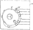
Fig. 4 has shown the part that the ratio below of the equipment shown in Fig. 2 is amplified;
Fig. 5 is the perspective view from the element top of Fig. 1 to 4, with the capping (for clarity sake having omitted stopper) of simplifying;
Fig. 6 is the top plan view of the preferred capping used together with the element with Fig. 1-4;
Fig. 7 is the perspective view of the downside of the capping shown in Fig. 6;
Fig. 8 is that wherein stopper is positioned at the ready position of top from the perspective view of the capping top of Fig. 6 and 7;
Fig. 9 is the cutaway view of the capping of Fig. 8, and wherein stopper is positioned at the ready position of top;
Figure 10 is the profile perspective of the capping of Fig. 8, and wherein stopper is positioned at the ready position of top;
Figure 11 is the cutaway view that ratio is amplified, and has shown the capping of Fig. 6-10 on the element that is positioned at Fig. 1-5, and wherein stopper is positioned in the ready position of top;
Figure 12-15th, corresponding to a series of views of Fig. 8-11, shown stopper be in below, on position that depress, state of activation;
Figure 15 A is the schematic diagram of the production stage of shown equipment;
Figure 16 A and 16B are respectively top plan view and the lower side plan view of a part of the element of Fig. 1-5, in figure, element is with the simplification capping (for clarity sake having omitted stopper) of Fig. 5, wherein capping is in the first position, top view has also shown that each several part is in element Zhong position, and underside view has also been shown the downside of capping;
Figure 17 A and 17B are the views that is similar to Figure 16 A and 16B, and wherein capping is in the second place;
Figure 18 A and 18B are the views that is similar to Figure 16 A and 16B, and wherein capping is in San position; And
Figure 19 and 20 is schematic diagrames of downside of the element of Fig. 1-5, has shown that capping is in respectively second and operation during San position.
Figure 21 is the view of downside of the control element of preferred combination of the present invention, and this control element comprises stopper, the apparatus for breaking of sealing device, destructible container, and serves as the capping of sample well.Figure 22 is the top view of same control element.
The specific embodiment
Accompanying drawing shown there is capillary channel or path, for carrying out the sample test equipment of aggegation chemical examination, for example, aggegation chemical examination is disclosed in WO2004/083859 and WO2006/046054 conventionally.
This equipment comprises two critical pieces: sampling element 10 and capping 12.Fig. 5 and 16-18 shown capping 12 ' simple version so that understand, wherein for clarity sake omitted stopper.The current preferred version of capping 12 has been shown in Fig. 6-15.Capping 12 and 12 ' is identical in function.
As Figure 1-5, element 10 comprises rectangular slab rigidity, flat, injection moulding Merlon, is of a size of 136 millimeters * 57 millimeters * 2.5 millimeters.On the upper surface 16 of element, be formed with upright collar 14, have a series of grooves on 20 below that are formed on element to form the unlimited groove 18 in top.As described below, this element is run through in a series of hole, is opened on above and below.
As best shown in Figure 3, collar 14 is positioned near the Yi Ge angle of element, and it comprises main partial circle part 24---form the part that radius is about the circle of 10 millimeters, and less important partial circle part 26---form the part that radius is about the circle of 6 millimeters.Collar 14 defines the sampled well that is roughly tubular 27 on the upper surface that is positioned at element 10.A pair of rib 28 stretches out in a part for the outer surface of part 24, and the slot-shaped openings 30 of arc runs through this element below rib.This opening is not carried out any function in the use of equipment, and its existence is the reason of producing due to molding.The upper surface that is positioned at collar of element comprises a sunk part 32 that is positioned at the similar funnel less important part 26, circular of collar, lead to the thief hole 34 that runs through element, the remainder of the upper surface that is positioned at collar of element is slightly recessed, and as downward-sloping shown in 36, Figure 11 and 15 has also shown this point.The spike-tooth 40 of four scallop structures extends upward from the recessed portion 36 of upper surface.
Groove 18 defines two capillary tracks similarly, side by side, that be arranged in mirror image, forms test tracks and controls track.Each track comprises the main line 42,42 ' that is arranged in U-shaped structure, and the major branch with approximately 100 millimeters long is dry.These grooves extend to each main line steam vent 44,44 ' through element 10 from sample inlet 34.Each track also comprise overflow groove 46,46 ', overflow groove extends to side shoot and turns to 90 ° towards sample inlet, to extend backward from relevant main line, and ends at each overflow groove steam vent 48,48 ' that runs through element 10.Overflow groove can be than tap drain groove width.Short side trench 50,50 ' extends from each main line, in the downstream slightly of the joint with overflow groove, ends at each side trench opening 52,52 ' that runs through element 10, and each side trench opening is counterbore at element upper surface.
Capping 12,12 ' comprises and is roughly columnar injection moulding acronitrile-butadiene-styrene (ABS) rigid body 60,34 millimeters of its diameters, highly approximately 10 millimeters.Main body 60 has the annular upper wall 62 with central opening 64, and the sidewall 66 with the outer surface 68 of rib reinforcement.Inner post cylindrical skirt 70 extends from the lower surface of roof 62, is positioned at its center, and around central opening 64, and its diameter is greater than the diameter of opening 64.Cannelure 72 is formed between the inner surface of sidewall 66 and the outer surface in skirt section 70.The narrow major part 74 of groove 72 has parallel sidewall, and this parallel sidewall sections is limited by the thicker section 76 of the part-circular of sidewall, and this part 74 is configured to and size is designed to be applicable to be enclosed within the major part 24 of collar of element 10.Remaining of groove 72, less important, wider part 78 parts are limited by the thinner bending section 80 of sidewall, and this part 78 is wide to being enough to be enclosed within the less important part 24 of collar of element 10.The arc length of enclosure portion 78 is longer than the arc length of collar part 26, therefore when capping 12 is positioned on element 10 and when groove 72 is positioned on collar, capping 12 can reach approximately 90 ° with respect to the conditional degree of rotation of element 10, scope of activities by the outer surface of the two ends of the inner face of thinner side wall sections 80 and less important collar part 26 in abutting connection with determining.
The roof 62 of capping 12 comprises sunk part 82, and this sunk part has the sample inlet hole 84 of running through wherein, and this sample inlet hole is arranged in the core of wider slot part 78 and is symmetrically located at wider slot part 78.Hole 84 coordinates with the sample inlet 34 on element 10, can describe this point below.
The lower surface of the thinner side wall sections 80 of capping comprises the groove 86,88 of two elongated part annular, and each groove ends at a circular recess.Shore hardness is that the cylindricality soft rubber insert 90,92,94,96 of the thermoplastic elastomer (TPE) (TPE) of 40A is mounted in each recess, each insert slightly protrude from sidewall below, form 4 with capillary groove steam vent 44,44 ', 48, the 48 ' seal coordinating, this point can be described below.
Capping 12 comprises the ABS stopper 100 of the rigidity that is roughly cylindricality, and this stopper is arranged in the central opening 64 of capping main body 60, and by series of thin, rupturable net 102 is connected in this main body.Capacity is that the fluid-filled tubular polypropylene capsule 104 of 400 microlitres is installed in stopper 100 lower end, and the size of this capsule is made into applicable being closely assemblied in skirt section 70, for sliding vertically within it.Stopper 100 and capsule 104 can the ready position above as shown in Fig. 8-11 and as shown in Figure 12-14 below active position between movable, by applying suitable downward power to stopper so that net 102 breaks, and stopper 100 and capsule 104 are moved vertically with respect to capping main body 60 and element 10, capsule 104 is stapled on spike-tooth 40, thus by the release of fluid including in the well 27 being formed in collar 14.
The compliant foil 106 (Figure 15 A) that form is polycarbonate plate 0.06 millimeters thick, limpid is secured on the lower surface 20 of element 10 by laser weld, with covering groove 42,42 ', 46,46 ' and side trench 50,50 ', and they are transformed into the capillary channel of sealing, here also referred to as capillary path.
Bicarbonate such as ABS or Merlon is hydrophobic, this means that aqueous fluids can not flow well in passage.In order to address this problem, capillary channel inner surface is processed, so that the shallow layer of one deck Tween20 surfactant (Tween is trade mark) to be provided, thereby gives capillary surface hydrophily.This is undertaken by application of vacuum: by the openend at passage, apply suction, the deionized water solution of Tween20 (by volume comprising 0.25% Tween20) was taken out to capillary channel.This is schematically illustrated in Figure 15 A.Tween20 solution applies by sample inlet hole 34, and a pair of sucker is applied on the steam vent of capillary channel end, is first applied to main channel, is then applied to overflow ducts.Vacuum applies by vacuum generator, and for Tween20 solution was inhaled to passage, as shown in the arrow in Figure 15 A.Then, element 10 is left on low temperature drying in baking oven, to evaporate the water section in solution, leaves Tween20 and be precipitated as skim on interior capillary surface, thereby make surface hydrophilic.
Quality Control Function is also fulfiled in this processing because it can show whether any capillary channel is blocked, for example due to the sealing of faulty molding, paper tinsel is bad or passage in there is fragment or foreign matter, thereby can abandon defective element in this stage.
This equipment is for example prepared to be used in, in aggegation chemical examination (disclosed in WO2004/083859 and WO2006/046054), by by side trench 50, the agglutination reagent of controlled quentity controlled variable being deposited in test tracks passage 42, by opening 52, adds reagent.The liquid that comprises reagent is supplied by opening 52, and vacuum action is on steam vent 44.To process same mode with Tween as above, this,, for liquid being inhaled to side trench 50 and test tracks passage 42 downstream part, makes reagent be deposited on capillary wall along passage 42 downstream part.Subsequently, be dried as required.Then, by cover to produce hermetic seal with paper tinsel, carry out sealed open 52,52 '.
In the situation that only need reagent in a part for passage 42 downstream part, by the correct position in test tracks passage 42 downstream, provide another side trench and opening (not shown) (with respect to side trench 50 and opening 52), can realize this point.By opening 52 supply reagent liquid, and apply vacuum at another described opening part, reagent can only be deposited in centre (intervening) section of passage 42.Can use in a similar manner in a plurality of positions auxiliary side trench and opening that reagent (identical or different) precipitation is provided repeatedly, thereby the present invention can be loaded into the reagent of selection in capillary channel.
Then capping 12 is placed on the collar 14 of sampling element 10, and as shown in Figure 16 A and 16B, stopper 100 is in ready position, and capping is in primary importance.At this primary importance place, equipment is in dormant state.The sample inlet hole 84 of capping is oriented to avoid be communicated with sampled well 27 fluids of element, and as shown in Figure 16 A and 16B, so the sample inlet hole 34 of element is blocked effectively.Neither one passage steam vent is sealed.
Equipment under this state can be wrapped up, to distribute and sell, for example, is sealed in the paper tinsel bag of air proof and steam.
When equipment need to be used, capping 12 is rotated to the second place, as shown in Figure 17 A and 17B.Gai position, the sample inlet hole 84 of capping is positioned in the top of the part 26 of sampled well 27, thereby is communicated with sample inlet hole 34 fluids of element.In addition, respectively capped insert 96,92 sealings of main line steam vent 44,44 ', the groove of overflow simultaneously steam vent 48,48 ' does not have sealed.
A certain amount of have a fluid sample to be tested (analyte that may comprise research), and for example blood sample, is added in equipment by sample inlet hole 84.The sample importantly adding is more than testing required sample, and under existing conditions, the sample of approximately 15 microlitres is suitable.Along main channel, 42,42 ' initial part flows sample fluid, then enters overflow ducts 46,46 ', as shown in figure 19.In the figure, sample represents with fill area.Sample can not be along main channel 42,42 ' flows forward, because 44,44 ' the capped sealing of main line steam vent.Like this, the sample of limited amount is present in each main channel and (is called test volume), and excessive meeting enters overflow ducts.In this embodiment, approximately 5 microlitres of the test volume in each main channel.
Then rotary closure 12 is to San position, as shown in Figure 18 A and 18B.Gai position, as primary importance place, the sample inlet hole 84 of capping is oriented to avoid be communicated with sampled well 27 fluids of element again.But overflow groove steam vent 48,48 ' is distinguished 94,90 sealings of capped insert now, and that main line steam vent 44,44 ' does not have is sealed.
Then, the fluid in capsule 104 is introduced into capillary channel.Preferably, this is after predetermined time, for example, and as shown in the timer with device-dependent.Conventionally, fluid is to catch up with (chase) buffer solution, for example, and the deionized water of the Ficoll polymer of 1% weight or distilled water solution (Ficoll is trade mark), it makes to utilize than flowing through the required few sample of amount of whole capillary system reacts, to determine test result.This realizes by operation capping stopper 100.
The stopper 100 of capping 12 is depressed, and for example, by operator's application of force, so that it is moved to active position, as shown in Figure 12 to 15, causes capsule 104 to be pierced through by spike-tooth 40, as shown in figure 15, and from capsule, discharges fluid, and flows in well 27.The capsule fluid of ,Yong cross hatched regions domain representation, for example, catch up with buffer solution as shown in figure 20, promotes sample along main channel forward.
Due to capillary flow, sample (succeeded by catching up with buffer solution) can be along main channel 42,42 ' flows.Because overflow groove steam vent 48,48 ' is now sealed, so no longer flow along overflow ducts, comprise the backflow of Bu Huixiang main channel.On the contrary, fluid fails to be convened for lack of a quorum along main channel and 42,42 ' to unencapsulated main line steam vent 44,44 ', to flow.Thereby, the sample precipitation reagent in TCH test channel of can flowing through.If the analyte of research is present in sample, will react with reagent, compare with the unreacted sample of controlling in track, can change flow behavior.
This equipment comprises near the checkout gear (not shown) being positioned at end, main channel, to detect test tracks and to control liquid in track, whether exists.Thus, can determine whether to react with agglutination reagent, and can determine the information that the analyte studied in sample exists (qualitatively or quantitative).Suitable checkout gear is not known, not within the scope of the present invention yet.
This equipment is easy to use, and relatively unskilled personnel also can use reliably, may be for patient care point.Especially, this equipment provides the sample of scheduled volume in capillary test macro for the operation by overflow ducts, and the reagent (such as catching up with buffer solution) of scheduled volume is provided from capsule.This device just is wanted very small amount of sample to be tested, for example approximately 10 to 15 microlitres.This equipment is designed to single and uses, and after being finished, is abandoned.
Figure 21 and 22 represents according to the alternate embodiment of control element of the present invention.In these embodiments, control element forms by being roughly avette element, and this avette element comprises the lower portion being positioned on control element leg, and lower portion is provided with seal member, so seal member contacts the upper surface of flat capillary path equipment.The well that is roughly tubular is formed in the upper surface of control element, and it is limited by sidewall, and has base part ,Gai hole with holes and be communicated with the sample inlet hole fluid of capillary path equipment.The pedestal of well comprises sharp cone distal protuberance.A pivoting point is provided, allows control element around this pivoting point rotation.Control element is sitting on the upper surface of flat capillary path equipment, and be positioned at primary importance place when (as shown) sample well in capillary path equipment be exposed.Sample well comprises that fluid applies region, and in use, user inserts sample well by sample.Operation control element, allows it around pivot, rotate, so that the lower portion of control element is sitting in sample well top.
Claims (21)
1. processing has a method for the parts of capillary channel, comprises allowing processing fluid by this passage, thereby leave face coat on the inner surface of passage.
2. according to the process of claim 1 wherein that face coat improves sample flowing by processed passage.
3. according to the method for claim 1, after by fluid treatment, also comprise drying steps.
4. according to the method for claim 1 or 2, wherein passage is sealed, preferably with cladding element, seals.
5. according to the method for any one in claim 1 to 4, wherein by applying vacuum in the downstream opening of passage, make to process fluid by this passage.
6. according to the method for any one in the claims, wherein processing fluid is liquid.
7. according to the method for any one in the claims, wherein the inner surface of untreated capillary channel has hydrophobicity.
8. according to the method for any one in the claims, wherein process fluid and comprise surfactant.
9. method according to Claim 8, wherein processes fluid and comprises polysorbate.
10. according to the method for claim 9, wherein process fluid and comprise polyoxyethylene sorbitan material.
11. according to the method for any one in claim 1 to 3, wherein processes fluid and comprises laboratory reagent, preferably includes agglutination reagent.
12. according to the method for any one in the claims, and wherein said parts comprise sample test equipment.
13. according to the method for any one in the claims, and wherein said parts have two or more capillary channels, and processes fluid and pass through these passages simultaneously or successively.
14. according to the method for any one in the claims, comprises that the fluid of measuring known volume is by the required time of capillary channel, and compares by untreated passage institute's time spent of same size with the fluid of same volume.
15. according to the method for any one in the claims, comprises with processing fluid and repeatedly processes capillary channel, and preferably each processing all comprises drying steps, and preferably each processing all comprises time measurement step.
16. according to the method for claim 15, wherein for each treatment step, processes fluid different.
17. according to the method for claim 16, and wherein, in single treatment, processing fluid is surfactant, and in further processing, processing fluid is reagent.
18. 1 kinds of processing have the method for the parts of capillary channel, comprising: a) allow and process fluid by this passage, to leave face coat on the inner surface of this passage; And b) allowing reagent be deposited in has in the parts of capillary channel.
19. according to the process of claim 1 wherein before this passage of sealing, by any suitable method, reagent is deposited in capillary channel.
20. 1 kinds of manufactures have the method for the parts of capillary channel, comprise: form the unlimited groove in one or more tops, with cladding element, seal these grooves to produce one or more capillary channels, then allow and process fluid by one or more passages, to leave face coat on the inner surface of one or more passages.
21. 1 kinds of parts with capillary channel, use according to the method for any one in the claims and produce.
Applications Claiming Priority (9)
| Application Number | Priority Date | Filing Date | Title |
|---|---|---|---|
| GB1104354.4 | 2011-03-15 | ||
| GBGB1104357.7A GB201104357D0 (en) | 2011-03-15 | 2011-03-15 | Dosing control device |
| GB1104357.7 | 2011-03-15 | ||
| GB1104358.5 | 2011-03-15 | ||
| GBGB1104359.3A GB201104359D0 (en) | 2011-03-15 | 2011-03-15 | Fluid flow control |
| GBGB1104354.4A GB201104354D0 (en) | 2011-03-15 | 2011-03-15 | Capillary passage components |
| GBGB1104358.5A GB201104358D0 (en) | 2011-03-15 | 2011-03-15 | Fluid dispensing device |
| GB1104359.3 | 2011-03-15 | ||
| PCT/GB2012/050572 WO2012123750A1 (en) | 2011-03-15 | 2012-03-15 | Surface preparation |
Publications (1)
| Publication Number | Publication Date |
|---|---|
| CN103517763A true CN103517763A (en) | 2014-01-15 |
Family
ID=45937435
Family Applications (3)
| Application Number | Title | Priority Date | Filing Date |
|---|---|---|---|
| CN201280023010.6A Expired - Fee Related CN103534030B (en) | 2011-03-15 | 2012-03-15 | Sample metering |
| CN201280022171.3A Pending CN103517763A (en) | 2011-03-15 | 2012-03-15 | Surface preparation |
| CN201280023020.XA Expired - Fee Related CN103517764B (en) | 2011-03-15 | 2012-03-15 | Capillary fluid flow controls |
Family Applications Before (1)
| Application Number | Title | Priority Date | Filing Date |
|---|---|---|---|
| CN201280023010.6A Expired - Fee Related CN103534030B (en) | 2011-03-15 | 2012-03-15 | Sample metering |
Family Applications After (1)
| Application Number | Title | Priority Date | Filing Date |
|---|---|---|---|
| CN201280023020.XA Expired - Fee Related CN103517764B (en) | 2011-03-15 | 2012-03-15 | Capillary fluid flow controls |
Country Status (8)
| Country | Link |
|---|---|
| US (5) | US20140037516A1 (en) |
| EP (3) | EP2686109A1 (en) |
| JP (3) | JP2014514538A (en) |
| CN (3) | CN103534030B (en) |
| AU (3) | AU2012228096B2 (en) |
| CA (3) | CA2830010A1 (en) |
| GB (3) | GB2504625A (en) |
| WO (3) | WO2012123753A1 (en) |
Families Citing this family (18)
| Publication number | Priority date | Publication date | Assignee | Title |
|---|---|---|---|---|
| US20140037516A1 (en) | 2011-03-15 | 2014-02-06 | Carclo Technical Plastics Limited | Surface preparation |
| US9409175B2 (en) * | 2012-02-28 | 2016-08-09 | Arkray, Inc. | Mixing apparatus |
| GB201216454D0 (en) * | 2012-09-14 | 2012-10-31 | Carclo Technical Plastics Ltd | Sample metering device |
| US9968930B2 (en) * | 2013-04-04 | 2018-05-15 | Surnetics, Llc | Microfluidic products with controlled fluid flow |
| JP6120440B2 (en) * | 2013-04-30 | 2017-04-26 | 国立研究開発法人産業技術総合研究所 | Microchamber and liquid mixing method |
| US9409170B2 (en) * | 2013-06-24 | 2016-08-09 | Hewlett-Packard Development Company, L.P. | Microfluidic mixing device |
| PL3074204T3 (en) * | 2013-11-27 | 2018-06-29 | F. Hoffmann-La Roche Ag | A method for laser welding a disposable test-unit |
| EP2944965A1 (en) * | 2014-05-13 | 2015-11-18 | Roche Diagnostics GmbH | Rotatable cartridge for measuring a property of a biological sample |
| US20180021773A1 (en) * | 2014-07-25 | 2018-01-25 | Loughborough University | Assay devices, methods for carrying out assays, assay kits and method for manufacturing assay devices |
| US10071373B2 (en) * | 2014-08-08 | 2018-09-11 | Ortho-Clinical Diagnostics, Inc. | Lateral-flow assay device having flow constrictions |
| TWI614498B (en) * | 2015-02-02 | 2018-02-11 | 國立清華大學 | Detection device with reagent and its manufactured therefrom |
| FR3032132A1 (en) * | 2015-02-03 | 2016-08-05 | Commissariat Energie Atomique | MICROFLUIDIC DEVICE AND METHOD FOR PRODUCING A MICROFLUIDIC DEVICE |
| WO2017056748A1 (en) * | 2015-09-28 | 2017-04-06 | パナソニックヘルスケアホールディングス株式会社 | Sensor for analyzing analyte, measurement device, and method for analyzing analyte |
| JP2017078664A (en) * | 2015-10-21 | 2017-04-27 | 東洋製罐グループホールディングス株式会社 | Immunoassay device |
| WO2018009184A1 (en) | 2016-07-06 | 2018-01-11 | Hewlett-Packard Development Company, L.P. | Microfluidic mixer |
| JP2018084511A (en) * | 2016-11-24 | 2018-05-31 | テルモ株式会社 | Body fluid measurement device set and body fluid measurement chip |
| CN107512081B (en) * | 2017-07-31 | 2019-09-10 | 北京康亿鸿科技发展有限公司 | Fluid delivery structure and fluid delivery system with the fluid delivery structure |
| NL2028817B1 (en) * | 2021-07-23 | 2023-01-30 | Micronit Holding B V | Assembly of a microfluidic device and a cap, cap, microfluidic device and method for introducing fluid into a microfluidic device |
Citations (6)
| Publication number | Priority date | Publication date | Assignee | Title |
|---|---|---|---|---|
| US20030080087A1 (en) * | 2000-03-28 | 2003-05-01 | Martin Stelzle | Process for surface modification of a micro fluid component |
| CN1454952A (en) * | 2002-05-01 | 2003-11-12 | 生命扫描有限公司 | Hydrophilic coating of medical implements |
| US20060246600A1 (en) * | 2005-04-29 | 2006-11-02 | Kimberly-Clark Worldwide, Inc. | Metering technique for lateral flow assay devices |
| CN101091115A (en) * | 2004-10-28 | 2007-12-19 | 平台诊断有限公司 | Assay system |
| US20080056947A1 (en) * | 2006-08-02 | 2008-03-06 | Michael Glauser | Microfluidic system and coating method therefor |
| CN101568829A (en) * | 2006-12-26 | 2009-10-28 | 积水化学工业株式会社 | Hemoglobin measurement method and electrophoresis apparatus |
Family Cites Families (72)
| Publication number | Priority date | Publication date | Assignee | Title |
|---|---|---|---|---|
| US3697227A (en) | 1966-05-13 | 1972-10-10 | Westinghouse Electric Corp | Chemical constituent sampler |
| US3620676A (en) * | 1969-02-20 | 1971-11-16 | Sterilizer Control Royalties A | Disposable colorimetric indicator and sampling device for liquids |
| NL179870C (en) * | 1974-08-16 | 1986-12-01 | Sarstedt Kunststoff | BARREL FOR TAKING BLOOD WITH A CAPILLARY MOUTH. |
| US3994594A (en) * | 1975-08-27 | 1976-11-30 | Technicon Instruments Corporation | Cuvette and method of use |
| SE399768B (en) * | 1975-09-29 | 1978-02-27 | Lilja Jan E | CYVETT FOR SAMPLING, MIXING OF, THE SAMPLE WITH A REAGENTS AND DIRECT PERFORMANCE OF, SPECIAL OPTICAL, ANALYSIS OF THE SAMPLE MIXED WITH THE REAGENTS |
| DK146287C (en) * | 1976-10-18 | 1984-01-30 | Radiometer As | PROCEDURE FOR DEOXYGENATION OF A BLOOD SAMPLING MATERIAL AND CAPILLAR BEARS USED BY THE PROCEDURE |
| US4233029A (en) * | 1978-10-25 | 1980-11-11 | Eastman Kodak Company | Liquid transport device and method |
| US4426451A (en) * | 1981-01-28 | 1984-01-17 | Eastman Kodak Company | Multi-zoned reaction vessel having pressure-actuatable control means between zones |
| US5144139A (en) * | 1985-08-05 | 1992-09-01 | Biotrack, Inc. | Capillary flow device |
| US4963498A (en) | 1985-08-05 | 1990-10-16 | Biotrack | Capillary flow device |
| US5164598A (en) * | 1985-08-05 | 1992-11-17 | Biotrack | Capillary flow device |
| CA1292176C (en) * | 1985-09-18 | 1991-11-19 | Joel M. Blatt | Volume metering capillary gap device for applying a liquid sample onto a reactive surface |
| US4761381A (en) * | 1985-09-18 | 1988-08-02 | Miles Inc. | Volume metering capillary gap device for applying a liquid sample onto a reactive surface |
| US5047206A (en) * | 1987-03-11 | 1991-09-10 | Wayne State University | Reagent test strip |
| US4855240A (en) * | 1987-05-13 | 1989-08-08 | Becton Dickinson And Company | Solid phase assay employing capillary flow |
| US4902629A (en) * | 1987-10-06 | 1990-02-20 | Personal Diagnostics, Inc. | Apparatus and processes for facilitating reaction between analyte and test reagent system |
| US5126247A (en) * | 1988-02-26 | 1992-06-30 | Enzymatics, Inc. | Method, system and devices for the assay and detection of biochemical molecules |
| US5200152A (en) * | 1988-03-28 | 1993-04-06 | Cytonix Corporation | Miniaturized biological assembly |
| US5065768A (en) * | 1988-09-13 | 1991-11-19 | Safe-Tec Clinical Products, Inc. | Self-sealing fluid conduit and collection device |
| US5087556A (en) * | 1989-05-17 | 1992-02-11 | Actimed Laboratories, Inc. | Method for quantitative analysis of body fluid constituents |
| AT399228B (en) | 1990-06-08 | 1995-04-25 | Avl Verbrennungskraft Messtech | METHOD FOR ANALYZING GASEOUS OR LIQUID SAMPLES AND DISPOSABLE MEASURING ELEMENT FOR EXERCISING THE METHOD |
| US5230866A (en) * | 1991-03-01 | 1993-07-27 | Biotrack, Inc. | Capillary stop-flow junction having improved stability against accidental fluid flow |
| AU1283092A (en) * | 1991-03-19 | 1992-09-24 | White Consolidated Industries, Inc. | Refrigerator system with subcooling flow control valve |
| US5607863A (en) * | 1991-05-29 | 1997-03-04 | Smithkline Diagnostics, Inc. | Barrier-controlled assay device |
| US5468648A (en) * | 1991-05-29 | 1995-11-21 | Smithkline Diagnostics, Inc. | Interrupted-flow assay device |
| US5278079A (en) | 1992-09-02 | 1994-01-11 | Enzymatics, Inc. | Sealing device and method for inhibition of flow in capillary measuring devices |
| CN1052484C (en) * | 1993-11-05 | 2000-05-17 | 道农业科学公司 | 5-Alkoxy [1,2,4] triazolo [1,5,-C] pyrimidine -2[3H]-thione compounds and their use |
| JP3237540B2 (en) | 1996-09-30 | 2001-12-10 | 富士レビオ株式会社 | Apparatus for supplying liquid to matrix and test device having the same |
| US6654625B1 (en) * | 1999-06-18 | 2003-11-25 | Therasense, Inc. | Mass transport limited in vivo analyte sensor |
| US20010003286A1 (en) | 1999-07-14 | 2001-06-14 | Jay E. Philippbar | Flood control device |
| US6616819B1 (en) * | 1999-11-04 | 2003-09-09 | Therasense, Inc. | Small volume in vitro analyte sensor and methods |
| CA2391743A1 (en) * | 1999-11-15 | 2001-05-25 | I-Stat Corporation | Apparatus and method for assaying coagulation in fluid samples |
| WO2001068238A2 (en) * | 2000-03-14 | 2001-09-20 | Micronics, Inc. | Microfluidic analysis cartridge |
| US6561208B1 (en) | 2000-04-14 | 2003-05-13 | Nanostream, Inc. | Fluidic impedances in microfluidic system |
| WO2002023163A1 (en) * | 2000-09-15 | 2002-03-21 | California Institute Of Technology | Microfabricated crossflow devices and methods |
| US6584791B2 (en) * | 2001-04-05 | 2003-07-01 | Bristol Compressors, Inc. | Pressure equalization system and method |
| GB0129816D0 (en) | 2001-12-13 | 2002-01-30 | The Technology Partnership Plc | Testing device for chemical or biochemical analysis |
| US7459127B2 (en) * | 2002-02-26 | 2008-12-02 | Siemens Healthcare Diagnostics Inc. | Method and apparatus for precise transfer and manipulation of fluids by centrifugal and/or capillary forces |
| US7419821B2 (en) | 2002-03-05 | 2008-09-02 | I-Stat Corporation | Apparatus and methods for analyte measurement and immunoassay |
| US8128889B2 (en) * | 2002-04-30 | 2012-03-06 | Arkray, Inc. | Analyzing article, analyzer and method of analyzing a sample using the analyzing article, and a method of forming an opening in the analyzing article |
| EP1419818B1 (en) * | 2002-11-14 | 2013-10-30 | Boehringer Ingelheim microParts GmbH | Device for sequential transport of liquids by capillary forces |
| GB0306098D0 (en) * | 2003-03-18 | 2003-04-23 | Platform Diagnostics Group Ltd | Sample testing device |
| JP3768486B2 (en) * | 2003-03-20 | 2006-04-19 | 株式会社エンプラス | Micro fluid handling equipment |
| JP2007504438A (en) * | 2003-09-01 | 2007-03-01 | インバーネス・メデイカル・スウイツツアーランド・ゲゼルシヤフト・ミツト・ベシユレンクテル・ハフツング | Sampling device using capillary action |
| GB2408801A (en) * | 2003-12-03 | 2005-06-08 | Boc Group Plc | Detection of seal leak using differential pressure measurement |
| US20060183216A1 (en) | 2005-01-21 | 2006-08-17 | Kalyan Handique | Containers for liquid storage and delivery with application to microfluidic devices |
| US20070014695A1 (en) | 2005-04-26 | 2007-01-18 | Applera Corporation | Systems and Methods for Multiple Analyte Detection |
| JP4630785B2 (en) * | 2005-09-30 | 2011-02-09 | 富士フイルム株式会社 | Weighing chip and inspection method using the same |
| WO2007019479A2 (en) | 2005-08-04 | 2007-02-15 | Helicos Biosciences Corporation | Multi-channel flow cells |
| EP1920246B1 (en) | 2005-08-31 | 2010-03-10 | Egomedical Technologies AG | Coagulation test system |
| US8936945B2 (en) * | 2005-11-17 | 2015-01-20 | The Regents Of The University Of Michigan | Compositions and methods for liquid metering in microchannels |
| JP2007139658A (en) * | 2005-11-21 | 2007-06-07 | Sharp Corp | Allergen detection method and allergen detection device |
| US20080006530A1 (en) * | 2006-06-19 | 2008-01-10 | Handani Winarta | Capillary Flow Control in a Flow Channel |
| EP1878498A1 (en) | 2006-07-14 | 2008-01-16 | Roche Diagnostics GmbH | Handling kit for analyzing a liquid sample by nucleic acid ampification |
| CN200965510Y (en) * | 2006-11-01 | 2007-10-24 | 中国科学院大连化学物理研究所 | A continuous flow hyperpolarization Xe gas generation and sample former position processing device |
| US20080113391A1 (en) * | 2006-11-14 | 2008-05-15 | Ian Gibbons | Detection and quantification of analytes in bodily fluids |
| JP4852399B2 (en) * | 2006-11-22 | 2012-01-11 | 富士フイルム株式会社 | Two-component merger |
| JP2008151771A (en) * | 2006-11-22 | 2008-07-03 | Fujifilm Corp | Micro fluid chip |
| WO2008078781A1 (en) * | 2006-12-26 | 2008-07-03 | Sekisui Chemical Co., Ltd. | Hemoglobin measurement method and electrophoresis apparatus |
| WO2008096492A1 (en) | 2007-02-05 | 2008-08-14 | Shimadzu Corporation | Reaction container plate and reaction processing method |
| EP1977829A1 (en) | 2007-03-29 | 2008-10-08 | Roche Diagnostics GmbH | Device for performing multiple analyses in parallel |
| JP5532218B2 (en) | 2007-09-10 | 2014-06-25 | 日本電気株式会社 | Sample filling device |
| JP4900485B2 (en) | 2007-11-15 | 2012-03-21 | 株式会社島津製作所 | Reaction vessel plate and reaction processing method |
| WO2009078107A1 (en) | 2007-12-19 | 2009-06-25 | Shimadzu Corporation | Dispensing device |
| EP2275824B1 (en) * | 2008-05-09 | 2019-01-02 | Konica Minolta Medical & Graphic, Inc. | Microchip and microchip liquid supply method |
| EP2282190B1 (en) | 2008-05-29 | 2017-07-12 | Nippon Telegraph and Telephone Corporation | Flow cell and liquid delivery method |
| US20090318303A1 (en) * | 2008-06-20 | 2009-12-24 | International Business Machines Corporation | Microfluidic selection of library elements |
| JP2010085129A (en) * | 2008-09-29 | 2010-04-15 | Fujifilm Corp | Microfluid chip |
| US8247191B2 (en) | 2008-11-13 | 2012-08-21 | Ritzen Kalle | Disposable cassette and method of use for blood analysis on blood analyzer |
| SG176172A1 (en) | 2009-05-26 | 2011-12-29 | Agency Science Tech & Res | A microfluidic device |
| EP2608828B1 (en) * | 2010-08-26 | 2016-09-14 | Spot on Sciences, Inc. | Biological fluid sampling and storage apparatus |
| US20140037516A1 (en) | 2011-03-15 | 2014-02-06 | Carclo Technical Plastics Limited | Surface preparation |
-
2012
- 2012-03-15 US US14/004,772 patent/US20140037516A1/en not_active Abandoned
- 2012-03-15 CN CN201280023010.6A patent/CN103534030B/en not_active Expired - Fee Related
- 2012-03-15 JP JP2013558510A patent/JP2014514538A/en active Pending
- 2012-03-15 US US14/004,750 patent/US9044757B2/en not_active Expired - Fee Related
- 2012-03-15 GB GB1317946.0A patent/GB2504625A/en not_active Withdrawn
- 2012-03-15 CA CA2830010A patent/CA2830010A1/en not_active Abandoned
- 2012-03-15 GB GB1317947.8A patent/GB2505785A/en not_active Withdrawn
- 2012-03-15 JP JP2013558511A patent/JP2014508306A/en active Pending
- 2012-03-15 EP EP12714829.4A patent/EP2686109A1/en not_active Withdrawn
- 2012-03-15 CA CA2830082A patent/CA2830082A1/en not_active Abandoned
- 2012-03-15 AU AU2012228096A patent/AU2012228096B2/en not_active Ceased
- 2012-03-15 AU AU2012228098A patent/AU2012228098B2/en not_active Ceased
- 2012-03-15 JP JP2013558509A patent/JP2014514141A/en active Pending
- 2012-03-15 CN CN201280022171.3A patent/CN103517763A/en active Pending
- 2012-03-15 CN CN201280023020.XA patent/CN103517764B/en not_active Expired - Fee Related
- 2012-03-15 WO PCT/GB2012/050575 patent/WO2012123753A1/en active Application Filing
- 2012-03-15 WO PCT/GB2012/050573 patent/WO2012123751A1/en active Application Filing
- 2012-03-15 AU AU2012228095A patent/AU2012228095A1/en not_active Abandoned
- 2012-03-15 EP EP12713266.0A patent/EP2686108B1/en not_active Not-in-force
- 2012-03-15 US US14/004,775 patent/US20130344617A1/en not_active Abandoned
- 2012-03-15 EP EP12713265.2A patent/EP2686107A1/en not_active Withdrawn
- 2012-03-15 WO PCT/GB2012/050572 patent/WO2012123750A1/en active Application Filing
- 2012-03-15 CA CA2830015A patent/CA2830015A1/en not_active Abandoned
- 2012-03-15 GB GB1317948.6A patent/GB2504022A/en not_active Withdrawn
-
2015
- 2015-04-28 US US14/697,721 patent/US9352316B2/en not_active Expired - Fee Related
- 2015-04-28 US US14/697,747 patent/US20150238962A1/en not_active Abandoned
Patent Citations (7)
| Publication number | Priority date | Publication date | Assignee | Title |
|---|---|---|---|---|
| US20030080087A1 (en) * | 2000-03-28 | 2003-05-01 | Martin Stelzle | Process for surface modification of a micro fluid component |
| CN1454952A (en) * | 2002-05-01 | 2003-11-12 | 生命扫描有限公司 | Hydrophilic coating of medical implements |
| CN101091115A (en) * | 2004-10-28 | 2007-12-19 | 平台诊断有限公司 | Assay system |
| US20060246600A1 (en) * | 2005-04-29 | 2006-11-02 | Kimberly-Clark Worldwide, Inc. | Metering technique for lateral flow assay devices |
| CN101166978A (en) * | 2005-04-29 | 2008-04-23 | 金伯利-克拉克环球有限公司 | Metering technique for lateral flow assay devices |
| US20080056947A1 (en) * | 2006-08-02 | 2008-03-06 | Michael Glauser | Microfluidic system and coating method therefor |
| CN101568829A (en) * | 2006-12-26 | 2009-10-28 | 积水化学工业株式会社 | Hemoglobin measurement method and electrophoresis apparatus |
Also Published As
Similar Documents
| Publication | Publication Date | Title |
|---|---|---|
| CN103517763A (en) | Surface preparation | |
| CN106489072B (en) | The rotating cylinder for being used to analyze biological sample with measuring room | |
| US11406979B2 (en) | Rotatable cartridge for processing and analyzing a biological sample and dispensing method therewith | |
| US9808801B2 (en) | Rotatable cartridge for measuring a property of a biological sample | |
| US20150290643A1 (en) | Sample Metering Device | |
| US20130186512A1 (en) | Microfluidic device with a chamber for storing a liquid |
Legal Events
| Date | Code | Title | Description |
|---|---|---|---|
| C06 | Publication | ||
| PB01 | Publication | ||
| SE01 | Entry into force of request for substantive examination | ||
| SE01 | Entry into force of request for substantive examination | ||
| C02 | Deemed withdrawal of patent application after publication (patent law 2001) | ||
| WD01 | Invention patent application deemed withdrawn after publication |
Application publication date: 20140115 |