JP7007799B2 - Blood sampling device with capillary structure - Google Patents
Blood sampling device with capillary structure Download PDFInfo
- Publication number
- JP7007799B2 JP7007799B2 JP2016245652A JP2016245652A JP7007799B2 JP 7007799 B2 JP7007799 B2 JP 7007799B2 JP 2016245652 A JP2016245652 A JP 2016245652A JP 2016245652 A JP2016245652 A JP 2016245652A JP 7007799 B2 JP7007799 B2 JP 7007799B2
- Authority
- JP
- Japan
- Prior art keywords
- cartridge
- blood
- capillary
- sample
- rotation
- Prior art date
- Legal status (The legal status is an assumption and is not a legal conclusion. Google has not performed a legal analysis and makes no representation as to the accuracy of the status listed.)
- Active
Links
Images


Classifications
-
- G—PHYSICS
- G01—MEASURING; TESTING
- G01N—INVESTIGATING OR ANALYSING MATERIALS BY DETERMINING THEIR CHEMICAL OR PHYSICAL PROPERTIES
- G01N33/00—Investigating or analysing materials by specific methods not covered by groups G01N1/00 - G01N31/00
- G01N33/48—Biological material, e.g. blood, urine; Haemocytometers
- G01N33/483—Physical analysis of biological material
- G01N33/487—Physical analysis of biological material of liquid biological material
- G01N33/49—Blood
- G01N33/491—Blood by separating the blood components
-
- G—PHYSICS
- G01—MEASURING; TESTING
- G01N—INVESTIGATING OR ANALYSING MATERIALS BY DETERMINING THEIR CHEMICAL OR PHYSICAL PROPERTIES
- G01N1/00—Sampling; Preparing specimens for investigation
- G01N1/28—Preparing specimens for investigation including physical details of (bio-)chemical methods covered elsewhere, e.g. G01N33/50, C12Q
- G01N1/40—Concentrating samples
- G01N1/4077—Concentrating samples by other techniques involving separation of suspended solids
-
- A—HUMAN NECESSITIES
- A61—MEDICAL OR VETERINARY SCIENCE; HYGIENE
- A61B—DIAGNOSIS; SURGERY; IDENTIFICATION
- A61B10/00—Other methods or instruments for diagnosis, e.g. instruments for taking a cell sample, for biopsy, for vaccination diagnosis; Sex determination; Ovulation-period determination; Throat striking implements
- A61B10/0045—Devices for taking samples of body liquids
-
- A—HUMAN NECESSITIES
- A61—MEDICAL OR VETERINARY SCIENCE; HYGIENE
- A61B—DIAGNOSIS; SURGERY; IDENTIFICATION
- A61B5/00—Measuring for diagnostic purposes; Identification of persons
- A61B5/14—Devices for taking samples of blood ; Measuring characteristics of blood in vivo, e.g. gas concentration within the blood, pH-value of blood
- A61B5/1405—Devices for taking blood samples
- A61B5/1411—Devices for taking blood samples by percutaneous method, e.g. by lancet
-
- A—HUMAN NECESSITIES
- A61—MEDICAL OR VETERINARY SCIENCE; HYGIENE
- A61B—DIAGNOSIS; SURGERY; IDENTIFICATION
- A61B5/00—Measuring for diagnostic purposes; Identification of persons
- A61B5/15—Devices for taking samples of blood
- A61B5/150007—Details
- A61B5/150015—Source of blood
- A61B5/150022—Source of blood for capillary blood or interstitial fluid
-
- A—HUMAN NECESSITIES
- A61—MEDICAL OR VETERINARY SCIENCE; HYGIENE
- A61B—DIAGNOSIS; SURGERY; IDENTIFICATION
- A61B5/00—Measuring for diagnostic purposes; Identification of persons
- A61B5/15—Devices for taking samples of blood
- A61B5/150007—Details
- A61B5/150206—Construction or design features not otherwise provided for; manufacturing or production; packages; sterilisation of piercing element, piercing device or sampling device
- A61B5/150213—Venting means
-
- A—HUMAN NECESSITIES
- A61—MEDICAL OR VETERINARY SCIENCE; HYGIENE
- A61B—DIAGNOSIS; SURGERY; IDENTIFICATION
- A61B5/00—Measuring for diagnostic purposes; Identification of persons
- A61B5/15—Devices for taking samples of blood
- A61B5/150007—Details
- A61B5/150206—Construction or design features not otherwise provided for; manufacturing or production; packages; sterilisation of piercing element, piercing device or sampling device
- A61B5/150221—Valves
-
- A—HUMAN NECESSITIES
- A61—MEDICAL OR VETERINARY SCIENCE; HYGIENE
- A61B—DIAGNOSIS; SURGERY; IDENTIFICATION
- A61B5/00—Measuring for diagnostic purposes; Identification of persons
- A61B5/15—Devices for taking samples of blood
- A61B5/150007—Details
- A61B5/150343—Collection vessels for collecting blood samples from the skin surface, e.g. test tubes, cuvettes
-
- A—HUMAN NECESSITIES
- A61—MEDICAL OR VETERINARY SCIENCE; HYGIENE
- A61B—DIAGNOSIS; SURGERY; IDENTIFICATION
- A61B5/00—Measuring for diagnostic purposes; Identification of persons
- A61B5/15—Devices for taking samples of blood
- A61B5/150007—Details
- A61B5/150358—Strips for collecting blood, e.g. absorbent
-
- A—HUMAN NECESSITIES
- A61—MEDICAL OR VETERINARY SCIENCE; HYGIENE
- A61B—DIAGNOSIS; SURGERY; IDENTIFICATION
- A61B5/00—Measuring for diagnostic purposes; Identification of persons
- A61B5/15—Devices for taking samples of blood
- A61B5/150007—Details
- A61B5/150755—Blood sample preparation for further analysis, e.g. by separating blood components or by mixing
-
- A—HUMAN NECESSITIES
- A61—MEDICAL OR VETERINARY SCIENCE; HYGIENE
- A61B—DIAGNOSIS; SURGERY; IDENTIFICATION
- A61B5/00—Measuring for diagnostic purposes; Identification of persons
- A61B5/15—Devices for taking samples of blood
- A61B5/150007—Details
- A61B5/150801—Means for facilitating use, e.g. by people with impaired vision; means for indicating when used correctly or incorrectly; means for alarming
- A61B5/150832—Means for facilitating use, e.g. by people with impaired vision; means for indicating when used correctly or incorrectly; means for alarming by topography of the surface, e.g. Braille, embossed printing
-
- A—HUMAN NECESSITIES
- A61—MEDICAL OR VETERINARY SCIENCE; HYGIENE
- A61B—DIAGNOSIS; SURGERY; IDENTIFICATION
- A61B5/00—Measuring for diagnostic purposes; Identification of persons
- A61B5/15—Devices for taking samples of blood
- A61B5/157—Devices characterised by integrated means for measuring characteristics of blood
-
- B—PERFORMING OPERATIONS; TRANSPORTING
- B01—PHYSICAL OR CHEMICAL PROCESSES OR APPARATUS IN GENERAL
- B01D—SEPARATION
- B01D17/00—Separation of liquids, not provided for elsewhere, e.g. by thermal diffusion
- B01D17/02—Separation of non-miscible liquids
- B01D17/0217—Separation of non-miscible liquids by centrifugal force
-
- B—PERFORMING OPERATIONS; TRANSPORTING
- B01—PHYSICAL OR CHEMICAL PROCESSES OR APPARATUS IN GENERAL
- B01L—CHEMICAL OR PHYSICAL LABORATORY APPARATUS FOR GENERAL USE
- B01L3/00—Containers or dishes for laboratory use, e.g. laboratory glassware; Droppers
- B01L3/50—Containers for the purpose of retaining a material to be analysed, e.g. test tubes
- B01L3/502—Containers for the purpose of retaining a material to be analysed, e.g. test tubes with fluid transport, e.g. in multi-compartment structures
- B01L3/5021—Test tubes specially adapted for centrifugation purposes
-
- B—PERFORMING OPERATIONS; TRANSPORTING
- B01—PHYSICAL OR CHEMICAL PROCESSES OR APPARATUS IN GENERAL
- B01L—CHEMICAL OR PHYSICAL LABORATORY APPARATUS FOR GENERAL USE
- B01L3/00—Containers or dishes for laboratory use, e.g. laboratory glassware; Droppers
- B01L3/50—Containers for the purpose of retaining a material to be analysed, e.g. test tubes
- B01L3/502—Containers for the purpose of retaining a material to be analysed, e.g. test tubes with fluid transport, e.g. in multi-compartment structures
- B01L3/5027—Containers for the purpose of retaining a material to be analysed, e.g. test tubes with fluid transport, e.g. in multi-compartment structures by integrated microfluidic structures, i.e. dimensions of channels and chambers are such that surface tension forces are important, e.g. lab-on-a-chip
- B01L3/502753—Containers for the purpose of retaining a material to be analysed, e.g. test tubes with fluid transport, e.g. in multi-compartment structures by integrated microfluidic structures, i.e. dimensions of channels and chambers are such that surface tension forces are important, e.g. lab-on-a-chip characterised by bulk separation arrangements on lab-on-a-chip devices, e.g. for filtration or centrifugation
-
- B—PERFORMING OPERATIONS; TRANSPORTING
- B01—PHYSICAL OR CHEMICAL PROCESSES OR APPARATUS IN GENERAL
- B01L—CHEMICAL OR PHYSICAL LABORATORY APPARATUS FOR GENERAL USE
- B01L2200/00—Solutions for specific problems relating to chemical or physical laboratory apparatus
- B01L2200/02—Adapting objects or devices to another
- B01L2200/025—Align devices or objects to ensure defined positions relative to each other
-
- B—PERFORMING OPERATIONS; TRANSPORTING
- B01—PHYSICAL OR CHEMICAL PROCESSES OR APPARATUS IN GENERAL
- B01L—CHEMICAL OR PHYSICAL LABORATORY APPARATUS FOR GENERAL USE
- B01L2200/00—Solutions for specific problems relating to chemical or physical laboratory apparatus
- B01L2200/02—Adapting objects or devices to another
- B01L2200/026—Fluid interfacing between devices or objects, e.g. connectors, inlet details
-
- B—PERFORMING OPERATIONS; TRANSPORTING
- B01—PHYSICAL OR CHEMICAL PROCESSES OR APPARATUS IN GENERAL
- B01L—CHEMICAL OR PHYSICAL LABORATORY APPARATUS FOR GENERAL USE
- B01L2200/00—Solutions for specific problems relating to chemical or physical laboratory apparatus
- B01L2200/06—Fluid handling related problems
- B01L2200/0631—Purification arrangements, e.g. solid phase extraction [SPE]
-
- B—PERFORMING OPERATIONS; TRANSPORTING
- B01—PHYSICAL OR CHEMICAL PROCESSES OR APPARATUS IN GENERAL
- B01L—CHEMICAL OR PHYSICAL LABORATORY APPARATUS FOR GENERAL USE
- B01L2200/00—Solutions for specific problems relating to chemical or physical laboratory apparatus
- B01L2200/10—Integrating sample preparation and analysis in single entity, e.g. lab-on-a-chip concept
-
- B—PERFORMING OPERATIONS; TRANSPORTING
- B01—PHYSICAL OR CHEMICAL PROCESSES OR APPARATUS IN GENERAL
- B01L—CHEMICAL OR PHYSICAL LABORATORY APPARATUS FOR GENERAL USE
- B01L2300/00—Additional constructional details
- B01L2300/04—Closures and closing means
- B01L2300/041—Connecting closures to device or container
- B01L2300/043—Hinged closures
-
- B—PERFORMING OPERATIONS; TRANSPORTING
- B01—PHYSICAL OR CHEMICAL PROCESSES OR APPARATUS IN GENERAL
- B01L—CHEMICAL OR PHYSICAL LABORATORY APPARATUS FOR GENERAL USE
- B01L2300/00—Additional constructional details
- B01L2300/08—Geometry, shape and general structure
- B01L2300/0803—Disc shape
-
- B—PERFORMING OPERATIONS; TRANSPORTING
- B01—PHYSICAL OR CHEMICAL PROCESSES OR APPARATUS IN GENERAL
- B01L—CHEMICAL OR PHYSICAL LABORATORY APPARATUS FOR GENERAL USE
- B01L2300/00—Additional constructional details
- B01L2300/12—Specific details about materials
- B01L2300/123—Flexible; Elastomeric
-
- B—PERFORMING OPERATIONS; TRANSPORTING
- B01—PHYSICAL OR CHEMICAL PROCESSES OR APPARATUS IN GENERAL
- B01L—CHEMICAL OR PHYSICAL LABORATORY APPARATUS FOR GENERAL USE
- B01L2400/00—Moving or stopping fluids
- B01L2400/04—Moving fluids with specific forces or mechanical means
- B01L2400/0403—Moving fluids with specific forces or mechanical means specific forces
- B01L2400/0406—Moving fluids with specific forces or mechanical means specific forces capillary forces
-
- B—PERFORMING OPERATIONS; TRANSPORTING
- B01—PHYSICAL OR CHEMICAL PROCESSES OR APPARATUS IN GENERAL
- B01L—CHEMICAL OR PHYSICAL LABORATORY APPARATUS FOR GENERAL USE
- B01L2400/00—Moving or stopping fluids
- B01L2400/04—Moving fluids with specific forces or mechanical means
- B01L2400/0403—Moving fluids with specific forces or mechanical means specific forces
- B01L2400/0409—Moving fluids with specific forces or mechanical means specific forces centrifugal forces
-
- G—PHYSICS
- G01—MEASURING; TESTING
- G01N—INVESTIGATING OR ANALYSING MATERIALS BY DETERMINING THEIR CHEMICAL OR PHYSICAL PROPERTIES
- G01N1/00—Sampling; Preparing specimens for investigation
- G01N1/28—Preparing specimens for investigation including physical details of (bio-)chemical methods covered elsewhere, e.g. G01N33/50, C12Q
- G01N1/40—Concentrating samples
- G01N1/4077—Concentrating samples by other techniques involving separation of suspended solids
- G01N2001/4083—Concentrating samples by other techniques involving separation of suspended solids sedimentation
-
- G—PHYSICS
- G01—MEASURING; TESTING
- G01N—INVESTIGATING OR ANALYSING MATERIALS BY DETERMINING THEIR CHEMICAL OR PHYSICAL PROPERTIES
- G01N21/00—Investigating or analysing materials by the use of optical means, i.e. using sub-millimetre waves, infrared, visible or ultraviolet light
- G01N21/01—Arrangements or apparatus for facilitating the optical investigation
- G01N21/03—Cuvette constructions
- G01N21/07—Centrifugal type cuvettes
-
- G—PHYSICS
- G01—MEASURING; TESTING
- G01N—INVESTIGATING OR ANALYSING MATERIALS BY DETERMINING THEIR CHEMICAL OR PHYSICAL PROPERTIES
- G01N21/00—Investigating or analysing materials by the use of optical means, i.e. using sub-millimetre waves, infrared, visible or ultraviolet light
- G01N21/84—Systems specially adapted for particular applications
-
- Y—GENERAL TAGGING OF NEW TECHNOLOGICAL DEVELOPMENTS; GENERAL TAGGING OF CROSS-SECTIONAL TECHNOLOGIES SPANNING OVER SEVERAL SECTIONS OF THE IPC; TECHNICAL SUBJECTS COVERED BY FORMER USPC CROSS-REFERENCE ART COLLECTIONS [XRACs] AND DIGESTS
- Y10—TECHNICAL SUBJECTS COVERED BY FORMER USPC
- Y10T—TECHNICAL SUBJECTS COVERED BY FORMER US CLASSIFICATION
- Y10T436/00—Chemistry: analytical and immunological testing
- Y10T436/25—Chemistry: analytical and immunological testing including sample preparation
- Y10T436/25375—Liberation or purification of sample or separation of material from a sample [e.g., filtering, centrifuging, etc.]
-
- Y—GENERAL TAGGING OF NEW TECHNOLOGICAL DEVELOPMENTS; GENERAL TAGGING OF CROSS-SECTIONAL TECHNOLOGIES SPANNING OVER SEVERAL SECTIONS OF THE IPC; TECHNICAL SUBJECTS COVERED BY FORMER USPC CROSS-REFERENCE ART COLLECTIONS [XRACs] AND DIGESTS
- Y10—TECHNICAL SUBJECTS COVERED BY FORMER USPC
- Y10T—TECHNICAL SUBJECTS COVERED BY FORMER US CLASSIFICATION
- Y10T436/00—Chemistry: analytical and immunological testing
- Y10T436/25—Chemistry: analytical and immunological testing including sample preparation
- Y10T436/2575—Volumetric liquid transfer
Description
本発明は、生物学的試料用の分析試験装置に関し、詳細には、血液試料の測定を実施するための回転可能なカートリッジの設計および使用に関する。 The present invention relates to analytical testing equipment for biological samples, and more particularly to the design and use of rotatable cartridges for performing measurements on blood samples.
医療分析の分野においては、2種類の分析システム、すなわち、湿式分析システムおよび乾式化学分析システムが公知である。基本的に「湿式試薬」(液体試薬)を用いて動作する湿式分析システムは、たとえば、試料および試薬を試薬容器内に提供し、試料および試薬を試薬容器において混合し、所望の分析に関する結果(分析結果)を提供するために測定変数の特性に関して混合物を測定および分析するなど、多数の要求されるステップを介して分析を実施する。このようなステップはしばしば、参加要素の様々な動作を可能にする、技術的に複雑かつ大きな、ライン操作される分析機器を用いて実施される。この種の分析システムは、典型的には大きな医療分析検査室において用いられる。 In the field of medical analysis, two types of analytical systems, namely wet analytical systems and dry chemical analytical systems, are known. A wet analysis system that operates essentially with a "wet reagent" (liquid reagent) provides, for example, a sample and reagent in a reagent container, mixes the sample and reagent in the reagent container, and results on the desired analysis ( The analysis is performed through a number of required steps, such as measuring and analyzing the mixture with respect to the properties of the measurement variables to provide the analysis results). Such steps are often performed using technically complex and large, line-operated analytical instruments that allow various movements of the participating elements. This type of analytical system is typically used in large medical analytical laboratories.
一方で、乾式化学分析システムは、典型的にはテストエレメントに一体化されて、たとえば「テストストリップ」として実施される「乾式試薬」を用いて動作する。これらの乾式化学分析システムが用いられる場合、液体試料は、テストエレメントの試薬を溶解させ、試料および溶解した試薬の反応は、測定変数に変化をもたらし、これはテストエレメント自体で測定され得る。とりわけ、光学的に分析可能な(特に、比色分析の)分析システムがこの種において典型的であり、この場合測定変数は、変色または他の光学的に測定可能な変数である。電子化学的システムもこの種において典型的であり、この場合、電気的な測定変数の特性、詳細には所定の電圧印加時の電流が、測定領域に設けられる電極を用いてテストエレメントの測定領域において測定され得る。 On the other hand, dry chemical analysis systems operate with "dry reagents" that are typically integrated into test elements and performed, for example, as "test strips". When these dry chemical analysis systems are used, the liquid sample dissolves the reagents of the test element, and the reaction of the sample and the dissolved reagents causes changes in the measurement variables, which can be measured by the test element itself. In particular, optically analyzable (especially colorimetric) analytical systems are typical of this type, in which case the measurement variable is discoloration or other optically measurable variable. Electrochemical systems are also typical of this type, in which the characteristics of the electrical measurement variables, specifically the current when a given voltage is applied, are measured in the measurement area of the test element using electrodes provided in the measurement area. Can be measured in.
乾式化学分析システムの分析機器は通常小型であり、持ち運び可能でバッテリ駆動のものもある。システムは、たとえば、研修医による病院の病室、および、患者自身による医療分析パラメータの監視(詳細には、糖尿病患者による血中グルコース分析やワルファリン服用患者による凝固状態分析)中のいわゆる「家庭での監視」において、分散型分析(ポイントオブケア検査ともいう)のために用いられる。 Analytical instruments in dry chemical analysis systems are usually small, portable and battery-powered. The system is, for example, in the so-called "home" during hospital room by trainees and monitoring of medical analysis parameters by patients themselves (specifically, blood glucose analysis by diabetic patients and coagulation status analysis by patients taking Walfarin). In "monitoring", it is used for distributed analysis (also called point of care test).
湿式分析システムにおいては、高性能の分析機器がより複雑な多段階の反応シーケンス(「試験プロトコル」)の実施を可能にする。たとえば、免疫化学分析はしばしば、多段階の反応シーケンスを要し、この場合、「結合/遊離分離」(以下、「b/f分離」)、すなわち、結合相および遊離相の分離が必要である。ある試験プロトコルによれば、たとえば、試料は最初に、分析物のために表面上に固定化される特定の結合試薬と接触させられてもよい。これはたとえば、このような固定化試薬を表面に備えるビーズと試料を混合することによって、または、固定化試薬の被膜を備える表面上を、もしくは固定化試薬の被膜を備える多孔質基材を通って試料を搬送することによって達成され得る。続いて、結合分析物をマークし、その検出を可能にするために、マーキング試薬が同様の方法でこの表面に接触させられてもよい。より正確な分析を達成するために、後続の洗浄ステップがしばしば実施され、この場合、未結合のマーキング試薬は、少なくとも部分的に取り除かれる。多数の分析物を判定するための多くの試験プロトコルが公知であり、これらは多数の方法で異なるが、複数の反応ステップを有する複雑な操作を要し、特に、場合によってはb/f分離も必要であるという特徴を共有している。 In wet analytical systems, high performance analytical instruments allow the implementation of more complex multi-step reaction sequences (“test protocols”). For example, immunochemical analysis often requires a multi-step reaction sequence, in which case "binding / free separation" (hereinafter "b / f separation"), ie, separation of the bound and free phases is required. .. According to one test protocol, for example, a sample may first be contacted with a particular binding reagent that is immobilized on the surface for the analyte. This can be done, for example, by mixing the sample with beads that have such an immobilization reagent on the surface, or on a surface that has a coating of the immobilization reagent, or through a porous substrate that has a coating of the immobilization reagent. Can be achieved by transporting the sample. Subsequently, a marking reagent may be contacted with the surface in a similar manner to mark the binding analyte and allow its detection. Subsequent washing steps are often performed to achieve more accurate analysis, in which case unbound marking reagents are at least partially removed. Many test protocols for determining large numbers of analytes are known, which differ in many ways but require complex operations with multiple reaction steps, especially b / f separation in some cases. It shares the characteristic that it is necessary.
テストストリップおよび同様の分析エレメントは、通常、制御された多段階の反応シーケンスを可能にしない。テストストリップと同様のテストエレメントが公知であり、これは乾燥形態で試薬を供給することに加えて、全血からの赤血球の分離といったさらなる機能を可能にする。しかしながら、これらは通常、個別の反応ステップの時間シーケンスの正確な制御は可能にしない。湿式化学検査室システムはこれらの能力を提供するが、大きすぎたり、費用がかかりすぎたり、多くの用途にとっては操作が複雑すぎたりする。 Test strips and similar analytical elements usually do not allow a controlled multi-step reaction sequence. Test elements similar to test strips are known, which allow additional functions such as separation of red blood cells from whole blood in addition to supplying reagents in dry form. However, these usually do not allow precise control of the time sequence of individual reaction steps. Wet chemical laboratory systems provide these capabilities, but they are too large, too expensive, and too complex to operate for many applications.
これらのギャップを埋めるために、少なくとも1つの外部から(すなわち、テストエレメントそのものの外部のエレメントを用いて)制御される液体搬送ステップが生じるように組み入れられるテストエレメント(「制御可能なテストエレメント」)を用いて動作する分析システムが提案されている。外部からの制御は、圧力差の適用(過圧または低圧)や、力の作用の変化(たとえば、テストエレメントの姿勢変更や加速力による、重力の作用方向の変更)に基づき得る。外部からの制御は、回転速度の関数として、回転するテストエレメントに作用する遠心力によって実施され得る。 A test element (“controllable test element”) incorporated to fill these gaps with at least one externally controlled liquid transfer step (ie, using an element external to the test element itself). An analysis system that operates using is proposed. External control can be based on the application of pressure differences (overpressure or low pressure) and changes in the action of forces (eg, changes in the direction of action of gravity due to changes in the attitude of the test element or acceleration). External control can be performed by centrifugal force acting on the rotating test element as a function of rotational speed.
制御可能なテストエレメントを有する分析システムは、公知であり、典型的には、寸法安定性のプラスチック材料を備えるハウジングと、ハウジングにより囲まれる試料分析チャネルとを有し、試料分析チャネルは、しばしば、一連の複数のチャネルセクションおよびチャンバを備え、チャンバは、その間にあるチャネルセクションと比較すると拡張されている。チャネルセクションおよびチャンバを有する試料分析チャネルの構造は、プラスチック部品の型取りによって定められる。この型取りは、射出成型技術またはホットスタンプにより生成され得る。しかしながら、近年では、リソグラフィ法によって生成される微細構造がより多く用いられている。 Analytical systems with controllable test elements are known and typically have a housing with a dimensionally stable plastic material and a sample analysis channel surrounded by the housing, the sample analysis channel often. It comprises a series of multiple channel sections and chambers, the chambers being expanded compared to the channel sections in between. The structure of the sample analysis channel with the channel section and chamber is determined by the molding of the plastic parts. This molding can be produced by injection molding technology or hot stamping. However, in recent years, more microstructures produced by lithographic methods have been used.
制御可能なテストエレメントを有する分析システムは、大型の検査室システムによってのみ実施できていた試験の小型化を可能にする。また、これらは、1つの試料からの同様の分析および/または異なる試料からの同一の分析の並行した処理のために、同一の構造を繰り返し適用することによって処理の並列化を可能にする。テストエレメントは、典型的には確立された製造方法を用いて製造でき、公知の分析方法を用いて測定および分析できるということもさらなる利点である。公知の方法および製品が、このようなテストエレメントの化学的および生化学的な構成要素に用いられ得る。 Analytical systems with controllable test elements allow for miniaturization of tests that could only be performed by large laboratory systems. They also allow parallelization of the process by repeatedly applying the same structure for the parallel process of similar analysis from one sample and / or the same analysis from different samples. It is also an additional advantage that the test element can typically be manufactured using established manufacturing methods and can be measured and analyzed using known analytical methods. Known methods and products can be used for the chemical and biochemical components of such test elements.
これらの利点にもかかわらず、改良に対してはさらなる需要がある。具体的には、制御可能なテストエレメントを用いて動作する分析システムは依然として大きすぎる。可能な限り最も小型の寸法は、意図される多くの用途にとって大きな実用的意義がある。 Despite these advantages, there is further demand for improvements. Specifically, analytical systems that operate with controllable test elements are still too large. The smallest possible dimensions have great practical significance for many intended applications.
特許文献1には、分析物を検出するためのテストエレメント、およびテストエレメントを利用して分析物を検出するための方法が提供されることが記載されている。テストエレメントは、基本的に平らな円盤状であり、好ましくは、円盤状のテストエレメントの面に対して垂直な中心軸周りで回転され得る。テストエレメントは、液体試料を塗布するための試料塗布開口と、軸から離れた第1端部および軸に近い第2端部を有する、とりわけ多孔性の吸収性基材である毛管活性領域と、軸に近い領域から、軸から離れた毛管活性領域の第1端部まで延在する試料チャネルとを有する。 Patent Document 1 describes that a test element for detecting an analytical object and a method for detecting an analytical object using the test element are provided. The test element is essentially flat disc-shaped and can preferably be rotated about a central axis perpendicular to the plane of the disc-shaped test element. The test element includes a sample application opening for application of a liquid sample, a capillary active region, which is a particularly porous absorbent substrate, having a first end off the axis and a second end close to the axis. It has a sample channel extending from a region near the axis to the first end of the capillary active region away from the axis.
本発明は、独立請求項において方法および医療システムを提供する。実施形態は従属請求項においてもたらされる。 The present invention provides a method and a medical system in an independent claim. The embodiments are provided in the dependent claims.
本明細書で用いられるカートリッジは、生物学的試料を処理済の生物学的試料へと処理するための任意のテストエレメントも包含する。カートリッジは、生物学的試料について測定を実施可能にする構造または構成要素を含んでもよい。典型的なカートリッジは、米国特許第8,114,351号明細書および特許文献1に規定および説明されるようなテストエレメントである。本明細書で用いられるカートリッジは、遠心マイクロ流体ディスクともいわれ、これは「ラボオンディスク」、ラボディスクまたはマイクロ流体CDとしても公知である。 The cartridges used herein also include any test element for processing a biological sample into a processed biological sample. The cartridge may include structures or components that make measurements possible on the biological sample. A typical cartridge is a test element as defined and described in US Pat. No. 8,114,351 and Patent Document 1. The cartridges used herein are also referred to as centrifugal microfluidic discs, which are also known as "labon discs", lab discs or microfluidic CDs.
本明細書で用いられる生物学的試料は、有機体から取得された試料から抽出、複製、再現または再生された化学製品を包含する。血液試料は生物学的試料の一例であり、全血または血液製剤のいずれかである。血漿は、処理済の生物学的試料と考えられ得る。 Biological samples as used herein include chemical products extracted, replicated, reproduced or regenerated from samples obtained from organisms. A blood sample is an example of a biological sample, either whole blood or a blood product. Plasma can be considered a treated biological sample.
以下および請求項における血液試料および製品への言及は、生物学的試料を言及するように変更されてもよいことが理解される。 It is understood that references to blood samples and products in the following and in the claims may be modified to refer to biological samples.
一態様において、本発明は、カートリッジおよび血液採取装置を用いて血液試料中の分析物の量を決定する方法を提供する。カートリッジは、回転軸周りで回転されるように動作可能である。 In one aspect, the invention provides a method of determining the amount of analyte in a blood sample using a cartridge and a blood sampling device. The cartridge can operate to rotate about its axis of rotation.
血液採取装置は取り付け面を備える。血液採取装置はさらに、血液試料を保持するための毛管構造を備える。毛管構造は湾曲部を備える。毛管構造の部分は直線であってもよいが、毛管構造の少なくとも一部は湾曲している。血液採取装置はさらに、血液試料を受け取るための毛管入口を備える。血液採取装置は、異なる試料源(たとえば、静脈または毛細血管)から試料を受け取るために、2つ以上の入口を含んでもよい。たとえば、毛管入口は、血液試料に接触させられるか血液試料に隣接して配置されてもよく、その後、毛管力が毛管入口を通して毛管構造内に血液試料を引き込んでもよい。 The blood collection device has a mounting surface. The blood sampling device further comprises a capillary structure for holding a blood sample. The capillary structure comprises a bend. The portion of the capillary structure may be straight, but at least a portion of the capillary structure is curved. The blood sampling device is further equipped with a capillary inlet for receiving a blood sample. The blood collection device may include two or more inlets to receive samples from different sample sources (eg, veins or capillaries). For example, the capillary inlet may be brought into contact with the blood sample or placed adjacent to the blood sample, after which the capillary force may draw the blood sample into the capillary structure through the capillary inlet.
カートリッジは、取り付け面に取り付けられるための受け取り面を備える。カートリッジはさらに、血液採取装置から血液試料を受け取るためのカートリッジ注入口を備える。血液採取装置は、取り付け面が受け取り面に取り付けられると毛管入口がカートリッジ注入口と流体接続されるように構成される。たとえば、毛管入口は、カートリッジ注入口に、またはカートリッジ注入口内に配置され得る。別の例において、毛管入口は、カートリッジが回転されると血液試料がカートリッジ注入口に入るように配置されてもよい。たとえば、代替的には、血液採取装置は、取り付け面が受け取り面に取り付けられると毛管入口がカートリッジ注入口に、またはカートリッジ注入口の近くに配置されるように構成されるということもできる。 The cartridge has a receiving surface for mounting on the mounting surface. The cartridge also comprises a cartridge inlet for receiving a blood sample from the blood sampling device. The blood collection device is configured such that the capillary inlet is fluid-connected to the cartridge inlet when the mounting surface is attached to the receiving surface. For example, the capillary inlet may be located at the cartridge inlet or within the cartridge inlet. In another example, the capillary inlet may be arranged such that the blood sample enters the cartridge inlet as the cartridge is rotated. For example, as an alternative, the blood collection device may be configured such that the capillary inlet is located at or near the cartridge inlet when the mounting surface is attached to the receiving surface.
カートリッジはさらに、血液試料を処理済の試料へと処理するためのマイクロ流体構造を備える。マイクロ流体構造は、注入口に流体接続される。カートリッジはさらに、血液試料中の分析物の量を決定するために、処理済の試料の測定を可能にするための測定構造を備える。 The cartridge further comprises a microfluidic structure for processing a blood sample into a processed sample. The microfluidic structure is fluid connected to the inlet. The cartridge further comprises a measurement structure to allow measurement of the processed sample to determine the amount of analyte in the blood sample.
方法は、血液試料を毛管入口内に配置することを含む。これは、血液試料を毛管入口に接触させて配置するものと解釈されてもよい。毛管力はその後、毛管入口を通して毛管構造内に血液試料を引き込んでもよい。方法はさらに、取り付け面を受け取り面に取り付けることを含む。方法はさらに、毛管構造からカートリッジ注入口まで血液試料を搬送するために、カートリッジを回転軸周りで回転させることを含む。たとえば、カートリッジおよび血液採取装置を回転軸の周りで回転させることにより生じる遠心力は、血液試料を毛管構造の外に出し、カートリッジ注入口内へと入れてもよい。方法はさらに、カートリッジ注入口からマイクロ流体構造内へ血液試料を搬送するために、カートリッジを回転軸周りで回転させることを含む。方法はさらに、マイクロ流体構造を用いて血液試料を処理済の試料へと処理するために、カートリッジの回転軸周りでの回転を制御することを含む。方法はさらに、処理済の試料を測定構造へと移送するために、カートリッジの回転を制御することを含む。方法はさらに、測定構造および測定システムを用いて分析物の量を測定することを含む。 The method comprises placing a blood sample within the capillary inlet. This may be interpreted as placing the blood sample in contact with the capillary inlet. Capillary force may then draw a blood sample into the capillary structure through the capillary inlet. The method further comprises attaching the mounting surface to the receiving surface. The method further comprises rotating the cartridge about a axis of rotation in order to transport the blood sample from the capillary structure to the cartridge inlet. For example, the centrifugal force generated by rotating the cartridge and blood collection device around a axis of rotation may cause the blood sample to move out of the capillary structure and into the cartridge inlet. The method further comprises rotating the cartridge about a axis of rotation in order to transport the blood sample from the cartridge inlet into the microfluidic structure. The method further comprises controlling the rotation of the cartridge around the axis of rotation in order to process the blood sample into a treated sample using a microfluidic structure. The method further comprises controlling the rotation of the cartridge in order to transfer the treated sample to the measurement structure. The method further comprises measuring the quantity of the analyte using a measuring structure and measuring system.
測定構造は、異なる例においては異なる形態をとってもよい。たとえば、一例において測定構造は、処理済の試料のマーカーに付着する抗体を備えるクロマトグラフィーメンブレンであってもよい。分析物の量の測定を実施するためには、それゆえ蛍光マーカーが用いられてもよい。他の例において、処理済の試料は、光学的に透明な容器または領域に搬送されて、その後分光学的測定を受けてもよい。 The measurement structure may take different forms in different examples. For example, in one example, the measurement structure may be a chromatographic membrane comprising an antibody that adheres to a marker on the treated sample. Fluorescent markers may therefore be used to carry out measurements of the amount of analyte. In another example, the treated sample may be transported to an optically transparent container or region and then subjected to spectroscopic measurements.
この実施形態は、分析物の量の測定を実施するために、血液試料をカートリッジへ提供する効率的な手段を提供できることから有益である。 This embodiment is useful because it can provide an efficient means of delivering a blood sample to a cartridge for performing a measurement of the amount of analyte.
別の実施形態において、湾曲部は毛管または毛管チューブである。 In another embodiment, the bend is a capillary or capillary tube.
別の実施形態において、湾曲部は毛管停止部である。 In another embodiment, the curved portion is a capillary stop.
別の実施形態において、血液試料は全血である。 In another embodiment, the blood sample is whole blood.
別の実施形態において、血液試料は血清である。 In another embodiment, the blood sample is serum.
別の実施形態において、血液試料は血漿である。 In another embodiment, the blood sample is plasma.
別の実施形態において、試料は尿である。 In another embodiment, the sample is urine.
別の実施形態において、マイクロ流体構造は、血液試料から血漿または血清を分離させるための血液分離チャンバを備える。特許文献1は、全血試料の血液細胞分画(主に赤血球)から血清または血漿を分離することができる回転ディスクのマイクロ流体構造を示す。 In another embodiment, the microfluidic structure comprises a blood separation chamber for separating plasma or serum from a blood sample. Patent Document 1 shows a microfluidic structure of a rotating disk capable of separating serum or plasma from a blood cell fraction (mainly red blood cells) of a whole blood sample.
血液分離チャンバは、注入口に流体接続される。方法はさらに、カートリッジ注入口から血液分離チャンバ内へ血液試料を搬送するために、カートリッジを回転軸周りで回転させることを含む。方法はさらに、遠心分離によって血液試料から血漿を分離するために、カートリッジの回転軸周りでの回転を制御することを含む。マイクロ流体構造を用いて血液試料を処理済の試料へと処理するために、カートリッジの回転軸周りでの回転を制御するステップは、血漿が処理済の試料へと処理されるように実施される。 The blood separation chamber is fluid connected to the inlet. The method further comprises rotating the cartridge about a axis of rotation in order to transport the blood sample from the cartridge inlet into the blood separation chamber. The method further comprises controlling the rotation of the cartridge around the axis of rotation in order to separate the plasma from the blood sample by centrifugation. In order to process the blood sample into the treated sample using the microfluidic structure, the step of controlling the rotation of the cartridge around the axis of rotation is performed so that the plasma is processed into the treated sample. ..
別の実施形態において、カートリッジは外面を備える。取り付け面の受け取り面への取り付けは、カートリッジ注入口を外面にシールする。たとえば、血液採取装置は、そのときに外面に配置されるか、外面にスナップされるキャップまたは他の物の形態であってもよい。血液が跳ねたりこぼれたりする可能性を減らすために、外面をシールすることが有益であり得る。 In another embodiment, the cartridge comprises an outer surface. Mounting the mounting surface on the receiving surface seals the cartridge inlet on the outer surface. For example, the blood collection device may then be in the form of a cap or other object that is placed on the outer surface or snapped to the outer surface. It may be beneficial to seal the outer surface to reduce the possibility of blood splashing or spilling.
別の実施形態において、血液採取装置は第1のスナップエレメントを備える。カートリッジは、取り付け面を受け取り面にロックするために、第1のスナップエレメントと係合するように構成される第2のスナップエレメントを備える。これは、血液採取装置が一度カートリッジに取り付けられるとそこで固定されるので有益であり得る。これは、血液採取装置がでたらめに配置されたり、血液試料の一部がこぼれたりする可能性を減らし得る。付加的には、血液採取装置およびカートリッジは、同時に廃棄できる一体の構成要素を形成する。これはカートリッジのユーザが、両方の試料を同時に廃棄することをより単純にできる。スナップの使用も、カートリッジが二回使用されることを防ぐことができる。これはたとえば、分析物の量の測定結果を紛らわしくするおそれのある、血液試料のカートリッジへの二回の追加を防ぐことができる。 In another embodiment, the blood collection device comprises a first snap element. The cartridge comprises a second snap element configured to engage the first snap element in order to lock the mounting surface to the receiving surface. This can be beneficial as the blood collection device is attached to the cartridge and then secured there. This can reduce the possibility that the blood sampling device will be randomly placed or that part of the blood sample will be spilled. Additionally, the blood collection device and cartridge form an integral component that can be disposed of at the same time. This allows the user of the cartridge to more simply discard both samples at the same time. The use of snaps can also prevent the cartridge from being used twice. This can prevent, for example, the double addition of the blood sample to the cartridge, which can confuse the measurement result of the amount of the analyte.
別の実施形態において、血液採取装置は、取り付け面を受け取り面に案内するように構成される可撓性エレメントを介してカートリッジに取り付けられる。たとえば、血液採取装置は、キャップ形状であってもよい。可撓性エレメントの使用は、血液採取装置の紛失や誤配置の可能性を減らすことを助けることができるので有益であり得る。 In another embodiment, the blood collection device is attached to the cartridge via a flexible element configured to guide the attachment surface to the receiving surface. For example, the blood sampling device may be in the shape of a cap. The use of flexible elements can be beneficial as it can help reduce the possibility of loss or misplacement of the blood collection device.
別の態様において、本発明は、血液採取装置を備える医療システムを提供する。血液採取装置は、カートリッジの受け取り面に取り付けられるための取り付け面を備える。血液採取装置は、血液試料を保持するための毛管構造をさらに備える。毛管構造は湾曲部を有する。血液採取装置は、血液試料を毛管構造内に受け取るための毛管入口をさらに備える。この実施形態は、カートリッジに取り付けることができ、コンパクトに血液をカートリッジに運ぶことができるユニットを提供するので有益であり得る。 In another aspect, the invention provides a medical system with a blood sampling device. The blood collection device includes a mounting surface for mounting on the receiving surface of the cartridge. The blood sampling device further comprises a capillary structure for holding a blood sample. The capillary structure has a curved portion. The blood sampling device further comprises a capillary inlet for receiving a blood sample within the capillary structure. This embodiment may be beneficial as it provides a unit that can be attached to the cartridge and can compactly carry blood to the cartridge.
別の実施形態において、毛管構造は、毛管構造が血液試料で充填されたときにそのことを示す視覚インジケータの少なくとも一部を形成する。視覚インジケータを毛管構造内に組み込むことは、測定が実施されるときに血液試料が充分な体積を有していることを確実にするのに役立ち得るので有用である場合がある。いくつかの例では、毛管構造自体が透明または開放していてもよく、これはオペレータまたはユーザが、血液試料の体積が、分析が実施されるのに充分な量であるかどうかを確認することを可能にする視覚検査の手段を提供できる。 In another embodiment, the capillary structure forms at least a portion of a visual indicator that indicates when the capillary structure is filled with a blood sample. Incorporating a visual indicator into the capillary structure may be useful as it can help ensure that the blood sample has sufficient volume when the measurement is performed. In some examples, the capillary structure itself may be transparent or open, which allows the operator or user to confirm that the volume of the blood sample is sufficient for the analysis to be performed. Can provide a means of visual inspection that enables.
別の実施形態において、血液採取装置は、回転軸周りで回転されると遠心力によって毛管を空にすることを可能にする流体配置を有する。 In another embodiment, the blood collection device has a fluid arrangement that allows the capillaries to be emptied by centrifugal force when rotated about an axis of rotation.
別の実施形態において、血液採取装置は、毛管構造に通気するためのベントを備える。たとえば、毛管構造は毛管入口を有し、対向するもしくは反対側の端部で、または他の部分で、毛管構造はベントを有してもよい。これは、遠心力が毛管構造から血液を流出させることを可能にし得る。 In another embodiment, the blood collection device comprises a vent to ventilate the capillary structure. For example, the capillary structure may have a capillary inlet and at opposite or contralateral ends, or at other portions, the capillary structure may have a vent. This may allow centrifugal force to drain blood from the capillary structure.
別の態様において、本発明は、カートリッジをさらに備える医療システムを提供する。カートリッジは、回転軸の周りで回転されるように動作可能である。カートリッジは受け取り面を備える。カートリッジは、血液採取装置から血液試料を受け取るためのカートリッジ注入口をさらに備える。血液採取装置は、取り付け面が受け取り面に取り付けられると、毛管入口がカートリッジ注入口に配置されるように構成される。カートリッジは、血液試料を処理済の試料へと処理するために、マイクロ流体構造をさらに備える。マイクロ流体構造は、注入口に流体接続される。カートリッジは、血液試料中の分析物の量を決定するために、処理済の試料の測定を可能にする測定構造をさらに備える。この実施形態は、カートリッジおよび血液採取装置が測定のために適切な量または投与量の血液を投与する手段を提供することから有益であり得る。 In another aspect, the invention provides a medical system further comprising a cartridge. The cartridge can operate to rotate around a axis of rotation. The cartridge has a receiving surface. The cartridge further comprises a cartridge inlet for receiving a blood sample from the blood sampling device. The blood collection device is configured such that when the mounting surface is attached to the receiving surface, the capillary inlet is located at the cartridge inlet. The cartridge further comprises a microfluidic structure for processing the blood sample into the processed sample. The microfluidic structure is fluid connected to the inlet. The cartridge further comprises a measurement structure that allows measurement of the processed sample to determine the amount of analyte in the blood sample. This embodiment may be beneficial as the cartridge and blood collection device provide a means of administering an appropriate amount or dose of blood for measurement.
別の実施形態において、カートリッジは外面を備える。取り付け面の受け取り面への取り付けは、たとえば、カートリッジ注入口を外面にシールし得る。 In another embodiment, the cartridge comprises an outer surface. Mounting the mounting surface on the receiving surface may, for example, seal the cartridge inlet to the outer surface.
別の実施形態において、マイクロ流体構造は、血液試料から血漿を分離させるための血液分離チャンバを備える。血液分離チャンバは、注入口に流体接続される。この実施形態は、全血試料から血漿を取り出す手段を提供できるので有益であり得る。 In another embodiment, the microfluidic structure comprises a blood separation chamber for separating plasma from a blood sample. The blood separation chamber is fluid connected to the inlet. This embodiment can be beneficial as it can provide a means of removing plasma from a whole blood sample.
別の実施形態において、血液採取装置は第1のスナップエレメントを備える。 In another embodiment, the blood collection device comprises a first snap element.
別の実施形態において、カートリッジは、取り付け面を受け取り面にロックするために、第1のスナップエレメントと係合するように構成される第2のスナップエレメントを備える。 In another embodiment, the cartridge comprises a second snap element configured to engage the first snap element in order to lock the mounting surface to the receiving surface.
別の実施形態において、毛管構造は硬質プラスチックから形成される。毛管入口は、毛管構造に垂直である。毛管入口は、取り付け面を越えて延在する。血液採取装置は、指把持部を備える。この実施形態は、毛管構造をカートリッジ内に挿入する効率的な手段を提供できるので有益であり得る。 In another embodiment, the capillary structure is made of hard plastic. The capillary inlet is perpendicular to the capillary structure. The capillary inlet extends beyond the mounting surface. The blood sampling device includes a finger grip. This embodiment may be beneficial as it can provide an efficient means of inserting the capillary structure into the cartridge.
別の実施形態において、第1のスナップエレメントは取り付け面を越えて延びる。 In another embodiment, the first snap element extends beyond the mounting surface.
別の実施形態において、血液採取装置は、回転中にカートリッジの均衡が保たれるように、カートリッジの中心領域にスナップする。これは、カートリッジが回転軸の周りでより速い回転速度で回転される場合に有益であり得る。 In another embodiment, the blood collection device snaps to the central region of the cartridge so that the cartridge is balanced during rotation. This can be useful if the cartridge is rotated at a higher rotational speed around the axis of rotation.
別の実施形態において、毛管入口は、血液採取装置が中心領域にスナップされているときには回転軸から外れている。これは、毛管構造の外に血液を遠心分離することを容易にできる。 In another embodiment, the capillary inlet is off the axis of rotation when the blood collection device is snapped to the central region. This makes it easy to centrifuge the blood out of the capillary structure.
別の実施形態において、血液採取装置は、取り付け面を受け取り面に案内するように構成される可撓性エレメントを介してカートリッジに取り付けられる。これは、取り付け面が受け取り面と適切に嵌合するように血液採取装置を位置合わせするのに有益であり得る。 In another embodiment, the blood collection device is attached to the cartridge via a flexible element configured to guide the attachment surface to the receiving surface. This can be useful for aligning the blood collection device so that the mounting surface fits properly with the receiving surface.
別の実施形態において、血液採取装置は露出面を備える。毛管構造は、開放チャネルとして露出面に形成される。毛管入口は、開放チャネルが露出面に合流する(meet)場所に形成される。 In another embodiment, the blood collection device comprises an exposed surface. Capillary structures are formed on exposed surfaces as open channels. Capillary inlets are formed where open channels meet the exposed surface.
開放チャネルは、接続された外側チャネルを備える。チャネルは中心領域をさらに備える。チャネルは、スポークチャネルをさらに備える。スポークチャネルは、接続された外側チャネルに中心領域を接続する。接続された外側チャネルは、スポークチャネル用の毛管停止部を形成する。この実施形態は、小型で容易に視覚的に検査される血液採取装置を提供できるので有益であり得る。 The open channel comprises a connected outer channel. The channel further comprises a central region. The channel further comprises a spoke channel. The spoke channels connect the central region to the connected outer channels. The connected outer channels form a capillary stop for the spoke channels. This embodiment may be beneficial as it can provide a small, easily visually inspected blood sampling device.
いくつかの実施形態において、接続された外側チャネルは円形である。接続された外側チャネルは一部であってもよい。毛管停止部は、それゆえ毛管構造の一部を形成してもよい。 In some embodiments, the connected outer channel is circular. The connected outer channel may be partial. The capillary stop may therefore form part of the capillary structure.
別の実施形態において、接続された外側チャネルとスポークチャネルとの間の境界は、鋭利な縁部を形成する。これは毛管停止部を形成するのに有益であり得る。 In another embodiment, the boundary between the connected outer channel and the spoke channel forms a sharp edge. This can be beneficial in forming capillary stops.
別の実施形態において、中心領域とスポークチャネルとの間の境界は丸みを帯びるか滑らかである。これは、中心領域からスポークチャネルへの血液の流れを補助し得る。 In another embodiment, the boundary between the central region and the spoke channels is rounded or smooth. This may aid the flow of blood from the central region to the spoke channels.
別の実施形態において、血液採取装置は、フォイル部を備える。血液採取装置は、成形部をさらに備える。成形部はプラスチックである。毛管構造および毛管入口は、成形部に形成される。湾曲部は平面に対して平行である。フォイル部は平面に対して平行である。フォイル部は毛管構造の壁を形成する。 In another embodiment, the blood collection device comprises a foil section. The blood sampling device further includes a molding unit. The molded part is plastic. The capillary structure and capillary inlet are formed in the molded portion. The bend is parallel to the plane. The foil portion is parallel to the plane. The foil portion forms the wall of the capillary structure.
熱成形されるという語は、たとえば、ブロー成形、深絞りまたはエンボス加工されることをいってもよい。 The term thermoformed may refer to, for example, blow molding, deep drawing or embossing.
別の実施形態において、血液採取装置は、隆起した指把持部をさらに備える。隆起した指把持部は、熱成形部から形成される。毛管構造は、フォイル部から第1の距離まで延びる。隆起した指把持部は、フォイル部から第2の距離まで延びる。第2の距離は第1の距離よりも大きい。これは、血液採取装置の容易な把持を可能にし得る。 In another embodiment, the blood collection device further comprises a raised finger grip. The raised finger grip is formed from a thermoformed portion. The capillary structure extends from the foil to a first distance. The raised finger grip extends from the foil to a second distance. The second distance is greater than the first distance. This may allow easy gripping of the blood collection device.
別の実施形態において、湾曲部は、隆起した指把持部を少なくとも部分的に取り囲む。これは、血液採取装置をより小型に作製するのに有用であり得る。 In another embodiment, the bend surrounds the raised finger grip at least partially. This can be useful for making blood sampling devices smaller.
別の実施形態において、隆起した指把持部は、血液採取装置をカートリッジで位置合わせするために用いることができる。たとえば、カートリッジには、指把持部を受け取る凹部があってもよい。これに関して、これは、血液試料の採取中に血液採取装置を保持するため、および血液採取装置をカートリッジ内に配置またはロックするための両方に指把持部が有用であり得るために、有益であり得る。 In another embodiment, the raised finger grip can be used to align the blood collection device with the cartridge. For example, the cartridge may have a recess that receives the finger grip. In this regard, this is beneficial because the finger grip can be useful both for holding the blood collection device during blood sampling and for placing or locking the blood collection device within the cartridge. obtain.
別の実施形態において、取り付け面は平面に平行である。 In another embodiment, the mounting surface is parallel to the plane.
別の実施形態において、毛管構造は平面に平行である。 In another embodiment, the capillary structure is parallel to the plane.
別の実施形態において、医療システムは、カートリッジの回転軸周りでの回転を制御するためのカートリッジスピナをさらに備える。これは、回転が自動化されて実施され得るようにカートリッジを回転軸の周りで回転させるときに有益であり得る。 In another embodiment, the medical system further comprises a cartridge spinner for controlling the rotation of the cartridge about its axis of rotation. This can be beneficial when rotating the cartridge around a axis of rotation so that rotation can be automated and performed.
別の実施形態において、医療システムは、医療システムを制御するための機械が実行可能な命令をプロセッサに記憶するメモリを備える。機械が実行可能な命令の実行は、カートリッジスピナを制御することによって毛管構造の血液試料をカートリッジ注入口まで搬送するために、プロセッサに、カートリッジを回転軸周りで回転させる。機械が実行可能な命令の実行はさらに、カートリッジスピナを制御することによってカートリッジ注入口からマイクロ流体構造へ血液試料を搬送するために、プロセッサに、カートリッジを回転軸周りで回転させる。機械が実行可能な命令の実行はさらに、カートリッジスピナを制御することによってマイクロ流体構造を用いて血液試料を処理済の試料へと処理するために、プロセッサに、カートリッジの回転軸周りでの回転を制御させる。機械が実行可能な命令の実行はさらに、カートリッジスピナを制御することによって処理済の試料を測定構造へ移送するために、プロセッサに、カートリッジの回転を制御させる。機械が実行可能な命令の実行はさらに、プロセッサに、測定構造および測定システムを用いて分析物の量を測定させる。 In another embodiment, the medical system comprises a memory in which a processor stores instructions that can be executed by a machine to control the medical system. Execution of machine-executable instructions causes the processor to rotate the cartridge around a axis of rotation in order to deliver a blood sample of capillary structure to the cartridge inlet by controlling the cartridge spinner. Execution of machine-executable instructions also causes the processor to rotate the cartridge around a axis of rotation in order to transport the blood sample from the cartridge inlet to the microfluidic structure by controlling the cartridge spinner. Execution of machine-executable instructions also causes the processor to rotate the cartridge around the axis of rotation in order to process the blood sample into a processed sample using a microfluidic structure by controlling the cartridge spinner. Let it be controlled. Execution of machine-executable instructions also causes the processor to control the rotation of the cartridge in order to transfer the processed sample to the measurement structure by controlling the cartridge spinner. Execution of machine-executable instructions also causes the processor to measure the quantity of the analyte using a measuring structure and measuring system.
別の実施形態において、機械が実行可能な命令の実行はさらに、カートリッジスピナを制御することによってカートリッジ注入口から血液分離チャンバ内へ血液試料を移送するために、プロセッサに、カートリッジを回転軸周りで回転させる。機械が実行可能な命令の実行はさらに、カートリッジスピナを制御することによって遠心分離により血液試料から血漿を分離させるために、プロセッサに、カートリッジの回転軸周りでの回転を制御させる。機械が実行可能な命令の実行はさらに、カートリッジスピナを制御することによってマイクロ流体構造を用いて血漿を処理済の試料へと処理するために、プロセッサに、カートリッジの回転軸周りでの回転を制御させる。 In another embodiment, the execution of machine-executable instructions further transfers the cartridge from the cartridge inlet to the blood separation chamber into the processor by controlling the cartridge spinner, around the axis of rotation of the cartridge. Rotate. Execution of machine-executable instructions also causes the processor to control the rotation of the cartridge around the axis of rotation in order to separate the plasma from the blood sample by centrifugation by controlling the cartridge spinner. Execution of machine-executable instructions also controls the processor to rotate the cartridge around the axis of rotation in order to process the plasma into a treated sample using a microfluidic structure by controlling the cartridge spinner. Let me.
以下において、本発明の実施形態は、例示のみを目的として図面を参照することによってより詳細に説明される。 Hereinafter, embodiments of the present invention will be described in more detail by reference to the drawings for purposes of illustration only.
これらの図面において同様の番号を付された要素は、同一の要素であるか、同一の機能を実施する。すでに記載した要素は、機能が同一である場合には、後の図面においては必ずしも説明されない。 Elements similarly numbered in these drawings are the same elements or perform the same function. The elements already described are not necessarily described in later drawings if they have the same function.
カートリッジは、たとえば、カバーが取り付けられて、プラスチックから作製または形成されてもよい。マイクロ流体構造は、いくつかの例においては、成形されたプラスチック片およびカバーによって形成されてもよい。 The cartridge may be made or formed from plastic, for example, with a cover attached. The microfluidic structure may be formed by molded plastic pieces and covers in some examples.
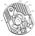
図1は、外側のカバー面のないカートリッジ100の一部を示す。図1は、正面図であり、図2は後面または背面図である。カートリッジの受け取り面自体は図1および図2には示されていない。図1は、マイクロ流体構造111、111’に接続されるカートリッジ注入口108を示す。この例においてマイクロ流体構造111は、全血を血漿へと処理し、その後、次に測定構造134を横断して搬送される処理済の試料を生成するために用いられる。この例において測定構造は、クロマトグラフィーメンブレンである。クロマトグラフィーストリップ134を洗浄するための洗浄液の複数のアリコートを提供するために使用されてもよい付加的なマイクロ流体構造111’が存在する。図1および図2に示されるマイクロ流体構造111および測定構造130は例示的なものである。マイクロ流体構造111および測定構造130は、分析物について実施される測定の種類に応じて変更されてもよい。
FIG. 1 shows a part of a
図1は、カートリッジ100の正面図である。図2は、カートリッジ100の後ろ側の図である。カートリッジは、回転軸102の周りで回転するように構成される。カートリッジ100は、大部分は平坦であり、回転軸102に垂直な外縁部を有する。外縁部104は、特定の半径よりも小さく、大部分は円形形状である。図1および図2に示される実施形態においては、外縁部にはいくつかの任意の平坦部106も存在する。これらは、カートリッジ100を把持または保管するのを補助し得る。代替的な実施形態において、このような平坦部は存在せず、カートリッジの全体の外縁部は、その大部分が円形形状である。カートリッジ100は、たとえば、成形されたプラスチックで作製できる。図1に示される構造の表面上にはカバーが存在してもよい。カバーは、カートリッジ100内のマイクロ流体構造の表示を補助するために図示されていない。
FIG. 1 is a front view of the
カートリッジ100は、血液試料をカートリッジ100内へ加え、またはピペットで移すことができるカートリッジ注入口108を有するものとして示されている。カートリッジ注入口108は、たとえば、一定量の血液試料を保管するための保管チャンバ110を備えてもよい。保管チャンバ110は、ベント114を備える拡張チャンバ112を有するものとして示されている。様々なマイクロ流体構造が、拡張チャンバ112およびベント114を有するものとして示されてもよい。また、フェイルセーフインジケータ116が存在してもよく、これは、マイクロ流体構造が充分な量の流体または試料を受け取ったことを示すための、流体で充填されるマイクロ流体構造の領域である。これらは、たとえば、カートリッジ100の使用中に光学的に確認されてもよい。これらは、いくつかの場合においてはラベル付けされるが、本明細書においては説明しない。カートリッジ注入口108は、血液分離チャンバ118に流体接続されるものとして示される。血液分離チャンバ118は、血液試料中の微粒子の血液試料成分(血球)から血漿を分離するために用いられる。血液分離チャンバ118は、血液試料から血漿の過剰分を受けとるオーバーフローチャンバ120にも接続されているものとして示される。血液分離チャンバ118の機能は、以下により詳細に記載される。血液分離チャンバ118は、第1のバルブ構造122を介して処理チャンバ124に接続される。
The
この例において、第1のバルブ構造122はサイフォンである。しかしながら、機械的、磁気的または熱的に作動されるバルブなど、他の構造を含むことも可能である。処理チャンバ124は、乾燥試薬を保管するために用いることができるいくつかの表面126を含むものとして示される。他の例のおいては、血漿試料と混合できる一定量の液体または他の種類の試薬が存在してもよい。処理チャンバ124は、第2のバルブ構造128を介して測定構造130に接続されるものとして示される。この例において、第2のバルブ構造128はサイフォンである。第2のバルブ構造128は、第1のバルブ構造122が取り得る形態のいずれをも取り得る。この例において、処理チャンバ124は、単一のチャンバとして示されている。別の例において、処理チャンバ124は、血漿試料が異なる試薬によって連続して処理され得るように、いくつかのサブチャンバを備えてもよい。測定構造130は、クロマトグラフィーメンブレン134を含むものとして示され、クロマトグラフィーメンブレンの回転軸に近い方の端部は、廃棄されるフリースとして機能する付加的な吸収構造132と接触する。試薬およびクロマトグラフィーメンブレン134は、以下にさらに詳細に記載される。
In this example, the
試薬によって処理された後、血漿試料は、クロマトグラフィーメンブレン134をプライミングまたは洗浄するために洗浄バッファーが用いられる前および/または後に、クロマトグラフィーメンブレン134を横断して逃がされる(wicked)か、または搬送されてもよい。
After being treated with the reagent, the plasma sample is wicked or transported across the
図1および図2に示されるカートリッジ100は、多数の異なる任意の特徴部を組み込むカートリッジである。カートリッジ100の後ろ側には、流体チャンバ136が示されている。この例において、流体チャンバ136は、カートリッジ100の外側から開放され得るブリスターパックまたは可撓性の流体チャンバである。たとえば、ブリスターパックは、圧縮されて開放されてもよい。しかしながら、ブリスターパックを開放するためには他の機構または方法も用いられ得る。流体チャンバ136が圧縮されると、シールが破壊され、流体チャンバ136内の流体が流体ダクト138に入ることを可能にする。流体ダクト138はその後、計測構造140に流体を搬送する。
The
計測構造140は、洗浄バッファーが正確に測定された量で測定構造130に複数回供給されることを可能にする。計測構造140は、しかしながら、必要不可欠なものではない。洗浄バッファーが測定構造130に直接的に運ばれる例もあってもよい。他の例において、測定構造は、試験が実施される前に洗浄バッファーによりプライミングされない。136’と表示される構造は、代替的な流体チャンバである。流体チャンバ136’は、その外周面の周りのシールを破壊するために機械的に作動されてもよく、これにより流体は流体ダクト138’を介して計測構造140に入る。カートリッジ100は、別の任意の構造を含むものとしても示される。142と表示される構造は、試薬または緩衝液を測定構造130に手動で、またはディスペンサーのような外部のソースによって加えることができる手動の充填位置である。
The
計測構造140は、アリコートチャンバ144を含むものとして示される。アリコートチャンバ144は、流体チャンバ136または136’から流体を受け取る。アリコートチャンバ144は、接続ダクト148を介して計測チャンバ146に接続される。計測チャンバ146は、緩衝液を正確に計測し、計測された流体のアリコートを測定構造130に一回または複数回供給するために用いられる。計測チャンバ146は、流体エレメント150を介して測定構造130に接続される。この場合、流体エレメント150は、マイクロ流体ダクトまたはチャネルと、一定量の緩衝液を計測される間保持するためのチャンバとを含むものとして示される。計測構造140の機能およびいくつかの代替例は、後の図を参照して記載される。
The
図3は、代替的なカートリッジ300を示す。図3のカートリッジは、全血を血漿へと処理するためのマイクロ流体構造が存在しないこと以外は、図1のカートリッジと同様である。保管チャンバ110は、流体ダクト302を介して処理チャンバ124に直接的に接続される。カートリッジ300は、他の種類の血液試料を血清または血漿などの処理済の試料へと処理するために用いられてもよい。図3の例は代表的なものである。たとえば、所定量の流体が処理チャンバ内に入るように、保管チャンバ110と処理チャンバ124との間に計測チャンバが追加されてもよい。
FIG. 3 shows an
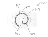
図4は、血液採取装置400の一例を示す。血液採取装置は、取り付け面402と一致する露出面401を有する。取り付け面402の内側には、毛管構造404が埋め込まれている。毛管構造404は、湾曲部406を有する。中心には中心領域408がある。湾曲部406と一致する外側チャネル410が存在する。外側チャネル410は、毛管停止部を形成する。中心領域408を外側チャネル410に接続する5つのスポークチャネル412が示されている。スポークチャネル412が外側チャネル410に合流するところには、鋭利な縁部414が存在する。これらの鋭利な縁部および外側チャネル410は、血液試料を中心領域408およびスポークチャネル412内に留めておくために、毛管停止部を形成する。スポークチャネル412が中心領域408に合流するところには、丸みを帯びた縁部416が存在する。これは、全てのスポークチャネル412および中心領域408の充填を容易にする。血液採取装置400は、可撓性エレメント418に接続される。たとえば、可撓性エレメント418は、カートリッジのカバーに接続され得る。使用中、血液飛沫を伴う指の刺し傷は、おおよそ中心領域408の上に配置されてもよい。スポークチャネル412における毛管作用により、血液は毛管構造404内に引き込まれる。
FIG. 4 shows an example of the
図5は、血液が毛管構造を充填するために用いられた後の血液採取装置400を示す。図5において、中心領域408およびスポークチャネル412は、血液試料500で充填されている。毛管構造の血液500は、血液試料500が充分な量を有するときにそれを示すために、視覚インジケータ502を形成する。血液試料500は、中心領域408およびスポークチャネル412内に留まっていることがわかる。外側チャネル410は血液を含まず、毛管停止部として機能する。
FIG. 5 shows a
図6は、図4および図5に示した血液採取装置400を備えるカートリッジ600の一例を示す。可撓性エレメント418が血液採取装置400をカートリッジ600に接続することがわかる。カートリッジ600は、たとえば、図1~3に示される内部のカートリッジ部分を用いてもよい。測定構造134は、ウィンドウを通して可視である。カートリッジ注入口108は、カートリッジ600の外面602に開口し、露出されたものとして示されている。実際の使用において、被検者は指の刺し傷を有し、その後血液の滴を血液採取装置400上に配置してもよい。図5に示されるように充分な血液が採取されたことが明らかになると、血液採取装置400は、容易にカートリッジ注入口108内に折り畳まれ得る。可撓性エレメント418は、完璧にシールするように血液採取装置400の通路を制御する。いくつかの例においてシールは気密であってもよく、他の例においてシールは気密でなくてもよい。しかしながら、血液採取装置400をカートリッジ注入口108上で閉鎖することにより、血液が跳ねることを防ぐのを補助できる。カートリッジ600のシールは、安全な廃棄をより好都合にもできる。
FIG. 6 shows an example of a
図7は、カートリッジ注入口108上に折り畳まれ閉鎖された後の血液採取装置400を示す。ここでは、カートリッジ注入口108が外面602からシールまたは隔離されていることがわかる。
FIG. 7 shows the
図8、9および10は、血液採取装置800のさらなる例を示す。図8は、血液採取装置800の上部を示す斜視図を示す。図9は、血液採取装置800の下部を示す別の斜視図を示す。図10は、血液採取装置800の底面図を示す。血液採取装置800は、透明な成形プラスチックにより作製される。血液採取装置800は、人間が血液採取装置800を正確に保持することを可能にする指把持部802を備える小さなプラスチック片の形状である。毛管入口403は、下面803を越えて延びる管である。毛管入口403は、血液採取装置800の上部では湾曲した毛管である毛管構造404と接続する。毛管構造404は、大気に対して2つの接続部を有し、一方は毛管入口403、他方は同様に上部にあるベント804である。血液採取装置800は、カートリッジ内にスナップ(snap)されるように構成される。2つの第1のスナップエレメント806が存在する。これらのスナップエレメント806は、カートリッジの外面上のスロット内に嵌合してもよい。スロットは第2のスナップエレメントを形成する。血液採取装置800が表面にスナップされると、血液採取装置800はその後、道具を使わなければ取り外せなくなる。図10において、毛管構造404は、血液試料500で充填されているものとして示される。ベント804は、毛管停止部を形成し、これは毛管構造404を正確な量の血液試料で充填する。
FIGS. 8, 9 and 10 show further examples of the
図8、9および10に示される例に対して様々な変更が行われてもよい。図8、9および10において、毛管入口403は側方にあり、ベント804は血液採取装置800の中心に位置する。代替例では、毛管入口403およびベント804の位置が交換されてもよい。
Various changes may be made to the examples shown in FIGS. 8, 9 and 10. In FIGS. 8, 9 and 10, the
図11は、図8、9および10に示される血液採取装置800を用いる方法を図示する。まずステップ1100において、血液採取装置800の毛管入口403は、指の刺し傷により生じた血液の滴1101と接触させられる。次にステップ1102において、血液採取装置800は、血液試料500が毛管構造全体を充填していることを確かめるために視覚的に検査される。次にステップ1104において、血液採取装置800は、カートリッジ1106上にスナップされる。カートリッジ1106’は、血液採取装置800が取り付けられた状態を示す。第1のスナップエレメント806は、この図においては見えないカートリッジ1106上の溝に入り込む。これにより、血液採取装置800は、カートリッジ1106’に取り外せないように取り付けられる。
FIG. 11 illustrates a method using the
図12および図13は、血液採取装置1200のさらなる例を示す。図12の血液採取装置1200は上面図を示す。図13の図は、斜視側面図を示す。血液採取装置1200は、2つの部分、すなわち、第1の成形部1202および第2の成形部1204から形成される。第1の成形部および/または第2の成形部は、フォイルから作製されてもよい。たとえば、第1の成形部は、熱成形されてもよいプラスチックフォイルから作製されてもよい。第2の成形部は、たとえば、金属またはマイラータイプのフォイルであってもよい。第2の成形部は、いくつかの例においてはフォイル部ともいう。図示される構造は、第1の成形部1202が成形されたプラスチックフォイル由来であるブリスターパックの包装と同様である。これは、後に後面がフォイル1204にシールされる陥凹部を成形部1202に作り出す。血液採取装置1200の中心には、血液採取装置1200の把持および保持を容易にする隆起した指把持部1206がある。第1の成形部1202内には毛管構造404がある。これは、実質的には、隆起した指把持部1206の周りを囲み、湾曲部406を有する毛管チューブである。毛管構造404は、毛管入口403およびベント804を有する。使用において、オペレータは、隆起した指把持部1206によって血液採取装置1200を保持し、毛管入口403を血液または血液製剤と接触させることができる。
12 and 13 show a further example of the
図13は、血液500で充填された毛管構造404を示す。これは、血液試料が完全に採取されたときにそれを示すための視覚インジケータ502を形成する。
FIG. 13 shows a
図14は、血液採取装置1200の使用を視覚的に示す。まず、血液採取装置1200の毛管入口は指の刺し傷の血液の滴1101と接触させられる。次にステップ1402において、血液500が毛管構造404を完全に充填しているかどうかを確認するために、血液採取装置1200は視覚的に検査される。ステップ1404において、血液採取装置1200はカートリッジ1406内に挿入される。カートリッジ1406は、たとえば、血液採取装置1200が配置され得る陥凹部または空間を有してもよい。
FIG. 14 visually illustrates the use of the
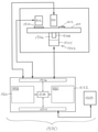
図15は、医療システム1500の一例を示す。医療システム1500は、カートリッジ100を受け取るように構成される。カートリッジ100を回転軸周りで回転させるために動作可能なカートリッジスピナ1502が存在する。カートリッジスピナ1502は、カートリッジの一部1508に付随する把持部1506に取り付けられるモータ1504を有する。カートリッジ100はさらに、測定または透明な構造1510を有するものとして示される。カートリッジ100は、測定構造1510が、たとえば分析物の量の光学的測定を実施できる光学測定システム1512の前になるように回転され得る。この図にはアクチュエータ1511も示されている。これは、カートリッジ100の流体貯蔵部を開放するために用いられ得る。また、カートリッジ上に機械的バルブまたはバルブエレメントが存在する場合にそれらを作動させるために、付加的なアクチュエータまたは機構があってもよい。血液採取装置1513は、カートリッジ100に取り付けられているものとして示される。
FIG. 15 shows an example of the
アクチュエータ1511、カートリッジスピナ1502および測定システム1512は、それら全てが制御装置1514のハードウェアインターフェース1516に接続されているものとして示される。制御装置1514は、ハードウェアインターフェース1516、電子記憶装置1520、電子メモリ1522およびネットワークインターフェース1524と通信するプロセッサ1518を含む。電子メモリ1522は、プロセッサ1518が医療システム1500の動作および機能を制御することを可能にする機械が実行可能な命令を有する。電子記憶装置1520は、プロセッサ1518によって命令1530が実行されて取得された測定結果1532を含むものとして示される。ネットワークインターフェース1524は、プロセッサ1518が、ネットワーク接続1526を介して検査室情報システム1528に測定結果1532を送信することを可能にする。
The
図16は、図15の医療システム1500を動作させる方法を示すフローチャートである。図16のフローチャートは、医療システム1500によって実施されるステップを示す。これらは、血液試料を毛管入口内に配置したり、取り付け面を受け取り面に取り付けたりといったユーザまたはオペレータによって実施されてもよいステップは含まない。
FIG. 16 is a flowchart showing a method of operating the
まずステップ1600において、毛管構造からカートリッジ注入口へ血液試料を搬送するために、カートリッジ100は回転軸周りで回転させられる。次にステップ1602において、カートリッジ注入口からマイクロ流体構造へ血液試料を搬送するために、カートリッジは回転軸周りで回転させられる。次にステップ1604において、マイクロ流体構造を用いて血液試料を処理済の試料へと処理するために、カートリッジの回転は回転軸周りで制御される。次にステップ1606において、カートリッジの回転は、処理済みの試料を測定構造へと移送するために制御される。最後にステップ1608において、分析物の量が測定構造1510および測定システム1512を用いて測定される。
First, in
100 カートリッジ
102 回転軸
104 円形の外縁部
106 平坦な外縁部
108 カートリッジ注入口
110 保管チャンバ
111 マイクロ流体構造
112 拡張チャンバ
112’ 拡張チャンバ
114 ベント
116 フェイルセーフインジケータ
118 血液分離チャンバ
120 オーバーフローチャンバ
122 第1のバルブ構造
124 処理チャンバ
126 試薬用の表面
128 第2のバルブ構造
130 測定構造
132 吸収構造
134 クロマトグラフィーメンブレン
136 流体チャンバ
136’ 流体チャンバ
138 流体ダクト
138’ 流体ダクト
140 計測構造
140’ 計測構造
142 手動の充填位置
144 アリコートチャンバ
146 計測チャンバ
148 接続ダクト
150 流体エレメント
300 カートリッジ
302 流体ダクト
400 血液採取装置
401 露出面
402 取り付け面
403 毛管入口
404 毛管構造
406 湾曲部
408 中心領域
410 外側チャネル(毛管停止部)
412 スポークチャネル
414 鋭利な縁部
416 丸みを帯びた縁部
418 可撓性エレメント
420 取り付け面
500 血液試料
502 視覚インジケータ
600 カートリッジ
602 外面
800 血液採取装置
802 指把持部
803 下面
804 ベント
806 第1のスナップエレメント
1100 毛管入口の指の刺し傷への接触
1101 血液の滴
1102 血液試料の視覚検査
1104 血液採取装置のカートリッジ上へのスナップ
1106 カートリッジ
1106’ 血液採取装置が取り付けられているカートリッジ
1200 血液採取装置
1202 第1の成形部
1204 第2のフォイル部
1206 隆起した指把持部
1400 毛管入口の指の刺し傷への接触
1402 血液試料の視覚検査
1404 血液採取装置のカートリッジ上へのスナップ
1406 カートリッジ
1500 医療システム
1502 カートリッジスピナ
1504 モータ
1506 把持部
1508 カートリッジの一部
1510 測定構造
1511 アクチュエータ
1512 光学測定システム
1513 血液採取装置
1514 制御装置
1516 ハードウェアインターフェース
1518 プロセッサ
1520 電子記憶装置
1522 電子メモリ
1524 ネットワークインターフェース
1526 ネットワーク接続
1528 検査室情報システム
1530 実行可能な命令
1532 測定結果
1600 毛管構造からカートリッジ入口へ血液試料を搬送するために、カートリッジを回転軸周りで回転
1602 カートリッジ入口からマイクロ流体構造へ血液試料を搬送するために、カートリッジを回転軸周りで回転
1604 マイクロ流体構造を用いて血液試料を処理済みの試料へと処理するために、カートリッジの回転軸周りでの回転を制御
1606 処理済みの試料を測定構造へ移送するために、カートリッジの回転を制御
1608 測定構造および測定システムを用いて分析物の量を測定
100
412 Spoke Channel 414 Sharp Edge 416 Rounded Edge 418 Flexible Element 420 Mounting Surface 500 Blood Sample 502 Visual Indicator 600 Cartridge 602 Outer Surface 800 Blood Collection Device 802 Finger Grip 803 Bottom Bottom 804 Vent 806 First Snap Element 1100 Contact with finger sting at the entrance of the capillary 1101 Drops of blood 1102 Visual inspection of blood sample 1104 Snap onto cartridge of blood collection device 1106 Cartridge 1106'Cartridge with blood collection device 1200 Blood collection device 1202 First molding part 1204 Second foil part 1206 Raised finger grip part 1400 Contact with finger sting at the entrance of the capillary 1402 Visual inspection of blood sample 1404 Snap onto cartridge of blood sampling device 1406 Cartridge 1500 Medical system 1502 Cartridge Spinner 1504 Motor 1506 Grip 1508 Part of Cartridge 1510 Measurement Structure 1511 Actuator 1512 Optical Measurement System 1513 Blood Collection Device 1514 Control Device 1516 Hardware Interface 1518 Processor 1520 Electronic Storage Device 1522 Electronic Memory 1524 Network Interface 1526 Network Connection 1528 Laboratory Information system 1530 Executable instructions 1532 Measurement results 1600 Rotate the cartridge around the axis of rotation to transport the blood sample from the capillary structure to the cartridge inlet 1602 To transport the blood sample from the cartridge inlet to the microfluidic structure Rotation around axis of rotation 1604 Controlled rotation of cartridge around axis of rotation to process blood sample into treated sample using microfluidic structure 1606 To transfer treated sample to measurement structure Control cartridge rotation 1608 Measure the amount of analyte using a measurement structure and measurement system
Claims (10)
前記カートリッジは回転軸の周りで回転されるように動作可能であり、
前記血液採取装置は、
取り付け面(402)と、
湾曲部(406)を備える、前記血液試料を保持するための毛管構造(404)と、
前記血液試料を受け取るための毛管入口(403)と
を備え、
前記血液採取装置が、露出面(401)を備え、前記毛管構造が、開放チャネル(408、410、412)として前記露出面に形成され、前記毛管入口が、前記開放チャネルが前記露出面に合流する場所に形成され、前記開放チャネルは、中心領域(408)と、前記中心領域の外側に設けられた外側チャネル(410)と、前記中心領域から放射状に延び、前記中心領域と前記外側チャネルとを接続するスポークチャネル(412)とを備え、前記外側チャネルは、前記スポークチャネル用の毛管停止部を形成し、
前記カートリッジは、
前記取り付け面に取り付けられるための受け取り面と、
前記血液採取装置から前記血液試料を受け取るためのカートリッジ注入口(108)であって、前記血液採取装置は、前記取り付け面が前記受け取り面に取り付けられると前記毛管入口がカートリッジ注入口と流体接続するように構成される、カートリッジ注入口(108)と、
前記カートリッジ注入口に流体接続される、前記血液試料を処理済みの試料へと処理するためのマイクロ流体構造(111)と、
前記血液試料中の前記分析物の量を決定するために、前記処理済みの試料の測定を可能にする測定構造(130)と
を備え、
前記方法は、
前記血液試料を前記毛管入口内に配置すること(1100、1400)と、
前記取り付け面を前記受け取り面に取り付けること(1104、1404)と、
前記毛管構造から前記カートリッジ注入口へ前記血液試料を搬送するために、前記回転軸周りで前記カートリッジを回転させること(1600)と、
前記カートリッジ注入口から前記マイクロ流体構造へ前記血液試料を搬送するために、前記回転軸周りで前記カートリッジを回転させること(1602)と、
前記マイクロ流体構造を用いて前記血液試料を前記処理済みの試料へと処理するために、前記回転軸周りでの前記カートリッジの回転を制御すること(1604)と、
前記処理済みの試料を前記測定構造へ移送するために、前記カートリッジの回転を制御すること(1606)と、
前記測定構造および測定システムを用いて前記分析物の量を測定すること(1608)と
を含む方法。 A method of determining the amount of analyte in a blood sample (500) using a cartridge (100, 300, 600) and a blood sampling device (400, 800, 1200, 1513).
The cartridge is movable to rotate around a axis of rotation.
The blood sampling device is
The mounting surface (402) and
A capillary structure (404) for holding the blood sample, comprising a curved portion (406).
With a capillary inlet (403) for receiving the blood sample,
The blood sampling device comprises an exposed surface (401), the capillary structure is formed on the exposed surface as open channels (408, 410, 412), and the capillary inlet joins the open channel to the exposed surface. The open channel extends radially from the central region (408), the outer channel (410) provided outside the central region, and the central region and the outer channel. The outer channel comprises a spoke channel (412) connecting the spoke channels to form a capillary stop for the spoke channel.
The cartridge is
A receiving surface for mounting on the mounting surface and
A cartridge inlet (108) for receiving the blood sample from the blood sampling device, in which the capillary inlet fluidly connects to the cartridge inlet when the mounting surface is attached to the receiving surface. Cartridge inlet (108), configured as
A microfluidic structure (111) fluidly connected to the cartridge inlet for processing the blood sample into a processed sample.
It comprises a measurement structure (130) that allows measurement of the processed sample to determine the amount of the analyte in the blood sample.
The method is
Placing the blood sample inside the capillary inlet (1100, 1400) and
Attaching the mounting surface to the receiving surface (1104, 1404) and
Rotating the cartridge around the axis of rotation (1600) to transport the blood sample from the capillary structure to the cartridge inlet.
Rotating the cartridge around the axis of rotation (1602) to transport the blood sample from the cartridge inlet to the microfluidic structure.
Controlling the rotation of the cartridge around the axis of rotation in order to process the blood sample into the treated sample using the microfluidic structure (1604).
Controlling the rotation of the cartridge to transfer the processed sample to the measurement structure (1606) and
A method comprising measuring the amount of said analyte using the measuring structure and measuring system (1608).
前記方法がさらに、
前記カートリッジ注入口から前記血液分離チャンバ内へ前記血液試料を搬送するために、前記回転軸周りで前記カートリッジを回転させることと、
遠心分離によって前記血液試料から血漿を分離するために、前記回転軸周りでの前記カートリッジの回転を制御することと
を含み、
前記マイクロ流体構造を用いて前記血液試料を前記処理済みの試料へと処理するために、前記回転軸周りでの前記カートリッジの回転を制御するステップが、前記血漿が前記処理済みの試料へと処理されるように実施される請求項1記載の方法。 The microfluidic structure comprises a blood separation chamber (118) for separating plasma or serum from the blood sample, the blood separation chamber being fluid-connected to the cartridge inlet.
The above method further
Rotating the cartridge around the axis of rotation to transport the blood sample from the cartridge inlet into the blood separation chamber.
Including controlling the rotation of the cartridge around the axis of rotation to separate plasma from the blood sample by centrifugation.
In order to process the blood sample into the treated sample using the microfluidic structure, the step of controlling the rotation of the cartridge around the axis of rotation is to process the plasma into the treated sample. The method according to claim 1, which is carried out so as to be performed.
カートリッジ(100、300、600)の受け取り面に取り付けられるための取り付け面(402)と、
湾曲部(406)を備える、前記血液試料を保持するための毛管構造(404)と、
前記血液試料を前記毛管構造内に受け取るための毛管入口(403)と
を備え、
前記血液採取装置が、露出面(401)を備え、前記毛管構造が、開放チャネル(408、410、412)として前記露出面に形成され、前記毛管入口が、前記開放チャネルが前記露出面に合流する場所に形成され、前記開放チャネルは、中心領域(408)と、前記中心領域の外側に設けられた外側チャネル(410)と、前記中心領域から放射状に延び、前記中心領域と前記外側チャネルとを接続するスポークチャネル(412)とを備え、前記外側チャネルは、前記スポークチャネル用の毛管停止部を形成する医療システム(1500)。 A medical system (1500) including a blood sampling device (400, 800, 1200, 1513) for storing a blood sample (500), wherein the blood sampling device is
A mounting surface (402) for mounting on the receiving surface of the cartridge (100, 300, 600),
A capillary structure (404) for holding the blood sample, comprising a curved portion (406).
It comprises a capillary inlet (403) for receiving the blood sample within the capillary structure.
The blood collection device comprises an exposed surface (401), the capillary structure is formed on the exposed surface as open channels (408, 410, 412), and the capillary inlet is where the open channel joins the exposed surface. The open channel extends radially from the central region (408), the outer channel (410) provided outside the central region, and the central region and the outer channel. A medical system (1500) comprising a spoke channel (412) to connect to, wherein the outer channel forms a capillary stop for the spoke channel .
前記受け取り面と、
前記血液採取装置から前記血液試料を受け取るためのカートリッジ注入口(108)であって、前記血液採取装置は、前記取り付け面が前記受け取り面に取り付けられると前記毛管入口が前記カートリッジ注入口に配置されるように構成される、カートリッジ注入口(108)と、
前記カートリッジ注入口に流体接続される、前記血液試料を処理済みの試料へと処理するためのマイクロ流体構造(111)と、
前記血液試料中の分析物の量を決定するために、前記処理済みの試料の測定を可能にする測定構造(1300)と
を備える請求項4または5記載の医療システム。 The medical system further comprises the cartridge and is capable of operating such that the cartridge is rotated about a rotation axis (102).
The receiving surface and
A cartridge injection port (108) for receiving the blood sample from the blood sampling device, in which the capillary inlet is arranged in the cartridge injection port when the mounting surface is attached to the receiving surface. Cartridge inlet (108), configured to
A microfluidic structure (111) fluidly connected to the cartridge inlet for processing the blood sample into a processed sample.
The medical system of claim 4 or 5 , comprising a measurement structure (1300) that allows measurement of the treated sample to determine the amount of analyte in the blood sample.
前記カートリッジスピナを制御することによって前記毛管構造の前記血液試料をカートリッジ注入口まで搬送するために、前記カートリッジを前記回転軸周りで回転させ(1600)、
前記カートリッジスピナを制御することによって前記カートリッジ注入口からマイクロ流体構造へ前記血液試料を搬送するために、前記カートリッジを前記回転軸周りで回転させ(1602)、
前記カートリッジスピナを制御することによって前記マイクロ流体構造を用いて前記血液試料を処理済みの試料へと処理するために、前記カートリッジの前記回転軸周りでの回転を制御させ(1604)、
前記カートリッジスピナを制御することによって前記処理済みの試料を測定構造へ移送するために、前記カートリッジの回転を制御させ(1606)、
前記測定構造および測定システムを用いて分析物の量を測定させる(1608)
請求項9記載の医療システム。 The medical system includes a memory (1522) for storing instructions (1530) that can be executed by the machine, and a processor (1518) for controlling the medical system, and executes instructions that can be executed by the machine. However, in the processor,
To transport the blood sample of the capillary structure to the cartridge inlet by controlling the cartridge spinner, the cartridge is rotated about the axis of rotation (1600).
To transport the blood sample from the cartridge inlet to the microfluidic structure by controlling the cartridge spinner, the cartridge is rotated about the axis of rotation (1602).
In order to process the blood sample into a treated sample using the microfluidic structure by controlling the cartridge spinner, the rotation of the cartridge around the axis of rotation is controlled (1604).
In order to transfer the processed sample to the measurement structure by controlling the cartridge spinner, the rotation of the cartridge is controlled (1606).
The amount of the analyte is measured using the measurement structure and measurement system (1608).
The medical system according to claim 9 .
Applications Claiming Priority (2)
| Application Number | Priority Date | Filing Date | Title |
|---|---|---|---|
| EP15201585.5A EP3184158B1 (en) | 2015-12-21 | 2015-12-21 | Blood collector with capillary structure |
| EP15201585.5 | 2015-12-21 |
Publications (3)
| Publication Number | Publication Date |
|---|---|
| JP2017116544A JP2017116544A (en) | 2017-06-29 |
| JP2017116544A5 JP2017116544A5 (en) | 2020-01-23 |
| JP7007799B2 true JP7007799B2 (en) | 2022-02-10 |
Family
ID=55129423
Family Applications (1)
| Application Number | Title | Priority Date | Filing Date |
|---|---|---|---|
| JP2016245652A Active JP7007799B2 (en) | 2015-12-21 | 2016-12-19 | Blood sampling device with capillary structure |
Country Status (4)
| Country | Link |
|---|---|
| US (1) | US10416054B2 (en) |
| EP (1) | EP3184158B1 (en) |
| JP (1) | JP7007799B2 (en) |
| KR (1) | KR101923278B1 (en) |
Families Citing this family (10)
| Publication number | Priority date | Publication date | Assignee | Title |
|---|---|---|---|---|
| US11360076B2 (en) | 2012-03-30 | 2022-06-14 | Weavr Health Corp. | Methods and systems to collect a biological sample |
| US11358138B2 (en) | 2013-07-19 | 2022-06-14 | Boston Microfluidics Inc. | Fluid sample collection device |
| USD841186S1 (en) * | 2015-12-23 | 2019-02-19 | Tunghai University | Biochip |
| RU2020117208A (en) | 2017-10-27 | 2021-11-29 | Бостон Майкрофлюидикс, Инк. | LIQUID SAMPLE COLLECTOR |
| US11484877B2 (en) | 2018-05-29 | 2022-11-01 | Weavr Health Corp. | Blood metering device with desiccant and support for storage media and inlay with flange |
| US11772097B2 (en) | 2018-10-19 | 2023-10-03 | Renegadexbio, Pbc | Simultaneous spot test and storage of blood samples |
| GB2595060B (en) | 2018-10-23 | 2022-11-02 | Weavr Health Corp | Funnel with extension tube to augment blood collection device |
| JP2022509817A (en) * | 2018-11-28 | 2022-01-24 | ウィーブル ヘルス コープ. | Simultaneous spot inspection and storage of blood samples |
| CN113841054A (en) * | 2020-04-20 | 2021-12-24 | 利奥碧欧株式会社 | Glycated hemoglobin measurement apparatus and method |
| CN115867386A (en) * | 2020-09-03 | 2023-03-28 | 伊鲁米那有限公司 | Reaction cartridges and related systems and methods |
Citations (6)
| Publication number | Priority date | Publication date | Assignee | Title |
|---|---|---|---|---|
| JP2005283366A (en) | 2004-03-30 | 2005-10-13 | Teiboo Kk | Micro sampling instrument for bodily fluid of living body |
| JP2006068384A (en) | 2004-09-03 | 2006-03-16 | Advance Co Ltd | Body fluid transfer implement, and body fluid inspecting system using the same |
| JP2009128367A (en) | 2007-11-24 | 2009-06-11 | F Hoffmann La Roche Ag | Analytical system and method for analyzing analyte contained in body fluid |
| US20110085950A1 (en) | 2009-10-08 | 2011-04-14 | Samsung Electronics Co., Ltd. | Centrifugal force based microfluidic system and bio cartridge for the microfluidic system |
| JP2014182136A (en) | 2013-03-15 | 2014-09-29 | Ortho-Clinical Diagnostics Inc | Rotatable fluid sample collection device |
| JP2014211349A (en) | 2013-04-18 | 2014-11-13 | ローム株式会社 | Microchip |
Family Cites Families (8)
| Publication number | Priority date | Publication date | Assignee | Title |
|---|---|---|---|---|
| US20030039587A1 (en) * | 2001-08-22 | 2003-02-27 | Volker Niermann | Transfer device |
| EP1916524A1 (en) | 2006-09-27 | 2008-04-30 | Roche Diagnostics GmbH | Rotatable test element |
| EP2072131B1 (en) * | 2007-12-13 | 2015-04-22 | Roche Diagnostics GmbH | Microfluid element for mixing a fluid into a reagent |
| EP2778679B1 (en) * | 2013-03-15 | 2017-09-27 | Ortho-Clinical Diagnostics, Inc. | Rotable disk-shaped fluid sample collection device |
| US10925530B2 (en) * | 2013-04-15 | 2021-02-23 | Becton, Dickinson And Company | Blood sampling transfer device |
| ES2660315T3 (en) * | 2013-04-15 | 2018-03-21 | Becton, Dickinson And Company | Biological fluid extraction device and biological fluid separation system |
| BR112015026139B1 (en) * | 2013-04-15 | 2022-12-06 | Becton, Dickinson And Company | BIOLOGICAL FLUID COLLECTION DEVICE, BIOLOGICAL FLUID SEPARATION DEVICE AND BIOLOGICAL FLUID SEPARATION AND TESTING SYSTEM |
| EP3173149A1 (en) * | 2015-11-26 | 2017-05-31 | Roche Diagnostics GmbH | Determining a quantity of an analyte in a blood sample |
-
2015
- 2015-12-21 EP EP15201585.5A patent/EP3184158B1/en active Active
-
2016
- 2016-12-19 JP JP2016245652A patent/JP7007799B2/en active Active
- 2016-12-19 KR KR1020160173354A patent/KR101923278B1/en active IP Right Grant
- 2016-12-21 US US15/387,007 patent/US10416054B2/en active Active
Patent Citations (6)
| Publication number | Priority date | Publication date | Assignee | Title |
|---|---|---|---|---|
| JP2005283366A (en) | 2004-03-30 | 2005-10-13 | Teiboo Kk | Micro sampling instrument for bodily fluid of living body |
| JP2006068384A (en) | 2004-09-03 | 2006-03-16 | Advance Co Ltd | Body fluid transfer implement, and body fluid inspecting system using the same |
| JP2009128367A (en) | 2007-11-24 | 2009-06-11 | F Hoffmann La Roche Ag | Analytical system and method for analyzing analyte contained in body fluid |
| US20110085950A1 (en) | 2009-10-08 | 2011-04-14 | Samsung Electronics Co., Ltd. | Centrifugal force based microfluidic system and bio cartridge for the microfluidic system |
| JP2014182136A (en) | 2013-03-15 | 2014-09-29 | Ortho-Clinical Diagnostics Inc | Rotatable fluid sample collection device |
| JP2014211349A (en) | 2013-04-18 | 2014-11-13 | ローム株式会社 | Microchip |
Also Published As
| Publication number | Publication date |
|---|---|
| US20170176306A1 (en) | 2017-06-22 |
| JP2017116544A (en) | 2017-06-29 |
| US10416054B2 (en) | 2019-09-17 |
| EP3184158B1 (en) | 2019-01-16 |
| KR20170074189A (en) | 2017-06-29 |
| KR101923278B1 (en) | 2018-11-28 |
| EP3184158A1 (en) | 2017-06-28 |
Similar Documents
| Publication | Publication Date | Title |
|---|---|---|
| JP7007799B2 (en) | Blood sampling device with capillary structure | |
| KR101869184B1 (en) | Rotatable cartridge for measuring a property of a biological sample | |
| US10016758B2 (en) | Rotatable cartridge for analyzing a biological sample | |
| JP6604970B2 (en) | Cartridge with rotatable lid | |
| JP6790081B2 (en) | Determining the amount of sample in a blood sample | |
| US9868120B2 (en) | Rotatable cartridge with a metering chamber for analyzing a biological sample | |
| KR101930611B1 (en) | Rotatable cartridge for processing and analyzing a biological sample | |
| JP2009128367A (en) | Analytical system and method for analyzing analyte contained in body fluid | |
| CN109070078B (en) | Measuring analytes with a cartridge |
Legal Events
| Date | Code | Title | Description |
|---|---|---|---|
| A521 | Request for written amendment filed |
Free format text: JAPANESE INTERMEDIATE CODE: A523 Effective date: 20191206 |
|
| A621 | Written request for application examination |
Free format text: JAPANESE INTERMEDIATE CODE: A621 Effective date: 20191206 |
|
| A977 | Report on retrieval |
Free format text: JAPANESE INTERMEDIATE CODE: A971007 Effective date: 20201028 |
|
| A131 | Notification of reasons for refusal |
Free format text: JAPANESE INTERMEDIATE CODE: A131 Effective date: 20201124 |
|
| A521 | Request for written amendment filed |
Free format text: JAPANESE INTERMEDIATE CODE: A523 Effective date: 20210215 |
|
| A131 | Notification of reasons for refusal |
Free format text: JAPANESE INTERMEDIATE CODE: A131 Effective date: 20210608 |
|
| TRDD | Decision of grant or rejection written | ||
| A01 | Written decision to grant a patent or to grant a registration (utility model) |
Free format text: JAPANESE INTERMEDIATE CODE: A01 Effective date: 20211221 |
|
| A61 | First payment of annual fees (during grant procedure) |
Free format text: JAPANESE INTERMEDIATE CODE: A61 Effective date: 20220107 |
|
| R150 | Certificate of patent or registration of utility model |
Ref document number: 7007799 Country of ref document: JP Free format text: JAPANESE INTERMEDIATE CODE: R150 |