JP6546691B2 - DC heater - Google Patents
DC heater Download PDFInfo
- Publication number
- JP6546691B2 JP6546691B2 JP2018503716A JP2018503716A JP6546691B2 JP 6546691 B2 JP6546691 B2 JP 6546691B2 JP 2018503716 A JP2018503716 A JP 2018503716A JP 2018503716 A JP2018503716 A JP 2018503716A JP 6546691 B2 JP6546691 B2 JP 6546691B2
- Authority
- JP
- Japan
- Prior art keywords
- sheet
- heater
- flexible material
- heating area
- heater according
- Prior art date
- Legal status (The legal status is an assumption and is not a legal conclusion. Google has not performed a legal analysis and makes no representation as to the accuracy of the status listed.)
- Active
Links
Images


Classifications
-
- B—PERFORMING OPERATIONS; TRANSPORTING
- B01—PHYSICAL OR CHEMICAL PROCESSES OR APPARATUS IN GENERAL
- B01L—CHEMICAL OR PHYSICAL LABORATORY APPARATUS FOR GENERAL USE
- B01L3/00—Containers or dishes for laboratory use, e.g. laboratory glassware; Droppers
- B01L3/50—Containers for the purpose of retaining a material to be analysed, e.g. test tubes
- B01L3/508—Containers for the purpose of retaining a material to be analysed, e.g. test tubes rigid containers not provided for above
- B01L3/5082—Test tubes per se
- B01L3/50825—Closing or opening means, corks, bungs
-
- B—PERFORMING OPERATIONS; TRANSPORTING
- B01—PHYSICAL OR CHEMICAL PROCESSES OR APPARATUS IN GENERAL
- B01L—CHEMICAL OR PHYSICAL LABORATORY APPARATUS FOR GENERAL USE
- B01L3/00—Containers or dishes for laboratory use, e.g. laboratory glassware; Droppers
- B01L3/50—Containers for the purpose of retaining a material to be analysed, e.g. test tubes
- B01L3/502—Containers for the purpose of retaining a material to be analysed, e.g. test tubes with fluid transport, e.g. in multi-compartment structures
- B01L3/5027—Containers for the purpose of retaining a material to be analysed, e.g. test tubes with fluid transport, e.g. in multi-compartment structures by integrated microfluidic structures, i.e. dimensions of channels and chambers are such that surface tension forces are important, e.g. lab-on-a-chip
- B01L3/502715—Containers for the purpose of retaining a material to be analysed, e.g. test tubes with fluid transport, e.g. in multi-compartment structures by integrated microfluidic structures, i.e. dimensions of channels and chambers are such that surface tension forces are important, e.g. lab-on-a-chip characterised by interfacing components, e.g. fluidic, electrical, optical or mechanical interfaces
-
- B—PERFORMING OPERATIONS; TRANSPORTING
- B01—PHYSICAL OR CHEMICAL PROCESSES OR APPARATUS IN GENERAL
- B01L—CHEMICAL OR PHYSICAL LABORATORY APPARATUS FOR GENERAL USE
- B01L3/00—Containers or dishes for laboratory use, e.g. laboratory glassware; Droppers
- B01L3/50—Containers for the purpose of retaining a material to be analysed, e.g. test tubes
- B01L3/502—Containers for the purpose of retaining a material to be analysed, e.g. test tubes with fluid transport, e.g. in multi-compartment structures
- B01L3/5027—Containers for the purpose of retaining a material to be analysed, e.g. test tubes with fluid transport, e.g. in multi-compartment structures by integrated microfluidic structures, i.e. dimensions of channels and chambers are such that surface tension forces are important, e.g. lab-on-a-chip
- B01L3/502769—Containers for the purpose of retaining a material to be analysed, e.g. test tubes with fluid transport, e.g. in multi-compartment structures by integrated microfluidic structures, i.e. dimensions of channels and chambers are such that surface tension forces are important, e.g. lab-on-a-chip characterised by multiphase flow arrangements
- B01L3/502784—Containers for the purpose of retaining a material to be analysed, e.g. test tubes with fluid transport, e.g. in multi-compartment structures by integrated microfluidic structures, i.e. dimensions of channels and chambers are such that surface tension forces are important, e.g. lab-on-a-chip characterised by multiphase flow arrangements specially adapted for droplet or plug flow, e.g. digital microfluidics
-
- B—PERFORMING OPERATIONS; TRANSPORTING
- B01—PHYSICAL OR CHEMICAL PROCESSES OR APPARATUS IN GENERAL
- B01L—CHEMICAL OR PHYSICAL LABORATORY APPARATUS FOR GENERAL USE
- B01L3/00—Containers or dishes for laboratory use, e.g. laboratory glassware; Droppers
- B01L3/50—Containers for the purpose of retaining a material to be analysed, e.g. test tubes
- B01L3/505—Containers for the purpose of retaining a material to be analysed, e.g. test tubes flexible containers not provided for above
-
- B—PERFORMING OPERATIONS; TRANSPORTING
- B01—PHYSICAL OR CHEMICAL PROCESSES OR APPARATUS IN GENERAL
- B01L—CHEMICAL OR PHYSICAL LABORATORY APPARATUS FOR GENERAL USE
- B01L3/00—Containers or dishes for laboratory use, e.g. laboratory glassware; Droppers
- B01L3/50—Containers for the purpose of retaining a material to be analysed, e.g. test tubes
- B01L3/508—Containers for the purpose of retaining a material to be analysed, e.g. test tubes rigid containers not provided for above
- B01L3/5085—Containers for the purpose of retaining a material to be analysed, e.g. test tubes rigid containers not provided for above for multiple samples, e.g. microtitration plates
- B01L3/50851—Containers for the purpose of retaining a material to be analysed, e.g. test tubes rigid containers not provided for above for multiple samples, e.g. microtitration plates specially adapted for heating or cooling samples
-
- B—PERFORMING OPERATIONS; TRANSPORTING
- B01—PHYSICAL OR CHEMICAL PROCESSES OR APPARATUS IN GENERAL
- B01L—CHEMICAL OR PHYSICAL LABORATORY APPARATUS FOR GENERAL USE
- B01L3/00—Containers or dishes for laboratory use, e.g. laboratory glassware; Droppers
- B01L3/50—Containers for the purpose of retaining a material to be analysed, e.g. test tubes
- B01L3/508—Containers for the purpose of retaining a material to be analysed, e.g. test tubes rigid containers not provided for above
- B01L3/5085—Containers for the purpose of retaining a material to be analysed, e.g. test tubes rigid containers not provided for above for multiple samples, e.g. microtitration plates
- B01L3/50855—Containers for the purpose of retaining a material to be analysed, e.g. test tubes rigid containers not provided for above for multiple samples, e.g. microtitration plates using modular assemblies of strips or of individual wells
-
- B—PERFORMING OPERATIONS; TRANSPORTING
- B01—PHYSICAL OR CHEMICAL PROCESSES OR APPARATUS IN GENERAL
- B01L—CHEMICAL OR PHYSICAL LABORATORY APPARATUS FOR GENERAL USE
- B01L7/00—Heating or cooling apparatus; Heat insulating devices
- B01L7/52—Heating or cooling apparatus; Heat insulating devices with provision for submitting samples to a predetermined sequence of different temperatures, e.g. for treating nucleic acid samples
-
- H—ELECTRICITY
- H05—ELECTRIC TECHNIQUES NOT OTHERWISE PROVIDED FOR
- H05B—ELECTRIC HEATING; ELECTRIC LIGHT SOURCES NOT OTHERWISE PROVIDED FOR; CIRCUIT ARRANGEMENTS FOR ELECTRIC LIGHT SOURCES, IN GENERAL
- H05B3/00—Ohmic-resistance heating
- H05B3/20—Heating elements having extended surface area substantially in a two-dimensional plane, e.g. plate-heater
- H05B3/22—Heating elements having extended surface area substantially in a two-dimensional plane, e.g. plate-heater non-flexible
- H05B3/26—Heating elements having extended surface area substantially in a two-dimensional plane, e.g. plate-heater non-flexible heating conductor mounted on insulating base
- H05B3/267—Heating elements having extended surface area substantially in a two-dimensional plane, e.g. plate-heater non-flexible heating conductor mounted on insulating base the insulating base being an organic material, e.g. plastic
-
- H—ELECTRICITY
- H05—ELECTRIC TECHNIQUES NOT OTHERWISE PROVIDED FOR
- H05B—ELECTRIC HEATING; ELECTRIC LIGHT SOURCES NOT OTHERWISE PROVIDED FOR; CIRCUIT ARRANGEMENTS FOR ELECTRIC LIGHT SOURCES, IN GENERAL
- H05B3/00—Ohmic-resistance heating
- H05B3/20—Heating elements having extended surface area substantially in a two-dimensional plane, e.g. plate-heater
- H05B3/34—Heating elements having extended surface area substantially in a two-dimensional plane, e.g. plate-heater flexible, e.g. heating nets or webs
-
- B—PERFORMING OPERATIONS; TRANSPORTING
- B01—PHYSICAL OR CHEMICAL PROCESSES OR APPARATUS IN GENERAL
- B01J—CHEMICAL OR PHYSICAL PROCESSES, e.g. CATALYSIS OR COLLOID CHEMISTRY; THEIR RELEVANT APPARATUS
- B01J2219/00—Chemical, physical or physico-chemical processes in general; Their relevant apparatus
- B01J2219/00274—Sequential or parallel reactions; Apparatus and devices for combinatorial chemistry or for making arrays; Chemical library technology
- B01J2219/00277—Apparatus
- B01J2219/00495—Means for heating or cooling the reaction vessels
-
- B—PERFORMING OPERATIONS; TRANSPORTING
- B01—PHYSICAL OR CHEMICAL PROCESSES OR APPARATUS IN GENERAL
- B01J—CHEMICAL OR PHYSICAL PROCESSES, e.g. CATALYSIS OR COLLOID CHEMISTRY; THEIR RELEVANT APPARATUS
- B01J2219/00—Chemical, physical or physico-chemical processes in general; Their relevant apparatus
- B01J2219/00274—Sequential or parallel reactions; Apparatus and devices for combinatorial chemistry or for making arrays; Chemical library technology
- B01J2219/00277—Apparatus
- B01J2219/00497—Features relating to the solid phase supports
- B01J2219/00527—Sheets
- B01J2219/00533—Sheets essentially rectangular
-
- B—PERFORMING OPERATIONS; TRANSPORTING
- B01—PHYSICAL OR CHEMICAL PROCESSES OR APPARATUS IN GENERAL
- B01L—CHEMICAL OR PHYSICAL LABORATORY APPARATUS FOR GENERAL USE
- B01L2300/00—Additional constructional details
- B01L2300/08—Geometry, shape and general structure
- B01L2300/0887—Laminated structure
-
- B—PERFORMING OPERATIONS; TRANSPORTING
- B01—PHYSICAL OR CHEMICAL PROCESSES OR APPARATUS IN GENERAL
- B01L—CHEMICAL OR PHYSICAL LABORATORY APPARATUS FOR GENERAL USE
- B01L2300/00—Additional constructional details
- B01L2300/08—Geometry, shape and general structure
- B01L2300/0893—Geometry, shape and general structure having a very large number of wells, microfabricated wells
-
- B—PERFORMING OPERATIONS; TRANSPORTING
- B01—PHYSICAL OR CHEMICAL PROCESSES OR APPARATUS IN GENERAL
- B01L—CHEMICAL OR PHYSICAL LABORATORY APPARATUS FOR GENERAL USE
- B01L2300/00—Additional constructional details
- B01L2300/08—Geometry, shape and general structure
- B01L2300/0896—Nanoscaled
-
- B—PERFORMING OPERATIONS; TRANSPORTING
- B01—PHYSICAL OR CHEMICAL PROCESSES OR APPARATUS IN GENERAL
- B01L—CHEMICAL OR PHYSICAL LABORATORY APPARATUS FOR GENERAL USE
- B01L2300/00—Additional constructional details
- B01L2300/12—Specific details about materials
- B01L2300/123—Flexible; Elastomeric
-
- B—PERFORMING OPERATIONS; TRANSPORTING
- B01—PHYSICAL OR CHEMICAL PROCESSES OR APPARATUS IN GENERAL
- B01L—CHEMICAL OR PHYSICAL LABORATORY APPARATUS FOR GENERAL USE
- B01L2300/00—Additional constructional details
- B01L2300/18—Means for temperature control
- B01L2300/1805—Conductive heating, heat from thermostatted solids is conducted to receptacles, e.g. heating plates, blocks
- B01L2300/1827—Conductive heating, heat from thermostatted solids is conducted to receptacles, e.g. heating plates, blocks using resistive heater
-
- B—PERFORMING OPERATIONS; TRANSPORTING
- B81—MICROSTRUCTURAL TECHNOLOGY
- B81B—MICROSTRUCTURAL DEVICES OR SYSTEMS, e.g. MICROMECHANICAL DEVICES
- B81B2201/00—Specific applications of microelectromechanical systems
- B81B2201/05—Microfluidics
- B81B2201/058—Microfluidics not provided for in B81B2201/051 - B81B2201/054
-
- B—PERFORMING OPERATIONS; TRANSPORTING
- B81—MICROSTRUCTURAL TECHNOLOGY
- B81B—MICROSTRUCTURAL DEVICES OR SYSTEMS, e.g. MICROMECHANICAL DEVICES
- B81B7/00—Microstructural systems; Auxiliary parts of microstructural devices or systems
- B81B7/0083—Temperature control
-
- H—ELECTRICITY
- H05—ELECTRIC TECHNIQUES NOT OTHERWISE PROVIDED FOR
- H05B—ELECTRIC HEATING; ELECTRIC LIGHT SOURCES NOT OTHERWISE PROVIDED FOR; CIRCUIT ARRANGEMENTS FOR ELECTRIC LIGHT SOURCES, IN GENERAL
- H05B2203/00—Aspects relating to Ohmic resistive heating covered by group H05B3/00
- H05B2203/002—Heaters using a particular layout for the resistive material or resistive elements
- H05B2203/003—Heaters using a particular layout for the resistive material or resistive elements using serpentine layout
Description
本発明は、DC(直流)ヒータおよびその用途に関する。 The present invention relates to DC (direct current) heaters and their applications.
電気ヒータは、一般に、多くの用途で使用されている。しかし、現在のところ、9ボルト以下の電圧を使用して最高で100℃または100℃を超えるまで加熱され得るDCヒータで、1インチ平方以下のサイズのDCヒータは存在しない。このような低電圧源によって電力が供給される小型ヒータは、省スペースおよび節電の点で多くの用途で、特に、携帯用さらには使い捨て用の用途の可能性を開くものである。 Electric heaters are commonly used in many applications. However, at present, DC heaters that can be heated up to over 100 ° C. or more than 100 ° C. using a voltage of 9 volts or less, there is no DC heater of a size of 1 inch square or less. Small heaters powered by such low voltage sources open up the possibility of use in many applications, particularly in portable and disposable applications, in terms of space savings and power savings.
例えば、PCRは、配列決定、疾患診断、DNA試料からの個体の識別、および遺伝子の機能解析のためのDNAクローニングなどの種々の用途でDNA配列の複数のコピーを作成する一般的な方法である。PCRでは、複数の熱サイクルにおいてDNA配列の複製が行われ、各サイクルは、一般に、変性、アニーリングおよび伸長の3つの主要ステップを有する。変性ステップでは、二本鎖DNA鋳型が20〜30秒間で約94〜98℃まで加熱されて、一本鎖DNAが生成される。アニーリングステップでは、20〜40秒間で約50〜65℃まで温度を下げることによりプライマーが一本鎖DNAにアニーリングする。伸長ステップでは、DNAポリメラーゼ(例えば、Taq)を使用して、DNAポリメラーゼの最適な活性温度(Taqの場合、75〜80℃)で一本鎖DNAにアニーリングしたプライマーを伸長することにより、新しい二本鎖DNAを合成する。明らかに、1サイクルにおいて形成された新しい二本鎖DNAが次のサイクルで変性、アニーリング、伸長のステップを受け、各サイクルが得られるDNA配列の数を効果的に2倍生成するので、DNAの複製はかなり指数関数的である。上述した3つの主要ステップ以外に、使用されるDNAポリメラーゼが熱活性化される場合に初期化ステップが必要であり得、一本鎖DNA断片が確実に残ることがないように、長時間にわたって(例えば、5〜15分間)最終サイクルの最終伸長ステップが行われる場合がある。 For example, PCR is a common method of producing multiple copies of DNA sequences in various applications such as sequencing, disease diagnosis, identification of individuals from DNA samples, and DNA cloning for functional analysis of genes. . In PCR, replication of DNA sequences is performed in multiple thermal cycles, and each cycle generally has three major steps: denaturation, annealing and elongation. In the denaturation step, the double stranded DNA template is heated to about 94-98 ° C. for 20-30 seconds to produce single stranded DNA. In the annealing step, the primers are annealed to single-stranded DNA by lowering the temperature to about 50-65 ° C. in 20-40 seconds. In the extension step, two new DNA polymerases (e.g., Taq) are used to extend the primers annealed to single-stranded DNA at the optimal activity temperature (75 to 80 ° C. for Taq) of the DNA polymerase. Synthesize single stranded DNA. Clearly, the new double stranded DNA formed in one cycle is subjected to the steps of denaturation, annealing and extension in the next cycle, so that each cycle effectively doubles the number of DNA sequences obtained, so that The replication is quite exponential. In addition to the three main steps mentioned above, an initialization step may be necessary if the DNA polymerase used is heat activated, and over a long period of time to ensure that no single stranded DNA fragments remain. For example, a final extension step of the final cycle may be performed for 5 to 15 minutes.
したがって、PCRを実施するためのあらゆる装置は、変性、アニーリング、および伸長のステップを行うために反復して熱サイクルを実行することができるものでなければならない。これには、所要温度まで反応物を加熱および冷却して、必要な時間の間、所要温度を維持することが必要である。温度が100℃近くに達する、および/または100℃を超える場合、既存のマイクロ流体またはlab−on−chipPCR装置には、一般的には、必要な熱を供給するための外部サーマルサイクラーが必要であり、このことにより、該装置の使用時の真の可搬性およびサイズを制限することになる。 Thus, any device for performing PCR must be able to perform repeated thermal cycling to perform the steps of denaturation, annealing, and extension. This requires heating and cooling the reaction to the required temperature and maintaining the required temperature for the required time. If the temperature approaches 100 ° C. and / or exceeds 100 ° C., existing microfluidic or lab-on-chip PCR devices generally require an external thermal cycler to supply the necessary heat. This limits the true portability and size of the device in use.
輸血用の血液バッグを温める、またはレトルトパウチとして一般に知られている袋に保存されている食品を単に加熱するなどの他の用途では、現在では一般的に、9ボルトより大幅に高い電圧源を必要とする大型加熱装置が使用されており、使用者にとって可搬性および利便性が制限される。 Other applications, such as warming blood bags for blood transfusion, or simply heating food stored in a bag commonly known as a retort pouch, now generally have a voltage source much higher than 9 volts The large heating devices required are used, which limit the portability and convenience for the user.
第1の態様によれば、非導電性の表面上に配置される熱伝導性材料製の個別加熱領域と、DC電圧源に接続される構造であり、前記DC電圧源に接続されると前記個別加熱領域を均一温度になるまで加熱する構造である少なくとも1つの導電性トレースであって、前記個別加熱領域の周囲の少なくとも一部にわたって前記表面上の波形状部に配置される少なくとも1つの導電性トレースとを備える、DCヒータが提供される。 According to a first aspect, a separate heating region of thermally conductive material disposed on a non-conductive surface, and a structure connected to a DC voltage source, said connection being connected to the DC voltage source At least one conductive trace being a structure for heating a discrete heating area to a uniform temperature, the at least one conductive disposed on the surface over at least a portion of the perimeter of the discrete heating area. A DC heater is provided, comprising a sex trace.
前記DC電圧源は、最大でわずか9ボルトを供給してもよい。 The DC voltage source may supply up to only 9 volts.
前記DC電圧源は、最大でわずか5ボルトを供給してもよい。 The DC voltage source may supply up to only 5 volts.
前記少なくとも1つの導電性トレースは、前記DC電圧源を与えるホストデバイスのUSBポートと接続するためのUSBインターフェースと一体になる構造である端子を備えてもよい。 The at least one conductive trace may comprise a terminal that is configured to be integral with a USB interface for connection to a USB port of a host device providing the DC voltage source.
前記波形状部は、スカラップ状、ノコギリ歯状、波形、矩形波形、ダブテール状、切手の縁の形状、および上述の各波形状部の修正形態から成る群から選択された少なくとも1つの形状であってもよい。 The wave-shaped portion is at least one shape selected from the group consisting of scalloped, saw-toothed, corrugated, rectangular-shaped, dovetailed, shape of the edge of a stamp, and modifications of each wave-shaped portion described above May be
前記表面は、可撓性シート材料上にあってもよい。 The surface may be on a flexible sheet material.
前記DCヒータは、前記表面、前記個別加熱領域、および前記少なくとも1つの導電性トレースの上に設けられる保護層をさらに備えてもよい。 The DC heater may further comprise a protective layer provided on the surface, the discrete heating area, and the at least one conductive trace.
前記個別加熱領域のみが加熱されるアイテムに近接して配置される構造であってもよい。 The structure may be arranged close to the item to which only the individual heating area is heated.
第2の態様によれば、ベースシートと、少なくとも1つの試料捕集開口部および、結果窓として構成される透明部分を有する表面シートと、前記ベースシートと前記表面シートとの間に配設されるPCRチャンバを備えたマイクロ流体チャネルであって、前記少なくとも1つの試料捕集開口部と流体連通する構造であり、前記PCRチャンバの下流側に位置する部分は前記結果窓から見える構造であるマイクロ流体チャネルと、前記個別加熱領域が前記PCRチャンバに近接するように前記ベースシートと前記表面シートとの間に配設される前記第1の態様のDCヒータとを備える、使い捨てPCR装置が提供される。 According to a second aspect, there is provided a base sheet, a top sheet having at least one sample collection opening and a transparent portion configured as a result window, and disposed between the base sheet and the top sheet. A microfluidic channel having a PCR chamber, the structure being in fluid communication with the at least one sample collection opening, the downstream portion of the PCR chamber being a structure visible through the result window A disposable PCR device is provided, comprising: a fluid channel; and the DC heater of the first aspect disposed between the base sheet and the top sheet such that the discrete heating area is close to the PCR chamber. Ru.
前記ベースシート、前記表面シート、および前記マイクロ流体チャネルは、少なくとも1つの可撓性シート材料で形成される。 The base sheet, the face sheet, and the microfluidic channel are formed of at least one flexible sheet material.
第3の態様によれば、製品を保存する構造である電気加熱バッグであって、可撓性材料の第1のシートであって、ポリマー材料の第2のシートに対して封止されることにより前記可撓性材料の第1のシートと前記ポリマー材料の第2のシートとの間に空洞が形成され、前記空洞の周囲に前記可撓性材料の第1のシートと前記可撓性材料の第2のシートとを含む境界を形成する、可撓性材料の第1のシートと、前記第1の態様のDCヒータであって、前記個別加熱領域は前記空洞の第1の壁を形成する前記可撓性材料の第1のシートの部分に配置され、前記少なくとも1つの導電性トレースは前記可撓性材料の第1のシートの前記境界にある前記波形状部内に配置される、DCヒータとを備える電気加熱バッグが提供される。 According to a third aspect, an electrically heated bag, which is a structure for storing products, comprising a first sheet of flexible material sealed against a second sheet of polymeric material A cavity is formed between the first sheet of flexible material and the second sheet of polymeric material, and the first sheet of flexible material and the flexible material around the cavity A first sheet of flexible material forming a boundary including the second sheet of DC and the DC heater of the first aspect, wherein the discrete heating area forms the first wall of the cavity The at least one conductive trace is disposed within the corrugated portion at the boundary of the first sheet of flexible material, the first conductive material being disposed on a portion of the first sheet of flexible material; An electrically heated bag is provided, comprising a heater.
前記電気加熱バッグは、前記空洞と流体連通し、前記製品を分注する構造である閉鎖可能な開口部をさらに備えてもよい。 The electrically heated bag may further comprise a closable opening in fluid communication with the cavity and configured to dispense the product.
前記閉鎖可能な開口部は、チューブに接続可能であり、前記電気加熱バッグは、患者からの血液の採血と保存、および患者への血液または血液製剤の投与のうちの少なくとも1つを行う構造である血液バッグであってもよい。 The closable opening is connectable to a tube, and the electrically heated bag has a structure for performing at least one of blood collection and storage of blood from a patient and administration of a blood or blood product to the patient. It may be a blood bag.
本発明が十分に理解され、容易に実施されるように、単に非限定的な例として、本発明の例示的な実施形態について説明する。まず、添付図面の説明から始める。 Illustrative embodiments of the present invention will be described, merely by way of non-limiting example, in order that the present invention may be well understood and easily implemented. First, we will begin with the description of the attached drawings.
図1〜図5を参照しながら、DCヒータ10の例示的な実施形態およびその種々の用途について後述する。図面では、同じ参照番号は同じ部品または同様の部品を示すのに使用されている。
Exemplary embodiments of the
図1に示されているDCヒータ10の第1の実施形態では、DCヒータ10は、非導電性の表面30上に配置された熱伝導性材料から成る個別加熱領域20を備える。表面30は、例えば、ポリマー材料製としてもよく、比較的硬い材料(例えば、プリント基板に使用されるようなラミネート)または可撓性材料(例えば、可撓性ポリプロピレンシート、ポリマーフィルム、カードストックなど)で形成されてもよい。
In a first embodiment of the
DCヒータ10はさらに、DC電圧源50(図面では、(+)および(−)として示されている)に接続され、DC電圧源50に接続された時に個別加熱領域20を均一温度になるまで加熱する構造である導電性トレース40を備える。個別加熱領域20は、導電性トレース40と導電接触しない。導電性トレース40および個別加熱領域20は、導電性インクまたは適切な金属などの同じ導電性材料から成るのが好ましい。
The
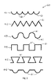
導電性トレース40は、個別加熱領域20の周囲の少なくとも一部にわたって表面30上の波形状部60に配置される。図1では、波形状部60は、図2に示されているように、同じ方向に湾曲し、所定角度で交わり、外側に点を形成し、円弧凸面は個別加熱領域20に向けられた一連の円弧を備えたスカラップ形状41を有する。この実施形態では、個別加熱領域は長方形であり、波形状部60は個別加熱領域20の対向する両側のみに配設される。
The
代替形態では、波形状部60は、図2に示されるように、ノコギリ歯状42、波形43、矩形波形44、ダブテール状45、切手の縁の形状46、または上述の波形状部60のそれぞれの修正形態とすることができる。波形状部60は、導電性トレース40の湾曲または屈曲の反復単位を備えるものと考えられ、そこに直線部分が組み入れられてもよいし、組み入れられなくてもよい。導電性トレース40が湾曲または屈曲する場所の外縁もしくは凸縁または角61で、より高い高温点が生じることが明らかである。したがって、表面30上に導電性トレース40の適切な波形状部60を配設することにより、複数の高温点を個別加熱領域20近くに位置決めすることができる。このようにして、十分な熱が導電性トレース40の波形状部60によって生成され得ることにより、例えば、ラップトップのUSBポートによって供給されるようなわずか5ボルトのDC電圧を使用して、例えば、わずか3mm×10mmの寸法の個別加熱領域20が所望の高い温度になるまで、例えば、100℃以上になるまで加熱されることになる。
In an alternative form, the
DC電圧源50は、DCヒータ10の用途に応じて、9ボルト以下の電圧を有する任意の適切な電源としてもよい。例えば、DC電圧源50は、バッテリの形態としてもよいし、上述したように、ラップトップまたはコンピュータのUSBポートとしてもよいし、自身の電源を有し、5ボルト以下の電圧を有する他のホストデバイスとしてもよい。このようにして、DCヒータ10は、DCヒータ10によって使用される低いDC電圧を供給することができるバッテリまたは他の携帯装置を電力源とすることができるので、持ち運びしやすい。
The
個別加熱領域20を導電性トレース40のどの部分とも接触しないような構造にすることによって、DCヒータ10が定常加熱状態になった時に、個別加熱領域20全体が均一な温度になることが明らかになった。したがって、個別加熱領域20のみが加熱されるアイテムに近接して配置されるようにDCヒータ10を構成することによって、そのアイテムは個別加熱領域20から比較的均一に加熱されることになると思われる。用語「近接して」は、この場合、DCヒータ10の用途に合わせた構造に応じて、アイテムが個別加熱領域20上または個別加熱領域20を覆うように配置される、または個別加熱領域20がアイテムを覆うように配置されるという意味で使用されている。均一に加熱するというこの特徴は、アイテムが熱の影響を受けやすい生物試料または生物学的製剤である生物学的用途では特に重要であり、アイテムのいかなる部分も損傷をもたらし得る過度温度または温度急上昇にさらされないことが重要である。
By configuring the
DCヒータ10はさらに、表面30、個別加熱領域20、および導電性トレース40が環境にさらされることによる損傷から保護するために、これらの上に保護層(図示せず)が設けられるのが好ましい。さらに、保護層は、使用者の安全のために、電気絶縁機能を果たすのが好ましい。
The
上述のDCヒータ10の実用的な用途は、図3に示されているような使い捨てPCR装置100の用途である。PCR装置100は、ベースシート(図示せず)、表面シート101、ベースシートと表面シート101との間に配設されるPCRチャンバ120を備えたマイクロ流体チャネル110、および同様にベースシートと表面シート101との間に配設されるDCヒータ(図示せず)を備える。したがって、ベースシートおよび表面シート101は、PCRチャンバおよびDCヒータを3mm未満の厚さのパッケージの中に収容する。
A practical application of the
表面シート101は、DNA試料を入れるための少なくとも1つの試料捕集開口部102を有する必要があり、PCRチャンバに試薬を加えるための1つまたは複数の他の開口部103を有してもよい。表面シート101はさらに、PCRから得られた結果を見るための結果窓104として構成された透明部分を有する。
The
マイクロ流体チャネルは、DNA試料が装置100のPCRチャンバ120に流入することができるように試料捕集開口部102と流体連通した構造である。マイクロ流体チャネル110の、PCRチャンバ120の下流側にある部分130は、結果窓104から見える構造である。
The microfluidic channel is a structure in fluid communication with the sample collection opening 102 so that the DNA sample can flow into the
使い捨てPCR装置100では、使い捨てPCR装置100内でDCヒータが占めるスペースが極めて小さくなるように、個別加熱領域および導電性トレースはポリマーフィルムなどの薄い可撓性材料製の表面に配置されるのが好ましい。DCヒータは、DCヒータの個別加熱領域のみが装置100内のPCRチャンバ120に近接し、波状部分を含む導電性トレース40はPCRチャンバ120から離間されるように構成される。このようにして、個別加熱領域は、波状部分によって加熱されると均一な熱をPCRチャンバ120に供給するので、装置100内で実行されるPCRに必要な熱サイクルを提供することができる。
In disposable PCR device 100, individual heating areas and conductive traces are placed on a thin, flexible material surface, such as a polymer film, so that the space occupied by the DC heater in disposable PCR device 100 is extremely small. preferable. The DC heater is configured such that only the discrete heating area of the DC heater is proximate to the
使い捨てPCR装置100がUSBホストデバイスによって供給されるDC電圧源を有する必要がある場合、図3に示されているように、PCR装置100はさらに、USBホストデバイスと接続するための、導電性トレース40がUSBインターフェースと一体になる構造であるタブ140を備えてもよい。
If the disposable PCR device 100 needs to have a DC voltage source supplied by a USB host device, as shown in FIG. 3, the PCR device 100 further comprises conductive traces for connection with the USB host device. A
DCヒータ10の別の用途では、図4に示されているように、DCヒータ10は、製品を保存する構造である電気加熱バッグ200上に配置されてもよい。この用途では、電気加熱バッグ200の可撓性材料の第1のシート201が可撓性材料の第2のシート(図示せず)に対して封止されることにより、第1のシート201と第2のシートとの間に空洞202が形成され得る。
In another application of the
この封止は、可撓性材料の第1のシート201と可撓性材料の第2のシートとを含む境界203が、さらに空洞202の周囲に形成されるものでなければならない。DCヒータ10の個別加熱領域20は、空洞202の第1の壁を形成する可撓性材料の第1のシート201の部分204上に配置される。DCヒータ10の導電性トレース40は、可撓性材料の第1のシート201の境界203の波形状部60内に配置される。このようにして、空洞202内に収容されている製品は、導電性トレース40がDC電圧源に接続されると加熱される個別加熱領域20からの熱によって所望の温度まで加熱される。
The seal should be such that a
電気加熱バッグ200の用途が、例えば、バッグ200から分注される製品を保存するものである場合、製品は、消費用の食品または輸血用の血液製剤とすることができ、この場合、バッグ200はさらに、空洞202と流体連通するとともに、製品を分注することができる構造の閉鎖可能な開口部205を有する。バッグ200が患者から血液を採血して保存する、および/または血液もしくは血液製剤を患者に投与するための血液バッグとして使用される特別な場合、閉鎖可能な開口部205はさらに、患者に静脈投与できる構造の端部を有するチューブ(図示せず)に接続できる構造であるのが好ましい。
If the application of the electrically
上記では、本発明の例示的な実施形態に関して説明したが、本発明の範囲から逸脱せずに、設計、構造、および/または操作の細部に多くの変更を加えてもよいことは、当業者は理解するであろう。例えば、必要応じて、DCヒータ10の実際の用途に合わせて、個別加熱領域20および波形状部60の考えられる形状およびサイズを制限することなく、これらの代替形態を備えることも可能である。いくつかの例が図5に示されている。図5(b)に示されているように、DCヒータ10は、個別加熱領域20の周囲に波形状部60を配設するために、1つではなく2つの導電性トレース40を有する。したがって、DCヒータ10内の導電性トレース40の数は、1つまたは複数とすることができる。
Although the foregoing has been described with reference to exemplary embodiments of the present invention, it will be appreciated by those skilled in the art that many changes may be made in the details of design, construction and / or operation without departing from the scope of the present invention. Will understand. For example, if desired, it is possible to provide these alternatives without limiting the possible shapes and sizes of the
Claims (13)
DC電圧源に接続される構造であり、前記DC電圧源に接続されると前記個別加熱領域を均一温度になるまで加熱する構造である少なくとも1つの導電性トレースであって、前記個別加熱領域の周囲の少なくとも一部にわたって前記表面上の波形状部に配置される少なくとも1つの導電性トレースと
を備える、DCヒータ。 Separate heating zones of thermally conductive material arranged on a non-conductive surface,
At least one conductive trace having a structure connected to a DC voltage source, wherein the individual heating area is heated to a uniform temperature when connected to the DC voltage source, wherein A DC heater, comprising: at least one conductive trace disposed in a corrugation on the surface over at least a portion of a perimeter.
少なくとも1つの試料捕集開口部および、結果窓として構成される透明部分を有する表面シートと、
前記ベースシートと前記表面シートとの間に配設されるPCRチャンバを備えたマイクロ流体チャネルであって、前記少なくとも1つの試料捕集開口部と流体連通する構造であり、前記PCRチャンバの下流側に位置する部分は前記結果窓から見える構造であるマイクロ流体チャネルと、
前記個別加熱領域が前記PCRチャンバに近接するように前記ベースシートと前記表面シートとの間に配設される請求項1〜7のうちのいずれか一項に記載のDCヒータと
を備える、使い捨てPCR装置。 Base sheet,
A top sheet having at least one sample collection opening and a transparent part configured as a result window;
A microfluidic channel comprising a PCR chamber disposed between the base sheet and the face sheet, wherein the structure is in fluid communication with the at least one sample collection opening, downstream of the PCR chamber A portion located in the micro-fluid channel which is a structure visible from the result window;
A disposable heater comprising the DC heater according to any one of claims 1 to 7, wherein the individual heating area is disposed between the base sheet and the top sheet so as to be close to the PCR chamber. PCR device.
可撓性材料の第1のシートであって、ポリマー材料の第2のシートに対して封止されることにより前記可撓性材料の第1のシートと前記ポリマー材料の第2のシートとの間に空洞が形成され、前記空洞の周囲に前記可撓性材料の第1のシートと前記可撓性材料の第2のシートとを含む境界を形成する、可撓性材料の第1のシートと、
請求項1〜7のうちのいずれか一項に記載のDCヒータであって、前記個別加熱領域は前記空洞の第1の壁を形成する前記可撓性材料の第1のシートの部分に配置され、前記少なくとも1つの導電性トレースは前記可撓性材料の第1のシートの前記境界にある前記波形状部内に配置される、DCヒータと
を備える電気加熱バッグ。 An electrical heating bag which is a structure for storing a product,
A first sheet of flexible material, sealed with respect to the second sheet of polymeric material, of the first sheet of flexible material and the second sheet of polymeric material A first sheet of flexible material between which a cavity is formed, forming a boundary around the cavity comprising the first sheet of flexible material and the second sheet of flexible material When,
A DC heater according to any one of the preceding claims, wherein the discrete heating area is disposed on a portion of the first sheet of flexible material forming the first wall of the cavity. A DC heater, wherein the at least one conductive trace is disposed within the corrugated portion at the boundary of the first sheet of flexible material.
Applications Claiming Priority (1)
| Application Number | Priority Date | Filing Date | Title |
|---|---|---|---|
| PCT/SG2015/050062 WO2016163946A1 (en) | 2015-04-07 | 2015-04-07 | A dc heater |
Publications (2)
| Publication Number | Publication Date |
|---|---|
| JP2018512721A JP2018512721A (en) | 2018-05-17 |
| JP6546691B2 true JP6546691B2 (en) | 2019-07-17 |
Family
ID=55755648
Family Applications (3)
| Application Number | Title | Priority Date | Filing Date |
|---|---|---|---|
| JP2018503716A Active JP6546691B2 (en) | 2015-04-07 | 2015-04-07 | DC heater |
| JP2017552795A Expired - Fee Related JP6701230B2 (en) | 2015-04-07 | 2016-04-07 | Digital PCR device |
| JP2017552824A Active JP6959866B2 (en) | 2015-04-07 | 2016-04-07 | Fluid tip |
Family Applications After (2)
| Application Number | Title | Priority Date | Filing Date |
|---|---|---|---|
| JP2017552795A Expired - Fee Related JP6701230B2 (en) | 2015-04-07 | 2016-04-07 | Digital PCR device |
| JP2017552824A Active JP6959866B2 (en) | 2015-04-07 | 2016-04-07 | Fluid tip |
Country Status (11)
| Country | Link |
|---|---|
| US (4) | US9999100B2 (en) |
| EP (3) | EP3100587B1 (en) |
| JP (3) | JP6546691B2 (en) |
| KR (1) | KR102385794B1 (en) |
| CN (3) | CN106233818B (en) |
| DK (2) | DK3100587T3 (en) |
| ES (2) | ES2822989T3 (en) |
| PT (2) | PT3100587T (en) |
| SG (1) | SG11201708243RA (en) |
| TW (1) | TWI710280B (en) |
| WO (3) | WO2016163946A1 (en) |
Families Citing this family (6)
| Publication number | Priority date | Publication date | Assignee | Title |
|---|---|---|---|---|
| WO2016163946A1 (en) * | 2015-04-07 | 2016-10-13 | Cell Id Pte Ltd | A dc heater |
| DE102016120124B8 (en) | 2016-10-21 | 2018-08-23 | Gna Biosolutions Gmbh | A method of conducting a polymerase chain reaction and apparatus for carrying out the method |
| US11633549B2 (en) * | 2017-08-28 | 2023-04-25 | Jabil Inc. | Apparatus, system and method of providing a fluid bag heater |
| CN108865821B (en) * | 2018-07-09 | 2021-07-02 | 杭州霆科生物科技有限公司 | Nucleic acid isothermal amplification chip integrated with thermal cracking and use method |
| CN109806921B (en) * | 2019-03-06 | 2021-07-23 | 安徽中医药高等专科学校 | Preparation method of cloth chip and cloth chip |
| CN111056525B (en) * | 2019-11-12 | 2023-04-18 | 重庆大学 | Method for enhancing boiling heat exchange of micro-channel and inhibiting flow instability caused by alternating current infiltration effect |
Family Cites Families (51)
| Publication number | Priority date | Publication date | Assignee | Title |
|---|---|---|---|---|
| JPS5220774A (en) | 1975-08-08 | 1977-02-16 | Matsushita Electric Ind Co Ltd | Manufacturing method of variable capacitance element |
| FR2634892B1 (en) * | 1988-07-28 | 1990-09-14 | Guigan Jean | DEVICE FOR PERFORMING BIOLOGICAL ANALYSIS BY IMMUNO-ENZYMATIC DETECTION OF ANTIBODIES OR ANTIGENS IN A SERUM |
| JP3220229B2 (en) * | 1992-05-26 | 2001-10-22 | テルモ株式会社 | Heating element for tube connection device and method of manufacturing the same |
| US6399023B1 (en) | 1996-04-16 | 2002-06-04 | Caliper Technologies Corp. | Analytical system and method |
| FR2765967B1 (en) * | 1997-07-11 | 1999-08-20 | Commissariat Energie Atomique | CHIP ANALYSIS DEVICE COMPRISING LOCALIZED HEATING ELECTRODES |
| WO2000036880A2 (en) * | 1998-12-17 | 2000-06-22 | Personal Chemistry I Uppsala Ab | Microwave apparatus and methods for performing chemical reactions |
| US6533255B1 (en) | 1999-05-14 | 2003-03-18 | Hitachi Chemical Research Center, Inc. | Liquid metal-heating apparatus for biological/chemical sample |
| US6939451B2 (en) * | 2000-09-19 | 2005-09-06 | Aclara Biosciences, Inc. | Microfluidic chip having integrated electrodes |
| US7238325B2 (en) * | 2000-09-22 | 2007-07-03 | Kawamura Institute Of Chemical Research | Very small chemical device and flow rate adjusting method therefor |
| US7216660B2 (en) * | 2000-11-02 | 2007-05-15 | Princeton University | Method and device for controlling liquid flow on the surface of a microfluidic chip |
| US6586233B2 (en) * | 2001-03-09 | 2003-07-01 | The Regents Of The University Of California | Convectively driven PCR thermal-cycling |
| US6852287B2 (en) * | 2001-09-12 | 2005-02-08 | Handylab, Inc. | Microfluidic devices having a reduced number of input and output connections |
| US6706004B2 (en) | 2001-05-31 | 2004-03-16 | Infraredx, Inc. | Balloon catheter |
| US6750661B2 (en) | 2001-11-13 | 2004-06-15 | Caliper Life Sciences, Inc. | Method and apparatus for controllably effecting samples using two signals |
| JP2003323219A (en) * | 2002-01-22 | 2003-11-14 | Thermo Solution:Kk | Temperature regulator |
| US6847018B2 (en) | 2002-02-26 | 2005-01-25 | Chon Meng Wong | Flexible heating elements with patterned heating zones for heating of contoured objects powered by dual AC and DC voltage sources without transformer |
| DE60228685D1 (en) * | 2002-05-16 | 2008-10-16 | Micronit Microfluidics Bv | Method for producing a microfluidic component |
| JP2004031147A (en) * | 2002-06-26 | 2004-01-29 | Nippon Valqua Ind Ltd | Glass panel for cathode-ray tube |
| US6955725B2 (en) * | 2002-08-15 | 2005-10-18 | Micron Technology, Inc. | Reactors with isolated gas connectors and methods for depositing materials onto micro-device workpieces |
| US7049558B2 (en) | 2003-01-27 | 2006-05-23 | Arcturas Bioscience, Inc. | Apparatus and method for heating microfluidic volumes and moving fluids |
| JP4482684B2 (en) * | 2004-01-29 | 2010-06-16 | Biocosm株式会社 | Microfluidic device temperature controller |
| KR100577406B1 (en) * | 2003-09-17 | 2006-05-10 | 박재상 | Heater and the method for producing the same using pcb |
| JP5502275B2 (en) * | 2004-05-02 | 2014-05-28 | フルイディグム コーポレイション | Thermal reaction device and method of using the thermal reaction device |
| DE102005052713A1 (en) | 2005-11-04 | 2007-05-16 | Clondiag Chip Tech Gmbh | Apparatus and method for detecting molecular interactions |
| US8936945B2 (en) * | 2005-11-17 | 2015-01-20 | The Regents Of The University Of Michigan | Compositions and methods for liquid metering in microchannels |
| KR100768089B1 (en) * | 2005-11-30 | 2007-10-18 | 한국전자통신연구원 | Affirnity Chromatography microdevice, and preparing method of the same |
| JPWO2007099736A1 (en) * | 2006-03-03 | 2009-07-16 | コニカミノルタエムジー株式会社 | Micro inspection chip, optical detection device, and micro total analysis system |
| EP1878502A1 (en) * | 2006-07-14 | 2008-01-16 | Roche Diagnostics GmbH | Instrument for heating and cooling |
| US8008606B2 (en) * | 2006-10-04 | 2011-08-30 | T-Ink, Inc. | Composite heating element with an integrated switch |
| JP2008151771A (en) * | 2006-11-22 | 2008-07-03 | Fujifilm Corp | Micro fluid chip |
| US20080153152A1 (en) | 2006-11-22 | 2008-06-26 | Akira Wakabayashi | Microfluidic chip |
| EP2610007B1 (en) * | 2007-07-23 | 2018-12-05 | CLONDIAG GmbH | Assays |
| WO2009020435A1 (en) * | 2007-08-07 | 2009-02-12 | Agency For Science, Technology And Research | Integrated microfluidic device for gene synthesis |
| WO2009019658A2 (en) | 2007-08-09 | 2009-02-12 | Koninklijke Philips Electronics N.V. | Integrated microfluidic device with local temperature control |
| JP2009119386A (en) * | 2007-11-15 | 2009-06-04 | Fujifilm Corp | Microfluid chip and liquid mixing method using it |
| US9551026B2 (en) | 2007-12-03 | 2017-01-24 | Complete Genomincs, Inc. | Method for nucleic acid detection using voltage enhancement |
| KR101465701B1 (en) | 2008-01-22 | 2014-11-28 | 삼성전자 주식회사 | Apparatus for amplifying nucleic acids |
| JP5326117B2 (en) | 2008-08-25 | 2013-10-30 | 株式会社AMBiS | Antifoaming device, culture system and container with antifoaming device |
| GB0919159D0 (en) * | 2009-11-02 | 2009-12-16 | Sec Dep For Environment Food A | Device and apparatus |
| WO2013103360A1 (en) | 2011-02-25 | 2013-07-11 | The Trustees Of The University Of Pennsylvania | Isothermal nucleic acid amplification reactor with integrated solid state membrane |
| BR112013022889B8 (en) * | 2011-03-08 | 2022-12-20 | Univ Laval | CENTRIPETAL FLUIDIC DEVICE FOR TESTING COMPONENTS OF A BIOLOGICAL MATERIAL IN A FLUID, TEST APPARATUS AND TESTING METHOD USING SUCH CENTRIPETAL FLUIDIC DEVICE |
| US20130137144A1 (en) * | 2011-06-08 | 2013-05-30 | Bio-Rad Laboratories, Inc. LSG - GXD Division | Thermal block with built-in thermoelectric elements |
| CN103732760A (en) * | 2011-09-23 | 2014-04-16 | 纽约市哥伦比亚大学理事会 | Isolation and enrichment of nucleic acids on microchip |
| AU2011226954A1 (en) * | 2011-09-29 | 2013-04-18 | Skaffold Pty Limited | Systems and methods for providing share assessment data with compound quality analysis |
| JP6001418B2 (en) * | 2012-11-02 | 2016-10-05 | パナソニックヘルスケアホールディングス株式会社 | Processing chip for biochemical analysis |
| WO2013172003A1 (en) | 2012-05-16 | 2013-11-21 | パナソニック株式会社 | Organism detection chip and organism detection device provided therewith |
| EP2901129A4 (en) * | 2012-09-26 | 2016-11-02 | Ibis Biosciences Inc | Swab interface for a microfluidic device |
| CN104755433A (en) | 2012-09-28 | 2015-07-01 | 专业净化有限公司 | Residual disinfection of water |
| DE102012219656A1 (en) | 2012-10-26 | 2014-04-30 | Fraunhofer-Gesellschaft zur Förderung der angewandten Forschung e.V. | SYSTEM FOR CARRYING OUT TOUCH-FREE MEASUREMENT ON A SAMPLE AND SAMPLE CARRIER |
| JP6086478B2 (en) * | 2013-01-28 | 2017-03-01 | 国立研究開発法人産業技術総合研究所 | Surface heater and device using the same |
| WO2016163946A1 (en) * | 2015-04-07 | 2016-10-13 | Cell Id Pte Ltd | A dc heater |
-
2015
- 2015-04-07 WO PCT/SG2015/050062 patent/WO2016163946A1/en active Application Filing
- 2015-04-07 KR KR1020157033265A patent/KR102385794B1/en active IP Right Grant
- 2015-04-07 ES ES15788314T patent/ES2822989T3/en active Active
- 2015-04-07 PT PT157883141T patent/PT3100587T/en unknown
- 2015-04-07 JP JP2018503716A patent/JP6546691B2/en active Active
- 2015-04-07 EP EP15788314.1A patent/EP3100587B1/en active Active
- 2015-04-07 CN CN201580001017.1A patent/CN106233818B/en not_active Expired - Fee Related
- 2015-04-07 US US14/893,002 patent/US9999100B2/en active Active
- 2015-04-07 SG SG11201708243RA patent/SG11201708243RA/en unknown
- 2015-04-07 DK DK15788314.1T patent/DK3100587T3/en active
- 2015-11-12 TW TW104137376A patent/TWI710280B/en active
-
2016
- 2016-04-07 WO PCT/SG2016/050171 patent/WO2016163956A1/en active Search and Examination
- 2016-04-07 JP JP2017552795A patent/JP6701230B2/en not_active Expired - Fee Related
- 2016-04-07 CN CN201680028284.2A patent/CN107921431B/en not_active Expired - Fee Related
- 2016-04-07 EP EP16716937.4A patent/EP3110553A1/en not_active Withdrawn
- 2016-04-07 DK DK16717490.3T patent/DK3110554T3/en active
- 2016-04-07 CN CN201680028255.6A patent/CN107847931B/en not_active Expired - Fee Related
- 2016-04-07 PT PT167174903T patent/PT3110554T/en unknown
- 2016-04-07 EP EP16717490.3A patent/EP3110554B1/en active Active
- 2016-04-07 ES ES16717490T patent/ES2868782T3/en active Active
- 2016-04-07 JP JP2017552824A patent/JP6959866B2/en active Active
- 2016-04-07 WO PCT/SG2016/050172 patent/WO2016163957A1/en active Search and Examination
-
2017
- 2017-10-07 US US15/727,589 patent/US10638547B2/en active Active
- 2017-10-07 US US15/727,588 patent/US10750577B2/en active Active
-
2020
- 2020-06-11 US US16/899,346 patent/US11477857B2/en active Active
Also Published As
Similar Documents
| Publication | Publication Date | Title |
|---|---|---|
| JP6546691B2 (en) | DC heater | |
| WO2014089000A3 (en) | Temperature controlling surfaces and support structures | |
| WO2008035074A3 (en) | Improvements in reaction apparatus | |
| JP6858368B2 (en) | Thermal cycler | |
| CN201940242U (en) | Heating device for water bath | |
| JP6140015B2 (en) | Heat storage | |
| JP2021108668A (en) | Temperature control device | |
| US20230166265A1 (en) | Integrated solid-state rapid thermo-cycling system | |
| WO2009054081A1 (en) | Heat-storage perspiration device | |
| CN203735654U (en) | Eyelash curler | |
| JP2019107199A (en) | Medicament permeation device | |
| JP2011212374A (en) | Moxibustion device | |
| CN102743004A (en) | Negative ion emitting device for hair straightening device | |
| TR201510348A2 (en) | CENTRAL HEATED WAX SYSTEM |
Legal Events
| Date | Code | Title | Description |
|---|---|---|---|
| A621 | Written request for application examination |
Free format text: JAPANESE INTERMEDIATE CODE: A621 Effective date: 20180403 |
|
| TRDD | Decision of grant or rejection written | ||
| A01 | Written decision to grant a patent or to grant a registration (utility model) |
Free format text: JAPANESE INTERMEDIATE CODE: A01 Effective date: 20190528 |
|
| A61 | First payment of annual fees (during grant procedure) |
Free format text: JAPANESE INTERMEDIATE CODE: A61 Effective date: 20190621 |
|
| R150 | Certificate of patent or registration of utility model |
Ref document number: 6546691 Country of ref document: JP Free format text: JAPANESE INTERMEDIATE CODE: R150 |
|
| R250 | Receipt of annual fees |
Free format text: JAPANESE INTERMEDIATE CODE: R250 |
|
| R250 | Receipt of annual fees |
Free format text: JAPANESE INTERMEDIATE CODE: R250 |