JP6541671B2 - Receiver with variable geometry for clean water by UV - Google Patents
Receiver with variable geometry for clean water by UV Download PDFInfo
- Publication number
- JP6541671B2 JP6541671B2 JP2016550708A JP2016550708A JP6541671B2 JP 6541671 B2 JP6541671 B2 JP 6541671B2 JP 2016550708 A JP2016550708 A JP 2016550708A JP 2016550708 A JP2016550708 A JP 2016550708A JP 6541671 B2 JP6541671 B2 JP 6541671B2
- Authority
- JP
- Japan
- Prior art keywords
- fluid
- chamber
- adjustable wall
- wall
- adjustable
- Prior art date
- Legal status (The legal status is an assumption and is not a legal conclusion. Google has not performed a legal analysis and makes no representation as to the accuracy of the status listed.)
- Expired - Fee Related
Links
- XLYOFNOQVPJJNP-UHFFFAOYSA-N water Substances O XLYOFNOQVPJJNP-UHFFFAOYSA-N 0.000 title description 5
- 239000012530 fluid Substances 0.000 claims description 244
- 230000005855 radiation Effects 0.000 claims description 61
- 230000001954 sterilising effect Effects 0.000 claims description 54
- 238000004659 sterilization and disinfection Methods 0.000 claims description 49
- 239000000463 material Substances 0.000 claims description 12
- 238000000034 method Methods 0.000 claims description 9
- 230000005540 biological transmission Effects 0.000 claims description 6
- 239000010453 quartz Substances 0.000 claims description 4
- VYPSYNLAJGMNEJ-UHFFFAOYSA-N silicon dioxide Inorganic materials O=[Si]=O VYPSYNLAJGMNEJ-UHFFFAOYSA-N 0.000 claims description 4
- 230000003247 decreasing effect Effects 0.000 claims description 2
- 108020004414 DNA Proteins 0.000 description 6
- RWQNBRDOKXIBIV-UHFFFAOYSA-N thymine Chemical compound CC1=CNC(=O)NC1=O RWQNBRDOKXIBIV-UHFFFAOYSA-N 0.000 description 6
- 230000008901 benefit Effects 0.000 description 4
- 244000005700 microbiome Species 0.000 description 4
- 230000007246 mechanism Effects 0.000 description 3
- 238000012545 processing Methods 0.000 description 3
- 229940113082 thymine Drugs 0.000 description 3
- 241000894006 Bacteria Species 0.000 description 2
- 108020000946 Bacterial DNA Proteins 0.000 description 2
- 102000053602 DNA Human genes 0.000 description 2
- 238000010521 absorption reaction Methods 0.000 description 2
- XAGFODPZIPBFFR-UHFFFAOYSA-N aluminium Chemical compound [Al] XAGFODPZIPBFFR-UHFFFAOYSA-N 0.000 description 2
- 229910052782 aluminium Inorganic materials 0.000 description 2
- 238000004364 calculation method Methods 0.000 description 2
- 239000010949 copper Substances 0.000 description 2
- 239000010931 gold Substances 0.000 description 2
- 230000035772 mutation Effects 0.000 description 2
- 238000002310 reflectometry Methods 0.000 description 2
- 239000010948 rhodium Substances 0.000 description 2
- 239000010936 titanium Substances 0.000 description 2
- 238000009827 uniform distribution Methods 0.000 description 2
- RYGMFSIKBFXOCR-UHFFFAOYSA-N Copper Chemical compound [Cu] RYGMFSIKBFXOCR-UHFFFAOYSA-N 0.000 description 1
- 241000223935 Cryptosporidium Species 0.000 description 1
- 102000004190 Enzymes Human genes 0.000 description 1
- 108090000790 Enzymes Proteins 0.000 description 1
- 241000224466 Giardia Species 0.000 description 1
- BQCADISMDOOEFD-UHFFFAOYSA-N Silver Chemical compound [Ag] BQCADISMDOOEFD-UHFFFAOYSA-N 0.000 description 1
- RTAQQCXQSZGOHL-UHFFFAOYSA-N Titanium Chemical compound [Ti] RTAQQCXQSZGOHL-UHFFFAOYSA-N 0.000 description 1
- 108020005202 Viral DNA Proteins 0.000 description 1
- 241000700605 Viruses Species 0.000 description 1
- 230000009471 action Effects 0.000 description 1
- 230000001580 bacterial effect Effects 0.000 description 1
- 230000000903 blocking effect Effects 0.000 description 1
- 238000009395 breeding Methods 0.000 description 1
- 230000001488 breeding effect Effects 0.000 description 1
- 238000001311 chemical methods and process Methods 0.000 description 1
- 238000005660 chlorination reaction Methods 0.000 description 1
- 229910052802 copper Inorganic materials 0.000 description 1
- 238000005336 cracking Methods 0.000 description 1
- 238000013461 design Methods 0.000 description 1
- 230000001627 detrimental effect Effects 0.000 description 1
- 239000000539 dimer Substances 0.000 description 1
- 238000001914 filtration Methods 0.000 description 1
- 231100000722 genetic damage Toxicity 0.000 description 1
- PCHJSUWPFVWCPO-UHFFFAOYSA-N gold Chemical compound [Au] PCHJSUWPFVWCPO-UHFFFAOYSA-N 0.000 description 1
- 229910052737 gold Inorganic materials 0.000 description 1
- 230000036541 health Effects 0.000 description 1
- 238000005286 illumination Methods 0.000 description 1
- 230000000415 inactivating effect Effects 0.000 description 1
- 230000002779 inactivation Effects 0.000 description 1
- 238000009434 installation Methods 0.000 description 1
- 230000001678 irradiating effect Effects 0.000 description 1
- 238000012423 maintenance Methods 0.000 description 1
- 238000007726 management method Methods 0.000 description 1
- 238000005259 measurement Methods 0.000 description 1
- QSHDDOUJBYECFT-UHFFFAOYSA-N mercury Chemical compound [Hg] QSHDDOUJBYECFT-UHFFFAOYSA-N 0.000 description 1
- 229910052753 mercury Inorganic materials 0.000 description 1
- 239000003471 mutagenic agent Substances 0.000 description 1
- 231100000707 mutagenic chemical Toxicity 0.000 description 1
- 230000003505 mutagenic effect Effects 0.000 description 1
- 244000052769 pathogen Species 0.000 description 1
- 230000008569 process Effects 0.000 description 1
- 230000009467 reduction Effects 0.000 description 1
- 238000009877 rendering Methods 0.000 description 1
- 230000003362 replicative effect Effects 0.000 description 1
- 229910052703 rhodium Inorganic materials 0.000 description 1
- MHOVAHRLVXNVSD-UHFFFAOYSA-N rhodium atom Chemical compound [Rh] MHOVAHRLVXNVSD-UHFFFAOYSA-N 0.000 description 1
- 230000035939 shock Effects 0.000 description 1
- 229910052709 silver Inorganic materials 0.000 description 1
- 239000004332 silver Substances 0.000 description 1
- 239000007787 solid Substances 0.000 description 1
- 230000007480 spreading Effects 0.000 description 1
- 238000003892 spreading Methods 0.000 description 1
- 239000000126 substance Substances 0.000 description 1
- 239000000758 substrate Substances 0.000 description 1
- 229910052719 titanium Inorganic materials 0.000 description 1
- 238000002834 transmittance Methods 0.000 description 1
- 230000003612 virological effect Effects 0.000 description 1
- 239000002699 waste material Substances 0.000 description 1
- 238000005303 weighing Methods 0.000 description 1
Images


Classifications
-
- C—CHEMISTRY; METALLURGY
- C02—TREATMENT OF WATER, WASTE WATER, SEWAGE, OR SLUDGE
- C02F—TREATMENT OF WATER, WASTE WATER, SEWAGE, OR SLUDGE
- C02F1/00—Treatment of water, waste water, or sewage
- C02F1/30—Treatment of water, waste water, or sewage by irradiation
- C02F1/32—Treatment of water, waste water, or sewage by irradiation with ultraviolet light
- C02F1/325—Irradiation devices or lamp constructions
-
- C—CHEMISTRY; METALLURGY
- C02—TREATMENT OF WATER, WASTE WATER, SEWAGE, OR SLUDGE
- C02F—TREATMENT OF WATER, WASTE WATER, SEWAGE, OR SLUDGE
- C02F1/00—Treatment of water, waste water, or sewage
- C02F1/008—Control or steering systems not provided for elsewhere in subclass C02F
-
- C—CHEMISTRY; METALLURGY
- C02—TREATMENT OF WATER, WASTE WATER, SEWAGE, OR SLUDGE
- C02F—TREATMENT OF WATER, WASTE WATER, SEWAGE, OR SLUDGE
- C02F2201/00—Apparatus for treatment of water, waste water or sewage
- C02F2201/32—Details relating to UV-irradiation devices
- C02F2201/322—Lamp arrangement
- C02F2201/3221—Lamps suspended above a water surface or pipe
-
- C—CHEMISTRY; METALLURGY
- C02—TREATMENT OF WATER, WASTE WATER, SEWAGE, OR SLUDGE
- C02F—TREATMENT OF WATER, WASTE WATER, SEWAGE, OR SLUDGE
- C02F2201/00—Apparatus for treatment of water, waste water or sewage
- C02F2201/32—Details relating to UV-irradiation devices
- C02F2201/322—Lamp arrangement
- C02F2201/3228—Units having reflectors, e.g. coatings, baffles, plates, mirrors
-
- C—CHEMISTRY; METALLURGY
- C02—TREATMENT OF WATER, WASTE WATER, SEWAGE, OR SLUDGE
- C02F—TREATMENT OF WATER, WASTE WATER, SEWAGE, OR SLUDGE
- C02F2303/00—Specific treatment goals
- C02F2303/04—Disinfection
Description
本発明は、流体殺菌の分野に関し、より詳細には、UV LEDによる流体殺菌に関する。 The present invention relates to the field of fluid sterilization, and more particularly to fluid sterilization with UV LEDs.
より少ない有害なバクテリアを含む流体を提供するための流体殺菌の重要性は、広く認識されている。対象の流体が、例えばヒト又は動物が摂取するために準備されている水であるとき、上記の認識はより先見の明があるものとなる。 The importance of fluid sterilization to provide fluids containing less harmful bacteria is widely recognized. When the fluid of interest is, for example, water being prepared for human or animal consumption, the above recognition is more foresighted.
UV放射を用いた流体殺菌は、1980年代に初めて使用された。これは、特に流体が体内摂取用の水であるときに、塩素殺菌等の他の方法に勝る多くの利点を有する。UV放射は、殺菌された流体のPH、組成、味、又は匂いに影響を及ぼさない。流体の殺菌は、バクテリア、ウイルス、及び細菌のDNAを不活性化することによって実現される。流体を殺菌するためのUVの使用の更なる利点は、単純な設置、より少ないメンテナンスの必要性、及び空間効率である。更に、流体を処理するためのUVの使用は、化学的プロセスの使用の必要性をなくし、それにより、殺菌完了後の流体に化学的な匂い又は味が生じる可能性をなくす。 Fluid sterilization using UV radiation was first used in the 1980's. This has many advantages over other methods such as chlorination, especially when the fluid is water for internal consumption. UV radiation does not affect the pH, composition, taste or smell of the sterilized fluid. Disinfection of the fluid is achieved by inactivating bacterial, viral and bacterial DNA. Further advantages of the use of UV to sterilize the fluid are simple installation, less maintenance requirements and space efficiency. Furthermore, the use of UV to process the fluid eliminates the need for the use of chemical processes, thereby eliminating the possibility of chemical odor or taste in the fluid after sterilization is complete.
現在のUVによる水殺菌技術は、主に、水を殺菌するUV放射を提供するために、水銀放電ランプを使用する。一般に、これらのシステムは、システムを通って流れる流体にUV放射を提供する。 Current UV water sterilization techniques primarily use mercury discharge lamps to provide UV radiation to sterilize water. Generally, these systems provide UV radiation to the fluid flowing through the system.
米国特許第7520978号は、流体中に存在する微生物を不活性化するために、紫外(UV:ultra violet)光を使用して流体を浄化するためのシステムを開示する。このシステムは、穿孔プレート上にUV光放出器の配置を有する。流体は、穿孔プレートの穿孔を通過する間、UV光放出器によって放出されるUV光に露出される。流体中に存在する微生物は、UV光放出器の非常に近くを通る。微生物によって吸収されるUV光が、遺伝子の損傷及び不活性化を引き起こす。システムは、UV光放出器に電力を供給する電源ユニットに、流体の物理的特性に関するフィードバックを提供するフィードバックユニットを有する。電源ユニットは、フィードバックに基づいて、UV光放出器に供給される電力の量を変える。 U.S. Pat. No. 7,520,978 discloses a system for purifying fluids using ultra violet (UV) light to deactivate microorganisms present in the fluid. This system has an arrangement of UV light emitters on a perforated plate. The fluid is exposed to the UV light emitted by the UV light emitter while passing through the perforations of the perforated plate. The microorganisms present in the fluid pass very close to the UV light emitter. UV light absorbed by microorganisms causes genetic damage and inactivation. The system has a feedback unit that provides feedback on the physical characteristics of the fluid to a power supply unit that supplies power to the UV light emitter. The power supply unit changes the amount of power supplied to the UV light emitter based on the feedback.
紫外(UV)放射は、細菌のDNAを破壊し、それにより繁殖を防止する。繁殖しなければ、微生物は、健康への危険がはるかに少なくなる。従って、UV放射は突然変異原であり、即ち、UV放射は、DNAの構造内部で突然変異を生み出す。100〜280nmの短波長範囲内のUV−C放射は、DNA中の4つの核酸塩基の1つであるチミンに作用する。DNA鎖内部の別のチミンに隣接するチミン分子によってUV光子が吸収されるとき、分子間の共有結合又は二量体が形成され得、これは、DNAの通常の構造とは異なる(通常の構造では、塩基は、対向するDNA鎖にある同じパートナと常に対を成している)。これにより、2つの塩基間にバルジが生じ、バルジは、酵素がDNAを「解読」して複製するのを防止し、それにより細菌の生殖能力をなくす。 Ultraviolet (UV) radiation destroys bacterial DNA, thereby preventing reproduction. Without breeding, microbes have much less of a health risk. Thus, UV radiation is a mutagen, ie UV radiation produces a mutation within the structure of DNA. UV-C radiation in the short wavelength range of 100-280 nm acts on thymine, one of four nucleobases in DNA. When a UV photon is absorbed by a thymine molecule adjacent to another thymine inside a DNA strand, a covalent bond or dimer may be formed between the molecules, which is different from the normal structure of DNA (normal structure The bases are always paired with the same partner in the opposite DNA strand). This creates a bulge between the two bases, which prevents the enzyme from "decoding" the DNA and replicating it, thereby rendering the bacteria less productive.
幾つかの病原体は、他のものに比べて、UV放射及びそれに伴う突然変異の危険に対する感度が数百倍低い。ウイルスは、原生動物であるジアルジア属(Giardia)又はクリプトスポリジウム属(Cryptosporidium)の10〜30倍のUV光線量を必要とすることがある。 Some pathogens are several hundred times less sensitive to the risk of UV radiation and the mutations that accompany them than others. The virus may require a UV light dose of 10 to 30 times that of the protozoan Giardia or Cryptosporidium.
本発明の目的は、殺菌されるべき流体の量に基づいて、流体を殺菌するのに必要とされる時間を短縮し得る流体殺菌システムを提供することである。 An object of the present invention is to provide a fluid sterilization system that can reduce the time required to sterilize a fluid based on the amount of fluid to be sterilized.
本発明の第1の態様による流体殺菌システムは、流体を受け取るためのチャンバと、チャンバ内にUV放射を提供するための少なくとも1つのUV光源とを有する。チャンバは、少なくとも1つの調節可能な壁を備え、この調節可能な壁は、チャンバ内部の流体の表面上で浮動し、且つ流体液位が増加又は減少されるときに流体接触したままであり、それにより、チャンバの体積を流体の量に合わせて調節するように構成され、チャンバは更に、UV反射性材料の少なくとも一部分を有する。 The fluid sterilization system according to the first aspect of the invention comprises a chamber for receiving the fluid and at least one UV light source for providing UV radiation in the chamber. The chamber comprises at least one adjustable wall, which floats on the surface of the fluid inside the chamber and remains in fluid contact when the fluid level is increased or decreased Thereby, it is configured to adjust the volume of the chamber to the amount of fluid, the chamber further comprising at least a portion of the UV reflective material.
本発明の第2の態様による流体を殺菌する方法は、
− チャンバに流体を提供するステップであって、チャンバが、少なくとも1つの調節可能な壁を備え、少なくとも1つの調節可能な壁の位置がチャンバに対して調節可能である、ステップと、
− チャンバが流体で実質的に完全に満たされるように、流体の量に適合させるため調節可能な壁の位置を調節するステップと、
− チャンバ内に含まれる流体にUV放射を提供するステップと
を含む。
A method of sterilizing a fluid according to the second aspect of the invention comprises
Providing a fluid to the chamber, wherein the chamber comprises at least one adjustable wall, the position of the at least one adjustable wall being adjustable with respect to the chamber,
Adjusting the adjustable wall position to match the volume of fluid so that the chamber is substantially completely filled with fluid;
Providing UV radiation to the fluid contained in the chamber.
本発明者らの理解では、流体にUV放射を提供するためのUV LEDの使用は、従来技術よりも電気的に効率が良く寿命も長いという点で、既存のシステムに比べてシステム全体の効率を向上させ得る。UV LEDの使用には限界があり、これは、利用可能な動作電力が低いことに起因する。これは、できる限り短い時間で所望のUV処理線量を実現するために照光を管理することが非常に重要であることを意味する。 In our understanding, the use of UV LEDs to provide UV radiation to the fluid is an efficiency of the overall system compared to existing systems in that it is electrically efficient and has a longer lifetime than the prior art. Improve. The use of UV LEDs is limited due to the low available operating power. This means that it is very important to manage the illumination to achieve the desired UV treatment dose in the shortest possible time.
本発明者らの更なる理解では、流体殺菌システムは、スループット時間が重要であるときには、より少量の流体を殺菌することによってより短い殺菌時間を提供するように適合され得、スループット時間がそれほど重要でないときには、より多量の流体を殺菌することによってより長い殺菌時間を提供するように適合され得る。 In our further understanding, the fluid sterilization system can be adapted to provide shorter sterilization times by sterilizing smaller volumes of fluid when throughput time is important, so throughput time is less important When not, it can be adapted to provide longer sterilization times by sterilizing more fluid.
これは、流体殺菌システム内部に少なくとも1つの調節可能な壁を有する可変幾何形状のチャンバを含むことによって可能にされる。流体は、可変幾何形状のチャンバ内に提供され、調節可能な壁の位置は、チャンバが流体で実質的に完全に満たされるように調節される。調節可能な壁はUV放射を反射し、好ましくは調節可能な壁がチャンバ内部の流体の上面と流体接触するため、UV放射は流体内部に閉じ込められ、チャンバの幾何形状によって多数回反射される。 This is enabled by including a variable geometry chamber having at least one adjustable wall inside the fluid sterilization system. The fluid is provided in a chamber of variable geometry and the position of the adjustable wall is adjusted so that the chamber is substantially completely filled with fluid. Since the adjustable wall reflects UV radiation, preferably the adjustable wall is in fluid contact with the upper surface of the fluid inside the chamber, the UV radiation is trapped inside the fluid and is reflected multiple times by the geometry of the chamber.
調節可能な壁は、2つの主表面、即ち第1の表面と第2の表面とを有する。第2の表面は、チャンバ内の流体と流体接触し得、従って本明細書では以後、流体接触面と呼ぶものとする。 The adjustable wall has two major surfaces, a first surface and a second surface. The second surface may be in fluid contact with the fluid in the chamber, and thus will be referred to hereinafter as a fluid contact surface.
調節可能な壁は、UV放射が流体から出ず、従ってチャンバ内部の空気の領域内に進まないことを保証する(調節可能な壁が利用可能な流体の量を画定しなかった場合には、UV放射が流体から空気領域内に出る)。この保証は有利である。なぜなら、流体から出たUV放射は、流体表面の上方での多数回にわたる連続的な反射によりほぼ完全に失われるからである。流体とその上の空気との屈折率の差により、流体表面に対する放射の出射角は小さい。この小さい角度は、放射が流体の上方で多数回反射されてチャンバの壁によって吸収される可能性が、流体に戻される可能性よりも高いことを意味する。壁の反射性は流体液位の上下で同じであり、流体の上方でのUV放射の吸収を高めるのは、連続的な反射の回数である。 The adjustable wall ensures that UV radiation does not leave the fluid and thus does not penetrate into the area of air inside the chamber (if the adjustable wall did not define the amount of fluid available, UV radiation comes out of the fluid into the air area). This guarantee is advantageous. The reason is that UV radiation emitted from the fluid is almost completely lost by multiple continuous reflections above the fluid surface. Due to the difference in refractive index between the fluid and the air above it, the outgoing angle of the radiation on the fluid surface is small. This small angle means that the radiation is more likely to be reflected multiple times above the fluid and absorbed by the walls of the chamber than it is likely to be returned to the fluid. The reflectivity of the wall is the same above and below the fluid level, and it is the number of consecutive reflections that enhances the absorption of UV radiation above the fluid.
一実施形態では、チャンバの体積は、チャンバに導入される流体の量によって画定され得、調節可能な壁は、流体の上面で浮動し、流体接触を保つように構成され、従って、調節可能な壁の位置は自己調節式である。 In one embodiment, the volume of the chamber may be defined by the amount of fluid introduced into the chamber, and the adjustable wall is configured to float on the upper surface of the fluid and maintain fluid contact, thus adjustable The position of the wall is self-regulating.
更なる実施形態では、調節可能な壁は、流体がチャンバ内に導入される前に位置決めされ、これは、チャンバの体積を調節し、従って、チャンバ内に導入され得る流体の量を指示する。調節可能な壁は、多くの態様で位置決めされることができ、且つ限定はしないがラックアンドピニオン設計を含むことができ、この設計では、ピニオンがモータによって駆動され、ラックが、調節可能な壁の第1の表面、即ち流体と接触しないように構成されている壁の表面から延びるステムの一部を成し、更にモータはステッパモータタイプの構成でよい。調節可能な壁が、アーム等のメカニズムの端部に配置され得、ここで、アームの位置はモータの作用によって規定される。調節可能な壁は、アームの端部に単に配置され得、調節可能な壁に接続されていないアームの端部は、チャンバを取り囲むハウジングを通って突出していることができ、それにより、ユーザは、突出するレバー部分の位置を調節し、好ましくはレバー部分を係止メカニズムと係合し得る。係止メカニズムは、単純に一連の切欠きでよく、ラチェットのように作用する。 In a further embodiment, the adjustable wall is positioned before the fluid is introduced into the chamber, which regulates the volume of the chamber and thus indicates the amount of fluid that can be introduced into the chamber. The adjustable wall can be positioned in many ways, and can include, but is not limited to, a rack and pinion design, in which the pinion is driven by a motor and the rack is an adjustable wall A portion of the stem extending from the first surface of the wall, ie, the surface of the wall that is configured not to contact the fluid, and the motor may be of the stepper motor type configuration. An adjustable wall may be placed at the end of a mechanism such as an arm, where the position of the arm is defined by the action of a motor. The adjustable wall may simply be disposed at the end of the arm, and the end of the arm not connected to the adjustable wall may project through the housing surrounding the chamber, whereby the user can The position of the projecting lever portion can be adjusted, preferably the lever portion can be engaged with the locking mechanism. The locking mechanism may simply be a series of notches, acting like a ratchet.
一実施形態では、少なくとも1つのUV光源が、調節可能な壁よりも下に位置され得る。これは、チャンバ内に透過されるUV放射が流体内部に実質的に残り、それにより、チャンバ内部の空気体積内でUV放射が多数回にわたり連続的に反射されることによって失われ得るUV放射の量を減少することを保証する。 In one embodiment, at least one UV light source may be located below the adjustable wall. This is because the UV radiation transmitted into the chamber substantially remains inside the fluid, so that the UV radiation may be lost by being continuously reflected multiple times within the air volume inside the chamber. Guarantee to reduce the amount.
なおも更なる実施形態では、チャンバは、UV透過窓を備え、この窓は、UV光源によって放出されるUV放射のチャンバ内への透過を可能にする。 In a still further embodiment, the chamber comprises a UV transmissive window, which allows transmission of UV radiation emitted by the UV light source into the chamber.
一実施形態では、UV透過窓は、更に水晶窓を有することができ、水晶は、高いUV透過率を有し、且つ低い熱膨張率を有するため、使用され得る。この低い熱膨張率は、水晶が、熱衝撃として知られる亀裂なく、急速な又は大きい温度変化を受けられるようにする。 In one embodiment, the UV transmissive window can further have a quartz window, which can be used because it has high UV transmittance and low coefficient of thermal expansion. This low coefficient of thermal expansion allows quartz to be subjected to rapid or large temperature changes without cracking known as thermal shock.
更なる実施形態では、UV透過窓の少なくとも一部分が、レンズ構造を備え得る。このレンズ構造は、UV放射のビームをシステムの要件に適合させ得る。これは、ビームのコリメーション、ビームの拡散、又は有利であると分かっている任意の操作でよい。 In further embodiments, at least a portion of the UV transmission window may comprise a lens structure. This lens structure can adapt the beam of UV radiation to the requirements of the system. This may be beam collimation, beam spreading, or any operation known to be advantageous.
別の実施形態では、調節可能な壁は、貫通孔を備え、この貫通孔は、流体がチャンバ内に提供されるようにし得る。貫通孔は、調節可能な壁をチャンバから取り外す必要なく流体がチャンバに追加されるようにする。これは、システムの動作を更に単純化するため、ユーザにとって有利であると分かり得る。 In another embodiment, the adjustable wall comprises a through hole, which may allow fluid to be provided in the chamber. The through holes allow fluid to be added to the chamber without having to remove the adjustable wall from the chamber. This may prove advantageous to the user as it further simplifies the operation of the system.
更なる実施形態では、調節可能な壁は、側面とチャンバとの間に狭い間隙を有し得る。この側面は、調節可能な壁がシート状の材料から構成される場合には縁部を含み得る。狭い間隙は、好ましくは、調節可能な壁の周縁の周りに提供され得る。この間隙は、チャンバ内の流体と接触しないように構成されている調節可能な壁の面上に流体が提供されるようにし、その後、その流体が狭い間隙を通ってチャンバ内へ進んで、殺菌されるようにし得る。狭い間隙は、チャンバから逃げることができるUV放射の量を制限し得るため、好ましい。 In a further embodiment, the adjustable wall may have a narrow gap between the side and the chamber. This side may include an edge if the adjustable wall is composed of a sheet-like material. A narrow gap may preferably be provided around the perimeter of the adjustable wall. This gap allows the fluid to be provided on the face of the adjustable wall that is configured not to contact the fluid in the chamber, and then the fluid travels through the narrow gap into the chamber to sterilize It can be done. Narrow gaps are preferred as they can limit the amount of UV radiation that can escape from the chamber.
なおも更なる実施形態では、調節可能な壁は、前記調節可能な壁の周縁部の周りに一連の貫通開口を有する。これらの開口は、調節可能な壁の第1の表面から第2の表面に延在する。これらの開口の目的は、チャンバへの流体の提供を可能にすることである。調節可能な壁の周縁部の周りにある一連の開口の利用は、チャンバ内部での調節可能な壁の位置合わせを保つ。 In a still further embodiment, the adjustable wall has a series of through openings around the periphery of said adjustable wall. These openings extend from the first surface of the adjustable wall to the second surface. The purpose of these openings is to enable the provision of fluid to the chamber. The use of a series of openings around the perimeter of the adjustable wall keeps the adjustable wall aligned inside the chamber.
更なる実施形態では、貫通孔は、弁を備えることができ、この弁は、チャンバの内外への流体の流れの管理を容易にし得る。一実施形態では、調節可能な壁は、チャンバ内部の利用可能な流体の量を制御するように位置され得る。殺菌が完了すると、調節可能な壁は、チャンバの底部に向けて付勢され得る。弁は、チャンバからの流体の流出を制御するように開かれていることができ、好ましくは、ユーザによる収集に好都合な位置に流体を送達するためにパイプが提供され得る。 In a further embodiment, the through hole may comprise a valve, which may facilitate management of the flow of fluid into and out of the chamber. In one embodiment, the adjustable wall may be positioned to control the amount of available fluid inside the chamber. Once sterilization is complete, the adjustable wall can be biased towards the bottom of the chamber. The valve can be opened to control the flow of fluid out of the chamber, and preferably a pipe can be provided to deliver the fluid to a position convenient for collection by the user.
なおも更なる実施形態は、一方向フラップ型の弁を提供することができ、そのような弁は、1つの領域から別の領域への流体の逆流を防止し、従って、殺菌された流体が調節可能な壁を通過して戻り、依然として殺菌されていない流体と混合されるのを防止する非常に単純な手段である。これは、殺菌された流体の一部が2度殺菌されるのを防止し得る。これは、更に、UV放射の浪費を減少させることがあり、従ってシステムの効率を高める。 Still further embodiments can provide a one-way flap-type valve, such valve prevents backflow of fluid from one area to another, and thus the sterilized fluid is It is a very simple means of returning back through the adjustable wall and preventing it from being mixed with the fluid that is still unsterilized. This may prevent some of the sterilized fluid from being twice sterilized. This may further reduce the waste of UV radiation, thus increasing the efficiency of the system.
更なる実施形態では、調節可能な壁は、チャンバから取外し可能であり得る。これは、チャンバ内への流体の提供を容易にし得る。安全デバイスは、UV放射が流体内に透過されている間に壁が取り外されるのを防止するか、又は好ましくは、調節可能な壁が取り外されるときにUV光源がUV放射の透過を止める遮断機能である。何れの場合にも、これは、有害なUV放射がユーザの目に入るのを防止するためのものである。 In a further embodiment, the adjustable wall may be removable from the chamber. This may facilitate the provision of fluid into the chamber. The safety device prevents the wall from being removed while UV radiation is being transmitted into the fluid, or preferably, a blocking function in which the UV light source stops the transmission of UV radiation when the adjustable wall is removed It is. In any case, this is to prevent harmful UV radiation from entering the user's eyes.
なおも更なる実施形態では、少なくとも1つのUV光源が、調節可能な壁の流体接触面に位置決めされ得る。これは、UV光源が、好ましくはチャンバ内部の流体の量とは無関係に流体を照射していることを保証し得る。 In still further embodiments, at least one UV light source may be positioned on the fluid contact surface of the adjustable wall. This may ensure that the UV light source is irradiating the fluid, preferably independently of the amount of fluid inside the chamber.
更なる実施形態では、少なくとも1つのUV光源は、調節可能な壁の流体接触面に凹設され得、この凹部は、好ましくは、少なくとも1つのUV光源と流体接触するのを防止するためにUV透過窓でカバーされ得る。 In a further embodiment, the at least one UV light source may be recessed in the fluid contact surface of the adjustable wall, this recess preferably preferably UV to prevent fluid contact with the at least one UV light source. It can be covered by a transparent window.
なおも更なる実施形態では、少なくとも1つの光源が、調節可能な壁の第1の表面上に位置決めされ得、UV透過窓を通してチャンバ内にUV放射を提供する。 In still further embodiments, at least one light source may be positioned on the first surface of the adjustable wall to provide UV radiation into the chamber through the UV transmissive window.
更なる実施形態では、流体出口は、調節可能な壁の流体接触面よりも下に位置され得る。これは、入口から出口パイプまでが常に流体液位よりも下になるため、システムに単純性の利点をもたらし得る。 In a further embodiment, the fluid outlet may be located below the fluid contacting surface of the adjustable wall. This may provide the advantage of simplicity in the system as the inlet and outlet pipes are always below the fluid level.
なおも更なる実施形態では、チャンバ内への流体入口が、調節可能な壁の流体接触面よりも下に位置され得る。更に好ましくは、この流体入口に流体を供給する送達パイプは、調節可能な壁の最大延出位置よりも高い位置から始まる。これは、チャンバ内への流体の追加が、浮動する調節可能な壁をチャンバ内部で上方に移動させることを保証し得る。この技法の利点は、調節可能な壁がチャンバから取り外される必要がなく、従って、調節可能な壁とチャンバとの間のより狭い間隙が使用され得ることである。好ましくは、抽気弁が調節可能な壁に取り付けられ、チャンバ内部に捕捉された空気が殺菌開始前に排気され得ることを保証する。調節可能な壁が、ラックアンドピニオン構成又は油圧プランジャシステム等の他の手段によって位置決めされる場合、抽気弁は、好ましくは、流体がシステムに追加されているときには開いており、そうでない場合には、エアロックが生じることができ、流体はチャンバ内に流れ得ない。 In still further embodiments, the fluid inlet into the chamber may be located below the fluid contact surface of the adjustable wall. More preferably, the delivery pipe supplying the fluid inlet starts from a position higher than the maximum extended position of the adjustable wall. This may ensure that the addition of fluid into the chamber causes the floating adjustable wall to move upward inside the chamber. An advantage of this technique is that the adjustable wall does not have to be removed from the chamber, so a narrower gap between the adjustable wall and the chamber can be used. Preferably, a bleed valve is mounted on the adjustable wall to ensure that the air trapped inside the chamber can be evacuated before the start of sterilization. If the adjustable wall is positioned by a rack and pinion configuration or other means such as a hydraulic plunger system, the bleed valve is preferably open when fluid is being added to the system, otherwise , An air lock can occur and fluid can not flow into the chamber.
なおも更なる実施形態では、光源は、UV放射を導光路内に提供し得る。この導光路は、チャンバの底部に位置決めされ得、底部の一部分でよく、又はチャンバの底部全体でよい。この実施形態では、チャンバの底部は、調節可能な壁に対向する面であり、少なくとも1つの側壁は、底部と調節可能な壁との間に延在する。この少なくとも1つの側壁は、好ましくは、調節可能な壁を越えて延在し得る。導光路は、好ましくは、チャンバ内部の流体にUV放射を提供し得るアウトカップリング構造を面上に備える。また、導光路は、アウトカップリング構造の反対側にUV反射性材料の層を備えることができ、UV放射が流体内に反射されて戻り、チャンバから逃げないことを保証する。 In still further embodiments, the light source may provide UV radiation into the light guide. The light guide may be positioned at the bottom of the chamber, may be part of the bottom, or may be the entire bottom of the chamber. In this embodiment, the bottom of the chamber is the surface facing the adjustable wall, and at least one side wall extends between the bottom and the adjustable wall. The at least one side wall may preferably extend beyond the adjustable wall. The light guide preferably comprises an outcoupling structure on the surface that can provide UV radiation to the fluid inside the chamber. Also, the light guide can be provided with a layer of UV reflective material on the opposite side of the outcoupling structure to ensure that UV radiation is reflected back into the fluid and does not escape the chamber.
更なる実施形態では、複数の光源が、少なくとも1つの側壁を通してチャンバ内部の流体内にUV放射を提供するように構成され得る。制御された方式でUV放射を流体に提供するために、複数の光源は、調節可能な壁の位置が個々の光源を通り過ぎるときにそれらの光源がオフに切り替えられるように適応され得る。即ち、チャンバ内に含まれる流体内に透過され得ないUV放射は、光源によって放出されない。 In further embodiments, the plurality of light sources may be configured to provide UV radiation in the fluid inside the chamber through at least one sidewall. In order to provide UV radiation to the fluid in a controlled manner, the plurality of light sources may be adapted such that when the position of the adjustable wall passes by the individual light sources, those light sources are switched off. That is, UV radiation that can not be transmitted into the fluid contained within the chamber is not emitted by the light source.
調節可能な壁という用語の意味は、壁の位置が、調節可能でない他の幾何形状に対してチャンバ内部で調節されることである。壁の寸法は、使用中に調節可能でない。 The meaning of the term adjustable wall is that the position of the wall is adjusted inside the chamber relative to other geometries which are not adjustable. The dimensions of the wall are not adjustable during use.
本明細書で使用される流体殺菌は、濾過等、他の知られている流体処理技法と組み合わされ得る。これは、流体中の固体物質の発生を減少することがあり、流体殺菌システムへの損傷を防止することがある。 Fluid sterilization as used herein may be combined with other known fluid processing techniques, such as filtration. This may reduce the generation of solid matter in the fluid and may prevent damage to the fluid sterilization system.
チャンバ及び調節可能な壁は、好ましくは、UV反射性材料から製造され得る。そのような反射は、拡散反射又は正反射でよい。 The chamber and the adjustable wall may preferably be made of UV reflective material. Such reflection may be diffuse or specular.
流体を殺菌するための方法は、好ましくは、
− チャンバ内部の流体の量を測定するステップと、
− 流体に提供されるべき所要のUV放射線量を計算するステップと、
− 所要のUV放射線量を流体に提供するステップと
を更に含み得る。
The method for sterilizing the fluid is preferably
Measuring the amount of fluid inside the chamber;
Calculating the required UV radiation dose to be provided to the fluid;
Providing the required UV radiation dose to the fluid.
流体の量の測定は、限定はしないが、流体の重量測定、チャンバ内部の調節可能な壁の位置の測定、又は流量計によって実現され得る。 The measurement of the amount of fluid may be realized by, but not limited to, weighing the fluid, measuring the position of the adjustable wall inside the chamber, or a flow meter.
流体に提供されるべき所要のUV放射線量の計算は、流体の量を測定し、次いで、流体中に存在する生存可能な微生物の数の安全な対数減少レベルを実現するために流体に投入する必要がある質量又は体積単位当たりのエネルギーを示す実験データを適用することによって実現され得る。 Calculation of the required UV radiation dose to be provided to the fluid measures the volume of the fluid and then injects it into the fluid to achieve a safe log reduction level of the number of viable microorganisms present in the fluid It can be realized by applying experimental data indicating the energy per mass or volume unit that is needed.
所要の線量の計算、並びにまたシステムのUV光源、流体の量、及び他の部品の制御は処理ユニットによって実行され得、ここで、ソフトウェアコード部分が、処理ユニット上で実行されるときに方法のステップを実施するように構成されている。 The calculation of the required dose, and also the control of the UV light source of the system, the amount of fluid, and other parts may be performed by the processing unit, where the software code portion is executed when it is executed on the processing unit It is configured to perform the steps.
本発明のこれら及び他の態様は、本明細書で後述する実施形態から明らかになり、それらの実施形態を参照して詳述する。 These and other aspects of the invention will be apparent from and elucidated with reference to the embodiments described hereinafter.
図面中、実施形態での同様の特徴は、同様の参照番号を付されている。 In the drawings, like features in the embodiments are given like reference numerals.
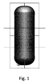
図1は、流体殺菌システム内部で使用するための固定体積の従来技術のチャンバを示す。 FIG. 1 shows a fixed volume prior art chamber for use inside a fluid sterilization system.
図2は、流体で半分満たされた固定体積の従来技術のチャンバを示し、流体の上面の上方に空気体積が見える。 FIG. 2 shows a prior art chamber of fixed volume half filled with fluid, with the air volume visible above the upper surface of the fluid.
図3は、調節可能な壁を取り付けられたチャンバを示し、調節可能な壁は、殺菌されるべき流体の量にチャンバの体積を制限する。調節可能な壁は、好ましくは、UV反射性を有する材料から製造され得る。調節可能な壁の構成に適した材料は、アルミニウムでコーティングされた基体から選択され得るが、アルミニウムから製造され、次いで研磨されることもできる。他の適切な材料は、限定はしないが、銀(Ag)、金(Au)、銅(Cu)、ロジウム(Rh)、及びチタン(Ti)を含み得る。 FIG. 3 shows an adjustable wall mounted chamber, which limits the volume of the chamber to the amount of fluid to be sterilized. The adjustable wall may preferably be made of a material having UV reflectivity. Materials suitable for the adjustable wall configuration may be selected from aluminum coated substrates, but may also be manufactured from aluminum and then polished. Other suitable materials may include, but are not limited to, silver (Ag), gold (Au), copper (Cu), rhodium (Rh), and titanium (Ti).
図4は、図1に示されるチャンバ全体の内部で幾つかの光線によって生成される光線経路の軌跡を示す。光線が、チャンバの体積全体にわたって実質的に一様な分布を有すること、及び光線が、一様な分布でチャンバ壁の表面から反射されることが見て取れる。チャンバ壁に対する光線の入射角と出射角が同様であることが見て取れるため、チャンバ壁は正反射性である。 FIG. 4 shows the ray path trajectory generated by several rays inside the entire chamber shown in FIG. It can be seen that the light beam has a substantially uniform distribution throughout the volume of the chamber, and that the light beam is reflected from the surface of the chamber wall in a uniform distribution. The chamber wall is specular because it can be seen that the incident and outgoing angles of the light beam on the chamber wall are similar.
図5は、図2に示される半分満たされたチャンバ内部で幾つかの光線によって生成される光線経路の軌跡を示す。領域A内部の光線が、領域B内の光線よりも多くの回数の反射を受けることが見て取れる。これは、領域Bが流体であり、領域Aは空気体積であるからである。光線が流体から出るとき、即ち流体の上面を通過するとき、流体とその上の空気との屈折率の差により、流体表面に対する光線の出射角は小さい。この小さい角度は、放射が空気体積内のチャンバの壁によって多数回反射されてチャンバの壁によって吸収される可能性が、流体の上面を通って流体内に戻る可能性よりも高いことを意味する。これは、チャンバの内部で、流体の表面に対して小さい角度で光線が反射されることによって説明され得る。これは、光線が流体の上面に衝突するときに、浅い入射角により、表面から反射されて戻されることを意味する。光線が空気体積内にあるとき、流体の殺菌に非効率的であって寄与せず、従って、流体で完全に満たされたチャンバに比べて、効率の低下をもたらす。 FIG. 5 shows the ray path trajectory generated by several rays within the half-filled chamber shown in FIG. It can be seen that rays within region A receive more reflections than rays within region B. This is because region B is fluid and region A is air volume. When the light beam leaves the fluid, i.e., passes through the upper surface of the fluid, due to the difference in refractive index between the fluid and the air above it, the outgoing angle of the light beam on the fluid surface is small. This small angle means that radiation is more likely to be reflected multiple times by the chamber wall in the air volume and absorbed by the chamber wall than it is likely to get back into the fluid through the top surface of the fluid. . This may be explained by the reflection of light rays at a small angle to the surface of the fluid inside the chamber. This means that when the light beam strikes the top of the fluid it is reflected back from the surface with a shallow angle of incidence. When the light beam is in the air volume, it is inefficient and does not contribute to the sterilization of the fluid, thus resulting in a drop in efficiency as compared to a chamber completely filled with fluid.
図6は、調節可能な壁を備えたチャンバ内の流体内部で幾つかの光線によって生成される軌跡を示す。光が領域B内に閉じ込められていることが見て取れる。領域Bは、調節可能な壁の流体接触面よりも下に提供された流体である。また、流体の上面を通って空気充満領域A内に透過する光はないことも見て取れる。従って、空気充満領域内でチャンバ壁に衝突した後に続いて起こる多数回にわたる光の反射は生じない。これは、チャンバの壁での吸光により失われる光エネルギーの量を制限する。UV光は流体内部に閉じ込められる。これは、光のエネルギーが流体に封じ込められ、従って流体殺菌の効率を高め、それに対応して、流体を殺菌するのに必要とされる時間量を短縮し得ることを意味する。 FIG. 6 shows the trajectories generated by several rays within the fluid in a chamber with adjustable walls. It can be seen that the light is confined in the region B. Region B is the fluid provided below the adjustable wall fluid contact surface. It can also be seen that no light is transmitted through the upper surface of the fluid into the air-filled area A. Thus, the multiple reflections of light that occur subsequent to collision with the chamber wall in the air-filled region do not occur. This limits the amount of light energy lost due to absorption at the chamber walls. UV light is trapped inside the fluid. This means that the energy of light can be contained in the fluid, thus increasing the efficiency of fluid sterilization and correspondingly reducing the amount of time required to sterilize the fluid.
図7は、流体殺菌システムの一実施形態の断面図を示し、ここでは、チャンバ703が、調節可能な壁701を備えている。この調節可能な壁は、チャンバ内部で調節され得、チャンバ内部に可変体積を提供する。チャンバは、底部と、少なくとも1つの側壁とを有する。チャンバの底部は、調節可能な壁に対向する面であり、少なくとも1つの側壁は、底部と調節可能な壁との間に延在する。少なくとも1つの側壁は、好ましくは、調節可能な壁を越えて延在する。前記調節可能な壁は、調節可能な壁の位置とチャンバの底部との間に可変体積チャンバを提供するように構成される。
FIG. 7 shows a cross-sectional view of one embodiment of a fluid sterilization system where the
少なくとも1つのUV光源702が、チャンバ内に含まれる流体709を殺菌するためにチャンバ内にUV放射を放出するために提供される。殺菌が完了した後に流体を取り出すために、流体出口704が備えられる。流体出口は、好ましくは弁を備え、適切なUV放射線量が流体に加えられたことを確認することによって流体の殺菌が完了されるまで、チャンバからの流体流出を防止する。
At least one
図8は、流体殺菌システムの一実施形態の断面図を示し、ここでは、チャンバ803は、調節可能な壁801を備えている。調節可能な壁の位置は、チャンバ内部で調節可能であり、チャンバ内部に可変体積を提供する。その位置は、機械的に又は手動で調節可能であり得る。調節可能な壁は、更に貫通孔805を備える。この貫通孔は、調節可能な壁をチャンバから取り外す必要なくチャンバ803が流体で満たされるようにする。貫通孔は、好ましくは更に弁を備え、そのような弁は一方向弁でよく、前記弁は、流体がチャンバに入るのを可能にするが、UV放射が流体809内部に閉じ込められることを保証し得る。少なくとも1つの光源802が、以下の位置の1つ又は複数に提供される;調節可能な壁に対向する面であるチャンバの底部;又は、底部と調節可能な壁との間に、及び好ましくは調節可能な壁を越えて延在する少なくとも1つの側壁。この位置決めは、チャンバ内に透過されたUV放射が、チャンバ内部の調節可能な壁の位置とはほぼ無関係に、調節可能な壁の流体接触面によって反射されることを保証する。調節可能な壁の流体接触面によるUV放射の反射は、UV放射が中を進むことができる体積を、チャンバ内部の流体の量に制限し、流体殺菌システムの効果を向上させ得る。
FIG. 8 shows a cross-sectional view of one embodiment of a fluid sterilization system where the
図9は、流体殺菌システムの更なる実施形態の断面図を示し、ここでは、チャンバ903が、調節可能な壁901を取り付けられている。この実施形態では、調節可能な壁は、チャンバ内に含まれる流体909の上面で浮動するように構成される。調節可能な壁の位置は、チャンバ内部の流体の液位によって影響を及ぼされる。即ち、チャンバ内に存在する流体の量が大きい程、調節可能な壁は、チャンバの底部から離れた位置にされる。調節可能な壁901は、チャンバ903内部に密着して取り付けられて、流体から逃げ得るUV放射の量及びそれに伴う効率の損失を減少する。調節可能な壁901は、流体量をチャンバに提供するのを容易にするために、チャンバから取外し可能でよい。少なくとも1つの光源902が、以下の位置、調節可能な壁に対向する面であるチャンバの底部、又は、底部と調節可能な壁との間に、及び好ましくは調節可能な壁を越えて延在する少なくとも1つの側壁の1つ又は複数に提供される。この位置決めは、チャンバ内に透過されたUV放射が、チャンバ内部の調節可能な壁の位置とはほぼ無関係に、調節可能な壁の流体接触面によって反射されることを保証する。殺菌が完了した後にチャンバから流体を取り出すために、流体出口904が提供される。
FIG. 9 shows a cross-sectional view of a further embodiment of a fluid sterilization system, wherein a
図10は、流体殺菌システムのなおも更なる実施形態の断面図であり、ここでは、チャンバ1003は、調節可能な壁1001を備え、この調節可能な壁は、チャンバ1003内部にある流体1009の上面で浮動するように構成される。流体は、調節可能な壁1001とチャンバ1003との間の小さい間隙ギャップ1010(見易くするためにこの図では誇張されている)を通過することによってチャンバに入る。このギャップは、チャンバからのUV放射の逃げを最小限に抑えながら、できるだけ短い時間で流体がチャンバに提供され得るように設計されるべきである。これは、殺菌の効果とユーザ安全性との両方に重要である。少なくとも1つの光源1002が、調節可能な壁の流体接触面よりも下に備えられて、UV放射を流体量内に放出する。このUV光源は、調節可能な壁の流体接触面よりも下に位置決めされ得、流体の量、従って調節可能な壁1001の位置とは無関係に、UV放射が流体内に透過されることを保証する。殺菌が完了した後にチャンバ1003からの流体の取出しを容易にするために、流体出口1004が提供される。
FIG. 10 is a cross-sectional view of a still further embodiment of a fluid sterilization system, wherein the
更なる実施形態(図示せず)では、調節可能な壁とチャンバの少なくとも1つの側壁との間の間隙距離が最小限にされ、調節可能な壁の周縁部の周りに開口が提供される。これらの開口は、調節可能な壁の第1の表面から第2の表面に延在する。これらの開口の目的は、チャンバへの流体の提供を可能にすることである。調節可能な壁の周縁部の周りにある一連の開口の利用は、調節可能な壁とチャンバの少なくとも1つの側壁との間の密閉を可能にし、それでも流体がチャンバに供給されるようにすることによって、チャンバ内部での調節可能な壁の位置合わせを保つ。 In a further embodiment (not shown), the gap distance between the adjustable wall and at least one side wall of the chamber is minimized and an opening is provided around the periphery of the adjustable wall. These openings extend from the first surface of the adjustable wall to the second surface. The purpose of these openings is to enable the provision of fluid to the chamber. The use of a series of openings around the periphery of the adjustable wall allows a seal between the adjustable wall and at least one side wall of the chamber so that fluid is still supplied to the chamber Maintain adjustable wall alignment within the chamber.
流体殺菌システム(図示せず)の更なる実施形態では、チャンバは、調節可能な壁を備える。チャンバへの流体入口が提供され、ここで、入口の高さは、調節可能な壁の最大延出位置よりも高い。これは、調節可能な壁を、流体の上面で浮動させ、流体が追加されたときに上昇させる。チャンバ内への流体入口が調節可能な壁の流体接触面よりも下にあることにより、調節可能な壁とチャンバとの間の密閉が可能であり、これは、チャンバからのUV放射の損失を減少し得、それにより殺菌の効果を高め、またUV放射がユーザに危害を及ぼす危険を低下させる。流体の追加前にチャンバ内部に存在する空気は、調節可能な壁によって捕捉され、流体がチャンバに入るのを防止することがあるため、抽気弁が提供され得る。この抽気弁は、チャンバ内部に捕捉された空気の逃げを可能にし、それにより、調節可能な壁の流体接触面よりも下のチャンバの体積が流体で満たされることを保証する。好ましくは、殺菌が完了するまで流体がチャンバから出るのを防止するために、流体出口に弁が取り付けられる。少なくとも1つのUV光源が、調節可能な壁の流体接触面よりも下に備えられ、チャンバ内部での調節可能な壁の位置とは無関係にUV放射を流体内に放出する。 In a further embodiment of the fluid sterilization system (not shown), the chamber comprises an adjustable wall. A fluid inlet to the chamber is provided, wherein the height of the inlet is higher than the maximum extended position of the adjustable wall. This causes the adjustable wall to float on top of the fluid and to rise when fluid is added. By having the fluid inlet into the chamber below the adjustable wall fluid interface, a seal between the adjustable wall and the chamber is possible, which causes the loss of UV radiation from the chamber. It can be reduced, thereby increasing the effectiveness of the sterilization and also reducing the risk of UV radiation harming the user. A bleed valve may be provided as the air present inside the chamber prior to the addition of fluid may be trapped by the adjustable wall and may prevent fluid from entering the chamber. This bleed valve allows the escape of air trapped inside the chamber, thereby ensuring that the volume of the chamber below the adjustable wall fluid contact surface is filled with fluid. Preferably, a valve is attached to the fluid outlet to prevent fluid from exiting the chamber until sterilization is complete. At least one UV light source is provided below the adjustable wall fluid contact surface and emits UV radiation into the fluid regardless of the adjustable wall position inside the chamber.
図11は、流体殺菌システムの更なる実施形態の断面図を示し、ここでは、チャンバ1103が、調節可能な壁1101を取り付けられている。調節可能な壁は、少なくとも1つのUV光源1102を備え、前記光源は、UV放射を放出するように構成される。UV光源は、好ましくは、水晶等の高いUV透過率を有する材料から構成された窓によってカバーされ得る。この窓は、少なくとも1つのUV光源が流体1109に接触するのを防止し、これは、光源の寿命を延ばし得る。殺菌が完了した後にチャンバ1103から流体を取り出すことができるように、流体出口1104が提供される。
FIG. 11 shows a cross-sectional view of a further embodiment of a fluid sterilization system, wherein a
図12は、流体殺菌システムの一実施形態の断面図を示し、ここでは、チャンバ1203は、調節可能な壁1201を備えている。調節可能な壁は、高いUV透過率を有する材料の少なくとも一部分1208を備えている。その材料部分1208は、流体1209が少なくとも1つのUV光源に接触しないようにする。そのような接触は、UV光源1202に悪影響があることが分かり得る。材料部分1208は、UV光源によって放出されるUV光を、チャンバ1203内部に含まれる流体内に透過させる。この構成は、調節可能な壁1201の位置とは無関係に、UV光源からの光がチャンバ1203内に含まれる流体内に常に透過されることを保証するため、有利であると分かり得る。調節可能な壁1201は、流体の上面で浮動することができ、従って、チャンバ内部の調節可能な壁の位置は、チャンバに提供される流体の量によって影響を及ぼされる。殺菌が完了した後にチャンバ1203から流体を取り出すことができるように、流体出口1204が提供される。好ましくは、流体出口は、弁を取り付けられて、殺菌が完了される前の流体の流出を防止する。
FIG. 12 shows a cross-sectional view of one embodiment of a fluid sterilization system, wherein the
Claims (11)
− 前記チャンバにUV放射を提供するための少なくとも1つのUV光源と、
− 少なくとも1つの調節可能なチャンバ壁と
を有する流体殺菌システムであって、
− 前記調節可能な壁が、前記チャンバ内部の前記流体の表面上で浮動し、且つ流体液位が増加又は減少されるときに流体接触したままであり、それにより、前記UV放射を前記流体内に閉じ込めるように前記チャンバの前記体積を前記流体の量に合わせて調節し、前記チャンバが更に、UV反射性材料の少なくとも一部分を有する、流体殺菌システム。 A chamber having a volume for receiving a fluid;
At least one UV light source for providing UV radiation to the chamber;
A fluid sterilization system having at least one adjustable chamber wall,
-The adjustable wall floats on the surface of the fluid inside the chamber and remains in fluid contact when the fluid level is increased or decreased, whereby the UV radiation is in the fluid Adjusting the volume of the chamber to the volume of the fluid so as to confine it, wherein the chamber further comprises at least a portion of a UV reflective material.
− チャンバに流体を提供するステップであって、前記チャンバが、前記流体を受け取るための体積を有し、前記チャンバが、少なくとも1つの調節可能な壁を更に備え、前記少なくとも1つの調節可能な壁が前記チャンバ内部の前記流体の表面上で浮動する、前記少なくとも1つの調節可能な壁の位置が前記チャンバに対して調節可能である、ステップと、
− 前記チャンバ内に含まれる前記流体にUV放射を提供するステップと
を含む、方法。 A method for sterilizing a fluid,
Providing a fluid to a chamber, the chamber having a volume for receiving the fluid, the chamber further comprising at least one adjustable wall, the at least one adjustable wall Wherein the position of the at least one adjustable wall is adjustable relative to the chamber, wherein the at least one adjustable wall floats on a surface of the fluid inside the chamber.
Providing UV radiation to the fluid contained in the chamber.
− 前記流体に提供されるべき所要のUV放射線量を計算するステップと、
− 前記所要のUV放射線量を前記流体に提供するステップと
を更に含む、請求項10に記載の流体量を殺菌するための方法。 Measuring the amount of fluid inside the chamber;
Calculating the required UV radiation dose to be provided to the fluid;
-Providing the required UV radiation dose to the fluid, the method for sterilizing fluid volumes according to claim 10.
Applications Claiming Priority (3)
| Application Number | Priority Date | Filing Date | Title |
|---|---|---|---|
| EP14154714 | 2014-02-11 | ||
| EP14154714.1 | 2014-02-11 | ||
| PCT/EP2015/051748 WO2015121071A1 (en) | 2014-02-11 | 2015-01-29 | Recipient with variable geometry for uv water purification |
Publications (3)
| Publication Number | Publication Date |
|---|---|
| JP2017505227A JP2017505227A (en) | 2017-02-16 |
| JP2017505227A5 JP2017505227A5 (en) | 2018-03-08 |
| JP6541671B2 true JP6541671B2 (en) | 2019-07-10 |
Family
ID=50072979
Family Applications (1)
| Application Number | Title | Priority Date | Filing Date |
|---|---|---|---|
| JP2016550708A Expired - Fee Related JP6541671B2 (en) | 2014-02-11 | 2015-01-29 | Receiver with variable geometry for clean water by UV |
Country Status (6)
| Country | Link |
|---|---|
| US (1) | US10221080B2 (en) |
| EP (1) | EP3105187B1 (en) |
| JP (1) | JP6541671B2 (en) |
| CN (1) | CN105980312B (en) |
| RU (1) | RU2676618C2 (en) |
| WO (1) | WO2015121071A1 (en) |
Families Citing this family (5)
| Publication number | Priority date | Publication date | Assignee | Title |
|---|---|---|---|---|
| JP7121054B2 (en) * | 2017-05-26 | 2022-08-17 | アキューバ、テクノロジーズ、インコーポレーテッド | Fluid sterilization apparatus and method |
| WO2021149041A1 (en) | 2020-01-22 | 2021-07-29 | Strauss Water Ltd | Liquid disinfecting module |
| WO2021236413A1 (en) | 2020-05-18 | 2021-11-25 | Wangs Alliance Corporation | Germicidal lighting |
| US11027038B1 (en) | 2020-05-22 | 2021-06-08 | Delta T, Llc | Fan for improving air quality |
| DE102021202957A1 (en) * | 2021-03-25 | 2022-09-29 | Osram Gmbh | DEVICE AND METHOD FOR IRADIATION OF A LIQUID |
Family Cites Families (14)
| Publication number | Priority date | Publication date | Assignee | Title |
|---|---|---|---|---|
| US3589862A (en) * | 1968-05-15 | 1971-06-29 | Louis P Veloz | Storage apparatus for water purification system |
| JPS5754443U (en) * | 1980-09-17 | 1982-03-30 | ||
| JPS5754443A (en) | 1980-09-18 | 1982-03-31 | Nec Corp | Optical pulse transmitting and receiving system |
| US6312608B1 (en) * | 1998-08-06 | 2001-11-06 | Lynn Buckner | Sterilizing conduit for beverage storage and dispensing |
| RU2233243C1 (en) * | 1999-10-21 | 2004-07-27 | Лайтстрим Текнолоджиз, Инк. | Method and device for disinfecting liquids with ultraviolet radiation |
| CN2727150Y (en) * | 2004-06-24 | 2005-09-21 | 上海万森水处理有限公司 | Immersion type UV sterilizer for water body |
| US7520978B2 (en) | 2005-06-17 | 2009-04-21 | Philips Lumileds Lighting Co., Llc | Fluid purification system with ultra violet light emitters |
| JP2009506860A (en) * | 2005-09-06 | 2009-02-19 | アトランティウム テクノロジーズ エルティディ. | Sterilization method, apparatus and system by light irradiation |
| AU2007284040B2 (en) * | 2006-08-17 | 2013-01-17 | Trojan Technologies | Fluid treatment system |
| EP2394963B1 (en) | 2008-11-21 | 2016-02-17 | The University of Tokushima | Ultraviolet sterilization device for outdoor water |
| JP2012143731A (en) * | 2011-01-14 | 2012-08-02 | Harison Toshiba Lighting Corp | Ultraviolet ray irradiation apparatus |
| JP5848530B2 (en) * | 2011-06-23 | 2016-01-27 | 株式会社日本フォトサイエンス | Sterilizer for containers with caps |
| JP2013066835A (en) * | 2011-09-22 | 2013-04-18 | Harison Toshiba Lighting Corp | Ultraviolet ray irradiation apparatus |
| US10442704B2 (en) * | 2013-01-18 | 2019-10-15 | Sensor Electronic Technology, Inc. | Ultraviolet fluid disinfection system with feedback sensor |
-
2015
- 2015-01-29 EP EP15702441.5A patent/EP3105187B1/en active Active
- 2015-01-29 WO PCT/EP2015/051748 patent/WO2015121071A1/en active Application Filing
- 2015-01-29 RU RU2016134840A patent/RU2676618C2/en active
- 2015-01-29 US US15/116,611 patent/US10221080B2/en active Active
- 2015-01-29 JP JP2016550708A patent/JP6541671B2/en not_active Expired - Fee Related
- 2015-01-29 CN CN201580008073.8A patent/CN105980312B/en active Active
Also Published As
| Publication number | Publication date |
|---|---|
| CN105980312B (en) | 2019-05-31 |
| US20160355410A1 (en) | 2016-12-08 |
| WO2015121071A1 (en) | 2015-08-20 |
| US10221080B2 (en) | 2019-03-05 |
| RU2016134840A3 (en) | 2018-07-25 |
| EP3105187A1 (en) | 2016-12-21 |
| EP3105187B1 (en) | 2017-06-21 |
| RU2016134840A (en) | 2018-03-15 |
| RU2676618C2 (en) | 2019-01-09 |
| JP2017505227A (en) | 2017-02-16 |
| CN105980312A (en) | 2016-09-28 |
Similar Documents
| Publication | Publication Date | Title |
|---|---|---|
| JP6541671B2 (en) | Receiver with variable geometry for clean water by UV | |
| JP5199093B2 (en) | UV light processing chamber | |
| JP5374697B2 (en) | UV sterilization water purifier and UV LED unit used for it | |
| JP6374403B2 (en) | Method and apparatus for liquid disinfection with light emitted from light emitting diodes | |
| KR20150080489A (en) | Ultraviolet sterilizer and sterilization method | |
| US20170057842A1 (en) | Fluid Disinfection Using Ultraviolet Light | |
| US20070272877A1 (en) | In-Line Treatment of Liquids and Gases by Light Irradiation | |
| KR20120017021A (en) | Ultraviolet light treatment chamber | |
| JP2016531746A (en) | Apparatus and method for liquid treatment with uniform dispersion of ultraviolet light | |
| JP2014233712A (en) | Ultraviolet sterilization device | |
| US20030086817A1 (en) | Blood purification system | |
| WO2013153728A1 (en) | Ultraviolet ray sterilization device | |
| JP2011212573A (en) | Method and apparatus for sterilizing liquid | |
| JP5924394B2 (en) | Liquid sterilization method | |
| JP6606703B2 (en) | Beverage sterilization unit and water server equipped with this beverage sterilization unit | |
| CN213012393U (en) | Drinking water disinfection device with rear ultraviolet lamp | |
| KR101583562B1 (en) | Water treating apparatus | |
| JP2024008165A (en) | Sterilizer | |
| JP2022062415A (en) | Fluid sterilization apparatus, fluid sterilization method, water treatment facility, and water purification equipment | |
| KR20220106333A (en) | Sterilizer using UV-C LED | |
| JP2020032158A (en) | Ultraviolet light sterilization apparatus | |
| CS269301B1 (en) | Ultra violet radiator intended for water disinfection |
Legal Events
| Date | Code | Title | Description |
|---|---|---|---|
| A521 | Request for written amendment filed |
Free format text: JAPANESE INTERMEDIATE CODE: A523 Effective date: 20180126 |
|
| A621 | Written request for application examination |
Free format text: JAPANESE INTERMEDIATE CODE: A621 Effective date: 20180126 |
|
| RD02 | Notification of acceptance of power of attorney |
Free format text: JAPANESE INTERMEDIATE CODE: A7422 Effective date: 20180530 |
|
| A977 | Report on retrieval |
Free format text: JAPANESE INTERMEDIATE CODE: A971007 Effective date: 20180619 |
|
| RD04 | Notification of resignation of power of attorney |
Free format text: JAPANESE INTERMEDIATE CODE: A7424 Effective date: 20180619 |
|
| A131 | Notification of reasons for refusal |
Free format text: JAPANESE INTERMEDIATE CODE: A131 Effective date: 20180628 |
|
| A521 | Request for written amendment filed |
Free format text: JAPANESE INTERMEDIATE CODE: A523 Effective date: 20180927 |
|
| A131 | Notification of reasons for refusal |
Free format text: JAPANESE INTERMEDIATE CODE: A131 Effective date: 20190213 |
|
| A521 | Request for written amendment filed |
Free format text: JAPANESE INTERMEDIATE CODE: A523 Effective date: 20190509 |
|
| TRDD | Decision of grant or rejection written | ||
| A01 | Written decision to grant a patent or to grant a registration (utility model) |
Free format text: JAPANESE INTERMEDIATE CODE: A01 Effective date: 20190522 |
|
| A61 | First payment of annual fees (during grant procedure) |
Free format text: JAPANESE INTERMEDIATE CODE: A61 Effective date: 20190611 |
|
| R150 | Certificate of patent or registration of utility model |
Ref document number: 6541671 Country of ref document: JP Free format text: JAPANESE INTERMEDIATE CODE: R150 |
|
| LAPS | Cancellation because of no payment of annual fees |