JP6541594B2 - Roller lifter structure - Google Patents
Roller lifter structure Download PDFInfo
- Publication number
- JP6541594B2 JP6541594B2 JP2016050990A JP2016050990A JP6541594B2 JP 6541594 B2 JP6541594 B2 JP 6541594B2 JP 2016050990 A JP2016050990 A JP 2016050990A JP 2016050990 A JP2016050990 A JP 2016050990A JP 6541594 B2 JP6541594 B2 JP 6541594B2
- Authority
- JP
- Japan
- Prior art keywords
- lifter
- main body
- guide hole
- roller
- detent
- Prior art date
- Legal status (The legal status is an assumption and is not a legal conclusion. Google has not performed a legal analysis and makes no representation as to the accuracy of the status listed.)
- Expired - Fee Related
Links
- 230000002093 peripheral effect Effects 0.000 claims description 75
- 239000000446 fuel Substances 0.000 description 8
- 238000005192 partition Methods 0.000 description 5
- 230000015572 biosynthetic process Effects 0.000 description 2
- 238000002485 combustion reaction Methods 0.000 description 2
- 238000000034 method Methods 0.000 description 2
- 230000006835 compression Effects 0.000 description 1
- 238000007906 compression Methods 0.000 description 1
- 239000012141 concentrate Substances 0.000 description 1
Images


Landscapes
- Fuel-Injection Apparatus (AREA)
- Valve-Gear Or Valve Arrangements (AREA)
Description
本発明は、ローラリフタ構造に関する。 The present invention relates to a roller lifter structure.
この種のローラリフタ構造として、自動車の内燃機関の燃料供給ポンプに用いられるポンプリフタを備えたものが知られている。例えば、特許文献1に開示されたポンプリフタは、カムの外周面に接触するローラと、ローラを回転可能に支持する軸支ピンと、軸支ピンの軸方向両端部を保持する一対の支持部を有するとともにシリンダ(リフタガイド)の内壁に摺動可能な摺動面を有する円筒状のリフタ本体とを備えている。 As a roller lifter structure of this type, one having a pump lifter used for a fuel supply pump of an internal combustion engine of a car is known. For example, the pump lifter disclosed in Patent Document 1 has a roller that contacts the outer peripheral surface of the cam, a pivot pin that rotatably supports the roller, and a pair of support portions that hold both axial ends of the pivot pin. And a cylindrical lifter body having a sliding surface capable of sliding on the inner wall of the cylinder (lifter guide).
ところで、リフタ本体は、カムのカムプロフィールにしたがって往復移動する一方でその移動方向と交差する方向の分力を受けるため、リフタガイドの内壁との隙間範囲で多少なりとも傾いてしまう。この場合に、リフタの摺動面はほぼ真円の外周形状を呈するため、例えば、リフタガイドの内壁が上下方向に沿って配置されていると、リフタの摺動面のうち、軸支ピンの軸方向と直交する方向で対向する部分が、上端と下端において、内壁に点接触状態で当接することになる。その結果、リフタガイドとリフタとの当接部分の接触圧が過大になり、リフタガイドまたはリフタが摩耗するおそれがある。とくに、リフタ本体は、その移動中に回り止め部によって回転規制された状態に保たれるため、当接部分の範囲が周方向に変化せず、摩耗の問題がより顕著になるという事情がある。 By the way, the lifter body reciprocates according to the cam profile of the cam while receiving a component force in the direction intersecting with the moving direction, so it is inclined to some extent in the clearance range with the inner wall of the lifter guide. In this case, since the sliding surface of the lifter has an almost perfect circular outer peripheral shape, for example, when the inner wall of the lifter guide is arranged along the vertical direction, the sliding pin of the supporting pin of the sliding surface of the lifter The portions opposed in the direction orthogonal to the axial direction contact the inner wall at the upper end and the lower end in a point contact state. As a result, the contact pressure at the contact portion between the lifter guide and the lifter becomes excessive, which may cause the lifter guide or the lifter to wear. In particular, since the lifter main body is kept in a state of being rotationally restricted by the detent during the movement, the range of the contact portion does not change in the circumferential direction, and the problem of wear becomes more significant. .
本発明は上記のような事情に基づいて完成されたものであって、リフタガイドまたはリフタが摩耗するのを抑制することが可能なローラリフタ構造を提供することを目的とする。 The present invention is completed based on the above-mentioned circumstances, and it aims at providing a roller lifter structure which can control that a lifter guide or a lifter wears out.
本発明のローラリフタの構造は、カムの外周面に接触するローラと、前記ローラを回転可能に支持する軸部材と、前記軸部材の軸方向両端部を保持し、リフタガイドに設けられた断面円形のガイド孔に往復移動可能に収容される円筒状のリフタ本体と、を備え、前記リフタ本体の外周面のうち、前記軸部材の軸方向と直交する方向で対向する部分に、前記ガイド孔の内周面から逃げる形態の非接触部を有し、前記非接触部の周方向両側で前記ガイド孔の内周面と接触する接触部を有しているところに特徴を有する。 The structure of the roller lifter according to the present invention comprises a roller in contact with the outer peripheral surface of a cam, a shaft member rotatably supporting the roller, and both end portions in the axial direction of the shaft member. And a cylindrical lifter body housed reciprocally movably in the guide hole of the guide hole, in a portion of the outer peripheral surface of the lifter body facing in a direction orthogonal to the axial direction of the shaft member, the guide hole It has a feature in that it has a noncontacting part of a form which escapes from an inner skin, and has a contact part in contact with the inner skin of the above-mentioned guide hole on both sides in the circumferential direction of the noncontact.
カムが回転すると、軸部材に支持されたローラが従動回転し、リフタ本体の外周面のうち、軸部材の軸方向と直交する方向で対向する部分が、移動方向の端部で、ガイド孔の内周面に点接触して大きな接触圧を発生させ、リフタガイドまたはリフタが摩耗するおそれがある。しかるに本発明によれば、リフタ本体の外周面のうち、軸部材の軸方向と直交する方向で対向する部分に、非接触部を有し、接触部が非接触部の周方向両側でガイド孔の内周面と接触する構成になっているため、ガイド孔の内周面に点接触する場合に比べて応力が分散され、リフタガイドまたはリフタが摩耗するのを抑制することができる。 When the cam rotates, the roller supported by the shaft member is driven to rotate, and a portion of the outer peripheral surface of the lifter body facing in the direction orthogonal to the axial direction of the shaft member is an end portion in the moving direction of the guide hole. Point contact with the inner circumferential surface generates a large contact pressure, which may cause the lifter guide or the lifter to wear. However, according to the present invention, the outer peripheral surface of the lifter body has a non-contacting portion at a portion facing in a direction orthogonal to the axial direction of the shaft member, and the contact portion is a guide hole at both circumferential directions of the non-contacting portion. Since the structure is in contact with the inner circumferential surface of the guide hole, the stress is dispersed as compared with the case of point contact with the inner circumferential surface of the guide hole, and it is possible to suppress the lifter guide or the lifter from being worn.
本発明の好ましい形態を以下に示す。
前記リフタ本体は、前記ガイド孔の内周面に沿って設けられた回り止め溝に進入する形態の回り止め部を有し、前記非接触部は、前記リフタ本体の外周面において、前記回り止め部の径方向反対側に設けられ、前記回り止め部側には設けられていない。回り止め部が回り止め溝に進入することにより、リフタ本体の外周面のうち回り止め部を挟んだ周方向両側の部分が、ガイド溝の内周面のうち回り止め溝を挟んだ周方向両側の部分に接触することになる。したがって、リフタ本体の回り止め部が位置する側では点接触状態にならないため、摩耗抑制手段として、非接触部を設ける必要がない。その結果、リフタ本体の構成を簡素化することができる。
Preferred embodiments of the present invention are shown below.
The lifter body has a detent portion configured to enter a detent groove provided along the inner circumferential surface of the guide hole, and the noncontact portion is the detent on the outer circumferential surface of the lifter body. It is provided on the diametrically opposite side of the part, and is not provided on the side of the detent part. When the detent portion enters the detent groove, portions on both sides in the circumferential direction of the lifter main body on both sides of the detent portion in the circumferential direction sandwich the detent groove on the inner peripheral surface of the guide groove. Will be in contact with the Therefore, since the point contact state does not occur on the side where the detent portion of the lifter main body is located, it is not necessary to provide a non-contact portion as the wear suppressing means. As a result, the structure of the lifter body can be simplified.
前記リフタ本体の内周面のうち、前記リフタ本体の厚み方向反対側で前記非接触部と対向する部分に、円周方向に沿った円周面を有している。これによれば、非接触部の存在によってリフタ本体の内部スペースが制約を受けることがなく、内部スペースを有効に活用することができる。 A circumferential surface is provided along a circumferential direction at a portion of the inner peripheral surface of the lifter main body opposite to the non-contact portion on the side opposite to the thickness direction of the lifter main body. According to this, the inner space of the lifter main body is not restricted by the presence of the non-contact portion, and the inner space can be effectively used.
<実施例1>
本発明の実施例1を図1〜図4によって説明する。実施例1のローラリフタ構造は、図4に示す自動車の内燃機関の燃料供給装置90に適用されるポンプリフタの構造を例示するものである。
Example 1
A first embodiment of the present invention will be described with reference to FIGS. The roller lifter structure of the first embodiment exemplifies the structure of a pump lifter applied to a
燃料供給装置90は、ローラリフタ10で高圧に調整された燃料を図示しないエンジンの燃料室に供給するものである。ローラリフタ10は、シリンダヘッドのリフタガイド91に組み込まれている。
The
図4に示すように、リフタガイド91は、ハウジング92と、ハウジング92の上端部に嵌合される蓋材93とを有している。蓋材93には、上下方向に貫通する断面円形の貫通孔94が設けられている。蓋材93の貫通孔94には、プランジャ60が上下方向に往復移動可能に挿入される。プランジャ60の上端部は、貫通孔94の上端に連通する図示しない圧力室に進退可能とされている。プランジャ60の上端部が圧力室に進入することで、圧力室の燃料が加圧される。
As shown in FIG. 4, the
ハウジング92には、ガイド孔95が設けられている。ガイド孔95は、断面円形、詳細には断面真円形をなし、上下方向に延出してハウジング92の下端に開口している。ガイド孔95は、上端がハウジング92に嵌合される蓋材93によって閉塞され、貫通孔94と同軸で連通する形態になっている。ハウジング92のガイド孔95には、ローラリフタ10のリフタ本体11が上下方向に往復移動可能に挿入される。
The
また、ハウジング92には、ガイド孔95と連通する回り止め溝96が設けられている。回り止め溝96は、ガイド孔95の内周面に沿って上下方向に延出し、ハウジング92の下端に開口している。ガイド孔95の上端は、蓋材93で閉塞されている。ガイド孔95の上下方向の長さは、ローラリフタ10の移動ストローク(リフタ量)に応じて設定される。
Further, the
リフタ本体11は、上下方向にほぼ沿った円筒状の周壁12を有している。周壁12は、その外周面がガイド孔95の内周面に沿って配置され、ガイド孔95に往復移動可能かつ摺動可能に収容される。
The lifter
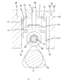
リフタ本体11は、周壁12の内部を上下に分割する隔壁13を有している。隔壁13は、径方向に沿った平板状をなし、周壁12の内周面の上下方向途中に一体に連なる形態になっている。なお、周壁12の内周面のうち、隔壁13の上方の部分は、円周方向に沿った断面円形の円周面14になっている。
The lifter
リフタ本体11の内部のうち、隔壁13の上方の空間には、プランジャ60の下側部分と、リテーナ61と、付勢部材62とが、収容されている。リテーナ61は、径方向に沿った円盤状をなし、その中心部の膨出部分にプランジャ60の下端部が係止して固定されている。付勢部材62は、圧縮コイルばねからなるばね材であって、その下端がリテーナ61の上面の外周縁部に当接し、その上端がリフタガイド91の蓋材93の下面に当接し、全体として上下方向に弾性的に伸縮可能とされている。付勢部材62は、リフタ本体11をカム70側に付勢している。
The lower portion of the
図2に示すように、周壁12の下端部の左右両端部には、下方へ行くにしたがって次第に近づく方向に傾斜する一対の傾斜部15が設けられている。また、リフタ本体11は、両傾斜部15の下端から下方へ突出する一対の支持壁16を有している。両支持壁16は、平板状をなし、互いに平行に配置されている。
As shown in FIG. 2, at the left and right end portions of the lower end portion of the
リフタ本体11の内部のうち、隔壁13の下方の空間で、かつ両支持壁16間の位置には、ローラ80が収容されている。ローラ80は、軸部材81に支持され、軸部材81に対してニードル軸受などの軸受82(図4を参照)を介して回転可能とされている。軸部材81は、軸方向(図1〜図3のX方向)に細長い円柱ピン状をなし、軸方向両端部が両支持壁16に保持されている。
A
ローラ80は、下端部が支持壁16の下方に突出して配置され、下端外周面がカム70の外周面に摺動可能に接触し、付勢部材62の付勢力を受けてカム70の外周面に押し付けられる。カム70は、側面視で略三角形状の外形状をなし、カムシャフト71に設けられている。カムシャフト71と軸部材81は、互いに平行な軸心を有している。
The lower end portion of the
また、図3に示すように、リフタ本体11は、周壁12の下端後縁(図3の紙面手前側を後側とする)からいったん下方へ突出したあと後方へ小さく突出するように屈曲した板片状の回り止め部17を有している。図4に示すように、回り止め部17は、周壁12がガイド孔95に収容されたときに回り止め溝96に進入し、周壁12が上下方向に移動するのに伴い、上下方向に変位可能とされている。
Further, as shown in FIG. 3, the lifter
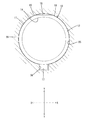
図1に示すように、周壁12の外周面には、断面円形の円周部分から内側に引っ込む形態の非接触部18が設けられている。周壁12がガイド孔95に収容された状態では、非接触部18が、ガイド孔95の内周面から退避するように逃げ、ガイド孔95の内周面と非接触状態に保たれる。
As shown in FIG. 1, a
ここで、非接触部18は、周壁12の外周面のうち、軸部材81の軸方向(図1のX方向)と直交する方向(図1のY方向)に対向する部分で、かつ回り止め部17の位置する側とは径方向反対側の位置に、上下方向に直線状に延出して設けられている。より具体的には、非接触部18は、平面視方向から見て周壁12の外周の弦方向に沿った直線状の平坦面を有し(図1を参照)、周壁12の上下方向の全長にわたって延出し、周壁12の上下両端に開口している(図2を参照)。また、非接触部18は、周壁12の周方向の一カ所にのみ設けられている。周壁12の内周面のうち、周壁12の厚み方向に関して非接触部18と反対側の部分は、円弧状をなし、円周面14の一部を構成している。このため、周壁12は、非接触部18を有する部分が隣接する部分よりも薄肉になっている。
Here, the
図1に示すように、周壁12の外周面には、非接触部18の周方向両側に、断面円形の円周部分に沿った接触部19を有している。周壁12がガイド孔95に収容された状態では、接触部19が、ガイド孔95の内周面に沿って接触可能に配置される。接触部19は、周壁12の外周面のうち、非接触部18及び傾斜部15と対応する領域を除いた部分に、円弧状、詳細には優弧状に設けられている。
As shown in FIG. 1, on the outer peripheral surface of the
次に、本実施例1のローラリフタ10の動作について説明する。
カム70がカムシャフト71の軸周りに回転すると、ローラ80が従動回転する。燃料の吸入工程では、リフタ本体11が付勢部材62の付勢力により押圧され、周壁12の接触部19がガイド孔95の内周面を摺動しつつ下方に変位するとともに、プランジャ60が同様に下方に変位して、プランジャ60の上端部が圧力室から退避する。一方、燃料の吐出工程では、リフタ本体11が付勢部材62の付勢力に抗して、周壁12の接触部19がガイド孔95の内周面を摺動しつつ上方に変位するとともに、プランジャ60が同様に上方に変位して、プランジャ60の上端部が圧力室に進入する。こうしてリフタ本体11がガイド孔95を上下方向に往復移動する間、回り止め部17の先端部が回り止め溝96に進入して逃がされる。
Next, the operation of the
When the
また、カム70が回転すると、カム70のカムプロフィールにしたがって、リフタ本体11の周壁12が、ガイド孔95を上下方向に往復移動するとともに、軸部材81の軸方向(カムシャフト71の軸方向と同じ)と直交する方向(図1のY方向)への分力を受け、ガイド孔95の内周面との隙間範囲で、わずかな傾き(コッキング)が生じることになる。
Further, when the
本実施例1の場合、リフタ本体11の外周面のうち、軸部材81の軸方向と直交する方向で対向する部分に、非接触部18を有し、非接触部18がガイド孔95の内周面から離れて配置され、非接触部18の周方向両側に位置する接触部19がガイド孔95の内周面に接触して配置される。例えば、リフタ本体11の上端が非接触部18の位置する側に倒れ込むように傾くと、リフタ本体11の上端の非接触部18がガイド孔95の内周面とは接触せずに、リフタ本体11の上端の接触部19がガイド孔95の内周面と接触することになる。このため、リフタ本体11の上端がガイド孔95の内周面に点接触状態で当接することがなく、リフタ本体11の上端の一箇所に応力が集中する事態を回避することができる。
In the case of the first embodiment, of the outer peripheral surface of the lifter
また、リフタ本体11の外周面のうち、軸部材81の軸方向と直交する方向で対向する部分で、かつ非接触部18の径方向反対側の部分に、回り止め部17を有しているため、リフタ本体11の上端が非接触部18の位置する側に倒れ込むように傾くと、リフタ本体11の下端の回り止め部17が回り止め溝96に進入して逃がされ、リフタ本体11の外周面のうち、回り止め部17を挟んだ周方向両側の部分が、ガイド孔95の内周面のうち、回り止め溝96を挟んだ周方向両側の部分に接触することになる。このため、上記同様、リフタ本体11の下端がガイド孔95の内周面に点接触状態で当接することがなく、リフタ本体11の下端の一箇所に応力が集中する事態を回避することができる。
Further, in the portion of the outer peripheral surface of the lifter
一方、リフタ本体11の上端が回り止め部17の位置する側に倒れ込むように傾く場合には、上記とは逆に、リフタ本体11の下端の非接触部18がガイド孔95の内周面と接触しないことで、リフタ本体11の下端に加わる応力が分散されるとともに、回り止め部17が回り止め溝96に進入して逃がされて、リフタ本体11の上端に加わる応力が分散される。
On the other hand, when the upper end of the lifter
その結果、リフタガイド91またはリフタ本体11が摩耗するのを抑制することができ、耐久性の向上、及びリフタ本体11の移動動作の信頼性の向上を図ることができる。
As a result, wear of the
また、本実施例1の場合、リフタ本体11の外周面のうち、回り止め部17が位置する側には、非接触部18が設けられていないため、その分、リフタ本体11の構成を簡素化することができる。
さらに、リフタ本体11の内周面のうち、リフタ本体11の厚み方向反対側で非接触部18と対向する部分に、円周方向に沿った円周面14を有しており、周壁12の内周面の真円形状が維持されているため、非接触部18の存在によってリフタ本体11の内部スペースが制約を受けることがなく、内部スペースに、リテーナ61、付勢部材62及びプランジャ60を支障なく収容することができる。
Further, in the case of the first embodiment, since the
Furthermore, a
<実施例2>
図5は、本発明の実施例2を示す。実施例2は、非接触部18Aの形状が実施例1と異なるが、その他は実施例1と同様である。このため、実施例1と同様の構造には同一符号を付し、実施例1と重複する説明を省略する。
Example 2
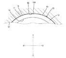
FIG. 5 shows Example 2 of the present invention. The second embodiment is the same as the first embodiment, except that the shape of the
この非接触部18Aは、平面視方向から見て径方向外側に膨出する円弧状の断面形状をなし、接触部19の曲率半径より大きい曲率半径を有している。このため、非接触部18Aは、接触部19に段差なく曲面状に連続する形態になっている。周壁12がガイド孔95に収容されると、非接触部18Aは、実施例1の直線状の非接触部18Aに比べてガイド孔95の内周面の近くに配置されるものの、ガイド孔95の内周面と非接触状態に保たれる。なお、非接触部18Aの形成位置(周壁12の外周面のうち、軸部材81の軸方向(図5のX方向)と直交する方向(図5のY方向)に対向する部分で、かつ回り止め部17の位置する側とは径方向反対側の位置)は実施例1と同様である。
The
実施例2によれば、リフタ本体11の周壁12の強度を良好に確保することができるとともに、従前のリフタ本体11と外観上類似しているため、意匠性を低下させることもない。
According to the second embodiment, the strength of the
<実施例3>
図6は、本発明の実施例3を示す。実施例3も、非接触部18Bの形状が実施例1と異なり、その他は実施例1と同様である。
Example 3
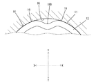
FIG. 6 shows Example 3 of the present invention. The third embodiment is also the same as the first embodiment except for the shape of the
この非接触部18Bは、平面視方向から見て径方向内側に膨出する円弧状の断面形状をなし、周方向両側の接触部19から略U字に凹む形態になっている。リフタ本体11の周壁12の内周面のうち、周壁12の厚み方向に関して非接触部18Bと反対側の部分は、非接触部18Bと同様に、径方向内側に膨出する形態になっている。周壁12は、接触部19から非接触部18Bにかけて全周にわたって同一の厚みで構成されている。非接触部18Bの形成位置(周壁12の外周面のうち、軸部材81の軸方向(図6のX方向)と直交する方向(図6のY方向)に対向する部分で、かつ回り止め部17の位置する側とは径方向反対側の位置)は実施例1と同様である。
The
実施例3によれば、ローラリフタ10が小型になっても、非接触部18Bを容易に形成することができる。
According to the third embodiment, even if the
<他の実施例>
以下、他の実施例を簡単に説明する。
(1)非接触部は、リフタ本体の周壁の外周面のうち、軸部材の軸方向と直交する方向で対向する部分の、上端部と下端部にのみ、設けられる構成であってもよい。
(2)リフタ本体の外周面のうち、回り止め部の位置する側に、非接触部を設けても構わない。
(3)本発明は、レシプロエンジンの動弁機構において、吸排気口を開閉するバルブにカムの回転力を伝達するバルブリフタに適用可能である。
Other Embodiments
Other embodiments will be briefly described below.
(1) The non-contacting portion may be provided only on the upper end portion and the lower end portion of the portion of the outer peripheral surface of the peripheral wall of the lifter main body facing in the direction orthogonal to the axial direction of the shaft member.
(2) A non-contacting portion may be provided on the side of the outer circumferential surface of the lifter main body where the rotation preventing portion is located.
(3) The present invention is applicable to a valve lifter that transmits the rotational force of a cam to a valve that opens and closes an intake and exhaust port in a valve operating mechanism of a reciprocating engine.
10…ローラリフタ
11…リフタ本体
14…円周面
17…回り止め部
18…非接触部
19…接触部
70…カム
80…ローラ
81…軸部材
91…リフタガイド
95…ガイド孔
96…回り止め溝
DESCRIPTION OF
Claims (3)
前記ローラを回転可能に支持する軸部材と、
前記軸部材の軸方向両端部を保持し、リフタガイドに設けられた断面円形のガイド孔に往復移動可能に収容される円筒状のリフタ本体と、を備え、
前記リフタ本体の外周面のうち、前記軸部材の軸方向と直交する方向で対向する部分に、前記ガイド孔の内周面から逃げる形態の非接触部を有し、前記非接触部の周方向両側で前記ガイド孔の内周面と接触する接触部を有していることを特徴とするローラリフタ構造。 A roller contacting the outer circumferential surface of the cam;
A shaft member rotatably supporting the roller;
And a cylindrical lifter main body which holds both axial ends of the shaft member and is accommodated so as to be reciprocally movable in a guide hole having a circular cross section provided in the lifter guide,
A non-contacting portion having a form of escaping from the inner peripheral surface of the guide hole is provided on a portion of the outer peripheral surface of the lifter main body facing in a direction orthogonal to the axial direction of the shaft member. A roller lifter structure comprising a contact portion that contacts the inner circumferential surface of the guide hole on both sides.
Priority Applications (1)
| Application Number | Priority Date | Filing Date | Title |
|---|---|---|---|
| JP2016050990A JP6541594B2 (en) | 2016-03-15 | 2016-03-15 | Roller lifter structure |
Applications Claiming Priority (1)
| Application Number | Priority Date | Filing Date | Title |
|---|---|---|---|
| JP2016050990A JP6541594B2 (en) | 2016-03-15 | 2016-03-15 | Roller lifter structure |
Publications (2)
| Publication Number | Publication Date |
|---|---|
| JP2017166368A JP2017166368A (en) | 2017-09-21 |
| JP6541594B2 true JP6541594B2 (en) | 2019-07-10 |
Family
ID=59910073
Family Applications (1)
| Application Number | Title | Priority Date | Filing Date |
|---|---|---|---|
| JP2016050990A Expired - Fee Related JP6541594B2 (en) | 2016-03-15 | 2016-03-15 | Roller lifter structure |
Country Status (1)
| Country | Link |
|---|---|
| JP (1) | JP6541594B2 (en) |
Families Citing this family (2)
| Publication number | Priority date | Publication date | Assignee | Title |
|---|---|---|---|---|
| JP6819555B2 (en) * | 2017-11-22 | 2021-01-27 | トヨタ自動車株式会社 | High pressure fuel pump |
| JP7839551B2 (en) * | 2022-10-07 | 2026-04-02 | 株式会社オティックス | Lifter structure |
Family Cites Families (2)
| Publication number | Priority date | Publication date | Assignee | Title |
|---|---|---|---|---|
| JP2002031017A (en) * | 2000-07-14 | 2002-01-31 | Toyota Motor Corp | High pressure pump |
| JP6110080B2 (en) * | 2012-06-20 | 2017-04-05 | 株式会社オティックス | Roller lifter for internal combustion engine |
-
2016
- 2016-03-15 JP JP2016050990A patent/JP6541594B2/en not_active Expired - Fee Related
Also Published As
| Publication number | Publication date |
|---|---|
| JP2017166368A (en) | 2017-09-21 |
Similar Documents
| Publication | Publication Date | Title |
|---|---|---|
| US10190446B2 (en) | Valve train assembly | |
| JP4890604B2 (en) | Variable displacement pump | |
| US8863716B2 (en) | Tappet | |
| US9422834B2 (en) | Roller lifter for internal combustion engine | |
| JP6541594B2 (en) | Roller lifter structure | |
| JP6527784B2 (en) | Lifter | |
| JP6411275B2 (en) | Lifter detent structure | |
| US20190316668A1 (en) | Roller lifter and method of manufacturing the same | |
| JP2013147947A (en) | Roller lifter guide device and fuel pump | |
| CN106150806B (en) | Plunger pump and high-pressure fuel pump | |
| US9957846B2 (en) | Lifter structure | |
| JP6890099B2 (en) | Roller lifter | |
| JP7430104B2 (en) | roller lifter | |
| JP2018145875A (en) | Roller lifter | |
| EP2034140A2 (en) | Valve train for internal combustion engine | |
| CN210343565U (en) | Piston pump and high pressure fuel pump | |
| JP6978360B2 (en) | Roller lifter | |
| JP2020079583A (en) | Lifter device | |
| JP2020169608A (en) | Lifter structure | |
| JP2022018393A (en) | Roller lifter | |
| CN113062822B (en) | Housing for a tappet and tappet | |
| JP2010196641A (en) | High pressure fuel pump | |
| JP2023127676A (en) | roller lifter | |
| JP2024055505A (en) | Lifter Structure | |
| CN105378279A (en) | Radial piston compressor |
Legal Events
| Date | Code | Title | Description |
|---|---|---|---|
| A621 | Written request for application examination |
Free format text: JAPANESE INTERMEDIATE CODE: A621 Effective date: 20180920 |
|
| TRDD | Decision of grant or rejection written | ||
| A01 | Written decision to grant a patent or to grant a registration (utility model) |
Free format text: JAPANESE INTERMEDIATE CODE: A01 Effective date: 20190528 |
|
| A977 | Report on retrieval |
Free format text: JAPANESE INTERMEDIATE CODE: A971007 Effective date: 20190530 |
|
| A61 | First payment of annual fees (during grant procedure) |
Free format text: JAPANESE INTERMEDIATE CODE: A61 Effective date: 20190611 |
|
| R150 | Certificate of patent or registration of utility model |
Ref document number: 6541594 Country of ref document: JP Free format text: JAPANESE INTERMEDIATE CODE: R150 |
|
| LAPS | Cancellation because of no payment of annual fees |