JP6540444B2 - Network system and server - Google Patents
Network system and server Download PDFInfo
- Publication number
- JP6540444B2 JP6540444B2 JP2015201209A JP2015201209A JP6540444B2 JP 6540444 B2 JP6540444 B2 JP 6540444B2 JP 2015201209 A JP2015201209 A JP 2015201209A JP 2015201209 A JP2015201209 A JP 2015201209A JP 6540444 B2 JP6540444 B2 JP 6540444B2
- Authority
- JP
- Japan
- Prior art keywords
- client
- information
- error
- server
- interval
- Prior art date
- Legal status (The legal status is an assumption and is not a legal conclusion. Google has not performed a legal analysis and makes no representation as to the accuracy of the status listed.)
- Active
Links
Images


Landscapes
- Accessory Devices And Overall Control Thereof (AREA)
- Computer And Data Communications (AREA)
Description
本発明は、ネットワークシステム、及び、サーバーに関する。 The present invention relates to a network system and a server.
従来、クライアントとサーバーとがネットワークを介して接続されたネットワークシステムにおいて、複数のサーバーを備える構成とし、クライアントからサーバーへのアクセスを分散させることにより、サーバーの処理負荷を低減するシステムが知られている(例えば、特許文献1参照)。 Conventionally, in a network system in which a client and a server are connected via a network, a system is known in which a server processing load is reduced by providing a plurality of servers and distributing access from the client to the server. (See, for example, Patent Document 1).
ここで、クライアントとサーバーとがネットワークを介して接続されたネットワークシステムでは、クライアントからサーバーに対して応答要求を送信し、サーバーが応答要求に対して応答するという態様で、これら装置間での通信が行われるものがある。このようなネットワークシステムにおいて、クライアントからサーバーに対して所定の間隔でステータスデータを応答要求として送信し、サーバーがステータスデータに基づいてクライアントの状態を管理できる構成とした場合、サーバーの処理負荷の増大を抑制した上で、クライアントとサーバーとの間で、クライアントの状態に対応した態様で通信を行えるようにしたいとするニーズがある。
本発明は、上述した事情に鑑みてなされたものであり、クライアントから間隔をあけてサーバーにステータスデータを応答要求として送信するネットワークシステムについて、サーバーの処理負荷の増大を抑制し、クライアントとサーバーとの間でクライアントの状態に対応した態様で通信を行えるようにすることを目的とする。
Here, in a network system in which a client and a server are connected via a network, communication between these devices is performed in such a manner that the client transmits a response request to the server and the server responds to the response request. There is something to be done. In such a network system, when the client sends status data as a response request to the server at predetermined intervals, and the server can manage the status of the client based on the status data, the processing load on the server increases. There is a need to suppress communication between the client and the server in a manner corresponding to the state of the client.
The present invention has been made in view of the above-described circumstances, and in a network system that sends status data as a response request to a server at intervals from the client, suppresses an increase in the processing load on the server, and the client and the server Communication between the client and the client in the manner corresponding to the state of the client.
上記目的を達成するために、本発明は、所定の間隔で応答要求を送信するクライアントと、前記クライアントから受信した前記応答要求に応じて前記クライアントに応答を送信するサーバーとがネットワークを介して接続されたネットワークシステムであって、前記クライアントは、所定の間隔で、前記クライアントの状態を示すステータスデータを、前記応答要求として、前記サーバーに送信し、前記サーバーは、前記ステータスデータに基づいて、前記クライアントにエラーが発生しているか否かを判別し、エラーが発生していない場合は、前記サーバーの処理負荷に影響を与える要素に基づいて、前記クライアントが前記ステータスデータを送信する間隔を示す通信許容量を算出し、算出した前記通信許容量を示す通信許容量情報を、前記応答として、前記クライアントに送信し、エラーが発生している場合は、エラーが発生していない前記クライアントが前記ステータスデータを送信する間隔よりも短い間隔を示すエラー時間隔情報を、前記応答として、前記クライアントに送信し、前記クライアントは、前記サーバーから受信した前記通信許容量情報が示す間隔、又は、前記エラー時間隔情報が示す間隔に対応する間隔で、前記応答要求として、前記ステータスデータを送信することを特徴とする。
本発明の構成によれば、クライアントは、サーバーに対して、当該サーバーにおける処理負荷に影響を与える要素に基づいて算出された通信許容量が示す間隔でステータスデータ(応答要求)を送信するため、クライアントからサーバーに対して応答要求が短時間に高密度で行われることを防止でき、応答要求が短時間に高密度で行われることに起因してサーバーの処理負荷が増大することを抑制できる。また、エラーが発生しているクライアントは、エラーが発生していないクライアントよりも、短い間隔でステータスデータを送信するため、サーバーによって、エラーが発生しているクライアントの状態の変化を、短い間隔で監視でき、クライアントと、サーバーとの間で、クライアントの状態に対応した態様で通信を行える。
In order to achieve the above object, according to the present invention, a client transmitting a response request at a predetermined interval and a server transmitting a response to the client in response to the response request received from the client are connected via a network A network system, wherein the client transmits status data indicating a status of the client at predetermined intervals to the server as the response request, and the server is configured to, based on the status data, transmit the status data to the server. A communication that indicates an interval at which the client transmits the status data based on an element that affects the processing load of the server by determining whether an error has occurred in the client and if no error has occurred Communication allowance amount information indicating the calculated communication allowance amount after calculating the allowance amount, As the response, when an error occurs, error interval information indicating an interval shorter than an interval at which the client does not generate the error transmits the status data as the response. Transmitting the status data as the response request at an interval indicated by the communication allowance information received from the server, or at an interval corresponding to an interval indicated by the error time interval information; It is characterized by transmitting.
According to the configuration of the present invention, the client transmits status data (response request) to the server at intervals indicated by the communication allowance calculated based on the factors affecting the processing load on the server. It is possible to prevent the client from making a high density response request to the server in a short time, and to suppress an increase in the processing load on the server due to the high density response in the short time. Also, since the client in error sends status data at a shorter interval than the client in error, the server changes the status of the client in error at a shorter interval. It is possible to monitor and communicate between the client and the server in a manner corresponding to the state of the client.
また、本発明は、前記サーバーは、前記クライアントにエラーが発生している場合、前記通信許容量情報と共に前記エラー時間隔情報を前記クライアントに送信し、前記クライアントは、エラーが発生している間、前記エラー時間隔情報が示す間隔に対応する間隔で前記ステータスデータを送信し、エラーが解消した場合、前記通信許容量情報が示す間隔に対応する間隔で前記ステータスデータを送信することを特徴とする。
本発明の構成によれば、クライアントにおいてエラーが解消したのにもかかわらず、不必要に、クライアントが短い間隔でステータスデータを送信することを防止でき、より効果的にサーバーの処理負荷の増大を抑制できる。
Also, in the present invention, the server transmits the error time interval information to the client together with the communication allowance information when the client has an error, and the client receives an error. The status data is transmitted at an interval corresponding to the interval indicated by the error interval information, and when the error is eliminated, the status data is transmitted at an interval corresponding to the interval indicated by the communication allowance information. Do.
According to the configuration of the present invention, the client can be prevented from transmitting status data at short intervals unnecessarily even though the error is eliminated at the client, and the processing load on the server can be more effectively increased. It can be suppressed.
また、本発明は、前記サーバーの処理負荷に影響を与える要素は、前記サーバーに接続された前記クライアント、その他の装置の数を含むことを特徴とする。
本発明の構成によれば、サーバーに複数のクライアント、その他の装置が接続されるというネットワークシステムの特性を踏まえた適切な値の通信許容量を算出可能である。
Further, the present invention is characterized in that the factors affecting the processing load of the server include the number of the client and other devices connected to the server.
According to the configuration of the present invention, it is possible to calculate the communication allowance of an appropriate value based on the characteristics of the network system in which a plurality of clients and other devices are connected to the server.
また、本発明は、前記サーバーの処理負荷に影響を与える要素は、前記サーバーの処理能力、前記クライアントから前記応答要求として受信する前記ステータスデータのデータ量、及び、前記クライアントから前記応答要求として受信する前記ステータスデータの処理に要する時間のいずれかを少なくとも含むことを特徴とする。
本発明の構成によれば、サーバーの処理負荷に影響を与える具体的な要素を反映して適切な値の通信許容量を算出可能である。
Further, according to the present invention, the factors affecting the processing load of the server include the processing capacity of the server, the amount of data of the status data received as the response request from the client, and the response request from the client. At least one of the time required to process the status data.
According to the configuration of the present invention, it is possible to calculate the communication allowance of an appropriate value reflecting the specific factor affecting the processing load of the server.
また、本発明は、前記クライアントは、記録媒体に印刷する印刷部を有する印刷装置であり、前記ステータスデータは、前記印刷部の状態を示す情報を含むデータであることを特徴とする。
本発明の構成によれば、クライアントとしての印刷装置とサーバーとがネットワークを介して接続されたネットワークシステムについて、サーバーの処理負荷の増大を抑制し、印刷装置とサーバーとの間で印刷装置の印刷部の状態に対応した態様で通信を行える。
Further, according to the present invention, the client is a printing apparatus having a printing unit for printing on a recording medium, and the status data is data including information indicating a state of the printing unit.
According to the configuration of the present invention, in a network system in which a printing apparatus as a client and a server are connected via a network, an increase in processing load on the server is suppressed, and printing of the printing apparatus is performed between the printing apparatus and the server Communication can be performed in a mode corresponding to the state of the unit.
また、上記目的を達成するために、本発明は、クライアントにネットワークを介して接続可能なサーバーであって、前記クライアントから、所定の間隔で、前記クライアントの状態を示すステータスデータを応答要求として受信し、前記ステータスデータに基づいて、前記クライアントにエラーが発生しているか否かを判別し、エラーが発生していない場合は、前記サーバーの処理負荷に影響を与える要素に基づいて、前記クライアントが前記ステータスデータを送信する間隔を示す通信許容量を算出し、算出した前記通信許容量を示す通信許容量情報を、前記応答として、前記クライアントに送信し、エラーが発生している場合は、エラーが発生していない前記クライアントが前記ステータスデータを送信する間隔よりも短い間隔を示すエラー時間隔情報を、前記応答として、前記クライアントに送信することを特徴とする。
本発明の構成によれば、クライアントは、サーバーに対して、当該サーバーにおける処理負荷に影響を与える要素に基づいて算出された通信許容量が示す間隔でステータスデータ(応答要求)を送信するため、クライアントからサーバーに対して応答要求が短時間に高密度で行われることを防止でき、応答要求が短時間に高密度で行われることに起因してサーバーの処理負荷が増大することを抑制できる。また、エラーが発生しているクライアントは、エラーが発生していないクライアントよりも、短い間隔でステータスデータを送信するため、サーバーによって、エラーが発生しているクライアントの状態の変化を、短い間隔で監視でき、クライアントと、サーバーとの間で、クライアントの状態に対応した態様で通信を行える。
Further, to achieve the above object, the present invention is a server connectable to a client via a network, and receives status data indicating the status of the client as a response request from the client at predetermined intervals. And, based on the status data, it is determined whether or not an error has occurred in the client, and if no error has occurred, the client may determine whether an error has occurred, based on factors affecting the processing load of the server. A communication allowance indicating the interval for transmitting the status data is calculated, and communication allowance information indicating the calculated communication allowance is transmitted as the response to the client, and an error occurs, an error occurs. Indicates an interval shorter than the interval at which the client sends the status data The over time interval information, as the response, and transmits to the client.
According to the configuration of the present invention, the client transmits status data (response request) to the server at intervals indicated by the communication allowance calculated based on the factors affecting the processing load on the server. It is possible to prevent the client from making a high density response request to the server in a short time, and to suppress an increase in the processing load on the server due to the high density response in the short time. Also, since the client in error sends status data at a shorter interval than the client in error, the server changes the status of the client in error at a shorter interval. It is possible to monitor and communicate between the client and the server in a manner corresponding to the state of the client.
以下、図面を参照して本発明の実施形態について説明する。
図1は、本実施形態に係るネットワークシステム1の構成を示す図である。ネットワークシステム1は、スーパーマーケットや、コンビニエンスストア、デパート、飲食店等の商品や、サービス等を提供し、当該提供に応じて会計が行われる店舗を運営する企業が利用するシステムである。
図1に示すように、ネットワークシステム1は、管理システム2と、複数の店舗システム3とを備える。管理システム2と、店舗システム3のそれぞれとは、インターネット、その他のネットワークを含んで構成されたグローバルネットワークGNを介して通信可能に接続される。
Hereinafter, embodiments of the present invention will be described with reference to the drawings.
FIG. 1 is a diagram showing the configuration of a
As shown in FIG. 1, the
管理システム2は、ネットワークシステム1を利用する企業の本社に設けられたシステムである。図1に示すように、管理システム2は、ローカルネットワークである本社側ローカルネットワークHLNを備える。本社側ローカルネットワークHLNには、1又は複数の本社端末5と、メンテナンスサーバー7(サーバー)と、通信装置12とが接続される。
本社側ローカルネットワークHLNを介して行われる通信の通信規格は何でもよく、また、当該ローカルネットワークを介して行われる通信は有線通信でも無線通信でもよい。
The
Any communication standard of communication performed via the head office side local network HLN may be used, and communication performed via the local network may be wired communication or wireless communication.
本社端末5は、本社において、企業の社員、その他の企業の関係者が利用するコンピューターである。
メンテナンスサーバー7は、後述する印刷装置9と通信し、印刷装置9の状態を管理するサーバーである。
メンテナンスサーバー7の構成、機能、及び、機能に基づく処理の詳細については後述する。
本社端末5と、メンテナンスサーバー7とは、本社側ローカルネットワークHLNを介して通信可能である。
The
The
Details of the configuration, function, and processing based on the function of the
The
通信装置12は、本社側ローカルネットワークHLNや、後述する店舗側ローカルネットワークTLN等のローカルネットワークと、グローバルネットワークGNとを接続するインターフェース装置である。通信装置12は、モデム(又は、ONU(Optical Network Unit))としての機能、ルーター機能、NAT(Network Address Translation)機能、及び、DHCP(Dynamic Host Configuration Protocol)サーバー機能等を有する。通信装置12は、ローカルネットワークに接続された機器と、グローバルネットワークGNに接続された機器との間で行われる通信に際し、機器間で送受信されるデータを転送する。なお、図1では、通信装置12を1つのブロックで表現するが、通信装置12は、機能に応じた複数の装置を有する構成でもよい。
管理システム2のメンテナンスサーバー7は、通信装置12の機能を利用して、本社側ローカルネットワークHLN、グローバルネットワークGN、及び、後述する店舗側ローカルネットワークTLNを介して、印刷装置9と通信する。
The
The
店舗システム3は、店舗に設けられるシステムである。
図1に示すように、店舗システム3は、ローカルネットワークである店舗側ローカルネットワークTLNを備える。店舗側ローカルネットワークTLNには、1又は複数の印刷装置9(クライアント)と、POSサーバー10と、通信装置12と、が接続される。
店舗側ローカルネットワークTLNを介して行われる通信の通信規格は何でもよく、また、当該ローカルネットワークを介して行われる通信は有線通信でも無線通信でもよい。
The
As shown in FIG. 1, the
Any communication standard of communication performed via the store-side local network TLN may be used, and communication performed via the local network may be wired communication or wireless communication.
印刷装置9は、印刷機能を有する装置である。印刷装置9は、店舗において顧客が会計を行なうレジカウンターに設けられる。また、印刷装置9は、印刷装置9の状態に関する情報(印刷装置印刷部41(印刷部)に関する処理装置状態情報)をメンテナンスサーバー7に送信する機能を備える。
POSサーバー10は、印刷装置9と通信し、印刷装置9を制御するサーバーである。後述するように、店舗システム3において、印刷装置9は、レジカウンターで行われる会計に応じて、POSサーバー10と通信して会計処理を実行し、会計処理に基づいてレシートを発行する。印刷装置9により発行されたレシートは、レジ担当者によって顧客に引き渡される。
印刷装置9、及び、POSサーバー10の構成、機能、及び、機能に基づく処理の詳細については後述する。
店舗システム3において、印刷装置9と、POSサーバー10とは、店舗側ローカルネットワークTLNを介して通信可能である。
また、店舗システム3の印刷装置9は、通信装置12の機能を利用して、店舗側ローカルネットワークTLN、グローバルネットワークGN、及び、本社側ローカルネットワークHLNを介して、メンテナンスサーバー7と通信する。
The
The
Details of the configuration, functions, and processing based on the functions of the
In the
In addition, the
なお、図1では、メンテナンスサーバー7、及び、POSサーバー10を、それぞれ、1つのブロックによって表現するが、これは、これらサーバーが、それぞれ、単一のサーバー装置により構成されることを意味するものではない。例えば、メンテナンスサーバー7、及び、POSサーバー10は、複数のサーバー装置を含んで構成されたものでもよい。
また、メンテナンスサーバー7と、印刷装置9との間では、VPN(Virtual Private Network)等の、暗号化に係る技術や、仮想専用線(物理的な専用線であってもよい。)に係る技術によりセキュアな通信が行われる。
In FIG. 1, the
In addition, between the
図2は、管理システム2が備えるメンテナンスサーバー7、及び、本社端末5の機能的構成を示すブロック図である。
図2に示すように、メンテナンスサーバー7は、メンテナンスサーバー制御部20(サーバー制御部)と、メンテナンスサーバー記憶部21と、メンテナンスサーバー通信部22とを備える。
メンテナンスサーバー制御部20は、図示しないCPUや、ROM、RAM、その他周辺回路等を備え、メンテナンスサーバー7を制御する。
メンテナンスサーバー制御部20は、ステータスデータ受信部201、応答部202、分析部203、通信許容量算出部204、及び、情報提供部205を備える。これら機能ブロックは、CPUが、対応するプログラム(例えば、所定のサーバーソフトウェア上で動作する専用のプログラム)を読み出して実行する等、ハードウェアとソフトウェアとの連携により処理を実行する。これら機能ブロックの機能、及び、機能に基づく処理については後述する。
メンテナンスサーバー記憶部21は、図示しないハードディスクや、EEPROM等の不揮発性メモリーを備え、各種データを記憶する。
メンテナンスサーバー通信部22は、メンテナンスサーバー制御部20の制御で、グローバルネットワークGNにアクセスし、当該ネットワークと接続する機器(印刷装置9を含む)と通信する。
FIG. 2 is a block diagram showing the functional configuration of the
As shown in FIG. 2, the
The maintenance
The maintenance
The maintenance
Under the control of the maintenance
図2に示すように、本社端末5は、本社端末制御部30と、本社端末記憶部31と、本社端末通信部32と、本社端末表示部33とを備える。本社端末制御部30は、本社端末5を制御する。本社端末記憶部31は、各種データを記憶する。本社端末通信部32は、本社端末制御部30の制御で通信する。本社端末表示部33は、液晶パネル等の表示パネルを備え、本社端末制御部30の制御で、各種情報を表示する。
As shown in FIG. 2, the
図3は、店舗システム3が備える印刷装置9、及び、POSサーバー10の機能的構成を示すブロック図である。
FIG. 3 is a block diagram showing the functional configuration of the
印刷装置9は、ロール紙を収容し、ロール紙にライン型のサーマルヘッドによってドットを形成することにより画像を印刷するラインサーマルプリンターである。
図3に示すように、印刷装置9は、印刷装置制御部40と、印刷装置印刷部41(印刷部)と、印刷装置記憶部42と、印刷装置通信部43と、印刷装置デバイス通信部44と、を備える。
The
As shown in FIG. 3, the
印刷装置制御部40は、図示しないCPUや、ROM、RAM、その他周辺回路等を備え、印刷装置9を制御する。
印刷装置制御部40は、ログ書込部401、ステータスデータ生成部402、間隔更新部403、及び、印刷制御部404を備える。これら機能ブロックは、CPUが、対応するプログラム(例えば、ファームウェアや、メンテナンスサーバー7のサーバーソフトウェアに対応するクライアントソフトウェア)を読み出して実行する等、ハードウェアとソフトウェアとの連携により処理を実行する。これら機能ブロックの機能、及び、機能に基づく処理については後述する。
印刷装置印刷部41は、印刷装置9の筐体に収容されたロール紙を搬送する図示しない搬送機構のほか、印刷ヘッド411、及び、カッター412を備える。印刷ヘッド411は、ロール紙の搬送方向と交わる方向に解像度に応じた複数の発熱素子が並んで設けられたライン型のサーマルヘッドであり、発熱素子を発熱させて、感熱紙であるロール紙にドットを形成する。カッター412は、固定刃と可動刃とを備え、固定刃に対して可動刃を相対的に移動させて固定刃と可動刃とを交叉させることにより、ロール紙を切断する。印刷装置印刷部41は、印刷装置制御部40の制御で、搬送機構によりロール紙を搬送しつつ、印刷ヘッド411によりロール紙にレシートに係る画像を印刷し、カッター412により所定の位置でロール紙を切断して、レシートを発行する。
The printing
The printing
The printing
印刷装置記憶部42は、不揮発性メモリーを備え、各種データを記憶する。
印刷装置通信部43は、印刷装置制御部40の制御で、ローカルネットワークにアクセスし、ローカルネットワークに接続された機器(POSサーバー10)と通信する。
また、印刷装置通信部43は、印刷装置制御部40の制御で、グローバルネットワークGNにアクセスし、グローバルネットワークGNに接続された機器(メンテナンスサーバー7を含む。)と通信する。
The printing
The printing
The printing
印刷装置デバイス通信部44は、USBの規格に従ったポートや、USB以外のシリアル通信規格に従ったポート、その他通信規格に従ったポートを有するインターフェースボードを備える。印刷装置デバイス通信部44は、印刷装置制御部40の制御で、ポートに接続されたデバイスと通信する。なお、印刷装置デバイス通信部44が無線通信機能を備え、デバイスと無線通信する構成でもよい。
The printing apparatus
図3の例では、印刷装置9に、デバイスとして、バーコードスキャナーBS、カスタマーディスプレーCD、キャッシュドロアーKS、及び、タッチパネルTPが接続される。
In the example of FIG. 3, the barcode scanner BS, the customer display CD, the cash drawer KS, and the touch panel TP are connected to the
バーコードスキャナーBSは、商品や、商品の包装等に付されたバーコードを読み取り、読取結果を示すデータを印刷装置デバイス通信部44に出力する。印刷装置デバイス通信部44は、バーコードスキャナーBSから入力されたデータを、印刷装置制御部40に出力する。
カスタマーディスプレーCDは、液晶ディスプレー等の表示装置であり、印刷装置制御部40の制御で、各種情報を表示する。カスタマーディスプレーCDに表示された情報は、レジカウンターで会計を行う顧客が視認できる。
キャッシュドロアーKSは、現金を収容するトレイや、トレイをロックし、ロックを解除する機構、トレイを引き出す機構等を備え、印刷装置制御部40の制御で、ロックを解除し、トレイを引き出す。
タッチパネルTPは、液晶表示パネルや有機ELパネル等の表示パネルと、当該表示パネルに重ねて設けられ、ユーザー(レジ担当者を含む。)のタッチ操作を検出するタッチセンサーと、を有する。タッチパネルTPは、レジカウンターにおいて、レジ担当者が視認可能であり、タッチ操作可能な位置に設けられる。タッチパネルTPは、印刷装置制御部40の制御で、表示パネルに各種情報を表示する。印刷装置制御部40は、所定の手段で取得したHTMLファイルに基づいて、タッチパネルTPにウェブページを表示可能である。また、タッチパネルTPは、ユーザーのタッチ操作を検出した場合、タッチ操作された位置を示す信号を印刷装置制御部40に出力する。印刷装置制御部40は、タッチパネルTPからの入力に基づいて、ユーザーのタッチ操作に対応する処理を実行する。
The barcode scanner BS reads a barcode attached to a product or a product package, and outputs data indicating the reading result to the printing apparatus
The customer display CD is a display device such as a liquid crystal display, and displays various information under the control of the printing
The cash drawer KS includes a tray for storing cash, a mechanism for locking and releasing the tray, a mechanism for pulling out the tray, and the like. The control of the printing
The touch panel TP includes a display panel such as a liquid crystal display panel or an organic EL panel, and a touch sensor which is provided to overlap the display panel and detects a touch operation of a user (including a cashier). The touch panel TP is provided at a position where a cashier person can visually recognize the touch panel at a position where the touch operation can be performed. The touch panel TP displays various information on the display panel under the control of the printing
図3に示すように、POSサーバー10は、POSサーバー制御部50と、POSサーバー記憶部51と、POSサーバー通信部52と、を備える。
As shown in FIG. 3, the
POSサーバー制御部50は、図示しないCPUや、ROM、RAM、その他周辺回路等を備え、POSサーバー10を制御する。
POSサーバー制御部50は、会計関連処理実行部501を備える。この機能ブロックは、CPUが、対応するプログラム(例えば、POSアプリケーション)を読み出して実行する等、ハードウェアとソフトウェアとの連携により処理を実行する。この機能ブロックの機能、及び、機能に基づく処理については後述する。
POSサーバー記憶部51は、図示しないハードディスクや、EEPROM等の不揮発性メモリーを備え、各種データを記憶する。
POSサーバー記憶部51は、商品マスター511を記憶する。商品マスター511は、店舗で販売される商品について、商品の商品コードと、商品の単価と、その他の商品に関する情報とを対応付けて記憶する。
POSサーバー記憶部51は、会計情報管理データベース512を記憶する。会計情報管理データベース512については後述する。
The POS
The POS
The POS
The POS
The POS
以上のように、ネットワークシステム1は、メンテナンスサーバー7を備える。そして、メンテナンスサーバー7は、店舗システム3が備える印刷装置9の状態を管理する。また、メンテナンスサーバー7は、店舗システム3の印刷装置9の保守を担当する者(以下、「保守担当者」という。)に対して、印刷装置9の保守のために有益な情報を提供する。
以下、印刷装置9の状態を管理する際のネットワークシステム1の各装置の動作について説明する。
As described above, the
The operation of each device of the
ここで、印刷装置9と、メンテナンスサーバー7とは、HTTP(Hypertext Transfer Protocol)に従って、基本的に、以下の態様で通信を行う。すなわち、印刷装置9は、クライアントサーバーシステムにおける「クライアント」に相当し、メンテナンスサーバー7は、クライアントサーバーシステムにおける「サーバー」に相当する。そして、印刷装置9は、HTTPリクエスト(応答要求)を、メンテナンスサーバー7に送信する。後述するように、印刷装置9は、HTTPリクエストを所定の間隔でメンテナンスサーバー7に送信する。メンテナンスサーバー7は、HTTPリクエストの受信に応じて、HTTPレスポンス(応答)を印刷装置9に送信する。
このように、印刷装置9と、メンテナンスサーバー7とは、印刷装置9による応答要求の送信、及び、メンテナンスサーバー7による応答要求に応じた応答の送信により、これら装置間でデータを送受信する。従って、メンテナンスサーバー7から特定の印刷装置9に対して非同期でデータを送信することはできず、メンテナンスサーバー7から特定の印刷装置9に対してデータを送信する場合は、当該特定の印刷装置9からの応答要求に対する応答という形でデータの送信が行われる。
Here, the
As described above, the
図4は、印刷装置9の印刷装置制御部40が備える機能ブロック、及び、メンテナンスサーバー7のメンテナンスサーバー制御部20が備える機能ブロックを、付随するデータと共に示す図である。
以下、図4を用いて、メンテナンスサーバー7が印刷装置9の状態を管理する際に、印刷装置9、印刷装置9、及び、メンテナンスサーバー7の各機能ブロック間で送受信されるデータの基本的な流れについて説明する。
なお、図4を用いた説明では、機能ブロックの処理の詳細、及び、機能ブロック間で送受信されるデータの内容の詳細、及び、各データに含まれる情報の詳細については省略する。
FIG. 4 is a diagram showing a functional block included in the printing
Hereinafter, when the
In the description using FIG. 4, the details of the process of the functional block, the details of the content of the data transmitted and received between the functional blocks, and the details of the information included in each data are omitted.
図4に示すように、印刷装置9のログ書込部401は、所定のタイミングでログファイル421にログ情報を書き込む。
ログファイル421とは、ログ情報が記述されたファイルである。
ログ情報とは、複数の監視項目のログである。
監視項目とは、状態を監視し、ログを取る対象とすることが事前に定められた項目のことである。本実施形態では、監視項目として、監視項目:プリンターエラー、監視項目:印刷ヘッド形成ライン累計数、監視項目:カッター使用累計数が少なくとも存在する。なお、本実施形態で説明する監視項目は一例であり、例示した監視項目に加えて、又は、例示した監視項目の少なくとも一部に代えて、他の監視項目が存在してもよい。例えば、監視項目として、印刷装置9に接続されたデバイスに関する項目や、通信に関する項目(データ転送速度等)等が存在してもよい。
As shown in FIG. 4, the
The
The log information is a log of a plurality of monitoring items.
The monitoring item is an item which is predetermined to be monitored and to be logged. In the present embodiment, there are at least monitoring items: printer errors, monitoring items: cumulative number of print head forming lines, and monitoring items: cutter usage cumulative number as monitoring items. The monitoring item described in the present embodiment is an example, and in addition to the illustrated monitoring item, or in place of at least a part of the illustrated monitoring item, another monitoring item may exist. For example, an item related to a device connected to the
監視項目:プリンターエラーのログとして、ログファイル421には、プリンターエラーが発生したことを示す情報、及び、発生したプリンターエラーが解消したことを示す情報が、日時を示す情報と共に、時系列で記録される。プリンターエラーとは、ロール紙の紙切れや、ロール紙の紙詰まり、印刷ヘッド411の異常発熱等、正常に印刷を行うことができない状態をいう。
ログ書込部401は、プリンターエラーが発生したか否か、及び、プリンターエラーが解消したか否かを監視し(監視項目:プリンターエラーの状態を監視し)、監視結果に基づいて、ログファイル421に監視項目:プリンターエラーのログを記録する。
Monitored items: Information indicating that a printer error has occurred and information indicating that a printer error has been eliminated are recorded in a time series, along with information indicating the date and time, in the
The
監視項目:印刷ヘッド形成ライン累計数のログとして、ログファイル421には、印刷ヘッド形成ライン累計数を示す情報が、日時を示す情報と共に、時系列で記録される。
印刷ヘッド形成ライン累計数とは、印刷ヘッド411により形成したラインの累計数のことである。本実施形態に係る印刷装置9の印刷装置印刷部41は、印刷ヘッド411による1ライン分のドットの形成、及び、搬送機構による1ライン分のロール紙の搬送を交互に繰り返し行って画像の印刷を実行する。また上述したように、ラインの形成とは、印刷ヘッド411により1ライン分のドットを形成することをいう。
ログ書込部401は、所定の間隔で印刷ヘッドライン累計数を取得し(監視項目:印刷ヘッド形成ライン累計数を監視し)、ログファイル421に監視項目:印刷ヘッド形成ライン累計数のログを記録する。
Monitored Item: As a log of the print head formation line cumulative number, information indicating the print head formation line cumulative number is recorded in the
The cumulative number of print head formation lines is the cumulative number of lines formed by the
The
監視項目:カッター使用累計数のログとして、ログファイル421には、カッター使用累計数を示す情報が、日時を示す情報と共に、時系列で記録される。
カッター使用累計数とは、カッター412が行ったロール紙の切断の累計数のことである。
ログ書込部401は、所定の間隔でカッター使用累計数を取得し(監視項目:カッター使用累計数を監視し)、ログファイル421に監視項目:カッター使用累計数のログを記録する。
Monitoring Item: As a log of the cutter usage cumulative number, information indicating the cutter usage cumulative number is recorded in the
The cumulative number of cutters used is the cumulative number of cut roll paper that the
The
図4に示すように、印刷装置9のステータスデータ生成部402は、送信間隔設定ファイル422を参照し、当該ファイルが示す間隔で、ログファイル421に基づいてステータスデータD1を生成する。ステータスデータ生成部402は、生成したステータスデータD1を、メンテナンスサーバー7に送信する(矢印Y1)。つまり、ステータスデータ生成部402は、送信間隔設定ファイル422が示す間隔で、ステータスデータD1の生成、及び、メンテナンスサーバー7への送信を実行する。
ステータスデータ生成部402によるステータスデータD1のメンテナンスサーバー7への送信は、HTTPに従って、HTTPリクエスト(応答要求)として行われる。
As shown in FIG. 4, the status data generation unit 402 of the
The transmission of the status data D1 by the status data generation unit 402 to the
メンテナンスサーバー7のステータスデータ受信部201は、ステータスデータD1を受信する。ステータスデータ受信部201は、ステータスデータD1を応答部202に出力する(矢印Y2)。また、ステータスデータ受信部201は、受信したステータスデータD1を、分析部203に出力する(矢印Y3)。
応答部202は、通信許容量ファイル212を参照し、通信許容量(後述)を示す通信許容量情報(後述)を含み、所定の場合にはエラー時間隔情報(後述)を含む応答データD2を生成し、生成した応答データD2を印刷装置9に送信する(矢印Y4)。応答部202による応答データD2の印刷装置9への送信は、HTTPに従って、HTTPレスポンスとして行われる。
分析部203は、ステータスデータ受信部201から入力されたステータスデータD1に基づいて、ステータスデータベース211を更新する。
The status
The
The
一方、通信許容量算出部204は、後述する方法で、適宜、通信許容量ファイル212を更新する。
また、情報提供部205は、後述する方法で、本社端末5からのアクセスに応じて、ステータスデータベース211を参照し、印刷装置9の保守のために有益な情報を提供する。
On the other hand, the communication
Further, the
印刷装置9の間隔更新部403は、応答データD2を受信する。間隔更新部403は、受信した応答データD2に基づいて、送信間隔設定ファイル422を更新する。
The
その後、ステータスデータ生成部402は、送信間隔設定ファイル422を参照し、当該ファイルが示す間隔で、ステータスデータD1を生成して、メンテナンスサーバー7に送信する。
Thereafter, the status data generation unit 402 refers to the transmission
以上のように、印刷装置9が間隔をあけてステータスデータD1をメンテナンスサーバー7に送信し、メンテナンスサーバー7が応答データD2を印刷装置9に送信するというサイクルで、印刷装置9とメンテナンスサーバー7との間でのデータの送受信が行われる。
As described above, in the cycle in which the
次に、印刷装置9の状態を管理する際の印刷装置9、及び、メンテナンスサーバー7の動作について詳細に説明する。
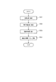
図5は、印刷装置9、及び、メンテナンスサーバー7の動作を示すフローチャートである。
図5の(A)は印刷装置9のステータスデータ生成部402の動作を示し、(B)は印刷装置9の間隔更新部403の動作を示し、(C)はメンテナンスサーバー7のステータスデータ受信部201を示し、(D)はメンテナンスサーバー7の応答部202を示し、(E)はメンテナンスサーバー7の分析部203の動作を示す。
Next, operations of the
FIG. 5 is a flowchart showing the operation of the
5A shows the operation of the status data generation unit 402 of the
図5の(A)に示すように、印刷装置9のステータスデータ生成部402は、送信間隔設定ファイル422を参照し、ステータスデータD1を生成するタイミングが到来したか否かを監視する(ステップSA1)。
送信間隔設定ファイル422は、ステータスデータD1を生成し、送信する間隔を示す情報が記述されたファイルである。ステップSA1において、ステータスデータ生成部402は、送信間隔設定ファイル422を参照し、前回、ステータスデータD1を生成し、送信した後、送信間隔設定ファイル422が示す間隔が経過した場合、ステータスデータD1を生成するタイミングが到来したと判別する。
As shown in FIG. 5A, the status data generation unit 402 of the
The transmission
ステータスデータD1を生成するタイミングが到来した場合(ステップSA1:YES)、ステータスデータ生成部402は、ログファイル421を参照して、ログファイル421に記述されたログ情報に基づいて処理装置状態情報を生成し、生成した処理装置状態情報に基づいて、ステータスデータD1を生成する(ステップSA2)。以下、ステップSA2の処理について詳述する。
When the timing to generate the status data D1 has come (step SA1: YES), the status data generation unit 402 refers to the
図6は、処理装置状態情報に含まれる情報を模式的に示す図である。
図6に示すように、処理装置状態情報は、印刷装置識別情報を含む。印刷装置識別情報とは、印刷装置9を一意に識別する識別情報であり、例えば、印刷装置9のシリアル番号(印刷装置9の製造時に、印刷装置9に一意に割り振られる番号)を印刷装置識別情報として用いることができる。
また、処理装置状態情報は、監視項目ごとに、ログ関連情報を備える。すなわち、処理装置状態情報は、監視項目:プリンターエラーのログ関連情報、監視項目:印刷ヘッド形成ライン累計数のログ関連情報、及び、監視項目:カッター使用累計数のログ関連情報を備える。
ログ関連情報は、対応する監視項目を識別する識別情報である監視項目識別情報と、対応する監視項目のログ情報である監視項目ログ情報とを備える。すなわち、監視項目:プリンターエラーのログ関連情報は、監視項目:プリンターエラーを識別する監視項目識別情報(以下、「プリンターエラー識別情報」という。)と、監視項目:プリンターエラーの監視項目ログ情報(以下、「プリンターエラーログ情報」という。)とを備える。監視項目:印刷ヘッド形成ライン累計数のログ関連情報は、監視項目:印刷ヘッド形成ライン累計数を識別する監視項目識別情報(以下、「印刷ヘッド形成ライン累計数」という。)と、監視項目:印刷ヘッド形成ライン累計数の監視項目ログ情報(以下、「印刷ヘッド形成ライン累計数ログ情報」という。)とを備える。監視項目:カッター使用累計数のログ関連情報は、監視項目:カッター使用累計数を識別する監視項目識別情報(以下、「カッター使用累計数識別情報」という。)と、監視項目:カッター使用累計数の監視項目ログ情報(以下、「カッター使用累計数ログ情報」という。)とを備える。
FIG. 6 is a view schematically showing information included in the processing device state information.
As shown in FIG. 6, the processing device status information includes printing device identification information. The printing apparatus identification information is identification information for uniquely identifying the
Further, the processing device state information includes log related information for each monitoring item. That is, the processing device status information includes monitoring items: log related information of printer error, monitoring items: log related information of print head forming line cumulative number, and monitoring item: cutter related cumulative number of log using information.
The log related information includes monitoring item identification information which is identification information for identifying a corresponding monitoring item, and monitoring item log information which is log information of the corresponding monitoring item. That is, the monitor item: printer error log related information is a monitor item: monitor item identification information for identifying a printer error (hereinafter referred to as "printer error identification information") and monitor item: printer error monitor item log information ( Hereinafter, it is referred to as “printer error log information”. Monitor item: Log related information of print head formation line total number is monitor item: Monitor item identification information identifying print head formation line total number (hereinafter referred to as "print head formation line total number") and monitor item: The monitor item log information of the print head formation line cumulative number (hereinafter referred to as “print head formation line cumulative number log information”) is provided. Monitoring items: Log related information on the cumulative number of cutter usage, monitoring item: Monitoring item identification information identifying the cumulative number of cutter usage (hereinafter referred to as "cutting cutter cumulative number identification information"), and monitoring item: cumulative number of cutter usage And monitoring item log information (hereinafter referred to as “cutter usage cumulative number log information”).
また、ステータスデータD1は、階層化されたキーと値との組み合わせによって、情報を階層化して記述可能なテキストデータ(例えば、XML(Extensible Markup Language)形式のデータ)であり、メンテナンスサーバー7にリクエストとして送信可能なデータである。 Further, the status data D1 is text data (for example, data in the XML (Extensible Markup Language) format) that can be described hierarchically by combining hierarchical keys and values (for example, data in the XML (Extensible Markup Language) format). It is data that can be transmitted as
図7は、ステータスデータD1の内容を説明に適した態様で模式的に示す図である。
ステータスデータD1は、ステータスデータD1を生成した印刷装置9が設けられた店舗を示す店舗識別情報を含む。店舗識別情報とは、店舗に一意に割り振られた識別情報である。印刷装置9のそれぞれには、各印刷装置9が設けられた店舗を示す店舗識別情報が事前に登録される。図7で例示するステータスデータD1では、領域A1に、店舗識別情報が記述される。
ステータスデータD1は、ステータスデータD1を生成した印刷装置9を示す印刷装置識別情報を含む。図7で例示するステータスデータD1では、領域A2に、印刷装置識別情報が記述される。
FIG. 7 is a view schematically showing the content of the status data D1 in a mode suitable for explanation.
The status data D1 includes store identification information indicating a store provided with the
The status data D1 includes printing device identification information indicating the
ステータスデータD1は、印刷装置ステータス情報が記述される。図7で例示するステータスデータD1では、領域A3に、印刷装置ステータス情報が記述される。
印刷装置ステータス情報は、各監視項目の監視項目識別情報と監視項目ログ情報との組み合わせを含む。図7で例示するステータスデータD1では、領域A31に、監視項目:プリンターエラーについての監視項目識別情報(プリンターエラー識別情報)と、監視項目ログ情報(プリンターエラーログ情報)とが記述される。また、領域A32に、監視項目:印刷ヘッド形成ライン累計数についての監視項目識別情報(印刷ヘッド形成ライン識別情報)と、監視項目ログ情報(印刷ヘッド形成ライン累計数ログ情報)とが記述される。また、領域A33に、監視項目:カッター使用累計数についての監視項目識別情報(カッター使用累計数識別情報)と、監視項目ログ情報(カッター使用累計数ログ情報)とが記述される。
The status data D1 describes printing apparatus status information. In the status data D1 illustrated in FIG. 7, printing apparatus status information is described in the area A3.
The printing apparatus status information includes a combination of monitoring item identification information of each monitoring item and monitoring item log information. In the status data D1 illustrated in FIG. 7, a monitoring item: monitoring item identification information (printer error identification information) for a printer error and monitoring item log information (printer error log information) are described in the area A31. Further, in the area A32, monitoring item identification information (print head forming line identification information) on the cumulative number of print head forming lines and monitoring item log information (print head forming line cumulative number log information) are described. . Further, in the area A33, monitoring item identification information (cutter usage cumulative number identification information) on the cumulative number of cutter usages and monitoring item log information (cutter usage cumulative number log information) are described.
以上のように、ステータスデータD1には、店舗識別情報と、印刷装置識別情報と、各監視項目の監視項目識別情報及び監視項目ログ情報の組み合わせと、が含まれる。 As described above, the status data D1 includes store identification information, printing apparatus identification information, and a combination of monitoring item identification information of each monitoring item and monitoring item log information.
図5の(A)に示すように、ステップSA2でステータスデータD1を生成した後、ステータスデータ生成部402は、印刷装置通信部43を制御して、生成したステータスデータD1をメンテナンスサーバー7に送信する(ステップSA3)。ステップSA3の処理は、「印刷装置9からサーバーに応答要求を送信する処理」に相当する。
ステップSA3において、ステータスデータ生成部402は、リクエストボディーにステータスデータD1が記述されたHTTPリクエストを、HTTPに従って、メンテナンスサーバー7に送信する。なお、ステータスデータD1を送信するメンテナンスサーバー7のURLや、使用するプロトコル等の、ステータスデータD1を応答要求としてメンテナンスサーバー7に送信するために必要な情報は、事前に登録される。
As shown in FIG. 5A, after the status data D1 is generated in step SA2, the status data generation unit 402 controls the printing
In step SA3, the status data generation unit 402 transmits an HTTP request in which status data D1 is described in the request body to the
ステータスデータD1の送信後、ステータスデータ生成部402は、処理手順をステップSA1に戻す。 After transmitting the status data D1, the status data generation unit 402 returns the processing procedure to step SA1.
図5の(C)に示すように、メンテナンスサーバー7のステータスデータ受信部201は、メンテナンスサーバー通信部22を制御して、ステータスデータD1を受信する(ステップSC1)。
次いで、ステータスデータ受信部201は、受信したステータスデータD1を、応答部202に出力し(ステップSC2)、分析部203に出力する(ステップSC3)。
As shown in FIG. 5C, the status
Next, the status
図5の(D)に示すように、応答部202は、ステータスデータ受信部201が出力したステータスデータD1を取得する(ステップSD1)。
次いで、応答部202は、通信許容量ファイル212を参照する(ステップSD2)。通信許容量ファイル212は、通信許容量算出部204によって後述する方法により、印刷装置9がステータスデータD1を送信する間隔である通信許容量を示す通信許容量情報が記述されたファイルである。
次いで、応答部202は、以下の方法で、応答データD2を生成する(ステップSD3)。
As shown in (D) of FIG. 5, the
Next, the
Next, the
応答データD2は、通信許容量情報、及び、所定の場合にはエラー時間隔情報を含むデータである。
ステップSD3において、応答部202は、通信許容量ファイル212に記述された通信許容量情報を取得し、応答データD2に含める。
また、ステップSD3において、応答部202は、印刷装置9にエラーが発生しているか否かを判別する。
本実施形態では、エラーとして、上述したプリンターエラーのほか、印刷ヘッドエラー、カッターエラーがある。
印刷ヘッドエラーとは、印刷ヘッド411による印刷ヘッド形成ライン累計数が、印刷ヘッド411の寿命を判定する基準となる所定の閾値を上回っている状態のことである。ステップSD3において、応答部202は、ステータスデータD1に含まれる印刷ヘッド形成ライン累計数ログ情報に基づいて、印刷ヘッド形成ライン累計数と、所定の閾値とを比較し、比較結果に基づいて、印刷ヘッドエラーが発生しているか否かを判別する。
カッターエラーとは、カッター412によるカッター使用累計数が、カッター412の寿命を判定する基準となる所定の閾値を上回っている状態のことである。ステップSD3において、応答部202は、ステータスデータD1に含まれるカッター使用累計数ログ情報に基づいて、カッター使用累計数と、所定の閾値とを比較し、比較結果に基づいて、カッターエラーが発生しているか否かを判別する。
なお、印刷装置9のエラー(クライアントのエラー)は、例示したものに限らない。
The response data D2 is data including communication allowance information and, in a predetermined case, error time interval information.
In step SD3, the
In step SD3, the
In the present embodiment, errors include print head errors and cutter errors in addition to the above-described printer errors.
The print head error is a state in which the total number of print head formation lines formed by the
The cutter error is a state in which the cumulative number of cutters used by the
The error of the printing apparatus 9 (error of the client) is not limited to the illustrated one.
プリンターエラー、印刷ヘッドエラー、カッターエラーのいずれも発生していない場合、応答部202は、応答データD2にエラー時間隔情報を含めず、ステップSD3の処理を終了する。
一方、プリンターエラー、印刷ヘッドエラー、カッターエラーのうち、1つでもエラーが発生している場合、応答部202は、エラー時間隔情報を生成する。
エラー時間隔情報とは、エラーが発生した状態の印刷装置9がステータスデータD1を送信する間隔(以下、「エラー発生時間隔」という。)を示す情報であり、エラー発生時間隔の値は、エラーが発生していない状態の印刷装置9がステータスデータD1を送信する間隔(以下、「通常時間隔」という。)の値よりも短い値とされる。すなわち、後述するように、エラーが発生していない状態の印刷装置9は、通信許容量情報が示す間隔(=通常時間隔)でステータスデータD1を送信するが、エラー発生時間隔は、通信許容量情報が示す間隔が取り得る値のいずれよりも小さい値とされる。
このように、エラー発生時間隔が、通常時間隔よりも短いことの理由については後述する。
なお、本実施形態では、発生したエラーの種類、及び、発生したエラーの状態に応じて、対応するエラー発生時間隔が予め定められており、エラー時間隔情報の生成に際し、応答部202は、発生したエラーの種類、及び、発生したエラーの状態に対応して予め定められたエラー発生時間隔を示す情報を生成する。
エラー時間隔情報を生成した後、応答部202は、応答データD2にエラー時間隔情報を含める。この結果、応答データD2には、通信許容量情報、及び、エラー時間隔情報が含まれた状態となる。
If none of the printer error, the print head error, and the cutter error has occurred, the
On the other hand, when at least one of the printer error, the print head error, and the cutter error has an error, the
The error interval information is information indicating an interval (hereinafter referred to as “error occurrence time interval”) at which the
Thus, the reason why the error occurrence time interval is shorter than the normal time interval will be described later.
In the present embodiment, the corresponding error occurrence time interval is determined in advance according to the type of error that has occurred and the state of the error that has occurred, and when generating the error time interval information, the
After generating the error interval information, the
ステップSD3で応答データD2を生成した後、応答部202は、メンテナンスサーバー通信部22を制御して、生成した応答データD2を、応答として、印刷装置9に送信する(ステップSD4)。例えば、応答部202は、レスポンスボディーに応答データD2が記述されたHTTPレスポンスを、HTTPに従って、印刷装置9に送信する。
ステップSD3の処理は、「サーバーがクライアントから受信した応答要求に応じてクライアントに応答を送信する処理」に相当する。
After generating the response data D2 in step SD3, the
The process of step SD3 corresponds to "the process of the server sending a response to the client in response to the response request received from the client".
図5の(B)に示すように、印刷装置9の間隔更新部403は、印刷装置通信部43を制御して、応答データD2を受信する(ステップSB1)。
次いで、間隔更新部403は、応答データD2に基づいて、送信間隔設定ファイル422を更新する(ステップSB2)。
詳述すると、応答データD2に、通信許容量情報が含まれ、エラー時間隔情報が含まれていない場合(=印刷装置9にエラーが発生していない場合)、間隔更新部403は、以下の方法で送信間隔設定ファイル422を更新する。すなわち、間隔更新部403は、応答データD2に含まれる通信許容量情報に基づいて、送信間隔設定ファイル422が示す間隔が、応答データD2に含まれる通信許容量情報が示す間隔(通信許容量)となるように、当該ファイルを更新する。
この結果、印刷装置9は、メンテナンスサーバー7が算出した通信許容量に対応する間隔で、ステータスデータD1を生成し、送信する。
As shown in FIG. 5B, the
Next, the
More specifically, when the response data D2 includes communication allowance information and does not include error interval information (= when an error does not occur in the printing apparatus 9), the
As a result, the
一方、応答データD2に、通信許容量情報、及び、エラー時間隔情報が含まれた状態の場合(=印刷装置9にエラーが発生した状態の場合)、間隔更新部403は、以下の方法で送信間隔設定ファイル422を更新する。すなわち、間隔更新部403は、応答データD2に含まれるエラー時間隔情報に基づいて、送信間隔設定ファイル422が示す間隔が、応答データD2に含まれるエラー時間隔情報が示す間隔(エラー発生時間隔)となるように、当該ファイルを更新する。
この結果、印刷装置9は、エラーが発生していない印刷装置9がステータスデータD1を送信する間隔よりも短い間隔で、ステータスデータD1を生成し、送信する。
これにより、以下の効果を奏する。
すなわち、印刷装置9にエラーが発生した状態の場合、保守担当者は、印刷装置9の状態の変化をできるだけ短い間隔で監視し、必要に応じて対応する処理を行う必要がある。そして、エラーが発生した印刷装置9がステータスデータD1を送信する間隔よりも、エラーが発生していない印刷装置9がステータスデータD1を送信する間隔よりも短くすることにより、後述するように、ステータスデータベース211において、エラーが発生した印刷装置9に対応するレコードが、エラーが発生していない印刷装置9に対応するレコードよりも、頻繁に更新されることにより、これにより、保守担当者が、印刷装置9の状態の変化をできるだけ短い間隔で監視し、必要に応じて対応する処理を行うことが可能となる。
On the other hand, when the response data D2 includes communication allowance information and error time interval information (= when an error occurs in the printing device 9), the
As a result, the
This produces the following effects.
That is, when an error occurs in the
なお、エラーが発生した印刷装置9は、ステータスデータD1の送信に関し、以下の処理を実行する。
すなわち、印刷装置9の間隔更新部403は、印刷装置9に発生したエラーの全てが解消したか否かを監視する。
そして、全てのエラーが解消した場合、間隔更新部403は、直近でメンテナンスサーバー7から受信した応答データD2に含まれる通信許容量情報に基づいて、送信間隔設定ファイル422が示す間隔が、通信許容量情報が示す間隔(通信許容量)となるように、当該ファイルを更新する。
このような処理が行われる結果、印刷装置9においてエラーが解消したのにもかかわらず、不必要に、印刷装置9がエラー発生時間隔でステータスデータD1を送信することを防止でき、より効果的にメンテナンスサーバー7の処理負荷の増大を抑制できる。
The
That is, the
Then, when all the errors have been eliminated, the
As a result of such processing being performed, it is possible to prevent the
一方、図5の(E)に示すように、分析部203は、ステータスデータ受信部201が出力したステータスデータD1を取得する(ステップSE1)。
次いで、分析部203は、取得したステータスデータD1に基づいて、ステータスデータベース211を更新する(ステップSE2)。以下、ステップSE2の処理について詳述する。
On the other hand, as shown in (E) of FIG. 5, the
Next, the
図8は、ステータスデータベース211のデータ構造を模式的に示す図である。
図8に示すように、ステータスデータベース211の1件のレコードは、少なくとも、印刷装置識別情報と、プリンターエラー有無情報と、印刷ヘッドエラー有無情報と、カッターエラー有無情報とを備える。
プリンターエラー有無情報とは、プリンターエラーが発生しているか否かを示す情報であり、発生していることを示す値(図8では「有」と表現。)、又は、発生していないことを示す値(図8では「無」と表現。)のいずれかの値を有する。
印刷ヘッドエラー有無情報とは、印刷ヘッドエラーが発生しているか否かを示す情報であり、発生していることを示す値(図8では「有」と表現。)、又は、発生していないことを示す値(図8では「無」と表現。)のいずれかの値を有する。
カッターエラー有無情報とは、カッターエラーが発生しているか否かを示す情報であり、発生していることを示す値(図8では「有」と表現。)、又は、発生していないことを示す値(図8では「無」と表現。)の何れかの値を有する。
FIG. 8 is a diagram schematically showing the data structure of the
As shown in FIG. 8, one record of the
The printer error presence / absence information is information indicating whether or not a printer error has occurred, and is a value indicating that it has occurred (expressed as “present” in FIG. 8) or that it has not occurred. It has one of the values shown (represented as “absent” in FIG. 8).
The print head error presence / absence information is information indicating whether or not a print head error has occurred, and is a value indicating that it has occurred (expressed as “present” in FIG. 8) or has not occurred. It has one of the value (it expresses as "absent" in FIG. 8) which shows that.
The cutter error presence / absence information is information indicating whether or not a cutter error has occurred, and is a value indicating that it has occurred (expressed as “present” in FIG. 8) or that it has not occurred. It has one of the values shown (expressed as “absent” in FIG. 8).
ステップSE2において、分析部203は、ステータスデータD1に含まれる印刷装置ステータス情報を取得する。上述したように、印刷装置ステータス情報には、各監視項目の監視項目識別情報と監視項目ログ情報との組み合わせが含まれる。
次いで、分析部203は、印刷装置識別情報の突合により、ステータスデータベース211のレコードのうち、対応するレコード(ステータスデータD1の印刷装置識別情報の値と同一の値の印刷装置識別情報を有するレコード)を特定する。次いで、分析部203は、取得した印刷装置ステータス情報に基づいて、特定したレコードのプリンターエラー有無情報、印刷ヘッドエラー有無情報、及び、カッターエラー有無情報を更新する。
具体的には、分析部203は、印刷装置ステータス情報に含まれるプリンターエラーログ情報(監視項目ログ情報)に基づいて、プリンターエラーが発生しているか否かを判別し、発生している場合はプリンターエラー有無情報の値を、発生していることを示す値へと更新し、発生していない場合はプリンターエラー有無情報の値を、発生していないことを示す値へと変更する。また、分析部203は、印刷装置ステータス情報に含まれる印刷ヘッド形成ライン累計数ログ情報(監視項目ログ情報)に基づいて、印刷ヘッド形成ライン累計数が所定の閾値を上回るか否かを判別し、上回る場合は印刷ヘッドエラー有無情報の値を、印刷ヘッドエラーが発生していることを示す値へと更新し、上回らない場合は印刷ヘッドエラー有無情報の値を、印刷ヘッドエラーが発生していないことを示す値へと更新する。また、分析部203は、印刷装置ステータス情報に含まれるカッター使用累計数ログ情報(監視項目ログ情報)に基づいて、カッター使用累計数が所定の閾値を上回るか否かを判別し、上回る場合はカッターエラー有無情報の値を、カッターエラーが発生していることを示す値へと更新し、上回らない場合はカッターエラー有無情報の値を、カッターエラーが発生していないことを示す値へと更新する。
In step SE2, the
Next, the
Specifically, the
次に、通信許容量算出部204が通信許容量ファイル212を更新するときの処理について説明する。
ここで、上述したように、メンテナンスサーバー7には、複数の印刷装置9が接続されるが、メンテナンスサーバー7に接続される印刷装置9の数は、ネットワークシステム1の規模によっては多大(例えば、1000台を超える台数)となる可能性がある。そして、印刷装置9からの応答要求(ステータスデータD1)の送信が短時間に高密度で行われると、メンテナンスサーバー7の処理負荷が増大し、メンテナンスサーバー7における処理の遅延が発生する可能性がある。
以上を踏まえ、通信許容量算出部204は、以下の処理を行って適切な値の通信許容量を算出し、各印刷装置9による応答要求の送信が短時間に高密度で行われることを抑制し、メンテナンスサーバー7の処理負荷の増大を抑制する。
Next, a process when the communication
Here, as described above, the plurality of
Based on the above, the communication
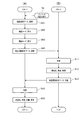
図9は、通信許容量ファイル212を更新するときの通信許容量算出部204の動作を示すフローチャートである。
通信許容量算出部204は、図9のフローチャートの処理を、所定の間隔で実行する。
図9に示すように、通信許容量算出部204は、メンテナンスサーバー7に接続された印刷装置9の数を取得する(ステップSG1)。ここで、通信許容量算出部204は、印刷装置9との間で確立した通信経路(本例では、TCPコネクション上のHTTPセッション)の数を管理しており、通信経路の数に基づいて、メンテナンスサーバー7に接続された印刷装置9の数を取得する。以下、メンテナンスサーバー7に接続された印刷装置9の数のことを「接続台数」と表現する。
FIG. 9 is a flowchart showing the operation of the communication
The communication
As shown in FIG. 9, the communication
次いで、通信許容量算出部204は、処理可能回数を算出する(ステップSG2)。
処理可能回数は、メンテナンスサーバー7のCPU、その他の制御主体(以下、単に「CPU」と表現する。)の使用率が最大値の場合に、単位時間である1秒あたりに、メンテナンスサーバー7が処理可能なステータスデータD1の数のことである。
なお、CPUの使用率の最大値は、ステータスデータD1の処理、その他の付随する処理を遅延なくメンテナンスサーバー7が実行可能な値に設定されており、CPUの使用率が、当該最大値を上回ると、メンテナンスサーバー7の処理に遅延が生じる可能性がある。従って、ステータスデータD1の処理にあたり、CPUの使用率が当該最大値を上回らないことが求められ、後に明らかとなるとおり、通信許容量は、CPUの使用率が当該最大値を上回らないことを実現できる適切な値とされる。
ステップSG2において、通信許容量算出部204は、ステータスデータD1のデータ量を取得する。通信許容量算出部204は、現時点から遡って所定の期間に受信したステータスデータD1のデータ量の平均値を算出する機能を有し、当該機能によって算出した平均値を、ステータスデータD1のデータ量として取得する。なお、ステータスデータD1のデータ量は、事前のテストやシミュレーションに基づいて定められた固定値でもよい。次いで、通信許容量算出部204は、取得したステータスデータD1のデータ量に基づいて、ステータスデータD1の処理に要する時間を算出する。ステータスデータD1の処理とは、上述した応答部202による処理や、分析部203による処理、その他のステータスデータD1に基づいて実行される処理のことである。ステータスデータD1のデータ量と、ステータスデータD1の処理に要する時間とは正の相関関係にあり、メンテナンスサーバー7には、当該データ量と当該時間との対応関係を示すテーブルが事前に登録される。ステータスデータD1の処理に要する時間の算出方法は例示した方法に限らずどのような方法であってもよい。
次いで、通信許容量算出部204は、算出したステータスデータD1の処理に要する時間に基づいて、単位時間あたりにメンテナンスサーバー7が処理可能なステータスデータD1の数(処理可能回数)を算出する。
Next, the communication allowable
When the usage rate of the CPU of the
The maximum value of the CPU usage rate is set to a value that the
In step SG2, the communication
Next, the communication
ステップSG1で接続台数を算出し、ステップSG2で処理可能回数を算出した後、通信許容量算出部204は、以下の式S1により、通信許容量を算出する(ステップSG3)。「式S1:通信許容量=接続台数/処理可能回数」。
以上のようにして算出された通信許容量が示す間隔で、メンテナンスサーバー7に接続された複数の印刷装置9がステータスデータD1を送信した場合、メンテナンスサーバー7は、CPUの使用率が最大値を上回ることなく、受信した複数のステータスデータD1を処理できる。
なお、例示した通信許容量の算出方法は、説明の便宜を考慮して単純化しているが、通信許容量の算出にあたり、各種マージンを反映してもよいことは勿論である。また、接続台数は、メンテナンスサーバー7に接続された印刷装置9の数であったが、印刷装置9のほかのメンテナンスサーバー7に接続される装置を反映した数であってもよい。
また、通信許容量の算出方法は例示した方法に限らない。すなわち、通信許容量は、メンテナンスサーバー7の処理負荷の増大を抑制するという観点から、メンテナンスサーバー7の処理負荷に影響を与える要素に基づいて算出されるものであれば、その方法は何であってもよい。また、メンテナンスサーバー7の処理負荷に影響を与える要素について、「メンテナンスサーバー7に接続された印刷装置9の数」、「メンテナンスサーバー7の処理能力」、「ステータスデータD1(印刷装置9から応答要求として受信するデータのデータ量)」、及び、「ステータスデータD1の処理に要する時間」を例示したが、当該要素は例示したものに限らない。
After the number of connected devices is calculated in step SG1 and the processable number is calculated in step SG2, the communication
When the plurality of
In addition, although the calculation method of the illustrated communication allowance is simplified in consideration of the convenience of description, it goes without saying that various margins may be reflected in the calculation of the communication allowance. Further, although the number of connected devices is the number of
Further, the method of calculating the communication allowance is not limited to the illustrated method. That is, from the viewpoint of suppressing the increase of the processing load of the
ステップSG3で通信許容量を算出した後、通信許容量算出部204は、通信許容量ファイル212に記述された通信許容量情報の値を、算出した通信許容量に書き換えることによって、通信許容量ファイル212を更新する(ステップSG4)。
After calculating the communication allowance in step SG3, the communication
次に、保守担当者(上述したように、店舗システム3の印刷装置9の保守を担当する者を意味する。)に対して、印刷装置9の保守のために有益な情報を提供するときのメンテナンスサーバー7の動作について説明する。
なお、以下の説明では、保守担当者は、本社に勤務し本社端末5を利用する者とする。
まず、特定の印刷装置9に関する情報を取得することを望む保守担当者は、本社端末5のブラウザーを立ち上げ、予め定められたメンテナンスサーバー7の所定のURLにアクセスさせる。
メンテナンスサーバー7の情報提供部205は、所定のURLへのアクセスに応じて、印刷装置識別情報入力画面G101(図10)を表示させるHTTPファイルを生成し、本社端末5に送信する。
本社端末5の本社端末制御部30は、ブラウザーの機能により、HTTPファイルを受信し、受信したHTTPファイルに基づいて本社端末表示部33を制御して、表示パネルに印刷装置識別情報入力画面G101を表示させる。
Next, when providing useful information for maintenance of the
In the following description, a person in charge of maintenance is a person who works at the head office and uses the
First, a maintenance person who wants to acquire information on a
The
The head office
図10は、印刷装置識別情報入力画面G101を示す図である。
図10に示すように、印刷装置識別情報入力画面G101は、印刷装置識別情報を入力可能な入力欄R101を備える。保守担当者は、入力欄R101に、情報を取得することを望む印刷装置9の印刷装置識別情報を入力し、確定ボタンB101を操作することにより、入力を確定する。入力の確定に応じて、HTTPファイルに実装されたスクリプトの機能により、入力された印刷装置識別情報が、メンテナンスサーバー7に送信される。
FIG. 10 is a diagram showing the printing apparatus identification information input screen G101.
As shown in FIG. 10, the printing apparatus identification information input screen G101 includes an input field R101 in which printing apparatus identification information can be input. The maintenance staff inputs the printing apparatus identification information of the
メンテナンスサーバー7の情報提供部205は、印刷装置識別情報を受信する。次いで、情報提供部205は、受信した印刷装置識別情報に基づいて、ステータスデータベース211の対応するレコードを特定する。対応するレコードとは、受信した印刷装置識別情報の値と同一の値の印刷装置識別情報を有するレコードのことである。次いで、情報提供部205は、特定したレコードに基づいて、情報提供画面G111(図11)を表示させるHTTPファイルを生成し、本社端末5に送信する。
本社端末5の本社端末制御部30は、ブラウザーの機能により、HTTPファイルを受信し、受信したHTTPファイルに基づいて本社端末表示部33を制御して、表示パネルに情報提供画面G111を表示させる。
The
The head office
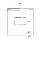
図11は、情報提供画面G111を示す図である。
図11に示すように、情報提供画面G111は、領域A111と、領域A112とを有する。
領域A111には、保守担当者が入力した印刷装置識別情報の印刷装置9に関する基礎的な情報が表示される。図11の例では、印刷装置9に関する基礎的な情報は、印刷装置9の型番を示す情報、印刷装置9にインストールされたファームウェアのバージョンを示す情報、印刷装置9が設けられた店舗の名称を示す情報、当該店舗の住所を示す情報、当該店舗の電話番号を示す情報、及び、印刷装置9が設けられたレジカウンターのレーンの番号を示す情報である。印刷装置9に関する基礎的な情報は例示した情報に限らない。
ここで、メンテナンスサーバー7のメンテナンスサーバー記憶部21には、各印刷装置について、印刷装置識別情報と、印刷装置に関する基礎的な情報とを対応付けて記憶するデータベースが記憶される。情報提供部205は、当該データベースに基づいて、印刷装置に関する基礎的な情報を取得する。
保守担当者は、情報提供画面G111の領域A111に表示された情報を参照することにより、印刷装置9に関する基礎的な情報を取得することができ、必要に応じて、店舗への電話等の作業を行うことができる。
FIG. 11 is a diagram showing the information provision screen G111.
As shown in FIG. 11, the information provision screen G111 has an area A111 and an area A112.
The area A 111 displays basic information on the
Here, the maintenance
The maintenance staff can acquire basic information on the
図11に示すように、領域A112には、プリンターエラーの発生の有無を示す情報、印刷ヘッドエラーの発生の有無を示す情報、及び、カッターエラーの発生の有無を示す情報が表示される。
保守担当者は、領域A112に表示された情報を参照することにより、プリンターエラー、印刷ヘッドエラー、及び、カッターエラーのそれぞれについて、発生しているか否かを認識でき、当該認識に基づいて対応する作業を行うことができる。対応する作業とは、例えば、エラーが発生している場合に、店舗の責任者に、エラーが発生していること、及び、エラーに対応して行うべき作業を連絡することである。
As shown in FIG. 11, in the area A112, information indicating the presence or absence of a printer error, information indicating the presence or absence of a print head error, and information indicating the presence or absence of a cutter error are displayed.
By referring to the information displayed in the area A112, the maintenance staff can recognize whether each of the printer error, the print head error, and the cutter error has occurred, and respond based on the recognition. Work can be done. The corresponding operation is, for example, when an error occurs, notifying the store manager that the error has occurred and the operation to be performed in response to the error.
次に、店舗に設置された印刷装置9の電源がオンされた場合の、印刷装置9の動作について説明する。
図12は、電源がオンされた場合の印刷装置9、及び、POSサーバー10の動作を示すフローチャートである。図12の(A)は印刷装置9の動作を示し、(B)はPOSサーバー10の動作を示す。
Next, the operation of the
FIG. 12 is a flowchart showing the operation of the
レジ担当者は、印刷装置9の電源をオンする(ステップS1)。本例では、印刷装置9は、レジカウンターに設置された状態であり、レジ担当者は、例えば、店舗の開店時に印刷装置9の電源をオンする。本実施形態では、印刷装置9の電源のオンに応じて、自動で、ブラウザーが起動する。
The cashier person turns on the power of the printing apparatus 9 (step S1). In this example, the
図12の(A)に示すように、印刷装置9の印刷制御部404は、POSサーバー10の所定のURLにアクセスする(ステップSH1)。POSサーバー10のURLや、POSサーバー10との通信で送受信するデータのフォーマット、その他のPOSサーバー10との間で通信を行うのに必要な情報は、印刷装置9に予め登録される。
As shown in FIG. 12A, the
図12の(B)に示すように、印刷装置9からの所定のURLへのアクセスに応じて、POSサーバー10の会計関連処理実行部501は、POSサーバー通信部52を制御して、所定のHTMLファイルを印刷装置9に送信する(ステップSI1)。所定のHTMLファイルは、少なくとも後述する会計用ユーザーインターフェース70を表示させる機能を有するHTMLファイルである。
As shown in FIG. 12B, in response to the access to the predetermined URL from the
図12の(A)に示すように、印刷装置9の印刷制御部404は、印刷装置通信部43を制御して、所定のHTMLファイルを受信し、取得する(ステップSH2)。
次いで、印刷制御部404は、取得した所定のHTMLファイルを実行して、会計用ユーザーインターフェース70(図13)をタッチパネルTPに表示する(ステップSH3)。
As shown in FIG. 12A, the
Next, the
図13は、タッチパネルTPに表示された会計用ユーザーインターフェース70の一例を示す図である。
図13の会計用ユーザーインターフェース70において、左上部には、顧客が購入した商品の商品名、商品の単価、及び、商品の数量が一覧表示される一覧表示エリア71が設けられる。一覧表示エリア71の右方には、顧客が購入した商品の合計金額、会計に際して顧客から預かった貨幣の金額、及び、顧客に渡す釣銭の金額が表示される金額表示エリア72が設けられる。
一覧表示エリア71の下方には、バーコードスキャナーBSによって読み取られたバーコードの情報(以下、「バーコード情報」という。)が表示されるバーコード情報表示エリア73が設けられる。バーコード情報は、基本的には、商品に割り当てられた商品コードである。
バーコード情報表示エリア73の右方には、ソフトウェアテンキー74が設けられる。ソフトウェアテンキー74は、会計を確定する確定キー741、及び、小計(顧客が購入した商品の合計金額の計算)を指示する小計キー742を有する。
FIG. 13 is a diagram showing an example of the
In the
Below the
A software ten key 74 is provided on the right side of the barcode information display area 73. The software
以後、レジカウンターにおいて、レジ担当者は、会計用ユーザーインターフェース70を用いて、会計を行う。
このように、印刷装置9の電源のオンに応じて、印刷装置9のタッチパネルTPにレジカウンターで行われる会計(業務)で使用する会計用ユーザーインターフェース70が自動で表示される。このため、レジ担当者は、印刷装置9の電源のオン時に、POSサーバー10のURLへの入力等の作業を行う必要がなく、レジ担当者の作業効率が良く、利便性が高い。
Thereafter, at the checkout counter, the checkout clerk performs accounting using the
As described above, when the power of the
次に、レジカウンターでの会計に応じて印刷装置9が行う会計処理について詳述する。
Next, the accounting process performed by the
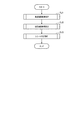
図14は、会計処理の実行時の印刷装置9の動作を示すフローチャートである。
図14に示すように、会計処理において、印刷装置9の印刷制御部404は、商品情報取得処理を実行する(ステップSJ1)。
商品情報取得処理において、印刷制御部404は、顧客が購入した商品ごとに、POSサーバー10と通信して、商品の商品名、及び、商品の単価(以下、「商品関連情報」という。)を取得し、取得した商品関連情報に基づく処理を実行する。以下、商品情報取得処理について詳述する。
FIG. 14 is a flowchart showing the operation of the
As shown in FIG. 14, in the accounting process, the
In the product information acquisition process, the
図15は、商品情報取得処理の実行時の印刷装置9の動作、及び、POSサーバー10の動作を示すフローチャートである。図15の(A)は、印刷装置9の動作を示し、(B)は、POSサーバー10の動作を示す。
FIG. 15 is a flowchart showing the operation of the
レジカウンターにおける会計において、レジ担当者は、バーコードスキャナーBSによって、顧客が購入する商品や商品の包装等に付されたバーコードを読み取る(ステップS2)。バーコードの読み取りに応じて、バーコードスキャナーBSは、読取結果に基づくデータ(以下、「読取結果データ」という。)を、バーコードスキャナーBSが接続されたポートを介して、印刷装置9の印刷装置デバイス通信部44に出力する。印刷装置デバイス通信部44は、読取結果データを、印刷装置制御部40に出力する。
読取結果データは、商品の商品コードを示す情報を含むデータである。
In the checkout counter, the cashier in charge reads the barcode attached to the product purchased by the customer or the package of the product by the barcode scanner BS (step S2). In response to the reading of the barcode, the barcode scanner BS prints data based on the reading result (hereinafter referred to as “reading result data”) through the port to which the barcode scanner BS is connected. The data is output to the
The reading result data is data including information indicating a product code of a product.
図15の(A)に示すように、印刷装置9の印刷装置制御部40の印刷制御部404は、印刷装置デバイス通信部44からの入力に基づいて、読取結果データを取得する(ステップSK1)。
次いで、印刷制御部404は、読取結果データに基づいて、商品コードを取得する(ステップSK2)。
次いで、印刷制御部404は、会計用ユーザーインターフェース70のバーコード情報表示エリア73にステップSK2で取得した商品コードを表示する(ステップSK3)。
次いで、印刷制御部404は、印刷装置通信部43を制御して、ステップSK2で取得した商品コードの商品の商品名、及び、商品の単価を問い合わせるデータ(以下、「商品情報要求データ」という。)を、POSサーバー10に送信する(ステップSK4)。
As shown in FIG. 15A, the
Next, the
Next, the
Next, the
図15の(B)に示すように、POSサーバー10の会計関連処理実行部501は、POSサーバー通信部52を制御して、商品情報要求データを受信する(ステップSL1)。
次いで、会計関連処理実行部501は、受信した商品情報要求データに基づいて、商品コードを取得し、POSサーバー記憶部51が記憶する商品マスター511を参照し、取得した商品コードの商品の商品名、及び、商品の単価を取得する(ステップSL2)。
As shown in FIG. 15B, the accounting-related
Next, the accounting-related
次いで、会計関連処理実行部501は、POSサーバー通信部52を制御して、ステップSL2で取得した商品の商品名、及び、商品の単価を示す商品情報応答データを印刷装置9に送信する(ステップSL3)。
Next, the accounting-related
図15の(A)に示すように、印刷装置9の印刷制御部404は、印刷装置通信部43を制御して、商品情報応答データを受信する(ステップSK5)。
次いで、印刷制御部404は、受信した商品情報応答データに基づいて、商品の商品名、及び、商品の単価を取得し、会計用ユーザーインターフェース70の一覧表示エリア71の対応する領域に、商品の商品名、商品の単価、及び、商品の数量の組み合わせを表示する(ステップSK6)。
As shown in FIG. 15A, the
Next, the
図14のフローチャートのステップSJ1の商品情報取得処理において、顧客が購入する商品のそれぞれについて、レジ担当者によりバーコードスキャナーBSによるバーコードの読み取りが行われ、バーコードの読み取りに応じて、印刷装置9、及び、POSサーバー10により図15のフローチャートで示す処理が実行される。
全ての商品のバーコードの読み取り、及び、読み取りに応じた各装置の処理が完了すると、図14のステップSJ1の商品情報取得処理が完了する。
全ての商品のバーコードの読み取り、及び、読み取りに応じた各装置の処理が完了すると、一覧表示エリア71に、顧客が購入する商品の商品名、単価、及び、数量の組み合わせが一覧表示された状態となる。
In the product information acquisition process of step SJ1 in the flowchart of FIG. 14, the cashier reads the barcode by the barcode scanner BS for each of the products purchased by the customer, and the printing apparatus is read according to the barcode read. 9 and the
When the barcodes of all the products are read and the processing of each device according to the reading is completed, the product information acquisition process of step SJ1 of FIG. 14 is completed.
When reading of the barcodes of all the products and processing of each device according to the reading are completed, the
図14に示すように、ステップSJ1の商品情報取得処理の実行後、印刷制御部404は、会計金額取得処理を実行する(ステップSJ2)。ステップSJ2の会計金額取得処理において、印刷制御部404は、顧客が購入した商品の合計金額を取得し、顧客の支払いに応じて顧客に渡す釣銭の金額を取得する。以下、会計金額取得処理について詳述する。
As shown in FIG. 14, after execution of the product information acquisition process of step SJ1, the
図16は、会計金額取得処理の実行時の印刷装置9の動作、及び、対応するPOSサーバー10の動作を示すフローチャートである。図16の(A)は、印刷装置9の動作を示し、(B)は、POSサーバー10の動作を示す。
FIG. 16 is a flowchart showing the operation of the
全ての商品のバーコードの読み取りが完了すると、レジ担当者は、ソフトウェアテンキー74の小計キー742を操作する(ステップS3)。
図16の(A)に示すように、小計キー742が操作されたことを検出すると、印刷装置9の印刷制御部404は、小計の計算を要求する小計計算要求データを生成し、印刷装置通信部43を制御して、POSサーバー10に送信する(ステップSM1)。
When reading of the barcodes of all the products is completed, the cashier staff operates the
As shown in FIG. 16A, when it is detected that the
図16の(B)に示すように、POSサーバー10の会計関連処理実行部501は、POSサーバー通信部52を制御して、小計計算要求データを受信する(ステップSN1)。
次いで、会計関連処理実行部501は、受信した小計計算要求データに基づいて、小計を計算する(ステップSN2)。なお、会計関連処理実行部501は、印刷装置9から受信した商品情報応答要求データ、その他付随するデータに基づいて、顧客が購入した商品の商品コードを管理する。ステップSN2において、会計関連処理実行部501は、管理する商品コードに基づいて、適宜、商品マスター511を参照し、小計(顧客が購入した商品の合計金額)を計算する。小計を計算する方法は、上述した方法に限らず、どのような方法でもよい。
As shown in FIG. 16B, the accounting-related
Next, the accounting-related
次いで、会計関連処理実行部501は、計算した小計を示す小計応答データを印刷装置9に送信する(ステップSN3)。
Next, the accounting-related
図16の(A)に示すように、印刷装置9の印刷制御部404は、印刷装置通信部43を制御して、小計応答データを受信する(ステップSM2)。
次いで、印刷制御部404は、受信した小計応答データに基づいて、金額表示エリア72の対応する領域に、小計(顧客が購入した商品の合計金額)を表示する(ステップSM3)。
As shown in FIG. 16A, the
Next, based on the received subtotal response data, the
小計が金額表示エリア72に表示されると、顧客は、金銭をレジ担当者に引き渡す。レジ担当者は、顧客から金銭を受け取り、ソフトウェアテンキー74に受け取った金銭の額を入力し、確定キー741を操作する(ステップS4)。確定キー741が操作されたことを検出すると、印刷制御部404は、顧客から受け取った金銭の額を金額表示エリア72の対応する領域に表示する。
さらに、確定キー741が操作されたことを検出すると、印刷制御部404は、釣銭の額の計算を要求する釣銭計算要求データをPOSサーバー10に送信する(ステップSM4)。
When the subtotal is displayed in the
Further, when it is detected that the
図16の(B)に示すように、POSサーバー10の会計関連処理実行部501は、POSサーバー通信部52を制御して、釣銭計算要求データを受信する(ステップSN4)。
次いで、会計関連処理実行部501は、釣銭の額を計算する(ステップSN5)。
次いで、会計関連処理実行部501は、計算した釣銭の額を示す釣銭応答データを印刷装置9に送信する(ステップSN6)。
As shown in FIG. 16B, the accounting-related
Next, the accounting-related
Next, the accounting-related
図16の(A)に示すように、印刷装置9の印刷制御部404は、印刷装置通信部43を制御して、釣銭応答データを受信する(ステップSM5)。
次いで、印刷制御部404は、受信した釣銭応答データに基づいて、金額表示エリア72の対応する領域に、釣銭の額を表示する(ステップSM6)。
レジ担当者は、金額表示エリア72に表示された釣銭の額に基づいて、顧客に対して釣銭を引き渡す。
As shown in FIG. 16A, the
Next, the
Based on the amount of change displayed in the
以上のように、ステップSJ2の会計金額取得処理において、印刷制御部404は、顧客が購入した商品の合計金額を取得し、顧客の支払いに応じて顧客に渡す釣銭の金額を取得する。
As described above, in the accounting amount acquisition process in step SJ2, the
図14に示すように、会計金額取得処理の実行後、印刷制御部404は、レシート発行処理を実行する(ステップSJ3)。ステップSJ3のレシート発行処理において、印刷制御部404は、POSサーバー10と通信し、顧客が購入した商品に関する情報や、顧客が購入した商品の合計金額を示す情報等が印刷されたレシートを発行する。以下、レシート発行処理について詳述する。
As shown in FIG. 14, after execution of the accounting amount acquisition processing, the
図17は、レシート発行処理の実行時の印刷装置9の動作、及び、POSサーバー10の動作を示すフローチャートである。図17の(A)は印刷装置9の動作を示し、(B)はPOSサーバー10の動作を示す。
FIG. 17 is a flowchart showing the operation of the
図17の(A)に示すように、会計金額取得処理が終了すると、印刷装置9の印刷制御部404は、会計情報を取得する(ステップSO1)。
会計情報は、会計ごとに一意に付与される識別情報(以下、「会計識別情報」という。)と、顧客が購入した商品のそれぞれの商品コード、商品名、単価、数量の組み合わせを示す情報(以下、「購入商品情報」という。)と、合計購入金額(小計)、顧客から受け取った貨幣の金額、及び、顧客に引き渡した釣銭の金額を示す情報(以下、「会計金額情報」という。)と、会計が行われた時刻を示す情報(以下、「会計時刻情報」という。)と、会計が行われた店舗の店舗識別情報と、を含む情報である。
なお、会計中、印刷制御部404は、購入商品情報に含まれる情報、及び、会計金額情報に含まれる情報を、所定の記憶領域に記憶する。ステップSO1において、印刷制御部404は、当該所定の記憶領域に記憶した情報に基づいて、購入商品情報、及び、会計金額情報を取得する。
また、会計時刻情報が示す会計が行われた時刻は、確定キー741が操作された時刻である。会計時刻情報が示す会計が行われた時刻は、確定キー741が操作された時刻に限らず、会計に際して1つ目の商品のバーコードが読み取られた時刻等、会計に由来する時刻であればよい。
また、印刷制御部404は、会計に応じて、会計識別情報を生成する機能を有し、当該機能に基づいて、会計識別情報を生成する。会計識別情報の値は、各店舗で行われる会計のそれぞれについて、一意な値とされる。
As shown in FIG. 17A, when the accounting amount acquisition process ends, the
The accounting information is information indicating a combination of identification information (hereinafter referred to as "accounting identification information") uniquely assigned to each account and a product code, a product name, a unit price, and a quantity of products purchased by the customer ((1) Hereinafter, referred to as “purchased product information.”, Total purchase price (subtotal), money amount of money received from the customer, and information indicating money amount of change delivered to the customer (hereinafter referred to as “accounting money information”). And information indicating the time when the accounting was performed (hereinafter referred to as “accounting time information”) and the store identification information of the store where the accounting has been performed.
During accounting, the
Further, the time when the accounting indicated by the accounting time information is performed is the time when the
The
会計情報の取得後、印刷制御部404は、印刷装置通信部43を制御して、取得した会計情報を示す会計情報データをPOSサーバー10に送信する(ステップSO2)。
After acquiring the accounting information, the
図17の(B)に示すように、POSサーバー10の会計関連処理実行部501は、POSサーバー通信部52を制御して、会計情報データを受信する(ステップSP1)。
次いで、会計関連処理実行部501は、受信した会計情報データが示す会計情報に基づいて、所定のレイアウトのレシートの発行を指示する記録データを生成する(ステップSP2)。
記録データは、所定のレイアウトに従って、いわゆるトップロゴや、ボトムロゴ、会計識別情報、会計が行われた時刻、顧客が購入した商品の商品名、単価、数量、合計購入金額、顧客から受け取った貨幣の金額、顧客に引き渡した釣銭の金額等が記録されたレシートの発行を指示する制御データである。記録データは、XMLのフォーマットに従って情報が記述されたXMLドキュメントである。
As shown in FIG. 17B, the accounting-related
Next, based on the accounting information indicated by the received accounting information data, the accounting-related
The recorded data are in accordance with a predetermined layout, so-called top logo, bottom logo, accounting identification information, time when accounting was performed, product name of the product purchased by the customer, unit price, quantity, total purchase price, money received from the customer It is control data for instructing issuance of a receipt in which the amount of money, the amount of money of change sent to the customer, and the like are recorded. Recording data is an XML document in which information is described according to the XML format.
次いで、会計関連処理実行部501は、POSサーバー通信部52を制御して、生成した記録データを、印刷装置9に送信する(ステップSP3)。
Next, the accounting-related
また、会計関連処理実行部501は、ステップSP1で会計情報データを受信した後、POSサーバー記憶部51が記憶する会計情報管理データベース512にアクセスする(ステップSP4)。
会計情報管理データベース512の1件のレコードは、会計識別情報と、購入商品情報と、会計金額情報と、会計時刻情報と、店舗識別情報と、を関連付けて記憶する。
次いで、ステップSP1で受信した会計情報データに基づいて、会計情報管理データベース512に、会計識別情報と、購入商品情報と、会計金額情報と、会計時刻情報と、店舗識別情報とを関連付けた1件のレコードを生成する(ステップSP5)。
このように、POSサーバー10は、会計に応じた会計情報を累積的に記憶する。これにより、店舗ごとの売上や、店舗における商品ごとの売り上げを管理できる。
Further, after receiving the accounting information data in step SP1, the accounting related
One record of the accounting
Next, based on the accounting information data received in step SP1, the accounting
Thus, the
図17の(A)に示すように、印刷装置9の印刷制御部404は、印刷装置通信部43を制御して記録データを受信する(ステップSO3)。
次いで、印刷制御部404は、XMLドキュメントの記録データに基づいて、印刷装置印刷部41が対応するコマンド体系の記録コマンドを生成する(ステップSO4)。
次いで、印刷制御部404は、生成した記録コマンドに基づいて、印刷装置印刷部41を制御して、レシートを発行する(ステップSO5)。
ステップSO5で発行されたレシートは、レジ担当者により、顧客に引き渡される。
As shown in FIG. 17A, the
Next, the
Next, the
The receipt issued at step SO5 is delivered to the customer by the cashier.
以上のように、本実施形態では、会計に応じて、印刷装置9が、POSサーバー10の機能を利用して会計処理を行ってレシートを発行する。また、POSサーバー10は、会計処理に基づく会計情報を累積に記憶する。
As described above, in the present embodiment, the
以上説明したように、本実施形態に係るネットワークシステム1は、所定の間隔で応答要求を送信する印刷装置9(クライアント)と、印刷装置9にネットワークを介して接続され、印刷装置9から受信した応答要求に応じて印刷装置9に応答を送信するメンテナンスサーバー7(サーバー)とを備える。そして、印刷装置9は、所定の間隔で、印刷装置9の状態を示すステータスデータD1を、応答要求として、メンテナンスサーバー7に送信し、メンテナンスサーバー7は、ステータスデータD1に基づいて、印刷装置9にエラーが発生しているか否かを判別し、エラーが発生していない場合は、メンテナンスサーバー7の処理負荷に影響を与える要素に基づいて、印刷装置9がステータスデータD1を送信する間隔を示す通信許容量を算出し、算出した通信許容量を示す通信許容量情報を、応答として、印刷装置9に送信し、エラーが発生している場合は、エラーが発生していない印刷装置9がステータスデータD1を送信する間隔よりも短い間隔を示すエラー時間隔情報を、応答として、印刷装置9に送信し、印刷装置9は、メンテナンスサーバー7から受信した通信許容量情報が示す間隔、又は、エラー時間隔情報が示す間隔に対応する間隔で、ステータスデータD1を送信する。
この構成によれば、印刷装置9は、メンテナンスサーバー7に対して、当該サーバーにおける処理負荷に影響を与える要素に基づいて算出された通信許容量が示す間隔で応答要求を送信するため、印刷装置9からメンテナンスサーバー7に対して応答要求(ステータスデータD1)が短時間に高密度で行われることを防止でき、応答要求が短時間に高密度で行われることに起因してメンテナンスサーバー7の処理負荷が増大し、メンテナンスサーバー7における処理の遅延が発生することを抑制できる。さらに、エラーが発生している印刷装置9は、エラーが発生していない印刷装置9よりも、短い間隔でステータスデータD1を送信するため、メンテナンスサーバー7によって、エラーが発生している印刷装置9の状態の変化を、短い間隔で監視できる。すなわち、印刷装置9と、メンテナンスサーバー7との間で、印刷装置9の状態に対応した態様で通信を行える。
As described above, the
According to this configuration, the
また、本実施形態では、メンテナンスサーバー7は、印刷装置9にエラーが発生している場合、通信許容量情報と共にエラー時間隔情報を印刷装置9に送信し、印刷装置9は、エラーが発生している間、エラー時間隔情報が示す間隔に対応する間隔でステータスデータD1を送信し、エラーが解消した場合、通信許容量情報が示す間隔に対応する間隔で、ステータスデータD1を送信する。
この構成によれば、印刷装置9においてエラーが解消したのにもかかわらず、不必要に、印刷装置9が短い間隔でステータスデータD1を送信することを防止でき、より効果的にメンテナンスサーバー7の処理負荷の増大を抑制できる。
Further, in the present embodiment, when an error occurs in the
According to this configuration, it is possible to prevent the
また、本実施形態では、メンテナンスサーバー7の通信許容量算出部204は、メンテナンスサーバー7の処理負荷に影響を与える要素として、メンテナンスサーバー7に接続された印刷装置9の数を反映して、通信許容量を算出する。
この構成によれば、メンテナンスサーバー7に複数の印刷装置9が接続されるというネットワークシステム1の特性を踏まえた適切な値の通信許容量を算出可能である。
Further, in the present embodiment, the communication
According to this configuration, it is possible to calculate the communication allowance of an appropriate value based on the characteristics of the
また、本実施形態では、メンテナンスサーバー7の通信許容量算出部204は、メンテナンスサーバー7の処理能力、ステータスデータD1のデータ量、及び、ステータスデータD1の処理に要する時間を反映して、通信許容量を算出する。
この構成によれば、メンテナンスサーバー7の処理負荷に影響を与える具体的な要素を反映して適切な値の通信許容量を算出可能である。
なお、本実施形態では、メンテナンスサーバー7の処理能力、ステータスデータD1のデータ量、及び、ステータスデータD1の処理に要する時間を反映して通信許容量を算出したが、これらのうちのいずれか1つを反映して通信許容量を算出すれば、メンテナンスサーバー7の処理負荷に影響を与える要素を反映した適切な値の通信許容量を算出可能である。
Further, in the present embodiment, the communication
According to this configuration, it is possible to calculate the communication allowance of an appropriate value reflecting the specific factor that affects the processing load of the
In this embodiment, the communication capacity is calculated reflecting the processing capacity of the
なお、上述した実施の形態は、あくまでも本発明の一態様を示すものであり、本発明の範囲内で任意に変形および応用が可能である。
例えば、上述した実施形態では、印刷装置9がメンテナンスサーバー7に対する「クライアント」として機能したが、「クライアント」として機能する装置は、印刷装置9のように、印刷機能を有する装置に限らない。
また例えば、上述した実施形態では、クライアントとして機能する印刷装置9が、印刷装置9の状態を示す情報を含むステータスデータD1を送信する構成であったが、以下の構成であってもよい。すなわち、クライアントとして機能する装置(印刷機能を有さなくてもよい。)が、クライアントに接続された装置の状態を示す情報を含むステータスデータD1をメンテナンスサーバー7に送信する構成でもよい。
また例えば、上述したネットワークシステム1の通信制御方法が、ネットワークシステム1が備える各装置が有するコンピューター、又は、各装置に接続される外部装置を用いて実現される場合、本発明を、当該通信制御方法を実現するためにコンピューターが実行するプログラム、このプログラムをコンピューターで読み取り可能に記録した記録媒体、或いは、このプログラムを伝送する伝送媒体の態様で構成することも可能である。上記記録媒体としては、磁気的、光学的記録媒体又は半導体メモリーデバイスを用いることができる。具体的には、フレキシブルディスク、HDD(Hard Disk Drive)、CD−ROM(Compact Disk Read Only Memory)、DVD(Digital Versatile Disk)、Blu−ray(登録商標)Disc、光磁気ディスク、フラッシュメモリー、カード型記録媒体等の可搬型の、或いは固定式の記録媒体が挙げられる。また、上記記録媒体は、ネットワークシステム1が備える各装置や、各装置に接続された外部装置が備える内部記憶装置であるRAM(Random Access Memory)、ROM(Read Only Memory)、HDD等の不揮発性記憶装置であってもよい。
また例えば、上述した実施形態では、店舗システム3が、店舗に適用される場合を例示して発明を説明したが、店舗システム3が適用される施設は、店舗に限らない。
また例えば、ネットワークシステム1を構成する各装置の通信方法はどのような方法でもよい。
また例えば、上述した実施形態では、印刷装置9の記録方式は、サーマル式としたが、記録方式は何でもよい。
また例えば、上述した実施形態における各機能ブロックはハードウェアとソフトウェアにより任意に実現可能であり、特定のハードウェア構成を示唆するものではない。
The embodiment described above merely shows one aspect of the present invention, and any modification and application can be made within the scope of the present invention.
For example, although the
Further, for example, in the above-described embodiment, the
Further, for example, when the communication control method of the
Further, for example, in the above-described embodiment, the invention is described by exemplifying the case where the
Also, for example, any method may be used as the communication method of each device configuring the
Further, for example, in the embodiment described above, the recording method of the
Further, for example, each functional block in the above-described embodiment can be arbitrarily realized by hardware and software, and does not imply a specific hardware configuration.
1…ネットワークシステム、2…管理システム、3…店舗システム、5…本社端末、7…メンテナンスサーバー(サーバー)、9…印刷装置(クライアント)、10…POSサーバー、12…通信装置。
DESCRIPTION OF
Claims (4)
前記クライアントは記録媒体に印刷する印刷部を有する印刷装置であり、
所定の間隔で、前記印刷部の状態を示すステータスデータを、前記応答要求として、前記サーバーに送信し、
前記サーバーは、
前記ステータスデータに基づいて、前記クライアントにエラーが発生しているか否かを判別し、
前記エラーが発生していない場合は、前記サーバーの処理負荷に影響を与える要素に基づいて、前記クライアントが前記ステータスデータを送信する間隔を示す通信許容量を算出し、算出した前記通信許容量を示す通信許容量情報を、前記応答として、前記クライアントに送信し、
前記エラーが発生している場合は、前記エラーが発生していない前記クライアントが前記ステータスデータを送信する間隔よりも短い間隔を示すエラー時間隔情報を、前記応答として、前記クライアントに送信し、
前記クライアントは、
前記サーバーから受信した前記通信許容量情報が示す間隔、又は、前記エラー時間隔情報が示す間隔に対応する間隔で、前記応答要求として、前記ステータスデータを送信し、
前記サーバーは、
前記クライアントに前記エラーが発生している場合、前記通信許容量情報と共に前記エラー時間隔情報を前記クライアントに送信し、
前記クライアントは、
前記エラーが発生している間、前記エラー時間隔情報が示す間隔に対応する間隔で前記ステータスデータを送信し、前記エラーが解消した場合、前記通信許容量情報が示す間隔に対応する間隔で前記ステータスデータを送信する
ことを特徴とするネットワークシステム。 A client transmitting an HTTP request which is a response request at a predetermined interval, and a server which transmits an HTTP response which is a response to the client in response to the response request received from the client are connected via a network and communicate according to HTTP Network system, and
The client is a printing apparatus having a printing unit for printing on a recording medium,
At predetermined intervals, status data indicating the status of the printing unit is sent to the server as the response request,
The server is
Based on the status data, determine whether an error has occurred in the client,
When the error does not occur, the communication allowance indicating the interval at which the client transmits the status data is calculated based on the factor affecting the processing load of the server, and the calculated communication allowance is calculated. Transmitting, as the response, communication allowance information indicating the information to the client;
When the error occurs, error interval information indicating an interval shorter than an interval at which the client where the error has not occurred transmits the status data is transmitted as the response to the client.
The client is
The status data is transmitted as the response request at an interval indicated by the communication allowance information received from the server, or at an interval corresponding to an interval indicated by the error interval information.
The server is
If the error occurs in the client, the error interval information is sent to the client together with the communication allowance information;
The client is
While the error is occurring, the status data is transmitted at an interval corresponding to the interval indicated by the error interval information, and when the error is eliminated, the interval is indicated at an interval corresponding to the interval indicated by the communication allowance information. A network system characterized by transmitting status data.
ことを特徴とする請求項1に記載のネットワークシステム。 Network system according to claim 1 factor that affects the processing load of the server, characterized in that it comprises a number of which is connected to the server the client, other devices.
ことを特徴とする請求項1又は2に記載のネットワークシステム。 The factors affecting the processing load of the server include the processing capacity of the server, the amount of data of the status data received as the response request from the client, and the processing of the status data received as the response request from the client The network system according to claim 1 or 2 , further comprising at least one of the time required to
前記クライアントから、所定の間隔で、前記印刷部の状態を示すステータスデータを応答要求であるHTTPリクエストとして受信し、
前記ステータスデータに基づいて、前記クライアントにエラーが発生しているか否かを判別し、
前記エラーが発生していない場合は、前記サーバーの処理負荷に影響を与える要素に基づいて、前記クライアントが前記ステータスデータを送信する間隔を示す通信許容量を算出し、算出した前記通信許容量を示す通信許容量情報を、応答であるHTTPレスポンスとして、前記クライアントに送信し、
前記エラーが発生している場合は、前記エラーが発生していない前記クライアントが前記ステータスデータを送信する間隔よりも短い間隔を示すエラー時間隔情報を、前記応答として、前記クライアントに送信し、
前記サーバーは、
前記クライアントに前記エラーが発生している場合、前記エラー時間隔情報と、前記エラーが解消した場合に、前記クライアントに前記ステータスデータを送信させる間隔を示す前記通信許容量情報とを前記クライアントに送信する
ことを特徴とするサーバー。
A server that is connectable to a client, which is a printing apparatus having a printing unit for printing on a recording medium, via a network and communicates according to HTTP,
From the client, status data indicating the status of the printing unit is received at predetermined intervals as an HTTP request as a response request,
Based on the status data, determine whether an error has occurred in the client,
When the error does not occur, the communication allowance indicating the interval at which the client transmits the status data is calculated based on the factor affecting the processing load of the server, and the calculated communication allowance is calculated. communication allowable amount information indicating, as an HTTP response is response, and sends to the client,
When the error occurs, error interval information indicating an interval shorter than an interval at which the client where the error has not occurred transmits the status data is transmitted as the response to the client .
The server is
When the error has occurred in the client, the error interval information, and when the error is eliminated, the communication allowance information indicating an interval for causing the client to transmit the status data is transmitted to the client. A server that is characterized by
Priority Applications (1)
| Application Number | Priority Date | Filing Date | Title |
|---|---|---|---|
| JP2015201209A JP6540444B2 (en) | 2015-10-09 | 2015-10-09 | Network system and server |
Applications Claiming Priority (1)
| Application Number | Priority Date | Filing Date | Title |
|---|---|---|---|
| JP2015201209A JP6540444B2 (en) | 2015-10-09 | 2015-10-09 | Network system and server |
Publications (3)
| Publication Number | Publication Date |
|---|---|
| JP2017073068A JP2017073068A (en) | 2017-04-13 |
| JP2017073068A5 JP2017073068A5 (en) | 2018-11-15 |
| JP6540444B2 true JP6540444B2 (en) | 2019-07-10 |
Family
ID=58537148
Family Applications (1)
| Application Number | Title | Priority Date | Filing Date |
|---|---|---|---|
| JP2015201209A Active JP6540444B2 (en) | 2015-10-09 | 2015-10-09 | Network system and server |
Country Status (1)
| Country | Link |
|---|---|
| JP (1) | JP6540444B2 (en) |
Families Citing this family (3)
| Publication number | Priority date | Publication date | Assignee | Title |
|---|---|---|---|---|
| JP7073958B2 (en) * | 2018-07-20 | 2022-05-24 | 株式会社リコー | Equipment management equipment, equipment management systems, and programs |
| JP2020149253A (en) * | 2019-03-12 | 2020-09-17 | 京セラドキュメントソリューションズ株式会社 | Image formation device |
| JP7225967B2 (en) | 2019-03-15 | 2023-02-21 | ブラザー工業株式会社 | Management device, load reduction system, control method for management device, and control program |
Family Cites Families (7)
| Publication number | Priority date | Publication date | Assignee | Title |
|---|---|---|---|---|
| JP2003069784A (en) * | 2001-08-29 | 2003-03-07 | Canon Inc | Multifunction system and portable terminal |
| JP2005242564A (en) * | 2004-02-25 | 2005-09-08 | Canon Inc | Management device, network system, communication interval control method and program |
| JP4254718B2 (en) * | 2005-01-31 | 2009-04-15 | ブラザー工業株式会社 | Content providing system, client device, server and program |
| JP4984903B2 (en) * | 2007-01-17 | 2012-07-25 | 富士ゼロックス株式会社 | Management device and program |
| JP5181921B2 (en) * | 2008-08-19 | 2013-04-10 | 株式会社リコー | DEVICE MANAGEMENT DEVICE, DEVICE MANAGEMENT SYSTEM, DEVICE INFORMATION MANAGEMENT METHOD, DEVICE INFORMATION MANAGEMENT PROGRAM, AND RECORDING MEDIUM CONTAINING THE PROGRAM |
| JP2013137642A (en) * | 2011-12-28 | 2013-07-11 | Brother Ind Ltd | Administrative server and program |
| JP2013205968A (en) * | 2012-03-27 | 2013-10-07 | Sharp Corp | Server system, print system, and printer |
-
2015
- 2015-10-09 JP JP2015201209A patent/JP6540444B2/en active Active
Also Published As
| Publication number | Publication date |
|---|---|
| JP2017073068A (en) | 2017-04-13 |
Similar Documents
| Publication | Publication Date | Title |
|---|---|---|
| US10362147B2 (en) | Network system and communication control method using calculated communication intervals | |
| US10048912B2 (en) | Control device, control method of a control device, server, and network system | |
| JP6485250B2 (en) | Network system and network system control method | |
| JP6540444B2 (en) | Network system and server | |
| JP6531606B2 (en) | Network system | |
| JP6623661B2 (en) | Network system and communication control method | |
| JP2017077660A (en) | Printer, fan motor replacement period calculating method, and network system | |
| JP6561622B2 (en) | Network system, network system control method, and control apparatus | |
| JP2016212491A (en) | Network system, network system control method, and control device | |
| JP6439368B2 (en) | Information processing apparatus, accounting system, and recording apparatus | |
| JP7095256B2 (en) | Printer and printer control method | |
| JP6686377B2 (en) | Network system | |
| JP2017011660A (en) | Network system and control method for the same | |
| JP6701729B2 (en) | Control server, store management system, and control method of control server | |
| JP2017004198A (en) | Network system, network system control method, and control device | |
| JP2016212490A (en) | Network system, network system control method, and control device | |
| JP6634832B2 (en) | Network system, information processing apparatus, and control method for information processing apparatus | |
| JP2017078997A (en) | Network system, control method of network system, and client | |
| JP6572785B2 (en) | Network system, control device, and control method of control device | |
| JP2017107358A (en) | Control device, control method for the same, server, and network system | |
| JP2017010499A (en) | Network system, control method for the same, and control device | |
| JP6825205B2 (en) | Information processing device, information processing system, and control method of information processing device | |
| JP2017092683A (en) | Network system, printer, and control method of printer | |
| JP2017100335A (en) | Printer and control method of printer | |
| JP2017087522A (en) | Network system, printer and control method of printer |
Legal Events
| Date | Code | Title | Description |
|---|---|---|---|
| A521 | Written amendment |
Free format text: JAPANESE INTERMEDIATE CODE: A523 Effective date: 20181004 |
|
| A621 | Written request for application examination |
Free format text: JAPANESE INTERMEDIATE CODE: A621 Effective date: 20181004 |
|
| A977 | Report on retrieval |
Free format text: JAPANESE INTERMEDIATE CODE: A971007 Effective date: 20190213 |
|
| A131 | Notification of reasons for refusal |
Free format text: JAPANESE INTERMEDIATE CODE: A131 Effective date: 20190219 |
|
| A521 | Written amendment |
Free format text: JAPANESE INTERMEDIATE CODE: A523 Effective date: 20190422 |
|
| TRDD | Decision of grant or rejection written | ||
| A01 | Written decision to grant a patent or to grant a registration (utility model) |
Free format text: JAPANESE INTERMEDIATE CODE: A01 Effective date: 20190514 |
|
| A61 | First payment of annual fees (during grant procedure) |
Free format text: JAPANESE INTERMEDIATE CODE: A61 Effective date: 20190527 |
|
| R150 | Certificate of patent or registration of utility model |
Ref document number: 6540444 Country of ref document: JP Free format text: JAPANESE INTERMEDIATE CODE: R150 |