JP6538579B2 - Optical access network system, station side apparatus and control program therefor - Google Patents

Optical access network system, station side apparatus and control program therefor Download PDF

Info

Publication number
JP6538579B2
JP6538579B2 JP2016019793A JP2016019793A JP6538579B2 JP 6538579 B2 JP6538579 B2 JP 6538579B2 JP 2016019793 A JP2016019793 A JP 2016019793A JP 2016019793 A JP2016019793 A JP 2016019793A JP 6538579 B2 JP6538579 B2 JP 6538579B2
Authority
JP
Japan
Prior art keywords
switching
switching time
class
onu
olt
Prior art date
Legal status (The legal status is an assumption and is not a legal conclusion. Google has not performed a legal analysis and makes no representation as to the accuracy of the status listed.)
Active
Application number
JP2016019793A
Other languages
Japanese (ja)
Other versions
JP2017139643A (en
Inventor
淳 栖川
淳 栖川
若山 浩二
浩二 若山
Current Assignee (The listed assignees may be inaccurate. Google has not performed a legal analysis and makes no representation or warranty as to the accuracy of the list.)
Hitachi Ltd
Original Assignee
Hitachi Ltd
Priority date (The priority date is an assumption and is not a legal conclusion. Google has not performed a legal analysis and makes no representation as to the accuracy of the date listed.)
Filing date
Publication date
Application filed by Hitachi Ltd filed Critical Hitachi Ltd
Priority to JP2016019793A priority Critical patent/JP6538579B2/en
Publication of JP2017139643A publication Critical patent/JP2017139643A/en
Application granted granted Critical
Publication of JP6538579B2 publication Critical patent/JP6538579B2/en
Active legal-status Critical Current
Anticipated expiration legal-status Critical

Links

Images

Description

本発明は、光アクセスネットワークシステム、局側装置、及びその制御プログラムに関する。   The present invention relates to an optical access network system, a station-side apparatus, and a control program thereof.

近年、インターネットの普及に伴い、ネットワークにおける通信の高速化への要求が高まっている。この高速化への要求にこたえるため、PON(Passive Optical Network)の普及が進んでいる。PONは、局に置かれる局側装置(OLT:Optical Line Terminal)と各ユーザー宅に設置される加入者装置(ONU:Optical Network Unit)との間を接続するため、OLTに接続される1本の光ファイバ(以下、ファイバ)を、光スプリッタによって複数に分岐させ、分岐された複数のファイバの各々を複数のONUの各々に接続する光アクセスネットワークである。   In recent years, with the spread of the Internet, there has been an increasing demand for speeding up communication in networks. In order to meet the demand for speeding up, PON (Passive Optical Network) is in widespread use. One PON is connected to the OLT to connect between the station-side device (OLT: Optical Line Terminal) placed at the station and the subscriber device (ONU: Optical Network Unit) installed at each user home. An optical access network in which an optical fiber (hereinafter referred to as fiber) is branched into a plurality of optical fibers by an optical splitter and each of the plurality of branched fibers is connected to each of a plurality of ONUs.

このようなPONによって光アクセスネットワークシステムを構築した場合、ファイバの敷設コストが安く、かつ広帯域の光伝送を用いるため高速通信が可能である。このため、現在、世界各国でPONの普及が進んでいる。PONを用いた方法の中でも、OLTからONUへの下り伝送用の光回線と、ONUからOLTへの上り伝送用の光回線とに、異なる波長の光信号を用い、さらに、ONU毎の信号を時分割するTDM(Time Division Multiplexing)−PONが広く利用されている。TDM−PONは、B−PON(Broadband PON)、E−PON(Ethernet(登録商標) PON)、G−PON(Gigabit Capable PON)、10G−EPON、及び、XG−PON(10Gigabit Capable PON)等の標準規格に採用されている。   When an optical access network system is constructed by such a PON, the cost of fiber installation is low, and high-speed communication is possible since broadband optical transmission is used. For this reason, PON is currently spreading in countries around the world. Among the methods using PON, optical signals for different wavelengths are used for an optical line for downstream transmission from OLT to ONU and an optical line for upstream transmission from ONU to OLT, and furthermore, signals for each ONU are Time Division Multiplexing (TDM) -PON is widely used. TDM-PON includes B-PON (Broadband PON), E-PON (Ethernet (registered trademark) PON), G-PON (Gigabit Capable PON), 10G-EPON, and XG-PON (10 Gigabit Capable PON). It is adopted as a standard.

次世代のPONの候補として、従来のTDM−PONを複数の波長で束ねるWDM(Wavelength Division Multiplexing)/TDM−PONを用いる方法がある。このWDM/TDM−PONは、複数の波長を利用することでより大容量の通信を実現できる。このWDM/TDM−PONにおいては、ONUは送受信に用いる波長を可変にする方法が知られている。   As a candidate for the next-generation PON, there is a method using WDM (Wavelength Division Multiplexing) / TDM-PON in which conventional TDM-PONs are bundled at a plurality of wavelengths. This WDM / TDM-PON can realize communication with a larger capacity by using a plurality of wavelengths. In this WDM / TDM-PON, a method is known in which the ONU changes the wavelength used for transmission and reception.

WDM/TDM−PONの次の世代の方式として、複数のサブキャリアを束ねて通信するOFDM(Orthogonal Frequency Division Multiplexing)−PONを用いる方式がある。このOFDM−PONでは、複数のサブキャリアを用いて通信することで高い周波数利用効率を実現できる。このOFDM−PONでは、通信に用いるサブキャリアの割当やサブキャリア数をトラフィック状況に応じて変更することが知られている。また、このOFDM−PONにおいて、多様なパラメータである波長、シンボルレート、多値数、サブキャリア数を変更することでより柔軟な光アクセスネットワークシステムを実現することができる。   As a system of the next generation of WDM / TDM-PON, there is a system using OFDM (Orthogonal Frequency Division Multiplexing) -PON in which a plurality of subcarriers are bundled and communicated. In this OFDM-PON, high frequency utilization efficiency can be realized by communicating using a plurality of subcarriers. In this OFDM-PON, it is known to change the allocation of subcarriers used for communication and the number of subcarriers according to the traffic conditions. Further, in this OFDM-PON, it is possible to realize a more flexible optical access network system by changing various parameters such as wavelength, symbol rate, number of multi-values and number of subcarriers.

光アクセスネットワークシステムの機能変更や光周波数(波長)の利用効率向上のために、ONUは、使用する光信号の波長の切替や信号処理や誤り訂正符号などの回路の変更等の動作仕様の切替を、光アクセスネットワークシステムの運用中に実現する必要がある。   In order to change the function of the optical access network system and to improve the utilization efficiency of the optical frequency (wavelength), the ONU switches the wavelength of the optical signal to be used, switches the operation specifications such as signal processing, and changes in circuits such as error correction code. Needs to be realized during the operation of the optical access network system.

特許文献1は、波長切替の状態に応じてトラフィックを振り分けて処理する、OLTのバッファ構成を開示している。波長切替対象のONU宛のパケットを切替キューに送り、非切替対象のONU宛のパケットをスルーキューに送るONU振分部と、切替キュー及びスルーキューからパケットを読み出すスケジューラ部を備えている。特許文献1の技術によれば、切替に伴うフレームロスを防止し、切替処理中パケットを保持する切替キューを収容ONU台数より少なくできる。   Patent Document 1 discloses a buffer configuration of an OLT that distributes and processes traffic according to the state of wavelength switching. An ONU distribution unit sends packets addressed to ONUs for wavelength switching to a switching queue and sends packets addressed to non-switched ONUs to a through queue, and a scheduler unit reads out packets from the switching queue and the through queue. According to the technology of Patent Document 1, it is possible to prevent frame loss accompanying switching, and to make the number of switching queues for holding packets in the switching process smaller than the number of accommodated ONUs.

特開2015−50623号公報Unexamined-Japanese-Patent No. 2015-50623 gazette

波長切替に対応する特許文献1は、同時に切替えるONU数分の切替キュー(バッファ)をOLTが備える。多数のONUの波長を同時に切替する際には、OLTが用意する切替キューの数が多くなる。   In Patent Document 1 corresponding to wavelength switching, the OLT includes switching queues (buffers) for the number of ONUs to be switched simultaneously. When simultaneously switching the wavelengths of a large number of ONUs, the number of switching queues prepared by the OLT increases.

一方、同時に切替える全ONUで共用する切替キュー(バッファ)をOLTが備える場合、最も波長切替時間の長いONUの波長切替完了まで切替キューにバッファリングすることになり、波長切替時間が短いONUは、波長切替時間の長いONUの影響を受けて、波長切替に伴うレイテンシ劣化が生じる。   On the other hand, when the OLT has a switching queue (buffer) shared by all ONUs to be switched simultaneously, buffering is performed in the switching queue until the wavelength switching of the ONU having the longest wavelength switching time is completed. Under the influence of the ONU with a long wavelength switching time, latency degradation associated with wavelength switching occurs.

ONUの回路変更も、回路切替時間に相当する時間、ONUの所定の動作を中断するという点において、ONUの波長切替と同様である。   The circuit change of the ONU is also similar to the wavelength switching of the ONU in that the predetermined operation of the ONU is interrupted for a time corresponding to the circuit switching time.

そこで、光アクセスネットワークシステムの、使用する波長や回路のような動作仕様切替のためのOLTのバッファの容量削減と切替時間に伴うレイテンシの劣化抑制が必要となる。   Therefore, it is necessary to reduce the buffer capacity of the OLT for switching the operation specifications such as the wavelength and circuit to be used of the optical access network system and to suppress the degradation of the latency accompanying the switching time.

開示する光アクセスネットワークシステムは、動作仕様の切替に、異なる切替時間を要する複数の加入者装置、および、加入者装置と光ファイバを介して接続し、切替時間を複数段階の切替時間クラスに分類し、分類された切替時間クラスに基づいて、加入者装置宛てのトラフィックを制御する局側装置を有する。   The disclosed optical access network system is connected to a plurality of subscriber devices requiring different switching times for switching operation specifications and subscriber devices via optical fibers, and the switching times are classified into a plurality of switching time classes. And a station-side device that controls traffic directed to the subscriber device based on the classified switching time class.

開示する光アクセスネットワークシステムによれば、光アクセスネットワークシステムの動作仕様切替のために用いるOLTのバッファの容量削減と切替時間に伴うレイテンシの劣化抑制を実現できる。   According to the disclosed optical access network system, it is possible to reduce the buffer capacity of the OLT used for switching the operating specifications of the optical access network system and to suppress the degradation of the latency accompanying the switching time.

光アクセスネットワークシステムの構成図である。It is a block diagram of an optical access network system. 実施例1のOLTの構成図である。FIG. 2 is a block diagram of an OLT according to a first embodiment. 実施例1のOLTのハードウェア構成図である。FIG. 2 is a hardware configuration diagram of an OLT according to a first embodiment. 実施例1のONUの構成図である。FIG. 2 is a block diagram of an ONU of Embodiment 1; 実施例1のOLT制御部の処理フローチャートである。5 is a processing flowchart of an OLT control unit according to the first embodiment. 実施例1のONU切替時間クラス管理テーブルの例である。It is an example of the ONU switching time class management table of the first embodiment. 実施例1の波長調整時間を収集するシーケンス図である。FIG. 7 is a sequence diagram for collecting wavelength adjustment times in the first embodiment. 実施例1の波長切替シーケンス図である。5 is a wavelength switching sequence diagram of Example 1. FIG. 実施例2のOLTの構成図である。FIG. 7 is a block diagram of an OLT according to a second embodiment. 実施例2のONUの構成図である。FIG. 7 is a block diagram of an ONU of a second embodiment. 実施例2による回路書き換えシーケンス図である。FIG. 7 is a circuit rewriting sequence diagram according to a second embodiment. 実施例3のOLTの構成図である。FIG. 10 is a block diagram of an OLT according to a third embodiment. 実施例3のOLT制御部の処理フローチャートである。15 is a processing flowchart of an OLT control unit according to a third embodiment. 実施例3の波長切替シーケンス図である。FIG. 7 is a wavelength switching sequence diagram of Example 3;

本実施形態では、動作仕様の切替に、異なる切替時間を要する複数の加入者装置(ONU)、および、ONUと光ファイバを介して接続する局側装置(OLT)を有する光アクセスネットワークシステムを説明する。OLTは、ONUの動作仕様の切替時間を複数段階の切替時間クラスに分類し、分類された切替時間クラスに基づいて、ONU宛てのトラフィックを制御する。   In this embodiment, an optical access network system having a plurality of subscriber units (ONUs) requiring different switching times for switching of operation specifications and a station-side unit (OLT) connected with the ONUs via optical fibers is described. Do. The OLT classifies the switching time of the operation specification of the ONU into a plurality of switching time classes, and controls traffic directed to the ONU based on the classified switching time class.

なお、ONUは、動作仕様の切替前の第1の通信可能な状態、仕様の切替後の第2の通信可能な状態、および仕様の切替に伴い通信不可能な状態を有し、第1の通信可能な状態から第2の通信可能な状態への遷移に、通信不可能な状態を継続する切替時間を要する。   The ONU has a first communicable state before switching of the operating specification, a second communicable state after switching of the specification, and a non-communicable state along with the switching of the specification. The transition from the communicable state to the second communicable state requires a switching time for continuing the non-communicable state.

以下、切り替える動作仕様を、ONUが有する光送受信器の波長である光アクセスネットワークシステムを実施例1として説明し、切り替える動作仕様を、ONUが有する論理回路の仕様である光アクセスネットワークシステムを実施例2として説明する。さらに、実施例3として、光アクセスネットワークシステムとして、波長切替時間が異なるONUの波長を切替えるWDM/TDM−PONシステムの場合について説明する。   The optical access network system in which the switching operation specification is the wavelength of the optical transmitter-receiver included in the ONU is described as the first embodiment, and the switching specification is the specification of the logic circuit in the ONU. It will be described as 2. Furthermore, as Example 3, the case of the WDM / TDM-PON system which switches the wavelength of ONU which differs in wavelength switching time as an optical access network system is demonstrated.

複数のOLTで波長多重する光ネットワークシステムでは、シンボルレートやサブキャリア数を変更すると、OLTで利用する光周波数(波長)を変更する。各OLTの波長を変更することで複数のOLTが効率よく光周波数を利用することができる。このような場合、OLTの波長及びそのOLTに接続するONUの波長も変更する必要がある。本実施例の光アクセスネットワークシステムは、このような必要性に応える。   In an optical network system in which wavelength division multiplexing is performed by a plurality of OLTs, changing the symbol rate and the number of subcarriers changes the optical frequency (wavelength) used by the OLT. A plurality of OLTs can efficiently use the optical frequency by changing the wavelength of each OLT. In such a case, it is also necessary to change the wavelength of the OLT and the wavelength of the ONU connected to the OLT. The optical access network system of the present embodiment meets such a need.

(光アクセス網)
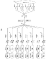
図1は、光アクセスネットワークシステム(以下、光アクセス網)の構成図である。光アクセス網は、4台のOLT10(10−A〜10−D)、光スプリッタ30、31、複数のONU20(20−A−1〜20−D−n4)、及び複数の端末50(50−A−1〜50−D−n4)を備える。OLT10は、局側装置であり、ONU20は加入者装置である。
(Optical access network)
FIG. 1 is a block diagram of an optical access network system (hereinafter referred to as an optical access network). The optical access network includes four OLTs 10 (10-A to 10-D), optical splitters 30, 31, a plurality of ONUs 20 (20-A-1 to 20-D-n4), and a plurality of terminals 50 (50- A-1 to 50-D-n4) are provided. The OLT 10 is a station-side device, and the ONU 20 is a subscriber device.

複数のOLT10は、ネットワーク60と接続する。ネットワーク60は、インターネットであってもよいし、LAN等のネットワークであってもよい。OLT10は、ネットワーク60から受信した信号を、ONU20に送信する。また、OLT10は、ONU20から受信した信号を、ネットワーク60に送信する。   The plurality of OLTs 10 are connected to the network 60. The network 60 may be the Internet or a network such as a LAN. The OLT 10 transmits a signal received from the network 60 to the ONU 20. Also, the OLT 10 transmits a signal received from the ONU 20 to the network 60.

複数のOLT10(10−1〜10−4)は、光スプリッタ30と接続する。光スプリッタ30は、幹線光ファイバ40−0を介して光スプリッタ31と接続する。光スプリッタ31は、支線の光ファイバ40(40−A−1〜40−D−n4)を介してONU20(20−A−1〜20−D−n4)と接続する。端末50(50−A−1〜50−D−n4)は、それぞれONU20(20−A−1〜20−D−n4)と接続する。   The plurality of OLTs 10 (10-1 to 10-4) are connected to the optical splitter 30. The optical splitter 30 is connected to the optical splitter 31 via the trunk optical fiber 40-0. The optical splitter 31 is connected to the ONUs 20 (20-A-1 to 20-D-n4) via the branch optical fibers 40 (40-A-1 to 40-D-n4). The terminals 50 (50-A-1 to 50-D-n4) are connected to the ONUs 20 (20-A-1 to 20-D-n4), respectively.

ONU20からOLT10への通信を上り通信、上り通信に用いる波長を上り波長と呼ぶ。逆に、OLT10からONU20への通信を下り通信、下り通信に用いる波長を下り波長と呼ぶ。   Communication from the ONU 20 to the OLT 10 is called upstream communication, and a wavelength used for upstream communication is called upstream wavelength. Conversely, communication from the OLT 10 to the ONU 20 is called downstream communication, and a wavelength used for downstream communication is called downstream wavelength.

複数のOLT10の信号の多重方法について説明する。ONU20−A−1〜20−A−n1は、下り波長λAd及び上り波長λAuを用いて、OLT10−1と通信する。ONU20−B−1〜20−B−n1は、下り波長λBd及び上り波長λBuを用いて、OLT10−2と通信する。ONU20−C−1〜20−C−n1は、下り波長λCd及び上り波長λCuを用いて、OLT10−3と通信する。ONU20−D−1〜20−D−n1は、下り波長λDd及び上り波長λDuを用いて、OLT10−4と通信する。光スプリッタ30は複数のOLT10から受信した信号を合波して幹線ファイバ40−0に出力する。また、光スプリッタ30は、幹線ファイバ40−0から入力された光信号を複数のOLT10に分波して出力する。光スプリッタ31も同様に分波、合波する。   A method of multiplexing signals of a plurality of OLTs 10 will be described. The ONUs 20 -A to 20 -A-n 1 communicate with the OLT 10-1 using the downstream wavelength λAd and the upstream wavelength λAu. The ONUs 20-B-1 to 20-B-n1 communicate with the OLT 10-2 using the downstream wavelength λBd and the upstream wavelength λBu. The ONUs 20-C-1 to 20-C-n 1 communicate with the OLT 10-3 using the downstream wavelength λCd and the upstream wavelength λCu. The ONUs 20 -D to 20 -D-n 1 communicate with the OLT 10-4 using the downstream wavelength λDd and the upstream wavelength λDu. The optical splitter 30 multiplexes the signals received from the plurality of OLTs 10 and outputs the multiplexed signal to the trunk fiber 40-0. Also, the optical splitter 30 splits the optical signal input from the trunk fiber 40-0 to a plurality of OLTs 10 and outputs the split optical signals. The optical splitter 31 also splits and combines in the same manner.

このように、本実施例の光アクセス網において、複数のOLT10は、異なる波長で波長多重してONU20と通信する。また、本実施例のOLT10は、下り波長と上り波長とが異なる波長を利用して、下り通信と上り通信とを多重する。   As described above, in the optical access network according to the present embodiment, a plurality of OLTs 10 communicate with the ONU 20 by wavelength multiplexing at different wavelengths. Furthermore, the OLT 10 according to the present embodiment multiplexes downstream communication and upstream communication using wavelengths different between the downstream wavelength and the upstream wavelength.

OLT10−ONU20間の下り通信に関して説明する。幹線光ファイバ40−0を通る光信号は、OLT10からONU20へ向けたすべての波長の光信号が多重されて含まれる。そのため、ONU20はそれらすべての波長の下り光信号を受信する。   The downstream communication between the OLT 10 and the ONU 20 will be described. The optical signals passing through the trunk optical fiber 40-0 include optical signals of all wavelengths directed from the OLT 10 to the ONU 20 in a multiplexed manner. Therefore, the ONU 20 receives downstream optical signals of all those wavelengths.

ONU20は、波長多重された下り光信号から自らが用いる波長を受信する。更に、ONU20は、OLT10から受信したフレーム内の識別子であるLLID(ロジカルリンクID)に基づいて、自ONU20宛てのフレームか否かを判定することによって、同じ波長の光信号によるフレームの中から自ONU20宛てのフレームを特定する。例えば、ONU20−A−1は、ONU20−A−1〜ONU20−A−n1宛てのフレームを含む光信号を受信する。そして、ONU20ーA−1は、LLIDに基づいてONU20−A−1宛てのフレームを、通信プロトコルの上位層の処理に転送し、それ以外のフレームは廃棄する。このようにして、OLT10と複数のONU20とが下り通信する。   The ONU 20 receives the wavelength used by itself from the wavelength-multiplexed downstream optical signal. Furthermore, the ONU 20 determines whether or not the frame is addressed to its own ONU 20 based on the LLID (logical link ID) which is an identifier in the frame received from the OLT 10, thereby making it possible to The frame addressed to the ONU 20 is identified. For example, the ONU 20-A-1 receives an optical signal including a frame addressed to the ONU 20-A-1 to the ONU 20-A-n1. Then, the ONU 20-A-1 transfers the frame addressed to the ONU 20-A-1 to the process of the upper layer of the communication protocol based on the LLID, and discards the other frames. In this manner, the OLT 10 and the plurality of ONUs 20 communicate downstream.

OLT10−ONU20間の上り通信に関して説明する。ONU20−A−1〜ONU20−A−n1の各々は、同じ上り波長λAuを用いて、OLT10から指示された期間に自らが生成したバースト光信号を送信する。   Uplink communication between the OLT 10 and the ONU 20 will be described. Each of the ONUs 20-A-1 to ONU 20-A-n1 transmits a burst optical signal generated by itself during a period instructed from the OLT 10 using the same upstream wavelength λAu.

このように各ONU20に指示された期間(ONU20毎に異なる期間)にバースト光信号を送信することによって、複数のONU20からの上り光信号が衝突するのを防ぐ。OLT10は、時分割で多重された複数のONU20からのバースト光信号を受信する。このようにして、OLT10と複数のONU20とが上り通信することができる。そして、複数のOLT10と複数のONU20とが同一の光ファイバ40を共有して通信することができる。   As described above, by transmitting the burst optical signals in a period instructed by each ONU 20 (a different period for each ONU 20), collision of upstream optical signals from a plurality of ONUs 20 is prevented. The OLT 10 receives burst optical signals from a plurality of ONUs 20 time-divisionally multiplexed. Thus, the OLT 10 and the plurality of ONUs 20 can perform upstream communication. Then, the plurality of OLTs 10 and the plurality of ONUs 20 can communicate by sharing the same optical fiber 40.

(OLT10の機能構成)
図2は、本実施例のOLT10の構成図である。OLT10は、光送受信器110、PON PHY/MAC(PON Physical/Media Access Control)処理部120、マルチプレクサ130、デマルチプレクサ140、MPCP(Multi−Point Control Protocol)処理部150、下りトラフィック処理部160、上りトラフィック処理部170、およびOLT制御部180を含む。ここでは、ONU20が、波長λAの光信号を送受信する場合について説明する。
(Functional configuration of OLT 10)
FIG. 2 is a block diagram of the OLT 10 of the present embodiment. The OLT 10 includes an optical transceiver 110, a PON PHY / MAC (PON Physical / Media Access Control) processing unit 120, a multiplexer 130, a demultiplexer 140, an MPCP (Multi-Point Control Protocol) processing unit 150, a downstream traffic processing unit 160, and upstream. A traffic processing unit 170 and an OLT control unit 180 are included. Here, the case where the ONU 20 transmits and receives an optical signal of the wavelength λA will be described.

光送受信器110は、電気信号と光信号を相互に変換する。光送受信器110は、光スプリッタ30から入力された上り波長λAuの上り光信号を受信し、受信した上り光信号を電流信号に変換する。さらに、光送受信器110は、変換後の電流信号を電圧信号に変換及び増幅し、アナログの電気信号をデジタル信号に変換して、PON PHY/MAC処理部120に出力する。   The optical transceiver 110 mutually converts an electrical signal and an optical signal. The optical transceiver 110 receives the upstream optical signal of the upstream wavelength λAu input from the optical splitter 30, and converts the received upstream optical signal into a current signal. Furthermore, the optical transceiver 110 converts and converts the converted current signal into a voltage signal, converts an analog electrical signal into a digital signal, and outputs the digital signal to the PON PHY / MAC processing unit 120.

また、光送受信器110は、PON PHY/MAC処理部120から入力された電気信号を下り波長λAdのOFDM(直交周波数分割多重:Orthogonal Frequency−Division Multiplexing)−PONにおける光信号に変換し、この変換によって生成された光信号を下り光信号として光スプリッタ30に出力する。これによって、光送受信器110は、下りトラフィックを下り波長λAdの下り光信号に変換し、下り光信号をONU20に送信する。   In addition, the optical transceiver 110 converts the electrical signal input from the PON PHY / MAC processing unit 120 into an optical signal in the OFDM (Orthogonal Frequency-Division Multiplexing) -PON of downstream wavelength λAd, and this conversion Is output to the optical splitter 30 as a downstream optical signal. Thus, the optical transmitter / receiver 110 converts downstream traffic into a downstream optical signal of downstream wavelength λAd, and transmits the downstream optical signal to the ONU 20.

光送受信器110は、OLT制御部180からの指示に従って、OFDM−PONにおける光信号のパラメータを、光送受信器110内の光送信部及び光受信部に設定する。これらのパラメータは、OLT制御部180において変更可能である。   The optical transmitter / receiver 110 sets parameters of the optical signal in the OFDM-PON in the optical transmitter and the optical receiver in the optical transmitter / receiver 110 according to the instruction from the OLT control unit 180. These parameters can be changed in the OLT control unit 180.

光信号のパラメータとは、波長、変調方式、シンボルレート、サブキャリア数、及び、サンプリングレート等である。光送受信器120は、これらのパラメータを変更することによって、下り光信号及び上り光信号の伝送容量を変更することができる。光送受信器110は、送信光信号の波長を調整可能なレーザーを用いる装置を光送信部として有することで、光送信部が送信する波長を変更できる。また、光送受信器110は、受信光信号の波長を調整可能な光フィルタを用いる装置を光受信部として有することで、光受信部が受信する波長を変更できる。   The parameters of the optical signal are wavelength, modulation scheme, symbol rate, number of subcarriers, sampling rate and the like. The optical transmitter / receiver 120 can change the transmission capacity of the downstream optical signal and the upstream optical signal by changing these parameters. The optical transmitter / receiver 110 can change the wavelength transmitted by the optical transmission unit by including an apparatus using a laser capable of adjusting the wavelength of the transmission optical signal as the optical transmission unit. In addition, the optical transmitter / receiver 110 can change the wavelength to be received by the optical receiving unit by including an apparatus using an optical filter capable of adjusting the wavelength of the received optical signal as the optical receiving unit.

(PON PHY/MAC処理部120)
PON PHY/MAC処理部120は、PON区間のPHY(Physical)層及びMAC(Media Access Control)層の処理を実行する処理部である。PON PHY/MAC処理部120は、マルチプレクサ処理部130から入力された下り方向のMACフレームに対して、MACフレームのプリアンブル部分に送信先に対応するLLIDを付与した後、FEC(Forward Error Correction)エンコード処理や64B66B等の符号化処理を実行する。更に、PON PHY/MAC処理部120は、符号化された信号をパラレル信号からシリアル信号に変換して、光送受信器110に出力する。
(PON PHY / MAC processor 120)
The PON PHY / MAC processing unit 120 is a processing unit that executes processing of a PHY (Physical Layer) and a MAC (Media Access Control) layer in the PON section. The PON PHY / MAC processing unit 120 adds an LLID corresponding to the transmission destination to the preamble portion of the MAC frame for the downlink MAC frame input from the multiplexer processing unit 130, and then performs FEC (Forward Error Correction) encoding. Execute processing and encoding processing such as 64B66B. Furthermore, the PON PHY / MAC processing unit 120 converts the encoded signal from a parallel signal into a serial signal and outputs the converted signal to the optical transceiver 110.

また、PON PHY/MAC処理部120は、光送受信器110からデジタル変換された上りの電気信号を受信し、シリアル信号としての電気信号をパラレル信号に変換して、FECデコード処理や64B66B等の復号化処理を実行する。更に、復号化により出力されたMACフレームのプリアンブル部分を解析し、LLIDを除去してデマルチプレクサ140に出力する。   Further, the PON PHY / MAC processing unit 120 receives the upstream electrical signal digitally converted from the optical transmitter / receiver 110, converts the electrical signal as a serial signal into a parallel signal, and decodes the FEC decoding processing, 64B66B, etc. Execute the conversion process. Furthermore, the preamble part of the MAC frame output by the decoding is analyzed, the LLID is removed, and the resultant is output to the demultiplexer 140.

(マルチプレクサ130)
マルチプレクサ130は、MPCP処理部150から入力されたMPCP制御フレームと下りトラフィック処理部160から入力された下りユーザーデータフレームを多重して、PON PHY/MAC処理部120に出力する。
(Multiplexer 130)
The multiplexer 130 multiplexes the MPCP control frame input from the MPCP processing unit 150 and the downstream user data frame input from the downstream traffic processing unit 160, and outputs the multiplexed data to the PON PHY / MAC processing unit 120.

(デマルチプレクサ140)
デマルチプレクサ140は、PON PHY/MAC処理部120からMACフレームを受信して、MACフレームのヘッダ情報を解析し、MPCP制御フレームと上りユーザーデータフレームを識別し、MPCP制御フレームをMPCP処理部150に出力し、上りユーザーデータフレームを上りトラフィック処理部170に出力する。
(Demultiplexer 140)
The demultiplexer 140 receives the MAC frame from the PON PHY / MAC processing unit 120, analyzes the header information of the MAC frame, identifies the MPCP control frame and the uplink user data frame, and transmits the MPCP control frame to the MPCP processing unit 150. The uplink user data frame is output to the uplink traffic processing unit 170.

(MPCP処理部150)
MPCP処理部150は、OLT10とONU20間でやりとりされるMPCP制御フレームの送信及び受信の処理をおこなう。MPCP処理部150では、ONU20に対して上り送信許可を与えるGATEフレーム、新規接続したONU20に対する送信許可を与えるDiscovery GATEフレーム、ONU20に対して登録を指示するREGISTERフレームを発行し、マルチプレクサに出力する。また、MPCP処理部150は、ONU20が上りデータ量を通知するREPORTフレーム、ONU20が登録要求を通知するREGISTER_REQフレームをデマルチプレクサ140から受信する。
(MPCP processing unit 150)
The MPCP processing unit 150 performs transmission and reception processing of an MPCP control frame exchanged between the OLT 10 and the ONU 20. The MPCP processing unit 150 issues a GATE frame for giving the upstream transmission permission to the ONU 20, a Discovery GATE frame for giving the transmission permission to the newly connected ONU 20, and a REGISTER frame instructing the ONU 20 to register, and outputs them to the multiplexer. Also, the MPCP processing unit 150 receives, from the demultiplexer 140, the REPORT frame in which the ONU 20 notifies the amount of upstream data, and the REGISTER_REQ frame in which the ONU 20 notifies the registration request.

(下りトラフィック処理部160)
下りトラフィック処理部160は、ネットワーク60からユーザーデータフレームを受信し、受信したユーザーデータフレームのヘッダ情報を解析し、ユーザーデータフレームを複数のキューに振分け、さらにそれら複数のキューからユーザーデータフレームを読み出し、マルチプレクサ130に出力する。
(Downlink traffic processing unit 160)
The downlink traffic processing unit 160 receives the user data frame from the network 60, analyzes the header information of the received user data frame, distributes the user data frame to a plurality of queues, and reads the user data frame from the plurality of queues. , Output to the multiplexer 130.

下りトラフィック処理部160は、スケジューラ1610、クラス毎キュー1620、フレーム振り分け処理部1630を含む。フレーム振り分け処理部1630は、ネットワーク60から受信した下りのユーザーデータフレームのヘッダ情報を解析し、ユーザーデータフレームの宛先のONU20の切替時間クラスを特定し、特定したクラスに基づいて、複数のクラス毎キュー1620に振分ける。ここでは、ユーザーデータフレームの送信先アドレスや付与されたVLANタグのVLAN−IDから宛先となるONU20を特定し、更に、宛先ONU20に対応する切替時間クラス(後述)を特定し、切替時間クラスに対応したクラス毎キュー1620に出力する。スケジューラ1610は、クラス毎キュー1620からユーザーデータフレームを読み出して、マルチプレクサ140に出力する。このスケジューラ1610は、OLT制御部180からの指示を受けて、キュー毎に読み出しの停止、読み出しの再開を実行する。この構成によれば、OLT制御部180が下り波長λAdの波長切替完了のタイミングに基づいて、下りトラフィック処理部160での各クラスのキューの読み出しを制御することが可能である。   The downlink traffic processing unit 160 includes a scheduler 1610, a per-class queue 1620, and a frame distribution processing unit 1630. The frame distribution processing unit 1630 analyzes the header information of the downstream user data frame received from the network 60, identifies the switching time class of the ONU 20 of the destination of the user data frame, and sets each of a plurality of classes based on the identified class. Allocate to queue 1620. Here, the ONU 20 to be the destination is specified from the transmission destination address of the user data frame and the VLAN-ID of the added VLAN tag, and further, the switching time class (described later) corresponding to the destination ONU 20 is specified. Output to the corresponding per-class queue 1620. The scheduler 1610 reads the user data frame from the per-class queue 1620 and outputs it to the multiplexer 140. In response to an instruction from the OLT control unit 180, the scheduler 1610 executes reading stop and restart reading for each queue. According to this configuration, it is possible for the OLT control unit 180 to control the reading of the queue of each class in the downstream traffic processing unit 160 based on the timing of wavelength switching completion of the downstream wavelength λAd.

(クラス毎キューの構成)
OLT10が備える複数のクラス毎キュー1620のサイズは、すべて同一でもよいし、クラスによって異なるサイズを用いてもよい。例えば、波長切替時間が長いクラスのキューのサイズを大きくし、波長切替時間が短いクラスのキューのサイズを小さくしてもよい。波長切替時間の長さに応じて各クラスのキューサイズを設定することでOLT10の備えるメモリ量を削減できる。
(Configuration of per-class queue)
The sizes of the plurality of per-class queues 1620 provided in the OLT 10 may be all the same, or different sizes may be used depending on the class. For example, the size of the class of the long wavelength switching time may be increased, and the size of the class of the short wavelength switching time may be reduced. The memory size of the OLT 10 can be reduced by setting the queue size of each class according to the length of the wavelength switching time.

(上りトラフィック処理部170)
上りトラフィック処理部170は、デマルチプレクサ140から上りのユーザーデータフレームを受信して、一旦バッファに蓄積して、必要があれば、優先度制御や帯域制御を実施してネットワーク60に出力する。
(Uplink traffic processing unit 170)
The uplink traffic processing unit 170 receives an uplink user data frame from the demultiplexer 140, temporarily stores it in a buffer, performs priority control and band control, if necessary, and outputs the result to the network 60.

(OLT制御部180)
OLT制御部180は、OLT10内の下りトラフィック処理部160、MPCP処理部150、光送受信器110の動作をモニタし、これらの処理部に対してパラメータの設定変更などを実行する。OLT制御部180は、光送受信器110に対して送信波長、受信波長の設定指示をおこなう。また、OLT制御部180は、下りトラフィック処理部160に対して、各クラスキューからのユーザーデータフレームの読みだしの停止、再開指示を出す。また、OLT制御部180は、MPCP処理部150に対して波長切替に関する制御フレーム送信の指示を出したり、MPCP処理部から波長切替制御フレームの受信イベントをモニタしたりする。OLT制御部180の動作の詳細については後述する。
(OLT control unit 180)
The OLT control unit 180 monitors the operations of the downstream traffic processing unit 160, the MPCP processing unit 150, and the optical transceiver 110 in the OLT 10, and performs parameter setting change and the like on these processing units. The OLT control unit 180 instructs the optical transceiver 110 to set the transmission wavelength and the reception wavelength. In addition, the OLT control unit 180 instructs the downstream traffic processing unit 160 to stop and resume reading of user data frames from each class queue. Further, the OLT control unit 180 instructs the MPCP processing unit 150 to transmit a control frame related to wavelength switching, and monitors an event for receiving a wavelength switching control frame from the MPCP processing unit. Details of the operation of the OLT control unit 180 will be described later.

本実施例のOLT10の構成によれば、OLT10は、波長切替の制御と連携して下りトラフィックの制御が可能であり、また、切替時間のクラス毎にトラフィックを制御することが可能である。
(OLTのハードウェア構成)
図3は、OLT10のハードウェア構成図である。OLT10は、光送受信器110、PON論理回路190、CPU191、およびメモリ192を有する。各部はバスを介して相互に接続されており、相互に制御用のデータをやりとりすることが可能である。OLT10の機能構成で述べた、PON PHY/MAC処理部120、マルチプレクサ130、デマルチプレクサ140、MPCP処理部150、下りトラフィック処理部160、および上りトラフィック処理部170は、ASIC(Application Specific Integrated Circuit)やFPGA(Field Programmable Gate Array)などの論理回路で実現され、OLT制御部180は、CPU191とメモリ192により実現される。
According to the configuration of the OLT 10 of this embodiment, the OLT 10 can control downlink traffic in cooperation with wavelength switching control, and can control traffic for each switching time class.
(Hardware configuration of OLT)
FIG. 3 is a hardware configuration diagram of the OLT 10. The OLT 10 includes an optical transceiver 110, a PON logic circuit 190, a CPU 191, and a memory 192. The respective units are mutually connected via a bus, and can exchange control data with each other. The PON PHY / MAC processing unit 120, the multiplexer 130, the demultiplexer 140, the MPCP processing unit 150, the downstream traffic processing unit 160, and the upstream traffic processing unit 170 described in the functional configuration of the OLT 10 are ASIC (Application Specific Integrated Circuit) The OLT control unit 180 is realized by the CPU 191 and the memory 192, and is realized by a logic circuit such as an FPGA (Field Programmable Gate Array).

(ONU20)
図4は、本実施例のONU20の構成図である。ONU20は、光送受信器210、PON PHY/MAC処理部220、マルチプレクサ230、デマルチプレクサ240、MPCP処理部250、上りトラフィック処理部260、下りトラフィック処理部270、およびONU制御部280を含む。ここでは、ONU20が、波長λAの光信号を送受信する場合について説明する。
(ONU 20)
FIG. 4 is a block diagram of the ONU 20 of this embodiment. The ONU 20 includes an optical transceiver 210, a PON PHY / MAC processor 220, a multiplexer 230, a demultiplexer 240, an MPCP processor 250, an upstream traffic processor 260, a downstream traffic processor 270, and an ONU controller 280. Here, the case where the ONU 20 transmits and receives an optical signal of the wavelength λA will be described.

光送受信器210は、電気信号と光信号を相互に変換する。光送受信器210は、光スプリッタ31から入力された下り波長λAdの下り光信号を受信し、受信した下り光信号を電流信号に変換する。さらに、光送受信器210は、変換後の電流信号を電圧信号に変換及び増幅し、アナログの電気信号をデジタル信号に変換して、PON PHY/MAC処理部220に出力する。   The optical transceiver 210 mutually converts an electrical signal and an optical signal. The optical transmitter / receiver 210 receives the downstream optical signal of the downstream wavelength λAd input from the optical splitter 31, and converts the received downstream optical signal into a current signal. Furthermore, the optical transceiver 210 converts and converts the converted current signal into a voltage signal, converts an analog electrical signal into a digital signal, and outputs the digital signal to the PON PHY / MAC processing unit 220.

また、光送受信器210は、PON PHY/MAC処理部220から入力された電気信号を上り波長λAuのOFDM(直交周波数分割多重:orthogonal frequency−division multiplexing)−PONにおける光信号に変換し、この変換によって生成された光信号を上り光信号として光スプリッタ31に出力する。これによって、光送受信器210は、上りトラフィックを上り波長λAuの上り光信号に変換し、上り光信号をOLT10に送信する。   In addition, the optical transmitter / receiver 210 converts the electrical signal input from the PON PHY / MAC processing unit 220 into an optical signal in the OFDM (orthogonal frequency-division multiplexing) -PON of the upstream wavelength λAu, and this conversion Is output to the optical splitter 31 as an upstream optical signal. Thus, the optical transmitter / receiver 210 converts the upstream traffic into an upstream optical signal of the upstream wavelength λAu, and transmits the upstream optical signal to the OLT 10.

光送受信器210は、ONU制御部280からの指示に従って、OFDM−PONにおける光信号のパラメータを光送受信器210内の光送信部及び光受信部に設定する。これらのパラメータは、OLT制御部180からの指示に基づいてONU制御部280において変更可能である。   The optical transmitter-receiver 210 sets parameters of the optical signal in the OFDM-PON in the optical transmitter and the optical receiver in the optical transmitter-receiver 210 according to the instruction from the ONU controller 280. These parameters can be changed in the ONU control unit 280 based on an instruction from the OLT control unit 180.

光信号のパラメータとは、波長、変調方式、シンボルレート、サブキャリア数、及び、サンプリングレート等である。光送受信器210は、送信光信号の波長を調整可能なレーザーを用いる装置を光送信部として有することで、光送信部が送信する波長を変更できる。また、光送受信器210は、受信光信号の波長を調整可能な光フィルタを用いる装置を光受信部として有することで、光受信部が受信する波長を変更できる。   The parameters of the optical signal are wavelength, modulation scheme, symbol rate, number of subcarriers, sampling rate and the like. The optical transmitter / receiver 210 can change the wavelength to be transmitted by the optical transmission unit by including an apparatus using a laser capable of adjusting the wavelength of the transmission optical signal as the optical transmission unit. Further, the optical transmitter / receiver 210 can change the wavelength to be received by the optical receiver by including an apparatus using an optical filter capable of adjusting the wavelength of the received optical signal as the optical receiver.

(PON PHY/MAC処理部220)
PON PHY/MAC処理部220は、PON区間のPHY層及びMAC層の処理を実行する処理部である。PON PHY/MAC処理部220は、マルチプレクサ処理部230から入力された上り方向のMACフレームに対して、MACフレームのプリアンブル部分に送信先に対応するLLIDを付与した後、FECエンコード処理や64B66B等の符号化処理を実行する。更に、PON PHY/MAC処理部220は、符号化された信号をパラレル信号からシリアル信号に変換して、光送受信器210に出力する。
(PON PHY / MAC processor 220)
The PON PHY / MAC processing unit 220 is a processing unit that executes processing of the PHY layer and the MAC layer of the PON section. The PON PHY / MAC processing unit 220 adds LLID corresponding to the transmission destination to the preamble part of the MAC frame for the upstream MAC frame input from the multiplexer processing unit 230, and then performs FEC encoding processing, 64B66B, etc. Execute encoding processing. Furthermore, the PON PHY / MAC processing unit 220 converts the encoded signal from a parallel signal into a serial signal and outputs the converted signal to the optical transceiver 210.

また、PON PHY/MAC処理部220は、光送受信器210からデジタル変換された下りの電気信号を受信し、シリアル信号としての電気信号をパラレル信号に変換して、FECデコード処理や64B66B等の復号化処理を実行する。更に、復号化により出力されたMACフレームのプリアンブル部分を解析し、LLIDを除去してデマルチプレクサ240に出力する。   Also, the PON PHY / MAC processing unit 220 receives the downstream electrical signal digitally converted from the optical transmitter / receiver 210, converts the electrical signal as a serial signal into a parallel signal, and decodes the FEC decoding processing, 64B66B, etc. Execute the conversion process. Furthermore, the preamble part of the MAC frame output by the decoding is analyzed, the LLID is removed, and the resultant is output to the demultiplexer 240.

(マルチプレクサ230)
マルチプレクサ230は、MPCP処理部250から入力されたMPCP制御フレームと上りトラフィック処理部260から入力された上りユーザーデータフレームを多重して、PON PHY/MAC処理部220に出力する。
(Multiplexer 230)
The multiplexer 230 multiplexes the MPCP control frame input from the MPCP processing unit 250 and the upstream user data frame input from the upstream traffic processing unit 260, and outputs the multiplexed data to the PON PHY / MAC processing unit 220.

(デマルチプレクサ240)
デマルチプレクサ240は、PON PHY/MAC処理部220からMACフレームを受信して、MACフレームのヘッダ情報を解析し、MPCP制御フレームと下りユーザーデータフレームを識別し、MPCP制御フレームをMPCP処理部250に出力し、下りユーザーデータフレームを下りトラフィック処理部270に出力する。
(Demultiplexer 240)
The demultiplexer 240 receives the MAC frame from the PON PHY / MAC processor 220, analyzes the header information of the MAC frame, identifies the MPCP control frame and the downstream user data frame, and transmits the MPCP control frame to the MPCP processor 250. The downlink user data frame is output to the downlink traffic processing unit 270.

(MPCP処理部250)
MPCP処理部250は、OLT10とONU20間でやりとりされるMPCP制御フレームの送信及び受信の処理をおこなう。MPCP処理部250では、ONU20が上りデータ量を通知するREPORTフレーム、ONU20が登録要求を通知するREGISTER_REQフレームを発行し、マルチプレクサ230に出力する。また、MPCP処理部250は、ONU20に対して上り送信許可を与えるGATEフレーム、新規接続したONU20に対する送信許可を与えるDiscovery GATEフレーム、ONU20に対して登録を指示するREGISTERフレームをデマルチプレクサ240から受信する。
(MPCP processing unit 250)
The MPCP processing unit 250 performs transmission and reception processing of an MPCP control frame exchanged between the OLT 10 and the ONU 20. The MPCP processing unit 250 issues a REPORT frame in which the ONU 20 notifies the amount of upstream data, and a REGISTER_REQ frame in which the ONU 20 notifies a registration request, and outputs the frame to the multiplexer 230. Also, the MPCP processing unit 250 receives from the demultiplexer 240 a GATE frame for giving the upstream transmission permission to the ONU 20, a Discovery GATE frame for giving the transmission permission to the newly connected ONU 20, and a REGISTER frame instructing the ONU 20 to register. .

(上りトラフィック処理部260)
上りトラフィック処理部260は、端末50からユーザーデータフレームを受信し、一旦バッファに蓄積して、必要があれば、優先度制御等を実施し、マルチプレクサ230に出力する。
(Uplink traffic processing unit 260)
The uplink traffic processing unit 260 receives a user data frame from the terminal 50, temporarily stores it in a buffer, implements priority control and the like if necessary, and outputs the result to the multiplexer 230.

(下りトラフィック処理部270)
下りトラフィック処理部270は、デマルチプレクサ240から下りユーザーデータフレームを受信して、一旦バッファに蓄積して、優先度制御や帯域制御を実施して端末50に出力する。
(Downlink traffic processing unit 270)
The downlink traffic processing unit 270 receives the downlink user data frame from the demultiplexer 240, temporarily stores it in the buffer, implements priority control and band control, and outputs the result to the terminal 50.

(ONU制御部280)
ONU制御部280は、ONU20内の上りトラフィック処理部260、MPCP処理部250、光送受信器210の動作をモニタし、これらの処理部に対してパラメータの設定変更などを実行する。ONU制御部280は、光送受信器210に対して送信波長、受信波長の設定指示をおこなう。また、ONU制御部280は、MPCP処理部250に対して波長切替に関する制御フレーム送信の指示を出したり、MPCP処理部250から波長切替制御フレームの受信イベントをモニタしたりする。
(ONU controller 280)
The ONU control unit 280 monitors the operations of the upstream traffic processing unit 260, the MPCP processing unit 250, and the optical transceiver 210 in the ONU 20, and executes parameter setting change and the like for these processing units. The ONU control unit 280 instructs the optical transceiver 210 to set the transmission wavelength and the reception wavelength. Further, the ONU control unit 280 instructs the MPCP processing unit 250 to transmit a control frame related to wavelength switching, and monitors the reception event of the wavelength switching control frame from the MPCP processing unit 250.

本実施例のONU20の構成によれば、ONU20は、OLT10からの波長切替を指示する制御フレームを受信して、ONU20が備える光送受信器210の波長を変更し、変更後の波長にて制御フレームをOLT10に送信することが可能である。   According to the configuration of the ONU 20 of the present embodiment, the ONU 20 receives a control frame instructing wavelength switching from the OLT 10, changes the wavelength of the optical transceiver 210 provided in the ONU 20, and controls the control frame using the changed wavelength. Can be sent to the OLT 10.

(OLT制御部180の処理)
図5は、本実施例のOLT制御部180の処理フローチャートである。
(Processing of the OLT control unit 180)
FIG. 5 is a process flowchart of the OLT control unit 180 according to this embodiment.

OLT制御部180は、波長切替のトリガーの検出に応答して、処理の実行を開始する(S101)。波長切替のトリガーは、OLT10に直接またはネットワーク(ネットワーク60又は他のネットワーク)を介して接続されたオペレーション端末(図示略)からの指示、及び/又はOLT10内でのトラフィック量の変化の検出である。   In response to the detection of the trigger for wavelength switching, the OLT control unit 180 starts the execution of the process (S101). The trigger for wavelength switching is an instruction from an operation terminal (not shown) connected to OLT 10 directly or via a network (network 60 or another network), and / or detection of a change in traffic volume in OLT 10 .

OLT制御部180は、OLT10に登録されているすべてのONU20(以下、すべてのONU20とは、OLT10に登録されている切替対象のすべてのONU20の意味である。)に対して、波長切替要求を表す制御フレームをMPCP処理部150を介して送信する(S102)。なお、波長切替要求を表す制御フレームの送信と共に、上りの送信許可を表すGATEフレームを送信してもよい。GATEフレームを送信することで、ONU20が波長切替要求に対する応答を迅速に送信することが可能となる。   The OLT control unit 180 sends a wavelength switching request to all ONUs 20 registered in the OLT 10 (hereinafter, all ONUs 20 mean all ONUs 20 to be switched registered in the OLT 10). The control frame to be represented is transmitted via the MPCP processing unit 150 (S102). Note that, along with the transmission of the control frame representing the wavelength switching request, the GATE frame representing the uplink transmission permission may be transmitted. By transmitting the GATE frame, the ONU 20 can quickly transmit a response to the wavelength switching request.

OLT制御部180は、波長切替要求を送信したONU20から波長切替要求応答の受信を待つ(S103)。予め設定した時間(タイムアウト時間)内にすべてのONU20から波長切替要求応答を受信した場合には、S104に移る。タイムアウト時間内にすべてのONU20から波長切替要求応答を受信できなかった場合には、OLT制御部180はS118に移る。OLT制御部180は、波長切替要求応答を受信できなかった旨を表す警報メッセージを発行する(S118)。この警報メッセージは、OLT10と接続されたオペレーション端末に送信され、そのオペレーション端末にて表示される。   The OLT control unit 180 waits for reception of a wavelength switching request response from the ONU 20 that has transmitted the wavelength switching request (S103). If the wavelength switching request responses have been received from all the ONUs 20 within a preset time (timeout time), the process proceeds to S104. When the wavelength switching request response can not be received from all the ONUs 20 within the timeout time, the OLT control unit 180 proceeds to S118. The OLT control unit 180 issues an alarm message indicating that the wavelength switching request response could not be received (S118). This alarm message is transmitted to the operation terminal connected to the OLT 10 and displayed on the operation terminal.

OLT制御部180は、波長切替要求を送信したONU20から受信した波長切替要求応答のメッセージを解析し、メッセージ内のACK/NACKを確認する(S104)。OLT制御部180は、すべてのONU20からのメッセージにおいてACKを確認した場合にはS105に移り、少なくとも1台のONU20からのメッセージにおいてNACKを確認した場合には、OLT10は波長切替の処理を中断し、S117に移る。OLT制御部180は、ONUから切替拒否があった旨を表すイベント発生メッセージを発行する(S117)。このメッセージは、例えば、OLT10と接続されたオペレーション端末に送信され、そのオペレーション端末にて表示される。   The OLT control unit 180 analyzes the message of the wavelength switching request response received from the ONU 20 that has transmitted the wavelength switching request, and confirms ACK / NACK in the message (S104). If the OLT control unit 180 confirms ACK in messages from all ONUs 20, it moves to S105, and if NACK is confirmed in messages from at least one ONU 20, the OLT 10 interrupts the processing of wavelength switching , S117. The OLT control unit 180 issues an event occurrence message indicating that switching has been rejected from the ONU (S117). This message is transmitted, for example, to the operation terminal connected to the OLT 10 and displayed on the operation terminal.

OLT制御部180は、波長切替対象の全ONU20に波長切替指示メッセージを送信する(S105)。波長切替指示メッセージは、変更後の送信波長や受信波長の情報、および波長切替時刻を含む。波長切替指示メッセージはONU20毎にユニキャストで送信してもよいし、ブロードキャストにて全ONUに送信してもよい。   The OLT control unit 180 transmits a wavelength switching instruction message to all ONUs 20 targeted for wavelength switching (S105). The wavelength switching instruction message includes information on the changed transmission wavelength and reception wavelength, and wavelength switching time. The wavelength switching instruction message may be transmitted by unicast for each ONU 20 or may be transmitted to all ONUs by broadcast.

OLT制御部180は、下りトラフィック処理部160のスケジューラ1610を制御してクラス毎キュー1620からの下りユーザーデータフレームの読み出しを停止する(S106)。その結果、下りトラフィック処理部160は下りユーザーデータフレームの出力を停止し、下りユーザーデータフレームをクラス毎キュー1620に蓄積する。   The OLT control unit 180 controls the scheduler 1610 of the downlink traffic processing unit 160 to stop the reading of the downlink user data frame from the per-class queue 1620 (S106). As a result, the downlink traffic processing unit 160 stops the output of the downlink user data frame, and stores the downlink user data frame in the per-class queue 1620.

OLT制御部180は、OLT10内の光送受信器110に波長切替の指示を出す(S107)。波長切替の指示には、変更後の送信波長や受信波長の情報、および波長切替時刻が含まれる。波長切替の指示を受信した光送受信器110は、指示に従い送信波長や受信波長を変更する。   The OLT control unit 180 instructs the optical transmitter / receiver 110 in the OLT 10 to switch the wavelength (S107). The wavelength switching instruction includes information on the changed transmission wavelength and reception wavelength, and the wavelength switching time. The optical transceiver 110 that has received the wavelength switching instruction changes the transmission wavelength and the reception wavelength according to the instruction.

OLT制御部180は、波長切替対象のONU20からの切替完了通知の受信を所定時間待ち、所定時間内に切替完了通知を受信するか否かを判定する(S108)。OLT制御部180は、波長切替対象のONU20から切替完了通知を受信した場合にはS109に移り、所定時間内に切替完了通知を受信しなかった場合にはS114に移る。OLT制御部180は、ONU20に波長切替指示を送信した時刻からの経過時間を計測し、経過時間と予め設定した閾値との大小を判定する(S114)。閾値は、波長切替対象のONU20のすべてから切替完了通知の受信を確認するためのタイムアウト時間であり、個々のONU20に対するタイムアウト時間ではない。OLT制御部180は、経過時間≦閾値である場合にS108に戻り、経過時間>閾値である場合に、S115に移る。OLT制御部180は、ONU切替時間クラス管理テーブル(後述)でステータスが切替中のONU20を登録解除状態に強制的に遷移させ(S115)、S116に移る。OLT制御部180は、切替処理タイムアウトが発生したことを表すアラームを発行し(S116)、処理を終了する。このアラームは、OLT10と接続されたオペレーション端末に送信され、そのオペレーション端末にて表示される。   The OLT control unit 180 waits for reception of the notification of switching completion from the wavelength switching target ONU 20 for a predetermined time, and determines whether or not to receive the notification of switching completion within the predetermined time (S108). When the OLT control unit 180 receives the switching completion notification from the wavelength switching target ONU 20, it moves to S109, and when it does not receive the switching completion notification within the predetermined time, it moves to S114. The OLT control unit 180 measures the elapsed time from the time of transmitting the wavelength switching instruction to the ONU 20, and determines the magnitude of the elapsed time and the preset threshold (S114). The threshold is a timeout time for confirming reception of the switching completion notification from all of the wavelength switching target ONUs 20, and is not a timeout time for each ONU 20. The OLT control unit 180 returns to S108 if elapsed time ≦ threshold and proceeds to S115 if elapsed time> threshold. The OLT control unit 180 forcibly shifts the ONU 20 whose status is switched in the ONU switching time class management table (described later) to the deregistration state (S115), and proceeds to S116. The OLT control unit 180 issues an alarm indicating that the switching processing timeout has occurred (S116), and ends the processing. This alarm is transmitted to the operation terminal connected to the OLT 10 and displayed on the operation terminal.

OLT制御部180は、切替完了通知を受信したONU20の、切替完了通知に含まれるONU−IDを特定し、ONU切替時間クラス管理テーブルで該当するONU−IDのステータスを切替完了に変更する(S109)。   The OLT control unit 180 identifies the ONU-ID included in the switching completion notification of the ONU 20 that has received the switching completion notification, and changes the status of the corresponding ONU-ID in the ONU switching time class management table to switching completion (S109) ).

OLT制御部180は、ONU切替時間クラス管理テーブルを参照して、特定したONU−IDのONU20が属するクラス(#x)を特定する(S110)。   The OLT control unit 180 identifies the class (#x) to which the ONU 20 of the identified ONU-ID belongs, with reference to the ONU switching time class management table (S110).

OLT制御部180は、特定したクラス#xに所属するすべてのONU20のステータスをONU切替時間クラス管理テーブルから取得し、該当するすべてのONU20のステータスが切替完了になっているか否かを判定する(S111)。OLT制御部180は、切替完了である場合にS112に移り、切替完了でない場合にS108に戻る。   The OLT control unit 180 acquires the status of all ONUs 20 belonging to the identified class #x from the ONU switching time class management table, and determines whether the status of all the corresponding ONUs 20 is switching completed S111). The OLT control unit 180 moves to S112 when the switching is completed, and returns to S108 when the switching is not completed.

OLT制御部180は、特定したクラス#xに対応するキューからの読み出し再開を下りトラフィック処理部160に指示する(S112)。指示を受けた下りトラフィック処理部160は、スケジューラ1610を制御してクラス#xに対応するキューからのユーザーデータフレームの読み出しを再開し、クラス#xに蓄積していたユーザーデータフレームが光送受信器110を介して送信される。   The OLT control unit 180 instructs the downstream traffic processing unit 160 to resume reading from the queue corresponding to the identified class #x (S112). Upon receiving the instruction, the downlink traffic processing unit 160 controls the scheduler 1610 to resume reading of the user data frame from the queue corresponding to class #x, and the user data frame stored in class #x is an optical transceiver It is sent via 110.

OLT制御部180は、ONU切替時間クラス管理テーブルを参照して登録されているONU20のステータスを確認し、すべてのONU20のステータスが切替完了となっているか否かを判定する(S113)。OLT制御部180は、切替完了である場合には処理を終了し、切替完了でない場合にはS108に戻る。   The OLT control unit 180 checks the status of the registered ONU 20 with reference to the ONU switching time class management table, and determines whether the status of all the ONUs 20 has been switched (S113). The OLT control unit 180 ends the processing when the switching is completed, and returns to S108 when the switching is not completed.

以上で述べたように、OLT制御部180は、切替時間クラス毎に蓄積されたトラフィックの送信再開処理を実行できる。   As described above, the OLT control unit 180 can execute transmission restart processing of traffic accumulated for each switching time class.

(ONU切替時間クラス管理テーブル)
図6は、OLT制御部180が備える、ONU切替時間クラス管理テーブルの例である。ONU切替時間クラス管理テーブルは、ONU20の識別子を表すONU−ID、ONUの切替状態を表すステータス、ONUの光送受信器の波長調整に要する波長調整時間、ONU−OLT間のラウンドトリップタイム、およびONUが所属するクラス番号を有する。ONU切替時間クラス管理テーブルは、新規にONU20が登録されるとエントリが追加される。波長調整時間やラウンドトリップの値は、ONU20の初期登録時にONU20からOLT10に通知され、OLT10は通知された値をONU切替時間クラス管理テーブルに追加する。
(ONU switching time class management table)
FIG. 6 is an example of an ONU switching time class management table provided in the OLT control unit 180. The ONU switching time class management table includes an ONU-ID representing an identifier of the ONU 20, a status representing the switching state of the ONU, a wavelength adjustment time required for wavelength adjustment of the optical transceiver of the ONU, round trip time between the ONU and the OLT, and ONU Has the class number to which it belongs. In the ONU switching time class management table, an entry is added when an ONU 20 is newly registered. The values of the wavelength adjustment time and the round trip are notified from the ONU 20 to the OLT 10 at the time of initial registration of the ONU 20, and the OLT 10 adds the notified value to the ONU switching time class management table.

ONU−IDは、OLT10に接続されたONU20を識別できるのであれば、どのような値でも構わない。例えば、ONU20に割り当てているVLAN IDを用いても、ONU20のシリアル番号(固有の装置番号)を用いても構わない。   The ONU-ID may have any value as long as the ONU 20 connected to the OLT 10 can be identified. For example, the VLAN ID assigned to the ONU 20 may be used, or the serial number (unique device number) of the ONU 20 may be used.

ステータスは、ONU20の切替状態を表し、「登録(切替完了)」、「切替中」、または「登録解除状態」を表す値が入力される。   The status indicates the switching state of the ONU 20, and a value indicating “registration (switching completed)”, “switching”, or “deregistration state” is input.

クラス番号は、各クラスでの切替時間範囲を予め設定しておき、ONU20の波長調整時間とラウンドトリップタイムから切替時間を算出し、算出した切替時間を含む切替時間範囲に対応するクラスを表す番号である。   The class number is a number representing a class corresponding to the switching time range including the switching time calculated from the wavelength adjustment time of the ONU 20 and the round trip time, with the switching time range in each class set in advance. It is.

(ONU波長調整時間収集シーケンス)
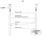
図7は、OLT10がONU20の波長調整時間を収集するシーケンス図である。OLT10はONU20に対して、制御フレームの一種であるDiscovery GATEフレームを送信する。この制御フレームは、OLT10に接続するすべてのONU20にブロードキャストされる。
(ONU wavelength adjustment time collection sequence)
FIG. 7 is a sequence diagram in which the OLT 10 collects the wavelength adjustment time of the ONU 20. The OLT 10 transmits, to the ONU 20, a Discovery GATE frame which is a type of control frame. This control frame is broadcast to all ONUs 20 connected to the OLT 10.

ONU20は、Discovery GATEフレームを受信すると、既にOLT10に登録済みの場合はこの制御フレームに応答せず、未登録の場合にこの制御フレームに応答する。図7の例では、ONU20は起動直後であり、OLT10に未登録であるので応答する。ONU20は、Discovery GATEフレームへの応答フレームであるREGISTER_REQフレームを送信する。この応答フレームを送信する際に、ONU20はONU20内の光送受信器210の波長調整時間を波長調整時間を応答フレーム内の所定のフィールドに格納して送信する。ONU20は、ONU20の光送受信器210の、下り受信部の波長調整時間DS_Tuning_Time及び上り送信部の波長調整時間US_Tuning _Timeを応答フレーム内の所定のフィールドに格納して送信する。   When receiving the Discovery GATE frame, the ONU 20 does not respond to this control frame if it is already registered in the OLT 10, but responds to this control frame if it is not registered. In the example of FIG. 7, the ONU 20 responds immediately because it has just been started and is not registered in the OLT 10. The ONU 20 transmits a REGISTER_REQ frame which is a response frame to the Discovery GATE frame. When transmitting this response frame, the ONU 20 stores the wavelength adjustment time of the optical transceiver 210 in the ONU 20 in the predetermined field in the response frame and transmits it. The ONU 20 stores the wavelength adjustment time DS_Tuning_Time of the downlink reception unit and the wavelength adjustment time US_Tuning_Time of the uplink transmission unit of the optical transceiver 210 of the ONU 20 in a predetermined field in the response frame and transmits the same.

OLT10は、REGISTER_REQフレームを受信した登録対象のONU20に対して制御フレームの一種である、REGISTERフレーム及びGATEフレームを送信する。ONU20はREGISTERフレームを受信すると、応答としてREGISTER_ACKを発行し、受信したGATEフレームで指定された送信許可期間内にREGISTER_ACKをOLT10に送信する。OLT10はREGISTER_ACKを受信すると、ONU切替時間クラス管理テーブルにエントリを追加し、ONU−IDに対応付けて波長調整時間を設定する。設定する波長調整時間は、上り及び下りの波長調整時間である。   The OLT 10 transmits a REGISTER frame and a GATE frame, which are a type of control frame, to the ONU 20 to be registered that has received the REGISTER_REQ frame. When the ONU 20 receives the REGISTER frame, the ONU 20 issues REGISTER_ACK as a response, and transmits REGISTER_ACK to the OLT 10 within the transmission permission period designated by the received GATE frame. When receiving the REGISTER_ACK, the OLT 10 adds an entry to the ONU switching time class management table, and sets the wavelength adjustment time in association with the ONU-ID. The wavelength adjustment time to be set is uplink and downlink wavelength adjustment times.

以上のONU波長調整時間収集シーケンスにより、OLT10はONU20を登録する際に、ONU20の波長調整時間を収集でき、収集したONU20の波長調整時間をONU−IDに対応付けたONU切替時間クラス管理テーブルを構築することができる。   With the above ONU wavelength adjustment time collection sequence, when the OLT 10 registers the ONU 20, the wavelength adjustment time of the ONU 20 can be collected, and the ONU switching time class management table in which the collected wavelength adjustment time of the ONU 20 is associated with the ONU-ID It can be built.

(波長切替シーケンス)
図8は、本実施例による波長切替シーケンス図である。ここでは、説明を分かり易くするために、切替要求や切替指示においてアラームが発生する事象が発生しないとする。また、ONU1、ONU2、ONU3、ONU4の順で波長切替時間が大きくなるとし、ONU1、ONU2はクラス1、ONU3、ONU4はクラス2に属するとする。
(Wavelength switching sequence)
FIG. 8 is a wavelength switching sequence diagram according to this embodiment. Here, in order to make the description easy to understand, it is assumed that an event that generates an alarm does not occur in the switching request or the switching instruction. Also, it is assumed that the wavelength switching time increases in the order of ONU1, ONU2, ONU3, ONU4, and that ONU1, ONU2 belong to class 1, ONU3, and ONU4 belong to class 2.

OLT10は、ONU20の登録時に、前述のONU波長調整時間収集シーケンスにより、ONU20の光送受信器210の波長調整時間を収集する。波長調整時間とラウンドトリップタイムから、波長切替時間を算出しておく。   The OLT 10 collects the wavelength adjustment time of the optical transceiver 210 of the ONU 20 according to the above-mentioned ONU wavelength adjustment time collection sequence when registering the ONU 20. The wavelength switching time is calculated from the wavelength adjustment time and the round trip time.

オペレーション端末(図中、OpS)などから、OLT10及びそのOLT10に接続するONU20が用いる波長を変更する指示を受けると、OLT制御部180は前述の処理(図5)を実行する。   When an instruction to change the wavelength used by the OLT 10 and the ONU 20 connected to the OLT 10 is received from the operation terminal (Ops in the figure) or the like, the OLT control unit 180 executes the above-described process (FIG. 5).

OLT10は切替対象のすべてのONU20に対して、波長切替要求メッセージを含む制御フレームと上り送信許可を表すGATEフレームを送信する。その後、OLT10はONU20からの波長切替要求応答を受信する。ここでは、波長切替要求応答はACK応答とする。   The OLT 10 transmits a control frame including a wavelength switching request message and a GATE frame indicating uplink transmission permission to all ONUs 20 to be switched. Thereafter, the OLT 10 receives the wavelength switching request response from the ONU 20. Here, the wavelength switching request response is an ACK response.

OLT10は切替対象のすべてのONU20に対して、波長切替指示メッセージを送信する。ここでは、ブロードキャストで送信する。   The OLT 10 transmits a wavelength switching instruction message to all ONUs 20 to be switched. Here, it transmits by broadcast.

OLT10は、スケジューラ1610を制御してクラス毎のキュー1620からのユーザーデータフレームの読み出しを停止し、OLT10からのユーザーデータフレームの送信を停止する。その後、OLT10の光送受信器110の波長の切替を実行する。また、OLT10は、波長の切替中にネットワーク60から受信したトラフィック(ユーザーデータフレーム)をクラス毎キュー1620に蓄積する。   The OLT 10 controls the scheduler 1610 to stop reading of user data frames from the per-class queue 1620, and stops transmission of user data frames from the OLT 10. After that, switching of the wavelength of the optical transmitter / receiver 110 of the OLT 10 is performed. Also, the OLT 10 stores traffic (user data frame) received from the network 60 during wavelength switching in the per-class queue 1620.

ONU20はOLT10から波長切替指示メッセージを受信し、受信したメッセージで指定された波長切替時刻に波長切替を実行する。ONU1〜ONU4は、それぞれの波長調整時間経過後に波長切替が完了する。   The ONU 20 receives the wavelength switching instruction message from the OLT 10, and executes wavelength switching at the wavelength switching time designated by the received message. The ONU 1 to ONU 4 complete the wavelength switching after the elapse of their respective wavelength adjustment times.

OLT10は、波長切替を実行したONU20に対して上り送信許可を表すGATEフレームを送信する。GATEフレームの送信は、OLT10の光送受信器の波長切替完了後に定期的に送信してもよいし、ONU20の波長調整時間に基づいて、波長切替完了後にGATEフレームを送信してもよい。   The OLT 10 transmits a GATE frame representing uplink transmission permission to the ONU 20 that has performed the wavelength switching. The transmission of the GATE frame may be periodically transmitted after the wavelength switching of the optical transmitter-receiver of the OLT 10 is completed, or the GATE frame may be transmitted after the wavelength switching is completed based on the wavelength adjustment time of the ONU 20.

ONU20は波長切替完了後にGATEフレームを受信すると、送信許可期間にOLT10宛てに切替完了通知メッセージを送信する。ここでは、ONU1、ONU2,ONU3、ONU4の順に波長切替が完了するため、切替完了通知メッセージもONU1、ONU2、ONU3,ONU4の順に送信される。OLT10は、ONU1及びONU2から波長切替完了通知メッセージを受信すると、クラス1に属するONU20(ONU1及びONU2)のすべてで波長切替が完了しているので、スケジューラ1610を制御してクラス1用キューからのユーザーデータフレームの読み出しを再開する。クラス1用キューから読み出しを再開すると、クラス1用キューで蓄積されていたONU1宛てユーザーデータフレーム及びONU2宛てユーザーデータフレームが送信される。その後、OLT10は、ONU3及びONU4からも波長切替完了通知メッセージを受信し、クラス2に属するONU20(ONU3及びONU4)のすべてで波長切替が完了しているので、スケジューラ1610を制御してクラス2用キューからのユーザーデータフレームの読み出しを再開する。OLT10がクラス2用キューからのユーザーデータフレームの読み出しを再開すると、クラス2用キューで蓄積されていたONU3宛て及びONU4宛てのユーザーデータフレームが送信される。   When the ONU 20 receives the GATE frame after the completion of the wavelength switching, the ONU 20 transmits a switching completion notification message to the OLT 10 in the transmission permission period. Here, since wavelength switching is completed in the order of ONU1, ONU2, ONU3, and ONU4, a switching completion notification message is also transmitted in the order of ONU1, ONU2, ONU3, and ONU4. When the OLT 10 receives the wavelength switching completion notification message from the ONU 1 and the ONU 2, the wavelength switching is completed in all of the ONUs 20 (ONU 1 and ONU 2) belonging to the class 1, so the OLT 10 controls the scheduler 1610 to execute the class 1 queue. Resume reading of user data frames. When reading is resumed from the class 1 queue, the ONU 1 addressed user data frame and ONU 2 addressed user data frame stored in the class 1 queue are transmitted. After that, the OLT 10 receives the wavelength switching completion notification message also from the ONU 3 and the ONU 4 and controls the scheduler 1610 for the class 2 because the wavelength switching is completed for all the ONUs 20 (ONU 3 and ONU 4) belonging to the class 2. Resume reading of user data frames from the queue. When the OLT 10 resumes reading of the user data frame from the class 2 queue, user data frames addressed to the ONU 3 and to the ONU 4 accumulated in the class 2 queue are transmitted.

この波長切替シーケンスによれば、波長調整時間の異なるONU20の波長切替において、切替時間クラス毎に蓄積した下りトラフィック(下りのユーザーデータフレーム)を切替完了時に送信再開できる。   According to this wavelength switching sequence, it is possible to resume transmission of downlink traffic (downlink user data frame) accumulated for each switching time class when switching is completed in wavelength switching of the ONU 20 having different wavelength adjustment times.

(OLT−ONUの対応づけ)
本実施例による波長切替では、各ONU20がどのOLT10に所属(接続)するかは与えられているものとして説明したが、これに限定されない。例えば、複数のOLT#1、#2がある場合に、各OLTで収容するONU切替時間クラスの種別を少なくするように、OLT10とONU20の接続組み合わせを決定してもよい。例えば、対象の光アクセス網において、複数のONU20の各々が切替時間クラス1と切替時間クラス2とのいずれかに所属する場合に、OLT#1では、切替時間クラス1に所属するONU20を接続し、OLT#2では切替時間クラス2に所属するONU20を接続すれば、OLT#1およびOLT#2の各々が収容する切替時間クラスキューはそれぞれ1種類で済み、OLT10で必要なメモリ量を低減することが可能である。
(Correspondence of OLT-ONU)
In the wavelength switching according to the present embodiment, it has been described that it is given to which OLT 10 each ONU 20 belongs (connect), but the present invention is not limited to this. For example, when there are a plurality of OLTs # 1 and # 2, the connection combination of the OLT 10 and the ONUs 20 may be determined so as to reduce the type of ONU switching time class accommodated in each OLT. For example, in the target optical access network, when each of the plurality of ONUs 20 belongs to one of the switching time class 1 and the switching time class 2, the OLT # 1 connects the ONUs 20 belonging to the switching time class 1 In OLT # 2, when ONUs 20 belonging to switching time class 2 are connected, only one switching time class queue can be accommodated by each of OLT # 1 and OLT # 2, and the memory required by OLT 10 is reduced. It is possible.

(切替時間クラスの分類方法)
本実施例による切替時間クラスの分類では、各クラスでの切替時間の範囲は予め設定されていたが、これに限定されない。例えば、ONU20の切替時間が狭い範囲に分布している場合には、各切替時間クラスでの範囲を狭くし、より細かい粒度で波長切替を実現でき、複数のONU20の波長を切替えることで生じるレイテンシ劣化を抑制することが可能である。
(Classification method of switching time class)
In the classification of the switching time class according to the present embodiment, the range of the switching time in each class is set in advance, but is not limited to this. For example, when the switching time of the ONU 20 is distributed in a narrow range, the range in each switching time class can be narrowed, wavelength switching can be realized with finer granularity, and latency caused by switching the wavelengths of a plurality of ONUs 20 It is possible to suppress deterioration.

(実施例1による効果)
本実施例によれば、切替時間が異なるONU20が混在する光アクセス網で、ONU20の波長切替する場合、切替に伴うレイテンシの劣化を抑えることができる。また、OLT10が備えるキューの数は切替時間クラス分で良く、OLT10が備えるバッファの容量を低減できる。また、キューの数は切替時間クラス分で良いので、フレームの振分けやスケジューラの論理回路の規模を縮小できる。
(Effect by Example 1)
According to this embodiment, in the case of switching the wavelength of the ONU 20 in the optical access network in which the ONUs 20 having different switching times coexist, it is possible to suppress the degradation of the latency accompanying the switching. Further, the number of queues provided in the OLT 10 may be equivalent to the switching time class, and the capacity of the buffer provided in the OLT 10 can be reduced. In addition, since the number of queues may be equal to the switching time class, it is possible to reduce the size of the frame distribution and the logic circuit of the scheduler.

波長切替だけでなく、光アクセス網の機能変更や性能向上のために、他の動作仕様、例えば、信号処理や誤り訂正符号などの回路仕様を変更する。回路仕様を変更する場合には、OLT及びONUの論理回路を書き換えることで実現できる。一般に、サービスを維持しながら論理回路を書換える方法には、FPGAのある面に現用の論理回路を保持し、他の面に新論理回路を書込み、その後にスイッチにより新論理回路に切替える2面方式を用いると、新論理回路への切替に要する時間は短い。一方、一旦受信したフレームをバッファに蓄積して、新論理回路に書換えて、切替後にバッファを開放する一面切替方式だと、回路書き換え時間分だけ長く切替時間を要する。   In addition to wavelength switching, other operation specifications, for example, circuit specifications such as signal processing and error correction code, are changed in order to change functions or improve performance of the optical access network. The circuit specification can be changed by rewriting the logic circuits of the OLT and ONU. In general, the method of rewriting a logic circuit while maintaining service includes holding an active logic circuit on one side of an FPGA, writing a new logic circuit on another side, and then switching to a new logic circuit by a switch. Using the method, the time required to switch to a new logic circuit is short. On the other hand, in the case of a one-sided switching method in which a frame once received is stored in a buffer and rewritten to a new logic circuit and the buffer is opened after switching, switching time is increased by the circuit rewriting time.

実施例1では、光アクセス網における波長切替について説明した。本実施例においては、波長の代わりに誤り訂正符号や信号処理方法、MACのプロトコル等の回路仕様を切り替える場合について述べる。ONUの論理回路はFPGAで実装することを想定し、誤り訂正符号などの変更は、FPGAに書込む回路データの書換により実現する。回路切替(回路仕様の切替)に要する時間は、ONUに搭載されたFPGAデバイスの種別や、回路の切替方法によっても異なる。以下、実施例1と異なる点を中心に本実施例を説明する。   In the first embodiment, wavelength switching in the optical access network has been described. In this embodiment, a case will be described where circuit specifications such as an error correction code, a signal processing method, and a MAC protocol are switched instead of the wavelength. Assuming that the logic circuit of the ONU is implemented by an FPGA, changes such as an error correction code are realized by rewriting circuit data to be written to the FPGA. The time required for circuit switching (switching of circuit specifications) differs depending on the type of FPGA device mounted in the ONU and the switching method of the circuit. Hereinafter, the present embodiment will be described focusing on differences from the first embodiment.

(OLT11の構成)
図9は、本実施例のOLT11の構成図である。OLT11は、光送受信器110、PON PHY/MAC処理部121、マルチプレクサ130、デマルチプレクサ140、MPCP処理部150、下りトラフィック処理部160、上りトラフィック処理部170、OLT制御部181、およびFPGA回路データファイル格納部193を含む。実施例1のOLT10に比べて、本実施例のOLT11の主な相違点は、(1)PON PHY/MAC処理部121の論理回路がFPGAにより構成されている点、(2)FPGA回路データファイル格納部193を備えている点、および(3)OLT制御部181が光送受信器110の波長を変更する代わりに、PON PHY/MAC処理部121の回路の一部を書換える点である。
(Configuration of OLT 11)
FIG. 9 is a block diagram of the OLT 11 of this embodiment. The OLT 11 includes an optical transmitter / receiver 110, a PON PHY / MAC processor 121, a multiplexer 130, a demultiplexer 140, an MPCP processor 150, a downstream traffic processor 160, an upstream traffic processor 170, an OLT controller 181, and an FPGA circuit data file. A storage unit 193 is included. The main differences between the OLT 11 of this embodiment and the OLT 10 of the first embodiment are (1) the logic circuit of the PON PHY / MAC processing unit 121 is configured by an FPGA, (2) an FPGA circuit data file The storage unit 193 is provided, and (3) the OLT control unit 181 rewrites a part of the circuit of the PON PHY / MAC processing unit 121 instead of changing the wavelength of the optical transceiver 110.

本実施例のPON PHY/MAC処理部121、マルチプレクサ130、デマルチプレクサ140、MPCP処理部150、下りトラフィック処理部160、および上りトラフィック処理部170は、回路を部分的に、かつ、動的に回路書き換え可能なFPGAで構成される。ここでは、PON PHY/MAC処理部121の回路の書換えを説明する。   The PON PHY / MAC processing unit 121, the multiplexer 130, the demultiplexer 140, the MPCP processing unit 150, the downstream traffic processing unit 160, and the upstream traffic processing unit 170 according to this embodiment have circuits partially and dynamically. It consists of a rewritable FPGA. Here, rewriting of the circuit of the PON PHY / MAC processing unit 121 will be described.

FPGA回路データファイル格納部193は、OLT11のFPGAの回路書き換え用の複数のデータファイルを格納している。OLT制御部181は、OLTの回路書き換え時に、データファイルにアクセスして、そのデータファイルを用いてOLT10内のFPGAの回路書き換えを実行する。   The FPGA circuit data file storage unit 193 stores a plurality of data files for circuit rewriting of the FPGA of the OLT 11. The OLT control unit 181 accesses the data file at the time of circuit rewriting of the OLT, and executes circuit rewriting of the FPGA in the OLT 10 using the data file.

下りトラフィック処理部160は、実施例1と同様に、ネットワーク60から受信した下りのユーザーデータフレームの宛先ONU20に対応する切替時間に基づいて、ユーザーデータフレームをクラス毎キュー1620に振り分けて処理する。切替時間として、実施例1では波長調整時間を用いたが、本実施例では、回路書き換え時間を用いる。   The downstream traffic processing unit 160 distributes the user data frame to the per-class queue 1620 based on the switching time corresponding to the destination ONU 20 of the downstream user data frame received from the network 60 and processes the same as in the first embodiment. In the first embodiment, the wavelength adjustment time is used as the switching time, but in this embodiment, the circuit rewriting time is used.

本実施例によるOLT11によれば、OLT11のPON PHY/MAC処理部121の論理回路の一部が書換可能であり、また、回路の書き換え時間に基づいて、フレームを振分け、回路の書換時間クラス毎にトラフィックを制御することが可能である。   According to the OLT 11 according to this embodiment, a part of the logic circuit of the PON PHY / MAC processing unit 121 of the OLT 11 can be rewritten, and the frame is distributed based on the circuit rewriting time, and each circuit rewriting time class It is possible to control traffic.

(ONU20の構成)
図10は、本実施例のONU21の構成図である。ONU21は、光送受信器210、PON PHY/MAC処理部221、マルチプレクサ230、デマルチプレクサ240、MPCP処理部250、上りトラフィック処理部260、下りトラフィック処理部270、ONU制御部281、およびFPGA回路データファイル格納部290を含む。実施例1のONU20に比べて、本実施例のONU21の主な相違点は、(1)FPGA回路データファイル格納部290を備えている点と、(2)PON PHY/MAC処理部221が回路を書き換え可能なFPGAで実現されている点である。
(Configuration of ONU 20)
FIG. 10 is a block diagram of the ONU 21 of this embodiment. The ONU 21 includes an optical transmitter / receiver 210, a PON PHY / MAC processor 221, a multiplexer 230, a demultiplexer 240, an MPCP processor 250, an upstream traffic processor 260, a downstream traffic processor 270, an ONU controller 281, and an FPGA circuit data file. A storage unit 290 is included. The main differences between the ONU 21 of this embodiment and the ONU 20 of the first embodiment are (1) the FPGA circuit data file storage unit 290 and (2) the PON PHY / MAC processing unit 221 Is a point that is realized by an FPGA that can be rewritten.

FPGA回路データファイル格納部290は、OLT11より送信されたFPGA回路データファイルを格納する。FPGA回路データファイルは、FPGA回路全体を書き換えるものでも、FPGAの一部の回路を書き換えるものでもよい。例えば、ONU21のPCS(Physical Coding Sublayer)処理のFECデコーダ回路のみを書き換えるものでよい。   The FPGA circuit data file storage unit 290 stores the FPGA circuit data file transmitted from the OLT 11. The FPGA circuit data file may be one for rewriting the entire FPGA circuit or one for rewriting a part of the circuit of the FPGA. For example, only the FEC decoder circuit of the PCS (Physical Coding Sublayer) process of the ONU 21 may be rewritten.

MPCP処理部250は、OLT−ONU間の制御フレームの送受信を行う。MPCP処理部250は、OLT11からFPGA回路データファイルをダウンロードする。また、OLT11からのFPGA回路データ書き換え指示を表す制御フレームを受信する。   The MPCP processing unit 250 transmits and receives control frames between the OLT and the ONU. The MPCP processing unit 250 downloads the FPGA circuit data file from the OLT 11. Also, a control frame representing an instruction to rewrite the FPGA circuit data from the OLT 11 is received.

ONU制御部281は、MPCP処理部250を介して受信したFPGA回路データファイルをFPGA回路データファイル格納部290に格納する。また、MPCP処理部250を介して、回路データ書換指示を示す制御フレームの受信を検出すると、FPGA回路データファイル格納部290から回路データファイルを読み出し、対象となるFPGAの特定エリアに書き込む処理を行う。   The ONU control unit 281 stores the FPGA circuit data file received via the MPCP processing unit 250 in the FPGA circuit data file storage unit 290. Also, when detection of reception of a control frame indicating a circuit data rewrite instruction is detected through the MPCP processing unit 250, the circuit data file is read from the FPGA circuit data file storage unit 290 and is written into a specific area of the target FPGA. .

本実施例によるONU21の構成によれば、OLT11からのFPGAの回路データファイルをダウンロードでき、また、OLT11からの指示に従い、FPGA回路データの書き換えを実行し、回路切替完了後に、OLT11に切替完了通知メッセージを送信できる。   According to the configuration of the ONU 21 according to this embodiment, the circuit data file of the FPGA from the OLT 11 can be downloaded, and rewriting of the FPGA circuit data is executed according to the instruction from the OLT 11, and switching completion notification to the OLT 11 after circuit switching is completed. Can send messages.

(OLT制御部181の処理)
本実施例のOLT制御部181は、実施例1のOLT制御部180とほぼ同じように動作する。実施例1による波長調整の処理を、本実施例では回路の書換処理に置き換えることで実現できる。例えば、波長切替トリガーを回路切替トリガーに置き換える。また、実施例1のOLT10の光送受信器110の波長切替を、本実施例のOLT11のPHY/MAC処理部221の回路書換に置き換える。
(Processing of the OLT control unit 181)
The OLT control unit 181 of the present embodiment operates in substantially the same manner as the OLT control unit 180 of the first embodiment. The wavelength adjustment processing according to the first embodiment can be realized by replacing the circuit rewriting processing in this embodiment. For example, the wavelength switching trigger is replaced with a circuit switching trigger. Further, the wavelength switching of the optical transmitter / receiver 110 of the OLT 10 of the first embodiment is replaced with circuit rewriting of the PHY / MAC processing unit 221 of the OLT 11 of the present embodiment.

(ONU切替時間クラス管理テーブル)
本実施例では、実施例1の各ONU20の波長調整時間の代わりに、各ONU21の回路書換時間を備え、回路書換時間とラウンドトリップタイムに基づいて、切替時間クラスを特定する。
(ONU switching time class management table)
In this embodiment, instead of the wavelength adjustment time of each ONU 20 of the first embodiment, the circuit rewrite time of each ONU 21 is provided, and the switching time class is specified based on the circuit rewrite time and the round trip time.

(回路書き換えシーケンス)
図11は、本実施例による回路書き換えシーケンス図である。ここでは、説明を分かり易くするために、切替要求や切替指示においてアラームが発生する事象が発生しないとする。また、ONU1、ONU2、ONU3、ONU4の順で回路書き換え時間が大きくなるとし、ONU1、ONU2はクラス1、ONU3、ONU4はクラス2に属するとする。
(Circuit rewrite sequence)
FIG. 11 is a circuit rewrite sequence diagram according to this embodiment. Here, in order to make the description easy to understand, it is assumed that an event that generates an alarm does not occur in the switching request or the switching instruction. Further, it is assumed that the circuit rewriting time increases in the order of ONU1, ONU2, ONU3, ONU4, and that ONU1, ONU2 belong to class 1, ONU3, and ONU4 belong to class 2.

OLT11は、ONU21の登録時に、ONU21が備えるFPGA回路の書換時間を収集する。FPGA回路の書換時間を収集する方法は、実施例1で述べた波長調整時間を収集する方法と同様である。   The OLT 11 collects the rewriting time of the FPGA circuit included in the ONU 21 when registering the ONU 21. The method of collecting the rewrite time of the FPGA circuit is the same as the method of collecting the wavelength adjustment time described in the first embodiment.

オペレーション端末(図中、OpS)などから、OLT11は、OLT11及びそのOLT11に登録されているONU21の回路を変更する指示を受ける。例えば、回路を変更する指示は、OLT11のPON PHY/MAC処理部121に含まれるPHY送信部のFECエンコーダ回路とONU21のPON PHY/MAC処理部221に含まれるPHY受信部のFECデコーダ回路を変更する指示である。この指示を受けると、OLT制御部181は前述の処理を実行する。   The OLT 11 receives an instruction to change the circuit of the OLT 11 and the ONU 21 registered in the OLT 11 from an operation terminal (Ops in the figure) or the like. For example, the instruction to change the circuit changes the FEC encoder circuit of the PHY transmission unit included in the PON PHY / MAC processing unit 121 of the OLT 11 and the FEC decoder circuit of the PHY reception unit included in the PON PHY / MAC processing unit 221 of the ONU 21 It is an instruction to do. When this instruction is received, the OLT control unit 181 executes the above-described processing.

OLT11は切替対象のすべてのONU21に対して、変更対象の回路及び切り替え後の回路データファイルを特定するファイル名称などを含む回路切替要求メッセージを格納した制御フレームと上り送信許可を表すGATEフレームを送信する。その後、OLT11はONU21からの回路切替要求応答を受信する。ここでは、回路切替要求応答はACK応答とする。   The OLT 11 transmits, to all ONUs 21 to be switched, a control frame storing a circuit switching request message including a circuit to be changed and a file name for specifying a circuit data file after switching, and a GATE frame representing uplink transmission permission. Do. Thereafter, the OLT 11 receives a circuit switching request response from the ONU 21. Here, the circuit switching request response is an ACK response.

ONU21は、回路切替要求応答に引き続き、回路切替要求メッセージ中で特定された回路データファイルのダウンロードをOLT11に要求する。ただし、回路切替要求メッセージ中で特定された回路データファイルがFPGA回路データファイル格納部290に格納されている場合は、ONU21はダウンロードを要求しなくてもよい。OLT11は、切替対象のすべてのONU21から回路切替要求に対するACKを受信すると、ダウンロードを要求してきた各ONU21に対して回路データファイルを送信する。   Following the circuit switching request response, the ONU 21 requests the OLT 11 to download the circuit data file identified in the circuit switching request message. However, when the circuit data file specified in the circuit switching request message is stored in the FPGA circuit data file storage unit 290, the ONU 21 may not request the download. When the OLT 11 receives ACKs for circuit switching requests from all ONUs 21 to be switched, it transmits a circuit data file to each ONU 21 that has requested downloading.

OLT11は切替対象のすべてのONU21に対して、回路切替指示メッセージを送信する。ここでは、ブロードキャストで送信する。   The OLT 11 transmits a circuit switching instruction message to all ONUs 21 to be switched. Here, it transmits by broadcast.

OLT11は、スケジューラ1610を制御してクラス毎のキュー1620からのユーザーデータフレームの読み出しを停止し、OLT11からの下りユーザーデータフレームの送信を停止する。その後、OLT11のPHY/MAC処理部121の回路の書換を実行する。また、OLT11は、回路の切替中(書換中)に受信した下りトラフィックをクラス毎キュー1620に蓄積する。   The OLT 11 controls the scheduler 1610 to stop the reading of the user data frame from the queue 1620 for each class, and stops the transmission of the downlink user data frame from the OLT 11. Thereafter, the circuit of the PHY / MAC processing unit 121 of the OLT 11 is rewritten. In addition, the OLT 11 stores downstream traffic received during circuit switching (during rewriting) in the per-class queue 1620.

ONU21はOLT11から回路切替指示メッセージを受信し、受信したメッセージで指定された回路切替時刻に回路切替を実行する。ONU1〜ONU4は、それぞれの回路書換時間経過後に回路切替が完了する。   The ONU 21 receives a circuit switching instruction message from the OLT 11 and executes circuit switching at the circuit switching time specified by the received message. The ONU 1 to ONU 4 complete circuit switching after their circuit rewriting time has elapsed.

OLT11は回路切替を実行したONU21に対して上り送信許可を表すGATEフレームを送信する。GATEフレームの送信は、OLT11のPHY/MAC処理部121の回路切替完了後に定期的に送信してもよいし、ONU21の回路書換時間に基づいて、回路切替完了後にGATEフレームを送信してもよい。   The OLT 11 transmits a GATE frame representing the upstream transmission permission to the ONU 21 that has performed the circuit switching. The transmission of the GATE frame may be periodically transmitted after the circuit switching of the PHY / MAC processing unit 121 of the OLT 11 is completed, or the GATE frame may be transmitted after the circuit switching is completed based on the circuit rewrite time of the ONU 21. .

ONU21は回路切替完了後にGATEフレームを受信すると、送信許可期間にOLT21宛てに切替完了通知メッセージを送信する。ここでは、ONU1、ONU2,ONU3、ONU4の順に回路切替が完了するため、切替完了通知メッセージもONU1、ONU2、ONU3,ONU4の順に送信される。OLT11は、ONU1及びONU2から回路切替完了通知メッセージを受信すると、クラス1に所属するONU21のすべてで回路切替が完了しているので、スケジューラ1610を制御してクラス1用キューからのユーザーデータフレームの読み出しを再開する。クラス1用キューから読み出しを再開すると、クラス1用キューで蓄積されていたONU1宛てユーザーデータフレーム及びONU2宛てユーザーデータフレームが送信される。その後、OLT11は、ONU3及びONU4からも回路切替完了通知メッセージを受信し、クラス2に所属するONU21のすべてで回路切替が完了しているので、スケジューラ1610を制御してクラス2用キューからのユーザーデータフレームの読み出しを再開する。OLT11がクラス2用キューからのユーザーデータフレームの読み出しを再開すると、クラス2用キューで蓄積されていたONU3宛て及びONU4宛てのユーザーデータフレームが送信される。   When the ONU 21 receives the GATE frame after the circuit switching is completed, the ONU 21 transmits a switching completion notification message to the OLT 21 in the transmission permission period. Here, since the circuit switching is completed in the order of ONU1, ONU2, ONU3, and ONU4, the switching completion notification message is also transmitted in the order of ONU1, ONU2, ONU3, and ONU4. When the OLT 11 receives the circuit switching completion notification message from the ONU 1 and the ONU 2, the circuit switching is completed in all the ONUs 21 belonging to the class 1. Therefore, the OLT 16 controls the scheduler 1610 to transmit user data frames from the class 1 queue. Resume reading. When reading is resumed from the class 1 queue, the ONU 1 addressed user data frame and ONU 2 addressed user data frame stored in the class 1 queue are transmitted. After that, the OLT 11 also receives the circuit switching completion notification message from the ONU 3 and the ONU 4 and the circuit switching is completed in all the ONUs 21 belonging to the class 2, so the scheduler 1610 is controlled and the user from the class 2 queue Resume reading data frame. When the OLT 11 resumes reading of user data frames from the class 2 queue, user data frames addressed to the ONU 3 and to the ONU 4 accumulated in the class 2 queue are transmitted.

この回路切替シーケンスによれば、回路書換時間の異なるONU21の回路切替する場合、切替時間クラス毎に蓄積した下りトラフィック(下りのユーザーデータフレーム)を切替完了時に送信再開できる。   According to this circuit switching sequence, when switching the circuit of the ONU 21 having a different circuit rewrite time, it is possible to resume transmission of the downlink traffic (downlink user data frame) accumulated for each switching time class when switching is completed.

本実施例によれば、回路仕様切替時間が異なるONU21が混在する光アクセス網で、ONU21の回路仕様切替する場合においても、切替に伴うレイテンシの劣化を抑えることができる。また、OLT11が備えるキューの数は切替時間クラス分で良く、OLT1が備えるバッファの容量を低減できる。   According to this embodiment, in the optical access network in which ONUs 21 having different circuit specification switching times coexist, it is possible to suppress the degradation of the latency due to the switching even when the circuit specifications of the ONU 21 are switched. Further, the number of queues provided in the OLT 11 may be equivalent to the switching time class, and the capacity of the buffer provided in the OLT 1 can be reduced.

実施例1では、OLT12及びそのOLT12に接続するONU20すべての波長の切替を説明した。実施例3では、OLT12の波長は固定となるWDM/TDM−PONシステムで、波長切替時間が異なるONU20の波長を切替える場合について述べる。ここでは、OLT12は4種の波長λ1〜λ4を多重した光信号を送受信可能であり、ONU20は送受信する光信号の4種の波長から1つを選択可能とする。また、本実施例では、必ずしも全てのONU20の波長でなくてよく、複数のONUの波長を切替える。以下では、実施例1と異なる点を中心に述べる。   In the first embodiment, switching of the wavelength of all the OLT 12 and the ONUs 20 connected to the OLT 12 has been described. In the third embodiment, the wavelength of the OLT 12 is fixed, and in the WDM / TDM-PON system, the case of switching the wavelength of the ONU 20 having different wavelength switching time will be described. Here, the OLT 12 can transmit and receive an optical signal in which four types of wavelengths λ1 to λ4 are multiplexed, and the ONU 20 can select one of four types of optical signals to be transmitted and received. Further, in the present embodiment, the wavelengths of not all the ONUs 20 need to be necessarily switched, and the wavelengths of a plurality of ONUs are switched. In the following, differences from the first embodiment will be mainly described.

(OLT12)
図12は、本実施例のOLT12の構成図である。OLT12は、OSU#1〜#4、OLT制御部15、スイッチング処理部16、SNI下りトラフィック処理部17、およびSNI上りトラフィック処理部18を含む。OSU#1〜#4は、それぞれ光送受信器110、PON PHY/MAC処理部120、マルチプレクサ130、デマルチプレクサ140、MPCP処理部150、下りトラフィック処理部1601、および上りトラフィック処理部1701を含む。SNI下りトラフィック処理部17は、フレーム振り分け処理部173、Normalキューおよびクラス毎キュー172、スケジューラ171を有する。
(OLT12)
FIG. 12 is a block diagram of the OLT 12 of this embodiment. The OLT 12 includes OSUs # 1 to # 4, an OLT control unit 15, a switching processing unit 16, an SNI downstream traffic processing unit 17, and an SNI upstream traffic processing unit 18. The OSUs # 1 to # 4 each include an optical transmitter / receiver 110, a PON PHY / MAC processor 120, a multiplexer 130, a demultiplexer 140, a MPCP processor 150, a downlink traffic processor 1601, and an uplink traffic processor 1701. The SNI downlink traffic processing unit 17 includes a frame distribution processing unit 173, a Normal queue, a per-class queue 172, and a scheduler 171.

光送受信器110は、電気信号と光信号を相互に変換する。光送受信器110は、光スプリッタ30から入力された上り波長λAuの上り光信号を受信し、受信した上り光信号を電流信号に変換する。さらに、光送受信器110は、変換後の電流信号を電圧信号に変換及び増幅し、アナログの電気信号をデジタル信号に変換して、PON PHY/MAC処理部120に出力する。   The optical transceiver 110 mutually converts an electrical signal and an optical signal. The optical transceiver 110 receives the upstream optical signal of the upstream wavelength λAu input from the optical splitter 30, and converts the received upstream optical signal into a current signal. Furthermore, the optical transceiver 110 converts and converts the converted current signal into a voltage signal, converts an analog electrical signal into a digital signal, and outputs the digital signal to the PON PHY / MAC processing unit 120.

光送受信器110は、PON PHY/MAC処理部120から入力された電気信号を下り波長λAdの光信号に変換し、この変換によって生成された光信号を下り光信号として光スプリッタ30に出力する。これによって、光送受信器110は、下りトラフィックを下り波長λAdの下り光信号に変換し、下り光信号をONU20に送信する。本実施例は、OLT12の波長は固定であるため、光送受信器110は、OLT制御部15からの指示に従った波長の変更は不要である。   The optical transceiver 110 converts the electrical signal input from the PON PHY / MAC processing unit 120 into an optical signal of downstream wavelength λAd, and outputs the optical signal generated by this conversion to the optical splitter 30 as a downstream optical signal. Thus, the optical transmitter / receiver 110 converts downstream traffic into a downstream optical signal of downstream wavelength λAd, and transmits the downstream optical signal to the ONU 20. In the present embodiment, since the wavelength of the OLT 12 is fixed, the optical transmitter / receiver 110 does not need to change the wavelength according to the instruction from the OLT control unit 15.

PON PHY/MAC処理部120、マルチプレクサ130、デマルチプレクサ140、およびMPCP処理部150は、実施例1と同様である。   The PON PHY / MAC processing unit 120, the multiplexer 130, the demultiplexer 140, and the MPCP processing unit 150 are the same as in the first embodiment.

各OSUの下りトラフィック処理部1601および上りトラフィック処理部1701は、実施例1と異なり、ONU20の波長切替中のトラフィックを蓄積しない。   The downstream traffic processing unit 1601 and the upstream traffic processing unit 1701 of each OSU do not accumulate traffic during wavelength switching of the ONU 20, unlike the first embodiment.

スイッチング処理部16は、4つのOSU#1〜#4とSNI処理部(SNI下りトラフィック処理部17およびSNI上りトラフィック処理部18)との間のスイッチングを行う。SNI下りトラフィック処理部17からスイッチング処理部16にユーザーデータフレームが入力されると、ユーザーデータフレームは、その宛先に基づいて、OSU#1〜#4のいずれか又はすべてに転送される。スイッチング処理部16は、ユーザーデータフレームのMACアドレスに基づいてスイッチングしてもよいし、ユーザーデータフレームに付与されたVLANタグのVLAN−IDに基づいてスイッチングしてもよい。また、各OSUからスイッチング処理部16に入力されたユーザーデータフレームはSNI上りトラフィック処理部18に転送される。   The switching processing unit 16 performs switching between the four OSUs # 1 to # 4 and the SNI processing units (the SNI downlink traffic processing unit 17 and the SNI uplink traffic processing unit 18). When a user data frame is input from the SNI downlink traffic processing unit 17 to the switching processing unit 16, the user data frame is transferred to any or all of OSUs # 1 to # 4 based on the destination. The switching processing unit 16 may perform switching based on the MAC address of the user data frame, or may perform switching based on the VLAN-ID of the VLAN tag assigned to the user data frame. Also, user data frames input from each OSU to the switching processing unit 16 are transferred to the SNI upstream traffic processing unit 18.

SNI下りトラフィック処理部17は、実施例1の下りトラフィック処理部160と同様に、フレーム振分け部173、キュー172、およびスケジューラ171を有する。本実施例のOLT12は、ONU20の波長切替中のトラフィックを各OSU内で蓄積せずに、SNI下りトラフィック処理部17で蓄積する。これは、ONU20の波長切替前後でONU20が通信相手とするOSUが異なるためである。例えば、OSU#1〜#4の各々が、波長をλ1〜λ4の各々を用いるとして、ONU20の波長をλ1からλ2に変更する場合、ONU20は波長切替前はOSU#1と通信し、波長切替後はOSU#2と通信することになる。また、キュー172は、通常時に利用するNormalキューと波長切替時に利用するクラス毎キューを有する。これは、本実施例では、波長切替するONU20と波長切替しないONU20が存在するため、波長切替しないONU20宛てのトラフィック(ユーザーデータフレーム)はNormalキューを介して転送される。波長切替対象のONU20宛てトラフィック(ユーザーデータフレーム)は、波長切替中に、クラス毎キューに蓄積される。   Similar to the downlink traffic processing unit 160 of the first embodiment, the SNI downlink traffic processing unit 17 includes a frame distribution unit 173, a queue 172, and a scheduler 171. The OLT 12 according to the present embodiment stores the traffic during wavelength switching of the ONU 20 in the SNI downstream traffic processing unit 17 without storing the traffic in each OSU. This is because the OSU with which the ONU 20 communicates is different before and after the wavelength switching of the ONU 20. For example, when each of OSUs # 1 to # 4 changes the wavelength of ONU 20 from λ1 to λ2 using wavelengths λ1 to λ4, ONU 20 communicates with OSU # 1 before wavelength switching and wavelength switching After that, it will communicate with OSU # 2. Also, the queue 172 has a Normal queue used at normal times and a per-class queue used at wavelength switching. This is because, in the present embodiment, there are ONUs 20 that perform wavelength switching and ONUs 20 that do not perform wavelength switching, so traffic (user data frame) addressed to ONUs 20 that do not perform wavelength switching is transferred via the Normal queue. The traffic (user data frame) addressed to the ONU 20 subject to wavelength switching is accumulated in the queue for each class during wavelength switching.

本実施例のOLT12によれば、ONU20が用いる波長が切り替わるWDM/TDM−PONシステムにおいて、ONU20の波長の切替指示が可能であり、また、ONU20の波長調整時間やランドトリップタイムに基づいたクラス単位で、ONU20の波長切替中に、ネットワーク60から受信した下りトラフィック(ユーザーデータフレーム)を蓄積することが可能である。   According to the OLT 12 of this embodiment, in the WDM / TDM-PON system in which the wavelength used by the ONU 20 is switched, switching of the wavelength of the ONU 20 can be instructed, and a class unit based on the wavelength adjustment time and land trip time of the ONU 20 Then, it is possible to accumulate downstream traffic (user data frame) received from the network 60 during wavelength switching of the ONU 20.

(ONU20)
本実施例のONU20は、実施例1のONU20と同様であるので説明を省略する。
(ONU 20)
The ONU 20 according to this embodiment is the same as the ONU 20 according to the first embodiment, and thus the description thereof is omitted.

(OLT制御部15の処理)
図13は、OLT制御部15の処理フローチャートである。OLT制御部15は、波長切替のトリガーの検出に応答して、処理の実行を開始する。(S301)。波長切替のトリガーは、OLT10に直接またはネットワーク(ネットワーク60又は他のネットワーク)を介して接続されたオペレーション端末からの指示、及び/又はOLT12内でのONU20毎トラフィック量の変化を検出である。
(Processing of the OLT control unit 15)
FIG. 13 is a process flowchart of the OLT control unit 15. The OLT control unit 15 starts the execution of the process in response to the detection of the trigger of the wavelength switching. (S301). The trigger of the wavelength switching is detection of an instruction from an operation terminal connected to the OLT 10 directly or via the network (network 60 or other network), and / or a change in the amount of traffic per ONU 20 in the OLT 12.

OLT制御部15は、切替対象となるONU20に対して、波長切替要求を表す制御フレームを、各OSUのMPCP処理部150を介して送信する(S302)。なお、波長切替要求を表す制御フレームの送信と共に、上りの送信許可を表すGATEフレームを送信してもよい。GATEフレームを送信することで、ONU20が波長切替要求に対する応答を迅速に送信することが可能となる。   The OLT control unit 15 transmits a control frame representing a wavelength switching request to the ONU 20 to be switched through the MPCP processing unit 150 of each OSU (S302). Note that, along with the transmission of the control frame representing the wavelength switching request, the GATE frame representing the uplink transmission permission may be transmitted. By transmitting the GATE frame, the ONU 20 can quickly transmit a response to the wavelength switching request.

OLT制御部15は、波長切替要求を送信したONU20から波長切替要求応答を受信するまで待つ(S303)。予め設定した時間内に、波長切替要求を送信したすべてのONU20から波長切替要求応答を受信した場合には、OLT制御部15はS304に移る。時間内に全てのONU20から波長切替要求応答を受信できなかった場合には、OLT制御部15はS318に移る。OLT制御部15は、波長切替要求応答を受信できなかった旨を表す警報メッセージを発行する(S318)。この警報メッセージは、OLT12と接続されたオペレーション端末に送信され、そのオペレーション端末にて表示される。   The OLT control unit 15 waits until the wavelength switching request response is received from the ONU 20 that has transmitted the wavelength switching request (S303). When the wavelength switching request responses are received from all the ONUs 20 that have transmitted the wavelength switching request within the time set in advance, the OLT control unit 15 proceeds to S304. If the wavelength switching request response can not be received from all the ONUs 20 within the time, the OLT control unit 15 proceeds to S318. The OLT control unit 15 issues an alarm message indicating that the wavelength switching request response could not be received (S318). This alarm message is transmitted to the operation terminal connected to the OLT 12 and displayed on the operation terminal.

OLT制御部15は、波長切替要求を送信したONU20から受信した波長切替要求応答のメッセージを解析し、メッセージ内のACK/NACKを確認する(S304)。OLT制御部15は、切替対象のすべてのONU20からのメッセージにおいてACKを確認した場合にはS305に移り、少なくとも1台のONU20からのメッセージにおいてNACKを確認した場合には、OLT12は波長切替の処理を中断し、S317に移る。OLT制御部15は、ONU20から切替拒否があった旨を表すイベント発生メッセージを発行する(S317)。このメッセージは、例えば、OLT12と接続されたオペレーション端末に送信され、そのオペレーション端末にて表示される。   The OLT control unit 15 analyzes the message of the wavelength switching request response received from the ONU 20 that has transmitted the wavelength switching request, and confirms ACK / NACK in the message (S304). If the OLT control unit 15 confirms ACK in messages from all ONUs 20 to be switched, the process proceeds to S305, and if NACK is confirmed in a message from at least one ONU 20, the OLT 12 performs wavelength switching processing. To step S317. The OLT control unit 15 issues an event occurrence message indicating that the switching has been rejected from the ONU 20 (S317). This message is transmitted, for example, to the operation terminal connected to the OLT 12 and displayed on the operation terminal.

OLT制御部15は、波長切替対象のONU20に波長切替指示メッセージを送信する(S305)。波長切替指示メッセージは、変更後の送信波長や受信波長の情報、および波長切替時刻を含む。波長切替指示メッセージはONU毎にユニキャストで送信してもよいし、ブロードキャストにて全ONUに送信してもよい。   The OLT control unit 15 transmits a wavelength switching instruction message to the ONU 20 as a wavelength switching target (S305). The wavelength switching instruction message includes information on the changed transmission wavelength and reception wavelength, and wavelength switching time. The wavelength switching instruction message may be transmitted by unicast for each ONU, or may be transmitted to all ONUs by broadcast.

OLT制御部15は、SNI下りトラフィック処理部17のスケジューラを171を制御してNormalキューからの下りユーザーデータフレームの読み出しを停止し、下りユーザーデータフレームをクラス毎キューに蓄積する(S306)。その結果、SNI下りトラフィック処理部17は下りユーザーフレームの出力を停止する。   The OLT control unit 15 controls the scheduler 171 of the SNI downlink traffic processing unit 17 to stop the reading of the downlink user data frame from the Normal queue, and stores the downlink user data frame in the class-by-class queue (S306). As a result, the SNI downlink traffic processing unit 17 stops the output of the downlink user frame.

OLT制御部15は、波長切替対象のONU20からの切替完了通知の受信を所定時間待ち、所定時間内に切替完了通知を受信するか否かを判定する(S308)。OLT制御部15は、波長切替対象のONU20から切替完了通知を受信した場合にはS309に移り、所定時間内に切替完了通知を受信しなかった場合にはS314に移る。OLT制御部15は、ONU20に波長切替指示を送信した時刻からの経過時間を計測し、経過時間と予め設定した閾値との大小を判定する(S314)。閾値は、波長切替対象のONU20のすべてから切替完了通知の受信を確認するためのタイムアウト時間であり、個々のONU20に対するタイムアウト時間ではない。OLT制御部15は、経過時間≦閾値である場合にはS308に戻り、経過時間>閾値である場合は、S315に移る。OLT制御部15は、ONU切替時間クラス管理テーブルでステータスが切替中のONU20を登録解除状態に強制的に遷移させ(S315)、S316に移る。OLT制御部15は、切替処理タイムアウトが発生したことを表すアラームを発行し(S316)、処理を終了する。このアラームは、OLT12と接続されたオペレーション端末に送信され、そのオペレーション端末にて表示される。   The OLT control unit 15 waits for reception of the switching completion notice from the wavelength switching target ONU 20 for a predetermined time, and determines whether or not to receive the switching completion notice within the predetermined time (S308). When the OLT control unit 15 receives the switching completion notification from the wavelength switching target ONU 20, the processing proceeds to S309, and when the switching completion notification is not received within the predetermined time, the OLT control unit 15 proceeds to S314. The OLT control unit 15 measures the elapsed time from the time of transmitting the wavelength switching instruction to the ONU 20, and determines the magnitude between the elapsed time and the preset threshold (S314). The threshold is a timeout time for confirming reception of the switching completion notification from all of the wavelength switching target ONUs 20, and is not a timeout time for each ONU 20. The OLT control unit 15 returns to S308 if elapsed time ≦ threshold, and proceeds to S315 if elapsed time> threshold. The OLT control unit 15 forcibly shifts the ONU 20 whose status is switched in the ONU switching time class management table to the deregistration state (S315), and proceeds to S316. The OLT control unit 15 issues an alarm indicating that the switching process timeout has occurred (S316), and ends the process. This alarm is transmitted to the operation terminal connected to the OLT 12 and displayed on the operation terminal.

OLT制御部15は、切替完了通知を受信したONU20のONU−IDを特定し、ONU切替時間クラス管理テーブルで該当するONU−IDのステータスを切替完了に変更する(S309)。   The OLT control unit 15 identifies the ONU-ID of the ONU 20 that has received the switching completion notification, and changes the status of the corresponding ONU-ID in the ONU switching time class management table to switching completion (S309).

OLT制御部15は、ONU切替時間クラス管理テーブルを参照して、特定したONU−IDの所属するクラス(#x)を特定する(S310)。   The OLT control unit 15 specifies a class (#x) to which the specified ONU-ID belongs, with reference to the ONU switching time class management table (S310).

OLT制御部15は、特定したクラス#xに所属するすべてのONU20のステータスをONU切替時間クラス管理テーブルから取得し、該当するすべてのONU20のステータスが切替完了になっているか否かを判定する(S311)。切替完了である場合にはS312に移り、切替完了でない場合にはS308に戻る。   The OLT control unit 15 acquires the statuses of all the ONUs 20 belonging to the identified class #x from the ONU switching time class management table, and determines whether the statuses of all the corresponding ONUs 20 are switching completion ( S311). When the switching is completed, the process proceeds to S312, and when the switching is not completed, the process returns to S308.

OLT制御部15は、スケジューラ171を制御して、特定したクラス#xに対応するキューからユーザーデータフレームの読み出し再開をSNI下りトラフィック処理部17に指示する(S312)。指示を受けたSNI下りトラフィック処理部17は、スケジューラ171を制御して、クラス#xに対応するキューからのユーザーデータフレームの読み出しを再開し、クラス#xに蓄積していたユーザーデータフレームが送信される。   The OLT control unit 15 controls the scheduler 171 to instruct the SNI downstream traffic processing unit 17 to resume reading of the user data frame from the queue corresponding to the specified class #x (S312). The SNI downlink traffic processing unit 17 receiving the instruction controls the scheduler 171 to resume reading of the user data frame from the queue corresponding to class #x, and the user data frame stored in class #x is transmitted Be done.

OLT制御部15は、ONU切替時間クラス管理テーブルから登録されているONUのステータスを確認し、すべてのONUで切替完了となっているか否かを判定する(S313)。すべてのクラス#xに対応するキューからのユーザーデータフレームの読み出しが完了したならば、SNI下りトラフィック処理部17は、スケジューラ171を制御して、Normalキューからの下りユーザーデータフレームの読み出しに備え、OLT制御部15は処理を終了する。切替完了でない場合、OLT制御部15はS308に戻る。   The OLT control unit 15 confirms the status of the ONU registered from the ONU switching time class management table, and determines whether switching has been completed for all ONUs (S313). When the reading of the user data frame from the queue corresponding to all classes #x is completed, the SNI downlink traffic processing unit 17 controls the scheduler 171 to prepare for reading the downlink user data frame from the Normal queue, The OLT control unit 15 ends the process. If the switching is not completed, the OLT control unit 15 returns to S308.

以上で述べたように、OLT12の波長切替をせずに、ONU20の波長切替をおこなうWDM/TDM−PONにおいても、OLT制御部15は、切替時間クラス毎に蓄積されたトラフィックの送信再開処理を実行できる。
(波長切替シーケンス)
図14は、本実施例による波長切替シーケンス図である。ここでは、説明を分かり易くするために、切替要求や切替指示においてアラームが発生する事象が発生しないとする。また、ONU1、ONU2、ONU3、ONU4の順で波長調整時間が大きくなるとし、ONU1、ONU2はクラス1、ONU3、ONU4はクラス2に属するとする。また、ONU1、ONU2、ONU3、ONU4は、用いる波長を波長λ1から、波長λ2に変更するとする。
As described above, also in the WDM / TDM-PON in which wavelength switching of the ONU 20 is performed without switching the wavelength of the OLT 12, the OLT control unit 15 resumes transmission of traffic accumulated for each switching time class. It can be done.
(Wavelength switching sequence)
FIG. 14 is a wavelength switching sequence diagram according to this embodiment. Here, in order to make the description easy to understand, it is assumed that an event that generates an alarm does not occur in the switching request or the switching instruction. Also, it is assumed that the wavelength adjustment time increases in the order of ONU1, ONU2, ONU3, ONU4, and that ONU1, ONU2 belong to class 1, ONU3, and ONU4 belong to class 2. In addition, ONU1, ONU2, ONU3, ONU4 change the wavelength to be used from wavelength λ1 to wavelength λ2.

OLT12は、ONU20の登録時に、実施例1で説明したONU波長調整時間収集シーケンスにより、ONU20の光送受信器210の波長調整時間を収集する。   The OLT 12 collects the wavelength adjustment time of the optical transceiver 210 of the ONU 20 according to the ONU wavelength adjustment time collection sequence described in the first embodiment when registering the ONU 20.

オペレーション端末(図中、OpS)やOLT制御部15が備える動的波長制御部(図示略)から、OLT10及びそのOLT10に登録したONU20が用いる波長を変更する指示を受けると、OLT制御部15は前述の処理(図13)を実行する。なお、OLT制御部15が備える動的波長制御部は、ONU20の下りトラフィック量を計測して各ONU20に割り当てる波長を動的に決定し、ONU20の波長に変更がある場合に変更指示を出す。   When an instruction to change the wavelength used by the OLT 10 and the ONU 20 registered in the OLT 10 is received from the operation terminal (Ops in the figure, OpS) or the dynamic wavelength control unit (not shown) of the OLT control unit 15, the OLT control unit 15 The above process (FIG. 13) is performed. The dynamic wavelength control unit included in the OLT control unit 15 measures the downstream traffic amount of the ONU 20 to dynamically determine the wavelength to be allocated to each ONU 20, and issues a change instruction when the wavelength of the ONU 20 is changed.

OLT12は切替対象のすべてのONU20であるONU1〜4に対して、波長切替要求メッセージを含む制御フレームと上り送信許可を表すGATEフレームをOSU#1を介して送信する。その後、OLT12はONU20の波長切替要求応答をOSU#1を介して受信する。ここでは、波長切替要求応答はACK応答とする。   The OLT 12 transmits a control frame including a wavelength switching request message and a GATE frame representing uplink transmission permission via the OSU # 1 to the ONUs 1 to 4, which are all ONUs 20 to be switched. Thereafter, the OLT 12 receives the wavelength switching request response of the ONU 20 via the OSU # 1. Here, the wavelength switching request response is an ACK response.

OLT12は切替対象のすべてのONU20に対して、波長切替指示メッセージをOSU#1を介して送信する。ここでは、ユニキャストでONU20毎に送信する。   The OLT 12 transmits a wavelength switching instruction message to all ONUs 20 to be switched via the OSU # 1. Here, transmission is performed for each ONU 20 by unicast.

OLT12は、SNI下りトラフィック処理部17のスケジューラ171を制御してNormalキューからの下りユーザーデータフレームの読み出しを停止し、OLT12からのONU20への下りユーザーデータフレームの送信を停止する。また、OLT12は、フレーム振り分け処理部173を制御して、波長切替中にネットワーク60から受信した下りトラフィック(下りユーザーデータフレーム)をクラス毎キューに蓄積する。ここでは、OLT12は、ONU1、ONU2宛て下りユーザーデータフレームをクラス1キューに蓄積し、ONU3、ONU4宛て下りユーザーデータフレームをクラス2キューに蓄積する。OLT12は、それ以外の宛先(切替対象外)のフレームをNormalキューを介して転送する。   The OLT 12 controls the scheduler 171 of the SNI downstream traffic processing unit 17 to stop reading of the downstream user data frame from the Normal queue, and stops transmission of the downstream user data frame from the OLT 12 to the ONU 20. In addition, the OLT 12 controls the frame distribution processing unit 173 to accumulate, in the per-class queue, downlink traffic (downlink user data frame) received from the network 60 during wavelength switching. Here, the OLT 12 stores downstream user data frames for ONU1 and ONU2 in the class 1 queue, and stores downstream user data frames for ONU3 and ONU4 in the class 2 queue. The OLT 12 transfers frames of other destinations (not to be switched) via the Normal queue.

実施例1と同様に、ONU20はOLT12から波長切替指示メッセージを受信し、受信したメッセージで指定された波長切替時刻に波長切替を実行する。ONU1〜ONU4は、それぞれの波長調整時間経過後に波長切替が完了する。   As in the first embodiment, the ONU 20 receives a wavelength switching instruction message from the OLT 12 and executes wavelength switching at the wavelength switching time designated by the received message. The ONU 1 to ONU 4 complete the wavelength switching after the elapse of their respective wavelength adjustment times.

OLT12は、波長切替を実行したONU20に対して、上り送信許可を表すGATEフレームをOSU#2を介して送信する。GATEフレームの送信は、OLT12の光送受信器110の切替完了後に定期的に送信してもよいし、ONU20の波長調整時間に基づいて、波長切替完了後に合わせてGATEフレームを送信してもよい。   The OLT 12 transmits, via the OSU # 2, a GATE frame representing the upstream transmission permission to the ONU 20 that has performed the wavelength switching. The transmission of the GATE frame may be periodically transmitted after the switching of the optical transmitter / receiver 110 of the OLT 12 is completed, or the GATE frame may be transmitted after the completion of the wavelength switching based on the wavelength adjustment time of the ONU 20.

ONU20は波長切替完了後にGATEフレームを受信すると、送信許可期間にOLT12宛てに切替完了通知メッセージを送信する。ここでは、ONU1、ONU2,ONU3、ONU4の順に波長切替が完了するため、切替完了通知メッセージもONU1、ONU2、ONU3,ONU4の順に送信される。OLT12は、ONU1及びONU2から波長切替完了通知メッセージをOSU#2を介して受信すると、クラス1に属するONU20(ONU1及びONU2)のすべてで波長切替が完了しているので、スケジューラ171を制御してクラス1用キューからの下りユーザーデータフレームの読み出しを再開する。クラス1用キューから読み出しを再開すると、クラス1用キューで蓄積されていたONU1宛てフレーム及びONU2宛てフレームがOSU#2を介して送信される。その後、OLT12は、ONU3及びONU4からも波長切替完了通知メッセージを受信し、クラス2に属するONU20(ONU3及びONU4)のすべてで波長切替が完了しているので、スケジューラ171を制御してクラス2用キューからの下りユーザーデータフレームの読み出しを再開する。OLT12がクラス2用キューからの下りユーザーデータフレームの読み出しを再開すると、クラス2用キューで蓄積されていたONU3宛て及びONU4宛ての下りユーザーデータフレームがOSU#2を介して送信される。   When the ONU 20 receives the GATE frame after the completion of the wavelength switching, the ONU 20 transmits a switching completion notification message to the OLT 12 in the transmission permission period. Here, since wavelength switching is completed in the order of ONU1, ONU2, ONU3, and ONU4, a switching completion notification message is also transmitted in the order of ONU1, ONU2, ONU3, and ONU4. When the OLT 12 receives the wavelength switching completion notification message from the ONU 1 and the ONU 2 through the OSU # 2, the wavelength switching is completed in all of the ONUs 20 (ONU 1 and ONU 2) belonging to class 1. Resume reading of downstream user data frames from the class 1 queue. When reading is resumed from the class 1 queue, frames destined for ONU 1 and frames destined for ONU 2 accumulated in the class 1 queue are transmitted via OSU # 2. After that, the OLT 12 also receives the wavelength switching completion notification message from the ONU 3 and the ONU 4 and controls the scheduler 171 for the class 2 because the wavelength switching is completed in all the ONUs 20 (ONU 3 and ONU 4) belonging to the class 2. Resume reading of downstream user data frames from the queue. When the OLT 12 resumes reading of the downstream user data frame from the class 2 queue, downstream user data frames addressed to the ONU 3 and ONU 4 accumulated in the class 2 queue are transmitted via the OSU # 2.

図示を省略しているが、OLT12は、クラス毎のキューからの下りユーザーデータフレームの読み出しの完了後、OLT12は、フレーム振り分け処理部173を制御して、ネットワーク60から受信した下りトラフィック(下りユーザーデータフレーム)をNormalキューに蓄積し、スケジューラ171を制御して、Normalキューから下りトラフィックを読み出し、スイッチング処理部16およびOSU#2を介して送信する。   Although illustration is omitted, the OLT 12 controls the frame distribution processing unit 173 after completing the reading of the downstream user data frame from the queue for each class, and the downstream traffic received from the network 60 (downlink user The data frame is stored in the Normal queue, and the scheduler 171 is controlled to read out the downlink traffic from the Normal queue and transmit it via the switching processing unit 16 and the OSU # 2.

本実施例によれば、ONU20の波長を切替するWDM/TDM-PONで波長切替時間の異なるONU20が混在する場合においても、切替時間クラス毎に蓄積した下りトラフィックを切替完了時に送信再開でき、レイテンシ劣化の抑制とOLT12に必要なバッファの容量の低減を両立することができる。   According to this embodiment, even when the ONUs 20 having different wavelength switching times coexist in the WDM / TDM-PON that switches the wavelength of the ONU 20, it is possible to resume transmission of downstream traffic accumulated for each switching time class when switching is completed It is possible to simultaneously suppress the deterioration and reduce the buffer capacity required for the OLT 12.

なお、本実施形態は上記した実施例に限定されるものではなく、様々な変形例が含まれる。例えば、様々なサービス用途の多数の種別のセンサーやアクチュエーター等をゲートウェイで収容する場合にも適用可能である。センサー種別やサービスによって要件が異なるため、切替時間が異なることが想定される。このようなセンサーやアクチュエーターを同時に切替えする場合にも、OLTに備えた機能をゲートウェイに備えることで実現可能である。   In addition, this embodiment is not limited to the above-mentioned Example, and various modifications are included. For example, the present invention is also applicable to the case where a large number of sensors, actuators, etc. of various service applications are accommodated by the gateway. Since the requirements differ depending on the sensor type and service, it is assumed that the switching time will differ. Even when switching such sensors and actuators at the same time, it can be realized by providing the gateway with a function provided to the OLT.

また、上記した実施例は分かりやすく説明するために詳細に説明したものであり、必ずしも説明したすべての構成を備えるものに限定されるものではない。また、ある実施例の構成の一部を他の実施例の構成に置き換えることが可能であり、また、ある実施例の構成に他の実施例の構成を加えることも可能である。また、各実施例の構成の一部について、他の構成の追加、削除又は置換をすることが可能である。   In addition, the above-described embodiments are described in detail for easy understanding, and the present invention is not necessarily limited to those having all the configurations described. Also, part of the configuration of one embodiment can be replaced with the configuration of another embodiment, and the configuration of another embodiment can be added to the configuration of one embodiment. In addition, it is possible to add, delete, or replace other configurations for some of the configurations of the respective embodiments.

また、上記の各構成、機能及び処理部等は、それらの一部又は全部を、例えば集積回路で設計する等によりハードウェアで実現してもよい。また、上記の各構成、機能等は、プロセッサがそれぞれの機能を実現するプログラムを解釈し、実行することによりソフトウェアで実現してもよい。各機能を実現するプログラム、テーブル又はファイル等の情報は、メモリ、ハードディスク、若しくはSSD(Solid State Drive)等の記録装置、又は、ICカード、若しくはSDカード等の記録媒体に置くことができる。   In addition, each of the configurations, functions, and processing units described above may be realized by hardware, for example, by designing part or all of them with an integrated circuit. Further, each configuration, function, etc. described above may be realized by software by the processor interpreting and executing a program that realizes each function. Information such as a program, a table or a file that realizes each function can be placed in a memory, a hard disk, a recording device such as a solid state drive (SSD), or a recording medium such as an IC card or an SD card.

また、制御線及び情報線は説明上必要と考えられるものを示しており、製品上必ずしもすべての制御線や情報線を示しているとは限らない。実際には殆どすべての構成が相互に接続されていると考えてもよい。   Further, the control lines and the information lines indicate what is considered to be necessary for the description, and not all the control lines and the information lines in the product are necessarily shown. In practice, almost all the configurations may be considered to be mutually connected.

説明した実施形態によれば、光アクセスネットワークシステムの仕様切替のためのOLTのバッファの容量削減と切替時間に伴うレイテンシの劣化抑制を実現できる。   According to the described embodiment, it is possible to reduce the buffer capacity of the OLT for switching the specifications of the optical access network system and to suppress the degradation of the latency accompanying the switching time.

10、11、12:OLT、20、21:ONU、110、210:光送受信器、120、121、220、221:PON PHY/MAC処理部、130、230:マルチプレクサ、140、240:デマルチプレクサ、150、250:MPCP処理部、160、270、1601:下りトラフィック処理部、170、260,1701:上りトラフィック処理部、1610、171:スケジューラ、1620、172:クラス毎キュー、1630、173:フレーム振り分け処理部、16:スイッチング処理部、180、181、15:OLT制御部、190:PON論理回路、191:CPU、192:メモリ、193、290:FPGA回路データファイル格納部、280、281:ONU制御部、30、31:光スプリッタ、40:光ファイバ、50:オペレーション端末、60:ネットワーク。   10, 11, 12: OLT, 20, 21: ONU, 110, 210: optical transceiver, 120, 121, 220, 221: PON PHY / MAC processing unit 130, 230: multiplexer, 140, 240: demultiplexer, 150, 250: MPCP processing unit, 160, 270, 1601: downlink traffic processing unit, 170, 260, 1701: uplink traffic processing unit, 1610, 171: scheduler, 1620, 172: per class queue, 1630, 173: frame distribution Processing unit, 16: switching processing unit, 180, 181, 15: OLT control unit, 190: PON logic circuit, 191: CPU, 192: memory, 193, 290: FPGA circuit data file storage unit, 280, 281: ONU control Part 30, 31: Light Splitter, 4 : Optical fiber, 50: operation terminal, 60: Network.

Claims (9)

動作仕様の切替に、異なる切替時間を要する複数の加入者装置、および
前記加入者装置と光ファイバを介して接続し、
前記切替時間を複数段階の切替時間クラスに分類し、分類された前記切替時間クラスに基づいて、前記加入者装置を宛て先とするトラフィックを制御する局側装置を有し、
前記加入者装置は、前記動作仕様の切替前の第1の通信可能な状態、前記動作仕様の切替後の第2の通信可能な状態、および前記動作仕様の切替に伴い通信不可能な状態を有し、前記第1の通信可能な状態から前記第2の通信可能な状態への遷移に前記通信不可能な状態を継続する前記切替時間を要し、
前記動作仕様は、前記光ファイバを介して前記局側装置と送受信する、前記加入者装置に含まれる光送受信器が用いる波長であり、
前記局側装置は、前記切替時間クラスに対応した切替時間クラス毎キュー、ユーザーデータフレームの宛先の前記加入者装置の前記切替時間クラスを特定し、特定した前記切替時間クラスに対応した前記切替時間クラス毎キューに前記ユーザーデータフレームを振分けるフレーム振り分け処理部、および、前記切替時間クラス毎キューから前記ユーザーデータフレームを読み出すスケジューラを有することを特徴とする光アクセスネットワークシステム。
Connecting a plurality of subscriber units requiring different switching times for switching of operation specifications and the subscriber units via an optical fiber,
Wherein the switching time is classified into the switching time class plurality of steps, based on the classification said switch time class were, have a central terminal that controls the traffic destined for the subscriber device,
The subscriber unit is capable of performing a first communicable state before switching of the operating specification, a second communicable state after switching of the operating specification, and a non-communicable state due to the switching of the operating specification. The transition from the first communicable state to the second communicable state requires the switching time for continuing the non-communicable state.
The operation specification is a wavelength used by an optical transceiver included in the subscriber unit that transmits and receives to and from the station apparatus via the optical fiber.
The station-side apparatus identifies the switching time class for each switching time class corresponding to the switching time class, the switching time class of the subscriber apparatus addressed to the user data frame, and the switching time corresponding to the specified switching time class An optical access network system comprising: a frame distribution processing unit for distributing the user data frame in a class-by-class queue; and a scheduler for reading out the user data frame from the switching time-by-class class queue .
動作仕様の切替に、異なる切替時間を要する複数の加入者装置、および
前記加入者装置と光ファイバを介して接続し、
前記切替時間を複数段階の切替時間クラスに分類し、分類された前記切替時間クラスに基づいて、前記加入者装置を宛て先とするトラフィックを制御する局側装置を有し、
前記加入者装置は、前記動作仕様の切替前の第1の通信可能な状態、前記動作仕様の切替後の第2の通信可能な状態、および前記動作仕様の切替に伴い通信不可能な状態を有し、前記第1の通信可能な状態から前記第2の通信可能な状態への遷移に前記通信不可能な状態を継続する前記切替時間を要し、
前記動作仕様は、前記加入者装置に含まれる論理回路の仕様であり、
前記局側装置は、前記切替時間クラスに対応した切替時間クラス毎キュー、ユーザーデータフレームの宛先の前記加入者装置の前記切替時間クラスを特定し、特定した前記切替時間クラスに対応した前記切替時間クラス毎キューに前記ユーザーデータフレームを振分けるフレーム振り分け処理部、および、前記切替時間クラス毎キューから前記ユーザーデータフレームを読み出すスケジューラを有することを特徴とする光アクセスネットワークシステム。
Multiple subscriber devices that require different switching times to switch operating specifications, and
Connect to the subscriber unit via an optical fiber,
The switching apparatus further comprises: a station-side apparatus that classifies the switching time into a plurality of switching time classes and controls traffic destined to the subscriber apparatus based on the classified switching time class;
The subscriber unit is capable of performing a first communicable state before switching of the operating specification, a second communicable state after switching of the operating specification, and a non-communicable state due to the switching of the operating specification. The transition from the first communicable state to the second communicable state requires the switching time for continuing the non-communicable state.
The operation specification is a specification of a logic circuit included in the subscriber unit,
The station-side apparatus identifies the switching time class for each switching time class corresponding to the switching time class, the switching time class of the subscriber apparatus addressed to the user data frame, and the switching time corresponding to the specified switching time class An optical access network system comprising: a frame distribution processing unit for distributing the user data frame in a class-by-class queue; and a scheduler for reading out the user data frame from the switching time-by-class class queue .
前記局側装置は、前記加入者装置の前記第1の通信可能な状態において、
前記スケジューラを制御して、前記加入者装置が宛先の前記ユーザーデータフレームの、前記切替時間クラス毎キューからの読み出しを停止し、前記第2の通信可能な状態への切替指示メッセージを前記加入者装置へ送信し、
前記第2の通信可能な通信状態への切替完了メッセージの前記加入者装置からの受信に応答して前記スケジューラを制御して、前記加入者装置が宛先の前記ユーザーデータフレームの、前記切替時間クラス毎キューからの読み出しを再開することを特徴とする請求項1または請求項2に記載の光アクセスネットワークシステム。
The station-side apparatus, in the first communicable state of the subscriber apparatus,
The subscriber unit controls the scheduler to stop reading of the destination user data frame from the per-switching time class queue, and the second switching instruction message to the communicable state is received by the subscriber. Send to device,
Controlling the scheduler in response to receiving from the subscriber device a switch complete message to the second communicable communication state, the switching time class of the user data frame to which the subscriber device is addressed The optical access network system according to claim 1 or 2 , wherein reading out from each queue is resumed.
前記切替時間クラス毎キューの各サイズは、前記切替時間クラスの各々に対応する前記切替時間の範囲に基づいて設定されることを特徴とする請求項1または請求項2に記載の光アクセスネットワークシステム。 The optical access network system according to claim 1 or 2 , wherein each size of the switching time class queue is set based on a range of the switching time corresponding to each of the switching time classes. . 前記切替時間は、前記加入者装置の前記仕様の切替に要する調整時間及び前記加入者装置と前記局側装置との間のラウンドトリップタイムに基づいて算出することを特徴とする請求項1または請求項2に記載の光アクセスネットワークシステム。 The switching time, according to claim 1 or claims, characterized in that calculated on the basis of the round trip time between the subscriber device said specification switched to take the adjustment time and the subscriber device of said station side device The optical access network system according to Item 2 . 前記加入者装置からの前記調整時間を含む 制御フレームの受信に応答して、前記局側装置は、前記制御フレームを送信した前記加入者装置を特定する識別子と前記調整時間の対応を取得することを特徴とする請求項に記載の光アクセスネットワークシステム。 In response to reception of a control frame including the adjustment time from the subscriber device, the station-side device acquires a correspondence between an identifier identifying the subscriber device that has transmitted the control frame and the adjustment time. The optical access network system according to claim 5 , characterized in that: 前記切替時間クラスに基づいて、前記加入者装置を前記局側装置および他の局側装置のいずれかに接続することを特徴とする請求項1または請求項2に記載の光アクセスネットワークシステム。 The optical access network system according to claim 1 or 2 , wherein the subscriber apparatus is connected to any one of the station apparatus and another station apparatus based on the switching time class. 動作仕様の切替に、異なる切替時間を要する複数の加入者装置と光ファイバを介して接続し、
前記切替時間を複数段階に分類した切替時間クラスに対応した切替時間クラス毎キュー、
入力されたユーザーデータフレームの宛先の前記加入者装置の前記切替時間クラスを特定し、特定した前記切替時間クラスに対応する前記切替時間クラス毎キューに前記ユーザーデータフレームを振分けるフレーム振り分け処理部、および
前記切替時間クラス毎キューから前記ユーザーデータフレームを読み出すスケジューラを有することを特徴とする局側装置。
Connect via optical fiber to multiple subscriber devices that require different switching times to switch operating specifications,
A queue for each switching time class corresponding to a switching time class in which the switching time is classified into a plurality of stages,
A frame distribution processing unit that specifies the switching time class of the subscriber apparatus at the destination of the input user data frame, and distributes the user data frame to the switching time class-specific queue corresponding to the specified switching time class; And a scheduler for reading the user data frame from the per switching time class queue.
光アクセスネットワークシステムの動作仕様の切替に、異なる切替時間を要する複数の加入者装置と光ファイバを介して接続する局側装置に実行させる制御プログラムであって、
前記局側装置は、
前記切替時間を複数段階の切替時間クラスに分類し、
分類された前記切替時間クラスに基づいて、前記加入者装置を宛て先とするトラフィックを制御し、
前記局側装置は、前記切替時間クラスに対応した切替時間クラス毎キューを備え、
入力されたユーザーデータフレームの宛先の前記加入者装置の前記切替時間クラスを特定し、
特定した前記切替時間クラスに対応した前記切替時間クラス毎キューに前記ユーザーデータフレームを振分けて格納し、
前記切替時間クラス毎キューから前記ユーザーデータフレームを読み出して、前記加入者装置へ送信することを特徴とする制御プログラム。
A control program to be executed by a station-side apparatus connected via optical fiber to a plurality of subscriber apparatuses requiring different switching times to switch the operation specifications of the optical access network system,
The station-side device
The switching time is classified into a plurality of switching time classes,
Control traffic destined to the subscriber unit based on the classified switching time class ;
The station-side apparatus includes a switching time class-per-queue corresponding to the switching time class,
Identifying the switching time class of the subscriber unit at the destination of the input user data frame;
The user data frame is distributed and stored in the switching time class-specific queue corresponding to the specified switching time class,
A control program comprising: reading out the user data frame from the switching time class queue and transmitting the user data frame to the subscriber apparatus .
JP2016019793A 2016-02-04 2016-02-04 Optical access network system, station side apparatus and control program therefor Active JP6538579B2 (en)

Priority Applications (1)

Application Number Priority Date Filing Date Title
JP2016019793A JP6538579B2 (en) 2016-02-04 2016-02-04 Optical access network system, station side apparatus and control program therefor

Applications Claiming Priority (1)

Application Number Priority Date Filing Date Title
JP2016019793A JP6538579B2 (en) 2016-02-04 2016-02-04 Optical access network system, station side apparatus and control program therefor

Publications (2)

Publication Number Publication Date
JP2017139643A JP2017139643A (en) 2017-08-10
JP6538579B2 true JP6538579B2 (en) 2019-07-03

Family

ID=59566949

Family Applications (1)

Application Number Title Priority Date Filing Date
JP2016019793A Active JP6538579B2 (en) 2016-02-04 2016-02-04 Optical access network system, station side apparatus and control program therefor

Country Status (1)

Country Link
JP (1) JP6538579B2 (en)

Families Citing this family (2)

* Cited by examiner, † Cited by third party
Publication number Priority date Publication date Assignee Title
JP6966700B2 (en) * 2018-03-02 2021-11-17 日本電信電話株式会社 Communication device, communication method and communication program
JP7439767B2 (en) 2018-12-10 2024-02-28 日本電気株式会社 Network interface card, computer, circuit information rewriting method and program

Family Cites Families (9)

* Cited by examiner, † Cited by third party
Publication number Priority date Publication date Assignee Title
WO2011019992A1 (en) * 2009-08-13 2011-02-17 New Jersey Institute Of Technology Scheduling wdm pon with tunable lasers with different tuning times
US9712241B2 (en) * 2012-04-20 2017-07-18 Mitsubishi Electric Corporation Communication system, master station device, slave station device, control unit, and communication control method
JP5997088B2 (en) * 2013-03-29 2016-09-28 株式会社日立製作所 Dynamic bandwidth allocation method, OLT, and PON system
JP5639240B1 (en) * 2013-08-30 2014-12-10 日本電信電話株式会社 Optical communication apparatus and dynamic wavelength band allocation method
US20150125153A1 (en) * 2013-11-04 2015-05-07 Electronics And Telecommunications Research Institute Method for measuring wavelength channel tuning time of tunable device in optical network, and system thereof
JP6321985B2 (en) * 2014-02-10 2018-05-09 株式会社日立製作所 Station side apparatus and communication method
JP6296834B2 (en) * 2014-03-06 2018-03-20 三菱電機株式会社 Parent station device, control device, optical communication system, and fault switching method
US20150365192A1 (en) * 2014-06-16 2015-12-17 Electronics And Telecommunications Research Institute Method of tuning wavelength of tunable optical network unit (onu) in time and wavelength division multiplexing-passive optical network (twdm-pon)
US9525507B2 (en) * 2014-06-16 2016-12-20 Electronics And Telecommunications Research Institute Method of tuning wavelength in time and wavelength division multiplexing-passive optical network (TWDM-PON)

Also Published As

Publication number Publication date
JP2017139643A (en) 2017-08-10

Similar Documents

Publication Publication Date Title
EP3443693B1 (en) Channel bonding in multiple-wavelength passive optical networks (pons)
JP5334878B2 (en) Optical communication system, station side device, subscriber side device, and optical communication method
US9621970B2 (en) OLT MAC module for efficiently processing OAM frames
WO2013133996A1 (en) Methods and systems for allocating resources in a network with optical and coaxial components
JP5040695B2 (en) PON station apparatus, PON uplink communication method, PON uplink communication program, and program recording medium
JP5889809B2 (en) Optical subscriber system and dynamic wavelength band allocation method for optical subscriber system
WO2013134428A1 (en) Multi-point control protocol proxy architecture in a network with optical and coaxial domains
JP5853822B2 (en) Subscriber side device registration method
WO2013133991A1 (en) Packet filtering at a media converter in a network with optical and coaxial components
CN108141403B (en) Relay transmission system, relay transmission method, and relay transmission device
JP6538579B2 (en) Optical access network system, station side apparatus and control program therefor
JP6829023B2 (en) Communication equipment, information notification method and computer program
JP6298782B2 (en) Network system, station side apparatus, and communication method
JP5456547B2 (en) Optical communication system and optical communication method
JP2013207715A (en) Optical network unit registration method and optical network system
JP2013207716A (en) Optical network unit registration method
JP5565489B1 (en) Subscriber side device registration method
JP6680642B2 (en) Communication device, design method, and communication program
JP6753793B2 (en) Bandwidth allocation device
RU2809182C1 (en) Service data transmission method, corresponding device and digital processing chip
JP6178264B2 (en) Wavelength monitoring method, wavelength monitoring system, and parent node
JP7348129B2 (en) Communication device, information notification method and computer program
JP5882926B2 (en) Station side apparatus and link speed changing method
JP7048911B2 (en) Communication equipment, information notification method and computer program
JP6988272B2 (en) Station side terminal device and route switching method

Legal Events

Date Code Title Description
A621 Written request for application examination

Free format text: JAPANESE INTERMEDIATE CODE: A621

Effective date: 20180313

A977 Report on retrieval

Free format text: JAPANESE INTERMEDIATE CODE: A971007

Effective date: 20190130

A131 Notification of reasons for refusal

Free format text: JAPANESE INTERMEDIATE CODE: A131

Effective date: 20190212

A521 Written amendment

Free format text: JAPANESE INTERMEDIATE CODE: A523

Effective date: 20190404

TRDD Decision of grant or rejection written
A01 Written decision to grant a patent or to grant a registration (utility model)

Free format text: JAPANESE INTERMEDIATE CODE: A01

Effective date: 20190514

A61 First payment of annual fees (during grant procedure)

Free format text: JAPANESE INTERMEDIATE CODE: A61

Effective date: 20190606

R150 Certificate of patent or registration of utility model

Ref document number: 6538579

Country of ref document: JP

Free format text: JAPANESE INTERMEDIATE CODE: R150