JP6535655B2 - Composite material - Google Patents
Composite material Download PDFInfo
- Publication number
- JP6535655B2 JP6535655B2 JP2016503679A JP2016503679A JP6535655B2 JP 6535655 B2 JP6535655 B2 JP 6535655B2 JP 2016503679 A JP2016503679 A JP 2016503679A JP 2016503679 A JP2016503679 A JP 2016503679A JP 6535655 B2 JP6535655 B2 JP 6535655B2
- Authority
- JP
- Japan
- Prior art keywords
- resin
- layer
- damping
- double coupling
- damping material
- Prior art date
- Legal status (The legal status is an assumption and is not a legal conclusion. Google has not performed a legal analysis and makes no representation as to the accuracy of the status listed.)
- Active
Links
- 239000002131 composite material Substances 0.000 title description 85
- 239000000463 material Substances 0.000 claims description 289
- 238000013016 damping Methods 0.000 claims description 161
- 239000010410 layer Substances 0.000 claims description 139
- 229920005989 resin Polymers 0.000 claims description 123
- 239000011347 resin Substances 0.000 claims description 123
- 239000000835 fiber Substances 0.000 claims description 43
- 239000002344 surface layer Substances 0.000 claims description 38
- 239000003822 epoxy resin Substances 0.000 claims description 36
- 229920000647 polyepoxide Polymers 0.000 claims description 36
- 238000000034 method Methods 0.000 claims description 33
- 238000004519 manufacturing process Methods 0.000 claims description 23
- 229920001187 thermosetting polymer Polymers 0.000 claims description 19
- 239000000843 powder Substances 0.000 claims description 18
- 239000003795 chemical substances by application Substances 0.000 claims description 13
- 229920000642 polymer Polymers 0.000 claims description 7
- 239000011248 coating agent Substances 0.000 claims description 5
- 238000000576 coating method Methods 0.000 claims description 5
- 239000003365 glass fiber Substances 0.000 claims description 5
- 229920000049 Carbon (fiber) Polymers 0.000 claims description 4
- 239000004917 carbon fiber Substances 0.000 claims description 4
- 238000007655 standard test method Methods 0.000 claims description 3
- 239000004636 vulcanized rubber Substances 0.000 claims description 3
- 230000008878 coupling Effects 0.000 claims 20
- 238000010168 coupling process Methods 0.000 claims 20
- 238000005859 coupling reaction Methods 0.000 claims 20
- 238000007596 consolidation process Methods 0.000 description 20
- LNEPOXFFQSENCJ-UHFFFAOYSA-N haloperidol Chemical compound C1CC(O)(C=2C=CC(Cl)=CC=2)CCN1CCCC(=O)C1=CC=C(F)C=C1 LNEPOXFFQSENCJ-UHFFFAOYSA-N 0.000 description 20
- -1 monofunctional Chemical compound 0.000 description 20
- GYZLOYUZLJXAJU-UHFFFAOYSA-N diglycidyl ether Chemical class C1OC1COCC1CO1 GYZLOYUZLJXAJU-UHFFFAOYSA-N 0.000 description 16
- 239000000203 mixture Substances 0.000 description 16
- 238000000151 deposition Methods 0.000 description 12
- 229920001971 elastomer Polymers 0.000 description 12
- 239000005060 rubber Substances 0.000 description 12
- 230000008021 deposition Effects 0.000 description 11
- 238000005470 impregnation Methods 0.000 description 11
- 229920003319 Araldite® Polymers 0.000 description 10
- RTZKZFJDLAIYFH-UHFFFAOYSA-N Diethyl ether Chemical compound CCOCC RTZKZFJDLAIYFH-UHFFFAOYSA-N 0.000 description 10
- IISBACLAFKSPIT-UHFFFAOYSA-N bisphenol A Chemical compound C=1C=C(O)C=CC=1C(C)(C)C1=CC=C(O)C=C1 IISBACLAFKSPIT-UHFFFAOYSA-N 0.000 description 9
- PXKLMJQFEQBVLD-UHFFFAOYSA-N bisphenol F Chemical compound C1=CC(O)=CC=C1CC1=CC=C(O)C=C1 PXKLMJQFEQBVLD-UHFFFAOYSA-N 0.000 description 8
- OKTJSMMVPCPJKN-UHFFFAOYSA-N Carbon Chemical compound [C] OKTJSMMVPCPJKN-UHFFFAOYSA-N 0.000 description 7
- MQJKPEGWNLWLTK-UHFFFAOYSA-N Dapsone Chemical compound C1=CC(N)=CC=C1S(=O)(=O)C1=CC=C(N)C=C1 MQJKPEGWNLWLTK-UHFFFAOYSA-N 0.000 description 7
- 238000009472 formulation Methods 0.000 description 7
- 239000000654 additive Substances 0.000 description 6
- 229920001577 copolymer Polymers 0.000 description 6
- AFEQENGXSMURHA-UHFFFAOYSA-N oxiran-2-ylmethanamine Chemical compound NCC1CO1 AFEQENGXSMURHA-UHFFFAOYSA-N 0.000 description 6
- 229920000728 polyester Polymers 0.000 description 6
- 239000000523 sample Substances 0.000 description 6
- 125000003118 aryl group Chemical group 0.000 description 5
- 230000001965 increasing effect Effects 0.000 description 5
- 229920003986 novolac Polymers 0.000 description 5
- ISWSIDIOOBJBQZ-UHFFFAOYSA-N phenol group Chemical group C1(=CC=CC=C1)O ISWSIDIOOBJBQZ-UHFFFAOYSA-N 0.000 description 5
- 238000010998 test method Methods 0.000 description 5
- QTWJRLJHJPIABL-UHFFFAOYSA-N 2-methylphenol;3-methylphenol;4-methylphenol Chemical compound CC1=CC=C(O)C=C1.CC1=CC=CC(O)=C1.CC1=CC=CC=C1O QTWJRLJHJPIABL-UHFFFAOYSA-N 0.000 description 4
- 239000004593 Epoxy Substances 0.000 description 4
- RRHGJUQNOFWUDK-UHFFFAOYSA-N Isoprene Chemical compound CC(=C)C=C RRHGJUQNOFWUDK-UHFFFAOYSA-N 0.000 description 4
- 125000001931 aliphatic group Chemical group 0.000 description 4
- 229940106691 bisphenol a Drugs 0.000 description 4
- 229910052799 carbon Inorganic materials 0.000 description 4
- 229930003836 cresol Natural products 0.000 description 4
- 239000002184 metal Substances 0.000 description 4
- 229910052751 metal Inorganic materials 0.000 description 4
- 229920001568 phenolic resin Polymers 0.000 description 4
- 239000011342 resin composition Substances 0.000 description 4
- 239000002904 solvent Substances 0.000 description 4
- 102100033189 Diablo IAP-binding mitochondrial protein Human genes 0.000 description 3
- 150000008064 anhydrides Chemical class 0.000 description 3
- 150000004982 aromatic amines Chemical class 0.000 description 3
- 238000005520 cutting process Methods 0.000 description 3
- 229910002804 graphite Inorganic materials 0.000 description 3
- 239000010439 graphite Substances 0.000 description 3
- RAXXELZNTBOGNW-UHFFFAOYSA-N imidazole Natural products C1=CNC=N1 RAXXELZNTBOGNW-UHFFFAOYSA-N 0.000 description 3
- 239000007788 liquid Substances 0.000 description 3
- 239000002245 particle Substances 0.000 description 3
- 239000000047 product Substances 0.000 description 3
- 230000002787 reinforcement Effects 0.000 description 3
- 239000000126 substance Substances 0.000 description 3
- 150000003457 sulfones Chemical class 0.000 description 3
- 239000000454 talc Substances 0.000 description 3
- 229910052623 talc Inorganic materials 0.000 description 3
- 238000012360 testing method Methods 0.000 description 3
- 239000004416 thermosoftening plastic Substances 0.000 description 3
- XQUPVDVFXZDTLT-UHFFFAOYSA-N 1-[4-[[4-(2,5-dioxopyrrol-1-yl)phenyl]methyl]phenyl]pyrrole-2,5-dione Chemical compound O=C1C=CC(=O)N1C(C=C1)=CC=C1CC1=CC=C(N2C(C=CC2=O)=O)C=C1 XQUPVDVFXZDTLT-UHFFFAOYSA-N 0.000 description 2
- SEFYJVFBMNOLBK-UHFFFAOYSA-N 2-[2-[2-(oxiran-2-ylmethoxy)ethoxy]ethoxymethyl]oxirane Chemical compound C1OC1COCCOCCOCC1CO1 SEFYJVFBMNOLBK-UHFFFAOYSA-N 0.000 description 2
- CMLFRMDBDNHMRA-UHFFFAOYSA-N 2h-1,2-benzoxazine Chemical compound C1=CC=C2C=CNOC2=C1 CMLFRMDBDNHMRA-UHFFFAOYSA-N 0.000 description 2
- NBMQGZICMNFIGL-UHFFFAOYSA-N 3,4-bis(oxiran-2-ylmethyl)naphthalene-1,2-diol Chemical compound C1OC1CC=1C(O)=C(O)C2=CC=CC=C2C=1CC1CO1 NBMQGZICMNFIGL-UHFFFAOYSA-N 0.000 description 2
- CWLKGDAVCFYWJK-UHFFFAOYSA-N 3-aminophenol Chemical compound NC1=CC=CC(O)=C1 CWLKGDAVCFYWJK-UHFFFAOYSA-N 0.000 description 2
- PLIKAWJENQZMHA-UHFFFAOYSA-N 4-aminophenol Chemical compound NC1=CC=C(O)C=C1 PLIKAWJENQZMHA-UHFFFAOYSA-N 0.000 description 2
- KAKZBPTYRLMSJV-UHFFFAOYSA-N Butadiene Chemical compound C=CC=C KAKZBPTYRLMSJV-UHFFFAOYSA-N 0.000 description 2
- 101150082208 DIABLO gene Proteins 0.000 description 2
- 239000004952 Polyamide Substances 0.000 description 2
- 239000004698 Polyethylene Substances 0.000 description 2
- VYPSYNLAJGMNEJ-UHFFFAOYSA-N Silicium dioxide Chemical compound O=[Si]=O VYPSYNLAJGMNEJ-UHFFFAOYSA-N 0.000 description 2
- PPBRXRYQALVLMV-UHFFFAOYSA-N Styrene Chemical compound C=CC1=CC=CC=C1 PPBRXRYQALVLMV-UHFFFAOYSA-N 0.000 description 2
- 229920001807 Urea-formaldehyde Polymers 0.000 description 2
- 238000010521 absorption reaction Methods 0.000 description 2
- 238000007792 addition Methods 0.000 description 2
- 150000001336 alkenes Chemical class 0.000 description 2
- 150000001412 amines Chemical class 0.000 description 2
- 235000013877 carbamide Nutrition 0.000 description 2
- YACLQRRMGMJLJV-UHFFFAOYSA-N chloroprene Chemical compound ClC(=C)C=C YACLQRRMGMJLJV-UHFFFAOYSA-N 0.000 description 2
- 239000004643 cyanate ester Substances 0.000 description 2
- 230000007547 defect Effects 0.000 description 2
- QGBSISYHAICWAH-UHFFFAOYSA-N dicyandiamide Chemical compound NC(N)=NC#N QGBSISYHAICWAH-UHFFFAOYSA-N 0.000 description 2
- 239000003733 fiber-reinforced composite Substances 0.000 description 2
- 239000000945 filler Substances 0.000 description 2
- 239000011888 foil Substances 0.000 description 2
- SLGWESQGEUXWJQ-UHFFFAOYSA-N formaldehyde;phenol Chemical compound O=C.OC1=CC=CC=C1 SLGWESQGEUXWJQ-UHFFFAOYSA-N 0.000 description 2
- 239000011521 glass Substances 0.000 description 2
- 239000011159 matrix material Substances 0.000 description 2
- JDSHMPZPIAZGSV-UHFFFAOYSA-N melamine Chemical compound NC1=NC(N)=NC(N)=N1 JDSHMPZPIAZGSV-UHFFFAOYSA-N 0.000 description 2
- 239000012778 molding material Substances 0.000 description 2
- JRZJOMJEPLMPRA-UHFFFAOYSA-N olefin Natural products CCCCCCCC=C JRZJOMJEPLMPRA-UHFFFAOYSA-N 0.000 description 2
- 230000035515 penetration Effects 0.000 description 2
- 125000001997 phenyl group Chemical class [H]C1=C([H])C([H])=C(*)C([H])=C1[H] 0.000 description 2
- IGALFTFNPPBUDN-UHFFFAOYSA-N phenyl-[2,3,4,5-tetrakis(oxiran-2-ylmethyl)phenyl]methanediamine Chemical compound C=1C(CC2OC2)=C(CC2OC2)C(CC2OC2)=C(CC2OC2)C=1C(N)(N)C1=CC=CC=C1 IGALFTFNPPBUDN-UHFFFAOYSA-N 0.000 description 2
- 229920003192 poly(bis maleimide) Polymers 0.000 description 2
- 229920002647 polyamide Polymers 0.000 description 2
- 229920000573 polyethylene Polymers 0.000 description 2
- ODGAOXROABLFNM-UHFFFAOYSA-N polynoxylin Chemical compound O=C.NC(N)=O ODGAOXROABLFNM-UHFFFAOYSA-N 0.000 description 2
- 229920006395 saturated elastomer Polymers 0.000 description 2
- 239000007787 solid Substances 0.000 description 2
- 238000003860 storage Methods 0.000 description 2
- 229920001169 thermoplastic Polymers 0.000 description 2
- 150000003672 ureas Chemical class 0.000 description 2
- 229920001567 vinyl ester resin Polymers 0.000 description 2
- XLYOFNOQVPJJNP-UHFFFAOYSA-N water Substances O XLYOFNOQVPJJNP-UHFFFAOYSA-N 0.000 description 2
- PUPZLCDOIYMWBV-UHFFFAOYSA-N (+/-)-1,3-Butanediol Chemical compound CC(O)CCO PUPZLCDOIYMWBV-UHFFFAOYSA-N 0.000 description 1
- WZCQRUWWHSTZEM-UHFFFAOYSA-N 1,3-phenylenediamine Chemical compound NC1=CC=CC(N)=C1 WZCQRUWWHSTZEM-UHFFFAOYSA-N 0.000 description 1
- VILCJCGEZXAXTO-UHFFFAOYSA-N 2,2,2-tetramine Chemical compound NCCNCCNCCN VILCJCGEZXAXTO-UHFFFAOYSA-N 0.000 description 1
- KQSMCAVKSJWMSI-UHFFFAOYSA-N 2,4-dimethyl-1-n,1-n,3-n,3-n-tetrakis(oxiran-2-ylmethyl)benzene-1,3-diamine Chemical compound CC1=C(N(CC2OC2)CC2OC2)C(C)=CC=C1N(CC1OC1)CC1CO1 KQSMCAVKSJWMSI-UHFFFAOYSA-N 0.000 description 1
- LJGHYPLBDBRCRZ-UHFFFAOYSA-N 3-(3-aminophenyl)sulfonylaniline Chemical compound NC1=CC=CC(S(=O)(=O)C=2C=C(N)C=CC=2)=C1 LJGHYPLBDBRCRZ-UHFFFAOYSA-N 0.000 description 1
- YBRVSVVVWCFQMG-UHFFFAOYSA-N 4,4'-diaminodiphenylmethane Chemical compound C1=CC(N)=CC=C1CC1=CC=C(N)C=C1 YBRVSVVVWCFQMG-UHFFFAOYSA-N 0.000 description 1
- 108091053400 ATL family Proteins 0.000 description 1
- NLHHRLWOUZZQLW-UHFFFAOYSA-N Acrylonitrile Chemical compound C=CC#N NLHHRLWOUZZQLW-UHFFFAOYSA-N 0.000 description 1
- 229930185605 Bisphenol Natural products 0.000 description 1
- ZOXJGFHDIHLPTG-UHFFFAOYSA-N Boron Chemical compound [B] ZOXJGFHDIHLPTG-UHFFFAOYSA-N 0.000 description 1
- 101710101225 Diablo IAP-binding mitochondrial protein Proteins 0.000 description 1
- RWSOTUBLDIXVET-UHFFFAOYSA-N Dihydrogen sulfide Chemical class S RWSOTUBLDIXVET-UHFFFAOYSA-N 0.000 description 1
- 239000004609 Impact Modifier Substances 0.000 description 1
- VQTUBCCKSQIDNK-UHFFFAOYSA-N Isobutene Chemical group CC(C)=C VQTUBCCKSQIDNK-UHFFFAOYSA-N 0.000 description 1
- 239000004677 Nylon Substances 0.000 description 1
- 229920001665 Poly-4-vinylphenol Polymers 0.000 description 1
- 239000002174 Styrene-butadiene Substances 0.000 description 1
- XSQUKJJJFZCRTK-UHFFFAOYSA-N Urea Chemical compound NC(N)=O XSQUKJJJFZCRTK-UHFFFAOYSA-N 0.000 description 1
- 239000006096 absorbing agent Substances 0.000 description 1
- 239000002253 acid Substances 0.000 description 1
- 150000008065 acid anhydrides Chemical class 0.000 description 1
- 230000005534 acoustic noise Effects 0.000 description 1
- NIXOWILDQLNWCW-UHFFFAOYSA-N acrylic acid group Chemical group C(C=C)(=O)O NIXOWILDQLNWCW-UHFFFAOYSA-N 0.000 description 1
- 229920000800 acrylic rubber Polymers 0.000 description 1
- 230000000996 additive effect Effects 0.000 description 1
- 150000001335 aliphatic alkanes Chemical class 0.000 description 1
- 229920003235 aromatic polyamide Polymers 0.000 description 1
- 230000015572 biosynthetic process Effects 0.000 description 1
- 229910052796 boron Inorganic materials 0.000 description 1
- WTEOIRVLGSZEPR-UHFFFAOYSA-N boron trifluoride Chemical class FB(F)F WTEOIRVLGSZEPR-UHFFFAOYSA-N 0.000 description 1
- MTAZNLWOLGHBHU-UHFFFAOYSA-N butadiene-styrene rubber Chemical compound C=CC=C.C=CC1=CC=CC=C1 MTAZNLWOLGHBHU-UHFFFAOYSA-N 0.000 description 1
- 125000000484 butyl group Chemical group [H]C([*])([H])C([H])([H])C([H])([H])C([H])([H])[H] 0.000 description 1
- 239000004202 carbamide Substances 0.000 description 1
- 239000000919 ceramic Substances 0.000 description 1
- 229920005556 chlorobutyl Polymers 0.000 description 1
- 238000005056 compaction Methods 0.000 description 1
- 239000000356 contaminant Substances 0.000 description 1
- 239000011258 core-shell material Substances 0.000 description 1
- 230000002596 correlated effect Effects 0.000 description 1
- 238000004132 cross linking Methods 0.000 description 1
- 150000002009 diols Chemical class 0.000 description 1
- 230000000694 effects Effects 0.000 description 1
- 230000002708 enhancing effect Effects 0.000 description 1
- 230000001747 exhibiting effect Effects 0.000 description 1
- 239000004744 fabric Substances 0.000 description 1
- 150000002195 fatty ethers Chemical class 0.000 description 1
- 239000002657 fibrous material Substances 0.000 description 1
- 239000012467 final product Substances 0.000 description 1
- 239000003063 flame retardant Substances 0.000 description 1
- 125000003055 glycidyl group Chemical group C(C1CO1)* 0.000 description 1
- 238000010438 heat treatment Methods 0.000 description 1
- 150000002460 imidazoles Chemical class 0.000 description 1
- 238000007654 immersion Methods 0.000 description 1
- 238000001802 infusion Methods 0.000 description 1
- 230000009545 invasion Effects 0.000 description 1
- 239000012948 isocyanate Substances 0.000 description 1
- 150000002513 isocyanates Chemical class 0.000 description 1
- 238000003475 lamination Methods 0.000 description 1
- 229920000126 latex Polymers 0.000 description 1
- 230000014759 maintenance of location Effects 0.000 description 1
- 239000002923 metal particle Substances 0.000 description 1
- 150000002739 metals Chemical class 0.000 description 1
- VNWKTOKETHGBQD-UHFFFAOYSA-N methane Chemical compound C VNWKTOKETHGBQD-UHFFFAOYSA-N 0.000 description 1
- 239000010445 mica Substances 0.000 description 1
- 229910052618 mica group Inorganic materials 0.000 description 1
- 239000000178 monomer Substances 0.000 description 1
- 229920001778 nylon Polymers 0.000 description 1
- 239000005011 phenolic resin Substances 0.000 description 1
- 239000000049 pigment Substances 0.000 description 1
- 229920000058 polyacrylate Polymers 0.000 description 1
- 229920000768 polyamine Polymers 0.000 description 1
- 229920002635 polyurethane Polymers 0.000 description 1
- 239000004814 polyurethane Substances 0.000 description 1
- 238000003825 pressing Methods 0.000 description 1
- 230000002265 prevention Effects 0.000 description 1
- 238000012545 processing Methods 0.000 description 1
- 230000001737 promoting effect Effects 0.000 description 1
- 239000002994 raw material Substances 0.000 description 1
- 230000009257 reactivity Effects 0.000 description 1
- 239000012783 reinforcing fiber Substances 0.000 description 1
- 238000005096 rolling process Methods 0.000 description 1
- 239000000377 silicon dioxide Substances 0.000 description 1
- 239000007779 soft material Substances 0.000 description 1
- 238000009718 spray deposition Methods 0.000 description 1
- 229910001220 stainless steel Inorganic materials 0.000 description 1
- 239000010935 stainless steel Substances 0.000 description 1
- 239000011115 styrene butadiene Substances 0.000 description 1
- 229920003048 styrene butadiene rubber Polymers 0.000 description 1
- NVBFHJWHLNUMCV-UHFFFAOYSA-N sulfamide Chemical class NS(N)(=O)=O NVBFHJWHLNUMCV-UHFFFAOYSA-N 0.000 description 1
- 229940124530 sulfonamide Drugs 0.000 description 1
- 150000003456 sulfonamides Chemical class 0.000 description 1
- 229920002994 synthetic fiber Polymers 0.000 description 1
- 239000012209 synthetic fiber Substances 0.000 description 1
- 235000007586 terpenes Nutrition 0.000 description 1
- 150000003512 tertiary amines Chemical class 0.000 description 1
- 229920002803 thermoplastic polyurethane Polymers 0.000 description 1
- 239000012745 toughening agent Substances 0.000 description 1
- 239000003190 viscoelastic substance Substances 0.000 description 1
- 238000011179 visual inspection Methods 0.000 description 1
- 230000004584 weight gain Effects 0.000 description 1
- 235000019786 weight gain Nutrition 0.000 description 1
Images


Classifications
-
- B—PERFORMING OPERATIONS; TRANSPORTING
- B32—LAYERED PRODUCTS
- B32B—LAYERED PRODUCTS, i.e. PRODUCTS BUILT-UP OF STRATA OF FLAT OR NON-FLAT, e.g. CELLULAR OR HONEYCOMB, FORM
- B32B25/00—Layered products comprising a layer of natural or synthetic rubber
- B32B25/04—Layered products comprising a layer of natural or synthetic rubber comprising rubber as the main or only constituent of a layer, which is next to another layer of the same or of a different material
- B32B25/08—Layered products comprising a layer of natural or synthetic rubber comprising rubber as the main or only constituent of a layer, which is next to another layer of the same or of a different material of synthetic resin
-
- B—PERFORMING OPERATIONS; TRANSPORTING
- B32—LAYERED PRODUCTS
- B32B—LAYERED PRODUCTS, i.e. PRODUCTS BUILT-UP OF STRATA OF FLAT OR NON-FLAT, e.g. CELLULAR OR HONEYCOMB, FORM
- B32B25/00—Layered products comprising a layer of natural or synthetic rubber
- B32B25/10—Layered products comprising a layer of natural or synthetic rubber next to a fibrous or filamentary layer
-
- B—PERFORMING OPERATIONS; TRANSPORTING
- B32—LAYERED PRODUCTS
- B32B—LAYERED PRODUCTS, i.e. PRODUCTS BUILT-UP OF STRATA OF FLAT OR NON-FLAT, e.g. CELLULAR OR HONEYCOMB, FORM
- B32B37/00—Methods or apparatus for laminating, e.g. by curing or by ultrasonic bonding
- B32B37/02—Methods or apparatus for laminating, e.g. by curing or by ultrasonic bonding characterised by a sequence of laminating steps, e.g. by adding new layers at consecutive laminating stations
-
- B—PERFORMING OPERATIONS; TRANSPORTING
- B32—LAYERED PRODUCTS
- B32B—LAYERED PRODUCTS, i.e. PRODUCTS BUILT-UP OF STRATA OF FLAT OR NON-FLAT, e.g. CELLULAR OR HONEYCOMB, FORM
- B32B37/00—Methods or apparatus for laminating, e.g. by curing or by ultrasonic bonding
- B32B37/14—Methods or apparatus for laminating, e.g. by curing or by ultrasonic bonding characterised by the properties of the layers
-
- B—PERFORMING OPERATIONS; TRANSPORTING
- B32—LAYERED PRODUCTS
- B32B—LAYERED PRODUCTS, i.e. PRODUCTS BUILT-UP OF STRATA OF FLAT OR NON-FLAT, e.g. CELLULAR OR HONEYCOMB, FORM
- B32B5/00—Layered products characterised by the non- homogeneity or physical structure, i.e. comprising a fibrous, filamentary, particulate or foam layer; Layered products characterised by having a layer differing constitutionally or physically in different parts
- B32B5/22—Layered products characterised by the non- homogeneity or physical structure, i.e. comprising a fibrous, filamentary, particulate or foam layer; Layered products characterised by having a layer differing constitutionally or physically in different parts characterised by the presence of two or more layers which are next to each other and are fibrous, filamentary, formed of particles or foamed
- B32B5/24—Layered products characterised by the non- homogeneity or physical structure, i.e. comprising a fibrous, filamentary, particulate or foam layer; Layered products characterised by having a layer differing constitutionally or physically in different parts characterised by the presence of two or more layers which are next to each other and are fibrous, filamentary, formed of particles or foamed one layer being a fibrous or filamentary layer
- B32B5/26—Layered products characterised by the non- homogeneity or physical structure, i.e. comprising a fibrous, filamentary, particulate or foam layer; Layered products characterised by having a layer differing constitutionally or physically in different parts characterised by the presence of two or more layers which are next to each other and are fibrous, filamentary, formed of particles or foamed one layer being a fibrous or filamentary layer another layer next to it also being fibrous or filamentary
-
- B—PERFORMING OPERATIONS; TRANSPORTING
- B32—LAYERED PRODUCTS
- B32B—LAYERED PRODUCTS, i.e. PRODUCTS BUILT-UP OF STRATA OF FLAT OR NON-FLAT, e.g. CELLULAR OR HONEYCOMB, FORM
- B32B37/00—Methods or apparatus for laminating, e.g. by curing or by ultrasonic bonding
- B32B37/14—Methods or apparatus for laminating, e.g. by curing or by ultrasonic bonding characterised by the properties of the layers
- B32B37/26—Methods or apparatus for laminating, e.g. by curing or by ultrasonic bonding characterised by the properties of the layers with at least one layer which influences the bonding during the lamination process, e.g. release layers or pressure equalising layers
- B32B2037/268—Release layers
-
- B—PERFORMING OPERATIONS; TRANSPORTING
- B32—LAYERED PRODUCTS
- B32B—LAYERED PRODUCTS, i.e. PRODUCTS BUILT-UP OF STRATA OF FLAT OR NON-FLAT, e.g. CELLULAR OR HONEYCOMB, FORM
- B32B2260/00—Layered product comprising an impregnated, embedded, or bonded layer wherein the layer comprises an impregnation, embedding, or binder material
- B32B2260/02—Composition of the impregnated, bonded or embedded layer
- B32B2260/021—Fibrous or filamentary layer
- B32B2260/023—Two or more layers
-
- B—PERFORMING OPERATIONS; TRANSPORTING
- B32—LAYERED PRODUCTS
- B32B—LAYERED PRODUCTS, i.e. PRODUCTS BUILT-UP OF STRATA OF FLAT OR NON-FLAT, e.g. CELLULAR OR HONEYCOMB, FORM
- B32B2260/00—Layered product comprising an impregnated, embedded, or bonded layer wherein the layer comprises an impregnation, embedding, or binder material
- B32B2260/04—Impregnation, embedding, or binder material
- B32B2260/046—Synthetic resin
-
- B—PERFORMING OPERATIONS; TRANSPORTING
- B32—LAYERED PRODUCTS
- B32B—LAYERED PRODUCTS, i.e. PRODUCTS BUILT-UP OF STRATA OF FLAT OR NON-FLAT, e.g. CELLULAR OR HONEYCOMB, FORM
- B32B2262/00—Composition or structural features of fibres which form a fibrous or filamentary layer or are present as additives
- B32B2262/10—Inorganic fibres
- B32B2262/101—Glass fibres
-
- B—PERFORMING OPERATIONS; TRANSPORTING
- B32—LAYERED PRODUCTS
- B32B—LAYERED PRODUCTS, i.e. PRODUCTS BUILT-UP OF STRATA OF FLAT OR NON-FLAT, e.g. CELLULAR OR HONEYCOMB, FORM
- B32B2262/00—Composition or structural features of fibres which form a fibrous or filamentary layer or are present as additives
- B32B2262/10—Inorganic fibres
- B32B2262/106—Carbon fibres, e.g. graphite fibres
-
- B—PERFORMING OPERATIONS; TRANSPORTING
- B32—LAYERED PRODUCTS
- B32B—LAYERED PRODUCTS, i.e. PRODUCTS BUILT-UP OF STRATA OF FLAT OR NON-FLAT, e.g. CELLULAR OR HONEYCOMB, FORM
- B32B2305/00—Condition, form or state of the layers or laminate
- B32B2305/07—Parts immersed or impregnated in a matrix
- B32B2305/076—Prepregs
-
- B—PERFORMING OPERATIONS; TRANSPORTING
- B32—LAYERED PRODUCTS
- B32B—LAYERED PRODUCTS, i.e. PRODUCTS BUILT-UP OF STRATA OF FLAT OR NON-FLAT, e.g. CELLULAR OR HONEYCOMB, FORM
- B32B2305/00—Condition, form or state of the layers or laminate
- B32B2305/72—Cured, e.g. vulcanised, cross-linked
-
- B—PERFORMING OPERATIONS; TRANSPORTING
- B32—LAYERED PRODUCTS
- B32B—LAYERED PRODUCTS, i.e. PRODUCTS BUILT-UP OF STRATA OF FLAT OR NON-FLAT, e.g. CELLULAR OR HONEYCOMB, FORM
- B32B2307/00—Properties of the layers or laminate
- B32B2307/10—Properties of the layers or laminate having particular acoustical properties
- B32B2307/102—Insulating
-
- B—PERFORMING OPERATIONS; TRANSPORTING
- B32—LAYERED PRODUCTS
- B32B—LAYERED PRODUCTS, i.e. PRODUCTS BUILT-UP OF STRATA OF FLAT OR NON-FLAT, e.g. CELLULAR OR HONEYCOMB, FORM
- B32B2307/00—Properties of the layers or laminate
- B32B2307/50—Properties of the layers or laminate having particular mechanical properties
- B32B2307/56—Damping, energy absorption
-
- B—PERFORMING OPERATIONS; TRANSPORTING
- B32—LAYERED PRODUCTS
- B32B—LAYERED PRODUCTS, i.e. PRODUCTS BUILT-UP OF STRATA OF FLAT OR NON-FLAT, e.g. CELLULAR OR HONEYCOMB, FORM
- B32B2363/00—Epoxy resins
-
- B—PERFORMING OPERATIONS; TRANSPORTING
- B32—LAYERED PRODUCTS
- B32B—LAYERED PRODUCTS, i.e. PRODUCTS BUILT-UP OF STRATA OF FLAT OR NON-FLAT, e.g. CELLULAR OR HONEYCOMB, FORM
- B32B2605/00—Vehicles
- B32B2605/18—Aircraft
-
- B—PERFORMING OPERATIONS; TRANSPORTING
- B32—LAYERED PRODUCTS
- B32B—LAYERED PRODUCTS, i.e. PRODUCTS BUILT-UP OF STRATA OF FLAT OR NON-FLAT, e.g. CELLULAR OR HONEYCOMB, FORM
- B32B37/00—Methods or apparatus for laminating, e.g. by curing or by ultrasonic bonding
- B32B37/14—Methods or apparatus for laminating, e.g. by curing or by ultrasonic bonding characterised by the properties of the layers
- B32B37/16—Methods or apparatus for laminating, e.g. by curing or by ultrasonic bonding characterised by the properties of the layers with all layers existing as coherent layers before laminating
- B32B37/20—Methods or apparatus for laminating, e.g. by curing or by ultrasonic bonding characterised by the properties of the layers with all layers existing as coherent layers before laminating involving the assembly of continuous webs only
- B32B37/203—One or more of the layers being plastic
Landscapes
- Laminated Bodies (AREA)
- Reinforced Plastic Materials (AREA)
Description
本発明は、専用というわけではないが特に自動式テープレイアップシステム又は自動式繊維配置システムにおける使用のための、音響ダンピング特性又は振動ダンピング特性を示す繊維強化複合材料、及び上記材料の製造に関する。 The present invention relates to a fiber reinforced composite material exhibiting acoustic or vibrational damping properties, and to the production of said material, but not exclusively for use in an automatic tape lay-up system or an automatic fiber placement system.
繊維強化複合材料、特に炭素繊維強化エポキシ樹脂は、金属に比較して軽い重量及び高い強度のため、航空宇宙用途に使用されている。したがって、使用が増えている傾向にあり、慣習的な金属構造を徐々に置きかえている。その結果、航空機においては、複合材料から製造される面積が増々大きくなっている。結果として、このような構造の製造の際には、複合材料を敷設するのに必要となる労力のせいで費用が増大し、時間面でも負担になっている。その結果、構造層は、いわゆる自動式テープレイアップ装置又はATLを用いて自動化した方法によって敷設されている傾向にある。典型的なATL型機械装置には、ロール状の材料が必要となり、このロール状の材料は、樹脂を予備含侵させた繊維層であってもよく、スプールに装填されてから、1つのシステムになったローラーによってATLヘッド部に供給される。典型的には、この経路には、切断段階及び任意選択による加熱段階を要する。ずれがもしあれば、許容されない仕上がりになる恐れがあるため、切断段階により、材料の寸法が要求されるとおりのものに正確になされることを保証する。ATLのヘッド部においては通常、ATLヘッド部の「シュー(shoe)」又は「圧密化ローラー」という2つの施用方法が存在する。シューによる方法と圧密化ローラーによる方法は両方とも、複合材料の上面に圧力を加えてレイアップ品の多孔度を低減する。シューは、典型的には平坦な表面であり、この平坦な表面は、複合材料の表面全体にわたって複合材料を加圧することで複合材料を圧密化するものになっており、一方でローラーは、複合材料の表面全体にわたって圧延することにより、圧密化用の力を複合材料に与えるものになっている。どちらの方法が活用されるとしても、材料を表面と接触した状態にして、離型紙において一番上の裏当てシート上に圧力を加える。一番下の粘着質表面が圧力によって接着すると、裏当てシートが自動的に取り除かれる。ATLプロセスの間、プリプレグ及びその裏当て層は、製品の幅1mm当たり0.15Nから1Nの間の非常に高い張力に晒される。自動式繊維配置又はAFPは、テープ幅が顕著により狭くなっている点以外はATLと同様の原理によって動作する。レイアップ手順の後、配列体を高温に晒し、任意選択により高圧にも晒すことによって硬化させると、硬化済み複合材料が生成する。 Fiber reinforced composites, in particular carbon fiber reinforced epoxy resins, are used in aerospace applications because of their lighter weight and higher strength compared to metals. Therefore, there is a trend towards increased use and gradually replacing conventional metal structures. As a result, in aircraft, the area produced from composite materials is becoming larger and larger. As a result, in the manufacture of such structures, the effort required to lay the composite material adds cost and is also time-consuming. As a result, structural layers tend to be laid by automated methods using so-called automated tape lay-up devices or ATLs. A typical ATL-type machine requires a roll of material, which may be a resin pre-impregnated fiber layer, which is loaded into a spool and then one system It is supplied to the ATL head by the roller that has become. Typically, this route requires a cutting step and an optional heating step. The cutting step ensures that the dimensions of the material are made exactly as required, since any misalignment may result in an unacceptable finish. At the head of the ATL, there are usually two application methods: the "Shoe" or the "compaction roller" of the ATL head. Both the shoe method and the consolidation roller method apply pressure to the top of the composite to reduce the porosity of the layup. The shoe is typically a flat surface, which compacts the composite by pressing the composite over the entire surface of the composite, while the rollers are composites. Rolling over the surface of the material provides the composite material with a consolidation force. Whichever method is used, with the material in contact with the surface, apply pressure on the top backing sheet in the release paper. When the bottom sticky surface is pressure bonded, the backing sheet is automatically removed. During the ATL process, the prepreg and its backing layer are subjected to very high tensions between 0.15 N and 1 N per mm of product width. Automatic fiber placement or AFP operates on the same principle as ATL except that the tape width is significantly narrower. After the lay-up procedure, the array is subjected to high temperatures and optionally cured by exposure to high pressure to form a cured composite.
ノイズ及び振動を低減するために、ダンピング層、及び拘束層型ダンピングパネル等の他の機器が、航空機の内部に追加されることもある。こうした追加は、航空機における材料、労力及び重量増加の観点から顕著な費用がかかることになり、この費用は、十分なノイズ減衰をもたらすために大きな容積が必要とされるときには特に顕著となり得る。複合材料は、高い剛性及び軽い重量を有するため、典型的には、元々備わっているダンピング性が悪く、したがって、複合体のノイズダンピングを増大させる必要性が存在する。 In order to reduce noise and vibration, other devices such as damping layers and confined layer type damping panels may be added to the interior of the aircraft. Such additions can be significant in terms of material, labor and weight gain in the aircraft, which can be particularly significant when large volumes are required to provide adequate noise attenuation. Because composite materials have high stiffness and light weight, they typically have poor damping inherent, and there is therefore a need to increase the noise damping of the composite.
本発明の目的は、拘束ダンピング層を複合体レイアップ品中に導入し、この結果として、CLDパネルの重量及び費用を節減することである。 The object of the present invention is to introduce a constraining damping layer into a composite layup product, as a result of which the weight and cost of the CLD panel are reduced.
本発明によれば、添付の請求項のいずれか一項に規定された複合材料及びこの複合材料を製造するための方法が提供される。 According to the present invention there is provided a composite material as defined in any one of the appended claims and a method for producing this composite material.
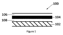
一実施形態において
繊維及び構造用樹脂材料を含む構造層、
ダンピング材料、
接合材料、
並びに表面層
を備える、ダンピング化済み(damped)複合材料を製造するための方法であって、
a) 接合材料をダンピング材料の第1の面と組み合わせるステップ、
b) 接合材料及びダンピング材料の第1の面を構造層と組み合わせるステップ、
c) 表面層をダンピング材料の第2の面と組み合わせるステップ
を含む、上記方法が提供される。
A structural layer comprising in one embodiment fibers and a structural resin material,
Dumping material,
Bonding material,
And a method for producing a damped composite material comprising a surface layer,
a) combining the bonding material with the first surface of the damping material,
b) combining the first surface of the bonding material and the damping material with the structural layer,
c) the above method is provided comprising the step of combining the surface layer with the second surface of the damping material.
航空機の胴体の表層に埋め込まれた粘弾性ダンピング材料は、典型的には、−50℃という低い温度に晒されるであろう。したがって、使用温度で必要とされるダンピング特性を達成する材料は、室温でも大きく変形できるようになっており、したがって、ATLレイアップのときに使用される高い張力とは適合しない。さらに、既存材料の製造に活用されている製造方法もまた、ダンピング材料用にはやはり適さない高い張力及び圧力を要する。したがって、上記の制約を克服し、ATL用に適合した粘弾性ダンピング材料、及びこうした粘弾性ダンピング材料を製造する方法を提供する必要性が存在する。 Viscoelastic damping material embedded in the surface of the fuselage of an aircraft will typically be exposed to temperatures as low as -50 <0> C. Thus, materials that achieve the required damping properties at the temperature of use are able to deform significantly even at room temperature, and thus are not compatible with the high tensions used during ATL layup. Furthermore, the manufacturing methods utilized for the production of existing materials also require high tensions and pressures which are also not suitable for damping materials. Therefore, there is a need to overcome the above limitations and provide a viscoelastic damping material adapted for ATL and a method of manufacturing such a viscoelastic damping material.
ダンピング材料は、室温で非常に弾性であり、取り扱いのときに容易に変形する。固結処理用ローラーを通過させること等、従来の手段を用いてダンピング材料又はダンピング層を構造層に施用する場合、ローラーによりダンピング材料に力を加えて、ダンピング材料を顕著に変形させる。ダンピング材料が固結処理用ローラーを通過して構造層に接着するとすぐに、ダンピング材料が弛緩して原形になり、構造層の許容されないひずみが生じる。本発明においては、ダンピング材料と構造層との間への接合材料の使用により、ダンピング材料と構造層との間の接着を増大させる。こうした接着の増大は、ダンピング材料を構造層に施用するのに必要な力を低減し、ダンピング材料中の張力についても低減し、これにより、望ましくない構造層のあらゆる変形をなくす。ATLによる堆積中にダンピング材料が欠損のない状態のままになるような十分な接着を伴ってダンピング材料を施用することが必要であり、こうした施用は、接合材料の使用でもって層間の接着を増大させることにより、達成することができる。 The damping material is very elastic at room temperature and deforms easily during handling. If the damping material or damping layer is applied to the structural layer using conventional means, such as passing through a consolidation treatment roller, the roller exerts a force on the damping material to significantly deform the damping material. As soon as the damping material passes through the consolidation roller and adheres to the structural layer, the damping material relaxes and unfolds, resulting in unacceptable distortion of the structural layer. In the present invention, the use of a bonding material between the damping material and the structural layer increases the adhesion between the damping material and the structural layer. Such an increase in adhesion reduces the force required to apply the damping material to the structural layer and also reduces the tension in the damping material, thereby eliminating any deformation of the structural layer which is undesirable. It is necessary to apply the damping material with sufficient adhesion so that the damping material remains free of defects during deposition by ATL, such application increases the adhesion between the layers with the use of bonding material Can be achieved by
一実施形態において、ダンピング材料、接合材料、並びに、繊維及び構造用樹脂材料を含む構造層を含む、ダンピング化済み複合材料が提供される。 In one embodiment, a dumped composite material is provided that includes a damping material, a bonding material, and a structural layer including fibers and structural resin material.
一実施形態において、ダンピング材料の第1の面上の接合材料、及びダンピング材料の第2の面上の表面層を有するダンピング材料を含む、ダンピング化済み複合材料であって、第1の面上の接合材料が、繊維及び構造用樹脂材料を含む構造層と接触している、上記ダンピング化済み複合材料が提供される。 In one embodiment, a damped composite material comprising: a bonding material on a first side of a damping material; and a damping material having a surface layer on a second side of the damping material, wherein the damping material is on a first side The above-mentioned dumped composite material is provided, wherein the bonding material is in contact with a structural layer comprising fibers and a structural resin material.
一実施形態において、接合材料は樹脂の層を含み得、樹脂は、構造層中の樹脂と同じ若しくは実質的に同じ組成物であってもよいし、又は、構造用樹脂としての使用に適した任意の樹脂から選択することもできる。好ましくは、接合材料は、熱硬化性樹脂である。好ましくは、接合材料は、1g/m2から50g/m2までの面積重量、又はより好ましくは4〜30g/m2の面積重量、又はより好ましくは6〜20g/m2の面積重量、又はさらにより好ましくは6〜10g/m2の面積重量を有する樹脂フィルムとして施用される。 In one embodiment, the bonding material may comprise a layer of resin, which may be the same or substantially the same composition as the resin in the structural layer, or suitable for use as a structural resin It can also be selected from any resin. Preferably, the bonding material is a thermosetting resin. Preferably, the bonding material, the area weight of from 1 g / m 2 to 50 g / m 2, or more preferably the area weight of 4~30g / m 2, or more preferably the area weight of 6~20g / m 2, or Even more preferably, it is applied as a resin film having an area weight of 6 to 10 g / m 2 .
好ましくは、接合材料樹脂は、熱硬化性樹脂を含む。熱硬化性樹脂は、フェノール−ホルムアルデヒド、尿素−ホルムアルデヒド、1,3,5−トリアジン−2,4,6−トリアミン(メラミン)、ビスマレイミド、エポキシ樹脂、ビニルエステル樹脂、ベンゾオキサジン樹脂、ポリエステル、不飽和ポリエステル、シアン酸エステル樹脂、又はこれらの混合物といった樹脂等、複合体製造における使用のために当技術分野で従来公知の熱硬化性樹脂から選択することができる。特に好ましいのは、エポキシ樹脂、例えば一官能性、二官能性又は三官能性又は四官能性のエポキシ樹脂である。好ましい二官能性エポキシ樹脂には、ビスフェノールFのジグリシジルエーテル(例えば、Araldite GY281)、ビスフェノールAのジグリシジルエーテル、ジグリシジルジヒドロキシナフタレン及びこれらの混合物が挙げられる。非常に好ましいエポキシ樹脂は、骨格中に少なくとも1つのメタ置換フェニル環を有する三官能性エポキシ樹脂、例えばAraldite MY0600である。好ましい四官能性エポキシ樹脂は、テトラグリシジルジアミノジフェニルメタン(例えば、Araldite MY721)である 二官能性エポキシ樹脂及び三官能性エポキシ樹脂の配合物もまた、非常に好ましい。熱硬化性樹脂は、1つ又は複数の硬化剤も含み得る。 Preferably, the bonding material resin contains a thermosetting resin. Thermosetting resins include phenol-formaldehyde, urea-formaldehyde, 1,3,5-triazine-2,4,6-triamine (melamine), bismaleimide, epoxy resin, vinyl ester resin, benzoxazine resin, polyester, Resins, such as saturated polyesters, cyanate ester resins, or mixtures thereof, can be selected from thermosetting resins conventionally known in the art for use in composite production. Particularly preferred are epoxy resins, such as monofunctional, difunctional or trifunctional or tetrafunctional epoxy resins. Preferred difunctional epoxy resins include diglycidyl ethers of bisphenol F (e.g., Araldite GY 281), diglycidyl ethers of bisphenol A, diglycidyl dihydroxy naphthalene and mixtures thereof. Highly preferred epoxy resins are trifunctional epoxy resins having at least one meta-substituted phenyl ring in the backbone, such as Araldite MY0600. Also preferred is a blend of difunctional and trifunctional epoxy resins in which the preferred tetrafunctional epoxy resin is tetraglycidyldiaminodiphenylmethane (eg Araldite MY721). The thermosetting resin may also include one or more curing agents.
適切な硬化剤には、無水物、特にポリカルボン酸無水物、アミン、特に芳香族アミン、例えば1,3−ジアミノベンゼン、4,4’−ジアミノジフェニルメタン、並びに特にスルホン、例えば4,4’−ジアミノジフェニルスルホン(4,4’DDS)及び3,3’−ジアミノジフェニルスルホン(3,3’DDS)、並びにフェノール−ホルムアルデヒド樹脂が挙げられる。好ましい硬化剤は、アミノスルホン、特に4,4’DDS及び3,3’DDSである。 Suitable curing agents include anhydrides, in particular polycarboxylic acid anhydrides, amines, in particular aromatic amines, such as 1,3-diaminobenzene, 4,4'-diaminodiphenylmethane, and in particular sulfones, such as 4,4'-. Diaminodiphenyl sulfone (4,4'DDS) and 3,3'-diaminodiphenyl sulfone (3,3'DDS), and phenol-formaldehyde resins are included. Preferred curing agents are aminosulphones, in particular 4,4'DDS and 3,3'DDS.
接合材料樹脂は、ダンピング材料に施用した後、構造層と接触させることができる。こうした接触は、ダンピング材料が固結処理用ローラーを通過するときに、さらなる拘束をもたらすことにより、ダンピング材料の変形を有利に低減する。 The bonding material resin can be brought into contact with the structural layer after application to the damping material. Such contact advantageously reduces the deformation of the damping material by providing further restraint as the damping material passes through the consolidation treatment roller.
代替的実施形態において、接合材料樹脂を構造層に施用した後、構造層と接触させることもできる。接合材料樹脂の施用は、複合材料の樹脂含量を増大させるため、樹脂含量の増大に応じて構造用樹脂の量を低減することが好ましい。 In an alternative embodiment, the bonding material resin can be applied to the structural layer and then contacted with the structural layer. The application of the bonding material resin is preferred to reduce the amount of structural resin in accordance with the increase of the resin content in order to increase the resin content of the composite material.
一実施形態において、接合材料は、樹脂材料の特性を改善するための添加剤を含み得る。こうした添加剤には、流動性調節用添加剤、紫外線吸収剤、充填剤、例えばシリカ、タルク、マイカ、黒鉛、導電性粒子、例えば炭素粒子、黒鉛粒子若しくは金属粒子、又は、フィラメント、顔料、難燃剤、強靭化剤、例えばコアシェル型ゴム、及び加工剤を挙げることができる。特に、ダンピング材料と構造層との接着を向上するための添加剤が選択され得る。 In one embodiment, the bonding material may include an additive to improve the properties of the resin material. Such additives include flow control additives, UV absorbers, fillers such as silica, talc, mica, graphite, conductive particles such as carbon particles, graphite particles or metal particles, or filaments, pigments, Mention may be made of flame retardants, toughening agents such as core-shell rubbers, and processing agents. In particular, additives may be selected to improve the adhesion between the damping material and the structural layer.
一実施形態において、接合材料は、構造用樹脂と同じ樹脂を含み得る。構造層は、接合材料を含み、ダンピング層と構造層との適切な接着を達成させ、必要なローラー力低減を実現することになるように十分な構造用樹脂を接合表面上に伴わせて、形成することができる。適切な接着とは、構造用繊維において視認可能なひずみが発生することがなく、且つ、ダンピング材料がATLレイアップ中に視認できるほど脱離することもなく、ダンピング材料を構造層に接着することができる場合であると考えられる。 In one embodiment, the bonding material may comprise the same resin as the structural resin. The structural layer comprises a bonding material, with sufficient structural resin on the bonding surface to achieve proper adhesion between the damping layer and the structural layer and to achieve the required reduction in roller force, It can be formed. Proper bonding means bonding the damping material to the structural layer without visible distortion in the structural fiber and without the damping material being visibly detached during ATL layup. Is considered to be the case when
一実施形態において、接合材料の厚さが、構造層への施用時におけるダンピング材料のひずみを予防するように選択される。接合材料は好ましくは、ダンピング材料又は構造層のいずれかに層として施用される。接合材料の層は、組み立てられたダンピング化済み複合材料中において構造層とダンピング材料との間に必要となる接着を達成するのに十分な厚さを有する。好ましくは、接合材料は、0.05mmから1mmまでの、又は好ましくは0.1mmから0.5mmまでの厚さを伴わせて施用される。 In one embodiment, the thickness of the bonding material is selected to prevent distortion of the damping material upon application to the structural layer. The bonding material is preferably applied as a layer to either the damping material or the structural layer. The layer of bonding material has a thickness sufficient to achieve the required adhesion between the structural layer and the damping material in the assembled dumped composite. Preferably, the bonding material is applied with a thickness of 0.05 mm to 1 mm, or preferably 0.1 mm to 0.5 mm.
好ましい実施形態において、接合材料は、後述のDubois試験に従って測定されたときに0.1から0.2までの範囲の接着をもたらし、さらに、硬化前の構造層とダンピング材料との接着は、0.1から0.45の間である。 In a preferred embodiment, the bonding material provides an adhesion in the range of 0.1 to 0.2 when measured according to the Dubois test described below, and further, the adhesion between the structural layer and the damping material before curing is 0. Between .1 and 0.45.
接着は、「プリプレグの粘着の実験的分析(Experimental analysis of prepreg tack)」Duboisら、(LaMI)UBP/IFMA、2009年3月5日で開示された方法に従って、材料について測定することができる。しかしながら、粘着性を測定する好ましい方法は、次のとおりである。 Adhesion can be measured on materials according to the method disclosed in "Experimental analysis of prepreg tack" Dubois et al., (LaMI) UBP / IFMA, March 5, 2009. However, the preferred method of measuring tack is as follows.
材料の粘着性は、テクスチャーアナライザー式試験法を用いて測定される。この方法では、縦15mm横15mmという寸法になった材料の試料をStable Micro Systems、UKから調達するTA.XT Plus Texture Analyserという粘着性測定機器の試験テーブルにしっかりと固定することが必要になる。テクスチャーアナライザーは、直径6mmの円筒形ステンレス鋼プローブを備えており、このプローブは、材料の表面上に10Nの力で30秒加圧される。次いで、プローブが、0.5mm/sの速度で10mmの距離まで垂直に抜き出される。プローブに接続されたロードセルが、接着のピーク力を記録する。テクスチャーアナライザー試験法は、23℃という一定温度の環境中で実施して、プローブ及び試料が同様に23℃の温度になることを保証する。 The tack of the material is measured using a texture analyzer test method. In this method, a sample of material 15 mm long x 15 mm in size is procured from Stable Micro Systems, UK. It is necessary to be firmly fixed to the test table of the adhesion measuring instrument called XT Plus Texture Analyzer. The texture analyzer comprises a cylindrical stainless steel probe 6 mm in diameter, which is pressurized for 30 seconds with a force of 10 N on the surface of the material. The probe is then withdrawn vertically at a speed of 0.5 mm / s to a distance of 10 mm. A load cell connected to the probe records the peak force of adhesion. The texture analyzer test method is performed in a constant temperature environment of 23 ° C. to ensure that the probe and sample are also at a temperature of 23 ° C.
一実施形態において、ダンピング化済み複合体が、単一のATL装置によって同時に組み立てられて堆積される。最初に、構造層が、ATL装置のヘッド部内のローラーにより型表面上に堆積される。次いで直ちに、ダンピング材料が、同じATLヘッド部に統合された追加ローラーを用いて構造層上に堆積される。上記一実施形態のダンピング材料は、表面粘着性を求めて構造層と表面層との接着を促進するための接合材料を含む。接合材料の裏当てが、構造層上への堆積前に取り除かれ、表面層裏当てが好ましくは、堆積後に取り除かれると、ATLローラーの張力からダンピング材料が防護される。任意選択により、ダンピング材料及び構造層は、同じロールに貯蔵し、ダンピング材料と構造層のそれぞれにある裏当て層によって隔てておいて、堆積前に分離することができる。上記特質の実施形態は、構造層がATLによって堆積されるとすぐに、型表面が繊維を拘束して、ダンピング材料中の何らかの張力により繊維の整列が乱れるのを予防するという点で、有利である。 In one embodiment, dumped complexes are simultaneously assembled and deposited by a single ATL device. First, a structural layer is deposited on the mold surface by a roller in the head of the ATL device. The damping material is then immediately deposited on the structural layer with the aid of an additional roller integrated in the same ATL head. The damping material of the above embodiment includes a bonding material for promoting surface adhesion to promote adhesion between the structural layer and the surface layer. The backing of the bonding material is removed prior to deposition on the structural layer, and preferably the surface layer backing is removed after deposition, protecting the damping material from the tension of the ATL roller. Optionally, the damping material and the structural layer can be stored in the same roll, separated by a backing layer on each of the damping material and the structural layer, and separated prior to deposition. Embodiments of the above character are advantageous in that the mold surface restrains the fibers as soon as the structural layer is deposited by ATL, to prevent any tension in the damping material from disturbing the alignment of the fibers. is there.
上述したように、ダンピング材料は、室温で柔らかい材料から製造されており、したがって、ダンピング材料はしばしば、貯蔵中にダンピング材料がダンピング材料自体に接着するのを予防するための粉体塗膜を備えている。典型的にはタルクが、上記の予防を目的として使用されるが、タルクは、汚染物質であると考えられることもある。本発明の一実施形態において、粉体は、使用前に溶媒浴を通過させることにより、ダンピング材料から取り除くことができる。代替的実施形態において、溶媒浴の複雑さの増大は、接合材料又は接合層をダンピング材料に施用して、粉体を包み込むことにより構造層から粉体を隔離する一方で、ダンピング材料と構造層との十分な接着を実現するという態様で、接合材料又は接合層を使用することにより、克服される。
As described above, the damping material is manufactured from a soft material at room temperature, therefore, the damping material is often provided with a powder Karadanurimaku for damping material during storage to prevent the adhesion of the damping material itself ing. Although talc is typically used for the above-mentioned prevention purposes, talc may also be considered as a contaminant. In one embodiment of the present invention, powder, by passing the solvent bath before use, it can be removed from the damping material. In an alternative embodiment, the increase in complexity of the solvent bath, the bonding material or bonding layer is applied to the damping material, while isolating the powder from the structural layer by wrapping the powder, the damping material and the structure layer It is overcome by using a bonding material or layer in the manner of achieving sufficient adhesion with.
本発明の代替的実施形態において、ダンピング層の粉体塗膜は、接合材料及び/又は構造用材料樹脂に対して反応性である粉体を含む。好ましくは、粉体は、樹脂又は硬化剤を含む。粉体は例えば、結晶性エポキシ、結晶性硬化剤、又は粉砕された硬化済み樹脂であってよい。反応性粉体塗膜は、ダンピング材料が、ダンピング材料自体にくっつくことなく圧延されることを可能にするものであり、マトリックスとの間に結合が形成される硬化の間に、マトリックス中に取り込まれた状態になる。
In an alternative embodiment of the present invention, powder Karadanurimaku damping layer comprises a powder which is reactive toward bonding material and / or structural material resin. Preferably, powder comprises a resin or curing agent. Powder, for example, crystalline epoxy, crystalline curing agent, or a milled cured resin. Reactive powder Karadanurimaku the damping material, which enables it to be rolled without sticking to the damping material itself, during curing the bond between the matrix is formed, incorporated into a matrix It will be
一実施形態において、接合材料は、ベール、スクリム又は不織布型層を含み得る。一実施形態において、ベールをダンピング材料に接着した後、構造層と接触させる。ダンピング材料より高い弾性率を有するベールが選択される場合、ダンピング材料が固結処理用ローラーを通過すると、ダンピング材料がダンピング材料の変形を低減する。したがって、好ましくは、ダンピング複合体は、ダンピング材料より顕著に高い弾性率と、固結処理用ローラー及びATLヘッド部を通過するときの変形を耐え切るのに十分な引張特性とを示す、ベールをさらに備える。十分な引張特性は、自動式テープレイアップの施用又は固結中に受ける張力の下で配置されたときに、顕著な面内伸長が発生せず、ベールがその形状を実質的に保持することを意味する。ベールは、織物型マット、スパンレース型マット又はランダム型マットの状態になっている、ガラス繊維織物又はベール、並びにポリエステル及びナイロン等のポリマー等、いくつかの可能性から選択することができる。マットを形成するように無作為に一緒にして形成された材料の短繊維を含むベールは、格子として配列された連続繊維がもたらすのと同様に、優れた配列体をもたらす。例示的なベールには、Brellingroth GmBHによって製造されているBafatex、又はTechnical Fibre Products Limitedによって製造されているOptimatが挙げられる。ベールは、0.5g/m2から5g/m2までの、好ましくは1g/m2から3g/m2までの範囲の面積重量を有し得る。 In one embodiment, the bonding material may comprise a bale, scrim or non-woven type layer. In one embodiment, the bale is bonded to the damping material and then contacted with the structural layer. If a bale having a higher modulus of elasticity than the damping material is selected, the damping material reduces the deformation of the damping material as it passes through the consolidation treatment roller. Thus, preferably, the damping composite exhibits a significantly higher modulus than the damping material and tensile properties sufficient to resist deformation as it passes through the consolidation roller and the ATL head. Further equipped. Sufficient tensile properties are such that when placed under tension received during application or consolidation of an automatic tape layup, no significant in-plane elongation occurs and the bale substantially retains its shape Means The bale can be selected from several possibilities, such as glass fiber fabric or bale, and polymers such as polyester and nylon, in the form of woven mats, spunlaced mats or random mats. A bale containing short fibers of material randomly formed together to form a mat provides a superior alignment, as does continuous fibers arranged in a grid. Exemplary bales include Bafatex manufactured by Brellingroth GMBH, or Optimat manufactured by Technical Fiber Products Limited. The bale may have an areal weight ranging from 0.5 g / m 2 to 5 g / m 2 , preferably from 1 g / m 2 to 3 g / m 2 .
代替的実施形態において、ベールは、ダンピング材料の施用前に構造層に配置することもでき、こうした状態になっているときは、ベールが、ダンピング材料に隣接した接合材料の樹脂を保持し、この結果として接着を増大させ、必要な固結力を低下させる。したがって、一実施形態において、接合材料は、樹脂とベールの両方を含み得る。 In an alternative embodiment, the bale can be placed on the structural layer prior to application of the damping material, and when in this state, the bale holds the resin of the bonding material adjacent to the damping material, As a result, the adhesion is increased and the necessary consolidation is reduced. Thus, in one embodiment, the bonding material may include both a resin and a bale.
一実施形態において、ダンピング材料は、粘弾性材料を含み、この粘弾性材料は、熱可塑性物質であってもよいし、ポリウレタンであってもよいし、又は、アクリルゴム若しくはラテックスゴム、スチレン−ブタジエンゴム、イソプレン由来、クロロプレン由来若しくはイソブチレン由来のゴム、又はこれらのコポリマーを含めて、他の高ダンピング化済みポリマーであってもよい。好ましくは、ダンピング材料は、加硫ゴムを含む。例示的なダンピング材料には、Smactane、Smacwrap及びSmacwrap ST(Smac、Toulon、France)が挙げられる。 In one embodiment, the damping material comprises a visco-elastic material, which may be a thermoplastic or polyurethane, or an acrylic or latex rubber, styrene-butadiene Other highly damped polymers may be included, including rubber, isoprene derived, chloroprene derived or isobutylene derived rubber, or copolymers thereof. Preferably, the damping material comprises a vulcanized rubber. Exemplary damping materials include Smactane, Smacwrap and Smacwrap ST (Smac, Toulon, France).
一実施形態において、ダンピング材料は、0.05mmから1mmまでの厚さ、又は好ましくは0.05mmから0.5mmまでの厚さ、又は好ましくは0.3mmから0.1mmまでの厚さ、又はより好ましくは0.1mmから0.2mmまでの厚さ、又はさらにより好ましくは0.1、0.12若しくは0.2mmのいずれかの厚さ、及び/又は上記範囲の組合せの厚さを有する連続シートである。 In one embodiment, the damping material has a thickness of 0.05 mm to 1 mm, or preferably 0.05 mm to 0.5 mm, or preferably 0.3 mm to 0.1 mm, or More preferably with a thickness of 0.1 mm to 0.2 mm, or even more preferably with a thickness of either 0.1, 0.12 or 0.2 mm and / or a combination of the above ranges It is a continuous sheet.
一実施形態において、ダンピング材料は、50g/m2から1400g/m2までの面積重量、若しくは好ましくは75g/m2から950g/m2までの面積重量、若しくは好ましくは100g/m2から300g/m2までの面積重量、若しくはさらにより好ましくは110g/m2から240g/m2までの、及び/又は上記範囲の組合せの面積重量を有する連続シートである。 In one embodiment, the damping material, the area weight from 50 g / m 2 to 1400 g / m 2, or preferably the area weight from 75 g / m 2 to 950 g / m 2, or preferably from 100g / m 2 300g / area weight of up to m 2, or even more preferably from 110g / m 2 to 240 g / m 2, and / or a continuous sheet having an area weight of the combination of the above-mentioned range.
一実施形態において、ASTM D1456−86(2010)標準試験法によって評価したときのダンピング材料が、300%から800%の間の、又はより好ましくは400%から600%の間の、又はさらにより好ましくは450%から500%の間の最大伸びを有する。 In one embodiment, the damping material as assessed by ASTM D 1456-86 (2010) Standard Test Method is between 300% and 800%, or more preferably, between 400% and 600%, or even more preferably. Have a maximum elongation between 450% and 500%.
ダンピング材料の伸びは、本明細書で記述した垂直吊り下げ式試験法を用いることによっても測定することができる。垂直吊り下げ式試験法は、本出願の目的に関する伸びを測定する好ましい方法である。ダンピング材料の伸びは、30×150×0.1mmという寸法になったダンピング材料の一部を垂直に吊り下げ、質量を材料底部の端部に適用することによって測定される。次いで、合計で5Nに到達するまで0.5Nの質量を順次適用する。無変形時点での初期長さに対する百分率としての伸びは、毎回の質量増大によって測定することができる。得られた伸びは、適切な測定システム、例えば、ダンピング材料に対して平行に吊り下げられた定規を用いて測定する。本発明のダンピング材料は好ましくは、1.5Nの質量を適用した場合に10%から30%までの、又はより好ましくは18%から27%までの伸びを示す。3Nの質量を適用した場合、ダンピング材料は好ましくは、45%から60%までの、又はより好ましくは47%から55%までの伸びを示す。4.5Nの質量を適用した場合、ダンピング材料は好ましくは、120%から160%までの、又はより好ましくは125%から145%までの伸びを示す。 The elongation of the damping material can also be measured by using the vertical hanging test method described herein. The vertically suspended test method is a preferred method of measuring elongation for the purpose of the present application. The elongation of the damping material is measured by vertically suspending a portion of the damping material sized 30 × 150 × 0.1 mm and applying a mass to the end of the bottom of the material. Then, sequentially apply a mass of 0.5 N until a total of 5 N is reached. The elongation as a percentage of the initial length at the point of no deformation can be measured by the mass increase at each time. The elongation obtained is measured using a suitable measuring system, for example a ruler suspended parallel to the damping material. The damping material of the present invention preferably exhibits an elongation of 10% to 30%, or more preferably 18% to 27% when a mass of 1.5 N is applied. When a mass of 3N is applied, the damping material preferably exhibits an elongation of 45% to 60%, or more preferably 47% to 55%. When a mass of 4.5 N is applied, the damping material preferably exhibits an elongation of 120% to 160%, or more preferably 125% to 145%.
一実施形態において、表面層は、粘着性が増大した成型材料をもたらすために繊維型材料の層の外面に施用することができる、樹脂を含む。一実施形態において、表面層は、構造用樹脂と同じ樹脂を含み得、又は、構造用樹脂としての使用に適した任意の樹脂から選択され得る。粘着性の増大により、隣接した材料の層がレイアップ中に一緒に保持されるのが補助される。追加の樹脂層により、繊維型強化材の別の層を成型材料に取り付けることも可能になる。複合材料テープが、ATLシステムと適合する少なくとも1つの粘着質表面を有することが、好ましい。 In one embodiment, the surface layer comprises a resin that can be applied to the outer surface of the layer of fibrous material to provide a molded material with increased tack. In one embodiment, the surface layer may comprise the same resin as the structural resin or may be selected from any resin suitable for use as a structural resin. The increase in tack helps to hold adjacent layers of material together during layup. The additional resin layer also makes it possible to attach another layer of fibrous reinforcement to the molding material. It is preferred that the composite tape have at least one sticky surface compatible with the ATL system.
本明細書で前述したテクスチャーアナライザー試験法によって試験される本発明の実施形態は、2Nから25Nまでの接着のピーク力、若しくはより好ましくは5Nから20Nまでの接着のピーク力、若しくはより好ましくは10Nから20Nまでの接着のピーク力、若しくはさらにより好ましくは5Nから10Nまでの接着のピーク力、及び/又は上記範囲の組合せの接着のピーク力を示す。 Embodiments of the invention to be tested by the Texture Analyzer Test Method described herein above have a peak power of adhesion from 2N to 25N, or more preferably a peak power of adhesion from 5N to 20N, or more preferably 10N. Peak power of adhesion from 20N to 20N, or even more preferably peak power of adhesion of 5N to 10N, and / or combinations of the above ranges.
一実施形態において、ダンピング材料は、開口されていない連続シートであり、したがって、一旦ダンピング材料が構造層に施用されたら、樹脂が表面上に存在しないことになり、この結果として、粘着性付与層を追加できるようになる。ダンピング材料は好ましくは、無変形状態になっているときに不透過性且つ/又は連続的である。ダンピング材料中のスリット加工部又はその他の断絶部は、硬化済み積層品に組み込まれている場合、硬化済み積層品のノイズ減衰特性を低減する恐れがあり、したがって、無変形状態になっているときに開口又はスリット加工されていないダンピング層を使用することが、好ましい。 In one embodiment, the damping material is a continuous sheet that is not open so that once the damping material is applied to the structural layer, no resin will be present on the surface, resulting in a tackifying layer You will be able to add The damping material is preferably impermeable and / or continuous when in the undeformed state. Slits or other breaks in the damping material, when incorporated into the cured laminate, may reduce the noise attenuation properties of the cured laminate, and thus be undeformed It is preferred to use a damping layer that is not apertured or slitted.
代替的実施形態において、ダンピング材料又はダンピング層は、接合材料又は構造層からダンピング層の表面まで移動し、この結果として粘着質表面を用意することを可能にするために、開口されていてもよい。 In an alternative embodiment, the damping material or layer may be open to allow it to move from the bonding material or structural layer to the surface of the damping layer, thus providing a sticky surface .
一実施形態において、表面層及び/又は接合層は、硬化性ゴムを含み得、例えば、モノマー単位であるブチル、クロロブチル、イソプレン、クロロプレン、ブタジエン、スチレン及びアクリロニトリル、並びに/又は、上記ゴムの組合せ、配合物若しくはコポリマーのいずれかを含む、ゴムを含み得る。このようなゴムは典型的には、接合層又は表面層として機能するのに十分な粘着性を有する。このようなゴムの粘弾性もまた、複合材料のダンピング性能にさらに寄与する。 In one embodiment, the surface layer and / or the bonding layer may comprise a curable rubber, for example the monomer units butyl, chlorobutyl, isoprene, chloroprene, butadiene, styrene and acrylonitrile, and / or combinations of the above rubbers, It can include a rubber, including either a blend or a copolymer. Such rubbers typically have sufficient tack to function as a bonding or surface layer. The visco-elastic properties of such rubbers also contribute to the damping performance of the composite material.
ダンピング化済み複合材料がATLのために、特にAFP堆積のために使用される場合、レイアップされた積層品の全体にわたるダンピング層中には、一連の断絶部又は空隙が存在する。こうした断絶部は、ATL用又はAFP用の幅へのダンピング層の切断から生じる。硬化中に構造層及び/又は接合層として硬化性ゴムを使用することにより、ダンピング層がスリット加工された場所である、隣接したテープの長さの間にわたる断絶部又は空隙を充填する。こうした充填により、積層体構造の全体にわたるゴム材料の連続層が生成され、この結果としてダンピングが向上する。表面層及び/又は接合層としての使用のための例示的な硬化性ゴムには、WO2010/079319で開示された硬化性ゴムが挙げられる。 When dumped composites are used for ATL, especially for AFP deposition, there is a series of breaks or voids in the damping layer throughout the layup of the laminate. These breaks result from the cutting of the damping layer to a width for ATL or AFP. The use of curable rubber as a structural layer and / or bonding layer during curing fills in the breaks or voids between the lengths of adjacent tapes where the damping layer is slit. Such filling produces a continuous layer of rubber material throughout the laminate structure, which results in improved damping. Exemplary curable rubbers for use as surface layers and / or bonding layers include the curable rubbers disclosed in WO 2010/079319.
一実施形態において、表面層は、樹脂フィルム、スプレー堆積又は溶媒浴により、ダンピング材料に施用することができる。一実施形態において、樹脂フィルムの使用が好ましい。一実施形態において、表面層は、1〜50g/m2の、又はより好ましくは4〜30g/m2の、又はより好ましくは6〜20g/m2の、又はさらにより好ましくは6〜10g/m2の樹脂フィルムである。 In one embodiment, the surface layer can be applied to the damping material by resin film, spray deposition or solvent bath. In one embodiment, the use of a resin film is preferred. In one embodiment, the surface layer is 1 to 50 g / m 2 , or more preferably 4 to 30 g / m 2 , or more preferably 6 to 20 g / m 2 , or even more preferably 6 to 10 g / m 2 It is a resin film of m 2 .
一実施形態において、表面層は、ベール又は裏当てシートを備える。表面層は、裏当て紙上の樹脂フィルムであってもよく、後には、この樹脂フィルムをダンピング材料に施用した後、ダンピング材料を構造層に接着することになる。固結処理用ローラーによってダンピング材料が構造層に接着されるとき、裏当て層は、ダンピング材料の表面上に残留している。 In one embodiment, the surface layer comprises a bale or backing sheet. The surface layer may be a resin film on a backing paper, which will later be adhered to the structural layer after the resin film is applied to the damping material. When the damping material is adhered to the structural layer by the consolidation rollers, the backing layer remains on the surface of the damping material.
裏当て層材料は、裏当て層材料がダンピング材料より剛性であり、且つ、固結処理用ローラーの張力を耐え抜くことができ、この結果として、ダンピング材料がローラーを通過するときにダンピング材料を防護し、ダンピング材料のひずみを低減するように選択される。ベールは、接合材料中に組み込まれたベールとほとんど同じ機能を果たし、したがって、接合材料との併用に適した任意のベールは、表面層との併用にも適しているであろう。 The backing layer material is more rigid than the damping material and can withstand the tension of the consolidation roller, as a result of which it protects the damping material as it passes through the roller And selected to reduce the strain of the damping material. The bale performs much the same function as the bale incorporated into the bonding material, so any bale suitable for use with the bonding material would also be suitable for use with the surface layer.
一実施形態において、表面層又は構造層は、裏当て層を備えていてもよく、裏当て層は、紙又はポリマーシートであり得る。一実施形態において、紙裏当て層を取り除き、ポリマーシートによって置きかえた後、スリット加工が行われる。 In one embodiment, the surface or structural layer may comprise a backing layer, which may be a paper or a polymer sheet. In one embodiment, after the paper backing layer has been removed and replaced by a polymer sheet, slitting is performed.
構造層は、構造用樹脂及び構造用繊維を含む。構造用繊維は、合成繊維若しくは天然繊維、又は、構造用樹脂組成物と組み合わせることができる材料若しくは材料の組合せの任意の他の形態を含み得る。例示的な繊維には、ガラス、炭素、黒鉛、ホウ素、セラミックス及びアラミドが挙げられる。好ましい繊維は、炭素繊維及びガラス繊維である。ハイブリッド型繊維又は混合繊維システムもまた、想定され得る。繊維型強化剤内部の繊維の重量は一般に、20〜10000g/m2の、好ましくは50g/m2から800〜2500g/m2までの、さらにより好ましくは1200g/m2から2400g/m2までの、特に好ましくは150g/m2から600g/m2までの、及び/又は上記範囲の組合せである。トウ1個当たりの炭素フィラメントの数は、3000本から100,000本までであり得、さらに好ましくは6,000本から80,000までであり得、最も好ましくは12,000本から40,000本までであり得、及び/又は上記範囲の組合せであり得る。本発明において活用されるトウは、複数の個々のフィラメントから構成されている。単一のトウ内には、個々のフィラメントが何千何万も存在し得る。トウ及びトウ内部のフィラメントは一般に、個々のフィラメントが実質的に平行に整列した状態になって一方向に向いている。典型的には、トウ内のフィラメントの数は、2,500から10,000〜50,000以上までの範囲であり得る。典型的には、繊維は、円形又はほぼ円形の断面を有し、ここでは、炭素の直径が3μmから20μmまでの、好ましくは5μmから12μmまでの範囲になっている。ガラスを含めた他の繊維の場合、直径は、3μmから600μmまでの、好ましくは10μmから100μmまでの範囲であり得る。トウは好ましくは、一方向に向いており、ここで、トウどうしが実質的に平行になっており、且つ製造方向に整列している。 The structural layer contains structural resin and structural fibers. The structural fibers may comprise synthetic fibers or natural fibers or any other form of material or combination of materials that can be combined with the structural resin composition. Exemplary fibers include glass, carbon, graphite, boron, ceramics and aramids. Preferred fibers are carbon fibers and glass fibers. Hybrid type fibers or mixed fiber systems may also be envisaged. Weight of fibers within the fiber type reinforcement is generally of 20~10000g / m 2, preferably from 50 g / m 2 up to 800~2500g / m 2, still more preferably from 1200 g / m 2 to 2400 g / m 2 And particularly preferably 150 g / m 2 to 600 g / m 2 and / or combinations of the above ranges. The number of carbon filaments per tow may be from 3000 to 100,000, more preferably from 6,000 to 80,000, most preferably from 12,000 to 40,000. It may be up to book and / or may be a combination of the above ranges. The tow utilized in the present invention is comprised of a plurality of individual filaments. There can be tens of thousands of individual filaments in a single tow. The tow and the filaments within the tow are generally oriented in one direction with the individual filaments aligned substantially parallel. Typically, the number of filaments in the tow may range from 2,500 to 10,000 to 50,000 or more. Typically, the fibers have a circular or nearly circular cross section, where the carbon diameter is in the range of 3 μm to 20 μm, preferably 5 μm to 12 μm. For other fibers, including glass, the diameter may range from 3 μm to 600 μm, preferably from 10 μm to 100 μm. The tow is preferably oriented in one direction, wherein the tow is substantially parallel and aligned in the manufacturing direction.
構造用樹脂は好ましくは、熱硬化性樹脂である。熱硬化性樹脂は、フェノール−ホルムアルデヒド、尿素−ホルムアルデヒド、1,3,5−トリアジン−2,4,6−トリアミン(メラミン)、ビスマレイミド、エポキシ樹脂、ビニルエステル樹脂、ベンゾオキサジン樹脂、ポリエステル、不飽和ポリエステル、シアン酸エステル樹脂、又はこれらの混合物といった樹脂等、複合体製造における使用のために当技術分野で従来公知の熱硬化性樹脂から選択することができる。特に好ましいのは、エポキシ樹脂、例えば一官能性、二官能性又は三官能性又は四官能性のエポキシ樹脂である。好ましい二官能性エポキシ樹脂には、ビスフェノールFのジグリシジルエーテル(例えば、Araldite GY281)、ビスフェノールAのジグリシジルエーテル、ジグリシジルジヒドロキシナフタレン及びこれらの混合物が挙げられる。非常に好ましいエポキシ樹脂は、骨格中に少なくとも1つのメタ置換フェニル環を有する三官能性エポキシ樹脂、例えばAraldite MY0600である。好ましい四官能性エポキシ樹脂は、テトラグリシジルジアミノジフェニルメタン(例えば、Araldite MY721)である 二官能性及び三官能性のエポキシ樹脂の配合物もまた、非常に好ましい。本発明において使用されるエポキシ樹脂は、多官能性であり、すなわち、少なくとも二官能性、好ましくは三官能性又は四官能性を有する。本発明において使用されるエポキシ樹脂は好ましくは、100から1500までの範囲のEEW、好ましくは100から250までの範囲のEEWによって指し示される高い反応性を有する。 The structural resin is preferably a thermosetting resin. Thermosetting resins include phenol-formaldehyde, urea-formaldehyde, 1,3,5-triazine-2,4,6-triamine (melamine), bismaleimide, epoxy resin, vinyl ester resin, benzoxazine resin, polyester, Resins, such as saturated polyesters, cyanate ester resins, or mixtures thereof, can be selected from thermosetting resins conventionally known in the art for use in composite production. Particularly preferred are epoxy resins, such as monofunctional, difunctional or trifunctional or tetrafunctional epoxy resins. Preferred difunctional epoxy resins include diglycidyl ethers of bisphenol F (e.g., Araldite GY 281), diglycidyl ethers of bisphenol A, diglycidyl dihydroxy naphthalene and mixtures thereof. Highly preferred epoxy resins are trifunctional epoxy resins having at least one meta-substituted phenyl ring in the backbone, such as Araldite MY0600. Also preferred is a blend of difunctional and trifunctional epoxy resins in which the preferred tetrafunctional epoxy resin is tetraglycidyldiaminodiphenylmethane (eg Araldite MY721). The epoxy resins used in the present invention are multifunctional, i.e. at least difunctional, preferably trifunctional or tetrafunctional. The epoxy resin used in the present invention preferably has a high reactivity indicated by an EEW in the range of 100 to 1500, preferably in the range of 100 to 250.
適切な二官能性エポキシ樹脂については例として、ビスフェノールFのジグリシジルエーテル、ビスフェノールAのジグリシジルエーテル(任意選択により臭素化されている)、フェノール型及びクレゾール型エポキシノボラック、フェノール−アルデヒド付加体のグリシジルエーテル、脂肪族ジオールのグリシジルエーテル、ジグリシジルエーテル、ジエチレングリコールジグリシジルエーテル、芳香族エポキシ樹脂、脂肪族ポリグリシジルエーテル、エポキシ化オレフィン、臭素化樹脂、芳香族グリシジルアミン、複素環式グリシジルイミジン及びグリシジルアミド、グリシジルエーテル、フッ素化エポキシ樹脂、グリシジルエステル又はこれらの任意の組合せを主体としたものが挙げられる。 Examples of suitable difunctional epoxy resins include diglycidyl ethers of bisphenol F, diglycidyl ethers of bisphenol A (optionally brominated), phenolic and cresol epoxy novolacs, phenolic-aldehyde adducts Glycidyl ether, glycidyl ether of aliphatic diol, diglycidyl ether, diethylene glycol diglycidyl ether, aromatic epoxy resin, aliphatic polyglycidyl ether, epoxidized olefin, brominated resin, aromatic glycidyl amine, heterocyclic glycidyl imidine and Those based on glycidyl amide, glycidyl ether, fluorinated epoxy resin, glycidyl ester or any combination thereof are mentioned.
適切な三官能性エポキシ樹脂については例として、フェノール型及びクレゾール型エポキシノボラック、フェノール−アルデヒド付加体のグリシジルエーテル、芳香族エポキシ樹脂、脂肪族トリグリシジルエーテル、ジ脂肪族トリグリシジルエーテル、脂肪族ポリグリシジルアミン、複素環式グリシジルイミジン及びグリシジルアミド、グリシジルエーテル、フッ素化エポキシ樹脂又はこれらの任意の組合せを主体としたものを挙げることができる。適切な三官能性エポキシ樹脂は、MY0500及びMY0510(トリグリシジルパラ−アミノフェノール)、並びにMY0600及びMY0610(トリグリシジルメタ−アミノフェノール)という商標でHuntsman Advanced Materials(Monthey、Switzerland)から入手することができる。トリグリシジルメタ−アミノフェノールは、ELM−120という商標で住友化学株式会社(大阪、日本)からも入手することができる。 Examples of suitable trifunctional epoxy resins include: phenol type and cresol type epoxy novolac, glycidyl ether of phenol-aldehyde adduct, aromatic epoxy resin, aliphatic triglycidyl ether, dialiphatic triglycidyl ether, aliphatic poly Examples thereof include glycidyl amine, heterocyclic glycidyl imidine and glycidyl amide, glycidyl ether, fluorinated epoxy resin, or any combination thereof. Suitable trifunctional epoxy resins can be obtained from Huntsman Advanced Materials (Monthey, Switzerland) under the trademarks MY0500 and MY0510 (triglycidyl para-aminophenol) and MY0600 and MY0610 (triglycidyl meta-aminophenol) . Triglycidyl meta-aminophenol is also available from Sumitomo Chemical Co., Ltd. (Osaka, Japan) under the trademark ELM-120.
四官能性樹脂は、本発明の配合物のための多官能性樹脂としての使用のために好ましい樹脂であり、適切な四官能性エポキシ樹脂には、N,N,N’,N’−テトラグリシジル−m−キシレンジアミン(三菱ガス化学株式会社からはTetrad−Xという名称で市販、CVC ChemicalsからはErisys GA−240として市販)、及びN,N,N’,N’−テトラグリシジルメチレンジアニリン(例えば、Huntsman Advanced Materials製のMY0720及びMY0721)が挙げられる。その他の適切な多官能性エポキシ樹脂には、DEN438(Dow Chemicals、Midland、MI製)DEN439(Dow Chemicals製)、Araldite ECN1273(Huntsman Advanced Materials製)、Araldite ECN1299、及びAraldite MY9512(Huntsman Advanced Materials製)が挙げられる。 Tetrafunctional resins are preferred resins for use as multifunctional resins for the formulations of the present invention and suitable tetrafunctional epoxy resins include N, N, N ', N'-tetra Glycidyl-m-xylenediamine (commercially available from Mitsubishi Gas Chemical Co., Ltd. under the name Tetrad-X, commercially available from CVC Chemicals as Erisys GA-240), and N, N, N ', N'-tetraglycidylmethylenedianiline (Eg, MY0720 and MY0721 from Huntsman Advanced Materials). Other suitable multifunctional epoxy resins include DEN438 (Dow Chemicals, Midland, MI) DEN439 (Dow Chemicals), Araldite ECN 1273 (Huntsman Advanced Materials), Araldite ECN 1299, and Araldite MY 9512 (Huntsman Advanced Materials) Can be mentioned.
本発明の配合物は、ノボラック樹脂、末端封止済みのビスフェノールA型フェノール系樹脂等、他のエポキシ樹脂も含み得る。適切な樹脂については例として、ビスフェノールFのジグリシジルエーテル、ビスフェノールAのジグリシジルエーテル(任意選択により臭素化されている)、フェノール型及びクレゾール型エポキシノボラック、フェノール−アルデヒド付加体のグリシジルエーテル、脂肪族ジオールのグリシジルエーテル、ジグリシジルエーテル、ジエチレングリコールジグリシジルエーテル、芳香族エポキシ樹脂、脂肪族ポリグリシジルエーテル、エポキシ化オレフィン、臭素化樹脂、芳香族グリシジルアミン、複素環式グリシジルイミジン及びグリシジルアミド、グリシジルエーテル、フッ素化エポキシ樹脂、グリシジルエステル、又はこれらの任意の組合せを主体としたものが挙げられる。適切な樹脂の例は、Araldite EP820である。 The formulations of the present invention may also include other epoxy resins, such as novolac resins, end-capped bisphenol A-type phenolic resins, and the like. Examples of suitable resins include diglycidyl ethers of bisphenol F, diglycidyl ethers of bisphenol A (optionally brominated), phenolic and cresol epoxy novolacs, glycidyl ethers of phenolic-aldehyde adducts, fatty Ether of dibasic diol, diglycidyl ether, diethylene glycol diglycidyl ether, aromatic epoxy resin, aliphatic polyglycidyl ether, epoxidized olefin, brominated resin, aromatic glycidyl amine, heterocyclic glycidyl imidine and glycidyl amide, glycidyl Those based on ether, fluorinated epoxy resin, glycidyl ester, or any combination thereof can be mentioned. An example of a suitable resin is Araldite EP 820.
硬化剤は、配合物中のエポキシ樹脂基及びその他の原材料の架橋により、本発明の配合物の硬化を補助する。配合物中に存在する硬化剤及び/又は硬化剤促進剤の量は、約1重量%から約15重量%までの、より典型的には約2wt%から約12wt%までの範囲である。硬化剤材料は、脂肪族アミン若しくは芳香族アミン又は脂肪族アミンと芳香族アミンの各付加体、アミドアミン、ポリアミド、脂環式アミン、無水物、ポリカルボン酸ポリエステル、イソシアナート、フェノール主体型樹脂(例えば、フェノール型若しくはクレゾール型ノボラック樹脂、フェノールテルペン、ポリビニルフェノールのコポリマー等のコポリマー、又はビスフェノール−Aホルムアルデヒドコポリマー、又はビスヒドロキシフェニルアルカン等)、ジヒドラジド、スルホンアミド、ジアミノジフェニルスルホン等のスルホン、無水物、メルカプタン、イミダゾール、尿素、第三級アミン、BF3錯体又はこれらの混合物から選択することができる。特に好ましい硬化剤には、トリエチレンテトラミン、ジエチレントリアミンテトラエチレンペンタミン、シアノグアニジン及びジシアンジアミド等、変性及び無変性のポリアミン又はポリアミドが挙げられる。 Curing agents assist in curing the formulations of the present invention by crosslinking the epoxy resin groups and other raw materials in the formulation. The amount of curative and / or curative accelerator present in the formulation ranges from about 1 wt% to about 15 wt%, more typically from about 2 wt% to about 12 wt%. Curing agent materials are aliphatic amines or aromatic amines or adducts of aliphatic amines and aromatic amines, amidoamines, polyamides, alicyclic amines, anhydrides, polycarboxylic acid polyesters, isocyanates, phenol-based resins ( For example, phenol type or cresol type novolak resin, copolymer such as phenol terpene, copolymer of polyvinyl phenol, or bisphenol-A formaldehyde copolymer, or bishydroxyphenyl alkane, etc., sulfone such as dihydrazide, sulfonamide, diaminodiphenyl sulfone, anhydride , Mercaptans, imidazoles, ureas, tertiary amines, BF3 complexes or mixtures thereof. Particularly preferred curing agents include triethylenetetramine, diethylenetriaminetetraethylenepentamine, cyanoguanidine and dicyandiamide, and modified and non-modified polyamines or polyamides.
硬化剤のための促進剤(例えば、ウロンとして市販のメチレンジフェニルビス尿素、イミダゾール、ブロックアミン又はこれらの組合せ等、変性又は無変性の尿素)もまた、配合物を調製するために用意してもよい。アミノ芳香族スルホン等のスルホン、特にジアミノジフェニルスルホンは、プリプレグがガラス繊維を主体とする場合に好ましい硬化剤であり、また、金属箔への接着が良好になり、且つ濡れた状態又は湿った状態における硬化済み樹脂のTgの保持も良好になり、且つ吸湿が少なくなるため、金属箔への積層のために使用される。配合物は、軟化剤、耐衝撃性調整剤、ポリマー型又はコポリマー型充填剤及びその他の伸び増進用添加剤等、他の添加剤も含有し得る。 Accelerators for curing agents (eg, methylene diphenyl bis urea commercially available as urone, imidazole, block amines or combinations thereof, such as modified or unmodified urea) may also be prepared to prepare the formulation Good. Sulfones such as amino aromatic sulfones, in particular diaminodiphenyl sulfone, are the preferred curing agents when the prepreg is predominantly glass fiber, and also have good adhesion to metal foils and are in a wet or wet state Since the retention of the Tg of the cured resin is also good, and the moisture absorption is reduced, it is used for lamination to a metal foil. The formulations may also contain other additives such as softeners, impact modifiers, polymeric or copolymeric fillers and other elongation enhancing additives.
一実施形態において、構造用繊維に構造用樹脂材料を含侵させて、構造層を形成する。繊維は、完全に含侵されたもの、すなわちプリプレグであってもよいし、又は部分的に含侵されたもの、すなわちセミプレグであってもよい。樹脂の粘度及び含侵のために活用される方法は、所望の含侵度合いを達成するように選択される。含侵度合いは、吸水試験を用いて評価することができる。含侵の速度を上昇させるためには、樹脂の粘度が低下するように含侵プロセスを高温で実施してもよい。しかしながら、上記含侵プロセスは、十分な長さの時間にわたって、樹脂の硬化が加速され過ぎるほどの熱さになっていてはいけない。強化材に対する樹脂の相対的な量、含侵ラインの速度、樹脂の粘度、及びマルチフィラメントトウの密度は、トウ間に所望される含侵度合いを達成するように相関させるべきである。したがって、含侵プロセスは好ましくは、40℃から110℃までの、より好ましくは60℃から80℃までの範囲の温度で実施される。プリプレグの樹脂含量は、硬化後に硬化済み成型材料が30wt%から40wt%までの、好ましくは31wt%から37wt%までの、より好ましくは32wt%から35wt%までの樹脂を含有するようになる樹脂含量であることが好ましい。繊維トウは、樹脂の中を通して引き出してもよく、また、繊維トウは次いで、本発明の構造層中に組み入れることもできる。樹脂をローラーの外面上に塗り広げ、紙又はその他の裏当て材料上にコーティングして、硬化性樹脂の層を製造することができる。次いで、樹脂組成物は、おそらくはローラーの通過による含侵のために、マルチフィラメントトウと接触させてもよい。樹脂は、1枚又は2枚のシート状の裏当て材料上に存在し得、この裏当て材料は、トウの片面又は両面と接触させてから、加熱された固結ローラーを通過させて所望の含侵度合いを発生させること等によって固結させる。代替的には、樹脂は、樹脂浴を用いて、樹脂の中を通るようにトウを導くこと(直接的な繊維含侵)により、施用することもできる。樹脂は、繊維トウの含侵後に蒸発されることになる溶媒も含み得る。 In one embodiment, the structural fibers are impregnated with a structural resin material to form a structural layer. The fibers may be completely impregnated, i.e. prepreg, or partially impregnated, i.e. semipreg. The method utilized for resin viscosity and impregnation is selected to achieve the desired degree of impregnation. The degree of penetration can be assessed using a water absorption test. In order to increase the rate of impregnation, the impregnation process may be carried out at high temperature so that the viscosity of the resin is reduced. However, the above impregnation process should not be so hot that the curing of the resin is accelerated too much for a sufficient length of time. The relative amount of resin to reinforcement, the speed of the impregnation line, the viscosity of the resin, and the density of the multifilament tow should be correlated to achieve the desired degree of impregnation between the tow. Thus, the impregnation process is preferably carried out at a temperature ranging from 40 ° C to 110 ° C, more preferably from 60 ° C to 80 ° C. The resin content of the prepreg is such that after curing the cured molding material will contain 30 wt% to 40 wt% resin, preferably 31 wt% to 37 wt% resin, more preferably 32 wt% to 35 wt% resin. Is preferred. The fiber tow may be drawn through the resin, and the fiber tow can then be incorporated into the structural layer of the present invention. The resin can be spread on the outer surface of the roller and coated on paper or other backing material to produce a layer of curable resin. The resin composition may then be contacted with the multifilament tow, possibly for impregnation by passage of a roller. The resin may be present on one or two sheets of backing material which is brought into contact with one or both sides of the tow and then passed through a heated consolidation roller as desired. Consolidate by, for example, generating a degree of invasion. Alternatively, the resin can be applied by directing the tow through the resin (direct fiber penetration) using a resin bath. The resin may also include a solvent that will be evaporated after impregnation of the fiber tow.
さらなる実施形態において、含侵の間、樹脂は、樹脂浴中で液体形態に維持しておくことができ、周囲温度で液体の樹脂であってもよいし、又は、周囲温度で固体若しくは半固体の樹脂の場合ならば溶融していてもよい。次いで、ドクターブレードを活用して液体樹脂を裏当てに施用すると、紙又はポリエチレンフィルム等の剥離層上に樹脂フィルムを製造することができる。次いで、繊維トウを樹脂中に入れることができ、任意選択により、第2の樹脂層を繊維トウの最上部に設け、次いで固結させることもでき、又は、裏当てシートを取り除いてから、第2の繊維層を樹脂層の他方の表面に施用することもできる。 In a further embodiment, the resin can be maintained in liquid form in the resin bath during impregnation, and may be a resin that is liquid at ambient temperature, or solid or semi-solid at ambient temperature In the case of the resin of the above, it may be melted. The liquid resin can then be applied to the backing utilizing a doctor blade to produce a resin film on a release layer such as paper or polyethylene film. The fiber tow can then be placed in a resin, and optionally, a second resin layer can be applied to the top of the fiber tow and then consolidated, or the backing sheet can be removed prior to The second fiber layer can also be applied to the other surface of the resin layer.
自動式テープレイアップ機器は典型的には、この装置用に特別に調製されたロール状の材料を活用する。したがって、複合材料は好ましくは、20cm未満の、好ましくは10cm未満の直径を有するロールを形成することができるように十分に軟質である。公知の自動式レイアップ装置には、特定の寸法を満足するロールが必要となる。したがって、ロールは、±0.5mmの許容差に収めて254mm又は295mmのいずれかの内径になった核に巻き付けられる。したがって、複合材料は好ましくは、容易に圧延できなくなるほどに厚くはない。したがって、典型的には、複合材料は、0.5mmから5.0mmまでの、好ましくは0.5mmから4.0mmまでの、最も好ましくは1.0mmから3.0mmまでの厚さを有する。ロールは、幅600mm(24インチ)、幅300mm(12インチ)、幅150mm(6インチ)、幅75mm(3インチ)、幅50mm(2インチ)、幅25mm(1インチ)、幅6.34mm(1/4インチ)及び幅3.18mm(1/8インチ)を含めて標準的なATL用又はAFP用のサイズに切断することができ、且つ、±0.050mmの許容差に収めて切断することができる。 Automated tape layup equipment typically utilizes roll-like materials that are specifically prepared for this device. Thus, the composite material is preferably sufficiently soft to be able to form a roll having a diameter of less than 20 cm, preferably less than 10 cm. Known automatic layup devices require rolls that satisfy certain dimensions. Thus, the roll is wound on a core that has an inside diameter of either 254 mm or 295 mm, with a tolerance of ± 0.5 mm. Thus, the composite material is preferably not so thick that it can not be easily rolled. Thus, typically, the composite material has a thickness of 0.5 mm to 5.0 mm, preferably 0.5 mm to 4.0 mm, most preferably 1.0 mm to 3.0 mm. The roll is 600 mm (24 inches) wide, 300 mm (12 inches) wide, 150 mm (6 inches) wide, 75 mm (3 inches) wide, 50 mm (2 inches) wide, 25 mm (1 inch) wide, 6.34 mm (wide) Can be cut to standard ATL or AFP sizes including 1/4 inch) and 3.18 mm (1/8 inch) wide and cut to within ± 0.050 mm tolerance be able to.
一旦調製されたら、材料のテープを、ATLシステム又はAFPシステムの使用により型表面上に堆積して、レイアップ品又は積層体を形成することができ、本発明の材料は、他のプリプレグテープ又は乾燥繊維テープと合体させることができる。プリプレグ積層体を高温に晒し、任意選択により高圧にも晒すことによって硬化させると、硬化済み複合材料が生成し得る。上記硬化済み複合材料の生成は、オートクレーブ、インフュージョン又はオーブンの使用によって、任意選択により真空バギングも追加することで、達成することができる。 Once prepared, a tape of material can be deposited on the mold surface by use of an ATL system or AFP system to form a layup article or laminate, the material of the invention can be another prepreg tape or It can be combined with a dry fiber tape. Curing the prepreg laminate by exposing it to high temperatures and optionally exposing it to high pressure may produce a cured composite. The formation of the cured composite material can be achieved by the use of an autoclave, infusion or oven, optionally with the addition of vacuum bagging.
したがって、さらなる態様において、本発明は、熱硬化性樹脂組成物の硬化を誘導するのに十分な温度にプリプレグ又はプリプレグ積層体を晒すことを含む、本明細書で記述した積層体に組み込まれている場合のダンピング化済み複合材料の熱硬化性樹脂を硬化させる方法に関する。硬化プロセスは、絶対圧で最大14.0barの、好ましくは絶対圧で最大8barのオートクレーブ圧力で実施することができる。代替的実施形態において、硬化プロセスは、オートクレーブの外におけるものであり、大気圧未満の圧力が、真空バギングと組み合わせて使用される。硬化プロセスは、熱硬化性樹脂組成物が所望の度合いに至るまで硬化するのに十分な時間をかけて、120℃から260℃までの、好ましくは180℃から220℃までの、好ましくは100℃から160℃までの、より好ましくは160℃から210℃までの範囲の1つ又は複数の温度で実施することができる。硬化は、いわゆる真空バッグ法と組み合わせて達成してもよい。このような硬化の達成には、気密バッグにプリプレグ又はプリプレグ積層体を入れること、及びバッグ内部に真空を生成することを要する。このような真空の生成は、適用される真空度に応じてプリプレグ積層体が大気圧以下の固結圧力を受けるという効果を有する。一旦硬化したら、プリプレグ又はプリプレグ積層体は、構造用用途、例えば、航空機の胴体又は車を含めた他の乗り物の表層における使用に適した複合材料になる。本発明の硬化済みプリプレグは、音響ダンピング及び振動ダンピングが必要とされる航空機用途に特に適しており、例えば、航空機がオープンローター式推進を採用していて、このオープンローター式推進により、航空機の内部で一般的に、振動ノイズ及び音響ノイズの増大が発生する際には、特に適している。
なお、下記[1]から[27]は、いずれも本発明の一形態又は一態様である。
[1]
ダンピング材料、接合材料、並びに、繊維及び構造用樹脂材料を含む構造層を含む、ダンピング化済み複合材料。
[2]
前記ダンピング材料の第1の面上の前記接合材料が、前記ダンピング材料とプリプレグとの接着を増大させる、[1]に記載のダンピング化済み複合材料。
[3]
前記ダンピング材料が、加硫ゴムを含む、[1]又は[2]に記載のダンピング化済み複合材料。
[4]
前記ダンピング材料が、ASTM D1456−86(2010)標準試験法に従って測定したときに300%から800%の間の最大伸びを有する、[1]から[3]までのいずれか一項に記載のダンピング化済み複合材料。
[5]
前記ダンピング材料が、連続シートである、[1]から[4]までのいずれか一項に記載のダンピング化済み複合材料。
[6]
前記接合材料が、熱硬化性樹脂、好ましくはエポキシ樹脂を含む、[1]から[5]までのいずれか一項に記載のダンピング化済み複合材料。
[7]
前記ダンピング材料が、無変形状態において不透過性及び/又は連続的である、[1]から[6]までのいずれか一項に記載のダンピング化済み複合材料。
[8]
前記ダンピング材料が、0.1〜0.2mmの厚さを有する、[1]から[7]までのいずれか一項に記載のダンピング化済み複合材料。
[9]
前記繊維が、ガラス繊維又は炭素繊維を含み、好ましくは一方向への整列を有する、[1]から[8]までのいずれか一項に記載のダンピング化済み複合材料。
[10]
前記構造用樹脂が、熱硬化性樹脂、好ましくはエポキシ樹脂を含む、[1]から[9]までのいずれか一項に記載のダンピング化済み複合材料。
[11]
前記構造用樹脂及び繊維が、プリプレグ又はセミプレグを含む、[1]から[10]までのいずれか一項に記載のダンピング化済み複合材料。
[12]
前記ダンピング材料が、表面紛体又は裏当て層を備える、[1]から[11]までのいずれか一項に記載のダンピング化済み複合材料
[13]
前記ダンピング材料が、樹脂又は硬化剤の表面紛体を含む、[12]に記載のダンピング化済み複合材料。
[14]
前記接合材料が、1g/m 2 から50g/m 2 までの面積重量を有する熱硬化性樹脂フィルムである、[1]から[13]までのいずれか一項に記載のダンピング化済み複合材料。
[15]
ダンピング層が、表面粘着性を増大させるための表面層をさらに含む、[1]から[14]までのいずれか一項に記載のダンピング化済み複合材料であって、該表面層が、6g/m 2 から10g/m 2 までの面積重量の熱硬化性樹脂フィルムである、上記ダンピング化済み複合材料。
[16]
前記接合材料が、熱可塑性ベールを含む、[1]から[15]までのいずれか一項に記載のダンピング化済み複合材料。
[17]
表面材料が、熱可塑性ベールを含む、[1]から[16]までのいずれか一項に記載のダンピング化済み複合材料。
[18]
前記ダンピング材料が、テクスチャーアナライザーによって測定したときに2Nから25Nまでのピーク力、好ましくは4Nから10Nまでのピーク力、及び/又はこれらの組合せのピーク力を有する表面粘着性を示す、[1]から[17]までのいずれか一項に記載のダンピング化済み複合材料。
[19]
片面又は両面上にポリマー裏当てを備え、又は、ポリマー裏当てによって紙裏当てを置きかえた後、スリット加工を行う、[1]から[18]までのいずれか一項に記載のダンピング化済み複合材料。
[20]
前記接合材料が、前記構造層の樹脂を含む、[1]から[19]までのいずれか一項に記載のダンピング化済み複合材料。
[21]
繊維及び構造用樹脂材料を含む構造層、
ダンピング材料、
接合材料、
並びに表面層
を備える、([1]から[20]?までのいずれか一項に記載の)ダンピング化済み複合材料を製造するための方法であって、
a) 接合材料を該ダンピング材料の第1の面と組み合わせるステップ;
b)該 接合材料及び該ダンピング材料の第1の面を該構造層と組み合わせるステップ;
c) 表面層を該ダンピング材料の第2の面と組み合わせるステップ
を含む、上記方法。
[22]
前記ダンピング材料が、紛体塗膜を備え付けられており、前記接合材料及び/又は表面層が、該紛体を取り除くことなく施用される、[21]に記載のダンピング化済み複合材料を製造するための方法。
[23]
前記ダンピング材料が、裏当て層を有しており、該ダンピング材料が前記接合材料又は表面層に施用された後に取り除かれる、[21]に記載のダンピング化済み複合材料を製造するための方法。
[24]
前記接合材料が、ダンピング材料に施用された後、構造層と組み合わせられる、[21]に記載のダンピング化済み複合材料を製造するための方法。
[25]
前記接合材料が、前記構造層に施用された後、前記ダンピング材料と組み合わせられる、[21]に記載のダンピング化済み複合材料を製造するための方法。
[26]
前記接合材料の厚さが、前記構造層への施用時における前記ダンピング材料のひずみを予防するように選択される、[21]に記載のダンピング化済み複合材料を製造するための方法。
[27]
前記材料が、AFP型又はATL型機械装置における使用のための幅に切断される、[21]に記載のダンピング化済み複合材料を製造するための方法。
Thus, in a further aspect, the present invention is incorporated into the laminate described herein comprising exposing the prepreg or prepreg laminate to a temperature sufficient to induce curing of the thermosetting resin composition. The present invention relates to a method of curing a thermosetting resin of a dumped composite material in the case of The curing process can be carried out at an autoclave pressure of at most 14.0 bar absolute, preferably at a pressure of at most 8 bar absolute. In an alternative embodiment, the curing process is outside the autoclave and a pressure below atmospheric pressure is used in combination with vacuum bagging. The curing process takes from 120 ° C. to 260 ° C., preferably 180 ° C. to 220 ° C., preferably 100 ° C., taking sufficient time for the thermosetting resin composition to cure to the desired degree. It may be carried out at one or more temperatures ranging from to 160 ° C., more preferably from 160 ° C. to 210 ° C. Curing may be achieved in combination with the so-called vacuum bag method. Achieving such curing requires placing the prepreg or prepreg laminate in an airtight bag and creating a vacuum inside the bag. The generation of such a vacuum has the effect that the prepreg laminate is subjected to a consolidation pressure below atmospheric pressure, depending on the degree of vacuum applied. Once cured, the prepreg or prepreg laminate will be a composite material suitable for use in structural applications, eg, on the surface of aircraft fuselages or other vehicles including cars. The cured prepregs of the present invention are particularly suitable for aircraft applications where acoustic and vibration damping are required, for example, where the aircraft employs open-rotor propulsion, with this open-rotor propulsion the interior of the aircraft. In general, it is particularly suitable when vibration noise and acoustic noise increase occur.
The following [1] to [27] are all one mode or one mode of the present invention.
[1]
Damped composite material comprising a damping material, a bonding material, and a structural layer comprising fibers and a structural resin material.
[2]
Damped composite material according to [1], wherein the bonding material on the first side of the damping material increases the adhesion between the damping material and the prepreg.
[3]
The dumped composite material according to [1] or [2], wherein the damping material comprises a vulcanized rubber.
[4]
The damping according to any one of [1] to [3], wherein said damping material has a maximum elongation between 300% and 800% as measured according to ASTM D 1456-86 (2010) standard test method. Composite materials.
[5]
The dumped composite material according to any one of [1] to [4], wherein the damping material is a continuous sheet.
[6]
The damped composite material according to any one of [1] to [5], wherein the bonding material comprises a thermosetting resin, preferably an epoxy resin.
[7]
The damped composite material according to any one of [1] to [6], wherein the damping material is impermeable and / or continuous in the undeformed state.
[8]
The damped composite material according to any one of [1] to [7], wherein the damping material has a thickness of 0.1 to 0.2 mm.
[9]
Damped composite material according to any one of [1] to [8], wherein the fibers comprise glass fibers or carbon fibers, preferably with alignment in one direction.
[10]
Damped composite material according to any of [1] to [9], wherein the structural resin comprises a thermosetting resin, preferably an epoxy resin.
[11]
The damped composite material according to any one of [1] to [10], wherein the structural resin and the fiber comprise a prepreg or a semipreg.
[12]
The damped composite material according to any one of [1] to [11], wherein the damping material comprises a surface powder or a backing layer
[13]
The damped composite material according to [12], wherein the damping material comprises a surface powder of a resin or a curing agent.
[14]
The dumped composite material according to any one of [1] to [13] , wherein the bonding material is a thermosetting resin film having an area weight of 1 g / m 2 to 50 g / m 2 .
[15]
A dumped composite according to any one of [1] to [14], wherein the damping layer further comprises a surface layer for increasing surface tackiness, wherein the surface layer is 6 g / g. The above-mentioned dumped composite material, which is a thermosetting resin film having an area weight of m 2 to 10 g / m 2 .
[16]
The damped composite material according to any one of [1] to [15], wherein the bonding material comprises a thermoplastic veil.
[17]
The damped composite material according to any one of [1] to [16], wherein the surface material comprises a thermoplastic veil.
[18]
The damping material exhibits surface tackiness with a peak force of 2N to 25N, preferably a peak force of 4N to 10N, and / or a combination of these, as measured by a texture analyzer, [1] Damped composite material according to any one of [17].
[19]
The dumped composite according to any one of [1] to [18], comprising a polymer backing on one side or both sides, or replacing the paper backing with a polymer backing and slitting material.
[20]
The dumped composite material according to any one of [1] to [19], wherein the bonding material comprises a resin of the structural layer.
[21]
Structural layers comprising fibers and structural resin materials,
Dumping material,
Bonding material,
And surface layer
A method for producing a dumped composite (as described in any one of [1] to [20]), comprising
a) combining the bonding material with the first surface of the damping material;
b) combining the bonding material and the first surface of the damping material with the structural layer;
c) combining the surface layer with the second surface of the damping material
Including the above method.
[22]
For producing a dumped composite material according to [21], wherein the damping material is provided with a powder coating, and the bonding material and / or the surface layer is applied without removing the powder. Method.
[23]
[21] The method for producing a dumped composite material according to [21], wherein the damping material has a backing layer and is removed after the damping material is applied to the bonding material or surface layer.
[24]
[21] The method for producing a dumped composite material according to [21], wherein the bonding material is combined with a structural layer after being applied to a damping material.
[25]
[21] The method for manufacturing a dumped composite material according to [21], wherein the bonding material is combined with the damping material after being applied to the structural layer.
[26]
[21] The method for manufacturing a dumped composite material according to [21], wherein the thickness of the bonding material is selected to prevent distortion of the damping material upon application to the structural layer.
[27]
[21] The method for manufacturing a damped composite material according to [21], wherein the material is cut to a width for use in AFP or ATL type mechanical devices.
次に、単なる例示としてだが、下記の図面を参照しながら本発明について明らかにする。 The invention will now be clarified, by way of example only, with reference to the following drawings.
図1では、接合材料(108)の使用により構造層(102)の一面にダンピング材料(104)が接着しており、6〜10g/m2の樹脂フィルムを備える粘着性付与表面層(106)が、ダンピング材料の反対側の面上にある、ダンピング化済み複合材料(100)の実施形態が示されている。構造層は、強化用繊維及び構造用樹脂材料を含む。ダンピング化済み複合材料が特定の幅に切断され、スプールに巻き取られる。次いで、スプールを、スプールの幅に応じてATL型又はAFP型機械装置に装填し、このATL型又はAFP型機械装置が、複合材料を自動的に型表面上に堆積する。ダンピング化済み複合材料を型表面上に堆積した後、この表面上に同じ又は異なる複合材料の連接層を堆積することもでき、この結果として、ダンピング化済み複合材料は、積層体内で最も外側の層中に位置決めされる。代替的には、ダンピング化済み複合材料は、レイアップ内部にある任意の位置に堆積することもできるし、連接層中に使用することもできる。一旦ダンピング化済み複合材料がレイアップ品中に組み込まれたら、典型的にはレイアップを真空バギングし、オートクレーブ内で硬化させると、統合された拘束層によるダンピングを有する、ダンピング化済み複合構成部品が製造される。 In FIG. 1, a damping material (104) is adhered to one side of the structural layer (102) by the use of a bonding material (108) and a tackified surface layer (106) comprising a resin film of 6 to 10 g / m 2 An embodiment of a damped composite material (100) is shown on the opposite side of the damping material. The structural layer includes reinforcing fibers and a structural resin material. The dumped composite is cut to a specific width and wound onto a spool. The spool is then loaded into an ATL or AFP machine depending on the width of the spool, which automatically deposits the composite material onto the mold surface. After depositing the dumped composite on the mold surface, it is also possible to deposit a connecting layer of the same or different composite on this surface, as a result of which the dumped composite is the outermost in the stack. Positioned in layers. Alternatively, the dumped composite material can be deposited at any location within the layup or can be used in the tie layer. Once the dumped composite has been incorporated into the layup, typically the package is vacuum bagged and cured in an autoclave to provide a damped composite component with damping due to the integrated restraint layer. Is manufactured.
図2では、ダンピング化済み複合材料(200)が、最初に固結ローラーを用いて接合材料(208)及び表面層(206)をダンピング材料(104)に施用することによって製造される、実施形態が示されている。接合層及び表面層は、紙裏当てを有する樹脂フィルムを備え、任意選択によりベールも備えることができる。紙裏当て(222)を接合材料(210)から取り除かれた後、構造層(202)と接触させる。次いで、組立体が、固結処理用ローラー(212)を通過するのだが、固結処理用ローラー(212)の力は、接合材料がもたらす接着の増大のため、典型的なプロセスの力よりも低減されている。さらに、表面層及び/又はベールの裏当て層が、ローラー(212)によって発生するあらゆる張力からダンピング材料を防護し、この結果として、構造層におけるあらゆるひずみが予防される。固結の後、裏当て紙が両面から取り除かれ(214)、ポリエチレンシートが追加されると(216)、ATL用に適合したテープ幅へのスリット加工(218)が容易になり、次いで、貯蔵及び輸送のためにロールに巻き付けられる(220)。複合材料(200)が、上述した材料(100)と同じ様式にして、ATL型又はAFP型機械装置によって施用される。 In FIG. 2, an embodiment wherein the dumped composite material (200) is manufactured by first applying bonding material (208) and surface layer (206) to damping material (104) using a consolidation roller. It is shown. The bonding layer and the surface layer comprise a resin film with a paper backing and may optionally also comprise a bale. After the paper backing (222) is removed from the bonding material (210), it is brought into contact with the structural layer (202). The assembly then passes through the consolidation roller (212), but the force of the consolidation roller (212) is greater than that of a typical process due to the increased adhesion provided by the bonding material. It has been reduced. Furthermore, the surface layer and / or the backing layer of the bale protect the damping material from any tension generated by the roller (212), as a result of which any strain in the structural layer is prevented. After consolidation, the backing paper is removed from both sides (214) and polyethylene sheets are added (216) to facilitate slitting to a tape width compatible with ATL (218) and then storage And wound on a roll for transportation (220). Composite material (200) is applied by ATL or AFP type machinery in the same manner as material (100) described above.
図3では、ダンピング化済み複合体(300)が、最初に接合材料(308)を構造層(302)に施用し、次いで、固結処理用ローラー(312)を用いて、ダンピング材料(304)を接合材料と接触させることによって製造される、実施形態が示されている。表面層は好ましくは、構造層へのダンピング材料の施用前に施用されるが、構造層へのダンピング材料の施用後に施用することもできる。複合材料(300)は、上述した材料(100)と同じ様式にして、ATL型又はAFP型機械装置によって施用される。 In FIG. 3, the dumped composite (300) first applies bonding material (308) to the structural layer (302) and then uses the consolidation treatment roller (312) to provide damping material (304). An embodiment is shown that is manufactured by contacting with a bonding material. The surface layer is preferably applied before application of the damping material to the structural layer, but can also be applied after application of the damping material to the structural layer. Composite material (300) is applied by ATL or AFP type machinery in the same manner as material (100) described above.
図4では、ダンピング化済み複合体(408)が、ATL(410)によってオンライン方式で同時に組み立てられて堆積される、実施形態が示されている。最初に、構造層が、ATLシステム(410)のヘッド部内のローラー(402)により型表面(406)上に堆積され、堆積の直後には、構造層の裏当て層が取り除かれる(図示せず)。次いで、同じATLヘッド部(404)に統合された追加ローラーを用いて、ダンピング材料が構造層上に堆積されると、ダンピング化済み複合体(408)が形成される。ダンピング化済み材料は、接合層及び表面層を備えており、接合層及び表面層は両方ともが、紙裏当てを有する。接合材料裏当てが、好ましくは堆積前に取り除かれると(図示せず)、接合材料が晒されて、構造層との接合が向上する。表面層裏当て(412)は好ましくは、表面層裏当て(412)が、ATLローラーによってダンピング材料に加えられる張力からダンピング材料を防護するように、堆積後に取り除かれる。任意選択により、ダンピング材料(416)及び構造層(414)は、同じロール(400)に貯蔵し、ダンピング材料(416)及び構造層(414)のそれぞれにある裏当て層(400)によって隔てておいてもよい。 In FIG. 4, an embodiment is shown where the dumped composite (408) is simultaneously assembled and deposited by the ATL (410) in an on-line manner. First, the structural layer is deposited on the mold surface (406) by the roller (402) in the head of the ATL system (410), and immediately after the deposition, the backing layer of the structural layer is removed (not shown) ). A damped composite (408) is then formed when the damping material is deposited on the structural layer, with the aid of an additional roller integrated in the same ATL head (404). The damped material comprises a bonding layer and a surface layer, both bonding layer and surface layer having a paper backing. If the bonding material backing is removed, preferably before deposition (not shown), the bonding material is exposed to improve bonding with the structural layer. The surface layer backing (412) is preferably removed after deposition so that the surface layer backing (412) protects the damping material from the tension applied to the damping material by the ATL roller. Optionally, the damping material (416) and the structural layer (414) are stored on the same roll (400) and separated by a backing layer (400) on each of the damping material (416) and the structural layer (414). You may leave it.
下記の例を参照することにより本発明について説明するが、本発明はそれらによっていかようにも限定されることはない。 The invention will be described by reference to the following examples, which are not intended to limit the invention in any way.
(例1)
10g/m2が裏当てされている2枚の樹脂フィルム(M21EV、Hexcel Composites、France)を、ロール状の0.1mm型Smacwrap ST(SMAC、France)の両面に施用した。これらのフィルムについては、連接した二組の30cm(12インチ)固結ローラーを用いて、各フィルムを順次施用した。次いで、ロールを、ATL用に適合した幅に切断して、幅3.2mmのテープを形成した。
(Example 1)
Two resin films (M21 EV, Hexcel Composites, France) backed by 10 g / m 2 were applied to both sides of a roll of 0.1 mm type Smacwrap ST (SMAC, France). For these films, each film was applied sequentially using two sets of 30 cm (12 inch) consolidation rollers connected. The roll was then cut to a width compatible with ATL to form a 3.2 mm wide tape.
ATLレイアップヘッド部を用いて、テープを型表面上に成功裏に堆積すると、この結果として、上記の例が、ATL装置における使用に適していることが実証された。 Successful deposition of the tape on the mold surface using the ATL layup head proved that the above example is suitable for use in an ATL device.
(例2)
一組の12インチ型固結ローラーを用いて、厚さ0.1mmのSmacwrap(いずれかの国における登録商標)ST(SMAC SA、Franceから調達)を、M21EV/34%/194/IMAプリプレグ(Hexcel Composites SA、France)に積層した。プリプレグは、Smacwrap(いずれかの国における登録商標)をプリプレグ上に粘着させるのに十分な表面樹脂を有していた。10g/m2が裏当てされているフィルム樹脂(M21EV、Hexcel Composites、France)の粘着性付与フィルムを、さらなる一組の30cm(12インチ)固結ローラーを用いて、Smacwrap層において晒されている表面上に積層した。次いで、複合材料を、ATL用に適合した幅3.2mmのテープ幅に切断した。
(Example 2)
Using a set of 12-inch consolidation rollers, Smacwrap (registered trademark in any country) ST (obtained from SMAC SA, France) with a thickness of 0.1 mm, M21EV / 34% / 194 / IMA prepreg ( (Hexcel Composites SA, France). The prepreg had sufficient surface resin to adhere Smacwrap (a registered trademark in any country) onto the prepreg. A tackifying film of film resin (M21 EV, Hexcel Composites, France) backed by 10 g / m 2 is exposed in the Smacwrap layer using an additional set of 30 cm (12 inch) caking rollers Laminated on the surface. The composite was then cut into a 3.2 mm wide tape width adapted for ATL.
最終製品の粘着性について、上述したテクスチャーアナライザー方法を用いて23℃の温度で調査すると、6.5Nの平均ピーク接着力を有することが見出された。 The tackiness of the final product was investigated at a temperature of 23 ° C. using the texture analyzer method described above and was found to have an average peak adhesion of 6.5 N.
ATLレイアップヘッド部を用いて、テープを型表面上に成功裏に堆積した。次いで、後続するテープの層を施用した。目視検査を経ても、明白な欠陥が存在しなかったため、例2の材料がATL装置による堆積に良く適していることが示唆された。例2のテープが、例1のテープより高い堆積速度を耐え抜くことができたことも、観察された。 The tape was successfully deposited on the mold surface using the ATL layup head. The following layer of tape was then applied. After visual inspection, no obvious defects were present, suggesting that the material of Example 2 is well suited for deposition by the ATL device. It was also observed that the tape of Example 2 was able to withstand higher deposition rates than the tape of Example 1.
例2のダンピングプリプレグに加えて、第2のバッチのプリプレグを、ダンピング材料を水への浸漬によって洗浄して、Smacwrap(いずれかの国における登録商標)材料の表面に添加されていたあらゆる粉体を取り除き、ダンピング層がダンピング層自体にくっつくのを予防しておいた点を除いて同じ様式にして、製造した。両方のダンピングプリプレグを、各階層の繊維の方向が平行に配列されている8階層型レイアップ品に組み込んだ。ダンピング層を、第2の階層と第3の階層との間、又は第4の階層と第5の階層との間のいずれかに組み込んだ。さらに、8階層型でダンピング材料のない対照もまた、同じ様式にして製造した。
In addition to the damping prepreg Example 2, the prepreg of the second batch, the damping material is washed by immersion in water, Smacwrap any powder which has been added to the surface of the material (registered trademark in any country) Were manufactured in the same manner except that the damping layer was prevented from sticking to the damping layer itself. Both damping prepregs were incorporated into an eight-tiered layup in which the fiber orientations of each tier were arranged in parallel. The damping layer is incorporated either between the second and third layers or between the fourth and fifth layers. In addition, a eight-tiered control without damping material was also manufactured in the same manner.
レイアップ品を、7barの圧力、1分当たり2℃の昇温速度において、180℃で120分硬化させた。レイアップ品を、BS EN2563に従って層間せん断強度(ILSS)について試験した。

The layup was cured at 180 ° C. for 120 minutes at a pressure of 7 bar and a ramp rate of 2 ° C. per minute. The layup was tested for interlaminar shear strength (ILSS) according to BS EN 2563.
Claims (25)
前記制振材料が、ASTM D1456−86(2010)標準試験法に従って測定したときに300%から800%の間の最大伸びを有し、
前記構造層が、プリプレグ又はセミプレグであり、
前記接合材料が、熱硬化性樹脂を含み、前記制振材料の第1の面上にあって、前記制振材料と前記構造層との接着を増大させ
更に前記制振材料の第2の面が、樹脂フィルムからなる表面層を有する、
上記複合材料。 Damping material, bonding material, and includes a structural layer comprising fibers and structural resin material, a double coupling material,
The damping material has a maximum elongation of between 300% and 800% as measured according to ASTM D 1456-86 (2010) standard test method,
The structural layer is a prepreg or semipreg,
The bonding material comprises a thermosetting resin and is on a first side of the damping material to increase adhesion between the damping material and the structural layer and further to a second side of the damping material. Has a surface layer made of a resin film,
Above Kifuku if material.
制振材料、
接合材料、
並びに樹脂フィルムからなる表面層
を備える、請求項1から18までのいずれか一項に記載の複合材料を製造するための方法であって、
a) 接合材料を該制振材料の第1の面と組み合わせるステップ;
b)該 接合材料及び該制振材料の第1の面を該構造層と組み合わせるステップ;並びに
c) 該表面層を該制振材料の第2の面と組み合わせるステップ
を含む、上記方法。 It is a structural layer containing a fiber and a structural resin material, wherein the structural layer is a prepreg or a semi-prepreg,
Bonding material,
And comprising a surface layer made of a resin film, a method for producing a multi-case material according to any one of claims 1 to 18,
a) combining the bonding material with the first surface of the damping material;
b) combining the first surface of the bonding material and the damping material with the structural layer; and c) combining the surface layer with the second surface of the damping material.
制振材料、
接合材料、
並びに樹脂フィルムからなる表面層
を備える、請求項1から18までのいずれか一項に記載の複合材料を製造するための方法であって、
前記接合材料が、前記構造層に施用された後、前記制振材料の1の面と組み合わせられ、更に該表面層が該制振材料の他の1の面と組み合わせられる、複合材料を製造するための方法。 A structural layer containing a fiber and a structural resin material, wherein the structural layer is a prepreg or a semi-prepreg,
Bonding material,
And comprising a surface layer made of a resin film, a method for producing a multi-case material according to any one of claims 1 to 18,
The bonding material, after being applied to the structural layer, combined with one surface of the vibration damping material, Ru combined with further other first face of該制vibration material surface layer, the multi case material Method for manufacturing.
The method for the material, which is cut to a width for use in AFP type or ATL-type machine, to produce a double coupling material according to claim 19.
Applications Claiming Priority (3)
| Application Number | Priority Date | Filing Date | Title |
|---|---|---|---|
| GB1305325.1 | 2013-03-22 | ||
| GBGB1305325.1A GB201305325D0 (en) | 2013-03-22 | 2013-03-22 | Composite material |
| PCT/EP2014/055749 WO2014147243A1 (en) | 2013-03-22 | 2014-03-21 | Composite material |
Publications (3)
| Publication Number | Publication Date |
|---|---|
| JP2016514632A JP2016514632A (en) | 2016-05-23 |
| JP2016514632A5 JP2016514632A5 (en) | 2018-04-26 |
| JP6535655B2 true JP6535655B2 (en) | 2019-06-26 |
Family
ID=48326531
Family Applications (1)
| Application Number | Title | Priority Date | Filing Date |
|---|---|---|---|
| JP2016503679A Active JP6535655B2 (en) | 2013-03-22 | 2014-03-21 | Composite material |
Country Status (7)
| Country | Link |
|---|---|
| US (1) | US20160288457A1 (en) |
| EP (1) | EP2976217B1 (en) |
| JP (1) | JP6535655B2 (en) |
| CN (1) | CN105073402B (en) |
| ES (1) | ES2902844T3 (en) |
| GB (2) | GB201305325D0 (en) |
| WO (1) | WO2014147243A1 (en) |
Families Citing this family (4)
| Publication number | Priority date | Publication date | Assignee | Title |
|---|---|---|---|---|
| US10399276B2 (en) | 2015-08-12 | 2019-09-03 | General Electric Company | System and method for controlling at least one variable during layup of a composite part using automated fiber placement |
| JP6744914B2 (en) * | 2015-10-22 | 2020-08-19 | ヴォッベン プロパティーズ ゲーエムベーハーWobben Properties Gmbh | Multi-layer composite parts |
| US10919233B2 (en) | 2016-01-08 | 2021-02-16 | Sikorsky Aircraft Corporation | Self-clamping self-curing bond method |
| US10787755B2 (en) | 2017-06-05 | 2020-09-29 | The Boeing Company | Method and apparatus for manufacturing carbon fibers |
Family Cites Families (19)
| Publication number | Priority date | Publication date | Assignee | Title |
|---|---|---|---|---|
| DE3200877C2 (en) * | 1982-01-14 | 1985-09-05 | Messerschmitt-Bölkow-Blohm GmbH, 8000 München | Method and device for manufacturing leaf springs from fiber-reinforced materials |
| JPS58217352A (en) * | 1982-06-10 | 1983-12-17 | 日産自動車株式会社 | Manufacture of various covers for engine |
| JPS59171636A (en) * | 1983-03-18 | 1984-09-28 | Taigaasu Polymer Kk | Continuous vulcanization bonding method of rubber and different quality material |
| US4983451A (en) * | 1987-08-05 | 1991-01-08 | Kabushiki Kaisha Kobe Seiko Sho | Carbon fiber-reinforced carbon composite material and process for producing the same |
| JPH04312237A (en) * | 1991-04-08 | 1992-11-04 | Mitsui Petrochem Ind Ltd | Laminated damping material, fiber reinforced composite material having the material in inner layer and its manufacture |
| US5232241A (en) * | 1992-02-24 | 1993-08-03 | K-2 Corporation | Snow ski with integral binding isolation mounting plate |
| JPH08270196A (en) * | 1995-03-30 | 1996-10-15 | Kyodo Yushi Kk | Vibration control member and application thereof |
| JPH11270609A (en) * | 1998-03-18 | 1999-10-05 | Fujikura Rubber Ltd | Base isolating layered rubber |
| FR2802272B1 (en) * | 1999-12-09 | 2002-06-07 | Nobel Plastiques | PIPING FOR AUTOMOTIVE FLUID |
| JP4658620B2 (en) * | 2005-01-12 | 2011-03-23 | 三菱重工業株式会社 | Structural member and method for forming structural member |
| US20100025147A1 (en) * | 2005-10-31 | 2010-02-04 | L&L Products, Inc. | Damping material, method of forming the damping material and method of using the damping material |
| US9511571B2 (en) * | 2007-01-23 | 2016-12-06 | The Boeing Company | Composite laminate having a damping interlayer and method of making the same |
| JP2008230078A (en) * | 2007-03-21 | 2008-10-02 | Kureha Elastomer Co Ltd | Thin-film sheet for composite material |
| WO2010079322A1 (en) * | 2009-01-06 | 2010-07-15 | Cytec Technology Corp. | Structural composite material with improved acoustic and vibrational damping properties |
| GB2466792B (en) | 2009-01-07 | 2014-10-15 | Hexcel Composites Ltd | Improved composite materials |
| DE202009006966U1 (en) * | 2009-04-14 | 2010-09-02 | Gummiwerk Kraiburg Gmbh & Co. Kg | Composite components made of thermosetting resins and elastomers |
| ES2386176B1 (en) * | 2010-12-27 | 2013-06-21 | Airbus Operations, S.L. | MULTIFUNCTIONAL COMPOSITE MATERIAL WITH VISCO-ELASTIC INTERCAPE. |
| JP2012165570A (en) * | 2011-02-07 | 2012-08-30 | Shinano Kenshi Co Ltd | Vibration-proof member for motor and method for manufacturing vibration-proof member for motor |
| GB201112870D0 (en) * | 2011-07-27 | 2011-09-07 | Rolls Royce Plc | Composite aerofoil |
-
2013
- 2013-03-22 GB GBGB1305325.1A patent/GB201305325D0/en not_active Ceased
-
2014
- 2014-03-21 ES ES14712649T patent/ES2902844T3/en active Active
- 2014-03-21 EP EP14712649.4A patent/EP2976217B1/en active Active
- 2014-03-21 US US14/778,543 patent/US20160288457A1/en not_active Abandoned
- 2014-03-21 GB GB1405122.1A patent/GB2513479B/en active Active
- 2014-03-21 WO PCT/EP2014/055749 patent/WO2014147243A1/en active Application Filing
- 2014-03-21 JP JP2016503679A patent/JP6535655B2/en active Active
- 2014-03-21 CN CN201480016784.5A patent/CN105073402B/en active Active
Also Published As
| Publication number | Publication date |
|---|---|
| CN105073402A (en) | 2015-11-18 |
| EP2976217A1 (en) | 2016-01-27 |
| US20160288457A1 (en) | 2016-10-06 |
| CN105073402B (en) | 2018-03-23 |
| EP2976217B1 (en) | 2021-12-15 |
| JP2016514632A (en) | 2016-05-23 |
| GB2513479A (en) | 2014-10-29 |
| GB201305325D0 (en) | 2013-05-08 |
| ES2902844T3 (en) | 2022-03-30 |
| GB2513479B (en) | 2016-07-20 |
| WO2014147243A1 (en) | 2014-09-25 |
| GB201405122D0 (en) | 2014-05-07 |
Similar Documents
| Publication | Publication Date | Title |
|---|---|---|
| KR102229150B1 (en) | Fire retardant epoxy resin formulation and their use | |
| EP2935421B1 (en) | Fast cure epoxy resin systems | |
| EP3010963B1 (en) | Improvements in or relating to epoxy resin formulations | |
| EP2607411A1 (en) | Improvements in or relating to fibre reinforced materials | |
| JP6535655B2 (en) | Composite material | |
| EP3197933B1 (en) | Fast curing compositions | |
| GB2509616A (en) | A fast cure epoxy resin formulation |
Legal Events
| Date | Code | Title | Description |
|---|---|---|---|
| A621 | Written request for application examination |
Free format text: JAPANESE INTERMEDIATE CODE: A621 Effective date: 20170314 |
|
| A977 | Report on retrieval |
Free format text: JAPANESE INTERMEDIATE CODE: A971007 Effective date: 20171214 |
|
| A131 | Notification of reasons for refusal |
Free format text: JAPANESE INTERMEDIATE CODE: A131 Effective date: 20171219 |
|
| A524 | Written submission of copy of amendment under article 19 pct |
Free format text: JAPANESE INTERMEDIATE CODE: A524 Effective date: 20180319 |
|
| A131 | Notification of reasons for refusal |
Free format text: JAPANESE INTERMEDIATE CODE: A131 Effective date: 20180821 |
|
| A601 | Written request for extension of time |
Free format text: JAPANESE INTERMEDIATE CODE: A601 Effective date: 20181121 |
|
| A521 | Request for written amendment filed |
Free format text: JAPANESE INTERMEDIATE CODE: A523 Effective date: 20190115 |
|
| A521 | Request for written amendment filed |
Free format text: JAPANESE INTERMEDIATE CODE: A821 Effective date: 20190116 |
|
| TRDD | Decision of grant or rejection written | ||
| A01 | Written decision to grant a patent or to grant a registration (utility model) |
Free format text: JAPANESE INTERMEDIATE CODE: A01 Effective date: 20190509 |
|
| A61 | First payment of annual fees (during grant procedure) |
Free format text: JAPANESE INTERMEDIATE CODE: A61 Effective date: 20190603 |
|
| R150 | Certificate of patent or registration of utility model |
Ref document number: 6535655 Country of ref document: JP Free format text: JAPANESE INTERMEDIATE CODE: R150 |
|
| R250 | Receipt of annual fees |
Free format text: JAPANESE INTERMEDIATE CODE: R250 |
|
| R250 | Receipt of annual fees |
Free format text: JAPANESE INTERMEDIATE CODE: R250 |
|
| R250 | Receipt of annual fees |
Free format text: JAPANESE INTERMEDIATE CODE: R250 |