JP6535577B2 - Exhaust system - Google Patents
Exhaust system Download PDFInfo
- Publication number
- JP6535577B2 JP6535577B2 JP2015219962A JP2015219962A JP6535577B2 JP 6535577 B2 JP6535577 B2 JP 6535577B2 JP 2015219962 A JP2015219962 A JP 2015219962A JP 2015219962 A JP2015219962 A JP 2015219962A JP 6535577 B2 JP6535577 B2 JP 6535577B2
- Authority
- JP
- Japan
- Prior art keywords
- heat
- exhaust
- exhaust gas
- pipe
- conversion component
- Prior art date
- Legal status (The legal status is an assumption and is not a legal conclusion. Google has not performed a legal analysis and makes no representation as to the accuracy of the status listed.)
- Active
Links
Images


Classifications
-
- F—MECHANICAL ENGINEERING; LIGHTING; HEATING; WEAPONS; BLASTING
- F01—MACHINES OR ENGINES IN GENERAL; ENGINE PLANTS IN GENERAL; STEAM ENGINES
- F01N—GAS-FLOW SILENCERS OR EXHAUST APPARATUS FOR MACHINES OR ENGINES IN GENERAL; GAS-FLOW SILENCERS OR EXHAUST APPARATUS FOR INTERNAL COMBUSTION ENGINES
- F01N5/00—Exhaust or silencing apparatus combined or associated with devices profiting from exhaust energy
- F01N5/02—Exhaust or silencing apparatus combined or associated with devices profiting from exhaust energy the devices using heat
-
- F—MECHANICAL ENGINEERING; LIGHTING; HEATING; WEAPONS; BLASTING
- F01—MACHINES OR ENGINES IN GENERAL; ENGINE PLANTS IN GENERAL; STEAM ENGINES
- F01N—GAS-FLOW SILENCERS OR EXHAUST APPARATUS FOR MACHINES OR ENGINES IN GENERAL; GAS-FLOW SILENCERS OR EXHAUST APPARATUS FOR INTERNAL COMBUSTION ENGINES
- F01N13/00—Exhaust or silencing apparatus characterised by constructional features ; Exhaust or silencing apparatus, or parts thereof, having pertinent characteristics not provided for in, or of interest apart from, groups F01N1/00 - F01N5/00, F01N9/00, F01N11/00
- F01N13/009—Exhaust or silencing apparatus characterised by constructional features ; Exhaust or silencing apparatus, or parts thereof, having pertinent characteristics not provided for in, or of interest apart from, groups F01N1/00 - F01N5/00, F01N9/00, F01N11/00 having two or more separate purifying devices arranged in series
- F01N13/0093—Exhaust or silencing apparatus characterised by constructional features ; Exhaust or silencing apparatus, or parts thereof, having pertinent characteristics not provided for in, or of interest apart from, groups F01N1/00 - F01N5/00, F01N9/00, F01N11/00 having two or more separate purifying devices arranged in series the purifying devices are of the same type
-
- F—MECHANICAL ENGINEERING; LIGHTING; HEATING; WEAPONS; BLASTING
- F01—MACHINES OR ENGINES IN GENERAL; ENGINE PLANTS IN GENERAL; STEAM ENGINES
- F01N—GAS-FLOW SILENCERS OR EXHAUST APPARATUS FOR MACHINES OR ENGINES IN GENERAL; GAS-FLOW SILENCERS OR EXHAUST APPARATUS FOR INTERNAL COMBUSTION ENGINES
- F01N3/00—Exhaust or silencing apparatus having means for purifying, rendering innocuous, or otherwise treating exhaust
- F01N3/02—Exhaust or silencing apparatus having means for purifying, rendering innocuous, or otherwise treating exhaust for cooling, or for removing solid constituents of, exhaust
- F01N3/0205—Exhaust or silencing apparatus having means for purifying, rendering innocuous, or otherwise treating exhaust for cooling, or for removing solid constituents of, exhaust using heat exchangers
-
- F—MECHANICAL ENGINEERING; LIGHTING; HEATING; WEAPONS; BLASTING
- F01—MACHINES OR ENGINES IN GENERAL; ENGINE PLANTS IN GENERAL; STEAM ENGINES
- F01N—GAS-FLOW SILENCERS OR EXHAUST APPARATUS FOR MACHINES OR ENGINES IN GENERAL; GAS-FLOW SILENCERS OR EXHAUST APPARATUS FOR INTERNAL COMBUSTION ENGINES
- F01N3/00—Exhaust or silencing apparatus having means for purifying, rendering innocuous, or otherwise treating exhaust
- F01N3/08—Exhaust or silencing apparatus having means for purifying, rendering innocuous, or otherwise treating exhaust for rendering innocuous
- F01N3/10—Exhaust or silencing apparatus having means for purifying, rendering innocuous, or otherwise treating exhaust for rendering innocuous by thermal or catalytic conversion of noxious components of exhaust
- F01N3/101—Three-way catalysts
-
- F—MECHANICAL ENGINEERING; LIGHTING; HEATING; WEAPONS; BLASTING
- F02—COMBUSTION ENGINES; HOT-GAS OR COMBUSTION-PRODUCT ENGINE PLANTS
- F02M—SUPPLYING COMBUSTION ENGINES IN GENERAL WITH COMBUSTIBLE MIXTURES OR CONSTITUENTS THEREOF
- F02M26/00—Engine-pertinent apparatus for adding exhaust gases to combustion-air, main fuel or fuel-air mixture, e.g. by exhaust gas recirculation [EGR] systems
- F02M26/13—Arrangement or layout of EGR passages, e.g. in relation to specific engine parts or for incorporation of accessories
- F02M26/14—Arrangement or layout of EGR passages, e.g. in relation to specific engine parts or for incorporation of accessories in relation to the exhaust system
- F02M26/15—Arrangement or layout of EGR passages, e.g. in relation to specific engine parts or for incorporation of accessories in relation to the exhaust system in relation to engine exhaust purifying apparatus
-
- F—MECHANICAL ENGINEERING; LIGHTING; HEATING; WEAPONS; BLASTING
- F02—COMBUSTION ENGINES; HOT-GAS OR COMBUSTION-PRODUCT ENGINE PLANTS
- F02M—SUPPLYING COMBUSTION ENGINES IN GENERAL WITH COMBUSTIBLE MIXTURES OR CONSTITUENTS THEREOF
- F02M26/00—Engine-pertinent apparatus for adding exhaust gases to combustion-air, main fuel or fuel-air mixture, e.g. by exhaust gas recirculation [EGR] systems
- F02M26/13—Arrangement or layout of EGR passages, e.g. in relation to specific engine parts or for incorporation of accessories
- F02M26/22—Arrangement or layout of EGR passages, e.g. in relation to specific engine parts or for incorporation of accessories with coolers in the recirculation passage
-
- F—MECHANICAL ENGINEERING; LIGHTING; HEATING; WEAPONS; BLASTING
- F01—MACHINES OR ENGINES IN GENERAL; ENGINE PLANTS IN GENERAL; STEAM ENGINES
- F01N—GAS-FLOW SILENCERS OR EXHAUST APPARATUS FOR MACHINES OR ENGINES IN GENERAL; GAS-FLOW SILENCERS OR EXHAUST APPARATUS FOR INTERNAL COMBUSTION ENGINES
- F01N2240/00—Combination or association of two or more different exhaust treating devices, or of at least one such device with an auxiliary device, not covered by indexing codes F01N2230/00 or F01N2250/00, one of the devices being
- F01N2240/02—Combination or association of two or more different exhaust treating devices, or of at least one such device with an auxiliary device, not covered by indexing codes F01N2230/00 or F01N2250/00, one of the devices being a heat exchanger
-
- F—MECHANICAL ENGINEERING; LIGHTING; HEATING; WEAPONS; BLASTING
- F01—MACHINES OR ENGINES IN GENERAL; ENGINE PLANTS IN GENERAL; STEAM ENGINES
- F01N—GAS-FLOW SILENCERS OR EXHAUST APPARATUS FOR MACHINES OR ENGINES IN GENERAL; GAS-FLOW SILENCERS OR EXHAUST APPARATUS FOR INTERNAL COMBUSTION ENGINES
- F01N2240/00—Combination or association of two or more different exhaust treating devices, or of at least one such device with an auxiliary device, not covered by indexing codes F01N2230/00 or F01N2250/00, one of the devices being
- F01N2240/16—Combination or association of two or more different exhaust treating devices, or of at least one such device with an auxiliary device, not covered by indexing codes F01N2230/00 or F01N2250/00, one of the devices being an electric heater, i.e. a resistance heater
-
- Y—GENERAL TAGGING OF NEW TECHNOLOGICAL DEVELOPMENTS; GENERAL TAGGING OF CROSS-SECTIONAL TECHNOLOGIES SPANNING OVER SEVERAL SECTIONS OF THE IPC; TECHNICAL SUBJECTS COVERED BY FORMER USPC CROSS-REFERENCE ART COLLECTIONS [XRACs] AND DIGESTS
- Y02—TECHNOLOGIES OR APPLICATIONS FOR MITIGATION OR ADAPTATION AGAINST CLIMATE CHANGE
- Y02T—CLIMATE CHANGE MITIGATION TECHNOLOGIES RELATED TO TRANSPORTATION
- Y02T10/00—Road transport of goods or passengers
- Y02T10/10—Internal combustion engine [ICE] based vehicles
- Y02T10/12—Improving ICE efficiencies
Description
本発明は、燃料を燃焼させることで動力を生成するとともに排気ガスを発生する動力装置に接続される排気システムに関する。 The present invention relates to an exhaust system connected to a power unit that generates power by burning fuel and generates exhaust gas.
近年では、社会全体で環境問題に対する意識が高まっており、燃料を燃焼して動力を生成する技術分野(たとえば自動車のエンジン)では、燃料の燃焼時に発生する排気ガスから、窒素酸化物等の有害成分を除去する様々な技術が開発されている。こうした排気ガス中の有害成分の除去の際には、触媒を用いて有害成分に化学反応(たとえば還元や酸化)を起こさせて比較的無害な別の成分に変化させるのが一般的である。このような触媒は、加熱を受けて有害成分の除去機能が活性化するものが多く、触媒を加熱するための熱源としては、除去処理のために触媒に向かって流入してくる排気ガスを用いるのが最も簡便である。 In recent years, society as a whole has increased awareness of environmental issues, and in the technical field where fuel is burned to generate power (for example, an automobile engine), exhaust gases generated at the time of fuel combustion cause harmful effects such as nitrogen oxides. Various techniques have been developed to remove the components. In removing such harmful components in the exhaust gas, it is common to use a catalyst to cause a chemical reaction (for example, reduction or oxidation) of the harmful components to convert them into other relatively harmless components. Such catalysts are often heated to activate the removal function of harmful components, and as a heat source for heating the catalyst, exhaust gas flowing toward the catalyst is used for removal treatment Is the easiest.
ところで最近の動力装置では、省エネルギー化(たとえば資源の節約)への要請の高まりの影響を受けて、動力装置の動力発生効率(単位燃料あたりで発生する動力エネルギー)が向上しており、単位燃料あたりで発生する排気ガスの熱量は低下傾向にある。このため、触媒の活性状態を維持するにあたっては、触媒に流入してくる排気ガスを、何らかの手法により加熱して高温状態に維持することが必要となる。 By the way, in the recent power plant, the power generation efficiency (power energy generated per unit fuel) of the power plant is improved under the influence of the increasing demand for energy saving (for example, resource saving), and unit fuel The heat quantity of the exhaust gas generated around has a tendency to decrease. For this reason, in order to maintain the activated state of the catalyst, it is necessary to heat the exhaust gas flowing into the catalyst by some method and maintain it in a high temperature state.
排気ガスの温度を高める手法としては、単純には、燃料を燃焼して所定量の動力エネルギーを生成する1サイクルあたりの燃料を増量することで、動力エネルギー以外に発生する熱量を増加する手法が考えられる。しかしながら、この手法では、触媒の活性状態を維持するにあたり、1サイクルあたりの燃料が増量された状態を継続することが基本的に必要となり、動力発生効率への悪影響が大きくあまり現実的ではない。ここで、排気ガスを高温状態に維持する別の手法として、除去処理のために触媒に向かって流入してくる排気ガスを、電極付きのハニカム構造体等で構成されたヒータを用いて加熱する手法が提案されている(たとえば、特許文献1参照)。 As a method of raising the temperature of the exhaust gas, a method of increasing the amount of heat generated other than the motive power by simply increasing the fuel per cycle which burns the fuel to generate a predetermined amount of motive energy is known. Conceivable. However, in this method, in order to maintain the active state of the catalyst, it is basically necessary to continue the state where the fuel per cycle is increased, and the adverse effect on the power generation efficiency is large and not very realistic. Here, as another method of maintaining the exhaust gas in a high temperature state, the exhaust gas flowing toward the catalyst for removal processing is heated using a heater constituted of a honeycomb structure with an electrode or the like. A method has been proposed (see, for example, Patent Document 1).
しかしながら、特許文献1の手法では、ヒータに供給される電力として、燃料の燃焼エネルギーの一部(たとえば、生成した動力を利用してバッテリで発生する電力の一部)を利用するのが一般的であり、動力発生効率の低下は避け難い。仮に、別途の電力源を設けるとしても余計な電力が必要となる。従って、いずれにせよ特許文献1の手法は、省エネルギー化の要請に応えるものとはならない。このように、触媒の活性状態の維持と省エネルギー化の実現との双方に適した技術に対しては、さらなる改良が望まれる。 However, in the method of Patent Document 1, it is general to use a part of the combustion energy of the fuel (for example, a part of the electric power generated by the battery using the generated power) as the electric power supplied to the heater. It is difficult to avoid a decrease in power generation efficiency. Even if a separate power source is provided, extra power is required. Therefore, in any case, the method of Patent Document 1 does not meet the demand for energy saving. Thus, further improvement is desired for the technology suitable for both the maintenance of the active state of the catalyst and the realization of energy saving.
上記の事情を鑑み、本発明は、触媒の活性状態の維持と省エネルギー化の実現との双方が図られた排気システムを提供することを目的とする。 In view of the above-mentioned circumstances, the present invention has an object to provide an exhaust system in which both maintenance of the active state of the catalyst and realization of energy saving are achieved.
上述の課題を解決するため、本発明は、以下の排気システムを提供する。 In order to solve the above-mentioned subject, the present invention provides the following exhaust systems.
[1] 燃料を燃焼させることで動力を生成するとともに排気ガスを発生する動力装置に接続される排気システムにおいて、前記動力装置に接続され、該動力装置で発生した排気ガスの大気中への排気路を形成する排気管と、前記排気路上で前記排気管に接続され、該排気管を通る排気ガスの一部を分流して燃焼用の吸気ガスの一部として前記動力装置に還流するための還流路を形成する還流管と、前記排気路上に設けられ、前記還流管に分流されずに排気管を通って流入してきた排気ガスを、加熱されることで排気ガス浄化能力が活性化する触媒を用いて浄化する浄化ユニットと、前記浄化ユニットに流入する前の排気ガスを加熱することで、前記浄化ユニットにおける前記触媒を加熱して該触媒の排気ガス浄化能力を活性化する加熱装置と、を備え、前記加熱装置が、前記還流管に結合し、該還流管を通って還流する排気ガスから熱を吸収して該熱を、振動することで音波を伝搬する作動流体に与えて振動させることにより、音波を発生する音波発生部と、前記音波発生部に接続され、該音波発生部により発生した音波を、前記作動流体の振動により伝播する伝播管と、前記伝播管に接続されるとともに、前記浄化ユニットよりも前記排気路上の排気方向上流側の位置および前記浄化ユニットよりも該排気方向下流側の位置の双方の位置で前記排気管に結合し、前記伝播管により伝播されて来た音波を用いて、前記下流側の位置を通過する前記排気管中の排気ガスの熱を、前記上流側の位置を通過する前記排気管中の排気ガスに伝達する熱伝達部と、を備えたものである排気システム。 [1] In an exhaust system connected to a power unit that generates power by burning a fuel and generates exhaust gas, the exhaust system is connected to the power unit and exhausts the exhaust gas generated by the power unit to the atmosphere An exhaust pipe forming a passage, and the exhaust pipe connected to the exhaust pipe, for diverting a part of exhaust gas passing through the exhaust pipe and returning it to the power unit as a part of intake gas for combustion A catalyst that is provided on a reflux pipe that forms a reflux path, and that is provided on the exhaust path, and that exhaust gas that flows in through the exhaust pipe without being diverted to the reflux pipe is heated to activate the exhaust gas purification capacity And a heating device for heating the catalyst in the purification unit to activate the exhaust gas purification capability of the catalyst by heating the purification unit using the catalyst and the exhaust gas before flowing into the purification unit And the heating device is coupled to the reflux pipe, absorbs heat from the exhaust gas recirculating through the reflux pipe, and imparts the heat to the working fluid that propagates sound waves to vibrate and vibrate. Is connected to the sound wave generator for generating a sound wave, the propagation pipe connected to the sound wave generator and propagating the sound wave generated by the sound wave generator by the vibration of the working fluid, and the propagation pipe Further, it is coupled to the exhaust pipe at a position on the exhaust direction upstream side of the exhaust path with respect to the purification unit and at a position of the exhaust direction downstream side of the purification unit, and is propagated by the propagation pipe And a heat transfer unit for transferring the heat of the exhaust gas in the exhaust pipe passing through the downstream position to the exhaust gas in the exhaust pipe passing through the upstream position using the generated sound wave. Exhaust system System.
[2] 前記音波発生部は、2つの端面の間に延びる複数のセルであって、振動することで音波を伝搬する作動流体によって内部が満たされる複数のセルを区画形成する隔壁を有し、該隔壁と前記作動流体との間で授受される熱と、前記作動流体の振動による音波のエネルギーとを相互に変換する第1の熱・音波変換部品と、前記還流管に結合するとともに、前記第1の熱・音波変換部品の前記2つの端面のうちの一方の端面に近接して設けられ、前記還流管中を流れる排気ガスから熱を吸収して該熱を前記第1の熱・音波変換部品の前記一方の端面に供給する高温側熱交換器と、前記第1の熱・音波変換部品の他方の端面に近接して設けられ、該他方の端面から熱を吸収して所定の冷却媒体に渡す低温側熱交換器と、を備えたものであり、前記伝播管は、該伝播管の一方の端部で前記低温側熱交換器に接続され、前記第1の熱・音波変換部品の前記2つの端面間における温度差により前記第1の熱・音波変換部品で発生した音波を、前記伝播管の前記一方の端部から前記伝播管の他方の端部に向けて伝播するものであり、前記熱伝達部は、2つの端面の間に延びた複数のセルであって、振動することで音波を伝搬する作動流体によって内部が満たされる複数のセルを区画形成する隔壁を有し、該隔壁と前記作動流体との間で授受される熱と、前記作動流体の振動による音波のエネルギーとを相互に変換する第2の熱・音波変換部品と、前記伝播管の前記他方の端部と接続するとともに、前記第2の熱・音波変換部品の前記2つの端面のうちの一方の端面に近接して設けられ、さらに、前記浄化ユニットの前記下流側の位置で前記排気管に結合する下流側熱交換器であって、前記下流側の位置を通過する前記排気管中の排気ガスから熱を吸収して該熱を、前記第2の熱・音波変換部品の前記一方の端面に供給する下流側熱交換器と、前記第2の熱・音波変換部品の他方の端面に近接して設けられ、前記浄化ユニットの前記上流側の位置で前記排気管に結合する上流側熱交換器であって、前記第2の熱・音波変換部品の前記他方の端面から熱を吸収して該熱を、前記上流側の位置を通過する前記排気管中の排気ガスに供給する上流側熱交換器と、を備えたものである[1]に記載の排気システム。 [2] The sound wave generation unit is a plurality of cells extending between two end surfaces, and has a partition that partitions and forms a plurality of cells whose inside is filled with a working fluid that propagates sound waves by vibration. A first heat / sound conversion component for mutually converting heat transferred between the partition wall and the working fluid and energy of a sound wave due to vibration of the working fluid; It is provided close to one of the two end faces of the first heat / sound conversion component, absorbs heat from the exhaust gas flowing in the reflux pipe, and the heat is said first heat / sound wave. A high temperature side heat exchanger to be supplied to the one end face of the conversion part and the other end face of the first heat / sound conversion part are provided in proximity to the other end face to absorb heat from the other end face Low temperature side heat exchanger to pass to the medium; The transmission pipe is connected to the low temperature side heat exchanger at one end of the transmission pipe, and the first heat / sound wave is generated due to the temperature difference between the two end faces of the first heat / sound conversion component. A sound wave generated by the conversion component is propagated from the one end of the propagation tube toward the other end of the propagation tube, and the heat transfer portion is a plurality of heat transfer parts extending between two end faces. A cell that partitions a plurality of cells, the inside of which is filled with a working fluid that propagates sound waves by vibration, and heat transferred between the partition and the working fluid, A second heat / sound conversion component for mutually converting the energy of sound waves due to the vibration of the working fluid, and the other end of the propagation tube are connected, and the second of the second heat / sound conversion component Provided close to one of the two end faces, and A downstream heat exchanger coupled to the exhaust pipe at the downstream position of the purification unit, which absorbs heat from exhaust gas in the exhaust pipe passing through the downstream position, A downstream heat exchanger for supplying the one end face of the second heat / sound conversion component, and the other end face of the second heat / sound conversion component are provided in proximity to the upstream end of the purification unit a upstream heat exchanger coupled to the exhaust pipe at a position at the side, the heat absorbing heat from the said other end surface of the second heat-wave conversion parts, the position of the upper stream side And an upstream heat exchanger for supplying exhaust gas in the exhaust pipe passing through the exhaust system.
[3] 前記第1の熱・音波変換部品および前記第2の熱・音波変換部品のうちの少なくとも一方は、コージェライト製のハニカム構造体である[2]に記載の排気システム。 [3] The exhaust system according to [2], wherein at least one of the first heat / sound conversion component and the second heat / sound conversion component is a cordierite-made honeycomb structure.
[4] 前記動力装置は、軽油を燃焼させることで動力を生成するとともに、窒素酸化物を含む排気ガスを発生するディーゼルエンジンであって、前記浄化ユニットに流入する前の排気ガス中に尿素を噴射する尿素噴射装置を備え、前記浄化ユニットは、該尿素噴射装置によって噴射された尿素が加水分解されて生成されたアンモニアと、SCR(Selective Catalytic Reduction)触媒とを用いて、窒素酸化物を窒素と水に還元するSCR触媒コンバータであり、前記上流側熱交換器は、前記上流側の位置として、前記尿素噴射装置が尿素を噴射する位置よりも前記排気方向上流側の位置において排気ガスに熱を供給するものである[2]又は[3]に記載の排気システム。 [4] The power plant is a diesel engine that generates power by burning light oil and generates exhaust gas containing nitrogen oxides, and urea is contained in the exhaust gas before flowing into the purification unit. The urea injection device is provided, and the purification unit uses nitrogen generated by hydrolysis of urea injected by the urea injection device, and ammonia (SCR) (Selective Catalytic Reduction) catalyst to form nitrogen oxides of nitrogen oxide. And the upstream heat exchanger, as the upstream position, heats the exhaust gas at a position upstream of the exhaust direction with respect to the position where the urea injection device injects urea. The exhaust system according to [2] or [3], which supplies
[5] 前記動力装置は、ガソリンを燃焼させることで動力を生成するとともに、窒素酸化物、炭化水素および一酸化炭素を含む排気ガスを発生するガソリンエンジンであって、前記浄化ユニットは、三元触媒を用いて、窒素酸化物、炭化水素および一酸化炭素の除去を行う三元触媒ユニットである[2]又は[3]に記載の排気システム。 [5] The power plant is a gasoline engine that generates power by burning gasoline and generates an exhaust gas containing nitrogen oxides, hydrocarbons and carbon monoxide, and the purification unit is a three-way engine. The exhaust system according to [2] or [3], which is a three-way catalyst unit for removing nitrogen oxides, hydrocarbons and carbon monoxide using a catalyst.
[6] 前記伝播管は、前記音波発生部で発生した音波を前記熱伝達部まで伝播する第1部分に加え、前記熱伝達部を通過した音波を前記音波発生部まで伝播する第2部分を有するものである[1]〜[5]のいずれかに記載の排気システム。 [6] The propagation tube adds the sound wave generated by the sound wave generation unit to the first portion that propagates to the heat transfer portion, and the second portion that propagates the sound wave that has passed the heat transfer portion to the sound wave generation portion The exhaust system according to any one of [1] to [5].
本発明の排気システムでは、還流管の熱に基づき音波が発生し、その音波を用いて、浄化ユニットよりも排気方向下流側の排気ガスの熱が、浄化ユニットよりも排気方向上流側の排気ガスに伝達される。この熱伝達により、排気方向上流側の排気ガスが加熱される。このように本発明の排気システムでは、還流管中の排気ガスの熱をエネルギー源として、いわゆる熱・音響効果により、浄化ユニットの下流側から上流側への熱の汲み上げによる触媒の加熱が行われることとなり、省エネルギー化を実現しつつ触媒の活性状態が維持される。 In the exhaust system of the present invention, a sound wave is generated based on the heat of the reflux pipe, and using the sound wave, the heat of the exhaust gas downstream of the purification unit in the exhaust direction is the exhaust gas upstream of the purification unit in the exhaust direction Transmitted to This heat transfer heats the exhaust gas on the upstream side in the exhaust direction. As described above, in the exhaust system according to the present invention, the heat of the exhaust gas in the reflux pipe is used as an energy source to heat the catalyst by pumping heat from the downstream side to the upstream side of the purification unit Therefore, the active state of the catalyst is maintained while achieving energy saving.
以下、本発明の実施形態を、図面を参照しながら説明する。なお、本発明は以下の実施形態に限定されるものではなく、本発明の趣旨を逸脱しない範囲で、当業者の通常の知識に基づいて、適宜設計の変更、改良等が加えられることが理解されるべきである。 Hereinafter, embodiments of the present invention will be described with reference to the drawings. The present invention is not limited to the following embodiments, and it is understood that design changes, improvements, etc. can be added as appropriate based on the ordinary knowledge of those skilled in the art without departing from the spirit of the present invention. It should be.
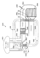
図1は、本発明の排気システムの基本的な一実施形態の構成を模式的に表した構成図である。 FIG. 1 is a configuration diagram schematically showing the configuration of a basic embodiment of the exhaust system of the present invention.
図1に示す排気システム1000は、燃料を燃焼させることで動力を生成するとともに排気ガスを発生する動力装置1001に接続されている。こうした動力装置1001の例としては、軽油を燃料とするディーゼルエンジンや、ガソリンを燃料とするガソリンエンジンを挙げることができる。また、これらのエンジン以外にも、LPG(液化石油ガス)や天然ガスやエタノール、さらにはこれらの燃料の精製物・加工物を燃料とする動力装置を挙げることもできる。
The
動力装置1001が燃料の燃焼時に発生する排気ガスには、環境に有害な成分が含まれている。こうした有害な成分の例としては、環境に有害な窒素酸化物を挙げることができる。また、窒素酸化物以外に一酸化炭素や炭化水素を挙げることもでき、これらも環境に有害な化学物質である。
The exhaust gas generated when the
排気システム1000は、このような有害な成分を排気ガスから除去した上で大気中に排出する役割を担っている。排気システム1000は、排気管1004、還流管1002、浄化ユニット1005、および加熱装置100により構成されている。
The
排気管1004は、動力装置1001に接続され、動力装置1001で発生した排気ガスの、大気中への排気路を形成する管である。
The
還流管1002は、この排気路上で排気管1004に接続され、排気管1004を通る排気ガスの一部を分流して燃焼用の吸気ガスの一部として動力装置1001に還流するための還流路を形成する管である。ここで、動力装置1001から排出される全排気ガスのうち、動力装置1001に還流させる排気ガスの量は、弁1003によって調節される。図1では、動力装置1001で発生し排気管1004を通って大気中に排出される排気ガスの流れと、排気管1004から分流して還流管1002を通って動力装置1001に還流し燃焼用の吸気ガスの一部となる排気ガスの流れとの双方が、太線矢印で示されている。ここで、燃焼用の吸気ガスは酸素を含む気体であり、典型的には大気中の空気をその主な成分として用いることができる。大気中の空気等に一部の排気ガスが混入した吸気ガスでは、排気ガスが全く混入しない場合よりも吸気ガス中の酸素濃度が相対的に低いため、燃料は緩やかに燃焼して燃焼時の温度が上がりにくくなる。さらには、この一部の排気ガスが混入することで、酸素よりも暖まりにくい二酸化炭素の濃度が、排気ガスが全く混入しない場合よりも相対的に高くなるため、このことによっても燃焼時の温度が上がりにくくなる。一般に、燃焼時の温度が高いと窒素酸化物が生成されやすく、排気システム1000では、一部の排気ガスが吸気ガスの一部として動力装置1001に還流することで、窒素酸化物の発生が抑えられている。このように、一部の排気ガスを吸気ガスの一部として動力装置1001に戻して窒素酸化物の発生を抑える方式は、EGR(Exhaust Gas Recirculation)と呼ばれている。
The
浄化ユニット1005は、還流管1002に分流されずに排気管1004を通って流入してきた排気ガスを浄化するものであり、排気ガスの排気路上に設けられている。浄化ユニット1005は、加熱されることで排気ガス浄化能力が活性化する触媒を有しており、上記の排気ガスの浄化は、この触媒を用いて行われる。ここでいう排気ガスの浄化とは、排気ガス中に含まれる、窒素酸化物等といった有害な成分を除去することを指しており、触媒を用いて有害成分に化学反応(たとえば還元や酸化)を起こさせて比較的無害な別の成分に変化させることで有害な成分が除去される。このような触媒としては、たとえば、ディーゼルエンジンの排気ガスの浄化触媒については、アンモニアを還元剤として窒素酸化物の還元反応を促進するSCR(Selective Catalytic Reduction)触媒を挙げることができる。具体的には、バナジウム、モリブデン、タングステン等の酸化物やゼオライト等を用いたSCR触媒を挙げることができる。また、ガソリンエンジンの排気ガスの浄化触媒については、白金やパラジウムやロジウムといった白金族元素を用いる三元触媒を挙げることができる。浄化ユニット1005の構成としては従来から知られている構成(たとえば特許文献1参照)を採用できる。たとえば、複数のセルを有する金属製あるいはセラミック製のハニカム構造体のセル内壁面上に上述の触媒を配置した構成を採用することができる。
The
なお、図1では不図示であるが、浄化ユニット1005よりも排気方向上流側の排気路上に、排気ガス中に含まれる微粒子等を取り除くフィルタ装置が設けられていてもよい(たとえば後述の図5参照)。フィルタ装置は、吸着等により物理的に微粒子を捕集するものであって、浄化の仕組みは浄化ユニット1005とは異なるが、排気ガス中の微粒子も環境に有害な物質であり、微粒子が除去されることで排気ガスの浄化が一層進むこととなる。ただし、排気ガス中に含まれる微粒子の量がそれほど多くない場合には、こうしたフィルタ装置は必ずしも必要ではない。また、図1では不図示であるが、浄化ユニット1005よりも排気方向上流側の排気路上に、浄化ユニット1005と同様の浄化機能を有する別体の浄化ユニットがいくつか設けられていてもよい(たとえば後述の図6参照)。ただし、以下の説明では、こうした別体の浄化ユニットが設けられている場合には、こうした別体の浄化ユニットに流入する排気ガスの温度は十分に高く、こうした別体の浄化ユニットの浄化能力は十分に発揮されるものとする。
Although not shown in FIG. 1, a filter device for removing particulates and the like contained in the exhaust gas may be provided on the exhaust path upstream of the
加熱装置100は、浄化ユニット1005に流入する前の排気ガスを加熱することで、浄化ユニット1005が有する触媒を加熱して触媒の排気ガス浄化能力を活性化するものであり、音波発生部100A、伝播管100C、および熱伝達部100Bを備えている。
The
音波発生部100Aは、還流管1002を通って還流する排気ガスから熱を吸収してその熱を、振動することで音波を伝搬する性質を持つ作動流体に与えて振動させることで、音波を発生するものであり、還流管1002に結合している。
The sound
作動流体としては、少なくとも動力装置1001の周囲の温度帯域において気体状となっているものを採用することができる。その理由は、一般に気体は低粘性で流動性が高く十分な音波伝搬機能が発揮されるからである。気体の種類は特に限定されず、たとえば、大気中の空気を採用することもできる。ただし、反応性が高い気体は化学変化を起こして音波伝搬媒体としての機能が損なわれやすいので、反応性が低い気体が好ましい。また、粘性による音波エネルギーの減衰を避けるため、粘性の低いことが好ましい。たとえば希ガスは、反応性が特に低く、粘性が低いことから作動流体として特に好ましい。
As the working fluid, one that is gaseous at least in a temperature zone around the
伝播管100Cは、音波発生部100Aに接続され、音波発生部100Aで発生した音波を、作動流体の振動によって伝播する管である。伝播管100Cは、後述の熱伝達部100Bにも接続されており、このため、伝播管100Cを通って音波は、音波発生部100Aから熱伝達部100Bに伝播する。
The
ここで、図1では、伝播管100Cとして、図の下側の第1部分101Cと、図の上側の第2部分102Cとの2つの部分で構成された全体でループ状の管が示されている。音波発生部100Aから熱伝達部100Bに音波を伝播するという上述の伝播管100Cの機能は、図の下側の第1部分101Cによって担われており、第2部分102Cは、熱伝達部100Bを通過した音波を音波発生部100Aまで伝播する役割を果たす。このような形態の伝播管100Cでは、同一の作動流体(たとえば特定の種類の作動流体)を繰り返し音波伝搬媒体として使用することができる。図では、このように循環する作動流体の流れが実線矢印で示されている。ただし、作動流体として周囲の空気を用いる場合には、周囲の空気を取り込んでそのまま作動流体として使用できることから、伝播管100Cとしては、図の下側の第1部分101Cのみでよく、図の上側の第2部分102Cは必ずしも必要ではない。
Here, in FIG. 1, as a
熱伝達部100Bは、上述したように伝播管100Cに接続しており、さらに、浄化ユニット1005よりも排気路上の排気方向上流側の位置および浄化ユニット1005よりも排気方向下流側の位置の双方の位置で排気管1004に結合している。この熱伝達部100Bは、伝播管100Cにより伝播されて来た音波を用いて、上記の下流側の位置を通過する排気管1004中の排気ガスの熱を、上記の上流側の位置を通過する排気管1004中の排気ガスに伝達する役割を果たす。
As described above, the
以上説明したように、図1の排気システム1000では、還流管1002の熱に基づき、音波発生部100Aによって音波が発生する。そして、その音波を用いて、浄化ユニット1005の排気方向下流側の排気ガスの熱が、熱伝達部100Bによって浄化ユニットの排気方向上流側の排気ガスに伝達され、排気方向上流側の排気ガスが加熱される。ここで、音波発生部100Aにおける音波発生は、いわゆる熱音響効果による、熱から音波エネルギーへの変換を利用するものであり、熱伝達部100Bにおける熱伝達は、その逆変換(音波エネルギーから熱への変換)を利用するものである。このように排気システム1000では、還流管1002中の排気ガスの熱をエネルギー源として、熱・音響効果により、浄化ユニット1005の下流側から上流側への排気管1004中の排気ガスの熱の汲み上げによる触媒の加熱が行われている。浄化ユニット1005の触媒を加熱する排気管1004中の排気ガスとは異なり、還流管1002中の排気ガスは高温であることは要求されず、むしろ、動力装置1001の燃焼温度を下げる観点から考えると低温である方が好ましい。排気システム1000では、有用性の低い還流管1002中の排気ガスの熱を有効活用して触媒の加熱が行われており、省エネルギー化を実現しつつ触媒の活性状態が維持されている。
As described above, in the
ここで、熱音響効果の詳細に言及しつつ、図1の音波発生部100Aおよび熱伝達部100Bについて詳しく説明する。
Here, the sound
音波発生部100Aは、第1の熱・音波変換部品1A、高温側熱交換器2A、および低温側熱交換器3Aを備えている。第1の熱・音波変換部品1Aには、第1の熱・音波変換部品1Aの2つの端面の間に延びる複数のセル(後述)が形成されており、複数のセルは、内部が上述の作動流体によって満たされ伝播管100Cと連通している。高温側熱交換器2Aおよび低温側熱交換器3Aは、第1の熱・音波変換部品1Aを間に置いて、第1の熱・音波変換部品1Aの両端面にそれぞれ近接して設けられている。ここで、高温側熱交換器2Aは、還流管1002と結合しており、還流管1002中を流れる排気ガスから熱を吸収してその熱を、高温側熱交換器2Aが近接している第1の熱・音波変換部品1Aの端面に供給する熱交換器である。一方、低温側熱交換器3Aは、低温側熱交換器3Aが近接している第1の熱・音波変換部品1Aの端面から熱を吸収して所定の冷却媒体に渡す熱交換器である。所定の冷却媒体としては、たとえば、図1に示すように、低温側熱交換器3Aに結合している冷却管1006を流れる(その流れについては図中の点線矢印参照)、還流管1002中の排気ガスよりは相対的に低温の液体や気体を用いることができる。所定の冷却媒体の具体例としては常温の冷却水を挙げることができる。なお、所定の冷却媒体としては大気中の空気を用いることもでき、この場合、低温側熱交換器3Aを経由して、第1の熱・音波変換部品1Aの低温側熱交換器3A側の端面から熱が大気中に放出されることとなる。大気中の空気を用いる場合には、常温の冷却水を用いる場合と比べると、第1の熱・音波変換部品1Aの低温側熱交換器3A側の端面からの熱の吸収能力(この端面を冷却する能力)は低くなる。その一方で、冷却管1006や、冷却管1006に冷却水を流す手段が不要となるという利点がある。
The sound
上述した高温側熱交換器2Aおよび低温側熱交換器3Aの働きにより、第1の熱・音波変換部品1Aの両端面の間には、高温側熱交換器2A側の端面の方が、低温側熱交換器3A側の端面よりも相対的に高温という温度差が生じる。このような温度差が存在することにより、第1の熱・音波変換部品1Aの複数のセル内の作動流体は、セルの延びる方向に振動を開始し、その振動は音波として第1の熱・音波変換部品1Aから外部に伝播していく。このように温度差を与えると作動流体が振動する現象は、自励振動と呼ばれており、細い管に温度勾配を与えたときに起きる従来からよく知られた現象である。熱音響効果とは、熱に起因するこうした作動流体の自励振動により音波が発生することを指している。ここで、この自励振動について簡単に説明する(なお、詳細については、数多くの文献で説明されているが、たとえば、特開2012−237295号公報でも詳しく説明されている)。
Due to the functions of the high temperature
一般に、細い管に温度勾配が与えられると、高温側では、細い管の内部の作動流体は、管の壁面から熱を吸収して高温側から低温側へ向けて膨張する。そして、その低温側で壁面に対し熱を放出して収縮して元の高温側の方に戻る。このような壁面との熱の授受と膨張圧縮が繰り返されることで、結果的に、作動流体が管の延在方向(管が延びる方向)に振動することとなる。簡単にいえば、この作動流体の動きは、壁の壁面の温度勾配を緩和する(弱める)ように、熱を運ぶ作動流体の動きだということができる。この説明からも明らかであるが、この現象は、管が細いために内部の作動流体に対する壁面の熱的影響が大きい場合にのみ生じるものである。このため、管を太くしていくと壁面の熱的影響が小さくなっていき(すなわち断熱状態に近づき)、こうした自励振動は生じにくくなる。そこで、自励振動により音波を発生させる上では、管の太さが重要な要素となり、この管の太さは、より定量的には、管の断面の面積をS、この断面の周長をCとしたときにHD=4×S/Cで定義される水力直径HDによって評価できる。 Generally, when a temperature gradient is applied to the thin tube, on the high temperature side, the working fluid inside the thin tube absorbs heat from the wall of the tube and expands from the high temperature side to the low temperature side. Then, on the low temperature side, heat is released to the wall surface to shrink and return to the original high temperature side. The repetition of heat exchange with such a wall and expansion and compression results in the working fluid vibrating in the direction in which the pipe extends (the direction in which the pipe extends). Simply stated, this movement of the working fluid can be said to be the movement of the working fluid carrying heat so as to relieve (weaken) the temperature gradient of the wall of the wall. As is apparent from this explanation, this phenomenon occurs only when the thermal effect of the wall on the working fluid inside is large because the pipe is thin. For this reason, as the tube is made thicker, the thermal influence of the wall becomes smaller (that is, it becomes closer to the adiabatic state), and such self-excited vibration becomes difficult to occur. Therefore, the thickness of the pipe is an important factor in generating sound waves by self-excited vibration, and the thickness of the pipe more quantitatively determines the area of the cross section of the pipe S, and the circumferential length of this cross section It can be evaluated by the hydraulic diameter HD defined by HD = 4 × S / C when it is C.
上述の第1の熱・音波変換部品1Aにおける複数のセルは、自励振動が生じるような十分に小さい水力直径HDを有しており、第1の熱・音波変換部品1Aの両端面における上述の温度差により自励振動が生じる。この自励振動により、高温側である高温側熱交換器2A側の端面から低温側である低温側熱交換器3A側に進行する音波が発生する。低温側熱交換器3Aは伝播管100Cの第1部分101Cの一方の端部と接続されており、発生した音波は、熱伝達部100Bに向かって伝播管100Cの第1部分101C内を進行する。
The plurality of cells in the first heat /
熱伝達部100Bは、第2の熱・音波変換部品1B、上流側熱交換器2B、および下流側熱交換器3Bを備えている。第2の熱・音波変換部品1Bの構成としては、上述の第1の熱・音波変換部品1Aと同様の構成(両端面間に複数のセルが延びている構成)を採用できる。上流側熱交換器2Bおよび下流側熱交換器3Bは、第2の熱・音波変換部品1Bを間に置いて、第2の熱・音波変換部品1Bの両端面にそれぞれ近接して設けられている。ここで、下流側熱交換器3Bは、伝播管100Cの第1部分101Cの、上述の低温側熱交換器3Aとは反対側の端部と接続されており、さらに、浄化ユニット1005の排気方向下流側の位置で排気管1004に結合している。一方、上流側熱交換器2Bは、浄化ユニット1005の排気方向上流側の位置で排気管1004に結合している。結合相手が異なることを除き、上流側熱交換器2Bおよび下流側熱交換器3Bとしては、高温側熱交換器2Aおよび低温側熱交換器3Aと同じ構成のものをそれぞれ採用することができる。
The
第1部分101C内を進行してきた音波を受けた熱伝達部100Bでは、上述した熱音響効果のメカニズム(温度勾配に起因して音波が発生)とは逆のメカニズム(音波に起因して温度勾配が発生)により、第2の熱・音波変換部品1Bの両端面間に温度差が生じる。より具体的にいえば、第2の熱・音波変換部品1Bの上流側熱交換器2B側の端面が、第2の熱・音波変換部品1Bの下流側熱交換器3B側の端面よりも相対的に高温となる。この温度差は、第2の熱・音波変換部品1Bの複数のセル内を通る音波が、第2の熱・音波変換部品1Bの下流側熱交換器3B側の端面から上流側熱交換器2B側の端面に熱を運ぶことによって生じるものである。このとき、下流側熱交換器3Bは、下流側熱交換器3Bが排気管1004に結合している位置(浄化ユニット1005の排気方向下流側の位置)を通過する排気管1004中の排気ガスから熱を吸収して、第2の熱・音波変換部品1Bの下流側熱交換器3B側の端面にその熱を供給する。一方、上流側熱交換器2Bは、第2の熱・音波変換部品1Bの上流側熱交換器2B側の端面から熱を吸収して、上流側熱交換器2Bが排気管1004に結合している位置(浄化ユニット1005の排気方向上流側の位置)を通過する排気管1004中の排気ガスに供給する。この結果、浄化ユニット1005に流入する前の排気ガスの加熱が行われることとなる。
In the
以下、音波発生部100Aおよび熱伝達部100Bの構成について一具体例を挙げてさらに詳しく説明する。上述したように、音波発生部100Aおよび熱伝達部100Bは、熱の授受のための結合相手(還流管1002や排気管1004や冷却管1006)が異なる点を除き、同じ構成のものを採用することができる。そこで、以下では、音波発生部100Aを例にとってその構成の一具体例を説明する。
Hereinafter, the configuration of the
図2は、図1の音波発生部100Aの構成の一具体例を表した模式図である。
FIG. 2 is a schematic view showing one specific example of the configuration of the
以下では、図1の音波発生部100Aの構成の一具体例について説明するが、図1の構成要素と対応する構成要素については同一の符号を用いて説明する。なお、上述したように、図1の熱伝達部100Bは、音波発生部100Aと同じ構成を取り得るため、以下に説明する音波発生部100Aの構成の具体例は、熱伝達部100Bの構成の具体例にもなっている。
Hereinafter, although a specific example of the configuration of the
図2の音波発生部100Aは、図1の説明で上述したように、第1の熱・音波変換部品1A、高温側熱交換器2Aおよび低温側熱交換器3Aを備えており、さらにこれらの構成要素に加えて、金属部材31および干渉材12も備えている。
The
図2の第1の熱・音波変換部品1Aは、それぞれが細い管状の貫通孔である複数のセル14が、隔壁11によって区画形成されてなるハニカム構造体である。ここで、本明細書では、「セル」という語を、隔壁を含まない貫通孔のみを指すものとして用いる。各セル14は、図2の垂直方向(上下方向)に延びており、以下では、各セル14が延びている方向を各セル14の延在方向と呼ぶ。各セル14は、低温側熱交換器3A側の端面および高温側熱交換器2A側の端面の両端面において開口する。第1の熱・音波変換部品1Aの、低温側熱交換器3A側の端面は、金属部材31と接しているとともに、金属部材31を間において低温側熱交換器3Aに対向している。ここで、後述するように金属部材31は熱伝導を担うものなので、金属部材31の材質としては熱伝導率の高いものが好ましく、たとえば、銅製のものを用いることができる。なお、本発明では、金属部材31が省略された形態も採用可能であるが、この場合、第1の熱・音波変換部品1Aと低温側熱交換器3Aとの間の隙間は極力小さいことが好ましい。
The first heat /
金属部材31は、中央部に互いに平行な複数本のスリット(不図示)が形成された板状の金属製部材であり、図2では、その板状の側面部(厚みの部分)のみが図示されている。
The
図2の低温側熱交換器3Aは、複数枚の金属製(たとえば銅製)メッシュ板を重ね合わせてなるメッシュ積層体30を有している。低温側熱交換器3Aが結合している冷却管1006から流入してきた冷却媒体は、メッシュ積層体30の周囲を取り巻くように流れる(図2の点線矢印参照)。第1の熱・音波変換部品1Aの低温側熱交換器3A側の端面から金属部材31を介してメッシュ積層体30に伝わった熱は、この冷却媒体に伝わりこの冷却媒体によって運ばれていく。この結果、第1の熱・音波変換部品1Aの低温側熱交換器3A側の端面は低い温度に保たれる。なお、このような低温側熱交換器3Aと冷却管1006中の冷却媒体との間の熱の授受の機構は、後述する、高温側熱交換器2Aと還流管1002中の排気ガスとの間の熱の授受の機構(後述の図3参照)と、熱が授受される向きが逆となることを除き同じである。
The low temperature
図2の第1の熱・音波変換部品1Aの側面は、干渉材12によって取り巻かれており、図2の模式的な断面図では、その取り巻く干渉材12が、第1の熱・音波変換部品1Aを図の左右両側から挟み込む2つに分かれた干渉材12として示されている。この干渉材12は、第1の熱・音波変換部品1Aの両端面の間に広がる第1の熱・音波変換部品1Aの側面と第1の熱・音波変換部品1A外部の周囲環境との間で熱の授受が行われるのを抑える断熱材としての役割を果たしている。
The side surface of the first heat /
図2の高温側熱交換器2Aは、熱交換ハニカム構造体20を備えている。熱交換ハニカム構造体20は、柱状のハニカム構造体であり、熱交換ハニカム構造体20では、それぞれが図2の垂直方向(上下方向)に延びた2以上のセル24が、隔壁21によって区画形成されている。これら2以上のセル24は、伝播管100Cおよび第1の熱・音波変換部品1Aの複数のセル14と連通しており、作動流体で満たされている。ただし、第1の熱・音波変換部品1Aとは異なり、これら2以上のセル24それぞれの水力直径は十分に大きく、熱交換ハニカム構造体20では自励発振はほとんど無視できる。図2に示すように、熱交換ハニカム構造体20は、第1の熱・音波変換部品1Aの端面(高温側熱交換器2A側の端面)と近接しており、還流管1002を流れる排気ガスから熱を受け取ってその熱をこの端面(高温側熱交換器2A側の端面)に伝達する。この熱伝達により、第1の熱・音波変換部品1Aの高温側熱交換器2A側の端面が高温状態(低温側熱交換器3A側の端面の温度より高い状態)に維持される。
The high temperature side heat exchanger 2 </ b> A of FIG. 2 includes a heat
この熱伝達という役割を果たす上で、熱交換ハニカム構造体20の材料としては熱伝導率の高いものが好ましく、金属材料、たとえば銅を用いることができる。さらには、このようにハニカム構造を有する部材に代えて、複数枚の金属製(たとえば銅製)メッシュ板を重ね合わせてなるメッシュ積層体の構造を有する部材が採用されてもよい。ただし、こうした金属材料からなる熱交換ハニカム構造体20(あるいはメッシュ積層体)が、高温下で作動流体と反応して変質することを防ぐ観点から、このときの作動流体としては、希ガス等のように金属材料との反応性の低いものを採用することが好ましい。なお、使用環境である高温の条件下でも高い熱伝導率を維持するSiC(炭化珪素)を主成分とするセラミックス材料を熱交換ハニカム構造体20(あるいはメッシュ積層体)の材料として採用することができる。なお、ここでいう「主成分」とは、全構成材料中50質量%以上を占める成分を指している。SiC(炭化珪素)は金属ではないが、高温耐久性があるセラミックス材料の中でも比較的熱伝導率が高く、さらに、一般的な金属材料(鉄・銅等)に比べると反応性が相対的に低い材料である。SiCを主成分とするセラミックス材料としては、具体的には、単純なSiCに加え、Si含浸SiC、(Si+Al)含浸SiC、金属複合SiC、再結晶SiC、Si3N4、及びSiC等を採用することができる。これらの中でも、Si含浸SiC、(Si+Al)含浸SiCが好ましい。その理由は、Siを含浸するSiCは、高い熱伝導率および耐熱性を有することに加え、多孔質体であっても気孔率が低く緻密に形成されているため、Siを含浸しないSiCに比して相対的に高い強度を実現できるからである。
In order to play the role of heat transfer, a material having a high thermal conductivity is preferable as a material of the heat
ここで、熱交換ハニカム構造体20は、伝播管100Cと接続されることで、上述の熱伝達という役割以外に、音波の進行経路の一部という役割も担っている。すなわち、図1の熱伝達部100Bを通過し伝播管100Cの第2部分102C(図1参照)中を進行する音波は、高温側熱交換器2Aに到達し熱交換ハニカム構造体20における2以上のセル24内を進行することとなる。
Here, since the heat
図3は、図2のAA線に沿った高温側熱交換器2Aの断面図である。
FIG. 3 is a cross-sectional view of the high temperature
図3に示すように、高温側熱交換器2Aでは、熱交換器筐体22で取り囲まれた中央に熱交換ハニカム構造体20が嵌め込まれた構成となっている。この高温側熱交換器2Aには、図3の太線矢印で示すように、図3の右側の還流管1002から排気ガスが流入し、図3の左側の還流管1002中へ流出していく。このとき、流入してきた排気ガスは、熱交換ハニカム構造体20の円形の外周を構成する外周壁23に直接に突き当たり、熱交換ハニカム構造体20周囲の太線矢印で示すように、外周壁23の上下二手に分かれて外周壁23に沿って進む。この2つの排気ガスの流れは、外周壁23に沿って熱交換ハニカム構造体20周囲の上半分あるいは下半分に沿って熱交換ハニカム構造体20の周囲をほぼ半周したところで合流し、図3の左側の還流管1002中へ流出していく。このように熱交換ハニカム構造体20の外周壁23に対して直接に高温の加熱流体が接触しながら移動することで、排気ガスから外周壁23に対して多量の熱が伝達され、その熱は、熱交換ハニカム構造体20内部の隔壁21やセル24内部の作動流体にも伝達される。この伝達された熱が、図2の第1の熱・音波変換部品1Aの高温側熱交換器2A側の端面に供給される。
As shown in FIG. 3, in the high temperature side heat exchanger 2 </ b> A, the heat
なお、以上では、熱交換ハニカム構造体20(あるいは熱交換ハニカム構造体20の外周壁23)が直接に排気ガスと接触する形態について説明したが、本発明では、外周壁23の周囲を金属で覆う形態も採用することができる。外周壁23の周囲を覆う金属が追加されると排気ガスから熱交換ハニカム構造体20への熱の吸収量が多少減じるが、熱交換ハニカム構造体20が強固に保護されることとなる。この結果、熱交換ハニカム構造体20の破損や熱交換ハニカム構造体20内部の作動流体が外部に漏れて排気ガスに混入するのが効果的に抑制される。
Although the heat exchange honeycomb structure 20 (or the outer
また、図3に示す具体例では、還流管1002中の排気ガスの流路と熱交換ハニカム構造体20中の作動流体の流路とが交差した形態で熱の交換が行われる、いわゆるクロスフロー型の熱交換器について説明されている。しかし、本発明では、このようなクロスフロー型の熱交換器に代えて、排気ガスの流路と熱交換ハニカム構造体20中の作動流体の流路とが熱交換器において互いに平行となった形態で熱の交換が行われる、いわゆるカウンターフロー型の熱交換器が採用されてもよい。一般に、カウンターフロー型の熱交換器に比べるとクロスフロー型の熱交換器の方が、熱交換器を排気システムに組み込むのが容易であり、設計上は有利である。しかし、熱交換効率の点では、カウンターフロー型の熱交換器の方がクロスフロー型の熱交換器よりも一般に高く、熱交換効率の点では、カウンターフロー型の熱交換器の方が有利である。
Further, in the specific example shown in FIG. 3, so-called cross flow in which heat exchange is performed in a form in which the flow path of the exhaust gas in the
次に、図2の第1の熱・音波変換部品1Aについて詳しく説明する。
Next, the first heat /
図4は、図2に示す第1の熱・音波変換部品1Aのセル14の延在方向に垂直な面内における第1の熱・音波変換部品1Aの断面図である。
FIG. 4 is a cross-sectional view of the first heat /
図4に示すように、第1の熱・音波変換部品1Aは、それぞれが細い管状の貫通孔である複数のセル14が、隔壁11によって区画形成され、さらにそれら隔壁11の全体の外周を外周壁13(図2では図示が省略されている)で取り囲むことで形成されている。ここで、外周壁13の構成材料としては、隔壁11の構成材料と同じものを採用できる。
As shown in FIG. 4, in the first heat /
上述したように、自励振動により音波を発生させる上でセル14の水力直径HDが1つの重要な要素であり、第1の熱・音波変換部品1Aのセル14の水力直径HDは0.4mm以下のきわめて小さい値となっていることが好ましい。このような水力直径HDがきわめて小さいセルが形成されていることで、第1の熱・音波変換部品1Aでは、十分な熱音響効果を得ることができる。逆に、水力直径HDが0.4mmより大きい場合、小さい熱音響効果しか得られないことがある。
As described above, the hydraulic diameter HD of the
ここで、より大きな熱音響効果を発揮するには、上述の水力直径HDが小さいセルを、できるだけ数多く形成するのが有利である。言い換えれば、第1の熱・音波変換部品1Aの端面における開口率が大きい方が有利である。第1の熱・音波変換部品1Aが各端面において60%以上の高い開口率を有していることが好ましく、これにより大きな熱音響効果を発揮することができる。逆に60%未満の開口率では、熱音響効果に寄与するセルが少なすぎてあまり大きな熱音響効果は得られないことがある。
Here, in order to exert a larger thermoacoustic effect, it is advantageous to form as many cells as possible with the above-described hydraulic diameter HD. In other words, it is advantageous that the aperture ratio at the end face of the first heat /
ただし、開口率が高すぎると、第1の熱・音波変換部品1Aの空洞部分が多すぎることとなり、第1の熱・音波変換部品1A全体の耐久性や強度が低下することがある。そこで、第1の熱・音波変換部品1Aでは開口率は93%以下に抑えられていることが好ましい。実際、開口率が93%を超えると、発生した音波による衝撃や第1の熱・音波変換部品1Aの両端の温度差に起因する熱的な歪みやねじれ(熱応力)により生じる第1の熱・音波変換部品1Aの損傷が無視できなくなることがある。
However, if the aperture ratio is too high, the number of hollow portions of the first heat /
まとめると、第1の熱・音波変換部品1Aでは、第1の熱・音波変換部品1Aの端面における開口率が60%以上93%以下となることが、十分な熱音響効果の発揮と十分な耐久性・強度との適度なバランスを実現する観点から好ましい。なお、60%以上93%以下の開口率の中でも、80%以上93%以下の開口率がさらに好ましい。
In summary, in the first heat /
なお、上記開口率は、延在方向に垂直な断面を顕微鏡で撮影し、このときの断面の撮影画像から、材料部分面積S1と空隙部分面積S2を求め、S1とS2を用いてS2/(S1+S2)として求められる。 For the aperture ratio, a cross section perpendicular to the extending direction is photographed with a microscope, and from the photographed image of the cross section at this time, the material partial area S1 and the void partial area S2 are determined, and S2 / (S2 / S2) It is calculated as S1 + S2).
また、第1の熱・音波変換部品1Aでは、セル14の延在方向に垂直な前記セルの断面形状は、角部が弯曲した多角形の形状であり、その形状の角部における曲率半径が0.02mm以上0.1mm以下であることが好ましい。図4では、セル14の形状の例としては、角部が弯曲した三角形の形状が図の右上の拡大図に示されており、この角部の曲率半径は0.02mm以上0.1mm以下となっている。曲率半径が0.02mm以上であることでその緩やかに弯曲した形状により、セル14を押しつぶすように働く衝撃に対し十分に対抗できる。これは、トンネル等の穴の形状としては、丸みを帯びた形状の方が角ばった形状よりも、周囲からの外力に対抗しやすいのと同様の理由に基づくものである。ただし、弯曲部分が大きすぎると、今度は、各セルの角部付近で隔壁11が分厚くなって開口率が減少し、得られる熱音響効果が小さくなる。そこで、曲率半径が0.1mm以下となっていることで、同時に高い熱音響効果も維持されている。
In the first heat /
なお、セル14の角部における曲率半径については、セル14の延在方向に垂直な断面の拡大写真をとり、そのセル14の断面形状に基づき測定することができる。
The radius of curvature at the corner of the
セル14の延在方向に垂直な面内でのセル14の形状としては、三角形、四角形、五角形、六角形等の様々な多角形、および、楕円形(真円の形状含む)を採用できるが、三角形、四角形、六角形、およびこれらの組み合わせが好ましく、図4の第1の熱・音波変換部品1Aの右上のセル14の拡大図のように、三角形のセル14が特に好ましい。三角形のセル14が特に好ましいのは、様々な多角形および楕円形のセル形状のうち、三角形のセル形状が、隔壁の厚さをできるだけ薄くして数多くのセルを配列させるのに最も適しているからである。ここで、自動車の排気ガスから微粒子を取り除くフィルタ用のハニカム構造体では、セルの角部が鋭角であると、微粒子が角部に堆積しやすいといった問題があるため、三角形のセル形状は、(原理的には採用可能であっても)実際上、採用されないことが多い。しかし、熱音響効果を発揮するハニカム構造体としては、自励振動を起こす作動流体(希ガス等の気体)に関して、このような問題は存在しないため、数多くのセルを配列させるのに最も適した三角形(ただし角部が弯曲した三角形)のセル形状を積極的に活用できる。
The shape of the
また、第1の熱・音波変換部品1Aでは、その両端面の間の長さをLとしたときに、この長さLに対する上述の水力直径HDの比HD/Lが0.005以上0.02未満となっている。仮に、HD/Lが0.005未満であると、水力直径HDに比して第1の熱・音波変換部品1Aが長すぎて、第1の熱・音波変換部品1Aの各セル内の作動流体が熱・音波変換部品両端の温度差の影響を受けにくくなる。この場合、各セル内の作動流体と隔壁11との間における熱の授受が不十分で十分な熱音響効果が得られない。一方、仮に、HD/Lが0.02以上であると、今度は、水力直径HDに比して第1の熱・音波変換部品1Aが短すぎて、各セル内の作動流体と隔壁11との間で熱の授受が不十分なまま第1の熱・音波変換部品1Aにおいて高温側熱交換器2A側から低温側熱交換器3A側に隔壁11を熱が伝導していくことになる。この結果、やはり十分な熱音響効果が得られない。そこで、第1の熱・音波変換部品1Aでは、比HD/Lが0.005以上0.02未満となるよう工夫されており、このため、各セル内の作動流体と隔壁11との間における熱の授受が十分に行われる。この結果、第1の熱・音波変換部品1Aでは、十分な熱音響効果を得ることができる。
In the first heat /
また、第1の熱・音波変換部品1Aでは、第1の熱・音波変換部品1Aの構成材料、特に、隔壁11の構成材料の20〜800℃における熱膨張率が6ppm/K以下であることが好ましい。このように熱膨張率が低い状態を実現するための1つの方法としては、セラミックス材料の中でも熱膨張率が低いコージェライト製のハニカム構造体を採用することが考えられる。ここで、「コージェライト製のハニカム構造体」とは、ハニカム構造体を作製するためのセラミック原料として、シリカが42〜56質量%、アルミナが30〜45質量%、マグネシアが12〜16質量%の範囲に入る化学組成となるように配合され、焼成されるとコージェライトになるコージェライト化原料を用いて作製されたハニカム構造体を指している。
Further, in the first heat /
熱膨張率の測定方法としては、たとえば、各セルの延在方向に沿った10mm以上の長さを有する試験片であって、この延在方向、および、この延在方向に直交する方向を含む断面の面積が4mm2以上100mm2以下である試験片を第1の熱・音波変換部品1Aから切り出し、この試験片の延在方向の熱膨張率を、石英を標準比較サンプルとする示差式の熱膨張計により測定する方法を採用することができる。
As a method of measuring the thermal expansion coefficient, for example, a test piece having a length of 10 mm or more along the extending direction of each cell, including the extending direction and a direction orthogonal to the extending direction A test piece having a cross-sectional area of 4 mm 2 or more and 100 mm 2 or less is cut out from the first heat /
隔壁11の構成材料の、20〜800℃における熱膨張率が6ppm/K以下となることで、両端部に温度差が生じたときの第1の熱・音波変換部品1Aの損傷が抑えられる。なお、6ppm/K以下の熱膨張率の中でも、4ppm/K以下の熱膨張率であることがさらに好ましい。
When the thermal expansion coefficient at 20 to 800 ° C. of the constituent material of the
以上が、図2の音波発生部100Aの構成の具体例な説明である。なお、上述したように、以上の音波発生部100Aの構成の具体例は、熱伝達部100Bの構成の具体例にもなっている。
The above is the specific description of the configuration of the
次に、図1の動力装置1001の具体例を挙げつつ、図1の排気システムの具体例について説明する。
Next, a specific example of the exhaust system of FIG. 1 will be described while giving a specific example of the
図5は、図1の動力装置1001としてディーゼルエンジンを用いた場合における、図1の排気システム1000の一具体例を示す模式的な構成図である。
FIG. 5 is a schematic configuration view showing one specific example of the
図5には、図1の排気システム1000の一具体例として、ディーゼルエンジン2001に接続された排気システム2000が示されている。以下、この排気システム2000について説明するが、図1の構成要素と重複する構成要素については同一の符号を付し、その説明については図1における上述の説明を参照することとして重複説明は省略する。
FIG. 5 shows an
図5の排気システム2000は、ディーゼルエンジン2001が動力生成のために軽油を燃焼したときに発生する排気ガスから、微粒子や窒素酸化物等といった環境に有害な物質を除去する役割を担っている。排気システム2000は、図1で説明した加熱装置100に加え、排気管2004、還流管2002、および、DOC(Diesel Oxidation Catalyst)担持体2007を備えている。排気システム2000はさらに、DPF(Diesel Particulate Filter)2008、尿素噴射装置2009、およびSCR触媒コンバータ2005を備えている。ここで、SCR触媒コンバータ2005が、図1の浄化ユニット1005の一具体例に相当する。
The
図5の排気管2004は、ディーゼルエンジン2001に接続され、ディーゼルエンジン2001で発生した排気ガスの、大気中への排気路を形成する管である。図5の還流管2002は、この排気路上で排気管2004に接続され、排気管2004を通る排気ガスの一部を分流して燃焼用の吸気ガスの一部としてディーゼルエンジン2001に還流するための還流路を形成する管である。ここで、ディーゼルエンジン2001から排出される全排気ガスのうち、ディーゼルエンジン2001に還流させる排気ガスの量は、弁2003によって調節される。これら排気管2004、還流管2002、および弁2003の機能は、図1で説明した排気管1004、還流管1002、および弁1003の機能と実質的に同じである。
The
DOC担持体2007は、後述のDPFで捕集される煤等の微粒子(炭素系微粒子)を燃焼(酸化)除去する際に、炭化水素や一酸化炭素の酸化を促進するとともに、一酸化窒素を二酸化窒素に酸化して二酸化窒素の量を相対的に増やす機能を有している。ここで、二酸化窒素の量が一酸化窒素よりも相対的に多いことで、炭素系微粒子の酸化反応が連続的に進みやすくなる。DOC担持体2007としては、従来から知られているものを採用できる。たとえば、炭化水素や一酸化炭素の酸化反応を促進する酸化触媒(典型的には白金やパラジウムといった白金族元素を用いた触媒)を、複数のセルを有するハニカム構造体のセル内壁面に担持させたものを採用することができる。
The
DPF2008は、排気ガス中の煤等の微粒子(炭素系微粒子)を捕集する機能を有している。DPF2008としては、従来から知られているものを採用できる。たとえば、複数のセルを有するセラミック製のハニカム構造体において、各セルの一方の端面における開口を目封止してセル内壁で微粒子(炭素系微粒子)を捕集する方式を用いたものを採用することができる。
The
尿素噴射装置2009は、後述のSCR触媒コンバータ2005に流入する前の排気管2004中の排気ガスに対し、尿素を噴射して混入する装置である。
The
SCR触媒コンバータ2005は、アンモニアを還元剤として窒素酸化物の還元反応を促進するSCR触媒を有しており、排気ガスの排気路上の、尿素噴射装置2009よりも排気方向下流側に設けられている。SCR触媒コンバータ2005は、尿素噴射装置2009から噴射された尿素が高温下で加水分解されることで生成されたアンモニアと、上述のSCR触媒とを用いて、排気ガス中の窒素酸化物を還元し水や窒素を生成する。SCR触媒コンバータ2005としては、従来から知られているものを採用できる。たとえば、複数のセルを有するセラミック製のハニカム構造体において、内壁面に、SCR触媒を担持させたものを採用することができる。SCR触媒としては、バナジウム、モリブデン、タングステン等の酸化物やゼオライト等を用いたSCR触媒を挙げることができる。ここで、SCR触媒による排気ガスの浄化能力は、SCR触媒が加熱されることで活性化する。
The SCR
加熱装置100は、還流管2002に分流されずに排気管2004を流れてくる排気ガスであって、尿素噴射装置2009による尿素の噴射を受ける前の排気ガスを加熱する。すなわち、加熱装置100の熱伝達部100Bが有する上流側熱交換器2Bは、尿素噴射位置よりも排気方向上流側の位置において排気管2004に結合し、この結合位置を通過する排気管2004中の排気ガスに対し熱を供給する(図5参照)。この熱の供給を受けた排気ガスが、(尿素の噴射を受けた上で)SCR触媒コンバータ2005に流れ込むことで、SCR触媒コンバータ2005が有するSCR触媒が加熱されてその排気ガスの浄化能力が活性化する。この形態では、噴射された尿素は、噴射箇所よりも排気方向上流側から流れてくる高温の排気ガスにより十分に蒸発してアンモニアに加水分解され、この結果、アンモニアを還元剤とする窒素酸化物の還元反応が十分に促進される。仮に、尿素噴射装置2009により尿素が噴射された後の排気ガスを加熱する形態が採用されたとすると、加熱前の比較的温度が低い排気ガスでは尿素の蒸発が進みにくいため、窒素酸化物の還元反応がアンモニア不足で十分に起こらないといった事態が生じ得る。
The
図5の排気システム2000では、排気管2004から分流して還流管2002に流れ込む排気ガスの温度は、一般的なディーゼルエンジンの排気システムにおけるディーゼルエンジンからの排気直後の排気ガスの温度である150〜600℃程度である。また、DPF2008を通過した直後の排気ガス(加熱装置100による加熱を受ける前の排気ガス)は、一般的なディーゼルエンジンの排気システムと同様、外気温度〜300℃程度である。一方、SCR触媒が加熱されて十分な浄化能力を発揮する温度は、200℃以上である。加熱装置100は、DPF2008を通過後であって加熱を受ける前の排気ガスを、還流管2002を流れる排気ガスの熱を利用した熱音響効果により、SCR触媒が十分な浄化能力を発揮する上記の温度以上となるように加熱する。
In the
加熱装置100による加熱の原理や加熱の機構は、図1において説明したものと同じであり、ここではその説明を参照することとして重複説明は省略する。ここで、一般に、ディーゼルエンジンを用いた動力システムでは、エンジン等の高温化しやすい装置を水を用いて冷却するための冷却用の水循環機構を備えていることが多い。そこで、図5の加熱装置100の音波発生部100Aでは、低温側熱交換器3Aは、第1の熱・音波変換部品1Aの低温側熱交換器3A側の端面を冷却する(熱を吸収する)のに用いる冷却媒体として、こうした水循環機構が有する冷却管2006中の常温の水を流用している。なお、図5の加熱装置100の一具体例としては、図1の音波発生部100A(および熱伝達部100B)に、図2、図3、および図4で説明した、音波発生部100A(および熱伝達部100B)の具体例を適用した図1の加熱装置100を採用することができる。
The principle of heating by the
次に、図1の動力装置1001のさらに別の具体例を挙げつつ、図1の排気システムのさらに別の一具体例について説明する。
Next, another specific example of the exhaust system of FIG. 1 will be described while giving another specific example of the
図6は、図1の動力装置1001としてガソリンエンジンを用いた場合における、図1の排気システム1000の一具体例を示す模式的な構成図である。
FIG. 6 is a schematic configuration view showing one specific example of the
図6には、図1の排気システム1000の一具体例として、ガソリンエンジン3001に接続された排気システム3000が示されている。以下、この排気システム3000について説明するが、図1の構成要素と重複する構成要素については同一の符号を付し、その説明については図1における上述の説明を参照することとして重複説明は省略する。
FIG. 6 shows an
図6の排気システム3000は、ガソリンエンジン3001が動力生成のためにガソリンを燃焼したときに発生する排気ガスから、窒素酸化物や一酸化炭素や炭化水素(HC)を除去する役割を担っている。排気システム3000は、図1で説明した加熱装置100に加え、排気管3004、還流管3002、第1の三元触媒ユニット3007、および、第2の三元触媒ユニット3005を備えている。ここで、第2の三元触媒ユニット3005が、図1の浄化ユニット1005の一具体例に相当する(後述の各三元触媒ユニットが有する触媒の浄化能力の活性化の説明参照)。
The
図6の排気管3004は、ガソリンエンジン3001に接続され、ガソリンエンジン3001で発生した排気ガスの、大気中への排気路を形成する管である。図6の還流管3002は、この排気路上で排気管3004に接続され、排気管3004を通る排気ガスの一部を分流して燃焼用の吸気ガスの一部としてガソリンエンジン3001に還流するための還流路を形成する管である。ここで、ガソリンエンジン3001から排出される全排気ガスのうち、ガソリンエンジン3001に還流させる排気ガスの量は、弁3003によって調節される。これら排気管3004、還流管3002、および弁3003の機能は、図1で説明した排気管1004、還流管1002、および弁1003の機能と実質的に同じである。
The
第1の三元触媒ユニット3007および第2の三元触媒ユニット3005は、還流管3002に分流されずに排気管3004を流れてくる排気ガスの浄化を行うものであり、この排気ガスの排気路上に設けられている。これら第1の三元触媒ユニット3007および第2の三元触媒ユニット3005は、窒素酸化物や一酸化炭素や炭化水素(HC)といった有害な物質を、窒素や水や二酸化炭素といった相対的に無害な物質に変える化学反応を促進する三元触媒を有している。これら第1の三元触媒ユニット3007および第2の三元触媒ユニット3005としては、従来から知られているものを採用できる。たとえば、複数のセルを有するセラミック製のハニカム構造体において、内壁面に、三元触媒を担持させたものを採用することができる。三元触媒としては、白金やパラジウムやロジウムといった白金族元素を用いたものを採用することができる。ここで、三元触媒による排気ガスの浄化能力は、三元触媒が加熱されることで活性化する。
The first three-
図6の排気システム3000では、排気管3004から分流して還流管3002を流れ込む排気ガスの温度は、一般的なガソリンエンジンの排気システムにおけるガソリンエンジンからの排気直後の排気ガスの温度である100〜1000℃程度である。ここで、第1の三元触媒ユニット3007は、ガソリンエンジン3001の近傍に設けられた、いわゆるガソリンエンジン3001直下の三元触媒ユニットであり、第1の三元触媒ユニット3007に流入してくる排気ガスの温度も100〜1000℃程度である。一方、第2の三元触媒ユニット3005は、第1の三元触媒ユニット3007に比べると、ガソリンエンジン3001から比較的遠い位置に設けられた、いわゆる床下の三元触媒ユニットである。このため、第2の三元触媒ユニット3005に流入してくる排気ガスの温度は、加熱装置100による加熱を受けない限り、第1の三元触媒ユニット3007に流入してくる排気ガスの温度に比べかなり低くなり、外気温度〜500℃程度となる。ここで、三元触媒が加熱されて十分な浄化能力を発揮する温度は400℃以上である。このため、第1の三元触媒ユニット3007については、第1の三元触媒ユニット3007に流入してくる排気ガスを加熱しなくても十分な浄化能力の発揮が期待できる。しかし、第2の三元触媒ユニット3005については、第2の三元触媒ユニット3005に流入してくる排気ガスを加熱しないと十分な浄化能力が発揮されないおそれがある。
In the
そこで、図6の排気システム3000では、加熱装置100が、第1の三元触媒ユニット3007による浄化処理を受けて流出してきた排気ガスであって、第2の三元触媒ユニット3005に流入する前の排気ガスを加熱する。すなわち、加熱装置100の熱伝達部100Bが有する上流側熱交換器2Bは、第1の三元触媒ユニット3007よりも排気方向下流側の位置であって第2の三元触媒ユニット3005よりも排気方向上流側の位置において排気管3004に結合し、この結合位置を通過する排気管3004中の排気ガスに対し熱を供給する(図6参照)。この熱の供給を受けた排気ガスが、第2の三元触媒ユニット3005に流れ込むことで、第2の三元触媒ユニット3005が有する三元触媒が400℃以上の温度に加熱されその排気ガスの浄化能力が十分に発揮される。
Therefore, in the
加熱装置100による加熱の原理や加熱の機構は、図1において説明したものと同じであり、ここではその説明を参照することとして重複説明は省略する。ここで、一般に、ガソリンエンジンを用いた動力システムでは、エンジン等の高温化しやすい装置を、水を用いて冷却するための冷却用の水循環機構を備えていることが多い。そこで、図6の加熱装置100の音波発生部100Aでは、低温側熱交換器3Aは、第1の熱・音波変換部品1Aの低温側熱交換器3A側の端面を冷却する(熱を吸収する)のに用いる冷却媒体として、こうした水循環機構が有する冷却管3006中の常温の水を流用している。なお、図6の加熱装置100の一具体例としては、図1の音波発生部100A(および熱伝達部100B)に、図2、図3、および図4で説明した、音波発生部100A(および熱伝達部100B)の具体例を適用した図1の加熱装置100を採用することができる。
The principle of heating by the
なお、一般に、三元触媒を有する触媒ユニットにおいては、ガソリンエンジンの始動時に排気ガスの温度が低いことが三元触媒の浄化能力の活性化に関して問題となることがある。この問題自体は、上述の第1の三元触媒ユニット3007および第2の三元触媒ユニット3005の両方について共通する問題である。ただし、ガソリンエンジンの始動時から、ある程度の時間が経過すると、第1の三元触媒ユニット3007に流入する排気ガスは、上述したように十分に高温となるため、第1の三元触媒ユニット3007における三元触媒の浄化能力の活性化は、それ以後はあまり大きな問題とはならない。一方、第2の三元触媒ユニット3005に流入する排気ガスは、ガソリンエンジンの始動時から十分に時間が経過しても、(加熱装置100による加熱がない限り)あまり高温とならない。このような状況下において、加熱装置100による加熱は、第2の三元触媒ユニット3005における三元触媒の浄化能力を十分に発揮させる上で特に有用となる。
In general, in a catalyst unit having a three-way catalyst, the low temperature of the exhaust gas at the start of the gasoline engine may cause a problem regarding the activation of the purification ability of the three-way catalyst. This problem itself is a common problem for both the first three-
以上が、動力装置1001の種類に応じた図1の排気システム1000の具体例についての説明である。
The above is the description of the specific example of the
次に、図2〜図4の音波発生部100A(および熱伝達部100B)の具体例が適用された図1の加熱装置100を有する排気システム1000の製造方法について説明する。ここで、排気システム1000においては、排気管1004、還流管1002、および浄化ユニット1005等といった、加熱装置100以外の構成要素については、従来の排気システムの構成要素の製造方法をそのまま適用できる。そこで、以下では、加熱装置100に主に焦点を絞って説明する。
Next, a method of manufacturing an
まず、音波発生部100Aの製造方法について説明する。最初に第1の熱・音波変換部品1Aの製造方法について説明する。
First, a method of manufacturing the
セラミック原料にバインダ、分散剤、造孔材、水等を添加して成形用原料とする。セラミック原料としては、コージェライト化原料、炭化珪素−コージェライト系複合材料、アルミニウムチタネート、炭化珪素、珪素−炭化珪素系複合材料、アルミナ、ムライト、スピネル、リチウムアルミニウムシリケート、および、鉄−クロム−アルミニウム系合金のうちの1つ、あるいは、2つ以上の組み合わせであることが好ましい。これらの中でも、コージェライト化原料が好ましい。上述したように、コージェライト化原料とは、シリカが42〜56質量%、アルミナが30〜45質量%、マグネシアが12〜16質量%の範囲に入る化学組成となるように配合されたセラミック原料であって、焼成されてコージェライトになるものである。なお、セラミック原料の含有量は、成形用原料全体に対して40〜90質量%であることが好ましい。 A binder, a dispersant, a pore former, water and the like are added to the ceramic raw material to make a raw material for molding. As ceramic raw materials, cordierite forming raw materials, silicon carbide-cordierite based composite materials, aluminum titanate, silicon carbide, silicon-silicon carbide based composite materials, alumina, mullite, spinel, lithium aluminum silicate, and iron-chromium-aluminum It is preferable that it is one or a combination of two or more of the base alloys. Among these, cordierite-forming raw materials are preferable. As described above, the cordierite-forming raw material is a ceramic raw material compounded so as to have a chemical composition in which 42 to 56% by mass of silica, 30 to 45% by mass of alumina and 12 to 16% by mass of magnesia are contained. And fired to become cordierite. In addition, it is preferable that content of a ceramic raw material is 40-90 mass% with respect to the whole raw material for shaping | molding.
バインダとしては、メチルセルロース、ヒドロキシプロポキシルセルロース、ヒドロキシエチルセルロース、カルボキシメチルセルロース、ポリビニルアルコール等を挙げることができる。これらの中でも、メチルセルロースとヒドロキシプロポキシルセルロースとを併用することが好ましい。バインダの含有量は、成形用原料全体に対して2〜20質量%であることが好ましい。 Examples of the binder include methyl cellulose, hydroxypropoxyl cellulose, hydroxyethyl cellulose, carboxymethyl cellulose, polyvinyl alcohol and the like. Among these, it is preferable to use methylcellulose and hydroxypropoxyl cellulose in combination. It is preferable that content of a binder is 2-20 mass% with respect to the whole raw material for shaping | molding.
水の含有量は、成形用原料全体に対して7〜45質量%であることが好ましい。 The content of water is preferably 7 to 45% by mass with respect to the whole material for molding.
分散剤としては、エチレングリコール、デキストリン、脂肪酸石鹸、ポリアルコール等を用いることができる。これらは、単独で使用してもよいし、2つ以上を組み合わせて使用してもよい。分散剤の含有量は、成形用原料全体に対して5質量%以下であることが好ましい。 As a dispersant, ethylene glycol, dextrin, fatty acid soap, polyalcohol or the like can be used. These may be used alone or in combination of two or more. The content of the dispersant is preferably 5% by mass or less based on the whole of the raw material for molding.
造孔材としては、澱粉、発泡樹脂、吸水性樹脂およびシリカゲル等を採用することができる。また、造孔材を用いなくてもよい。 As the pore forming material, starch, foamed resin, water-absorbent resin, silica gel and the like can be adopted. Moreover, it is not necessary to use a pore making material.
次に、成形用原料を混練して坏土を形成する。成形用原料を混練して坏土を形成する方法としては特に制限はなく、例えば、ニーダー、真空土練機等を用いる方法を挙げることができる。 Next, the raw materials for forming are kneaded to form a clay. There is no restriction | limiting in particular as a method of knead | mixing the raw material for shaping | molding, and forming clay, For example, the method of using a kneader, a vacuum soil kneader, etc. can be mentioned.
次に、坏土を押出成形することで、複数のセルを区画形成する隔壁を備えたハニカム成形体を形成する。押出成形に際しては、上述した、各セルの水力直径、開口率、第1の熱・音波変換部品1Aの形状、セル形状、各セルの周期、に対応した形状の口金を用いることが好ましい。口金の材質としては、摩耗し難い超硬合金が好ましい。なお、ハニカム成形体における各セルの水力直径、開口率、等の値については、後述の乾燥処理および焼成の処理で生じる収縮をも考慮して決定することが好ましい。
Next, by extruding the clay, a honeycomb formed body provided with partition walls for forming a plurality of cells is formed. In extrusion molding, it is preferable to use a die having a shape corresponding to the hydraulic diameter and aperture ratio of each cell, the shape of the first heat /
ここで、大きな熱音響効果を発揮するための、上述したような、各セルの水力直径がきわめて小さく開口率が高い(セル密度が高い)第1の熱・音波変換部品1Aを作製するにあっては、以下の2つの問題が存在する。これら2つの問題は、大きな熱音響効果を発揮するためのこうした制約がない従来の排気ガス浄化触媒担持用のハニカム構造体の製造における押出成形法の単純な流用(口金を、高密度の細孔形成用の口金に取り換える以外は同様の押出成形法)の障害となり得る。
Here, to produce the first heat /
第1の問題は、押出成形の際に、高温で押し出された坏土が成形用口金の孔内に密着して目詰まりが起こりやすいことである。なお、この問題については、たとえば、上述した特許文献・特開2012−237295号公報の段落[0021]でも言及されている。 The first problem is that during extrusion, the clay extruded at high temperature is in close contact with the inside of the hole of the forming die and clogging easily occurs. In addition, about this problem, paragraph [0021] of the patent document mentioned above / Unexamined-Japanese-Patent No. 2012-237295 is mentioned, for example.
第2の問題は、上述の第1の熱・音波変換部品1Aのような各セルの水力直径がきわめて小さく開口率が高い(セル密度が高い)ハニカム構造体に対応する口金には、必然的にきわめて細い微細部分(典型的には0.3mm程度の太さの部分)が存在することとなり、この微細部分が、坏土押出しの際の粘性摩擦により損傷(たとえば引きちぎれる等)を受けやすいことである。
The second problem is that the die corresponding to a honeycomb structure having a very small hydraulic diameter and high aperture ratio (high cell density), such as the first heat /
そこで、上述の第1の熱・音波変換部品1Aの製造方法においては、これら2つの問題を解消するために、以下の工夫が凝らされている。
Therefore, in the method of manufacturing the first heat /
第1の問題に関しては、各セルの水力直径が0.4mm以下であって開口率が60%以上93%以下の、水力直径がきわめて小さく開口率が高い(セル密度が高い)上述の第1の熱・音波変換部品1Aに対応した口金(以下、正規口金と呼ぶ)による押出成形の実行前に、リブの厚さが0.04mm以上0.09mm以下というリブの厚さがきわめて小さい口金(以下、ダミー口金と呼ぶ)での坏土の押出処理が行われる。なお、ここでいう「リブの厚さ」とは、ハニカム成形体の隔壁厚さのことで、口金におけるスリット幅を指しており、各スリットは、坏土の排出孔であって作製対象のハニカム構造体の各隔壁部分の形状を決定するものである。以下、「リブの厚さ」を、スリット幅を意味するものとして用いる。このダミー口金を用いた押出処理により、目詰まりの原因となりやすい坏土成分をあらかじめ取り除くことができる。この押出処理後の坏土を用いて正規口金による押出成形を実行することにより、上記の目詰まりの発生を抑えることが可能となる。
Regarding the first problem, the first hydraulic diameter of each cell is 0.4 mm or less and the aperture ratio is 60% to 93%, and the first hydraulic diameter is extremely small and the aperture ratio is high (cell density is high) as described above. Before performing extrusion molding with a die (hereinafter referred to as a regular die) corresponding to the heat /
第2の問題に関しては、押出成形による第1の熱・音波変換部品1Aの成形体の保形性を維持できる(つまり、成形体の形が崩れない)範囲内で、押出成形に用いる坏土の粘性を、従来の排気ガス浄化触媒担持用のハニカム構造体の製造で用いられる坏土の粘性に比べ大幅に低減して粘性摩擦を小さくすることで対処している。ここで、このように保形性維持の条件を満たしつつ坏土の粘性を低減するにあたっては、坏土中の水の比率を、従来の排気ガス浄化触媒担持用のハニカム構造体の製造時に比べ、より厳格に制御する(すなわち、水の比率の制御目標値と実際の水の比率の値との間の誤差をきわめて狭い範囲内に抑える)ことも必要となる。より具体的には、従来の排気ガス浄化触媒担持用のハニカム構造体の製造で用いられる坏土中の水の比率が、坏土固形成分100質量部に対し25〜35質量部であるのに対し、上述の第1の熱・音波変換部品1Aの製造で用いられる坏土中の水の比率は、坏土固形成分100質量部に対し40〜42質量部となっている。なお、坏土中の水の比率を増加した場合には、坏土の粘性が低減して上述の第1の熱・音波変換部品1Aの成形体の形状に適度なばらつきが生じるようになり、音波の自励振動が起こりやすくなるという効果も生じる。
Regarding the second problem, a clay used for extrusion within a range where the shape retention property of the first heat / sonic
以下、押出成形によって得られたハニカム成形体のその後の処理について説明を続ける。 Hereinafter, the description will be continued on the subsequent processing of the honeycomb formed body obtained by extrusion molding.
得られたハニカム成形体について、焼成前に乾燥を行う。乾燥の方法は特に限定されず、例えば、マイクロ波加熱乾燥および高周波誘電加熱乾燥等の電磁波加熱方式と、熱風乾燥および過熱水蒸気乾燥等の外部加熱方式とを挙げることができる。また、電磁波加熱方式で一定量の水分を乾燥させた後、残りの水分を外部加熱方式により乾燥させることも可能である。この場合、電磁波加熱方式にて、乾燥前の水分量に対して、30〜90質量%の水分を除いた後、外部加熱方式にて、3質量%以下の水分にすることが好ましい。電磁波加熱方式としては誘電加熱乾燥が好ましく、外部加熱方式としては熱風乾燥が好ましい。 The obtained honeycomb molded body is dried before firing. The method of drying is not particularly limited, and examples thereof include an electromagnetic wave heating method such as microwave heating drying and high frequency dielectric heating drying, and an external heating method such as hot air drying and superheated steam drying. It is also possible to dry the remaining water by the external heating system after drying a certain amount of water by the electromagnetic wave heating system. In this case, after removing water of 30 to 90% by mass with respect to the water content before drying by an electromagnetic wave heating method, it is preferable to make the water 3% by mass or less by an external heating method. As an electromagnetic wave heating system, dielectric heating drying is preferable, and as an external heating system, hot air drying is preferable.
各セルの延在方向に沿ったハニカム成形体の長さが所望の長さではない場合は、両端面(両端部)を切断して所望の長さとすることが好ましい。切断方法は特に限定されないが、丸鋸切断機等を用いる方法を挙げることができる。 When the length of the honeycomb formed body along the extension direction of each cell is not a desired length, it is preferable to cut both end faces (both ends) to obtain a desired length. Although the cutting method is not particularly limited, a method using a circular sawing machine or the like can be mentioned.
次に、このハニカム成形体を焼成する。ここで、焼成の前には、バインダ等を除去するため、仮焼成を行うことが好ましい。また、仮焼成は大気雰囲気において、400〜500℃で0.5〜20時間行うことが好ましい。仮焼成および焼成(本焼成)の方法は特に限定されず、電気炉およびガス炉等を用いて焼成することができる。また、焼成(本焼成)の条件としては、たとえば、珪素−炭化珪素系複合材料を用いた場合には、窒素およびアルゴン等の不活性雰囲気において、1300〜1500℃で、1〜20時間加熱することが好ましい。一方、酸化物系材料を用いた場合には、酸素雰囲気において、1300〜1500℃で1〜20時間加熱することが好ましい。 Next, the honeycomb formed body is fired. Here, in order to remove a binder etc. before baking, it is preferable to perform temporary baking. Moreover, it is preferable to perform temporary baking at 400-500 degreeC for 0.5 to 20 hours in air | atmosphere atmosphere. The method of temporary firing and firing (main firing) is not particularly limited, and firing can be performed using an electric furnace, a gas furnace, or the like. Further, as a condition of firing (main firing), for example, when using a silicon-silicon carbide based composite material, heating is performed at 1300 to 1500 ° C. for 1 to 20 hours in an inert atmosphere such as nitrogen and argon. Is preferred. On the other hand, when using an oxide material, it is preferable to heat at 1300 to 1500 ° C. for 1 to 20 hours in an oxygen atmosphere.
最後に、所望の第1の熱・音波変換部品1Aの断面形状(たとえば、図4のような円形)を実現するのに必要であれば、焼成後のハニカム成形体の外周部分を、適宜、切削加工して形状を整える。さらに、切削加工後のハニカム成形体の外周面に外周コート材を塗布して乾燥させ外周壁13を形成する。ここで、外周コート材としては、無機粒子とコロイド状酸化物を含む原料に、有機バインダ、発泡樹脂、分散剤等の添加材を加えたものに水を加えて混練したスラリー等を挙げることができる。ここで、無機粒子としては、たとえば、コージェライト、アルミナ、アルミニウムチタネート、炭化珪素、窒化珪素、ムライト、ジルコニア、燐酸ジルコニウム、および、チタニア、のうちの1つ、あるいは、2つ以上の組み合わせからなるセラミックス材料の粒子や、Fe−Cr−Al系金属、ニッケル系金属、珪素(金属珪素)−炭化珪素系複合材料の粒子を挙げることができる。一方、コロイド状酸化物としては、シリカゾル、アルミナゾル等が挙げられる。また、外周コート材を塗布する方法は特に限定されず、切削加工後のハニカム成形体をろくろ上で回転させながらゴムベラ等でコーティングする方法等を挙げることができる。
Finally, if necessary to realize the cross-sectional shape (for example, a circle as shown in FIG. 4) of the desired first heat /
以上の工程を経て最終的に、第1の熱・音波変換部品1Aが完成する。
Finally, the first heat /
次に、図2の高温側熱交換器2Aの製造方法について説明する。
Next, a method of manufacturing the high temperature
図2および図3の高温側熱交換器2Aにおける熱交換ハニカム構造体20の製造方法としては、SiC(炭化珪素)を主成分とするセラミックス材料を用いる場合は、上述の第1の熱・音波変換部品1Aの製造方法を一部変更したものを採用できる。具体的には、セラミック原料としてSiC粉末に炭素粉末(黒鉛粉末等)を加えたものを用いる点、および、押出成形の際の口金として相対的にセルの水力直径HDの大きいハニカム成形体の作製に適した口金を用いる点、がその変更点である。
As a method of manufacturing the heat
特に、Si含浸SiC複合材料を主成分とする熱交換ハニカム構造体20を製造する場合には、SiC粉末および炭素粉末を混合・混練して調整された坏土を成形してハニカム成形体を作製した後、乾燥処理および焼成処理を行った後に、溶融した珪素(Si)をこのハニカム成形体に含浸させる処理を行うことが好ましい。この処理を行うことで、焼成処理後に、SiC粒子の表面を金属Si(金属珪素)の凝固物が取り囲むとともに、金属Siを介してSiC粒子同士が接合した構造が形成される。この構造により、気孔率が小さく緻密な構造であって高い熱耐久性および熱伝導性が実現する。なお、溶融した珪素(Si)だけでなく、Al、Ni、Cu、Ag、Be、Mg、Ti等といったその他の金属に含浸させてもよい。この場合、焼成処理後に、SiC粒子の表面を金属Si(金属珪素)、および含浸に用いたその他の金属の凝固物が取り囲むとともに、金属Si、および含浸に用いたその他の金属を介してSiC粒子同士が結合した構造が形成される。この構造によっても、気孔率が小さく緻密な構造であって高い熱耐久性および熱伝導性が実現する。
In particular, in the case of manufacturing the heat
また、金属製の熱交換ハニカム構造体20の製造方法としては、鋳型を用いたハニカム構造の成形方法や、切削加工によるハニカム構造の成形方法等、金属製のハニカム構造体を作製する際に用いられる従来の製造方法で製造することができる。
In addition, as a method of manufacturing the heat
熱交換ハニカム構造体20を取り囲む図3の熱交換器筐体としては、たとえば還流管1002と同じ材料を用いて加工することで製造することができ、従来の製造方法を流用することが可能である。
The heat exchanger casing of FIG. 3 surrounding the heat
以上のようにして、最終的に、高温側熱交換器2Aが完成する。
As described above, the high temperature
図2の低温側熱交換器3Aについては、従来から知られている熱交換器の製造方法を流用することができる。
For the low temperature
以上が、音波発生部100Aの製造方法についての説明である。
The above is the description of the method of manufacturing the
熱伝達部100Bについては、上述したように、音波発生部100Aと同様のものを採用できるため、上述の音波発生部100Aと同様にして製造できる。
As for the
伝播管100Cについては、耐久性の高い材料を環状に成形する(ただし、音波発生部100Aや熱伝達部100Bと接続できるように一部が欠落した環状に成形する)ことで作製できる。耐久性の高い材料については特に限定されないが、具体的には、たとえば、鉄等の金属、硬質のプラスチック材、硬化ガラス、さらには、セラミックス材料(たとえば、上述の第1の熱・音波変換部品1Aの材料として挙げたもの)を採用できる。
The
以上が、加熱装置100の製造方法についての説明である。
The above is the description of the method of manufacturing the
上述したように、排気管1004、還流管1002、および浄化ユニット1005等といった、加熱装置100以外の排気システム1000の構成要素については、従来の排気システムの構成要素の製造方法をそのまま適用できる。たとえば、排気管1004や還流管1002については、耐熱性の高い材料を、図1に示すように音波発生部100Aや熱伝達部100Bとの接続可能な態様で成形することで作製できる。耐熱性の高い材料については特に限定されないが、具体的には、たとえば、高耐熱性ステンレスや鉄や銅等の金属、さらには、セラミックス材料(たとえば、図2の第1の熱・音波変換部品1Aや熱交換ハニカム構造体20の材料として挙げたもの)を採用できる。また、浄化ユニット1005については、動力装置の種類に応じた従来の浄化ユニットの製造方法を流用できる。たとえば、図5の排気システム2000で説明したようなディーゼルエンジンの排気システムの場合は、従来のSCR触媒コンバータの製造方法を流用することができる。また、図6の排気システム3000で説明したようなガソリンエンジンの排気システムの場合は、従来の三元触媒ユニットの製造方法を流用することができる。
As described above, with respect to the components of the
以上が、図2〜図4の音波発生部100A(および熱伝達部100B)の具体例が適用された図1の加熱装置100を有する排気システム1000(たとえば、図5の排気システム2000や図6の排気システム3000)の製造方法についての説明である。
The
以下では、本発明の効果を示すさらに具体的な実施例について説明する。なお、本発明はこれらの実施例によって何ら限定されるものではない。 Hereinafter, more specific examples showing the effects of the present invention will be described. The present invention is not limited at all by these examples.
(実施例1)
実施例1は、図5の排気システム2000の実施例であり、音波発生部100Aおよび熱伝達部100Bとしては、上述した図2〜図4の具体例が適用されている。この実施例1の排気システムは、排気量10Lのディーゼルガソリンに接続されており、以下、具体的な数値を挙げてこの実施例1について説明する。
Example 1
The first embodiment is an embodiment of the
排気管としては直径60mmの管状の金属製パイプを用い、還流管としては直径30mmの管状の金属製パイプを用いた。DOC担持体、DPF、およびSCR触媒コンバータとしては、直径300mmの円柱状のハニカム構造体を用い、特に、DOC担持体およびSCR触媒コンバータには、各ハニカム構造体の各セルの内壁面に、白金族元素の酸化触媒およびゼオライト系のSCR触媒を配置した。尿素噴射装置としては、市場で流通しているSCR触媒コンバータ用のインジェクタをそのまま採用した。 A tubular metal pipe of 60 mm in diameter was used as the exhaust pipe, and a tubular metal pipe of 30 mm in diameter was used as the reflux pipe. As the DOC carrier, DPF, and SCR catalytic converter, a cylindrical honeycomb structure having a diameter of 300 mm is used, and in particular, for the DOC carrier and the SCR catalytic converter, platinum is used on the inner wall surface of each cell of each honeycomb structure. A group element oxidation catalyst and a zeolite-based SCR catalyst were arranged. As a urea injection device, an injector for SCR catalytic converter distributed in the market was adopted as it is.
作動流体としては、圧力が30気圧のヘリウムガスを用い、作動流体の伝播管としては配管径が20mmのものを用いた。また、音波発生部の第1の熱・音波変換部品としては、直径40mm長さ60mmの円柱状であって各セルの水力直径が0.2mm、端面における開口率が78%程度のコージェライト製ハニカム構造体を用いた。なお、実施例1では、熱伝達部の第2の熱・音波変換部品は、第1の熱・音波変換部品と同じコージェライト製ハニカム構造体であり、以下では両者をまとめて単に熱・音波変換部品と呼ぶ。 Helium gas with a pressure of 30 atm. Was used as the working fluid, and a pipe with a pipe diameter of 20 mm was used as a propagation tube of the working fluid. The first heat / sound conversion component of the sound wave generation unit is made of cordierite having a cylindrical shape with a diameter of 40 mm and a length of 60 mm, and the hydraulic diameter of each cell is 0.2 mm and the aperture ratio at the end face is about 78%. A honeycomb structure was used. In Example 1, the second heat / sound conversion component of the heat transfer portion is the same cordierite honeycomb structure as the first heat / sound conversion component, and in the following, both are simply combined and heat / sound alone is simply used. Called conversion parts.
熱・音波変換部品は、以下のようにして製造した。 The heat / sound conversion component was manufactured as follows.
セラミック原料としてコージェライト化原料を用い、コージェライト化原料100質量部に対して、造孔材を1質量部、分散媒を35質量部、有機バインダを6質量部、分散剤を0.5質量部、それぞれ添加し、混合、混練して坏土を調製した。コージェライト化原料としては、平均粒子径が3μmのタルクを38.9質量部、平均粒子径が1μmのカオリンを40.7質量部、平均粒子径が0.3μmのアルミナを5.9質量部、及び平均粒子径が0.5μmのベーマイトを11.5質量部、用いた。ここで、平均粒子径とは、各原料の粒子の分布におけるメジアン径(d50)のことである。 1 part by mass of a pore forming material, 35 parts by mass of a dispersion medium, 6 parts by mass of an organic binder, and 0.5 parts by mass of a dispersing agent with respect to 100 parts by mass of a cordierite forming raw material using a cordierite forming raw material as a ceramic raw material Parts were separately added, mixed and kneaded to prepare a clay. As raw materials for cordierite, 38.9 parts by mass of talc having an average particle diameter of 3 μm, 40.7 parts by mass of kaolin having an average particle diameter of 1 μm, and 5.9 parts by mass of alumina having an average particle diameter of 0.3 μm And 11.5 parts by mass of boehmite having an average particle diameter of 0.5 μm. Here, the average particle size is the median diameter (d50) in the distribution of particles of each raw material.
分散媒としては、水を用いた。有機バインダとしては、ヒドロキシプロピルメチルセルロースを用いた。分散剤としては、エチレングリコールを用いた。 Water was used as the dispersion medium. As an organic binder, hydroxypropyl methylcellulose was used. Ethylene glycol was used as a dispersant.
次に、得られた坏土を、口金を用いて押出成形し、セル形状が三角形で、全体形状が円形のハニカム成形体を作製した。なお、このときの押出成形においては、上述したように、実施例1の熱・音波変換部品に対応した正規口金による押出成形の実行前に、リブの厚さが0.07mm程度のダミー口金での坏土の押出処理が行われた。そして、このダミー口金を用いた押出処理後の坏土を用いて正規口金による押出成形が実行された。さらに、このとき、正規口金による押出成形に用いる坏土における水の比率が、坏土固形成分100質量部に対し41質量部(誤差は±1質量部の範囲内)となるように坏土成分を厳格に制御した。 Next, the obtained clay was extrusion molded using a die to produce a honeycomb molded body having a triangular cell shape and a circular overall shape. In addition, in the extrusion molding at this time, as described above, before execution of the extrusion molding by the regular die corresponding to the heat / sound conversion component of Example 1, a dummy die having a rib thickness of about 0.07 mm is used. The extrusion process of clay was carried out. And extrusion molding by a normal nozzle was performed using a clay after extrusion processing using this dummy nozzle. Furthermore, at this time, the proportion of water in the clay used for extrusion with a normal die is 41 parts by mass (error is within ± 1 part by mass) with respect to 100 parts by mass of the clay solid component. Was strictly controlled.
そして、このハニカム成形体をマイクロ波乾燥機で乾燥し、更に熱風乾燥機で完全に乾燥させた後、ハニカム成形体の両端面を切断し、セルの延在方向に沿ったハニカム成形体の長さを調整した。そのハニカム成形体を熱風乾燥機で乾燥し、更に、1445℃で、5時間、焼成した。 Then, the honeycomb formed body is dried by a microwave drier and further completely dried by a hot air drier, and then both end surfaces of the honeycomb formed body are cut, and the length of the honeycomb formed body along the cell extending direction Was adjusted. The formed honeycomb body was dried by a hot air drier and further fired at 1445 ° C. for 5 hours.
最後に、焼成後のハニカム成形体の外周部分を、適宜切削加工して円柱状に整えた。さらに、切削加工後のハニカム成形体の外周面に外周コート材を塗布して乾燥させ外周壁を形成した。ここで、外周コート材としては、コージェライトの粒子とシリカゾルを含む原料に、有機バインダ、分散剤を加えたものに水を加えて混練したスラリーを用いた。また、外周コート材を塗布する方法としては、切削加工後のハニカム成形体をろくろ上で回転させながらゴムベラ等でコーティングする方法を用いた。 Finally, the outer peripheral portion of the fired honeycomb molded body was appropriately cut to prepare a cylindrical shape. Furthermore, an outer peripheral coating material was applied to the outer peripheral surface of the honeycomb formed body after cutting and dried to form an outer peripheral wall. Here, as the outer periphery coating material, a slurry obtained by adding water to a material obtained by adding an organic binder and a dispersing agent to a raw material containing cordierite particles and silica sol was used. In addition, as a method of applying the outer periphery coating material, a method of coating with a rubber spatula or the like while rotating the honeycomb formed body after cutting on a roller is used.
以上の工程を経て、熱・音波変換部品が完成した。完成した熱・音波変換部品について、各セルの延在方向に垂直な面(垂直面)内におけるセルの水力直径HD、および、熱・音波変換部品の端面における開口率を測定したところ、上述したように、セルの水力直径HDが0.2mmで、各熱・音波変換部品の端面における開口率は78%程度であった。 Through the above steps, a heat / sound conversion component is completed. When the hydraulic diameter HD of the cell in the plane (vertical plane) perpendicular to the extending direction of each cell and the aperture ratio at the end face of the thermal / sonic wave conversion component were measured for the completed heat / sound conversion component, the above mentioned Thus, the hydraulic diameter HD of the cell was 0.2 mm, and the aperture ratio at the end face of each heat / sound conversion component was about 78%.
ここで、セルの水力直径HDについては、上記垂直面内における熱・音波変換部品の断面の拡大写真を撮り、この断面の拡大写真中の10個のセルを無作為に選択してそれぞれについて水力直径を定義式(セルの断面の面積をS、該断面の周長をCとしたときにHD=4×S/C)に従って計算したときの、その平均値として算出した。 Here, for the hydraulic diameter HD of the cell, take a magnified picture of the cross section of the heat / sound conversion component in the above vertical plane, and randomly select 10 cells in the magnified picture of this cross section. The diameter was calculated as an average value when calculated according to the definition formula (S: area of cross section of cell, HD = 4 × S / C where circumferential length of the cross is C).
また、開口率は、上記垂直面における断面を顕微鏡で撮影し、このときの断面の撮影画像から、材料部分面積S1と空隙部分面積S2を求め、S1とS2を用いてS2/(S1+S2)として求めた。なお、断面全体における開口率は、端面における開口率と等価であるとして、断面全体における開口率を端面における開口率とみなしている。 As for the aperture ratio, the cross section in the vertical plane is photographed with a microscope, and the material partial area S1 and the void partial area S2 are obtained from the photographed image of the cross section at this time, and S2 / S1 + S2 is obtained using S1 and S2. I asked. Note that the aperture ratio in the entire cross section is considered to be the aperture ratio in the end surface, assuming that the aperture ratio in the entire cross section is equivalent to the aperture ratio in the end surface.
音波発生部の高温側熱交換器については、直径30mmの還流管に結合する熱交換器筐体を用意し、以下のようにして高温側熱交換器を作製した。なお、実施例1では、熱伝達部の上流側熱交換器は、直径60mmの排気管に結合する点を除き、音波発生部の高温側熱交換器と同じものを採用しており、同様の作製方法で作製される。 As for the high temperature side heat exchanger of the sound wave generation unit, a heat exchanger case coupled to a reflux pipe with a diameter of 30 mm was prepared, and the high temperature side heat exchanger was manufactured as follows. In the first embodiment, the upstream heat exchanger of the heat transfer unit adopts the same one as the high temperature side heat exchanger of the sound wave generation unit except that it is coupled to the exhaust pipe having a diameter of 60 mm. It is produced by the production method of
上述の熱・音波変換部品の製造方法において、コージェライト化原料の代わりに、SiC粉末に炭素粉末(黒鉛粉末等)を加えたものを用いた以外は、同様の方式で坏土を調製した。 A clay was prepared in the same manner as in the above-described method of producing a heat / sound conversion component except that a powder obtained by adding carbon powder (graphite powder etc.) to SiC powder was used instead of the cordierite-forming raw material.
次に、得られた坏土を、口金を用いて押出成形し、セル形状が三角形のハニカム成形体を作製した。ここで、この口金は、上述の実施例1における熱・音波変換部品の製造方法において用いたハニカム成形体の口金に比べると、相対的にセルの水力直径の大きいハニカム成形体の作製に適した口金である。 Next, the obtained clay was extrusion molded using a die to produce a honeycomb molded body having a triangular cell shape. Here, this die is suitable for producing a honeycomb formed body having a relatively large hydraulic diameter of cells, as compared to the die of the honeycomb formed body used in the method of manufacturing a heat / sound conversion component in Example 1 described above. It is a cap.
そして、押出成形したハニカム成形体をマイクロ波乾燥機で乾燥し、更に熱風乾燥機で完全に乾燥させた後、ハニカム成形体の両端面を切断し、セルの延在方向に沿ったハニカム成形体の長さを調整した。そのハニカム成形体を熱風乾燥機で乾燥し、更に、1445℃で、5時間、焼成した。 Then, the extruded honeycomb molded body is dried by a microwave drier, and further dried completely by a hot air drier, and then both end surfaces of the honeycomb molded body are cut, and the honeycomb molded body along the cell extending direction Adjusted the length of The formed honeycomb body was dried by a hot air drier and further fired at 1445 ° C. for 5 hours.
成形体を焼成した後、このハニカム成形体に、溶融した珪素(Si)を含浸させる処理を行った。 After the formed body was fired, the honeycomb formed body was subjected to a treatment of being impregnated with molten silicon (Si).
次に、含浸処理後のハニカム成形体の外周部分を、このハニカム成形体の断面の形状が、上述の熱・音波変換部品の形状と一致するように、円柱状に切削加工した。さらに、切削加工後のハニカム成形体の外周面に外周コート材を塗布して乾燥させた。このときの塗布方法としては、切削加工後のハニカム成形体をろくろ上で回転させながらゴムベラでコーティングする方法を用いた。また、外周コート材としては、焼結処理後のハニカム成形体の構成材料と同様の珪素(金属珪素)−炭化珪素系材料の粒子とシリカゾルを含む原料に、有機バインダ、発泡樹脂、分散剤を加えたものに水を加えて混練したスラリーを用いた。 Next, the outer peripheral portion of the honeycomb formed body after the impregnation treatment was cut into a cylindrical shape so that the shape of the cross section of the honeycomb formed body matches the shape of the above-described heat / sound conversion component. Furthermore, an outer periphery coating material was applied to the outer peripheral surface of the honeycomb formed body after cutting and dried. As a coating method at this time, a method was used in which the honeycomb molded body after cutting was coated with rubber rubber while being rotated on a filter. In addition, as the outer periphery coating material, an organic binder, a foamed resin, and a dispersing agent are used as a raw material containing particles of silicon (metallic silicon) -silicon carbide based material similar to the constituent material of the honeycomb formed body after sintering treatment and silica sol. Water was added to what was added, and the kneaded slurry was used.
最後に、外周コート材が塗布され乾燥させた後のハニカム成形体の外周壁に対し、ダイヤモンド砥石を用いて、セルの延在方向に沿ってスリットを形成するスリット加工を行った。以上の過程を経て、熱交換ハニカム構造体が完成した。 Finally, the outer peripheral wall of the honeycomb formed body after the outer peripheral coat material was applied and dried was subjected to slit processing using a diamond grindstone to form a slit along the cell extending direction. Through the above process, the heat exchange honeycomb structure is completed.
上述のようにして完成した熱交換ハニカム構造体を熱交換器筐体に取り付け、これにより、高温側熱交換器が完成した。 The heat exchange honeycomb structure completed as described above was attached to the heat exchanger case, whereby the high temperature side heat exchanger was completed.
音波発生部の低温側熱交換器については、ラジエーターに接続されエンジン冷却用の約40℃の水が流れる冷却管に結合する熱交換器筐体を用意し、この熱交換器筐体の中央部にこのメッシュ積層体を組み込むことで作製した。ここで、この熱交換器筐体の形状は、大きさを除き、高温側熱交換器の熱交換器筐体とほぼ同じである。なお、実施例1では、熱伝達部の下流側熱交換器は、直径60mmの排気管に結合する点を除き、音波発生部の低温側熱交換器と同じものを採用しており、同様の作製方法で作製される。 For the low-temperature side heat exchanger of the sound wave generator, prepare a heat exchanger housing connected to the radiator and coupled to a cooling pipe through which water of about 40 ° C for engine cooling flows, and the central part of this heat exchanger housing Made by incorporating this mesh laminate. Here, the shape of this heat exchanger case is substantially the same as the heat exchanger case of the high temperature side heat exchanger except for the size. In Example 1, the lower stream side heat exchanger of the heat transfer section, except that binds to an exhaust pipe of a diameter of 60 mm, it has adopted the same as the low-temperature heat exchanger of the sound wave generating portion, similar It is produced by the production method of
実施例1の音波発生部や熱伝達部を構成するその他の部材、たとえば、金属部材や干渉材としては、銅板を加工した金属部材や既知の熱耐久性の高い断熱用ガラス繊維(シリガラス等)の干渉材をそれぞれ用いた。 Other members constituting the sound wave generating unit and the heat transfer unit according to the first embodiment, such as a metal member or a interference member, for example, a metal member obtained by processing a copper plate or a known heat-resistant glass fiber for heat insulation (such as silica glass) The interference materials of
以上説明した実施例1のディーゼルエンジン用の排気システムを用いて、ディーゼルエンジンを稼働させ、20秒以上経過してディーゼルエンジンから排出直後の排気ガスの温度がほぼ200℃に安定化した状態を実現する稼働実験を行った。このとき、還流管への分流直後の還流管中の排気ガスの温度もほぼ200℃であった。 Using the exhaust system for the diesel engine of the first embodiment described above, the diesel engine is operated, and a state in which the temperature of the exhaust gas immediately after being discharged from the diesel engine is stabilized to approximately 200 ° C. after 20 seconds or more The operation experiment was done. At this time, the temperature of the exhaust gas in the reflux pipe immediately after the diversion to the reflux pipe was also approximately 200.degree.
この状態で、熱伝達部の上流側熱交換器が排気管に結合する結合位置を通過した直後の排気管中の排気ガスの温度を測定したところ210℃であった。すなわち、実施例1では、排気ガスが210℃まで加熱されて、その加熱された排気ガスが、尿素噴射装置による尿素の噴射を受けた上でSCR触媒コンバータに流れ込んでいたことになる。 In this state, the temperature of the exhaust gas in the exhaust pipe immediately after passing through the connecting position where the upstream side heat exchanger of the heat transfer part is connected to the exhaust pipe was 210 ° C. That is, in Example 1, the exhaust gas is heated to 210 ° C., and the heated exhaust gas flows into the SCR catalytic converter after receiving the injection of urea by the urea injection device.
さらに、この状態で、音波発生部の高温側熱交換器が還流管に結合する結合位置を通過した直後の還流管中の排気ガスの温度を測定したところ80℃であった。すなわち、実施例1では、この200℃の排気ガスが80℃まで冷却された上で、ディーゼルエンジンに還流していたことになる。 Further, in this state, the temperature of the exhaust gas in the reflux pipe immediately after passing through the connecting position where the high temperature side heat exchanger of the sound wave generation part is connected to the reflux pipe was 80.degree. That is, in Example 1, the exhaust gas at 200 ° C. was cooled to 80 ° C. and then was recirculated to the diesel engine.
この状態で、SCR触媒コンバータを経て排気管から最終的に排出される排気ガス中の酸化窒素濃度を測定したところ、酸化窒素濃度は20×10−4体積%程度であって、全く問題のないレベルであった。なお、上記の稼働実験終了後に、尿素噴射装置からSCR触媒コンバータまでの排気経路を形成する排気管中やSCR触媒コンバータ周辺を調べてみたところ、残留した液状の尿素は特に見当たらなかった。 In this state, when the nitrogen oxide concentration in the exhaust gas finally discharged from the exhaust pipe through the SCR catalytic converter was measured, the nitrogen oxide concentration was about 20 × 10 −4 volume%, and there was no problem at all. It was a level. In addition, when the inside of the exhaust pipe forming the exhaust path from the urea injection device to the SCR catalytic converter and the vicinity of the SCR catalytic converter were examined after the above-mentioned operation test, no particular liquid urea remained.
(比較例1)
比較例1は、上述の実施例1から、加熱装置の構成要素である、伝播管、音波発生部、および熱伝達部を取り外したディーゼルエンジンの排気システムである。
(Comparative example 1)
Comparative Example 1 is an exhaust system of a diesel engine from which the propagation pipe, the sound wave generator, and the heat transfer part, which are components of the heating device, are removed from the above-described Example 1.
この比較例1のディーゼルエンジン用の排気システムを用いて、実施例1と同様に、ディーゼルエンジンから排出直後の排気ガスの温度がほぼ200℃に安定化してとなっている状態を実現した。なお、このとき、還流管への分流直後の排気ガスの温度もほぼ200℃である。 Using the exhaust system for the diesel engine of Comparative Example 1, as in Example 1, a state was realized in which the temperature of the exhaust gas immediately after being discharged from the diesel engine was stabilized to approximately 200 ° C. At this time, the temperature of the exhaust gas immediately after the diversion to the reflux pipe is also approximately 200.degree.
この状態で、尿素噴射装置による尿素の噴射を受ける直前の排気管中の排気ガスの温度を測定したところ120℃であった。すなわち、比較例1では、120℃の排気ガスが尿素噴射装置による尿素の噴射を受けた上で、SCR触媒コンバータに流れ込んでいたことになる。 In this state, the temperature of the exhaust gas in the exhaust pipe immediately before being subjected to the injection of urea by the urea injection device was 120 ° C. That is, in Comparative Example 1, the exhaust gas at 120 ° C. flows into the SCR catalytic converter after receiving the injection of urea by the urea injection device.
さらに、この状態で、ディーゼルエンジンに到達する直前の還流管中の排気ガスの温度を測定したところほぼ200℃であった。すなわち、比較例1では、ディーゼルエンジンから排出された直後の排気ガスの温度とほぼ同じ温度の排気ガスがディーゼルエンジンに還流していたことになる。 Further, in this state, the temperature of the exhaust gas in the reflux pipe just before reaching the diesel engine was approximately 200 ° C. That is, in Comparative Example 1, the exhaust gas having substantially the same temperature as the temperature of the exhaust gas immediately after being discharged from the diesel engine is being recirculated to the diesel engine.
この状態で、SCR触媒コンバータを経て排気管から最終的に排出される排気ガス中の酸化窒素濃度を測定したところ、酸化窒素濃度は400×10−4体積%程度と高く、SCR触媒コンバータの浄化能力の発揮が疑問視されるレベルであった。実際、上記の稼働実験終了後に、尿素噴射装置からSCR触媒コンバータまでの排気経路を形成する排気管中やSCR触媒コンバータ周辺を調べてみたところ、液状の尿素が残留していた。この理由としては、比較例1では、尿素噴射装置から排気ガス中に噴射された尿素が、排気ガスが低温のため十分に蒸発せず、SCR触媒コンバータの浄化能力の発揮に必要なアンモニアが加水分解で十分に生成されなかったことが考えられる。 In this state, when the nitrogen oxide concentration in the exhaust gas finally discharged from the exhaust pipe through the SCR catalytic converter was measured, the nitrogen oxide concentration was as high as about 400 × 10 −4 volume%, and the purification of the SCR catalytic converter It was a level where the performance of ability was questioned. In fact, after completion of the above-mentioned operation test, when the exhaust pipe forming the exhaust path from the urea injector to the SCR catalytic converter and the vicinity of the SCR catalytic converter were examined, liquid urea remained. The reason for this is that in Comparative Example 1, the urea injected from the urea injection device into the exhaust gas does not evaporate sufficiently because the exhaust gas is low temperature, and the ammonia necessary for exhibiting the purification capacity of the SCR catalytic converter is added It is conceivable that the decomposition did not generate enough.
以上の実施例1と比較例1の結果の比較から、伝播管、音波発生部、および熱伝達部から構成される加熱装置が存在することで、SCR触媒コンバータが浄化能力を発揮するのに十分な温度にまで排気ガスが加熱されることがわかる。さらに、この加熱と同時に、還流管を通ってディーゼルエンジンへ還流される排気ガスの温度も十分に低下することもわかる。 From the comparison of the results of Example 1 and Comparative Example 1 above, the presence of the heating device including the propagation pipe, the sound wave generator, and the heat transfer part is sufficient for the SCR catalytic converter to exhibit the purification ability. It can be seen that the exhaust gas is heated to a certain temperature. Furthermore, it can also be seen that at the same time as this heating, the temperature of the exhaust gas being recirculated to the diesel engine through the reflux pipe is also sufficiently reduced.
(実施例2)
実施例2は、図6の排気システム3000の実施例であり、音波発生部100Aおよび熱伝達部100Bとしては、上述した図2〜図4の具体例が適用されている。この実施例2の排気システムは、排気量2Lのガソリンエンジンに接続されており、以下、具体的な数値を挙げてこの実施例2について説明する。
(Example 2)
The second embodiment is an embodiment of the
排気管としては直径50mmの管状の金属製パイプを用い、還流管としては直径25mmの管状の金属製パイプを用いた。第1の三元触媒ユニットおよび第2の三元触媒ユニットとしては、直径120mmの円柱状のハニカム構造体の各セルの内壁面に、白金族元素を用いた三元触媒を配置したものを用いた。加熱装置については、実施例1で説明した、伝播管、音波発生部、および熱伝達部で構成される加熱装置を採用した。なお、音波発生部の低温側熱交換器に結合する冷却管としては、ラジエーターに接続されエンジン冷却用の約40℃の水が流れる冷却管を採用した。 A tubular metal pipe of 50 mm in diameter was used as the exhaust pipe, and a tubular metal pipe of 25 mm in diameter was used as the reflux pipe. As the first three-way catalyst unit and the second three-way catalyst unit, one having a three-way catalyst using a platinum group element disposed on the inner wall surface of each cell of a cylindrical honeycomb structure having a diameter of 120 mm is used. It was. As the heating apparatus, the heating apparatus described in the first embodiment, which includes the propagation pipe, the sound wave generator, and the heat transfer part, is employed. In addition, as a cooling pipe coupled to the low temperature side heat exchanger of the sound wave generation unit, a cooling pipe connected to a radiator and through which water of about 40 ° C. for engine cooling flows is adopted.
以上説明した実施例2のガソリンエンジン用の排気システムを用いて、ガソリンエンジンを稼働させ、稼働開始から20秒以上経過してガソリンエンジンから排出直後の排気ガスの温度がほぼ460℃に安定化した状態を実現する稼働実験を行った。このとき、還流管への分流直後の還流管中の排気ガスの温度もほぼ460℃であった。 Using the exhaust system for a gasoline engine of Example 2 described above, the gasoline engine was operated, and the temperature of the exhaust gas immediately after being discharged from the gasoline engine stabilized at about 460 ° C. after 20 seconds or more from the start of operation We conducted an operation experiment to realize the state. At this time, the temperature of the exhaust gas in the reflux pipe immediately after the diversion to the reflux pipe was also approximately 460 ° C.
この状態で、熱伝達部の上流側熱交換器が排気管に結合する結合位置を通過した直後の排気管中の排気ガスの温度を測定したところ400℃であった。すなわち、実施例2では、排気ガスが400℃まで加熱されて第2の三元触媒ユニットに流れ込んでいたことになる(なお、加熱されない場合の排気ガスの温度は、以下の比較例2で説明するように220℃である)。 In this state, the temperature of the exhaust gas in the exhaust pipe immediately after passing through the connecting position where the upstream side heat exchanger of the heat transfer part is connected to the exhaust pipe was 400.degree. That is, in Example 2, the exhaust gas was heated to 400 ° C. and flowed into the second three-way catalyst unit (Note that the temperature of the exhaust gas when not heated is described in Comparative Example 2 below. To be 220 ° C).
さらに、この状態で、音波発生部の高温側熱交換器が還流管に結合する結合位置を通過した直後の還流管中の排気ガスの温度を測定したところ80℃であった。すなわち、実施例2では、ほぼ460℃の排気ガスが80℃まで冷却された上で、ガソリンエンジンに還流していたことになる。 Further, in this state, the temperature of the exhaust gas in the reflux pipe immediately after passing through the connecting position where the high temperature side heat exchanger of the sound wave generation part is connected to the reflux pipe was 80.degree. That is, in Example 2 , the exhaust gas at approximately 460 ° C. was cooled to 80 ° C., and was then recirculated to the gasoline engine.
この状態で、第2の三元触媒ユニットを経て排気管から最終的に排出される排気ガス中の酸化窒素濃度を測定したところ、酸化窒素濃度は5×10⁻⁴体積%程度であって、全く問題のないレベルであった。 In this state, when the nitrogen oxide concentration in the exhaust gas finally discharged from the exhaust pipe through the second three-way catalyst unit was measured, the nitrogen oxide concentration was about 5 × 10 −4 volume%, There was no problem at all.
(比較例2)
比較例2は、上述の実施例2から、加熱装置の構成要素である、伝播管、音波発生部、および熱伝達部を取り外したガソリンエンジンの排気システムである。
(Comparative example 2)
Comparative Example 2 is an exhaust system of a gasoline engine from which the propagation pipe, the sound wave generator, and the heat transfer part, which are components of the heating device, are removed from the above-described Example 2.
比較例2のガソリンエンジン用の排気システムを用いて、実施例2と同様に、稼働開始から20秒以上経過してガソリンエンジンから排出直後の排気ガスの温度がほぼ460℃に安定化した状態を実現する稼働実験を行った。このとき、還流管への分流直後の排気ガスの温度もほぼ460℃であった。 In the same manner as in Example 2, using the exhaust system for a gasoline engine of Comparative Example 2, a state in which the temperature of the exhaust gas immediately after being discharged from the gasoline engine stabilized at about 460 ° C. We did an operation test to realize. At this time, the temperature of the exhaust gas immediately after the diversion to the reflux pipe was also approximately 460 ° C.
この状態で、熱伝達部の上流側熱交換器が排気管に結合する結合位置を通過した直後の排気管中の排気ガスの温度を測定したところ220℃であった。すなわち、比較例2では、220℃にまで温度が低下した排気ガスが第2の三元触媒ユニットに流れ込んでいたことになる。 In this state, the temperature of the exhaust gas in the exhaust pipe immediately after passing through the connecting position where the upstream side heat exchanger of the heat transfer portion is connected to the exhaust pipe was 220 ° C. That is, in Comparative Example 2, the exhaust gas whose temperature has dropped to 220 ° C. flows into the second three-way catalyst unit.
さらに、この状態で、ガソリンエンジンに到達する直前の還流管中の排気ガスの温度を測定したところほぼ460℃であった。すなわち、比較例2では、ガソリンエンジンから排出された直後の排気ガスの温度とほぼ同じ温度の排気ガスがガソリンエンジンに還流していたことになる。 Furthermore, in this state, the temperature of the exhaust gas in the reflux pipe just before reaching the gasoline engine was measured to be approximately 460 ° C. That is, in Comparative Example 2, the exhaust gas having substantially the same temperature as the temperature of the exhaust gas immediately after being discharged from the gasoline engine is being recirculated to the gasoline engine.
この状態で、第2の三元触媒ユニットを経て排気管から最終的に排出される排気ガス中の酸化窒素濃度を測定したところ、酸化窒素濃度は500×10−4体積%程度と高く、第2の三元触媒ユニットの浄化能力の発揮が疑問視されるレベルであった。 In this state, when the nitrogen oxide concentration in the exhaust gas finally discharged from the exhaust pipe through the second three-way catalyst unit was measured, the nitrogen oxide concentration was as high as about 500 × 10 −4 vol%, It was a level where the performance of the purification capacity of the two-way catalyst unit 2 was questioned.
以上の実施例2と比較例2の結果の比較から、伝播管、音波発生部、および熱伝達部から構成される加熱装置が存在することで、第2の三元触媒ユニットが浄化能力を発揮するのに十分な温度にまで排気ガスが加熱されることがわかる。さらに、この加熱と同時に、還流管を通ってガソリンエンジンへ還流される排気ガスの温度も十分に低下することもわかる。 From the comparison of the results of Example 2 and Comparative Example 2 above, the second three-way catalyst unit exerts the purification ability by the presence of the heating device constituted by the propagation pipe, the sound wave generator, and the heat transfer part. It can be seen that the exhaust gas is heated to a temperature sufficient to do so. Furthermore, it can also be seen that at the same time as this heating, the temperature of the exhaust gas being recirculated to the gasoline engine through the reflux pipe is also sufficiently reduced.
本発明は、動力装置の排気ガスを、省エネルギーを実現しつつ浄化するのに有用である。 The present invention is useful for purifying exhaust gas of a power plant while achieving energy saving.
1A:第1の熱・音波変換部品、1B:第2の熱・音波変換部品、11:隔壁、12:干渉材、13:外周壁、14:セル、2A:高温側熱交換器、2B:上流側熱交換器、20:熱交換ハニカム構造体、21:隔壁、22:熱交換器筐体、23:外周壁、24:セル、3A:低温側熱交換器、3B:下流側熱交換器、30:メッシュ積層体、31:金属部材、100:加熱装置、100A:音波発生部、100B:熱伝達部、100C:伝播管、101C:第1部分、102C:第2部分、1000:排気システム、1001:動力装置、1002:還流管、1003:弁、1004:排気管、1005:浄化ユニット、1006:冷却管、2000:排気システム、2001:ディーゼルエンジン、2002:還流管、2003:弁、2004:排気管、2005:SCR触媒コンバータ、2006:冷却管、2007:DOC担持体、2008:DPF、2009:尿素噴射装置、3000:排気システム、3001:ガソリンエンジン、3002:還流管、3003:弁、3004:排気管、3005:第2の三元触媒ユニット、3006:冷却管、3007:第1の三元触媒ユニット。 1A: first heat / sound conversion component, 1B: second heat / sound conversion component, 11: partition wall, 12: interference material, 13: outer peripheral wall, 14: cell, 2A: high temperature side heat exchanger, 2B: Upstream heat exchanger, 20: heat exchange honeycomb structure, 21: partition wall, 22: heat exchanger housing, 23: outer peripheral wall, 24: cell, 3A: low temperature side heat exchanger, 3B: downstream heat exchanger , 30: mesh laminate, 31: metal member, 100: heating device, 100A: sound wave generator, 100B: heat transfer unit, 100C: propagation tube, 101C: first portion, 102C: second portion, 1000: exhaust system , 1001: Power unit, 1002: Reflux pipe, 1003: Valve, 1004: Exhaust pipe, 1005: Purification unit, 1006: Cooling pipe, 2000: Exhaust system, 2001: Diesel engine, 2002: Reflux pipe, 2003: Valve, 2 04: Exhaust pipe, 2005: SCR catalytic converter, 2006: Cooling pipe, 2007: DOC carrier, 2008: DPF, 2009: Urea injector, 3000: Exhaust system, 3001: Gasoline engine, 3002: Reflux pipe, 3003: Valve , 3004: exhaust pipe, 3005: second three-way catalyst unit, 3006: cooling pipe, 3007: first three-way catalyst unit.
Claims (6)
前記動力装置に接続され、該動力装置で発生した排気ガスの大気中への排気路を形成する排気管と、
前記排気路上で前記排気管に接続され、該排気管を通る排気ガスの一部を分流して燃焼用の吸気ガスの一部として前記動力装置に還流するための還流路を形成する還流管と、
前記排気路上に設けられ、前記還流管に分流されずに排気管を通って流入してきた排気ガスを、加熱されることで排気ガス浄化能力が活性化する触媒を用いて浄化する浄化ユニットと、
前記浄化ユニットに流入する前の排気ガスを加熱することで、前記浄化ユニットにおける前記触媒を加熱して該触媒の排気ガス浄化能力を活性化する加熱装置と、を備え、
前記加熱装置が、
前記還流管に結合し、該還流管を通って還流する排気ガスから熱を吸収して該熱を、振動することで音波を伝搬する作動流体に与えて振動させることにより、音波を発生する音波発生部と、
前記音波発生部に接続され、該音波発生部により発生した音波を、前記作動流体の振動により伝播する伝播管と、
前記伝播管に接続されるとともに、前記浄化ユニットよりも前記排気路上の排気方向上流側の位置および前記浄化ユニットよりも該排気方向下流側の位置の双方の位置で前記排気管に結合し、前記伝播管により伝播されて来た音波を用いて、前記下流側の位置を通過する前記排気管中の排気ガスの熱を、前記上流側の位置を通過する前記排気管中の排気ガスに伝達する熱伝達部と、を備えたものである排気システム。 In an exhaust system connected to a power unit that generates power by burning fuel and generates exhaust gas,
An exhaust pipe connected to the power unit to form an exhaust path for exhaust gas generated by the power unit to the atmosphere;
A reflux pipe connected to the exhaust pipe on the exhaust path and forming a reflux path for diverting a part of the exhaust gas passing through the exhaust pipe and returning it to the power unit as a part of intake gas for combustion ,
A purification unit provided on the exhaust path and purifying the exhaust gas flowing through the exhaust pipe without being diverted to the reflux pipe using a catalyst that is activated to activate the exhaust gas purification capacity;
And heating the exhaust gas before flowing into the purification unit to heat the catalyst in the purification unit to activate the exhaust gas purification ability of the catalyst.
The heating device is
Sound wave that generates sound waves by absorbing heat from the exhaust gas that is coupled to the reflux tube and flowing back through the reflux tube and applying the heat to the working fluid that propagates the sound waves by vibrating it. A generator,
A propagation tube connected to the sound wave generator for propagating the sound wave generated by the sound wave generator by the vibration of the working fluid;
The exhaust pipe is connected to the propagation pipe, and is connected to the exhaust pipe at a position upstream of the purification unit on the exhaust direction and in a position downstream of the purification unit on the exhaust path, The heat of the exhaust gas in the exhaust pipe passing through the downstream position is transferred to the exhaust gas in the exhaust pipe passing through the upstream position using the sound wave propagated by the propagation pipe A heat transfer unit, and an exhaust system.
2つの端面の間に延びる複数のセルであって、振動することで音波を伝搬する作動流体によって内部が満たされる複数のセルを区画形成する隔壁を有し、該隔壁と前記作動流体との間で授受される熱と、前記作動流体の振動による音波のエネルギーとを相互に変換する第1の熱・音波変換部品と、
前記還流管に結合するとともに、前記第1の熱・音波変換部品の前記2つの端面のうちの一方の端面に近接して設けられ、前記還流管中を流れる排気ガスから熱を吸収して該熱を前記第1の熱・音波変換部品の前記一方の端面に供給する高温側熱交換器と、
前記第1の熱・音波変換部品の他方の端面に近接して設けられ、該他方の端面から熱を吸収して所定の冷却媒体に渡す低温側熱交換器と、を備えたものであり、
前記伝播管は、該伝播管の一方の端部で前記低温側熱交換器に接続され、前記第1の熱・音波変換部品の前記2つの端面間における温度差により前記第1の熱・音波変換部品で発生した音波を、前記伝播管の前記一方の端部から前記伝播管の他方の端部に向けて伝播するものであり、
前記熱伝達部は、
2つの端面の間に延びた複数のセルであって、振動することで音波を伝搬する作動流体によって内部が満たされる複数のセルを区画形成する隔壁を有し、該隔壁と前記作動流体との間で授受される熱と、前記作動流体の振動による音波のエネルギーとを相互に変換する第2の熱・音波変換部品と、
前記伝播管の前記他方の端部と接続するとともに、前記第2の熱・音波変換部品の前記2つの端面のうちの一方の端面に近接して設けられ、さらに、前記浄化ユニットの前記下流側の位置で前記排気管に結合する下流側熱交換器であって、前記下流側の位置を通過する前記排気管中の排気ガスから熱を吸収して該熱を、前記第2の熱・音波変換部品の前記一方の端面に供給する下流側熱交換器と、
前記第2の熱・音波変換部品の他方の端面に近接して設けられ、前記浄化ユニットの前記上流側の位置で前記排気管に結合する上流側熱交換器であって、前記第2の熱・音波変換部品の前記他方の端面から熱を吸収して該熱を、前記上流側の位置を通過する前記排気管中の排気ガスに供給する上流側熱交換器と、を備えたものである請求項1に記載の排気システム。 The sound wave generator is
A plurality of cells extending between two end surfaces, having a partition defining a plurality of cells filled with a working fluid that propagates an acoustic wave when oscillating between the partition and the working fluid A first heat / sound conversion component for mutually converting the heat received / received and the energy of sound waves due to the vibration of the working fluid;
It is provided close to one end face of one of the two end faces of the first heat / sound conversion component while being coupled to the reflux pipe, and absorbs heat from exhaust gas flowing in the reflux pipe to A high temperature side heat exchanger for supplying heat to the one end face of the first heat / sound conversion component;
And a low temperature side heat exchanger provided close to the other end face of the first heat / sound conversion component, absorbing heat from the other end face and passing it to a predetermined cooling medium.
The propagation pipe is connected to the low temperature side heat exchanger at one end of the propagation pipe, and the first heat / sound wave is generated due to the temperature difference between the two end faces of the first heat / sound conversion component. The acoustic wave generated by the conversion component is propagated from the one end of the propagation tube toward the other end of the propagation tube,
The heat transfer unit is
A plurality of cells extending between two end faces, having a partition defining a plurality of cells whose inside is filled with a working fluid that propagates an acoustic wave by oscillation, and the partition and the working fluid A second heat / sound conversion component for mutually converting the heat transferred between the heat transfer device and the energy of the sound wave due to the vibration of the working fluid;
It is connected to the other end of the propagation tube and provided close to one of the two end faces of the second heat / sound conversion component, and further, the downstream side of the purification unit A downstream heat exchanger coupled to the exhaust pipe at the position of the heat pipe, the heat being absorbed from the exhaust gas in the exhaust pipe passing through the downstream position, the heat being generated by the second heat / sound wave A downstream heat exchanger for supplying the one end face of the conversion component;
An upstream heat exchanger provided close to the other end face of the second heat / sound conversion component and coupled to the exhaust pipe at a position on the upstream side of the purification unit, the second heat the-acoustic Transducers heat by absorbing the heat from the other end face of which was equipped with an upstream heat exchanger for supplying the exhaust gas in said exhaust pipe passes through the position of the upper stream side The exhaust system according to claim 1.
前記浄化ユニットに流入する前の排気ガス中に尿素を噴射する尿素噴射装置を備え、
前記浄化ユニットは、該尿素噴射装置によって噴射された尿素が加水分解されて生成されたアンモニアと、SCR(Selective Catalytic Reduction)触媒とを用いて、窒素酸化物を窒素と水に還元するSCR触媒コンバータであり、
前記上流側熱交換器は、前記上流側の位置として、前記尿素噴射装置が尿素を噴射する位置よりも前記排気方向上流側の位置において排気ガスに熱を供給するものである請求項2又は3に記載の排気システム。 The power plant is a diesel engine that generates power by burning light oil and generates an exhaust gas containing nitrogen oxides,
A urea injection device for injecting urea into the exhaust gas before flowing into the purification unit;
The purification unit is an SCR catalytic converter that reduces nitrogen oxides to nitrogen and water using ammonia generated by hydrolysis of urea injected by the urea injector and a selective catalytic reduction (SCR) catalyst. And
4. The heat exchanger according to claim 2, wherein the upstream heat exchanger supplies heat to the exhaust gas at a position upstream of the position where the urea injection device injects urea as the upstream position. Exhaust system as described in.
前記浄化ユニットは、三元触媒を用いて、窒素酸化物、炭化水素および一酸化炭素の除去を行う三元触媒ユニットである請求項2又は3に記載の排気システム。 The power plant is a gasoline engine that generates power by burning gasoline and generates an exhaust gas containing nitrogen oxides, hydrocarbons and carbon monoxide,
The exhaust system according to claim 2 or 3, wherein the purification unit is a three-way catalyst unit that removes nitrogen oxides, hydrocarbons and carbon monoxide using a three-way catalyst.
Priority Applications (3)
| Application Number | Priority Date | Filing Date | Title |
|---|---|---|---|
| JP2015219962A JP6535577B2 (en) | 2015-11-09 | 2015-11-09 | Exhaust system |
| DE102016220772.5A DE102016220772A1 (en) | 2015-11-09 | 2016-10-21 | exhaust system |
| US15/299,834 US9976467B2 (en) | 2015-11-09 | 2016-10-21 | Exhaust system |
Applications Claiming Priority (1)
| Application Number | Priority Date | Filing Date | Title |
|---|---|---|---|
| JP2015219962A JP6535577B2 (en) | 2015-11-09 | 2015-11-09 | Exhaust system |
Publications (3)
| Publication Number | Publication Date |
|---|---|
| JP2017089481A JP2017089481A (en) | 2017-05-25 |
| JP2017089481A5 JP2017089481A5 (en) | 2018-09-27 |
| JP6535577B2 true JP6535577B2 (en) | 2019-06-26 |
Family
ID=58585153
Family Applications (1)
| Application Number | Title | Priority Date | Filing Date |
|---|---|---|---|
| JP2015219962A Active JP6535577B2 (en) | 2015-11-09 | 2015-11-09 | Exhaust system |
Country Status (3)
| Country | Link |
|---|---|
| US (1) | US9976467B2 (en) |
| JP (1) | JP6535577B2 (en) |
| DE (1) | DE102016220772A1 (en) |
Families Citing this family (1)
| Publication number | Priority date | Publication date | Assignee | Title |
|---|---|---|---|---|
| US10907912B2 (en) * | 2018-09-13 | 2021-02-02 | Hamilton Sunstrand Corporation | Outlet manifold |
Family Cites Families (11)
| Publication number | Priority date | Publication date | Assignee | Title |
|---|---|---|---|---|
| CH484359A (en) * | 1967-05-22 | 1970-01-15 | Sanitized Ag | Method and device for detoxifying the exhaust gases from internal combustion engines |
| JP2931362B2 (en) | 1990-04-12 | 1999-08-09 | 日本碍子株式会社 | Resistance control type heater and catalytic converter |
| US5288975A (en) | 1991-01-30 | 1994-02-22 | Ngk Insulators, Ltd. | Resistance adjusting type heater |
| JP4441091B2 (en) * | 2000-10-16 | 2010-03-31 | 本田技研工業株式会社 | Exhaust heat energy recovery device for internal combustion engine |
| JP2005180397A (en) * | 2003-12-22 | 2005-07-07 | Toyota Motor Corp | Thermal acoustic engine |
| JP4957044B2 (en) * | 2006-03-30 | 2012-06-20 | 日産自動車株式会社 | High temperature generator |
| JP2012193685A (en) * | 2011-03-17 | 2012-10-11 | Hino Motors Ltd | Vehicle exhaust heat recovery system |
| JP5616287B2 (en) | 2011-05-13 | 2014-10-29 | 日本電信電話株式会社 | Thermoacoustic device stack and manufacturing method of thermoacoustic device stack |
| JP6217979B2 (en) | 2014-05-14 | 2017-10-25 | トヨタ自動車株式会社 | Manufacturing method of sealed battery |
| JP6298370B2 (en) * | 2014-06-19 | 2018-03-20 | 日野自動車株式会社 | Waste heat recovery device |
| FR3030701A1 (en) * | 2014-12-17 | 2016-06-24 | Sdmo Ind |
-
2015
- 2015-11-09 JP JP2015219962A patent/JP6535577B2/en active Active
-
2016
- 2016-10-21 US US15/299,834 patent/US9976467B2/en active Active
- 2016-10-21 DE DE102016220772.5A patent/DE102016220772A1/en active Pending
Also Published As
| Publication number | Publication date |
|---|---|
| DE102016220772A1 (en) | 2017-05-11 |
| US9976467B2 (en) | 2018-05-22 |
| JP2017089481A (en) | 2017-05-25 |
| US20170130632A1 (en) | 2017-05-11 |
Similar Documents
| Publication | Publication Date | Title |
|---|---|---|
| JP5384102B2 (en) | Honeycomb structure and bonding material used therefor | |
| JP6467284B2 (en) | Water recovery equipment | |
| JP5475080B2 (en) | Manufacturing method of honeycomb structure | |
| JP2014200741A (en) | Wall flow type exhaust gas purification filter | |
| US8632872B2 (en) | Ceramic honeycomb structure | |
| WO2006004175A1 (en) | Exhaust emission control device | |
| WO2004033070A1 (en) | Honeycomb structure | |
| JP2004162626A (en) | Exhaust emission control device | |
| JP4890857B2 (en) | Honeycomb structure | |
| JP4320702B2 (en) | Exhaust gas purification device | |
| JP2015520718A (en) | Axial partitioned ceramic honeycomb assembly | |
| JP2011194382A (en) | Honeycomb structure | |
| JP6535577B2 (en) | Exhaust system | |
| JP2015174039A (en) | plugged honeycomb structure | |
| JP2005052750A (en) | Ceramic honeycomb catalyst for exhaust gas cleaning apparatus and exhaust gas cleaning apparatus | |
| JP2012215166A (en) | Exhaust emission control system and method | |
| CN106499470B (en) | Exhaust gas treatment device and method for manufacturing honeycomb structure | |
| JPWO2008096503A1 (en) | Honeycomb structure | |
| JP2006000685A (en) | Honeycomb structural body and manufacturing method therefor | |
| WO2012131913A1 (en) | Exhaust gas purification system and exhaust gas purification method | |
| JP2011194317A (en) | Honeycomb catalyst and exhaust gas cleaning apparatus | |
| JP2015174037A (en) | Gap-sealed honeycomb structure | |
| JP2017089481A5 (en) | ||
| JP2011194318A (en) | Honeycomb structure | |
| WO2012131915A1 (en) | Exhaust gas purification system and exhaust gas purification method |
Legal Events
| Date | Code | Title | Description |
|---|---|---|---|
| A621 | Written request for application examination |
Free format text: JAPANESE INTERMEDIATE CODE: A621 Effective date: 20180719 |
|
| A521 | Written amendment |
Free format text: JAPANESE INTERMEDIATE CODE: A523 Effective date: 20180816 |
|
| A977 | Report on retrieval |
Free format text: JAPANESE INTERMEDIATE CODE: A971007 Effective date: 20190517 |
|
| TRDD | Decision of grant or rejection written | ||
| A01 | Written decision to grant a patent or to grant a registration (utility model) |
Free format text: JAPANESE INTERMEDIATE CODE: A01 Effective date: 20190528 |
|
| A61 | First payment of annual fees (during grant procedure) |
Free format text: JAPANESE INTERMEDIATE CODE: A61 Effective date: 20190603 |
|
| R150 | Certificate of patent or registration of utility model |
Ref document number: 6535577 Country of ref document: JP Free format text: JAPANESE INTERMEDIATE CODE: R150 |