JP6534878B2 - Construction method - Google Patents

Construction method Download PDF

Info

Publication number
JP6534878B2
JP6534878B2 JP2015137419A JP2015137419A JP6534878B2 JP 6534878 B2 JP6534878 B2 JP 6534878B2 JP 2015137419 A JP2015137419 A JP 2015137419A JP 2015137419 A JP2015137419 A JP 2015137419A JP 6534878 B2 JP6534878 B2 JP 6534878B2
Authority
JP
Japan
Prior art keywords
plate
building
fitting
materials
building material
Prior art date
Legal status (The legal status is an assumption and is not a legal conclusion. Google has not performed a legal analysis and makes no representation as to the accuracy of the status listed.)
Active
Application number
JP2015137419A
Other languages
Japanese (ja)
Other versions
JP2016180296A5 (en
JP2016180296A (en
Inventor
高柳 博
博 高柳
Current Assignee (The listed assignees may be inaccurate. Google has not performed a legal analysis and makes no representation or warranty as to the accuracy of the list.)
Hokusei Shoji Corp
Original Assignee
Hokusei Shoji Corp
Priority date (The priority date is an assumption and is not a legal conclusion. Google has not performed a legal analysis and makes no representation as to the accuracy of the date listed.)
Filing date
Publication date
Application filed by Hokusei Shoji Corp filed Critical Hokusei Shoji Corp
Publication of JP2016180296A publication Critical patent/JP2016180296A/en
Publication of JP2016180296A5 publication Critical patent/JP2016180296A5/ja
Application granted granted Critical
Publication of JP6534878B2 publication Critical patent/JP6534878B2/en
Active legal-status Critical Current
Anticipated expiration legal-status Critical

Links

Images

Description

本発明は、建築材料を用いて建築物を建築する建築工法に関するものである。 The present invention relates to construction methods for building a building with architectural material.

この種の建築材料として、下記特許文献1に開示された建築材料ユニットが知られている。この建築材料ユニットは、建築構造物を建築する際に用いる建築材料ユニットであって、3枚の板材を重ね合わせて構成されている。この場合、この建築材料ユニットでは、各板材のうちの外側の2枚の板材における各々の両端部を揃え、中央の板材を外側の2枚の板材に対して長さ方向にずらした状態で重ね合わせることで、一端部において、中央の板材が外側の2枚の板材から引っ込んだ凹凸部が形成され、他端部において、中央の板材が外側の2枚の板材から突出する凹凸部が形成されている。この凹凸部は、継手部として機能し、1つの建築材料ユニットの凹凸部を他の建築材料ユニットの凹凸部に差し込んで嵌合させた後に嵌合部分(継手部)に釘を打って接合することで、2つの建築材料ユニットを連結することが可能となっている。   As a building material of this type, a building material unit disclosed in Patent Document 1 below is known. This building material unit is a building material unit used when building a building structure, and is configured by superposing three plate materials. In this case, in this building material unit, both ends of two outer plates of each plate are aligned, and a central plate is overlapped in a longitudinal direction with respect to the outer two plates. By combining them, an uneven portion in which the central plate is recessed from the two outer plates is formed at one end, and an uneven portion is formed at the other end where the central plate protrudes from the outer two plates. ing. This uneven portion functions as a joint portion, and after inserting and fitting the uneven portion of one building material unit into the uneven portion of another building material unit, a nail is hit and joined to a fitting portion (joint portion) This makes it possible to connect two building material units.

特開2006−316454号公報(第6−10頁、第2,8−16図)JP-A-2006-316454 (pages 6-10, FIG. 2, 8-16)

ところが、上記した従来の建築材料ユニットには、以下の問題点がある。すなわち、この建築材料ユニットでは、凹凸部を他の建築材料ユニットの凹凸部に差し込んで嵌合させ、嵌合させた部分に釘を打って接合することで、2つの建築材料ユニットを連結している。しかしながら、凹凸部を他の凹凸部に差し込んで嵌合させただけでは、長さ方向の引っ張り力や、長さ方向に直交する方向の荷重(例えば、上記特許文献1の図9に記載されている建築材料ユニット10bに対して下向きに加わる荷重)等の外力が建築材料ユニットに作用したときには、継手部自体がこれらの外力に対抗する(外力を支える)ことができず、この部分に打った釘の剛性だけでこれらの外力に対抗する(外力を支える)こととなる。したがって、この建築材料ユニットには、この建築材料ユニットを用いて建築した建築構造物の十分な強度を確保することが困難であるという問題点が存在する。   However, the above-mentioned conventional building material unit has the following problems. That is, in this building material unit, the two building material units are connected by inserting and fitting the concavo-convex part into the concavo-convex part of another building material unit and hitting and joining a nail to the fitted part. There is. However, the pull force in the length direction or the load in the direction orthogonal to the length direction (for example, as described in FIG. 9 of the above-mentioned Patent Document 1) only by inserting and fitting the uneven portion into another uneven portion. When an external force such as a load applied downward to the building material unit 10b acting on the building material unit acts on the building material unit, the joint portion itself can not resist these external forces (support the external force) and strikes the portions The rigidity of the nail alone will counteract these external forces (support external forces). Therefore, in this building material unit, there is a problem that it is difficult to secure sufficient strength of a building structure built using this building material unit.

本発明は、かかる改善すべき課題に鑑みてなされたものであり、建築物の十分な強度を確保し得る建築工法を提供することを主目的とする。 The present invention has been made in view of the problems to be such improvement, a main object thereof is to provide a architectural construction method that obtained to ensure a sufficient strength of the building.

上記目的を達成すべく請求項1記載の建築工法は、建築材料を用いて建築物を建築する建築工法であって、前記建築材料は、板状材料を厚み方向に複数積層して構成され、当該建築材料における前記各板状材料の各端部にそれぞれ形成された各第1嵌合部と他の当該建築材料における前記各板状材料の各端部にそれぞれ形成された各第1嵌合部とをそれぞれ嵌合させることによって当該建築材料と当該他の建築材料とが連結可能に構成され、前記各第1嵌合部は、前記建築材料における前記各板状材料の前記各端部と前記他の建築材料における前記各板状材料の前記各端部とを前記厚み方向から嵌め合い可能で、かつ嵌合状態において前記各板状材料の板面に平行な方向であって互いに離反する向きでの当該各板状材料の移動を規制可能に構成されると共に、前記板状材料の前記第1嵌合部、および当該板状材料に隣接して積層されている他の前記板状材料の前記第1嵌合部が、平面視状態において互いに重ならない部位に位置するように当該各第1嵌合部の形成位置が規定され、当該建築材料における前記各板状材料の前記各第1嵌合部と他の当該建築材料における前記各板状材料の前記各第1嵌合部とをそれぞれ嵌合させることによって連結させた当該各建築材料で前記建築物を建築する際に、3枚の前記板状材料で構成されて、積層状態において、当該各板状材料のうちの前記厚み方向の中央に位置する板状材料の前記第1嵌合部が、他の2つの前記板状材料の前記各第1嵌合部よりも突出する前記建築材料としての第1建築材料と、3枚の前記板状材料で構成されて、積層状態において、当該各板状材料のうちの前記厚み方向の両側部に位置する2つの板状材料の前記第1嵌合部が、当該厚み方向の中央に位置する板状材料の前記第1嵌合部よりも突出する前記他の建築材料としての第2建築材料とを用いて、積層状態の前記第1建築材料における前記厚み方向の中央に位置する前記板状材料の前記第1嵌合部と、前記両側部に位置する2つの板状材料のいずれか一方における少なくとも前記第1嵌合部を含む部分が積層されていない状態の前記第2建築材料における前記厚み方向の中央に位置する前記板状材料の前記第1嵌合部とを嵌合させた後に、前記第1建築材料および前記第2建築材料における未嵌合の前記第1嵌合部同士を嵌合させて当該第1建築材料および当該第2建築材料を連結させた前記建築材料で前記建築物を建築するIn order to achieve the above object, the construction method according to claim 1 is a construction method for constructing a building using a construction material, wherein the construction material is configured by laminating a plurality of plate-like materials in a thickness direction, Each first fitting portion formed at each end of each plate-like material in the building material and each first fitting formed at each end of each plate-like material in the other relevant building material The building material and the other building material can be connected by respectively fitting the parts, and the first fitting parts are each connected to the end of the plate-like material in the building material The respective end portions of the plate-like materials in the other building materials can be fitted from the thickness direction, and in a fitted state, they are parallel to the plate surfaces of the plate-like materials and are separated from each other Movement of each plate-like material in the Is Rutotomoni, the first fitting portion of the plate-like material, and said first fitting portion of the other of said plate-like material are stacked adjacent to the plate-like material, heavy each other in a plan view state The formation positions of the respective first fitting portions are defined so as to be located in the unintended portions, and the respective first fitting portions of the respective plate-like materials in the building material and the respective plate-like materials in the other relevant building materials When building the building with the respective building materials connected by respectively fitting the first fitting portions, the three plate-shaped materials are used, and in the stacked state, The building material in which the first fitting portion of the plate-like material located at the center in the thickness direction among the plate-like materials protrudes more than the first fitting portions of the other two plate-like materials Made of the first building material and three pieces of the plate-like material In the state, the first fitting portion of the two plate-like materials located on both sides in the thickness direction among the plate-like materials is the first fitting of the plate-like material located at the center in the thickness direction The first fitting portion of the plate-like material located at the center in the thickness direction of the first building material in a stacked state using the second building material as the other building material that protrudes beyond the mating portion And the portion located at the center in the thickness direction of the second building material in a state in which the portion including at least the first fitting portion in any one of the two plate-like materials located on the both sides is not stacked. After the plate-shaped material is fitted to the first fitting portion, the first fitting portions not fitted to each other in the first building material and the second building material are fitted to each other to form the first building. Material and the building material in which the second building material is connected To build the building .

また、請求項2記載の建築工法は、請求項1記載の建築工法において、前記板状材料の長さ方向に作用する引っ張り力を支える支持部材を備え、前記支持部材、前記引っ張り力の作用方向に沿って配設されると共に前記板状材料に両端部が固定されている前記建築材料で前記建築物を建築する。 Also, construction methods of claim 2, in building construction method according to claim 1, further comprising a support member for supporting the tensile force acting in the length direction of the plate-like material, wherein the support member, the action of the pulling force The building is constructed of the building material disposed along the direction and having both ends fixed to the plate-like material .

また、請求項記載の建築工法は、請求項1または2記載の建築工法において、すべての前記板状材料における前記各第1嵌合部のすべてが、平面視状態において互いに重ならない部位に位置するように当該各第1嵌合部の形成位置が規定されている前記建築材料で前記建築物を建築する。 Site also construction methods of claim 3, wherein, in the construction methods of claim 1 or 2, wherein all of the respective first fitting part in the plate-like material for all is, which do not overlap with each other in a plan view state The building is constructed of the building material of which the formation position of each first fitting portion is defined so as to be located in

また、請求項記載の建築工法は、請求項1から3のいずれかに記載の建築工法において、前記板状材料は、複数の板状パーツにおける各々の端部に形成された各第2嵌合部同士を嵌合させることによって当該各板状パーツを連結して構成され、前記各第2嵌合部、前記各板状パーツの前記各端部を前記厚み方向から嵌め合い可能で、かつ嵌合状態において前記各板状パーツの板面に平行な方向であって互いに離反する向きでの当該各板状パーツの移動を規制可能に構成されている前記建築材料で前記建築物を建築するIn the construction method according to a fourth aspect of the present invention, in the construction method according to any one of the first to third aspects, the plate-like material may be a second fitting formed at each end of a plurality of plate-like parts. The respective plate-like parts are connected by fitting the mating parts, and the respective second fitting parts are capable of fitting the respective end portions of the respective plate-like parts from the thickness direction, And in the fitted state, the building is constructed with the building material configured to be able to regulate the movement of each plate-like part in a direction parallel to the plate surface of each plate-like part and in a direction away from each other. Do.

また、請求項記載の建築工法は、請求項4記載の建築工法において、前記板状材料を構成する前記各板状パーツの前記各第2嵌合部、および当該板状材料に隣接して積層されている他の前記板状材料を構成する前記各板状パーツの前記各第2嵌合部が平面視状態において互いに重ならない部位に位置するように当該各第2嵌合部の形成位置が規定されている前記建築材料で前記建築物を建築する。 In the construction method according to claim 5, in the construction method according to claim 4 , the second fitting portion of each of the plate-like parts constituting the plate-like material and the plate-like material are adjacent to each other. The formation positions of the respective second fitting portions so that the respective second fitting portions of the respective plate-like parts constituting the other stacked plate-like materials are not overlapped with each other in a plan view state Building the building with the building material defined .

また、請求項記載の建築工法は、請求項記載の建築工法において、すべての前記板状材料における前記各第2嵌合部のすべてが、平面視状態において互いに重ならない部位に位置するように当該各第2嵌合部の形成位置が規定されている前記建築材料で前記建築物を建築する。 Also, construction methods of claim 6, wherein, in the construction methods of claim 5, wherein all of the respective second fitting part in the plate-like material for all is located at a site not overlapping with each other in a plan view state The building is constructed of the building material in which the formation positions of the respective second fitting portions are defined .

また、請求項記載の建築工法は、請求項1からのいずれかに記載の建築工法において、前記積層した各板状材料の間に塗布した接着剤によって当該各板状材料が固定されている前記建築材料で前記建築物を建築する。 Also, construction methods of claim 7, wherein, in the construction methods of any one of claims 1 to 6, the respective plate material by adhesive applied between the plate materials described above laminated is fixed Building the building with the building material.

また、請求項記載の建築工法は、請求項1からのいずれかに記載の建築工法において、前記積層した各板状材料がネジおよびボルトの少なくとも一方を用いて固定されている前記建築材料で前記建築物を建築する。 Also, construction methods according to claim 8, in construction methods according to any one of claims 1 to 7, wherein the building material is fixed using at least one of each of the plate-shaped material screws and bolts and the laminated To build the building.

また、請求項記載の建築工法は、請求項からのいずれかに記載の建築工法において、前記各建築材料を連結する際に、当該各建築材料における前記各板状材料が重なり合う部分に接着剤を塗布して当該重なり合う部分を固定する。 In the construction method according to claim 9, in the construction method according to any one of claims 1 to 8 , when connecting the building materials, the plate-like materials in the building materials overlap each other. An adhesive is applied to fix the overlapping portion.

また、請求項10記載の建築工法は、請求項からのいずれかに記載の建築工法において、前記各建築材料を連結する際に、当該各建築材料における前記各板状材料が重なり合う部分をネジおよびボルトの少なくとも一方を用いて固定する。 The construction method according to claim 10 is the construction method according to any one of claims 1 to 9 , wherein, when connecting the building materials, the overlapping portions of the plate-like materials in the building materials are selected. Fix at least one of a screw and a bolt.

請求項1,7〜10記載の建築工法では、建築材料における各板状材料の各端部と他の建築材料における各板状材料の各端部とを厚み方向から嵌め合い可能で、かつ嵌合状態において各板状材料の板面に平行な方向であって互いに離反する向きでの各板状材料の移動を規制可能に各第1嵌合部が構成された建築材料における各板状材料の各該第1嵌合部同士を嵌合させることによって各建築材料を連結させて建築物を建築する。このため、この建築工法によれば、各板状材料の第1嵌合部同士を嵌合させて2つの建築材料を連結することで、長さ方向の引っ張り力や長さ方向に直交する方向の荷重等の外力が建築材料に作用したとしても、各建築材料同士(板状材料同士)が離反することなく、嵌合した第1嵌合部自体によってこれらの外力に対抗する(外力を支える)ことができる。このため、この建築工法によれば、建築物の十分な強度を確実に確保することができる。この場合、積層した各板状材料をネジおよびボルトの少なくとも一方を用いて固定することで、例えば、各板状材料の間に接着剤を塗布して接着剤が固化するまで積層した各板状材料をクランプで固定する構成とは異なり、クランプによる固定を省略することができる。また、各建築材料を連結する際に、各建築材料における各板状材料が重なり合う部分をネジおよびボルトの少なくとも一方を用いて固定することで、例えば、各建築材料における各板状材料が重なり合う部分に接着剤を塗布して接着剤が固化するまで重なり合う部分をクランプで固定する方法とは異なり、クランプによる固定を省略することができる。また、この建築工法では、板状材料の第1嵌合部、およびその板状材料に隣接して積層されている他の板状材料の第1嵌合部が平面視状態において互いに重ならない部位に位置するように各第1嵌合部の形成位置が規定された建築材料を用いて建築物を建築する。このため、この建築工法によれば、各板状材料の第1嵌合部同士が嵌合している嵌合部分に対して、各板状材料の板面に垂直でかつ隣接して積層されている他の板状材料側に向かう外力が加わったとしても、隣接して積層されている他の板状材料における第1嵌合部の形成部位以外の非嵌合部分によってその外力が支えられて(嵌合部分に2枚の板状材料の各非嵌合部分が隣接しているときには、嵌合部分が各非嵌合部分によって挟み込まれて)、外力の向きへの嵌合部分の移動(変位)を確実に規制することができる。したがって、この建築工法によれば、このような外力が建築材料に加わったとしても、この外力による嵌合部分の移動によって第1嵌合部同士の嵌合が解除される事態を確実に防止することができる結果、建築物の十分な強度をより確実に確保することができる。また、この建築工法では、積層状態の建築材料における厚み方向の中央に位置する板状材料の第1嵌合部と、両側部に位置する2つの板状材料のいずれか一方における少なくとも第1嵌合部を含む部分が積層されていない状態の他の建築材料における厚み方向の中央に位置する板状材料の第1嵌合部とを嵌合させた後に、各建築材料における未嵌合の第1嵌合部同士を嵌合させて各建築材料を連結させる。このため、この建築工法によれば、3枚の板状材料で構成されて、厚み方向の中央に位置する板状材料の第1嵌合部が、他の2つの板状材料の第1嵌合部よりも突出する建築材料と、3枚の板状材料で構成されて、厚み方向の両側部に位置する2つの板状材料の第1嵌合部が、厚み方向の中央に位置する板状材料の第1嵌合部よりも突出する建築材料とを容易に連結させることができる。 Claim 1, in 7-10 SL placement of construction methods, can fit with each end of each sheet material in the thickness direction at each end and other building materials of the sheet material in building materials, and Each plate in the building material in which each first fitting portion is configured so as to be able to regulate movement of each plate-like material in a direction parallel to the plate surface of each plate-like material in the fitting state and in a direction away from each other Building materials are constructed by connecting the building materials by fitting the first fitting portions of the sheet material together. Therefore, according to the architectural construction method this, orthogonal to the first fitting portions fitted with docking the two building materials, the longitudinal tensile force and the length direction of the sheet material Even if an external force such as a load in the direction of movement acts on the building material, the building materials (plate-like materials) do not separate from each other, and these external forces are opposed by the fitted first fitting portion itself (external force Support). Therefore, according to the architectural construction method this, it is possible to reliably ensure sufficient strength of the construction Tsukibutsu. In this case, by fixing each laminated plate-like material using at least one of a screw and a bolt, for example, each plate-like material applied with an adhesive between each plate-like material and laminated until the adhesive solidifies Unlike the configuration in which the material is clamped, the clamping can be omitted. Moreover, when connecting each building material, by fixing the overlapping portion of each plate-like material in each building material using at least one of a screw and a bolt, for example, a portion in which each plate-like material in each building material overlaps Unlike the method of applying an adhesive to the above and clamping the overlapping portion until the adhesive solidifies, the clamping can be omitted. In addition, in this construction method, a portion where the first fitting portion of the plate-like material and the first fitting portions of the other plate-like materials stacked adjacent to the plate-like material do not overlap each other in plan view The building is constructed using a building material in which the formation position of each first fitting portion is defined so as to be located at. For this reason, according to this construction method, with respect to the fitting portion in which the first fitting portions of the plate-like materials are fitted, the plate surfaces of the plate-like materials are stacked vertically and adjacent to each other. Even if an external force directed to the other plate-like material side is applied, the external force is supported by the non-fitting portion other than the formation portion of the first fitting portion in the other plate-like material laminated adjacently. (When each non-fitting portion of two plate materials is adjacent to the fitting portion, the fitting portion is sandwiched by each non-fitting portion), movement of the fitting portion in the direction of external force (Displacement) can be surely regulated. Therefore, according to this construction method, even if such an external force is applied to the construction material, the situation in which the first fitting portions are disengaged due to the movement of the fitting portion due to the external force is reliably prevented. As a result, sufficient strength of the building can be ensured more reliably. Moreover, in this construction method, at least the first fitting of at least one of the first fitting portion of the plate-like material located at the center in the thickness direction of the building material in the laminated state and the two plate-like materials located on both sides. After fitting the first fitting portion of the plate-like material located at the center in the thickness direction of the other building material in a state in which the portion including the fitting portion is not stacked, the unfit first in each building material (1) The fitting parts are fitted to connect each building material. For this reason, according to this construction method, the first fitting portion of the plate-like material, which is made of three plate-like materials and located at the center in the thickness direction, is the first fitting of the other two plate-like materials A plate that is made of a building material that protrudes beyond the joint portion and three plate materials, and in which the first fitting portion of the two plate materials located on both sides in the thickness direction is located at the center in the thickness direction It can be easily connected with the building material which protrudes from the 1st fitting part of the shape material.

また、請求項2記載の建築工法によれば、引っ張り力の作用方向に沿って配設されると共に板状材料に両端部が固定された支持部材を備えた建築材料で建築物を建築することにより、各板状材料の長さ方向に作用する引っ張り力を支えることができる。ここで、例えば、板状材料が複数の板状パーツを連結して構成されているときに、板状材料の長さ方向に対して下向きで直交する荷重が加わったときには、板状パーツの連結部分の上部を支点として、板状材料における連結部分よりも右側の部分を左回り(反時計回り)に回動させ、板状材料における連結部分よりも左側の部分を右回り(時計回り)に回動させるようなモーメントが生じ、このモーメントが板状材料を長さ方向に引っ張る引っ張り力として板状材料に作用することがある。この場合、連結部分に大きな引っ張り力が加わったときには、連結部分に破壊が生じて板状材料が連結部分で折れ曲がるおそれがある。これに対して、支持部材を備えたこの建築材料を用いる建築工法によれば、板状材料に対して下向きに荷重が加わったとしても、各板状材料の長さ方向に作用する引っ張り力を支持部材によって支えることができるため、板状材料が折れ曲がる事態を確実に防止することができる。したがって、この建築材料を建築物の梁や母屋として使用することで、積雪等によって建築物の屋根に大きな荷重が加わったとしても、その荷重に十分耐え得る建築物を建築することができる。 Further, according to the construction method of the second aspect, the building is constructed of a building material provided with a support member which is disposed along the acting direction of the tensile force and whose both ends are fixed to the plate-like material. Thus, it is possible to support the tensile force acting in the longitudinal direction of each plate-like material. Here, for example, when the plate-like material is configured by connecting a plurality of plate-like parts, when a load which is orthogonal to the length direction of the plate-like material is applied, the connection of the plate-like parts Using the upper part of the part as a fulcrum, turn the part on the right side of the connection part in the plate material counterclockwise (counterclockwise) and turn the part on the left side of the connection part in the plate material clockwise (clockwise) A moment to turn is generated, and this moment may act on the plate material as a pulling force for pulling the plate material in the length direction. In this case, when a large tensile force is applied to the connecting portion, the connecting portion may be broken and the plate-like material may be bent at the connecting portion. On the other hand, according to the construction method using this construction material provided with the support member, even if a load is applied downward to the plate-like material, the tensile force acting in the longitudinal direction of each plate-like material Since it can be supported by the support member, bending of the plate-like material can be reliably prevented. Therefore, by using this building material as a beam or purlin of a building, even if a heavy load is applied to the roof of the building due to snowfall, etc., it is possible to build a building that can sufficiently withstand the load.

また、請求項記載の建築工法では、建築材料を構成する3枚以上の板状材料における各第1嵌合部のすべてが平面視状態において互いに重ならない部位に位置するように各第1嵌合部の形成位置が規定されている建築材料で建築物を建築する。このため、この建築工法によれば、各板状材料の第1嵌合部同士が嵌合している嵌合部分に対して、各板状材料の板面に垂直な方向に外力が加わったとしても、他の板状材料における第1嵌合部の形成部位以外の非嵌合部分によってその外力が支えられて、外力の向きへの嵌合部分の移動(変位)を確実に規制することができる。したがって、この建築材料を用いる建築工法によれば、このような外力によって第1嵌合部同士の嵌合が解除される事態をより確実に防止することができる結果、この建築材料を用いて建築した建築物の強度をさらに高めることができる。 Moreover, in the construction method according to claim 3, each first fitting is performed such that all of the first fitting portions in the three or more plate-like materials constituting the building material are located in portions that do not overlap each other in a plan view state Construct a building with a building material that defines the formation position of the joint. Therefore, according to the architectural construction method this, Mating portion where the first engaging portions of the plate material is fitted, an external force in a direction perpendicular to the plate surface of the sheet material Even if it is applied, the external force is supported by the non-fitting portion other than the formation portion of the first fitting portion in the other plate-like material, and the movement (displacement) of the fitting portion in the direction of the external force is surely restricted. can do. Therefore, according to the construction method using this construction material , the situation where the first fitting portions are disengaged due to such an external force can be prevented more reliably, and as a result, construction can be performed using this construction material. Can further enhance the strength of the building.

また、請求項記載の建築工法では、各板状パーツの各端部を厚み方向から嵌め合い可能で、かつ嵌合状態において各板状パーツの板面に平行な方向であって互いに離反する向きでの各板状パーツの移動を規制可能に各第2嵌合部が構成されている建築材料で建築物を建築する。このため、この建築工法によれば、長尺の建築材料を構成する長尺の板状材料を複数の板状パーツを連結して構成することができ、かつその長尺の板状材料の十分な強度を確実に確保することができる。 Moreover, in the construction method according to claim 4 , each end of each plate-like part can be fitted from the thickness direction, and in the fitting state, it is a direction parallel to the plate surface of each plate-like part and separates from each other The building is constructed of a building material in which each second fitting portion is configured so as to be able to regulate movement of each plate-like part in the direction. Therefore, according to the architectural construction method this, the plate-like material elongated constituting the building material of the elongated connecting a plurality of plate-shaped parts are able to configure, and sheet-like the elongated material Enough strength can be ensured.

また、請求項記載の建築工法では、板状材料を構成する各板状パーツの各第2嵌合部、および板状材料に隣接して積層されている他の板状材料を構成する各板状パーツの各第2嵌合部が平面視状態において互いに重ならない部位に位置するように各第2嵌合部の形成位置が規定されている建築材料で建築物を建築する。このため、この建築工法によれば、各板状パーツの第2嵌合部同士が嵌合している嵌合部分に対して、各板状パーツの板面に垂直でかつ隣接して積層されている他の板状材料側に向かう外力が加わったとしても、隣接して積層されている他の板状材料の板状パーツにおける第2嵌合部の形成部位以外の非嵌合部分によってその外力が支えられて(嵌合部分に2枚の板状材料の各非嵌合部分が隣接しているときには、嵌合部分が各非嵌合部分によって挟み込まれて)、外力の向きへの嵌合部分の移動(変位)を確実に規制することができる。したがって、この建築工法によれば、このような外力が建築材料に加わったとしても、この外力によって第2嵌合部同士の嵌合が解除される事態を確実に防止することができる結果、この建築材料を用いて建築した建築物の十分な強度をより確実に確保することができる。 In the construction method according to claim 5 , each second fitting portion of each plate-like part constituting the plate-like material, and each other constituting the other plate-like material laminated adjacent to the plate-like material The building is constructed of a building material in which the formation positions of the respective second fitting portions are defined such that the respective second fitting portions of the plate-like parts are positioned at portions which do not overlap each other in plan view. Therefore, according to the architectural construction method this, Mating portion where the second engaging portions of the plate-shaped part is fitted, and adjacent to a perpendicular to the plate surface of the plate-shaped parts Even if an external force directed to the other plate-like material side being stacked is applied, non-fitting portions other than the formation portion of the second fitting portion in the plate-like part of the other plate-like material being adjacently stacked The external force is supported by (when each non-fitting portion of two plate materials is adjacent to the fitting portion, the fitting portion is sandwiched by each non-fitting portion), and The movement (displacement) of the fitting portion of can be reliably restricted. Therefore, according to the architectural construction method this, such as external force is applied to the building material, it is possible to reliably prevent a situation in which the fitting between the second fitting part is released by the external force results Sufficient strength of the building built using this building material can be secured more reliably.

また、請求項記載の建築工法では、建築材料における3枚以上の板状材料を構成する各板状パーツの第2嵌合部のすべてが平面視状態において互いに重ならない部位に位置するように各第2嵌合部の形成位置が規定されている建築材料で建築物を建築する。このため、この建築工法によれば、各板状パーツの第2嵌合部同士が嵌合している嵌合部分に対して、各板状パーツの板面に垂直な方向に外力が加わったとしても、他の板状材料の板状パーツにおける第2嵌合部の形成部位以外の非嵌合部分によってその外力が支えられて、外力の向きへの嵌合部分の移動(変位)を確実に規制することができる。したがって、この建築工法によれば、このような外力によって第2嵌合部同士の嵌合が解除される事態を確実に防止することができる結果、この建築材料を用いて建築した建築物の強度を一層高めることができる。 Further, in the construction method according to claim 6 , all the second fitting parts of the plate-like parts constituting the three or more plate-like materials in the building material are located at portions which do not overlap each other in a plan view state A building is built with a building material in which the formation position of each 2nd fitting part is prescribed. Therefore, according to the architectural construction method this, Mating portion where the second engaging portions of the plate-shaped part is fitted, an external force in a direction perpendicular to the plate surface of the plate-shaped parts Even if it is added, the external force is supported by the non-fitting portion other than the formation portion of the second fitting portion in the plate-like part of another plate-like material, and movement (displacement) of the fitting portion in the direction of external force Can be regulated surely. Therefore, according to the architectural construction method this, since it is possible to reliably prevent the by such external force fit between the second engaging portion is released, building and building using the building material Can further increase the strength of the

建築材料1aの斜視図である。It is a perspective view of the building material 1a. 建築材料1aの正面図である。It is a front view of the building material 1a. 建築材料1bの斜視図である。It is a perspective view of the building material 1b. 建築材料1bの正面図である。It is a front view of the building material 1b. 建築材料1aの分解図である。It is an exploded view of building material 1a. 建築材料1bの分解図である。It is an exploded view of building material 1b. 板状パーツ21a〜21iの正面図である。It is a front view of plate-like parts 21a-21i. 建築材料ユニット50の作製方法を説明する第1の説明図である。FIG. 21 is a first explanatory view illustrating the method of manufacturing the building material unit 50. 建築材料ユニット50の作製方法を説明する第2の説明図である。FIG. 18 is a second explanatory view illustrating the method of manufacturing the building material unit 50. 建築材料ユニット50の斜視図である。FIG. 6 is a perspective view of a building material unit 50. 建築工法を説明する説明図である。It is an explanatory view explaining a construction method. 駆体100の斜視図である。FIG. 2 is a perspective view of a drive 100. 建築材料3aの正面図である。It is a front view of the construction material 3a. 板状材料31aの正面図である。It is a front view of plate-like material 31a. 板状材料31bの正面図である。It is a front view of plate-like material 31b. 板状材料31c正面図である。It is a plate-shaped material 31c front view. 板状材料31dの正面図である。It is a front view of 31 d of plate-shaped materials. 支持部材51、ナット61およびワッシャ62の平面図である。5 is a plan view of a support member 51, a nut 61 and a washer 62. FIG. 建築材料3bの正面図である。It is a front view of the construction material 3b. 板状材料31eの正面図である。It is a front view of plate-like material 31e. 板状材料31fの正面図である。It is a front view of 31 f of plate-like materials. 板状材料31gの正面図である。It is a front view of 31 g of plate-shaped materials. 板状材料31hの正面図である。It is a front view of plate-like material 31h. 建築材料ユニット70の正面図である。FIG. 7 is a front view of a building material unit 70. 支持部材51の他の固定方法を説明する第1の説明図(正面図)である。It is 1st explanatory drawing (front view) explaining the other fixing method of the supporting member 51. As shown in FIG. 支持部材51の他の固定方法を説明する第2の説明図(下面図)である。It is 2nd explanatory drawing (bottom view) explaining the other fixing method of the supporting member 51. As shown in FIG.

以下、建築工法の実施の形態について、添付図面を参照して説明する。 Hereinafter, embodiments of the architectural method will be described with reference to the accompanying drawings.

最初に、図1,2に示す建築材料の一例としての建築材料1a(「第1建築材料」に相当する)、および図3,4に示す建築材料の他の一例としての建築材料1b(「他の建築材料」および「第2建築材料」に相当する:以下、建築材料1a,1bを区別しないときには「建築材料1」ともいう)の構成について説明する。建築材料1は、建築物(一例として、図12に示す建築物の駆体100)を建築するための建築材料であって、板状材料を厚み方向に複数積層して構成されている。一例として、建築材料1aは、図1に示すように、2枚の板状材料11a(図5参照)と、1枚の板状材料11b(同図参照)を厚み方向(図1に示す矢印Zの方向)に積層して構成されている。また、建築材料1bは、図3に示すように、2枚の板状材料11c(図6参照)と、1枚の板状材料11d(同図参照:以下、板状材料11a〜11dを区別しないときには「板状材料11」ともいう)を厚み方向(図3に示す矢印Zの方向)に積層して構成されている。   First, a building material 1a (corresponding to "the first building material") as an example of a building material shown in Figs. 1 and 2 and a building material 1b as another example of a building material shown in Figs. It corresponds to other building materials "and" the 2nd building materials ": Hereinafter, when not distinguishing building materials 1a and 1b, the composition of" building material 1 "is explained. The building material 1 is a building material for building a building (as an example, a drive 100 of the building shown in FIG. 12), and is configured by laminating a plurality of plate-like materials in the thickness direction. As an example, as shown in FIG. 1, the building material 1a is an arrow showing two plate materials 11a (see FIG. 5) and one plate material 11b (see FIG. 1) in the thickness direction (FIG. 1) In the direction of Z). Further, as shown in FIG. 3, the building material 1 b distinguishes two plate materials 11 c (see FIG. 6) and one plate material 11 d (see FIG .: hereinafter, plate materials 11 a to 11 d) When it does not, it is laminated | stacked on the thickness direction (direction of arrow Z shown in FIG. 3), and it is comprised also by "the plate-shaped material 11".

また、建築材料1a,1bは、建築材料1aにおける各板状材料11a,11bの各端部12a,12b(図5参照)にそれぞれ形成された第1嵌合部13a,13b(同図参照)と、建築材料1bにおける板状材料11c,11dの端部12c,12d(図6参照:以下、端部12a〜12dを区別しないときには「端部12」ともいう)にそれぞれ形成された第1嵌合部13c,13d(同図参照:以下、第1嵌合部13a〜13dを区別しないときには「第1嵌合部13」ともいう)とを嵌合させることによって互いに連結することが可能に構成されている。   In addition, the building materials 1a and 1b are first fitting portions 13a and 13b (see FIG. 5) respectively formed on the end portions 12a and 12b (see FIG. 5) of the plate-like materials 11a and 11b in the building material 1a. , And the first fitting formed on the end portions 12c and 12d of the plate-like materials 11c and 11d in the building material 1b (see FIG. 6: hereinafter also referred to as "end portion 12" when the end portions 12a to 12d are not distinguished) It is possible to connect with each other by fitting the mating portions 13c and 13d (refer to the same figure: hereinafter, when the first fitting portions 13a to 13d are not distinguished from each other, they are also referred to as "first fitting portion 13"). It is done.

ここで、各第1嵌合部13は、建築材料1aにおける板状材料11の端部12と建築材料1bにおける板状材料11の端部12とを厚み方向から嵌め合い可能で、かつ嵌合状態(図10に示す状態)において各板状材料11の板面に平行な方向(同図に示す矢印Xの方向、矢印Yの方向、およびこれらを合成した方向:以下「板面方向」ともいう)であって互いに離反する向きでの各板状材料11の移動を規制可能に構成されている。具体的には、各第1嵌合部13は、図5,6に示すように蟻継ぎ部を有して構成されている。   Here, each first fitting portion 13 is capable of fitting the end 12 of the plate-like material 11 in the building material 1 a and the end 12 of the plate-like material 11 in the building material 1 b from the thickness direction. In the state (state shown in FIG. 10), the direction parallel to the plate surface of each plate-like material 11 (direction of arrow X shown in the figure, direction of arrow Y, and direction of combining these: both “plate surface direction” And the movement of each plate-like material 11 in the direction away from each other can be restricted. Specifically, as shown in FIGS. 5 and 6, each first fitting portion 13 is configured to have a dovetail portion.

また、この建築材料1では、板状材料11の第1嵌合部13と、その板状材料11に隣接して積層されている他の板状材料11の第1嵌合部13とが平面視状態において互いに重ならない部位に位置するように各第1嵌合部13の形成位置が規定されている。   Further, in the building material 1, the first fitting portion 13 of the plate-like material 11 and the first fitting portion 13 of the other plate-like material 11 stacked adjacent to the plate-like material 11 are flat. The formation positions of the respective first fitting portions 13 are defined so as to be located at portions that do not overlap each other in the viewing state.

具体的には、建築材料1aでは、図1に示すように、板状材料11bの第1嵌合部13bが板状材料11aの第1嵌合部13aよりも同図における右側(先端部側)に突出しており、互いに隣接する板状材料11a,11bにおける第1嵌合部13a,13bが平面視状態において(同図に示す矢印Z1の向きに建築材料1aを視認したときに)、互いに重ならない部位に位置するように第1嵌合部13a,13bの形成位置が規定されている。   Specifically, in the building material 1a, as shown in FIG. 1, the first fitting portion 13b of the plate-like material 11b is on the right side (tip side in the figure) than the first fitting portion 13a of the plate-like material 11a. And the first fitting portions 13a and 13b of the plate-like materials 11a and 11b adjacent to each other in plan view (when the building material 1a is viewed in the direction of the arrow Z1 shown in FIG. The formation positions of the first fitting portions 13a and 13b are defined so as to be located at non-overlapping portions.

また、建築材料1bでは、図3に示すように、板状材料11cの第1嵌合部13cが板状材料11bの第1嵌合部13dよりも同図における左側(先端部側)に突出しており、互いに隣接する板状材料11c,11dにおける第1嵌合部13c,13dが平面視状態において(同図に示す矢印Z1の向きに建築材料1bを視認したときに)、互いに重ならない部位に位置するように第1嵌合部13c,13d形成位置が規定されている。   Further, in the building material 1b, as shown in FIG. 3, the first fitting portion 13c of the plate-like material 11c protrudes to the left side (tip side) in the same figure than the first fitting portion 13d of the plate-like material 11b. The portions where the first fitting portions 13c and 13d in the plate-like materials 11c and 11d adjacent to each other do not overlap each other in a plan view state (when the building material 1b is viewed in the direction of arrow Z1 shown in FIG. The formation positions of the first fitting portions 13 c and 13 d are defined so as to be located at

また、この建築材料1では、各板状材料11が、図7に示す板状パーツ21a〜21i(以下、区別しないときには「板状パーツ21」ともいう)の各端部22にそれぞれ形成されている第2嵌合部23同士を嵌合させることによって複数の板状パーツ21を連結して構成されている。具体的には、建築材料1aは、図5に示すように、板状パーツ21a〜21c(図7も参照)を連結して構成され、板状材料11bは、板状パーツ21d〜21g(同図も参照)を連結して構成されている。また、板状材料11cは、図6に示すように、板状パーツ21a〜21c,21h(図7も参照)を連結して構成され、板状材料11dは、板状パーツ21d〜21f,21i(同図も参照)を連結して構成されている。   Moreover, in this construction material 1, each plate-like material 11 is formed in each end 22 of plate-like parts 21a to 21i (hereinafter also referred to as "plate-like parts 21 when not distinguished") shown in FIG. A plurality of plate-like parts 21 are connected by fitting the second fitting portions 23 that are in contact with each other. Specifically, as shown in FIG. 5, the building material 1a is configured by connecting plate-like parts 21a to 21c (see also FIG. 7), and the plate-like material 11b includes plate-like parts 21d to 21g (the same as in FIG. (See also figure)). Further, as shown in FIG. 6, the plate-like material 11c is formed by connecting plate-like parts 21a to 21c and 21h (see also FIG. 7), and the plate-like material 11d is plate-like parts 21d to 21f and 21i. (Refer also to the same figure) is connected and comprised.

ここで、各第2嵌合部23は、各板状パーツ21の各端部22同士を厚み方向(図5,6における紙面手前側から奥側に向かう方向)から嵌め合い可能で、かつ嵌合状態(両図に示す状態)において各板状パーツ21の板面(図5,6の紙面)に平行な方向(板面方向)であって互いに離反する向きでの各板状パーツ21の移動を規制可能に構成されている。具体的には、第2嵌合部23は、図7に示すように蟻継ぎ部を有して構成されている。   Here, each second fitting portion 23 is capable of fitting each end 22 of each plate-like part 21 in the thickness direction (direction from the near side to the far side in FIG. In a direction (plate surface direction) parallel to the plate surface (sheet surface of FIGS. 5 and 6) of each plate-like part 21 in the combined state (state shown in both drawings), It is configured to be able to regulate movement. Specifically, the second fitting portion 23 is configured to have a dovetail portion as shown in FIG.

また、この建築材料1では、各板状材料11を構成する各板状パーツ21の第2嵌合部23と、その板状材料11に隣接して積層されている他の板状材料11を構成する各板状パーツ21の第2嵌合部23とが平面視状態において互いに重ならない部位に位置するように各第2嵌合部23の形成位置が規定されている。   Further, in the building material 1, the second fitting portion 23 of each plate-like part 21 constituting each plate-like material 11 and the other plate-like material 11 stacked adjacent to the plate-like material 11 are used. The formation position of each second fitting portion 23 is defined such that the second fitting portion 23 of each plate-like part 21 to be configured is positioned at a portion not overlapping each other in a plan view state.

具体的には、建築材料1aでは、図2に示すように、板状材料11aを構成する板状パーツ21a〜21cの第2嵌合部23が、板状材料11bを構成する板状パーツ21d〜21gの第2嵌合部23とは平面視状態(同図では正面視状態)において互いに重ならない部位に位置するように各第2嵌合部23の形成位置が規定されている。   Specifically, in the building material 1a, as shown in FIG. 2, the second fitting portions 23 of the plate-like parts 21a to 21c constituting the plate-like material 11a constitute the plate-like parts 21d constituting the plate-like material 11b. The formation positions of the second fitting portions 23 are defined so as to be positioned at portions that do not overlap with each other in the plan view state (the front view state in the figure) with the second fitting portions 23 to 21g.

また、建築材料1bでは、図4に示すように、板状材料11cを構成する板状パーツ21a〜21c,21hの第2嵌合部23が、板状材料11dを構成する板状パーツ21d〜21f,21iの第2嵌合部23とは平面視状態(同図では正面視状態)において、互いに重ならない部位に位置するように各第2嵌合部23の形成位置が規定されている。   Further, in the building material 1b, as shown in FIG. 4, the second fitting portions 23 of the plate-like parts 21a to 21c and 21h constituting the plate-like material 11c constitute the plate-like parts 21d to The formation positions of the second fitting portions 23 are defined so as to be positioned at portions that do not overlap with the second fitting portions 23 of 21 f and 21 i in a plan view state (a front view state in the figure).

次に、建築材料1の作製方法について、図面を参照して説明する。   Next, a method of producing the building material 1 will be described with reference to the drawings.

まず、一例として、厚みが12mmの合板を切り抜いて、図7に示す板状パーツ21a〜21iを作製する。次いで、板状パーツ21a〜21iを連結して板状材料11a〜11dを作製する。具体的には、板状材料11aを作製するときには、板状パーツ21aの端部22(図7における上部の端部22)と板状パーツ21bの端部22(同図における下部の端部22)とを厚み方向に嵌め合わせる。この際に、板状パーツ21a,21bの各第2嵌合部23同士が嵌合し、板面方向であって互いに離反する向きでの板状パーツ21a,21bの移動が規制される。   First, as an example, a plywood with a thickness of 12 mm is cut out to produce plate-like parts 21a to 21i shown in FIG. Next, the plate-like parts 21a to 21i are connected to produce plate-like materials 11a to 11d. Specifically, when producing the plate-like material 11a, the end 22 of the plate-like part 21a (the end 22 of the upper part in FIG. 7) and the end 22 of the plate-like part 21b (the lower end 22 in the same figure) ) In the thickness direction. At this time, the second fitting portions 23 of the plate-like parts 21a and 21b are engaged with each other, and movement of the plate-like parts 21a and 21b in the direction of the plate surface and in a direction away from each other is restricted.

続いて、図7に示す板状パーツ21cの端部22(同図における左下部の端部22)と板状パーツ21bの端部22(同図における上部の端部22)とを厚み方向に嵌め合わせる。この際に、板状パーツ21b,21cの各第2嵌合部23同士が嵌合し、板面方向であって互いに離反する向きでの板状パーツ21b,21cの移動が規制される。これにより、板状材料11a(図5参照)が作製される。   Subsequently, the end 22 of the plate-like part 21c (the end 22 at the lower left in the figure) and the end 22 of the plate-like part 21b (the end 22 at the top of the figure) shown in FIG. Fit. At this time, the respective second fitting portions 23 of the plate-like parts 21b and 21c are fitted, and the movement of the plate-like parts 21b and 21c in the direction of the plate surface and in the direction away from each other is restricted. Thereby, the plate-shaped material 11a (refer FIG. 5) is produced.

また、板状材料11b(図5参照)を作製するときには、図7に示す板状パーツ21dの端部22(同図における上部の端部22)と板状パーツ21eの端部22(同図における下部の端部22)とを厚み方向に嵌め合わせて、板状パーツ21d,21eの各第2嵌合部23同士を嵌合させる。次いで、同図に示す板状パーツ21eの端部22(同図における上部の端部22)と板状パーツ21fの端部22(同図における下部の端部22)とを厚み方向に嵌め合わせて板状パーツ21e,21fの各第2嵌合部23同士を嵌合させる。続いて、同図に示す板状パーツ21eの端部22(同図における上部の端部22)および板状パーツ21fの端部22(同図における右側の端部22)と板状パーツ21gの端部22(同図における左側の端部22)とを厚み方向に嵌め合わせて板状パーツ21e,21f,21gの各第2嵌合部23同士を嵌合させる。この際に、板面方向であって互いに離反する向きでの板状パーツ21d〜21gの移動が規制される。これにより、板状材料11b(図5参照)が作製される。   Further, when producing the plate-like material 11b (see FIG. 5), the end 22 (the end 22 of the upper part in the figure) of the plate-like part 21d shown in FIG. And the second fitting portions 23 of the plate-like parts 21 d and 21 e are fitted together. Next, the end 22 of the plate-like part 21e (the end 22 at the top in the figure) and the end 22 of the plate-like part 21f (the end 22 at the bottom in the figure) are engaged in the thickness direction. The second fitting portions 23 of the plate-like parts 21e and 21f are fitted together. Subsequently, the end 22 of the plate-like part 21e (the end 22 at the top in the figure) and the end 22 of the plate-like part 21f (the end 22 at the right in the figure) and the plate-like part 21g The second fitting portions 23 of the plate-like parts 21e, 21f, and 21g are fitted with each other by fitting the end 22 (the end 22 on the left side in the same figure) in the thickness direction. At this time, the movement of the plate-like parts 21 d to 21 g in the direction of the plate surface and in the direction away from each other is restricted. Thereby, the plate-like material 11b (refer FIG. 5) is produced.

さらに、板状材料11c(図6参照)を作製するときには、図7に示す板状パーツ21aの端部22(同図における上部の端部22)と板状パーツ21bの端部22(同図における下部の端部22)とを厚み方向に嵌め合わせて、板状パーツ21a,21bの各第2嵌合部23同士を嵌合させる。次いで、同図に示す板状パーツ21bの端部22(同図における上部の端部22)と板状パーツ21cの端部22(同図における下部の端部22)とを厚み方向に嵌め合わせて板状パーツ21b,21cの各第2嵌合部23同士を嵌合させる。続いて、同図に示す板状パーツ21cの端部22(同図における左側の端部22)と板状パーツ21hの端部22(同図における右側の端部22)とを厚み方向に嵌め合わせて板状パーツ21c,21hの各第2嵌合部23同士を嵌合させる。この際に、板面方向であって互いに離反する向きでの板状パーツ21a〜21c,21hの移動が規制される。これにより、板状材料11c(図6参照)が作製される。   Furthermore, when producing the plate-like material 11c (see FIG. 6), the end 22 of the plate-like part 21a shown in FIG. 7 (the end 22 of the upper part in the same figure) and the end 22 of the plate-like part 21 b (FIG. The second fitting portions 23 of the plate-like parts 21a and 21b are fitted with each other by fitting the lower end portion 22) in the thickness direction in the thickness direction. Next, the end 22 of the plate-like part 21b (the end 22 at the top in the figure) and the end 22 of the plate-like part 21c (the end 22 at the bottom in the figure) are engaged in the thickness direction The second fitting portions 23 of the plate-like parts 21b and 21c are fitted together. Subsequently, the end 22 of the plate-like part 21c (the end 22 on the left side in the figure) and the end 22 of the plate-like part 21h (the end 22 on the right side in the figure) are fitted in the thickness direction. The second fitting portions 23 of the plate-like parts 21c and 21h are fitted together. At this time, the movement of the plate-like parts 21a to 21c and 21h in the direction of the plate surface and in the direction away from each other is restricted. Thereby, the plate-shaped material 11c (refer FIG. 6) is produced.

また、板状材料11d(図6参照)を作製するときには、図7に示す板状パーツ21dの端部22(同図における上部の端部22)と板状パーツ21eの端部22(同図における下部の端部22)とを厚み方向に嵌め合わせて、板状パーツ21d,21eの各第2嵌合部23同士を嵌合させる。次いで、同図に示す板状パーツ21eの端部22(同図における上部の端部22)と板状パーツ21fの端部22(同図における下部の端部22)とを厚み方向に嵌め合わせて板状パーツ21e,21fの各第2嵌合部23同士を嵌合させる。続いて、同図に示す板状パーツ21eの端部22(同図における上部の端部22)および板状パーツ21fの端部22(同図における左側の端部22)と板状パーツ21iの端部22(同図における右側の端部22)とを厚み方向に嵌め合わせて板状パーツ21e,21f,21iの各第2嵌合部23同士を嵌合させる。この際に、板面方向であって互いに離反する向きでの板状パーツ21d〜21f,21iの移動が規制される。これにより、板状材料11d(図6参照)が作製される。   Further, when producing the plate-like material 11d (see FIG. 6), the end 22 (the end 22 at the top in the same figure) of the plate-like part 21d shown in FIG. And the second fitting portions 23 of the plate-like parts 21 d and 21 e are fitted together. Next, the end 22 of the plate-like part 21e (the end 22 at the top in the figure) and the end 22 of the plate-like part 21f (the end 22 at the bottom in the figure) are engaged in the thickness direction. The second fitting portions 23 of the plate-like parts 21e and 21f are fitted together. Subsequently, the end 22 of the plate-like part 21e (the end 22 of the upper part in the figure) and the end 22 of the plate-like part 21f (the end 22 of the left side in the figure) The second fitting portions 23 of the plate-like parts 21e, 21f, and 21i are fitted with each other by fitting the end 22 (the end 22 on the right side in the same drawing) in the thickness direction. At this time, the movement of the plate-like parts 21 d to 21 f and 21 i in the plate surface direction and in the direction away from each other is restricted. Thereby, the plate-like material 11d (see FIG. 6) is manufactured.

次いで、上記のようにして作製した各板状材料11を積層して建築材料1を作製する。具体的には、建築材料1aを作製するときには、図5に示すように、1枚の板状材料11bを2枚の板状材料11aで挟み込むようにして各板状材料11を積層する。この場合、各板状材料11の間に接着剤を塗布し、接着剤が固化するまで積層した各板状材料11をクランプで固定し、接着剤が固化して各板状材料11が固定された後にクランプを取り外す。これにより、建築材料1aが作製される。なお、接着剤に代えて、または接着剤と共にネジやボルトを用いて積層した各板状材料11を固定することもでき、このときには、クランプによる固定を省略することができる。   Next, the plate-like materials 11 produced as described above are stacked to produce the building material 1. Specifically, when producing the building material 1a, as shown in FIG. 5, each plate-like material 11 is laminated so that one plate-like material 11b may be sandwiched by two plate-like materials 11a. In this case, an adhesive is applied between the plate-like materials 11, and the plate-like materials 11 stacked are fixed by clamp until the adhesive solidifies, and the adhesive solidifies and the plate-like materials 11 are fixed. After that, remove the clamp. Thereby, the building material 1a is produced. In addition, it is also possible to fix each laminated plate-like material 11 using a screw or a bolt instead of the adhesive or together with the adhesive, and at this time, the fixation by the clamp can be omitted.

また、建築材料1bを作製するときには、図6に示すように、1枚の板状材料11dを2枚の板状材料11cで挟み込むようにして各板状材料11を積層する。この際に、建築材料1a,1bを連結するときのために(この点については後述する)、図8に示すように、2枚の板状材料11cのうちのいずれか一方における板状パーツ21hを取り外した状態で各板状材料11を積層する。また、上記したように、接着剤、ネジおよびボルトを用いて積層した各板状材料11を固定する。これにより、建築材料1bが作製される。   Moreover, when producing the building material 1b, as shown in FIG. 6, each plate-like material 11 is laminated | stacked so that one plate-like material 11d may be pinched | interposed with two plate-like materials 11c. At this time, for connecting the building materials 1a and 1b (this point will be described later), as shown in FIG. 8, a plate-like part 21h in one of the two plate-like materials 11c. The plate-like materials 11 are stacked in a state where the Further, as described above, the laminated plate-like materials 11 are fixed using an adhesive, a screw and a bolt. Thereby, the building material 1b is produced.

次に、建築材料1a,1bを用いて駆体100を建築する建築工法について、図面を参照して説明する。まず、駆体100を建築する現場に駆体100を構成する材料を搬入する。この場合、材料としては、上記した建築材料1a,1bの他に、土台61、桁62、母屋63(いずれも図12参照)などに用いる木材や、図外の屋根材や壁材などが含まれる。   Next, a construction method for constructing the drive body 100 using the construction materials 1a and 1b will be described with reference to the drawings. First, the material constituting the drive 100 is carried into the site where the drive 100 is to be built. In this case, as materials, in addition to the above-mentioned building materials 1a and 1b, wood used for the base 61, the girder 62, and the main house 63 (all refer to FIG. 12), roof materials and wall materials not shown Be

続いて、建築材料1a,1bを連結して、図10に示すように、柱材と梁材とを一体にした形状(アーチ状)の建築材料ユニット50(建築材料の他の一例)を作製する。具体的には、図8に示すように、建築材料1aにおける板状材料11aの第1嵌合部13aと建築材料1bにおける板状材料11c(板状パーツ21hを取り外していない板状材料11c)の第1嵌合部13cとを嵌合させると共に、建築材料1aにおける板状材料11bの第1嵌合部13bと建築材料1bにおける板状材料11dの第1嵌合部13dとを嵌合させる。   Subsequently, the building materials 1a and 1b are connected, and as shown in FIG. 10, a building material unit 50 (another example of a building material) having a shape (arch shape) in which a column material and a beam material are integrated Do. Specifically, as shown in FIG. 8, a first fitting portion 13a of the plate-like material 11a in the building material 1a and a plate-like material 11c in the building material 1b (a plate-like material 11c from which the plate-like parts 21h are not removed) And the first fitting portion 13b of the plate-like material 11b in the building material 1a and the first fitting portion 13d of the plate-like material 11d in the building material 1b. .

次いで、図9に示すように、建築材料1bにおける一方の板状材料11cから取り外している板状パーツ21hの第1嵌合部13cと建築材料1aにおける板状材料11aの第1嵌合部13aとを嵌合させると共に、板状パーツ21hを取り外している板状材料11cを構成する板状パーツ21cの第2嵌合部23と板状パーツ21hの第2嵌合部23とを嵌合させる。この場合、建築材料1aの板状材料11aと建築材料1bの板状材料11cとの間、建築材料1aの板状材料11bと建築材料1bの板状材料11dとの間、および板状材料11b,11dと板状パーツ21hとの間(つまり、これらが重なり合う部分)に接着剤を塗布し、接着剤が固化するまで重なり合う部分をクランプで固定し、接着剤が固化した後にクランプを取り外す。なお、接着剤に代えて、または接着剤と共にネジやボルトを用いて重なり合う部分を固定することもでき、このときには、クランプによる固定を省略することができる。これにより、図10に示すように、建築材料ユニット50が作製される。この場合、建築材料1a,1bの各第1嵌合部13が蟻継ぎ部を有して構成されているため、板面方向であって互いに離反する向きでの建築材料1a,1b同士の移動が確実に規制される。   Then, as shown in FIG. 9, the first fitting portion 13c of the plate-like part 21h being removed from the one plate-like material 11c in the building material 1b and the first fitting portion 13a of the plate-like material 11a in the building material 1a. And the second fitting portion 23 of the plate-like part 21c constituting the plate-like material 11c from which the plate-like part 21h is removed and the second fitting portion 23 of the plate-like part 21h. . In this case, between the plate material 11a of the building material 1a and the plate material 11c of the building material 1b, between the plate material 11b of the building material 1a and the plate material 11d of the building material 1b, and the plate material 11b , 11d and the plate-like part 21h (that is, the portion where they overlap), clamp the overlapping portion until the adhesive solidifies, and remove the clamp after the adhesive solidifies. In addition, it is also possible to fix the overlapping portion using a screw or a bolt instead of the adhesive or together with the adhesive, and in this case, the fixation by the clamp can be omitted. Thereby, as shown in FIG. 10, the building material unit 50 is produced. In this case, since the first fitting portions 13 of the building materials 1a and 1b are configured to have dovetail joints, movement of the building materials 1a and 1b in the direction of the plate surface and in a direction away from each other Is surely regulated.

続いて、同様にして建築材料ユニット50を複数作製する。次いで、一例として、図11に示すように、複数(例えば、4つ)の建築材料ユニット50を等間隔に設置する。続いて、図12に示すように、各建築材料ユニット50の下部に土台61を取り付けると共に、各建築材料ユニット50の上部に桁62および母屋63を取り付ける。以上により、駆体100が完成する。   Subsequently, a plurality of building material units 50 are produced in the same manner. Next, as an example, as shown in FIG. 11, a plurality of (for example, four) building material units 50 are installed at equal intervals. Then, as shown in FIG. 12, while attaching the base 61 to the lower part of each building material unit 50, the girder 62 and the purlin 63 are attached to the upper part of each building material unit 50. As shown in FIG. Thus, the drive 100 is completed.

この場合、建築材料1a,1bを用いて作製した建築材料ユニット50では、上記したように、板面方向への各板状材料11同士の移動が規制される。つまり、建築材料1a,1bを用いて作製した建築材料ユニット50では、長さ方向の引っ張り力や、長さ方向に直交する方向の荷重(例えば、水平方向に配置された建築材料1に対して加わる垂直方向の荷重)等の外力が建築材料ユニット50に作用したとしても、建築材料1a,1b同士(板状材料11同士)が離反することなく、嵌合した第1嵌合部13自体がこれらの外力に対抗する(外力を支える)ことが可能となっている。このため、この建築材料ユニット50を用いて建築した駆体100では、十分な強度を確保することが可能となっている。なお、駆体100の強度をさらに高めるために、図外の筋交いを取り付けてもよい。その後、駆体100に図外の屋根材や壁材を取り付けて、建築物を完成させる。   In this case, in the building material unit 50 manufactured using the building materials 1a and 1b, as described above, the movement of the plate-like materials 11 in the plate surface direction is restricted. That is, in the building material unit 50 manufactured using the building materials 1a and 1b, the tensile force in the length direction and the load in the direction orthogonal to the length direction (for example, for the building material 1 arranged in the horizontal direction) Even if an external force such as applied vertical load) acts on the building material unit 50, the first fitting portion 13 itself fitted without the building materials 1a and 1b (plate-like materials 11) separating from each other It is possible to counter these external forces (support external forces). For this reason, in the drive body 100 built using this building material unit 50, it is possible to secure sufficient strength. In order to further increase the strength of the drive body 100, a brace not shown may be attached. Then, the roof material and wall material outside a figure are attached to the drive body 100, and a building is completed.

このように、この建築材料1では、建築材料1における板状材料11の端部12と他の建築材料1における板状材料11の端部12とを厚み方向に嵌め合い可能で、かつ嵌合状態において各板状材料11の板面方向であって互いに離反する向きでの各板状材料11の移動を規制可能に各第1嵌合部13が構成されている。また、この建築工法では、このように構成された建築材料1における各板状材料11の各該第1嵌合部13同士を嵌合させることによって各建築材料1を連結させて駆体100を建築する。このため、この建築材料1および建築工法によれば、各板状材料11の第1嵌合部13同士を嵌合させて2つの建築材料1を連結することで、長さ方向の引っ張り力や長さ方向に直交する方向の荷重等の外力が建築材料1に作用したとしても、各建築材料1同士(板状材料11同士)が離反することなく、嵌合した第1嵌合部13自体によってこれらの外力に対抗する(外力を支える)ことができる。このため、この建築材料1および建築工法によれば、この建築材料1を用いて建築した駆体100の十分な強度を確実に確保することができる。   Thus, in this building material 1, the end 12 of the plate-like material 11 in the building material 1 and the end 12 of the plate-like material 11 in the other building material 1 can be fitted in the thickness direction, and fitted In the state, each first fitting portion 13 is configured to be capable of restricting the movement of each plate-like material 11 in the direction of the plate surface of each plate-like material 11 and in a direction away from each other. Further, in this construction method, the first fitting portion 13 of each plate-like material 11 in the construction material 1 configured as described above is engaged with each other to connect the construction materials 1 to each other, thereby forming the drive body 100. build. For this reason, according to the building material 1 and the building construction method, the first fitting portion 13 of each plate-like material 11 is fitted and the two building materials 1 are connected, whereby the tensile force in the length direction or Even if an external force such as a load in a direction orthogonal to the length direction acts on the building material 1, the first fitting portion 13 itself fitted without the building materials 1 (plate-like materials 11) separating from each other Can counteract these external forces (support external forces). For this reason, according to the building material 1 and the building construction method, it is possible to ensure the sufficient strength of the drive body 100 built using the building material 1.

また、この建築材料1では、板状材料11の第1嵌合部13、およびその板状材料11に隣接して積層されている他の板状材料11の第1嵌合部13が平面視状態において互いに重ならない部位に位置するように各第1嵌合部13の形成位置が規定されている。また、この建築工法では、このように第1嵌合部13の形成位置が規定された建築材料1を用いて駆体100を建築する。このため、この建築材料1および建築工法によれば、各板状材料11の第1嵌合部13同士が嵌合している嵌合部分に対して、各板状材料11の板面に垂直でかつ隣接して積層されている他の板状材料11側に向かう外力が加わったとしても、隣接して積層されている他の板状材料11における第1嵌合部13の形成部位以外の非嵌合部分によってその外力が支えられて(嵌合部分に2枚の板状材料11の各非嵌合部分が隣接しているときには、嵌合部分が各非嵌合部分によって挟み込まれて)、外力の向きへの嵌合部分の移動(変位)を確実に規制することができる。したがって、この建築材料1および建築工法によれば、このような外力が建築材料1に加わったとしても、この外力によって第1嵌合部13同士の嵌合が解除される事態を確実に防止することができる結果、この建築材料1を用いて建築した駆体100の十分な強度をより確実に確保することができる。   Further, in the building material 1, the first fitting portion 13 of the plate-like material 11 and the first fitting portion 13 of the other plate-like material 11 stacked adjacent to the plate-like material 11 are seen in plan view The formation positions of the respective first fitting portions 13 are defined so as to be located at portions that do not overlap each other in the state. Moreover, in this construction method, the drive body 100 is built using the building material 1 in which the formation position of the 1st fitting part 13 was prescribed in this way. For this reason, according to the building material 1 and the building construction method, the plate portion of each plate-like material 11 is perpendicular to the plate surface of each plate-like material 11 with respect to the fitting portion in which the first fitting portions 13 are fitted. And even if an external force directed to the side of the other plate-like material 11 stacked adjacently is applied, the portion other than the portion where the first fitting portion 13 is formed in the other plate-like material 11 stacked adjacently The external force is supported by the non-fitting portion (when the non-fitting portions of the two plate materials 11 are adjacent to the fitting portion, the fitting portion is sandwiched by the non-fitting portions) The movement (displacement) of the fitting portion in the direction of the external force can be reliably restricted. Therefore, according to the building material 1 and the building construction method, even if such an external force is applied to the building material 1, the external force reliably prevents the engagement of the first fitting portions 13 with each other. As a result, sufficient strength of the drive body 100 built using this building material 1 can be ensured more reliably.

また、この建築材料1では、複数の板状パーツ21の端部22に形成された第2嵌合部23同士を嵌合させることによって各板状パーツ21を連結して板状材料11が構成され、各板状パーツ21の各端部22同士を厚み方向に嵌め合い可能で、かつ嵌合状態において各板状パーツ21の板面方向であって互いに離反する向きでの移動を規制可能に第2嵌合部23が構成されている。また、この建築工法では、第2嵌合部23がこのように構成された建築材料1を用いて駆体100を建築する。このため、この建築材料1および建築工法によれば、長尺の建築材料1を構成する長尺の板状材料11を複数の板状パーツ21を連結して構成することができ、かつその長尺の板状材料11の十分な強度を確実に確保することができる。   Further, in the building material 1, the plate-like material 11 is configured by connecting the plate-like parts 21 by fitting the second fitting portions 23 formed at the end portions 22 of the plurality of plate-like parts 21 to each other. , And the respective end portions 22 of the respective plate-like parts 21 can be fitted in the thickness direction, and in the fitted state, it is possible to restrict movement in the plate surface direction of the respective plate-like parts 21 in a direction away from each other. The second fitting portion 23 is configured. Moreover, in this construction method, the second fitting portion 23 constructs the drive body 100 using the construction material 1 configured as described above. For this reason, according to the building material 1 and the building construction method, the long plate-like material 11 constituting the long building material 1 can be configured by connecting the plurality of plate-like parts 21 and Sufficient strength of the plate-like material 11 can be reliably ensured.

また、この建築材料1では、板状材料11を構成する各板状パーツ21の第2嵌合部23、およびその板状材料11に隣接して積層されている他の板状材料11を構成する各板状パーツ21の第2嵌合部23が平面視状態において互いに重ならない部位に位置するように第2嵌合部23の形成位置が規定されている。また、この建築工法では、このように第2嵌合部23の形成位置が規定された建築材料1を用いて駆体100を建築する。このため、この建築材料1および建築工法によれば、各板状パーツ21の第2嵌合部23同士が嵌合している嵌合部分に対して、各板状パーツ21の板面に垂直でかつ隣接して積層されている他の板状材料11側に向かう外力が加わったとしても、隣接して積層されている他の板状材料11の板状パーツ21における第2嵌合部23の形成部位以外の非嵌合部分によってその外力が支えられて(嵌合部分に2枚の板状材料11の各非嵌合部分が隣接しているときには、嵌合部分が各非嵌合部分によって挟み込まれて)、外力の向きへの嵌合部分の移動(変位)を確実に規制することができる。したがって、この建築材料1および建築工法によれば、このような外力が建築材料1に加わったとしても、この外力によって第2嵌合部23同士の嵌合が解除される事態を確実に防止することができる結果、この建築材料1を用いて建築した駆体100の十分な強度をより確実に確保することができる。   Further, in the building material 1, the second fitting portion 23 of each plate-like part 21 constituting the plate-like material 11 and the other plate-like material 11 stacked adjacent to the plate-like material 11 are configured. The formation position of the 2nd fitting part 23 is prescribed | regulated so that the 2nd fitting part 23 of each plate-shaped part 21 to be located may be located in the site | part which does not mutually overlap in planar view state. Moreover, in this construction method, the drive body 100 is built using the building material 1 in which the formation position of the 2nd fitting part 23 was prescribed in this way. For this reason, according to the building material 1 and the building construction method, the plate portion of each plate-like part 21 is perpendicular to the fitting portion in which the second fitting portions 23 of each plate-like portion 21 are fitted. And the second fitting portion 23 of the plate-like part 21 of the other plate-like material 11 stacked adjacently even if an external force directed to the other plate-like material 11 side stacked adjacently is applied. The external force is supported by the non-fitting portion other than the formation portion of (when each non-fitting portion of the two plate materials 11 is adjacent to the fitting portion, the fitting portion is each non-fitting portion Can be used to reliably regulate the movement (displacement) of the fitting portion in the direction of the external force. Therefore, according to the building material 1 and the building method, even if such an external force is applied to the building material 1, the external force reliably prevents the engagement of the second fitting portions 23 with each other. As a result, sufficient strength of the drive body 100 built using this building material 1 can be ensured more reliably.

また、このおよび建築工法では、積層状態の建築材料1aにおける厚み方向の中央に位置する板状材料11の第1嵌合部13と、両側部に位置する2つの板状材料のいずれか一方における少なくとも第1嵌合部を含む部分が積層されていない状態の建築材料1bにおける厚み方向の中央に位置する板状材料11の第1嵌合部13とを嵌合させた後に、建築材料1a,1bにおける未嵌合の第1嵌合部13同士を嵌合させて各建築材料1a,1bを連結させる。このため、この建築工法によれば、3枚の板状材料11で構成されて、厚み方向の中央に位置する板状材料11の第1嵌合部13が、他の2つの板状材料11の第1嵌合部13よりも突出する建築材料1aと、3枚の板状材料11で構成されて、厚み方向の両側部に位置する2つの板状材料11の第1嵌合部13が、厚み方向の中央に位置する板状材料11の第1嵌合部13よりも突出する建築材料1bとを容易に連結させることができる。   Moreover, in this and the construction method, in one of the first fitting portion 13 of the plate-like material 11 located at the center in the thickness direction of the building material 1a in the laminated state and one of the two plate-like materials located at both sides. After fitting the first fitting portion 13 of the plate-like material 11 positioned at the center in the thickness direction of the building material 1b in a state where a portion including at least the first fitting portion is not stacked, the building material 1a, The unfitted first fitting portions 13 in 1b are fitted to connect the building materials 1a and 1b. For this reason, according to this construction method, the first fitting portion 13 of the plate-like material 11 which is made of the three plate-like materials 11 and located at the center in the thickness direction is the other two plate-like materials 11 The first fitting portions 13 of the two plate-shaped materials 11 which are composed of the building material 1a protruding from the first fitting portion 13 and the three plate-shaped materials 11 and located on both sides in the thickness direction It is possible to easily connect with the building material 1b which protrudes from the first fitting portion 13 of the plate-like material 11 positioned at the center in the thickness direction.

なお、建築材料および建築工法は、上記した構成および工法に限定されない。例えば、3枚の板状材料11を積層して建築材料1を構成する例について上記したが、板状材料11の数は3枚に限定されず、2枚または4枚以上の任意の数の板状材料11を積層して建築材料1を構成することができる。   In addition, a building material and a construction method are not limited to the above-mentioned composition and construction method. For example, although the above describes the example of forming the building material 1 by stacking three plate materials 11, the number of plate materials 11 is not limited to three, and any number of two or four or more may be used. The plate-like material 11 can be laminated to form the building material 1.

また、上記したように3枚の板状材料11で構成した建築材料1a,1bを上記した建築方法で連結して建築材料ユニット50を作製し、この建築材料ユニット50(複数連結した建築材料1)をさらに複数積層して建築材料(建築材料ユニット)を作製することもできる。   Further, as described above, the building materials 1a and 1b composed of the three plate-like materials 11 are connected by the above-described building method to produce a building material unit 50, and this building material unit 50 (a plurality of building materials 1 connected together ) Can be further laminated to produce a building material (building material unit).

また、一例として、厚みが12mmの合板を用いて板状材料11を作製した例について上記したが、板状材料11に用いる材料はこれに限定されず、任意に変更することができる。例えば、厚みが24mmの合板を用いることもできるし、12mmよりも薄い合板を用いることもできる。また、合板以外の材料として、無垢板や樹脂製の板を用いることもできる。   Moreover, although an example which produced the plate-like material 11 using the plywood of thickness 12 mm as an example was mentioned above, the material used for the plate-like material 11 is not limited to this, It can change arbitrarily. For example, a plywood with a thickness of 24 mm can be used, or a plywood thinner than 12 mm can be used. Moreover, a solid board or a board made of resin can also be used as a material other than plywood.

また、建築材料1a,1bを連結してアーチ状(柱材と梁材とを一体にした形状)の建築材料ユニット50を作製し、その建築材料ユニット50を用いて駆体100を建築する例について上記したが、複数の板状材料11を積層して構成した各種形状の建築材料1を連結して、例えば、トラス構造を有する複雑な構成の駆体100を建築することもでき、この場合においても、十分な強度を確保することができる。   Further, an example of connecting the building materials 1a and 1b to produce an arch-like (a shape in which a pillar material and a beam material are integrated) a building material unit 50 and building the drive body 100 using the building material unit 50 The building materials 1 of various shapes formed by laminating a plurality of plate-like materials 11 can be connected to construct, for example, a drive unit 100 having a complicated structure having a truss structure, in this case In the above, sufficient strength can be secured.

また、隣接する各板状材料11における各第1嵌合部13の形成位置が、平面視状態において互いに重ならない部位に位置するように建築材料1を構成した例について上記したが、各第1嵌合部13の形成位置を平面視状態において互いに重なる部位に位置するように建築材料1を構成することもできる。   Moreover, although the above-mentioned was mentioned about the example which comprised the building material 1 so that the formation position of each 1st fitting part 13 in each adjacent plate-shaped material 11 may be located in the location which does not mutually overlap in planar view state, The building material 1 can also be configured such that the formation positions of the fitting portions 13 are positioned at portions overlapping each other in a plan view state.

また、隣接する各板状材料11における各第2嵌合部23の形成位置が、平面視状態において互いに重ならない部位に位置するように建築材料1を構成した例について上記したが、各第2嵌合部23の形成位置を平面視状態において互いに重なる部位に位置するように建築材料1を構成することもできる。また、複数の板状パーツ21を連結して構成した板状材料11を積層して建築材料1を構成した例について上記したが、1枚の部材で形成した板状材料11を積層して建築材料1を構成することもできる。   Moreover, although the above-mentioned was demonstrated about the example which comprised the building material 1 so that the formation position of each 2nd fitting part 23 in each adjacent plate-shaped material 11 may be located in the location which does not mutually overlap in planar view state, The building material 1 can also be configured such that the formation positions of the fitting portions 23 are positioned at portions overlapping each other in a plan view state. Moreover, although the above-mentioned was mentioned about the example which laminated | stacked the plate-shaped material 11 which connected and comprised the several plate-shaped parts 21 and comprised the building material 1, it laminated | stacked the plate-shaped material 11 formed by one member Material 1 can also be configured.

また、建築材料1bを作製する際に、2枚の板状材料11cのうちの一方の板状材料11cから板状パーツ21hを取り外しておく例について上記したが、2枚の板状材料11cの双方から板状パーツ21hを取り外しておくこともできる。また、板状パーツ21hに加えて他の板状パーツ21を一方または双方の板状材料11cから取り外しておくこともできる。   Moreover, although the above-mentioned was mentioned about the example which removes the plate-shaped parts 21h from one plate-shaped material 11c of the two plate-shaped materials 11c, when producing the building material 1b, The plate-like parts 21h can be removed from both sides. Further, in addition to the plate-like parts 21 h, the other plate-like parts 21 can be removed from one or both plate-like materials 11 c.

また、建築物の駆体100を建築する際に建築材料1を用いる例について上記したが、駆体100以外の建築物の建築に用いる各種の部材(例えば、根太や基礎)に建築材料を用いることもできる。   Moreover, although the above-mentioned was mentioned about the example which uses the building material 1 when building the drive body 100 of a building, a building material is used for various members (for example, joist and foundation) used for the construction of buildings other than the drive body 100. It can also be done.

また、蟻継ぎ部を有して第1嵌合部13および第2嵌合部23を構成した例について上記したが、蟻継ぎ部に代えて、または蟻継ぎ部と共に、鎌継ぎ部を有して第1嵌合部13および第2嵌合部23を構成することもできる。   In addition, although an example in which the first fitting portion 13 and the second fitting portion 23 are formed by having the dovetail joint is described above, the jointing portion is provided instead of the dovetail joint or together with the dovetail joint. The first fitting portion 13 and the second fitting portion 23 can also be configured.

次に、建築材料の他の実施の形態について、添付図面を参照して説明する。なお、以下の説明において、上記した実施の形態における構成要素と同じ構成要素については同じ符号を付して、上記した実施の形態において説明した内容と同じ内容については重複する説明を省略する。   Next, another embodiment of the building material will be described with reference to the attached drawings. In the following description, the same components as those in the above-described embodiment are denoted by the same reference numerals, and the same descriptions as those in the above-described embodiment will not be repeated.

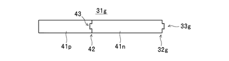
まず、図13に示す建築材料の他の一例としての建築材料3aの構成について説明する。建築材料3aは、建築物(上記した駆体100(図12参照)と同様の建築物)を建築するための建築材料であって、図14〜図17に示す4枚(3枚以上の一例)の板状材料31a〜31dを厚み方向(図13における紙面手前側と紙面奥側とを結ぶ方向)に積層して構成されている。   First, the configuration of a building material 3a as another example of the building material shown in FIG. 13 will be described. The building material 3a is a building material for building a building (a building similar to the above-described drive body 100 (see FIG. 12)), and four pieces (one example of three or more pieces) shown in FIGS. The sheet materials 31a to 31d are stacked in the thickness direction (the direction connecting the front side and the rear side in FIG. 13).

また、建築材料3aは、建築材料の他の一例としての建築材料3b(図19参照:以下、建築材料3a,3bを区別しないときには「建築材料3」ともいう)と互いに連結することが可能に構成されている。具体的には、図14〜図17に示すように、板状材料31a〜31dの各端部32a〜32dには、第1嵌合部33a〜33dが形成されている。また、図20〜図23に示すように、建築材料3bを構成する4枚(3枚以上の一例)の板状材料31e〜31hの各端部32e〜32hには、第1嵌合部33e〜33hが形成されている。そして、第1嵌合部33a〜33dと第1嵌合部33e〜33hとをそれぞれ嵌合させることにより、図24に示すように、建築材料3a,3bが互いに連結されて、建築材料ユニット70(建築材料の他の一例)が構成される。なお、以下の説明において、板状材料31a〜31hを区別しないときには「板状材料31」ともいい、端部32a〜32hを区別しないときには「端部32」ともいい、第1嵌合部33a〜33hを区別しないときには「第1嵌合部33」ともいう。   In addition, the building material 3a can be connected to the building material 3b as another example of the building material (see FIG. 19: hereinafter, when the building materials 3a and 3b are not distinguished from each other, it is also referred to as "building material 3") It is configured. Specifically, as shown in FIGS. 14 to 17, first fitting portions 33 a to 33 d are formed at the end portions 32 a to 32 d of the plate-like materials 31 a to 31 d. Further, as shown in FIGS. 20 to 23, the first fitting portion 33e is provided at each of the end portions 32e to 32h of the plate-like materials 31e to 31h of four sheets (one example of three or more sheets) constituting the building material 3b. To 33 h are formed. Then, by fitting the first fitting portions 33a to 33d and the first fitting portions 33e to 33h, respectively, the building materials 3a and 3b are connected to each other as shown in FIG. (Another example of building material) is configured. In the following description, when the plate-like materials 31a to 31h are not distinguished from each other, they are also referred to as "plate-like materials 31", and when the end parts 32a to 32h are not distinguished from each other, they are also referred to as "ends 32". When not distinguishing 33h, it is also called "the 1st fitting part 33."

この場合、各第1嵌合部33は、蟻継ぎ部を有して、建築材料3aにおける板状材料31の端部32と建築材料3bにおける板状材料31の端部32とを厚み方向から嵌め合い可能で、かつ嵌合状態において各板状材料31の板面に平行な方向であって互いに離反する向きでの各板状材料31の移動を規制可能に構成されている。なお、蟻継ぎ部に代えて、または蟻継ぎ部と共に、鎌継ぎ部を有して第1嵌合部33を構成することもできる。   In this case, each first fitting portion 33 has a dovetail portion, and the end 32 of the plate-like material 31 in the building material 3a and the end 32 of the plate-like material 31 in the building material 3b are viewed from the thickness direction It can be fitted, and in the fitted state, movement of each plate-like material 31 in a direction parallel to the plate surface of each plate-like material 31 and in a direction away from each other can be regulated. Note that, instead of the dovetail joint or together with the dovetail joint, the first fitting part 33 may be configured to have a joining joint.

また、この建築材料3では、図24に示すように、すべての板状材料31における各第1嵌合部33のすべてが、平面視状態において互いに重ならない部位に位置するように各第1嵌合部33の形成位置が規定されている。   Further, in this building material 3, as shown in FIG. 24, each first fitting portion 33 is positioned such that all of the first fitting portions 33 of all plate materials 31 do not overlap each other in plan view. The formation position of the joint portion 33 is defined.

また、この建築材料3では、各板状材料31が、図14〜図16および図20,22,23に示す板状パーツ41a〜41q(以下、区別しないときには「板状パーツ41」ともいう)の各端部42にそれぞれ形成されている第2嵌合部43同士を嵌合させることによって複数の板状パーツ41を連結して構成されている。   Moreover, in this building material 3, each plate-like material 31 is plate-like parts 41a-41q (it is also called "the plate-like parts 41" when it does not distinguish hereafter) shown to FIG. 14-FIG. 16 and FIG. The plurality of plate-like parts 41 are connected by fitting the second fitting portions 43 formed at the respective end portions 42 of the two.

また、各第2嵌合部43は、蟻継ぎ部を有して、各板状パーツ41の各端部42同士を厚み方向から嵌め合い可能で、かつ嵌合状態において各板状パーツ41の板面に平行な方向であって互いに離反する向きでの各板状パーツ41の移動を規制可能に構成されている。なお、蟻継ぎ部に代えて、または蟻継ぎ部と共に、鎌継ぎ部を有して第2嵌合部43を構成することもできる。   In addition, each second fitting portion 43 has a dovetail portion, and the respective end portions 42 of the respective plate-like parts 41 can be fitted from the thickness direction, and in the fitting state of the respective plate-like parts 41 The movement of each plate-like part 41 in a direction parallel to the plate surface and in a direction away from each other can be restricted. The second fitting portion 43 can also be configured to have a joint portion instead of the dovetail portion or together with the dovetail portion.

また、この建築材料3では、図13,19に示すように、すべての板状材料31における各第2嵌合部43のすべてが、平面視状態において互いに重ならない部位に位置するように各第2嵌合部43の形成位置が規定されている。   Further, in the building material 3, as shown in FIGS. 13 and 19, each of the second fitting portions 43 of all the plate-like materials 31 is positioned so as not to overlap each other in plan view. The formation position of the 2 fitting part 43 is prescribed.

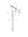
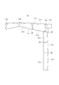
また、建築材料3aは、図13に示すように、支持部材51を備えている。この場合、支持部材51は、複数の板状パーツ41(複数の材料)を連結して構成した板状材料31よりも、長さ方向(図13に示す引っ張り力F2の作用方向であって、図13,18における左右方向)の引っ張り力に対して高い剛性(耐破断性)を有する材料で構成されている。この建築材料3aでは、一例として、鉄製の1本の棒材(丸棒)で支持部材51が構成されている。また、支持部材51は、図18に示すように、両端部52に雄ねじが形成され、図13に示すように、引っ張り力F2の作用方向(同図における左右方向)に沿って配設されると共に、板状材料31に両端部52が貫通された状態で、ナット61およびワッシャ62を用いて、両端部52が板状材料31に固定されている。なお、支持部材51を複数本配設した構成を採用することもできる。また、長さ方向の引っ張り力に対する剛性が板状材料31よりも高い材料である限り、上記した材料(鉄製の棒材)以外の各種の材料で支持部材51を構成することができる。例えば、鉄等の金属製の複数の棒材をターンバックル等を用いて連結したり、溶接によって接合したりして支持部材51を構成することができる。また、金属製のリング状材料を鎖状に連結して支持部材51を構成することもできる。さらに、長さ方向(引っ張り力F2の作用方向)の途中に継ぎ目のない各種木材、具体的には、無垢の木材や、長さ方向の途中に継ぎ目のない板材を複数積層した木材を用いることもできる。   Further, as shown in FIG. 13, the building material 3 a includes a support member 51. In this case, the support member 51 is longer than the plate-like material 31 formed by connecting a plurality of plate-like parts 41 (a plurality of materials) (in the action direction of the tensile force F2 shown in FIG. It is made of a material having high rigidity (breaking resistance) against the tensile force in the left and right direction in FIGS. In the building material 3a, as an example, the support member 51 is configured of a single bar (round bar) made of iron. Further, as shown in FIG. 18, the support member 51 has male screws formed at both end portions 52, and as shown in FIG. 13, the support member 51 is disposed along the acting direction (left and right direction in FIG. 18) of the pulling force F2. In the state where both ends 52 penetrate to plate-like material 31, both ends 52 are fixed to plate-like material 31 using nut 61 and washer 62. A configuration in which a plurality of support members 51 are disposed can also be adopted. Further, as long as the rigidity against the tensile force in the length direction is higher than that of the plate-like material 31, the support member 51 can be made of various materials other than the above-described materials (iron bars). For example, the support member 51 can be configured by connecting a plurality of metal rods such as iron using a turnbuckle or the like, or connecting them by welding. Alternatively, the support member 51 can be configured by connecting metal ring-shaped materials in a chain. Furthermore, use various types of lumber without joints in the middle of the length direction (direction of action of the tensile force F2), specifically, solid lumber, or lumbers in which plural plate members without joints are laminated in the middle of the length direction. You can also.

また、各板状材料31の厚みを薄く形成したり、積層する板状材料31の数を減じたりすることで、建築材料3aの全体の厚みが薄くなり、板状材料31に支持部材51の両端部52を貫通させることが困難なときには、図25,26に示すように、引寄せ金物(ホールダウン金物)63をボルト64およびナット61で固定し、その引寄せ金物63に支持部材51の両端部52をナット61で固定することもできる。   In addition, by forming the thickness of each plate-like material 31 thin or reducing the number of the plate-like materials 31 to be laminated, the overall thickness of the building material 3 a becomes thin. When it is difficult to penetrate both end portions 52, as shown in FIGS. 25 and 26, the pull-down hardware (hole down hardware) 63 is fixed by the bolt 64 and the nut 61, and the support member 51 is fixed to the pull-down hardware 63. Both end portions 52 can also be fixed by nuts 61.

この建築材料3aによれば、引っ張り力F2の作用方向に沿って配設されると共に板状材料31に両端部52が固定された支持部材51を備えたことにより、各板状材料31の長さ方向(図13における左右方向)に作用する引っ張り力F2を支えることができる。ここで、板状材料31のように複数の板状パーツ41を連結して構成した部材では、例えば、同図に示すように、板状材料31の長さ方向に対して下向きで直交する荷重F1が加わったときには、第2嵌合部43の上部を支点として、板状材料31における第2嵌合部43よりも右側の部分を左回り(反時計回り)に回動させ、板状材料31における第2嵌合部43よりも左側の部分を右回り(時計回り)に回動させるようなモーメントが生じ、このモーメントが板状材料31を長さ方向(同図における左右方向)に引っ張る引っ張り力F2として板状材料31に作用することがある。この場合、第2嵌合部43に大きな引っ張り力F2が加わったときには、第2嵌合部43に破壊が生じて板状材料31が第2嵌合部43の形成部位で折れ曲がるおそれがある。これに対して、支持部材51を備えたこの建築材料3aによれば、板状材料31に対して下向きに荷重F1が加わったとしても、各板状材料31の長さ方向に作用する引っ張り力F2を支持部材51によって支えることができるため、板状材料31が折れ曲がる事態を確実に防止することができる。したがって、この建築材料3aを建築物の梁や母屋として使用することで、積雪等によって建築物の屋根に大きな荷重F1が加わったとしても、その荷重F1に十分耐え得る建築物を建築することができる。   According to this construction material 3a, the length of each plate-like material 31 is provided by providing the support member 51 disposed along the action direction of the tensile force F2 and having the both ends 52 fixed to the plate-like material 31. A tensile force F2 acting in the longitudinal direction (left and right direction in FIG. 13) can be supported. Here, in a member formed by connecting a plurality of plate-like parts 41 like the plate-like material 31, for example, as shown in the figure, a load orthogonal to the length direction of the plate-like material 31 in a downward direction When F1 is added, the portion on the right side of the second fitting portion 43 in the plate material 31 is turned counterclockwise (counterclockwise) with the upper portion of the second fitting portion 43 as a fulcrum, A moment occurs such that the portion on the left side of the second fitting portion 43 at 31 is turned clockwise (clockwise), and this moment pulls the plate-like material 31 in the length direction (left and right direction in the same figure) It may act on the plate-like material 31 as a pulling force F2. In this case, when a large tensile force F2 is applied to the second fitting portion 43, the second fitting portion 43 may be broken and the plate-like material 31 may be bent at the formation portion of the second fitting portion 43. On the other hand, according to this building material 3a provided with the support member 51, even if the load F1 is applied downward to the plate-like material 31, the tensile force acting in the longitudinal direction of each plate-like material 31 Since F2 can be supported by the support member 51, the plate-like material 31 can be reliably prevented from bending. Therefore, by using this building material 3a as a beam or purlin of a building, even if a large load F1 is applied to the roof of the building due to snow accumulation, etc., a building that can sufficiently withstand the load F1 can be built. it can.

また、建築材料3a,3bでは、建築材料3a,3bを構成する4枚(3枚以上)の板状材料31における各第1嵌合部33のすべてが平面視状態において互いに重ならない部位に位置するように各第1嵌合部33の形成位置が規定されている。このため、この建築材料3a,3bによれば、各板状材料31の第1嵌合部33同士が嵌合している嵌合部分に対して、各板状材料31の板面に垂直な方向に外力が加わったとしても、他の板状材料31における第1嵌合部33の形成部位以外の非嵌合部分によってその外力が支えられて、外力の向きへの嵌合部分の移動(変位)を確実に規制することができる。したがって、この建築材料3a,3bによれば、このような外力によって第1嵌合部33同士の嵌合が解除される事態をより確実に防止することができる結果、この建築材料3a,3bを用いて建築した建築物の強度をさらに高めることができる。   Further, in the building materials 3a and 3b, all the first fitting portions 33 in the four (three or more) plate materials 31 constituting the building materials 3a and 3b do not overlap each other in plan view. The formation position of each first fitting portion 33 is defined as follows. For this reason, according to the building materials 3a and 3b, perpendicular to the plate surface of each plate-like material 31 with respect to the fitting portion in which the first fitting parts 33 of each plate-like material 31 are fitting. Even when an external force is applied in the direction, the external force is supported by the non-fitting portion other than the formation portion of the first fitting portion 33 in the other plate-like material 31, and the movement of the fitting portion in the direction of the external force Displacement) can be reliably regulated. Therefore, according to the building materials 3a and 3b, it is possible to prevent the situation in which the fitting of the first fitting portions 33 is released due to such an external force, and as a result, the building materials 3a and 3b can be obtained. It is possible to further enhance the strength of the building built using it.

また、建築材料3a,3bでは、建築材料3a,3bにおける4枚(3枚以上)の板状材料31を構成する各板状パーツ41の第2嵌合部43のすべてが平面視状態において互いに重ならない部位に位置するように各第2嵌合部43の形成位置が規定されている。このため、この建築材料3a,3bによれば、各板状パーツ41の第2嵌合部43同士が嵌合している嵌合部分に対して、各板状パーツ41の板面に垂直な方向に外力が加わったとしても、他の板状材料31の板状パーツ41における第2嵌合部43の形成部位以外の非嵌合部分によってその外力が支えられて、外力の向きへの嵌合部分の移動(変位)を確実に規制することができる。したがって、この建築材料3a,3bによれば、このような外力によって第2嵌合部43同士の嵌合が解除される事態を確実に防止することができる結果、この建築材料3a,3bを用いて建築した建築物の強度を一層高めることができる。   Further, in the building materials 3a and 3b, all of the second fitting portions 43 of the plate-like parts 41 constituting the four (three or more) plate-like materials 31 in the building materials 3a and 3b are mutually different in plan view The formation position of each second fitting portion 43 is defined so as to be located at a non-overlapping portion. Therefore, according to the building materials 3a and 3b, the perpendicular to the plate surface of each plate-like part 41 with respect to the fitting portion in which the second fitting parts 43 of each plate-like part 41 are fitted. Even if an external force is applied in the direction, the external force is supported by the non-fitting portion other than the formation portion of the second fitting portion 43 in the plate-like part 41 of the other plate-like material 31, and the external force is fitted in the direction. The movement (displacement) of the joint portion can be reliably restricted. Therefore, according to the building materials 3a and 3b, it is possible to reliably prevent the situation in which the second fitting portions 43 are disengaged due to such an external force. As a result, the building materials 3a and 3b are used. It can further enhance the strength of the built buildings.

1a,1b,3a,3b 建築材料
11a〜11d,31a〜31h 板状材料
12a〜12d,32a〜32h 端部
13a〜13d,33a〜33h 第1嵌合部
21a〜21i,41a〜41q 板状パーツ
22,42 端部
23,43 第2嵌合部
51 支持部材
100 駆体
F2 引っ張り力
1a, 1b, 3a, 3b Building materials 11a to 11d, 31a to 31h Plate-like materials 12a to 12d, 32a to 32h Ends 13a to 13d, 33a to 33h First fitting portions 21a to 21i, 41a to 41q Plate-like parts 22, 42 end 23, 43 second fitting portion 51 support member 100 drive F2 tensile force

Claims (10)

建築材料を用いて建築物を建築する建築工法であって、
前記建築材料は、板状材料を厚み方向に複数積層して構成され、当該建築材料における前記各板状材料の各端部にそれぞれ形成された各第1嵌合部と他の当該建築材料における前記各板状材料の各端部にそれぞれ形成された各第1嵌合部とをそれぞれ嵌合させることによって当該建築材料と当該他の建築材料とが連結可能に構成され、前記各第1嵌合部は、前記建築材料における前記各板状材料の前記各端部と前記他の建築材料における前記各板状材料の前記各端部とを前記厚み方向から嵌め合い可能で、かつ嵌合状態において前記各板状材料の板面に平行な方向であって互いに離反する向きでの当該各板状材料の移動を規制可能に構成されると共に、前記板状材料の前記第1嵌合部、および当該板状材料に隣接して積層されている他の前記板状材料の前記第1嵌合部が、平面視状態において互いに重ならない部位に位置するように当該各第1嵌合部の形成位置が規定され、
当該建築材料における前記各板状材料の前記各第1嵌合部と他の当該建築材料における前記各板状材料の前記各第1嵌合部とをそれぞれ嵌合させることによって連結させた当該各建築材料で前記建築物を建築する際に、
3枚の前記板状材料で構成されて、積層状態において、当該各板状材料のうちの前記厚み方向の中央に位置する板状材料の前記第1嵌合部が、他の2つの前記板状材料の前記各第1嵌合部よりも突出する前記建築材料としての第1建築材料と、
3枚の前記板状材料で構成されて、積層状態において、当該各板状材料のうちの前記厚み方向の両側部に位置する2つの板状材料の前記第1嵌合部が、当該厚み方向の中央に位置する板状材料の前記第1嵌合部よりも突出する前記他の建築材料としての第2建築材料とを用いて、
積層状態の前記第1建築材料における前記厚み方向の中央に位置する前記板状材料の前記第1嵌合部と、前記両側部に位置する2つの板状材料のいずれか一方における少なくとも前記第1嵌合部を含む部分が積層されていない状態の前記第2建築材料における前記厚み方向の中央に位置する前記板状材料の前記第1嵌合部とを嵌合させた後に、前記第1建築材料および前記第2建築材料における未嵌合の前記第1嵌合部同士を嵌合させて当該第1建築材料および当該第2建築材料を連結させた前記建築材料で前記建築物を建築する建築工法。
It is a construction method of building a building using building materials,
The building material is configured by laminating a plurality of plate materials in the thickness direction, and each first fitting portion formed at each end of each plate material in the building material and each other in the building material The building material and the other building material are configured to be connectable by respectively fitting the first fitting portions respectively formed at the end portions of the plate-like materials, and the first fitting The mating portion is capable of fitting the respective ends of the respective plate-like materials in the building material and the respective ends of the respective plate-like materials in the other building material from the thickness direction, and in a fitting state The first fitting portion of the plate-like material, wherein movement of the plate-like material in a direction parallel to the plate surface of each plate-like material and in a direction away from each other can be regulated; And the other above laminated adjacent to the plate-like material. Wherein the first fitting portion of the Jo material, the formation positions of the respective first fitting part so as to be positioned as not to overlap each other in a plan view state is defined,
The respective connected by fitting the first fitting portions of the plate-like materials in the building material and the first fitting portions of the plate-like materials in the other building materials, respectively When building the building with building materials,
The first fitting portion of the plate-like material, which is composed of three sheets of the plate-like material and is positioned at the center in the thickness direction of the respective plate-like materials in the laminated state, is the other two plates A first building material as the building material which protrudes beyond the first fitting portions of the second material;
The first fitting portions of the two plate-shaped materials which are made of the three plate-shaped materials and which are located on both sides in the thickness direction of the respective plate-like materials in the stacked state are the thickness direction Using the second building material as the other building material protruding beyond the first fitting portion of the plate-like material located at the center of the
At least a first of at least one of the first fitting portion of the plate-like material located at the center in the thickness direction of the first building material in a stacked state and one of two plate-like materials located at both sides. After fitting the first fitting portion of the plate-like material positioned at the center in the thickness direction of the second building material in a state in which the portion including the fitting portion is not stacked, the first building you building the building by the building material materials and the first fitting portions of the incomplete mating fitted in the second building material is connected to the first building material and the second building material architectural method.
前記板状材料の長さ方向に作用する引っ張り力を支える支持部材を備え、前記支持部材が、前記引っ張り力の作用方向に沿って配設されると共に前記板状材料に両端部が固定されている前記建築材料で前記建築物を建築する請求項1記載の建築工法。And a support member for supporting a tensile force acting in the longitudinal direction of the plate-like material, wherein the support member is disposed along the direction of action of the tensile force and both ends are fixed to the plate-like material The construction method according to claim 1, wherein the building is constructed of the building material. すべての前記板状材料における前記各第1嵌合部のすべてが、平面視状態において互いに重ならない部位に位置するように当該各第1嵌合部の形成位置が規定されている前記建築材料で前記建築物を建築する請求項1または2記載の建築工法。  In the building material, the formation positions of the respective first fitting portions are defined such that all the respective first fitting portions in all the plate-like materials are located at portions which do not overlap each other in a plan view state The construction method according to claim 1 or 2, wherein the building is constructed. 前記板状材料は、複数の板状パーツにおける各々の端部に形成された各第2嵌合部同士を嵌合させることによって当該各板状パーツを連結して構成され、前記各第2嵌合部が、前記各板状パーツの前記各端部を前記厚み方向から嵌め合い可能で、かつ嵌合状態において前記各板状パーツの板面に平行な方向であって互いに離反する向きでの当該各板状パーツの移動を規制可能に構成されている前記建築材料で前記建築物を建築する請求項1から3のいずれかに記載の建築工法。The plate-like material is formed by connecting the respective plate-like parts by fitting the respective second fitting parts formed at respective end portions of the plurality of plate-like parts, and the second fitting The joint portion is capable of fitting the respective end portions of the respective plate-like parts from the thickness direction and in a direction parallel to the plate surfaces of the respective plate-like parts in the fitting state and in a direction away from each other. The construction method according to any one of claims 1 to 3, wherein the building is constructed of the building material configured to be capable of restricting the movement of each plate-like part. 前記板状材料を構成する前記各板状パーツの前記各第2嵌合部、および当該板状材料に隣接して積層されている他の前記板状材料を構成する前記各板状パーツの前記各第2嵌合部が平面視状態において互いに重ならない部位に位置するように当該各第2嵌合部の形成位置が規定されている前記建築材料で前記建築物を建築する請求項4記載の建築工法。The second fitting portions of the plate-like parts constituting the plate-like material, and the plate-like parts constituting the other plate-like material stacked adjacent to the plate-like material The building according to claim 4, wherein the building is constructed of the building material in which the formation positions of the respective second fitting portions are defined such that the respective second fitting portions are located at portions which do not overlap each other in plan view state. Construction method. すべての前記板状材料における前記各第2嵌合部のすべてが、平面視状態において互いに重ならない部位に位置するように当該各第2嵌合部の形成位置が規定されている前記建築材料で前記建築物を建築する請求項5記載の建築工法。In the building material, the formation positions of the respective second fitting portions are defined such that all of the respective second fitting portions in all the plate-like materials are located at portions which do not overlap each other in a plan view state The construction method according to claim 5, wherein the building is constructed. 前記積層した各板状材料の間に塗布した接着剤によって当該各板状材料が固定されている前記建築材料で前記建築物を建築する請求項1から6のいずれかに記載の建築工法。The construction method according to any one of claims 1 to 6, wherein the building is constructed of the building material in which each plate-like material is fixed by an adhesive applied between the stacked plate-like materials. 前記積層した各板状材料がネジおよびボルトの少なくとも一方を用いて固定されている前記建築材料で前記建築物を建築する請求項1から7のいずれかに記載の建築工法。The construction method according to any one of claims 1 to 7, wherein the building is constructed with the building material in which the laminated plate-like materials are fixed using at least one of a screw and a bolt. 前記各建築材料を連結する際に、当該各建築材料における前記各板状材料が重なり合う部分に接着剤を塗布して当該重なり合う部分を固定する請求項からのいずれかに記載の建築工法。 The construction method according to any one of claims 1 to 8 , wherein when connecting the building materials, an adhesive is applied to the overlapping portions of the plate-like materials in the building materials to fix the overlapping portions. 前記各建築材料を連結する際に、当該各建築材料における前記各板状材料が重なり合う部分をネジおよびボルトの少なくとも一方を用いて固定する請求項からのいずれかに記載の建築工法。 The construction method according to any one of claims 1 to 9 , wherein when connecting the respective building materials, the overlapping portions of the respective plate materials in the respective building materials are fixed using at least one of a screw and a bolt.
JP2015137419A 2015-03-24 2015-07-09 Construction method Active JP6534878B2 (en)

Applications Claiming Priority (2)

Application Number Priority Date Filing Date Title
JP2015061035 2015-03-24

Publications (3)

Publication Number Publication Date
JP2016180296A JP2016180296A (en) 2016-10-13
JP2016180296A5 JP2016180296A5 (en) 2018-09-06
JP6534878B2 true JP6534878B2 (en) 2019-06-26

Family

ID=57132482

Family Applications (1)

Application Number Title Priority Date Filing Date
JP2015137419A Active JP6534878B2 (en) 2015-03-24 2015-07-09 Construction method

Country Status (1)

Country Link
JP (1) JP6534878B2 (en)

Family Cites Families (4)

* Cited by examiner, † Cited by third party
Publication number Priority date Publication date Assignee Title
JPS6029543Y2 (en) * 1977-09-30 1985-09-06 義春 小坂 wooden arch truss
JPH086375B2 (en) * 1991-11-14 1996-01-24 ミサワホーム株式会社 Bonding structure of laminated wood
JPH11129220A (en) * 1997-11-04 1999-05-18 Ichijyo Home Building Co Ltd Laminated lumber
CN1388774A (en) * 2000-08-10 2003-01-01 佩雷力家庭股份有限公司 Sweeping board and laminated wood

Also Published As

Publication number Publication date
JP2016180296A (en) 2016-10-13

Similar Documents

Publication Publication Date Title
JP2015506428A (en) Modular stud brace
US7775500B1 (en) Concrete forming system with interacting brackets connecting stacked form panels
JP2020002669A (en) Joint structure of woody shaft member
JP4625528B2 (en) Building unit structural member and floor structure using the unit structural member
JP6534878B2 (en) Construction method
JP6645193B2 (en) Horizontal material, structure for mounting surface material using horizontal material, and structure for mounting surface material and frame material using horizontal material
JP2017128981A (en) Wooden composite beam and construction method for the same
JP6837826B2 (en) Building reinforcement structure and reinforcement method
JP4997020B2 (en) Four-bolt jointed truss
JP6050209B2 (en) Ceiling structure
KR100637832B1 (en) Construction square pipe with assembly-connecting means
JP5445791B2 (en) Panel connection method
JP2018016978A (en) Structural member
JP7040721B2 (en) Truss frame and roof frame
JP6784381B2 (en) Composite material and metal plate used for it
JP2017110360A (en) Connection member and junction structure of floor joist
JP2016180296A5 (en)
JP4260736B2 (en) Steel house bearing wall structure
JP5271755B2 (en) Unit building
JP5612896B2 (en) Building installation structure
JP5749663B2 (en) Column structure
JP3180415U (en) Square bar assembly structure
JP6644367B1 (en) Earthquake-resistant wall
JP6297738B1 (en) Architectural connector, building forming unit, and building
JP6283443B1 (en) Architectural connector, building forming unit, and building

Legal Events

Date Code Title Description
A621 Written request for application examination

Free format text: JAPANESE INTERMEDIATE CODE: A621

Effective date: 20180307

A521 Request for written amendment filed

Free format text: JAPANESE INTERMEDIATE CODE: A523

Effective date: 20180712

A521 Request for written amendment filed

Free format text: JAPANESE INTERMEDIATE CODE: A523

Effective date: 20180724

A977 Report on retrieval

Free format text: JAPANESE INTERMEDIATE CODE: A971007

Effective date: 20181219

A131 Notification of reasons for refusal

Free format text: JAPANESE INTERMEDIATE CODE: A131

Effective date: 20181225

A521 Request for written amendment filed

Free format text: JAPANESE INTERMEDIATE CODE: A523

Effective date: 20190208

TRDD Decision of grant or rejection written
A01 Written decision to grant a patent or to grant a registration (utility model)

Free format text: JAPANESE INTERMEDIATE CODE: A01

Effective date: 20190528

A61 First payment of annual fees (during grant procedure)

Free format text: JAPANESE INTERMEDIATE CODE: A61

Effective date: 20190530

R150 Certificate of patent or registration of utility model

Ref document number: 6534878

Country of ref document: JP

Free format text: JAPANESE INTERMEDIATE CODE: R150

R250 Receipt of annual fees

Free format text: JAPANESE INTERMEDIATE CODE: R250