JP6533677B2 - Concrete coating method - Google Patents
Concrete coating method Download PDFInfo
- Publication number
- JP6533677B2 JP6533677B2 JP2015056552A JP2015056552A JP6533677B2 JP 6533677 B2 JP6533677 B2 JP 6533677B2 JP 2015056552 A JP2015056552 A JP 2015056552A JP 2015056552 A JP2015056552 A JP 2015056552A JP 6533677 B2 JP6533677 B2 JP 6533677B2
- Authority
- JP
- Japan
- Prior art keywords
- resin sheet
- concrete
- cone
- formwork
- hole
- Prior art date
- Legal status (The legal status is an assumption and is not a legal conclusion. Google has not performed a legal analysis and makes no representation as to the accuracy of the status listed.)
- Active
Links
- 238000000576 coating method Methods 0.000 title claims description 20
- 229920005989 resin Polymers 0.000 claims description 99
- 239000011347 resin Substances 0.000 claims description 99
- 238000009415 formwork Methods 0.000 claims description 35
- 239000000463 material Substances 0.000 claims description 35
- 238000000034 method Methods 0.000 claims description 28
- 229910000831 Steel Inorganic materials 0.000 claims description 14
- 239000010959 steel Substances 0.000 claims description 14
- 238000010276 construction Methods 0.000 claims description 12
- 239000011248 coating agent Substances 0.000 claims description 10
- -1 silane compound Chemical class 0.000 claims description 9
- 229920003002 synthetic resin Polymers 0.000 claims description 9
- 239000000057 synthetic resin Substances 0.000 claims description 9
- 229910000077 silane Inorganic materials 0.000 claims description 8
- 239000000945 filler Substances 0.000 claims description 4
- 239000000853 adhesive Substances 0.000 description 14
- 230000001070 adhesive effect Effects 0.000 description 14
- 238000004080 punching Methods 0.000 description 5
- 230000037303 wrinkles Effects 0.000 description 5
- 239000004820 Pressure-sensitive adhesive Substances 0.000 description 3
- 125000000217 alkyl group Chemical group 0.000 description 3
- 239000000839 emulsion Substances 0.000 description 3
- 230000009477 glass transition Effects 0.000 description 3
- 239000004570 mortar (masonry) Substances 0.000 description 3
- 150000003839 salts Chemical class 0.000 description 3
- 150000004756 silanes Chemical class 0.000 description 3
- 125000001424 substituent group Chemical group 0.000 description 3
- SJECZPVISLOESU-UHFFFAOYSA-N 3-trimethoxysilylpropan-1-amine Chemical compound CO[Si](OC)(OC)CCCN SJECZPVISLOESU-UHFFFAOYSA-N 0.000 description 2
- 229920000178 Acrylic resin Polymers 0.000 description 2
- 239000004925 Acrylic resin Substances 0.000 description 2
- XEEYBQQBJWHFJM-UHFFFAOYSA-N Iron Chemical compound [Fe] XEEYBQQBJWHFJM-UHFFFAOYSA-N 0.000 description 2
- 125000004432 carbon atom Chemical group C* 0.000 description 2
- 238000005266 casting Methods 0.000 description 2
- 230000007797 corrosion Effects 0.000 description 2
- 238000005260 corrosion Methods 0.000 description 2
- 230000006866 deterioration Effects 0.000 description 2
- 230000000694 effects Effects 0.000 description 2
- 238000010438 heat treatment Methods 0.000 description 2
- 230000035515 penetration Effects 0.000 description 2
- 229920003023 plastic Polymers 0.000 description 2
- 239000004033 plastic Substances 0.000 description 2
- 238000006116 polymerization reaction Methods 0.000 description 2
- 230000008569 process Effects 0.000 description 2
- 230000003014 reinforcing effect Effects 0.000 description 2
- 239000003381 stabilizer Substances 0.000 description 2
- LTOKKZDSYQQAHL-UHFFFAOYSA-N trimethoxy-[4-(oxiran-2-yl)butyl]silane Chemical compound CO[Si](OC)(OC)CCCCC1CO1 LTOKKZDSYQQAHL-UHFFFAOYSA-N 0.000 description 2
- WYTZZXDRDKSJID-UHFFFAOYSA-N (3-aminopropyl)triethoxysilane Chemical compound CCO[Si](OCC)(OCC)CCCN WYTZZXDRDKSJID-UHFFFAOYSA-N 0.000 description 1
- UUEWCQRISZBELL-UHFFFAOYSA-N 3-trimethoxysilylpropane-1-thiol Chemical compound CO[Si](OC)(OC)CCCS UUEWCQRISZBELL-UHFFFAOYSA-N 0.000 description 1
- XDLMVUHYZWKMMD-UHFFFAOYSA-N 3-trimethoxysilylpropyl 2-methylprop-2-enoate Chemical compound CO[Si](OC)(OC)CCCOC(=O)C(C)=C XDLMVUHYZWKMMD-UHFFFAOYSA-N 0.000 description 1
- 239000004593 Epoxy Substances 0.000 description 1
- 229920002472 Starch Polymers 0.000 description 1
- XTXRWKRVRITETP-UHFFFAOYSA-N Vinyl acetate Chemical compound CC(=O)OC=C XTXRWKRVRITETP-UHFFFAOYSA-N 0.000 description 1
- 240000008042 Zea mays Species 0.000 description 1
- 235000005824 Zea mays ssp. parviglumis Nutrition 0.000 description 1
- 235000002017 Zea mays subsp mays Nutrition 0.000 description 1
- 125000003277 amino group Chemical group 0.000 description 1
- 230000003712 anti-aging effect Effects 0.000 description 1
- 239000002518 antifoaming agent Substances 0.000 description 1
- DQXBYHZEEUGOBF-UHFFFAOYSA-N but-3-enoic acid;ethene Chemical compound C=C.OC(=O)CC=C DQXBYHZEEUGOBF-UHFFFAOYSA-N 0.000 description 1
- 239000003795 chemical substances by application Substances 0.000 description 1
- KRGNPJFAKZHQPS-UHFFFAOYSA-N chloroethene;ethene Chemical compound C=C.ClC=C KRGNPJFAKZHQPS-UHFFFAOYSA-N 0.000 description 1
- 235000005822 corn Nutrition 0.000 description 1
- 230000007423 decrease Effects 0.000 description 1
- 230000007547 defect Effects 0.000 description 1
- 238000007720 emulsion polymerization reaction Methods 0.000 description 1
- 125000003700 epoxy group Chemical group 0.000 description 1
- 239000003822 epoxy resin Substances 0.000 description 1
- NKSJNEHGWDZZQF-UHFFFAOYSA-N ethenyl(trimethoxy)silane Chemical compound CO[Si](OC)(OC)C=C NKSJNEHGWDZZQF-UHFFFAOYSA-N 0.000 description 1
- 239000005038 ethylene vinyl acetate Substances 0.000 description 1
- 238000004299 exfoliation Methods 0.000 description 1
- 238000000605 extraction Methods 0.000 description 1
- 230000006870 function Effects 0.000 description 1
- 230000008570 general process Effects 0.000 description 1
- 238000009434 installation Methods 0.000 description 1
- 229910052742 iron Inorganic materials 0.000 description 1
- 239000002184 metal Substances 0.000 description 1
- 229910052751 metal Inorganic materials 0.000 description 1
- 238000000465 moulding Methods 0.000 description 1
- 238000006386 neutralization reaction Methods 0.000 description 1
- 238000012856 packing Methods 0.000 description 1
- 230000002093 peripheral effect Effects 0.000 description 1
- 229920001200 poly(ethylene-vinyl acetate) Polymers 0.000 description 1
- 229920000647 polyepoxide Polymers 0.000 description 1
- 239000004800 polyvinyl chloride Substances 0.000 description 1
- 229920000915 polyvinyl chloride Polymers 0.000 description 1
- 238000003825 pressing Methods 0.000 description 1
- 230000009993 protective function Effects 0.000 description 1
- 238000003908 quality control method Methods 0.000 description 1
- 229920005573 silicon-containing polymer Polymers 0.000 description 1
- 239000008107 starch Substances 0.000 description 1
- 235000019698 starch Nutrition 0.000 description 1
- 238000003860 storage Methods 0.000 description 1
- 229920002803 thermoplastic polyurethane Polymers 0.000 description 1
- 229920005992 thermoplastic resin Polymers 0.000 description 1
- 239000002562 thickening agent Substances 0.000 description 1
- HHPPHUYKUOAWJV-UHFFFAOYSA-N triethoxy-[4-(oxiran-2-yl)butyl]silane Chemical compound CCO[Si](OCC)(OCC)CCCCC1CO1 HHPPHUYKUOAWJV-UHFFFAOYSA-N 0.000 description 1
- 125000000391 vinyl group Chemical group [H]C([*])=C([H])[H] 0.000 description 1
- 229920002554 vinyl polymer Polymers 0.000 description 1
Images


Description
本発明はコンクリートの表面を被覆する工法に関するものである。 The present invention relates to a method for coating the surface of concrete.
海岸部などのコンクリート構造物では飛来する塩分の影響により、劣化したコンクリート内の鉄筋が腐食する現象が知られている。
このような厳しい環境下におかれるコンクリート構造物では、その表面を耐久性の高い被膜で被覆して塩分などの劣化因子の浸入を防ぐ工法が開発されている。
その工法の一例として、特許文献1記載の表面被覆工法が公開されているが、この工法は、打設後のコンクリートへ有機または無機系の樹脂を複数層にわたって塗布し、塩害や中性化などの劣化を防止する工法である。
また他の例として、特許文献2記載の表面被覆工法が公開されているが、この工法は木製型枠の代わりに特殊なプラスチック製の型枠などを使用してコンクリートを打設し、アンカーやプライマーでコンクリートと一体化させる工法である。
In concrete structures such as coastal areas, it is known that reinforcing steels in degraded concrete may corrode due to the influence of the salt content coming in.
With concrete structures that are placed under such severe environments, a method has been developed in which the surface is coated with a highly durable coating to prevent the entry of deterioration factors such as salt.
As an example of the construction method, the surface covering construction method described in Patent Document 1 is disclosed. This construction method applies a plurality of layers of organic or inorganic resin to concrete after being cast, and causes salt damage, neutralization, etc. Method to prevent the deterioration of the
As another example, the surface covering method described in
前記した従来の表面被覆工法においては次のような問題点がある。
<1> 特許文献1に記載の工法では、樹脂の塗布に際してその前処理、下塗り、上塗りまで数日以上の作業時間が必要であり、その期間は躯体で他の作業を行うことができず、足場を設置したままの状態にしておく必要がある。
<2> 特許文献2に記載の工法では、特殊なプラスチック製の型枠を使用するために、一般の木製型枠にコンクリートを打設して脱型後にコンクリートの表面に樹脂を塗布して行う工法と比較した場合にコストが増加する。また型枠と被覆材を一体化させるためにアンカーの打設やプライマーの塗布作業が増加する。
The conventional surface coating method described above has the following problems.
<1> In the construction method described in Patent Document 1, a working time of several days or more is required to apply the resin to the pretreatment, undercoating, and topcoating, and other work can not be performed with the casing during that time, It is necessary to keep the scaffold installed.
<2> In the construction method described in
上記課題を解決するためになされた本願の第1発明は、被覆材としての樹脂シートをコンクリート打設側に取り付けた型枠を使用し、前記樹脂シートは、熱可塑性を有する合成樹脂からなり、前記合成樹脂は、100重量部に対してシラン化合物を0.1〜10重量部含有してあり、型枠をセパレーターで支持してコンクリートを打設し、コンクリートと樹脂シートが接着して、樹脂シートによってコンクリートを被覆させることを特徴とする、コンクリート被覆工法を提供するものである。
The first invention of the present application made to solve the above problems uses a mold having a resin sheet as a covering material attached to the concrete casting side, and the resin sheet is made of a synthetic resin having thermoplasticity, The synthetic resin contains 0.1 to 10 parts by weight of a silane compound per 100 parts by weight, the formwork is supported by a separator, concrete is placed, and the concrete and the resin sheet adhere to each other to form a resin. The present invention provides a concrete covering method characterized in that a sheet covers concrete.
また、本願の第2発明は、前記第1発明において、型枠と樹脂シートとの間に、剥離シートを設けることを特徴とするものである。 Further, according to a second invention of the present application, in the first invention, a release sheet is provided between the mold and the resin sheet.
また、本願の第3発明は、前記第1発明において、樹脂シートには、型枠を支持するセパレーターのコーンが当接する位置の周囲を除去してなる抜き穴、または前記コーンと接続する鋼棒を貫通させる貫通穴を形成しておき、コンクリートを打設した後に、型枠を解体してコーンを残置または除去し、コーンを除去した場合には、コンクリートのコーンの跡穴の内部に充填材を充填し、樹脂シートの抜き穴の内部に樹脂シートと同一の材料を塗布し、コーンを残置した場合には、樹脂シートの貫通穴の内部に樹脂シートと同一の材料を塗布することを特徴とするものである。
The third aspect of the present invention is the first invention, the resin sheet, a steel rod cone of the separator for supporting the mold to connect the contact to drain hole formed by removing the surrounding position or the cone, Form a through-hole to allow the penetration of concrete, and after placing concrete, dismantle the form to leave or remove the cone and remove the cone, fill the filling material inside the trace hole of the concrete cone filling the feature that the resin sheet and the same material is applied to the inside of the drain hole of the resin sheet, when leaving the cone, applying a same material as the resin sheet into the through hole of the resin sheet It is said that.
また、本願の第4発明は、前記第2発明において、剥離シートおよび樹脂シートには、型枠を支持するセパレーターのコーンが当接する位置の周囲を除去してなる抜き穴、または前記コーンと接続する鋼棒を貫通させる貫通穴を形成しておき、コンクリートを打設した後に、型枠を解体してコーンを残置または除去し、コーンを除去した場合には、コンクリートのコーンの跡穴の内部に、充填材を充填し、樹脂シートのコーンの抜き穴の内部に樹脂シートと同一の材料を塗布し、コーンを残置した場合には、樹脂シートの貫通穴の内部に樹脂シートと同一の材料を塗布することを特徴とするものである。
The fourth aspect of the present invention is the second invention, the release sheet and the resin sheet, punched hole cone separator for supporting the formwork is removed around the position abutting or connected to the cone, If a through hole through which the steel rod passes is formed and concrete is cast, the formwork is disassembled to leave or remove the cone, and if the cone is removed , the inside of the trace hole of the concrete cone in, filled with a filler, a resin sheet of the same material is applied to the inside of the vent holes in the resin sheet cone, when leaving the cone, inside the through holes of the resin sheet of the resin sheet same material It is characterized by apply | coating .
また、本願の第5発明は、前記第1発明乃至第4発明のうち何れか1つの発明において、樹脂シートを加熱して型枠面に張り付けることを特徴とするものである。
The fifth aspect of the present invention, in any one invention of the first invention to fourth invention, is characterized in that the paste into a mold surface by heating the resin sheet.
また、本願の第6発明は、前記第1発明乃至第5発明のうち何れか1つの発明において、型枠の一部をあらかじめ分割しておき、一部の型枠を先に脱型し、その後に他の型枠を順次脱型することを特徴とするものである。
The sixth aspect of the present invention, in any one invention of the first invention through the fifth invention, in advance divided part of the mold, demolded part of the mold earlier, After that, it is characterized in that other molds are sequentially removed from the mold.
本発明のコンクリート被覆工法は以上説明したようになるから、次のような効果を得ることができる。
<1> 現地での塗布作業では、厚さを均一に保つこと、ピンホールなどの欠陥を発生させないための施工管理、品質管理が必要である。しかし、本発明では、耐候性の高い樹脂を複数回にわたって塗布するような塗布工程がなく、形状の定まった樹脂シートを使用するから、作業が簡単で品質の高い被覆をコンクリートの表面に形成することができる。
<2> 樹脂シートを型枠の内側に取り付ける場合に、型枠を支持するセパレーターとの取付け部でシワが発生しやすい。しかし、本発明では、セパレーターと型枠の取付け部、すなわちコーンの周囲を切り抜き除去して抜き穴が形成してあるから、中間に樹脂シートが挟まることがなく、シワが発生することがない。
<3> コンクリートを打設した後にそのままの状態であると、樹脂シートに抜き穴が残ってしまう。しかし、本発明では、その抜き穴に樹脂シートと同一、類似の材料を塗布して充填するので、コンクリートの周囲を確実に被覆材で包囲することができる。
<4> コンクリートの脱型後に改めて表面被覆材の施工をする場合には、そのための足場などの仮設費用が発生する。しかし、本発明では、脱型時に表面被覆が完成するため、仮設費用を削減できる。
<5> 型枠が軽量であり、アンカーの施工やプライマーの塗布などの設備、作業が不要であるから施工性に優れる。
<6> 樹脂シートと型枠の全面とを、脱型時に型枠と一緒に樹脂シートが剥がれない程度の接着力を持つ粘着剤で接着することで、樹脂シートに生じるシワの発生を防止することができる。
Since the concrete coating method of the present invention is as described above, the following effects can be obtained.
<1> In the on-site application work, it is necessary to keep the thickness uniform, and to manage construction and quality control so as not to generate defects such as pinholes. However, in the present invention, since there is no application step of applying a highly weather resistant resin a plurality of times, and a resin sheet with a defined shape is used, an operation is easy and a high quality coating is formed on the surface of concrete. be able to.
<2> When attaching a resin sheet to the inside of a formwork, it is easy to generate a wrinkle in the attachment part with the separator which supports a formwork. However, in the present invention, since the attachment portion of the separator and the formwork, that is, the periphery of the cone is cut out and removed to form a hole, the resin sheet is not caught in the middle, and no wrinkles occur.
<3> If it is in the state after casting concrete, a hole will remain in the resin sheet. However, in the present invention, the same hole as the resin sheet is coated and filled with the same material as the resin sheet, so that the concrete can be reliably surrounded by the covering material.
<4> If construction of a surface covering material is to be performed again after demolding of concrete, temporary expenses such as scaffolding for that will occur. However, in the present invention, the temporary cost can be reduced because the surface coating is completed at the time of demolding.
<5> The formwork is lightweight, and facilities such as construction of the anchor and application of the primer, and work are not required, so the construction is excellent.
<6> By bonding the resin sheet and the entire surface of the mold together with the mold with a pressure sensitive adhesive that does not peel off the resin sheet together with the mold, generation of wrinkles in the resin sheet is prevented. be able to.
以下、図面を参照しながら、本発明のコンクリート被覆工法の実施形態を詳細に説明する。 Hereinafter, embodiments of the concrete covering method of the present invention will be described in detail with reference to the drawings.
本発明のコンクリート被覆工法では、以下のような型枠1を使用することができる。
(1)コンクリート7の打設側に剥離シート2を介して樹脂シート3を取り付けた型枠1(図1)。
(2)剥離シート2を介さずに直接、樹脂シート3を取り付けた型枠1(図示せず)。
型枠1自体は、通常の木製型枠1や鋼製型枠1を使用できる。
なお、後に説明するが、図8に示すように、型枠1の一部が分割しており、脱型時にその一部のみ取り外した後に残りの型枠1を取り外すような構造の型枠1を使用することもできる。
これは、脱型時に樹脂シート3または剥離シート2と型枠1とをひき剥がす際に、樹脂シート3がはがれる方向に生じる力を低減できるという効果を期待するためである。
In the concrete covering method of the present invention, the following form 1 can be used.
(1) A form 1 in which a
(2) A form 1 (not shown) to which the
As the form 1 itself, a usual wooden form 1 or steel form 1 can be used.
As will be described later, as shown in FIG. 8, a part of the mold 1 is divided, and the mold 1 having a structure in which only the part is removed at the time of mold removal and the remaining mold 1 is removed. Can also be used.
This is to expect the effect of reducing the force generated in the peeling direction of the
樹脂シート3は、コンクリート7の表面を被覆するための被覆材として機能するシートである。樹脂シート3には抜き穴4を開口する。
しかし、全面に粘着剤を塗布するような工法の場合は抜き穴4を省略することもでき、そのようなケースは後述する。
The
However, in the case of a method of applying an adhesive to the entire surface, the hole 4 can be omitted, and such a case will be described later.
被覆材としての樹脂シート3は、耐候性、耐食性に優れた被覆材を使用することができる。
耐食性に優れた被覆材としては、ウレタン樹脂、エポキシ樹脂、ポリ塩化ビニル樹脂、アクリル樹脂、エチレン酢ビ樹脂、などのエマルジョン系があげられる。
さらに好ましくは、アクリル樹脂、エチレン酢ビ樹脂である。
被覆材としての樹脂シート3は、上記の合成樹脂エマルジョンに安定剤や増粘剤、充填剤、消泡剤、老化防止剤を配合したものを、ロールコーターなどを使用して皮膜成型化して製造する。
ここでいう安定剤などは、特に限定するものではなく、市販のものを利用できる。
The
Examples of the coating material having excellent corrosion resistance include emulsion systems such as urethane resin, epoxy resin, polyvinyl chloride resin, acrylic resin, ethylene vinyl chloride resin and the like.
More preferably, they are acrylic resin and ethylene vinyl acetate resin.
The
The stabilizers and the like mentioned here are not particularly limited, and commercially available ones can be used.
樹脂シート3を構成する合成樹脂のガラス転移温度は、0℃から−50℃であり、好ましくは−5℃から−50℃である。
ガラス転移温度が0℃を超えて高い場合には、被覆材としての樹脂シート3自体が硬くなり、保護機能としての伸び性能が低下し、型枠1の設置作業時に割れを発生するなどの取り扱い性が低下する。
一方、ガラス転移温度が−50℃以下の場合には、表面のベタつきにより耐汚染性が低下したり、型枠1からの脱型時の剥離性も低下したりするので好ましくない。
そのような樹脂シート3を採用すると、熱可塑性を有し、40℃程度に加熱することで型枠と接着可能な樹脂シート3を得ることができる。
The glass transition temperature of the synthetic resin constituting the
When the glass transition temperature is higher than 0 ° C., the
On the other hand, when the glass transition temperature is -50 ° C. or less, it is not preferable because the stickiness of the surface lowers the stain resistance and the releasability at the time of demolding from the mold 1 also decreases.
When such a
被覆材としての樹脂シート3を構成する合成樹脂は、100重量部に対して、シラン化合物を0.1〜10重量部、含有した材料を採用することができる。
このシラン化合物の含有量は、好ましくは0.2重量部から5.0重量部であり、さらに好ましくは0.3から4.0重量部である。
その理由は、0.1重量部を超えて低い場合には、コンクリート7との接着力が低下し、10.0を超えて高い場合には、保存時の安定性が低下して取り扱い性がよくないからである。
シラン化合物を添加する方法としては、合成樹脂エマルジョンの重合時に導入する方法と、合成樹脂エマルジョン重合後に添加する方法があり、好ましくは重合時に導入する方法である。
樹脂シート3として上記の重量部のシラン化合物を含有させると、特別なアンカーやプライマーを用いなくとも、硬化後のコンクリート7と樹脂シート3との付着強度として1N/mm2以上を得ることができる。
The synthetic resin which comprises the
The content of the silane compound is preferably 0.2 to 5.0 parts by weight, and more preferably 0.3 to 4.0 parts by weight.
The reason is that when the amount is less than 0.1 part by weight, the adhesion to concrete 7 is reduced, and when it is more than 10.0, the stability during storage is reduced and the handling is improved. It is not good.
As a method of adding a silane compound, there are a method of introducing at the time of polymerization of a synthetic resin emulsion and a method of adding after a synthetic resin emulsion polymerization, preferably a method of introducing at the time of polymerization.
When the silane compound of the above-described weight part is contained as the
本発明の樹脂シートに含有させるシラン化合物は、特に制限はないが、下記一般式(1)で示すものであることが望ましい。 The silane compound to be contained in the resin sheet of the present invention is not particularly limited, but it is desirable that it is represented by the following general formula (1).
![]()
R1が置換基の場合、アミノ基、メタクリル基、ビニル基、エポキシ基、マルカプト基があげられる。
この中でも、アミノ基、エポキシ基、が好ましい。
シラン化合物は、具体的には、アミノプロピルトリメトキシシラン、アミノプロピルトリエトキシシラン、ビニルトリメトキシシラン、グリシジルプロピルトリメトキシシラン、グリシジルプロピルトリエトキシシラン、メルカプトプロピルトリメトキシシラン、メタクリロキシプロピルトリメトキシシランなどを挙げることができる。
この中でも、アミノプロピルトリメトキシシラン、グリシジルプロピルトリメトキシシランが好ましい。
シラン化合物は、さらに、R1の置換基が異なる2種以上のシラン化合物や、R2のアルキル基が異なる2種以上のシラン化合物を含有することができ、その組み合わせは特に制限がない。
![]()
When R 1 is a substituent, examples include amino, methacryl, vinyl, epoxy and malcapto groups.
Among these, an amino group and an epoxy group are preferable.
Specifically, the silane compound is, for example, aminopropyltrimethoxysilane, aminopropyltriethoxysilane, vinyltrimethoxysilane, glycidylpropyltrimethoxysilane, glycidylpropyltriethoxysilane, mercaptopropyltrimethoxysilane, methacryloxypropyltrimethoxysilane And the like.
Among these, aminopropyltrimethoxysilane and glycidylpropyltrimethoxysilane are preferable.
The silane compound may further contain two or more types of silane compounds having different substituents of R1, and two or more types of silane compounds having different alkyl groups of R2, and the combination thereof is not particularly limited.
剥離シート2は、樹脂シート3と弱い接着力で一体化してあるシートであり、樹脂シート3を型枠1面に取り付けるために設けるものである。
前記したように、剥離シート2の使用は不可欠ではないが、剥離シート2を使用する場合には、剥離シート2は型枠1の面積よりも多少大きい寸法のものを使用する。これは、型枠1からはみ出した剥離シート2の周囲を、型枠1に釘や剥離性に優れた粘着剤など、公知の方法で固定して一体化することができるためである(図2)。
The
As described above, the use of the
樹脂シート3または剥離シート2と、型枠1との接合には、剥離可能な粘着剤を使用する。
粘着剤としては、片面の接着力が大きく、他の面の粘着力が小さい両面テープや、接着力が小さくて型枠1の取り外しが可能な水溶性の粘着剤、のりなどを採用することができる。
両面テープとしては、例えばその粘着力が0.003〜1N/10mm2、さらに好ましくは0.1〜1N/0.2mm2程度のものを採用することができる。
付着強度がこれ以上の値の時には、脱型の際にコンクリート7とシート材がはがれる懸念があり、付着強度がこれ以下の値の時には、型枠1に設置したシートに浮きやはがれが生じてしまう懸念があるからである。
粘着剤のその他の例としては、主成分がでんぷん、酢酸ビニル、シリコーンポリマーである粘着剤を採用することができる。これらは脱型時に引きはがしが容易である。
また、鋼製型枠1に対しては、脱型時に加熱して剥離可能な熱可塑性を有する接着剤を採用すると、脱型時に加熱して剥離することができる。
剥離シート2を使用し、かつその剥離シート2が樹脂シート3より大きい場合には、剥離シート2の端を型枠1の桟木まで巻き込む状態で釘止めを行うことができる。
その場合、さらに釘を桟木の側面から打ち込む方法、あるいは正面から打ち込む方法を採用することができる。
脱型後に釘を引き抜ければ、剥離シート2を後で型枠1からはがすことが容易となる(図2(a)、図2(b))。
For bonding the
As the adhesive, double-sided tape with high adhesive strength on one side and small adhesive strength on the other side, or water-soluble adhesive with low adhesive strength and capable of removing the formwork 1, paste, etc. it can.
As a double-sided tape, for example, one having an adhesive strength of about 0.003 to 1 N / 10 mm 2 , and more preferably about 0.1 to 1 N / 0.2 mm 2 can be employed.
If the adhesion strength is more than this value, there is a concern that the
As another example of the pressure-sensitive adhesive, a pressure-sensitive adhesive whose main component is starch, vinyl acetate, or a silicone polymer can be adopted. These are easy to peel off at the time of demolding.
In addition, for the steel form 1, if an adhesive having thermoplasticity that can be heated and peeled off at the time of demolding is adopted, it can be heated and peeled off at the time of demolding.
When the
In that case, it is possible to adopt a method of driving a nail from the side of the crosspiece or a method of driving it from the front.
If the nail is pulled out after demolding, it becomes easy to peel off the
本発明において、剥離シート2の使用は不可欠ではないから、剥離シート2を使用しない場合には、樹脂シート3と型枠1を、前記のような剥離の容易な粘着剤で直接固定することができる。
あるいは、樹脂製の釘、ネジ、先端だけが金属のボルト、画鋲で直接型枠1に固定することもできる。
あるいは、熱可塑性を有する樹脂シート3を加熱して直接型枠1に接着することもできる。
In the present invention, since the use of the
Alternatively, it can be fixed directly to the form 1 with resin nails, screws, metal bolts only, and thumbtacks.
Alternatively, the
鉄筋を組み立て、その周囲を型枠1で包囲してコンクリート7を打設する基本の工程は、従来の一般の工程と同様である。
型枠1はその外側に水平、垂直にパイプなどの支保工8を配置してコンクリート7の圧力で型枠1が外側に転倒することを防止する構成を採用する(図3)。
同時に、型枠1が内側に移動しないように、型枠1のコンクリート7打設側、すなわち内側にセパレーター5を介在させて位置の維持を図る。
このセパレーター5とは、鋼棒の端にコーン6をねじ込み、このコーン6の外側の面を型枠1の内側面に接触させて位置を保持するもので、コンクリート工事では広く使用されている公知の部材である。
コーン6の当たる位置には、型枠1に貫通用に穴を開口しておき、この貫通穴を通して、コーン6の外側のねじ鋼棒を取り付けることができる。
このコーン6は、コンクリート7の硬化後に外側から専用の治具を使って引き抜いて除去する。
あるいは、コーン6の外側のねじ鋼棒のみを除去してコーン6を埋め殺しにすることもできる。
The basic process of assembling a reinforcing bar and surrounding it with the formwork 1 and placing
The formwork 1 adopts a configuration in which supports 8 such as pipes are disposed horizontally and vertically outside the formwork 1 to prevent the formwork 1 from falling outside due to the pressure of concrete 7 (FIG. 3).
At the same time, in order to prevent the formwork 1 from moving inward, the
The
At the position where the cone 6 abuts, a hole is formed in the form 1 for penetration, and the threaded steel rod on the outside of the cone 6 can be attached through the through hole.
After the
Alternatively, only the outer threaded steel rod of the cone 6 can be removed to saturate the cone 6.
この型枠1を組み立てる際に、剥離シート2および樹脂シート3には、コーン6が当接する位置の周囲を除去して抜き穴4を形成する。
抜き穴4を形成した後に、抜き穴4よりも十分に大きな剥離シート2などの紙を用意し、抜き穴4を形成したシートの剥離シート2側または型枠1側に設置する。
これは、切り取った抜き穴4の周囲にコンクリート7が回り込まないようにするためである。
こうしてセパレーター5のコーン6の外側面により樹脂シート3が固定されず、型枠1の内面とコーン6の端面との間に、剥離シート2や樹脂シート3を挟むことがなく、それらにシワが発生するおそれもない。
When assembling this formwork 1, in the
After forming the punching hole 4, a paper such as a
This is for the purpose of preventing the concrete 7 from going around the cut-out holes 4.
Thus, the
シワを発生させない他の方法として、型枠1を組み立てる際に、型枠1の全面と樹脂シート3または剥離シート2を接着する方法がある。
例えば、必要に応じて、塗布前に剥離シート2の一辺を釘などで型枠1と固定することで、樹脂シート3を型枠1の正確な位置に貼り付けることが可能となる。
または、型枠1の全面に剥離性のよい粘着剤の塗布、あるいは強弱両面テープの設置を行い、剥離シート2または樹脂シート3と型枠1の全面を貼り付ける方法がある(図3(b))。この方法によれば、全面が固定されるため、シートと型枠1の間への空気の導入がなくなり、シワの発生を防ぐことができる。
または、樹脂シート3と型枠1の全面を、釘や画鋲、ボルトなどで固定してもよい。このように構成すると、脱型時に型枠1が容易に取り外し可能なように、型枠1側からボルトを外すことが可能となる。
または、型枠1に力を加えることで、画鋲の針の部分が容易に外れる態様とする方法がある。例えば、画鋲の針の部分と頭の部分との接着力が画鋲の針の部分と型枠1の部分との接着力よりも弱くなるように構成しておけば、脱型時に型枠1に力を加えた際、画鋲の針の部分と頭の部分とが分離し、型枠1に針のみが残置した状態とすることができる。
または、熱可塑性の樹脂シート3をドライヤーやアイロンなどで少し加熱し、軟化させて型枠1の全面と貼り付け、ローラーで転圧して樹脂シート3を直接型枠1の全面と接着させることも可能である。
樹脂シート3は型枠1よりも若干大きくし、型枠1が重なる部分で樹脂シート3同士を重ね合わせ、目地処理の面積を減らすことも可能である。
また脱型時にはみ出たシートを抑えとし、コンクリート7と樹脂シート3との間にかかる力を低減することも可能である。
As another method for preventing generation of wrinkles, there is a method of bonding the entire surface of the mold 1 and the
For example, if necessary, by fixing one side of the
Alternatively, there is a method of applying an adhesive with good releasability to the entire surface of the form 1 or installing a strong and weak double-sided tape and pasting the entire surface of the
Alternatively, the entire surface of the
Alternatively, there is a method of applying a force to the mold 1 to make the part of the needle of the thumbtack come off easily. For example, if the adhesion between the needle part of the thumbtack and the head part is weaker than the adhesion between the needle part of the thumbtack and the part of the mold 1 When force is applied, the needle part and the head part of the thumbtack are separated, and only the needle can be left in the mold 1.
Alternatively, the
It is also possible to make the
Moreover, it is also possible to suppress the sheet | seat which overflowed at the time of demolding, and to reduce the force applied between the concrete 7 and the
以上の状態で、型枠1の内側にコンクリート7を打設する(図4)。
そして、コンクリート7が硬化した後に、型枠1を取り外し、その後に剥離シート2をはがす。
In the above state,
And after
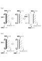
抜き穴4を形成してあると、コンクリート7の表面にコーン6の大径側の面が露出する。
そのコーン6を専用の治具を使って引き抜いて除去する(図5(a))。
するとコンクリート7にはコーン6の跡穴が残る。
また樹脂シート3には、抜き穴4が残り、その周囲にコンクリート7が付着した状態となる。
When the punching hole 4 is formed, the surface on the large diameter side of the cone 6 is exposed to the surface of the
The cone 6 is pulled out and removed using a dedicated jig (FIG. 5 (a)).
Then, the mark hole of cone 6 remains in concrete 7.
Further, in the
抜き穴4を形成しなかった場合には、樹脂を全面に塗布することになり、コーン6の外側の鋼棒の一部が樹脂シート3を貫通して残っている状態である。
その鋼棒のみを取り外すと、コンクリート7表面には鋼棒の貫通した穴のみが残る(図5(b))。
When the punched hole 4 is not formed, the resin is applied to the entire surface, and a part of the steel rod outside the cone 6 penetrates the
When only the steel rod is removed, only the through holes of the steel rod remain on the surface of the concrete 7 (FIG. 5 (b)).
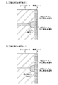
コンクリート7のコーン6の跡穴は、その内部にモルタルなどの充填材を充填して、セパレーター5の端部が外部に露出しないように絶縁する(図6)。
あるいは、コーン6を埋め殺すこともできる(図7(b))。
The mark holes of the cone 6 of the
Alternatively, the corn 6 can be buried and killed (FIG. 7 (b)).
被覆材としての樹脂シート3の抜き穴4の周囲にはコンクリート7が付着している場合があるので、それを外部から除去する。
そして、樹脂シート3のコーン6の跡穴の内部には樹脂シート3と同一あるいは類似の材料の塗布材を塗布する(図7(a))。
同時に樹脂シート3と塗布材の境界にも類似の材料を塗布する。
あるいは、鋼棒の貫通した穴に、樹脂シート3と同一あるいは類似する材料を塗布する(図7(b))。
あるいは、樹脂製のパッキンのような円盤状のシートを用意し、それを接着することで容易に補修することができる。
その場合にも樹脂シート3と塗布材の間にも類似の材料を塗布する。
こうしてコンクリート7の表面を、簡単にかつ完全に被覆材で被覆することができる。
Then, an application material of the same or similar material as that of the
At the same time, a similar material is applied to the boundary between the
Alternatively, the same or similar material as the
Alternatively, it can be easily repaired by preparing a disk-like sheet such as a resin packing and bonding it.
In that case, similar materials are applied also between the
In this way, the surface of the
本発明に係る型枠1は複数に分割可能に構成することもできる。
図8に示す型枠1は、型枠Aと型枠Bの上下二つ、あるいは複数に分割している。
この分割した型枠A,Bのコンクリート7の打設面の境界部に、薄いテープを張り付けて仮押さえを行う。
一方、両型枠1の反対側の境界部を、はらみ防止のためクランプ9などで固定する。
次に、型枠1の打設面側の全面に、剥離シート2を介して樹脂シート3を接着剤で張り付ける。
次に、型枠1からはみ出している剥離シート2の周辺部は、型枠1側へ折りたたんで針などで型枠1に固定する。
次に、樹脂シート3のコンクリート7打設側には、モルタル製のコーン6を介してセパレーター5を取り付ける。
この状態でコンクリート7を打設し、硬化したらクランプ9を外し、上下の型枠1の一体性を解除する。
そして、型枠1を部分ごとに取り外し、剥離シート2を剥がして除去する。
このような工程によって、樹脂シート3に作用する、該樹脂シート3を剥がれる方向に生じる力を軽減した状態で、コンクリート7の表面を樹脂シート3で保護することができる。
The mold 1 according to the present invention can also be configured to be divisible into a plurality.
The formwork 1 shown in FIG. 8 is divided into upper and lower two or more of the formwork A and the formwork B.
A thin tape is attached to the boundary between the cast surfaces of the
On the other hand, the boundary part on the opposite side of both the formwork 1 is fixed by clamp 9 etc. in order to prevent a flare.
Next, the
Next, the peripheral portion of the
Next, the
In this state,
Then, the form 1 is removed part by part, and the
By such a process, the surface of the
1:型枠
2:剥離シート
3:樹脂シート
4:抜き穴
5:セパレーター
6:コーン
7:コンクリート
8:支保工
9:クランプ
1: Form 2: release sheet 3: resin sheet 4: extraction hole 5: separator 6: cone 7: concrete 8: support 9: clamp
Claims (6)
前記樹脂シートは、熱可塑性を有する合成樹脂からなり、
前記合成樹脂は、100重量部に対してシラン化合物を0.1〜10重量部含有してあり、
型枠をセパレーターで支持してコンクリートを打設し、
コンクリートと樹脂シートが接着して、樹脂シートによってコンクリートを被覆させることを特徴とする、
コンクリート被覆工法。 Use a formwork with a resin sheet as a covering material attached to the concrete placement side,
The resin sheet is made of a synthetic resin having thermoplasticity,
The synthetic resin contains 0.1 to 10 parts by weight of a silane compound per 100 parts by weight,
The formwork is supported by a separator and concrete is cast,
Bonding the concrete and the resin sheet and coating the concrete with the resin sheet,
Concrete coating method.
型枠と樹脂シートとの間に、剥離シートを設けることを特徴とする、
コンクリート被覆工法。 In the method according to claim 1,
A release sheet is provided between the mold and the resin sheet,
Concrete coating method.
樹脂シートには、型枠を支持するセパレーターのコーンが当接する位置の周囲を除去してなる抜き穴、または前記コーンと接続する鋼棒を貫通させる貫通穴を形成しておき、
コンクリートを打設した後に、型枠を解体してコーンを残置または除去し、
コーンを除去した場合には、コンクリートのコーンの跡穴の内部に充填材を充填し、樹脂シートの抜き穴の内部に樹脂シートと同一の材料を塗布し、
コーンを残置した場合には、樹脂シートの貫通穴の内部に樹脂シートと同一の材料を塗布する、
ことを特徴とする、
コンクリート被覆工法。 In the method according to claim 1,
The resin sheet is previously formed a through hole through which the steel rod cone of the separator to support the mold is connected to the drain hole formed by removing the surrounding position abutting or said cone,
After placing concrete, dismantle the form and leave or remove the cone,
When removing the cone, filled with a filler inside the mark hole in the concrete cone, a resin sheet and the same material is applied to the inside of the drain hole of the resin sheet,
If the cone is left, apply the same material as the resin sheet inside the through hole of the resin sheet,
It is characterized by
Concrete coating method.
剥離シートおよび樹脂シートには、型枠を支持するセパレーターのコーンが当接する位置の周囲を除去してなる抜き穴、または前記コーンと接続する鋼棒を貫通させる貫通穴を形成しておき、
コンクリートを打設した後に、型枠を解体してコーンを残置または除去し、
コーンを除去した場合には、コンクリートのコーンの跡穴の内部に、充填材を充填し、樹脂シートのコーンの抜き穴の内部に樹脂シートと同一の材料を塗布し、
コーンを残置した場合には、樹脂シートの貫通穴の内部に樹脂シートと同一の材料を塗布する、
ことを特徴とする、
コンクリート被覆工法。 In the method according to claim 2,
Release sheet and the resin sheet is previously formed a through hole through which the steel rod cone of the separator to support the mold is connected to the drain hole formed by removing the surrounding position abutting or said cone,
After placing concrete, dismantle the form and leave or remove the cone,
When the cone is removed , fill the filling material inside the mark hole of the concrete cone, and apply the same material as the resin sheet inside the hole of the resin sheet cone,
If the cone is left, apply the same material as the resin sheet inside the through hole of the resin sheet,
It is characterized by
Concrete coating method.
樹脂シートを加熱して型枠面に張り付けることを特徴とする、
コンクリート被覆工法。 In the method according to any one of claims 1 to 4 ,
The resin sheet is heated and attached to the surface of the formwork,
Concrete coating method.
型枠の一部をあらかじめ分割しておき、一部の型枠を先に脱型し、その後に他の型枠を順次脱型することを特徴とする、
コンクリート被覆工法。 In the construction method according to any one of claims 1 to 5 ,
A part of the formwork is divided in advance, a part of the formwork is demolded first, and then the other formwork is demolded sequentially.
Concrete coating method.
Priority Applications (1)
| Application Number | Priority Date | Filing Date | Title |
|---|---|---|---|
| JP2015056552A JP6533677B2 (en) | 2015-03-19 | 2015-03-19 | Concrete coating method |
Applications Claiming Priority (1)
| Application Number | Priority Date | Filing Date | Title |
|---|---|---|---|
| JP2015056552A JP6533677B2 (en) | 2015-03-19 | 2015-03-19 | Concrete coating method |
Publications (2)
| Publication Number | Publication Date |
|---|---|
| JP2016176231A JP2016176231A (en) | 2016-10-06 |
| JP6533677B2 true JP6533677B2 (en) | 2019-06-19 |
Family
ID=57069007
Family Applications (1)
| Application Number | Title | Priority Date | Filing Date |
|---|---|---|---|
| JP2015056552A Active JP6533677B2 (en) | 2015-03-19 | 2015-03-19 | Concrete coating method |
Country Status (1)
| Country | Link |
|---|---|
| JP (1) | JP6533677B2 (en) |
Families Citing this family (1)
| Publication number | Priority date | Publication date | Assignee | Title |
|---|---|---|---|---|
| JP7125859B2 (en) * | 2018-05-23 | 2022-08-25 | 株式会社ケー・エフ・シー | Punch repair seal and repair method |
Family Cites Families (7)
| Publication number | Priority date | Publication date | Assignee | Title |
|---|---|---|---|---|
| JPS538189Y2 (en) * | 1973-03-06 | 1978-03-03 | ||
| JPS5044626A (en) * | 1973-08-26 | 1975-04-22 | ||
| JPS59146453U (en) * | 1983-03-17 | 1984-09-29 | 株式会社竹中工務店 | concrete formwork wood cone |
| JPS59199921A (en) * | 1983-04-25 | 1984-11-13 | Fukubi Kagaku Kogyo Kk | Ant preventive foundation work |
| DE19623584B4 (en) * | 1996-06-13 | 2004-10-14 | Johns Manville International, Inc., Denver | Textile fabric for use as a concrete form liner |
| JPH11210226A (en) * | 1998-01-20 | 1999-08-03 | Sumitomo Rubber Ind Ltd | Separator of form material for concrete |
| JP3860783B2 (en) * | 2002-08-28 | 2006-12-20 | みらい建設工業株式会社 | Existing structure covering member and existing structure covering method |
-
2015
- 2015-03-19 JP JP2015056552A patent/JP6533677B2/en active Active
Also Published As
| Publication number | Publication date |
|---|---|
| JP2016176231A (en) | 2016-10-06 |
Similar Documents
| Publication | Publication Date | Title |
|---|---|---|
| US9062453B1 (en) | Expansion/control joint for stucco surfaces | |
| JP2005510645A (en) | Grooved edge building panel and manufacturing method | |
| US20220111608A1 (en) | Wall and ceiling repair products and methods | |
| JP6533677B2 (en) | Concrete coating method | |
| JP2018031012A (en) | Method of manufacturing article and adhesive sheet | |
| JP7173193B2 (en) | Article manufacturing method and stacking device | |
| KR101546733B1 (en) | Waterproof and root isolation method for fiber reinforced plastics | |
| JP2015078487A (en) | Repair structure and repair method of building surface | |
| JP2007177462A (en) | Fiber reinforced skeleton structure and its manufacturing method | |
| JP7031130B2 (en) | Renovation structure of existing outer wall and renovation method of existing outer wall | |
| KR101243492B1 (en) | Water-proofing method combined fiberglass reinforced plastic(FRP) and membrane water-proofing | |
| JP6996072B2 (en) | Renovation structure of existing outer wall and renovation method of existing outer wall | |
| JP7116693B2 (en) | Method for repairing stone structures | |
| JP3975925B2 (en) | Bonding method, bonding structure | |
| JP7125859B2 (en) | Punch repair seal and repair method | |
| JP5281117B2 (en) | Unit tile construction method | |
| JP3156267U (en) | Curing sheet for concrete surface sticking | |
| JP2020042018A (en) | Peeling resistance evaluation method of paint floor material painted on ground | |
| JP5147628B2 (en) | Crack repair method for concrete structures using primer. | |
| JP6911297B2 (en) | Building exterior wall repair method | |
| JPH0245378Y2 (en) | ||
| JP2017110343A (en) | Structure and method for repairing existing exterior wall | |
| CN207553550U (en) | A kind of big face brick construction auxiliary of interior wall applies G system | |
| JPS60215970A (en) | Exterior tile adhering method | |
| TW202328545A (en) | Structure protection sheet and method for manufacturing reinforced structure |
Legal Events
| Date | Code | Title | Description |
|---|---|---|---|
| A621 | Written request for application examination |
Free format text: JAPANESE INTERMEDIATE CODE: A621 Effective date: 20171207 |
|
| A977 | Report on retrieval |
Free format text: JAPANESE INTERMEDIATE CODE: A971007 Effective date: 20181012 |
|
| A131 | Notification of reasons for refusal |
Free format text: JAPANESE INTERMEDIATE CODE: A131 Effective date: 20181023 |
|
| A521 | Request for written amendment filed |
Free format text: JAPANESE INTERMEDIATE CODE: A523 Effective date: 20181219 |
|
| TRDD | Decision of grant or rejection written | ||
| A01 | Written decision to grant a patent or to grant a registration (utility model) |
Free format text: JAPANESE INTERMEDIATE CODE: A01 Effective date: 20190514 |
|
| A61 | First payment of annual fees (during grant procedure) |
Free format text: JAPANESE INTERMEDIATE CODE: A61 Effective date: 20190527 |
|
| R150 | Certificate of patent or registration of utility model |
Ref document number: 6533677 Country of ref document: JP Free format text: JAPANESE INTERMEDIATE CODE: R150 |
|
| R250 | Receipt of annual fees |
Free format text: JAPANESE INTERMEDIATE CODE: R250 |
|
| R250 | Receipt of annual fees |
Free format text: JAPANESE INTERMEDIATE CODE: R250 |
|
| R250 | Receipt of annual fees |
Free format text: JAPANESE INTERMEDIATE CODE: R250 |