JP6532769B2 - Runout correction method for machine tools and tools - Google Patents
Runout correction method for machine tools and tools Download PDFInfo
- Publication number
- JP6532769B2 JP6532769B2 JP2015124945A JP2015124945A JP6532769B2 JP 6532769 B2 JP6532769 B2 JP 6532769B2 JP 2015124945 A JP2015124945 A JP 2015124945A JP 2015124945 A JP2015124945 A JP 2015124945A JP 6532769 B2 JP6532769 B2 JP 6532769B2
- Authority
- JP
- Japan
- Prior art keywords
- tool
- phase
- spindle
- shake
- tool holder
- Prior art date
- Legal status (The legal status is an assumption and is not a legal conclusion. Google has not performed a legal analysis and makes no representation as to the accuracy of the status listed.)
- Active
Links
Images

Landscapes
- Automatic Tool Replacement In Machine Tools (AREA)
- Machine Tool Sensing Apparatuses (AREA)
- Automatic Control Of Machine Tools (AREA)
Description
本発明は、工具を装着した工具ホルダを主軸に自動着脱する着脱機構を備えた工作機械に関し、特に、主軸の回転軸に対する工具の振れを自動的に修正することができる工作機械及び工具の振れ修正方法に関する。 The present invention relates to a machine tool provided with an attachment / detachment mechanism for automatically attaching / detaching a tool holder equipped with a tool to / from a spindle, and in particular, a runout of a machine tool and a tool capable of automatically correcting a runout of a tool with respect to a spindle rotation axis. Regarding the correction method.
従来、工作機械の主軸に取り付けた工具の交換を行う自動工具交換装置において、主軸に取り付けた工具の芯振れを検出するための検出手段として、接触式の電気マイクロメータなどを備えたものが知られている(例えば、特許文献1参照)。特許文献1に記載の工作機械は、主軸に取り付けた工具の芯振れを検出し、工具が精度よく主軸に取り付けられていないと判断された場合には工具の再取り付けが行われ、工具が精度よく主軸に取り付けられていると判断された場合には加工を行う。
Heretofore, an automatic tool changer for replacing a tool attached to a spindle of a machine tool has been known which is provided with a contact-type electric micrometer or the like as a detection means for detecting a runout of a tool attached to the spindle. (See, for example, Patent Document 1). The machine tool described in
近年、マシニングセンタなどの工作機械では、工具の長寿命化や加工面精度の更なる向上が要求されている。しかし、一般的なマシニングセンタとして普及している工具を装着した工具ホルダを主軸に自動着脱する着脱機構を備えた工作機械では、工具を工具ホルダに装着する際に生じるズレ及び工具ホルダを主軸に装着する際に生じるズレが重畳されて工具の芯振れが大きくなることがある。 In recent years, in machine tools such as machining centers, longer tool life and further improvement of machining surface accuracy are required. However, in a machine tool equipped with an attachment / detachment mechanism for automatically attaching / detaching a tool holder equipped with a tool popularized as a general machining center to a spindle, displacement occurring when attaching a tool to the tool holder and attachment of the tool holder to the spindle Deviations that occur during operation may be superimposed, which may increase the runout of the tool.
この工作機械で高度な面精度を要求される加工を行う場合には、工具ホルダに工具を装着した後、主軸に該工具ホルダを取り付け、工具の芯振れを検出するための検出手段を用いて工具の芯振れを確認している。検出した工具の芯振れが目標値より大きい場合には、a)工具を工具ホルダから取り外して工具の取り付け位相を変更するか、b)工具ホルダを主軸から取り外して工具ホルダの取り付け位相を変更し、再度工具の芯振れを確認している。検出した工具の芯振れが目標値に収まるまでこの手順を繰り返し、工具の芯振れが目標値に収まった状態で加工を行っている。 When processing requiring high surface accuracy is performed with this machine tool, after the tool is mounted on the tool holder, the tool holder is mounted on the spindle and detection means for detecting the runout of the tool is used. The runout of the tool has been confirmed. If the detected run-out of the tool is larger than the target value, either a) remove the tool from the tool holder and change the mounting phase of the tool, or b) remove the tool holder from the spindle and change the mounting phase of the tool holder. , Again confirmed the tool runout. This procedure is repeated until the detected run-out of the tool falls within the target value, and machining is performed in a state in which the run-out of the tool falls within the target value.
特許文献1に記載の工作機械は、主軸に取り付けた工具の芯振れを検出し、この芯振れが一定の範囲を超えた場合に、工具が精度よく主軸に取り付けられていない状態であると判断し、精度が悪い状態での加工を行わないようにすることはできる。しかし、特許文献1に記載の工作機械は、自動工具交換装置による主軸への工具の装着不良を検出し、工具の再取り付けによって装着不良を解消するものに過ぎないので、工具の芯振れを更に小さくすることができるように、高精度に工具を主軸に装着することはできないという課題があった。
The machine tool described in
また、工具の芯振れを検出し、検出した工具の芯振れが目標値より大きい場合に、a)工具を工具ホルダから取り外して工具の取り付け位相を変更するか、b)工具ホルダを主軸から取り外して工具ホルダの取り付け位相を変更し、検出した工具の芯振れが目標値に収まるまでこの手順を繰り返すことによって工具の芯振れを更に小さくすることはできるが、工具の取り付けに多大な労力を要するという問題があった。また、この手法では、検出した工具の芯振れが目標値に収まるまで必要な手順を繰り返すだけなので、目標値を高く設定すると工具の取り付けに要する労力が大きくなり、目標値を低く設定すると工具の取り付け精度が低下するという問題があった。 Also, if the tool runout is detected and the detected runout of the tool is greater than the target value, a) remove the tool from the tool holder and change the mounting phase of the tool, or b) remove the tool holder from the spindle Tool runout can be further reduced by changing the mounting phase of the tool holder and repeating this procedure until the detected runout of the tool falls within the target value, but it takes a lot of labor to install the tool There was a problem that. Also, in this method, only the necessary procedure is repeated until the detected run-out of the tool falls within the target value, so if the target value is set high, the labor required for mounting the tool becomes large, and if the target value is set low, the tool There is a problem that the mounting accuracy is reduced.
そこで、本発明は、工具を装着した工具ホルダを主軸に自動着脱する着脱機構を備えた工作機械において、主軸の回転軸に対する工具の振れを自動的に修正して工具の高精度な取り付けを可能にする工作機械及び工具の振れ修正方法を提供するものである。 Therefore, according to the present invention, in a machine tool provided with an attaching / detaching mechanism for automatically attaching / detaching a tool holder equipped with a tool to / from the spindle, the deflection of the tool with respect to the spindle of the spindle can be automatically corrected to mount the tool with high accuracy. And provide a method for correcting run-out of a machine tool and a tool.
本発明は、上記課題を解決するために、工具を装着した工具ホルダを主軸に自動着脱する着脱機構を備えた工作機械であって、前記主軸の回転時に、前記主軸の回転軸に対する前記主軸、前記工具ホルダ及び前記工具で構成される回転系の振れを測定する振れセンサと、前記工具ホルダを前記主軸に対して異なる位相で装着する位相制御機構と、を有し、前記位相制御機構が、二以上の異なる位相において測定した前記回転系の振れを比較し、該振れが最小となる位相で前記工具ホルダを前記主軸に装着する振れ修正機構を備えた工作機械を提供するものである。 The present invention is a machine tool provided with an attachment / detachment mechanism for automatically attaching / detaching a tool holder equipped with a tool to / from a spindle in order to solve the above-mentioned problems, wherein the spindle with respect to the rotation axis of the spindle when the spindle rotates. And a phase control mechanism for mounting the tool holder at different phases with respect to the spindle, the phase control mechanism comprising: a shake sensor for measuring a shake of a rotation system including the tool holder and the tool; It is an object of the present invention to provide a machine tool provided with a shake correction mechanism which mounts the tool holder on the spindle at a phase where the shake is minimized by comparing the shakes of the rotary system measured at two or more different phases.
また、本発明の工作機械は、前記振れ修正機構が、前記主軸に対する前記工具ホルダの位相を変えて前記回転系の振れを測定する回数で360°を等分した所定角度ずつ前記工具ホルダの位相を変えて前記回転系の振れを測定するものである。 Further, in the machine tool of the present invention, the phase of the tool holder is divided by a predetermined angle equally dividing 360 ° by the number of times the shake correction mechanism changes the phase of the tool holder with respect to the spindle to measure the shake of the rotating system. To measure the swing of the rotating system.
また、本発明の工作機械は、前記振れセンサが、前記工具の振れを測定する光学センサ又は/及び前記主軸の振動を測定する振動センサを含むものである。 Further, in the machine tool of the present invention, the shake sensor includes an optical sensor that measures a shake of the tool and / or a vibration sensor that measures a vibration of the spindle.
また、本発明の工作機械は、前記光学センサで測定した前記工具の振れが最小となる位相と前記振動センサで測定した前記主軸の振動が最小となる位相が異なる場合に、前記振れ修正機構は、前記工具の振れ及び前記主軸の振動の双方が許容範囲内であるか否かを判断し、一の位相のみが該条件を満たすときには該位相を前記回転系の振れ及び振動が最小となる位相であると判断し、何れの位相も該条件を満たす又は何れの位相も該条件を満たさないときには前記工具の振れが最小となる位相を前記回転系の振れ及び振動が最小となる位相であると判断することを特徴とする。 Further, in the machine tool according to the present invention, the shake correction mechanism is configured to move the shake correction mechanism when the phase in which the shake of the tool measured by the optical sensor is minimum differs from the phase in which the vibration of the spindle measured by the vibration sensor is minimum. It is determined whether both the swing of the tool and the vibration of the spindle are within an allowable range, and when only one phase satisfies the condition, the phase is a phase at which the swing and vibration of the rotary system are minimized. If it is determined that any phase satisfies the condition or no phase satisfies the condition, the phase at which the swing of the tool is minimum is the phase at which the swing and vibration of the rotation system are minimum. It is characterized by judging.
また、本発明の工作機械は、前記振れ修正機構が、測定した前記回転系の振れに基づいて前記主軸の回転軸に対する前記工具ホルダ及び前記工具の偏芯方向を割り出し、前記回転系の振れが最小となる位相を予測する手段を備えたものである。 In the machine tool according to the present invention, the runout correction mechanism determines the eccentric direction of the tool holder and the tool with respect to the rotation axis of the spindle based on the measured runout of the rotation system, and the runout of the rotation system It is equipped with means for predicting the minimum phase.
また、本発明の工作機械は、前記回転系の振れが前記工具の振れであることを特徴とする。 The machine tool according to the present invention is characterized in that the swing of the rotation system is a swing of the tool.
また、本発明の工作機械は、前記振れ修正機構が、二以上の異なる位相において測定した前記回転系の振れを比較して該振れが最小となる位相を判断又は予測する第一の測定手段と、前記第一の測定手段で前記振れが最小であると判断又は予測した位相を含む所定角度の範囲を前記第一の測定手段より細かい位相差で二以上の異なる位相において前記回転系の振れを測定し、該振れを比較して該振れが最小となる位相で前記工具ホルダを前記主軸に装着する第二の測定手段と、を備えたものである。 In the machine tool according to the present invention, the shake correction mechanism compares the shakes of the rotary system measured at two or more different phases to determine or predict a phase at which the shake is minimized. The range of a predetermined angle including the phase determined or predicted to have the minimum shake by the first measuring means is smaller in phase difference than the first measuring means, and the shake of the rotational system is made in two or more different phases. And second measuring means for mounting the tool holder on the spindle at a phase which measures and compares the runout to minimize the runout.
また、本発明は、上記の工作機械を用いた工具の振れ又は/及び前記主軸の振動の修正方法であって、前記工具ホルダを前記主軸に対して二以上の異なる位相で装着し、それぞれの位相において前記回転系の振れを測定する振れ測定工程と、それぞれの位相において測定した前記回転系の振れを比較する振れ比較工程と、前記回転系の振れが最小となる位相で前記工具ホルダを前記主軸に装着する振れ修正工程と、を有する振れ修正方法を提供するものである。 Further, according to the present invention, there is provided a method of correcting tool shake or / and vibration of the spindle using the machine tool, wherein the tool holder is attached to the spindle in two or more different phases, The tool holder is measured with a shake measurement step of measuring the shake of the rotary system in phase, a shake comparison step of comparing the shake of the rotary system measured in each phase, and the phase at which the shake of the rotary system is minimized. A shake correction method comprising: a shake correction process mounted on a spindle.
また、本発明の振れ修正方法は、前記振れ比較工程が、それぞれの位相において測定した前記回転系の振れを予め定めた振れの許容値と比較する工程を備え、前記振れ修正工程が、前記回転系の振れが前記許容値以下になった位相で前記工具ホルダを前記主軸に装着することを特徴とする。 In the shake correction method of the present invention, the shake comparison step includes a step of comparing the shake of the rotation system measured at each phase with a predetermined shake tolerance, and the shake correction step includes the rotation. The tool holder is mounted on the spindle at a phase at which the runout of the system is less than the allowable value.
また、本発明の振れ修正方法は、前記振れ比較工程が、それぞれの位相において測定した前記回転系の振れを予め定めた振れの許容値と比較する工程を備え、該工程で比較した前記回転系の振れが全ての位相において前記許容値を上回った場合に、前記工具ホルダから前記工具を取り外し、前記工具ホルダに対して前記工具の位相を変えて該工具を装着する工具位相変更工程を有し、前記回転系の振れが前記許容値以下になるまで前記工具位相変更工程と、前記振れ測定工程と、前記振れ比較工程と、を繰り返すことを特徴とする。 Further, in the shake correction method of the present invention, the shake comparison step includes a step of comparing the shake of the rotation system measured in each phase with a predetermined tolerance of shake, and the rotation system compared in the step Removing the tool from the tool holder and changing the phase of the tool with respect to the tool holder to mount the tool when the runout of the tool exceeds the allowable value in all phases. The tool phase changing step, the runout measurement step, and the runout comparison step are repeated until the runout of the rotation system becomes less than the allowable value.
本発明の工作機械は、工具を装着した工具ホルダを主軸に自動着脱する着脱機構を備えた工作機械であって、前記主軸の回転時に、前記主軸の回転軸に対する前記主軸、前記工具ホルダ及び前記工具で構成される回転系の振れを測定する振れセンサと、前記工具ホルダを前記主軸に対して異なる位相で装着する位相制御機構と、を有し、前記位相制御機構が、二以上の異なる位相において測定した前記回転系の振れを比較し、該振れが最小となる位相で前記工具ホルダを前記主軸に装着する振れ修正機構を備えた構成を有することにより、主軸と工具ホルダの関係において工具又は回転系の振れが最小になる工具ホルダの位相を自動的に検出することができ、工具又は回転系の振れが最も小さくなる位相で工具ホルダを自動的に装着することができる効果がある。
The machine tool according to the present invention is a machine tool provided with an attaching / detaching mechanism for automatically attaching / detaching a tool holder equipped with a tool to / from a spindle, wherein the spindle with respect to the rotational axis of the spindle, the tool holder and the spindle It has a runout sensor which measures runout of a rotation system constituted by a tool, and a phase control mechanism which mounts the tool holder at different phases with respect to the main spindle, and the phase control mechanism has two or more different phases. By comparing the runouts of the rotary system measured at
また、本発明は、一般的なマシニングセンタとして普及している工具を装着した工具ホルダを主軸に自動着脱する着脱機構を備えた工作機械であっても、工具を工具ホルダに装着する際に生じるズレと、工具ホルダを主軸に装着する際に生じるズレとが打ち消し合う位相で工具ホルダを主軸に装着することができるから、工具の芯振れを抑制して高精度の加工が可能になる。 Furthermore, the present invention is a shift that occurs when a tool is mounted on a tool holder even if the machine tool has a mounting and demounting mechanism for automatically mounting and demounting a tool holder mounted with a tool that is widely used as a general machining center to a spindle. And, since the tool holder can be mounted on the main shaft in such a phase that the displacement caused when mounting the tool holder on the main shaft cancels out, the center deviation of the tool can be suppressed and highly accurate processing can be performed.
また、本発明の工作機械は、前記振れ修正機構が、前記主軸に対する前記工具ホルダの位相を変えて前記回転系の振れを測定する回数で360°を等分した所定角度ずつ前記工具ホルダの位相を変えて前記回転系の振れを測定することにより、工具又は回転系の振れが最も小さくなる位相を確実に検出することができる効果がある。 Further, in the machine tool of the present invention, the phase of the tool holder is divided by a predetermined angle equally dividing 360 ° by the number of times the shake correction mechanism changes the phase of the tool holder with respect to the spindle to measure the shake of the rotating system. By measuring the runout of the rotary system by changing the above, it is possible to reliably detect the phase at which the runout of the tool or the rotary system is minimized.
また、本発明の工作機械は、前記振れセンサが、前記工具の振れを測定する光学センサ又は/及び前記主軸の振動を測定する振動センサを含むことにより、光学センサで工具の振れを直接的に測定することができ、振動センサで工具の振れや回転系のアンバランスによる振動を測定することができる効果がある。 In the machine tool according to the present invention, the shake sensor may include an optical sensor that measures the shake of the tool and / or a vibration sensor that measures the vibration of the spindle, so that the shake of the tool is directly performed by the optical sensor. It is possible to measure, and it is possible to measure the vibration due to the shake of the tool or the imbalance of the rotation system by the vibration sensor.
また、本発明の工作機械は、前記光学センサで測定した前記工具の振れが最小となる位相と前記振動センサで測定した前記主軸の振動が最小となる位相が異なる場合に、前記振れ修正機構は、前記工具の振れ及び前記主軸の振動の双方が許容範囲内であるか否かを判断し、一の位相のみが該条件を満たすときには該位相を前記回転系の振れ及び振動が最小となる位相であると判断し、何れの位相も該条件を満たす又は何れの位相も該条件を満たさないときには前記工具の振れが最小となる位相を前記回転系の振れ及び振動が最小となる位相であると判断することにより、工具の振れが小さく、且つ回転系の振動が小さい位相を検出することができるから、回転系のバランスを適切に保つことができ、主軸への負担を軽減して高精度の加工を行うことができる効果がある。 Further, in the machine tool according to the present invention, the shake correction mechanism is configured to move the shake correction mechanism when the phase in which the shake of the tool measured by the optical sensor is minimum differs from the phase in which the vibration of the spindle measured by the vibration sensor is minimum. It is determined whether both the swing of the tool and the vibration of the spindle are within an allowable range, and when only one phase satisfies the condition, the phase is a phase at which the swing and vibration of the rotary system are minimized. If it is determined that any phase satisfies the condition or no phase satisfies the condition, the phase at which the swing of the tool is minimum is the phase at which the swing and vibration of the rotation system are minimum. By judging, it is possible to detect a phase in which the swing of the tool is small and the vibration of the rotary system is small, so that the balance of the rotary system can be properly maintained, the load on the main shaft is reduced, and high accuracy is achieved. Go processing There is an effect that can be.
また、本発明の工作機械は、前記振れ修正機構が、測定した前記回転系の振れに基づいて前記主軸の回転軸に対する前記工具ホルダ及び前記工具の偏芯方向を割り出し、前記回転系の振れが最小となる位相を予測する手段を備えたことにより、少ない測定回数によって迅速に工具又は回転系の振れが最小になる工具ホルダの位相を検出することができる効果がある。 In the machine tool according to the present invention, the runout correction mechanism determines the eccentric direction of the tool holder and the tool with respect to the rotation axis of the spindle based on the measured runout of the rotation system, and the runout of the rotation system The provision of the means for predicting the minimum phase has the effect of being able to quickly detect the phase of the tool holder that minimizes the swing of the tool or the rotation system with a small number of measurements.
また、本発明の工作機械は、前記回転系の振れが前記工具の振れであることにより、工具の振れが最も小さくなる位相で工具ホルダを自動的に装着することができるから、工具の芯振れを抑制して高精度の加工を行うことができる効果がある。 Further, according to the machine tool of the present invention, since the tool holder can be automatically mounted at a phase where the swing of the tool is minimized because the swing of the rotation system is the swing of the tool, the run-out of the tool Has the effect of being able to perform high-precision processing.
また、本発明の工作機械は、前記振れ修正機構が、二以上の異なる位相において測定した前記回転系の振れを比較して該振れが最小となる位相を判断又は予測する第一の測定手段と、前記第一の測定手段で前記振れが最小であると判断又は予測した位相を含む所定角度の範囲を前記第一の測定手段より細かい位相差で二以上の異なる位相において前記回転系の振れを測定し、該振れを比較して該振れが最小となる位相で前記工具ホルダを前記主軸に装着する第二の測定手段と、を備えたことにより、工具又は回転系の振れが最小になる工具ホルダの位相を迅速且つ確実に検出することができるから、工具の振れ又は/及び主軸の振動の修正プロセスの効率向上と加工精度の向上を両立させることができる効果がある。 In the machine tool according to the present invention, the shake correction mechanism compares the shakes of the rotary system measured at two or more different phases to determine or predict a phase at which the shake is minimized. The range of a predetermined angle including the phase determined or predicted to have the minimum shake by the first measuring means is smaller in phase difference than the first measuring means, and the shake of the rotational system is made in two or more different phases. And a second measuring means for mounting the tool holder on the spindle at a phase at which the runout is measured by comparing the runouts and the tool is provided, whereby the runout of the tool or the rotation system is minimized. Since the phase of the holder can be detected quickly and reliably, there is an effect that it is possible to simultaneously improve the efficiency of the process of correcting the vibration of the tool or the vibration of the spindle and the processing accuracy.
また、本発明は、上記の工作機械を用いた工具の振れ又は/及び前記主軸の振動の修正方法であって、前記工具ホルダを前記主軸に対して二以上の異なる位相で装着し、それぞれの位相において前記回転系の振れを測定する振れ測定工程と、それぞれの位相において測定した前記回転系の振れを比較する振れ比較工程と、前記回転系の振れが最小となる位相で前記工具ホルダを前記主軸に装着する振れ修正工程と、を有することにより、主軸と工具ホルダの関係において工具又は回転系の振れが最小になる工具ホルダの位相を自動的に検出することができ、工具又は回転系の振れが最も小さくなる位相で工具ホルダを自動的に装着することができる効果がある。 Further, according to the present invention, there is provided a method of correcting tool shake or / and vibration of the spindle using the machine tool, wherein the tool holder is attached to the spindle in two or more different phases, The tool holder is measured with a shake measurement step of measuring the shake of the rotary system in phase, a shake comparison step of comparing the shake of the rotary system measured in each phase, and the phase at which the shake of the rotary system is minimized. By having a runout correction step mounted on the spindle, the phase of the tool holder in which the runout of the tool or the rotation system is minimized in the relationship between the spindle and the tool holder can be automatically detected, and the tool or the rotation system There is an effect that the tool holder can be automatically attached at a phase where the swing is minimized.
また、本発明の振れ修正方法は、前記振れ比較工程が、それぞれの位相において測定した前記回転系の振れを予め定めた振れの許容値と比較する工程を備え、前記振れ修正工程が、前記回転系の振れが前記許容値以下になった位相で前記工具ホルダを前記主軸に装着することにより、回転系の振れを許容値以下に抑えつつ、迅速に工具の振れを修正することができる効果がある。 In the shake correction method of the present invention, the shake comparison step includes a step of comparing the shake of the rotation system measured at each phase with a predetermined shake tolerance, and the shake correction step includes the rotation. By mounting the tool holder on the main spindle at a phase where the runout of the system has fallen below the allowable value, the effect of being able to quickly correct the runout of the tool while suppressing the runout of the rotary system below the allowable value is there.
また、本発明の振れ修正方法は、前記振れ比較工程が、それぞれの位相において測定した前記回転系の振れを予め定めた振れの許容値と比較する工程を備え、該工程で比較した前記回転系の振れが全ての位相において前記許容値を上回った場合に、前記工具ホルダから前記工具を取り外し、前記工具ホルダに対して前記工具の位相を変えて該工具を装着する工具位相変更工程を有し、前記回転系の振れが前記許容値以下になるまで前記工具位相変更工程と、前記振れ測定工程と、前記振れ比較工程と、を繰り返すことにより、更に工具又は回転系の振れを小さくすることができ、より高い精度の加工を行うことができる効果がある。 Further, in the shake correction method of the present invention, the shake comparison step includes a step of comparing the shake of the rotation system measured in each phase with a predetermined tolerance of shake, and the rotation system compared in the step Removing the tool from the tool holder and changing the phase of the tool with respect to the tool holder to mount the tool when the runout of the tool exceeds the allowable value in all phases. The vibration of the tool or the rotation system can be further reduced by repeating the tool phase changing process, the vibration measurement process, and the vibration comparison process until the vibration of the rotation system becomes less than the allowable value. There is an effect that the processing can be performed with higher accuracy.
本発明の実施の形態を図示する実施例に基づいて説明する。
本発明は、工具6を装着した工具ホルダ5を主軸3に自動着脱する着脱機構7を備えた工作機械1であって、前記主軸3の回転時に、前記主軸3の回転軸3aに対する前記主軸3、前記工具ホルダ5及び前記工具6で構成される回転系Rの振れを測定する振れセンサ10と、前記工具ホルダ5を前記主軸3に対して異なる位相で装着する位相制御機構と、を有し、前記位相制御機構が、二以上の異なる位相において測定した前記回転系Rの振れを比較し、該振れが最小となる位相で前記工具ホルダ5を前記主軸3に装着する振れ修正機構を備えている。ここで、回転系Rの振れには、工具6の振れと主軸3の振動が含まれる。
Embodiments of the present invention will be described based on illustrated examples.
The present invention is a
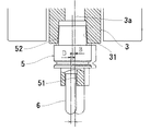
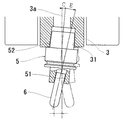
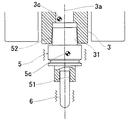
図3(a)に示すように、工具ホルダ5は回転軸を中心とした回転体形状を成し、工具ホルダ5の先端部には工具6を嵌合して装着する工具クランプ部51が形成され、工具ホルダ5の後端部には主軸3の主軸テーパー部31に嵌合して主軸3に装着されるホルダテーパー部52が形成されている。
As shown in FIG. 3A, the
本願の発明者らは、工作機械1における工具6の先端振れの主な要因を以下の4つに分類し、これらの振れが最小となるような主軸3に対する工具ホルダ5の位相を自動的に検出することにより、工具6又は回転系Rの振れが最も小さくなる位相で工具ホルダ5を自動的に装着することができると考えた。
The inventors of the present application classify the main causes of the tip deflection of the
工作機械1において、低速回転領域を含む主軸3の回転時における工具6の先端振れが発生する個別の要素としては、主軸3に起因するものとして、
(A)主軸中心の振れ回り(主軸の軸受回転精度などによる自転・公転軸のズレ)
(B)主軸中心と主軸テーパー部の芯ズレ
(C)主軸中心と主軸テーパー部の角度差
が挙げられ、工具ホルダ5に起因するものとして、
(D)ホルダテーパー部と工具クランプ部の芯ズレ
(E)ホルダテーパー部と工具クランプ部の角度差
が挙げられ、工具6に起因するものとして、
(F)工具の形状精度
が挙げられる。これら個別要素の組み合わせとして、主軸3の低速・高速回転時における工具6の先端振れの主な要因は以下の3つに分類される。
In the
(A) Swing around the main spindle (deviation of rotation and revolution axes due to the bearing rotation accuracy of the main spindle, etc.)
(B) Misalignment between the main spindle center and the main spindle taper portion (C) The angular difference between the main spindle center and the main spindle taper portion may be mentioned, which is attributed to the
(D) Misalignment between the holder taper portion and the tool clamp portion (E) The angular difference between the holder taper portion and the tool clamp portion can be mentioned, and the cause of the
(F) The shape accuracy of the tool can be mentioned. As a combination of these individual elements, the main factors of the tip deflection of the
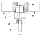
図3(a)に示すように、主軸3の回転軸3aである主軸中心と、主軸テーパー部31の形状中心である主軸テーパー中心が完全に一致しないことによる主軸中心と主軸テーパー部の芯ズレ(B)が生じる。また、工具ホルダ5において、ホルダテーパー部52の形状中心と工具クランプ部51の形状中心が完全に一致しないことによるホルダテーパー部と工具クランプ部の芯ズレ(D)が生じる。この主軸中心と主軸テーパー部の芯ズレ(B)と、ホルダテーパー部と工具クランプ部の芯ズレ(D)との組み合わせによって、工具6の先端振れが発生する。図3(a)に示すように、芯ズレ(B)と芯ズレ(D)が重畳される位相で工具ホルダ5が主軸3に装着されると工具6の先端振れが最大となり、図3(b)に示すように、芯ズレ(B)と芯ズレ(D)が打ち消し合う位相で工具ホルダ5が主軸3に装着されると工具6の先端振れが最小となる。なお、各ズレの大きさは、説明のために拡大して描画している。
As shown in FIG. 3A, the misalignment between the main spindle center and the main spindle taper portion due to the main spindle center, which is the
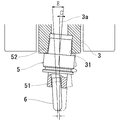
図4(a)に示すように、主軸3の回転軸3aである主軸中心と、主軸テーパー部31の形状中心である主軸テーパー中心の方向が完全に一致しないことによる主軸中心と主軸テーパー部の角度差(C)が生じる。また、工具ホルダ5において、ホルダテーパー部52の形状中心と工具クランプ部51の形状中心の方向が完全に一致しないことによるホルダテーパー部と工具クランプ部の角度差(E)が生じる。この主軸中心と主軸テーパー部の角度差(C)と、ホルダテーパー部と工具クランプ部の角度差(E)との組み合わせによって、工具6の先端振れが発生する。図4(a)に示すように、角度差(C)と角度差(E)が重畳される位相で工具ホルダ5が主軸3に装着されると工具6の先端振れが最大となり、図4(b)に示すように、角度差(C)と角度差(E)が打ち消し合う位相で工具ホルダ5が主軸3に装着されると工具6の先端振れが最小となる。
As shown in FIG. 4 (a), the main spindle center and main spindle taper section are obtained because the direction of the main spindle center which is the
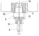
図5(a)に示すように、主軸3の回転軸3aと主軸中心が完全に一致しないことによる主軸中心の振れ回り(A)が生じる。また、工具6において、工具の形状精度によるズレ(F)が生じる。この主軸中心の振れ回り(A)と、工具の形状精度によるズレ(F)との組み合わせによって、工具6の先端振れが発生する。図5(a)に示すように、主軸中心の振れ回り(A)と工具の形状精度によるズレ(F)が重畳される位相で工具ホルダ5が主軸3に装着されると工具6の先端振れが最大となり、図5(b)に示すように、主軸中心の振れ回り(A)と工具の形状精度によるズレ(F)が打ち消し合う位相で工具ホルダ5が主軸3に装着されると工具6の先端振れが最小となる。
As shown in FIG. 5 (a), a swing (A) of the spindle center occurs due to the
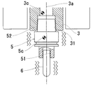
上記の主軸3の低速・高速回転時における工具6の先端振れに加えて、主軸3の高速回転時には、主軸3、工具ホルダ5及び工具6で構成される回転系Rのアンバランスによる遠心力の影響が大きくなり、全体の振れ回り量が増大する。回転系Rのアンバランスの要因としては、上記(A)〜(F)の形状的な精度の他に、主軸3、工具ホルダ5又は工具6の材料不均一などが影響し、工具6の先端振れが発生する。図6(a)に示すように、主軸3の回転軸3aに対する主軸3の重心3cのズレと工具ホルダ5及び工具6の重心5cのズレが重畳される位相で工具ホルダ5が主軸3に装着されるとアンバランスが最大となり、主軸3の振動の原因となる。一方、図6(b)に示すように、主軸3の回転軸3aに対する主軸3の重心3cのズレと工具ホルダ5及び工具6の重心5cのズレが打ち消し合う位相で工具ホルダ5が主軸3に装着されるとアンバランスが最小となる。
In addition to the deflection of the tip of the
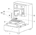
図1は、本発明に係る工作機械1の一実施例を示す斜視図である。
図1に示す実施例において、工作機械1はマシニングセンタであり、ワークを載置するテーブル2と、工具6を装着した工具ホルダ5を装着する主軸3と、主軸3を回転自在に支持する主軸ハウジング4と、を有する。テーブル2は、X軸方向及びY軸方向に駆動され、主軸ハウジング4はZ軸方向に駆動される。工作機械1は、主軸3の先端に工具ホルダ5を介して工具6が装着され、工具6を回転させながらワークに対してX,Y,Z軸方向に相対移動させ、ワークを所望の形状に加工する。また、工作機械1は、図示しないが、工具6の加工軌跡を数値制御する制御装置と、加工条件、工具交換、座標設定などの指示を入力する操作パネルと、加工情報や位置情報などを表示するモニターを備えている。なお、工作機械1は、図示の立形マシニングセンタに限られず、横形マシニングセンタの他、ボール盤、中ぐり盤、フライス盤、研削盤など各種の工作機械に本発明を適用することが可能である。
FIG. 1 is a perspective view showing an embodiment of a
In the embodiment shown in FIG. 1, the
工作機械1は、主軸3の回転時に、主軸3の回転軸3aに対する主軸3、工具ホルダ5及び工具6で構成される回転系Rの振れを測定する振れセンサ10と、工具ホルダ5を主軸3に対して異なる位相で装着する位相制御機構と、を有している。位相制御機構は、制御装置によって制御され、主軸3の割り出し機能を利用して主軸3に対する工具ホルダ5の位相を制御する。位相制御機構は、二以上の異なる位相において測定した回転系Rの振れを比較し、該振れが最小となる位相で工具ホルダ5を主軸3に装着する振れ修正機構を備えている。
The
工作機械1は、工具6を装着した工具ホルダを主軸3に着脱させる着脱機構7を備えている。着脱機構7は、ATC(Auto Tool Changer)フィンガーなどで構成され、図示しないが、主軸3から取り外した工具ホルダ5を収容する工具マガジンを備えている。また、工作機械1は、位相制御機構を着脱機構7に設けてもよく、主軸3が割り出し機能を備えていない場合でも、工具ホルダ5を主軸3に対して異なる位相で装着することができる。位相制御機構は、例えばATCフィンガーに設けることができる。
The
位相制御機構は、着脱機構7が工具ホルダ5を把持して主軸3から取り外したときに、回転系Rの振れを測定する回数Nで360°を等分した所定角度(360°/N)だけ一定方向に主軸3を回転させ、着脱機構7が工具ホルダ5を主軸3に装着したときに、主軸3に対する工具ホルダ5の位相を所定角度(360°/N)だけ変えることができる。なお、工具ホルダ5が位置決めキーを有する場合には、前記所定角度は180°(N=2)となる。工具ホルダ5が位置決めキーを有さない場合は、測定回数Nを2以上の任意の自然数に設定することができる。
In the phase control mechanism, when the attaching /
工作機械1は、振れセンサ10として、レーザセンサや画像センサなどによって工具6の振れを直接的に測定する光学センサ11と、加速度センサ、振動センサや音響センサなどによって主軸3の振動を測定する振動センサ12と、を備えている。図1に示す実施例において、光学センサ11はレーザセンサであり、テーブル2上の加工の妨げにならない場所に設置している。光学センサ11は、主軸3の停止時及び回転時に工具6をセンサ間の直交する方向に移動させて工具6の両側端を検出し、停止時と回転時の幅を比較することにより、回転時の工具6の振れ幅を検出する。光学センサ11は、加工精度に影響を与える工具6の先端部の振れを検出することが好ましい。図3乃至図6に示すように、工具6がボールエンドミルである場合には、先端のボール部の中心位置での振れを検出することが好ましい。
The
振動センサ12は、主軸ハウジング4に設置され、主軸3の振動を加速度、振幅の大きさ、音の大きさなどで測定する。振動センサ12の設置場所は、図1に示すように、主軸ハウジング4の表面に限らず、主軸ハウジング4の内部に設置してもよい。13は、Z軸方向の位置を検出する機械軸スケールであり、この機械軸スケールに振動検出機能を設けてもよい。振れセンサ10は、少なくとも光学センサ11を備えていることが好ましく、振動センサ12の他、複数の光学センサを備えていてもよい。
The vibration sensor 12 is installed in the spindle housing 4 and measures the vibration of the
振れ修正機構は、工具6の振れ及び主軸3の振動に許容値を設定してもよい。実施例において、振れ修正機構は、光学センサ11で測定した工具6の振れが最小となる位相と振動センサ12で測定した主軸3の振動が最小となる位相が異なる場合に、工具6の振れ及び主軸3の振動の双方が許容範囲内であるか否かを判断し、一の位相のみが該条件を満たすときには該位相を回転系Rの振れが最小となる位相であると判断し、何れの位相も該条件を満たす又は何れの位相も該条件を満たさないときには工具6の振れが最小となる位相を回転系Rの振れが最小となる位相であると判断する。また、振れ修正機構は、振動センサ12で測定した主軸3の振動が許容値に収まる各位相において、光学センサ11で測定した工具6の振れが最小となる位相を回転系Rの振れが最小となる位相であると判断してもよい。
The shake correction mechanism may set allowable values for the shake of the
また、振れ修正機構は、測定した回転系Rの振れに基づいて主軸3の回転軸3aに対する工具ホルダ5及び工具6の偏芯方向を割り出し、回転系Rの振れが最小となる位相を予測する手段を備えていることが好ましい。振れ修正機構は、二以上の異なる位相において測定した回転系Rの振れを比較して該振れが最小となる位相を判断又は予測する第一の測定手段と、第一の測定手段で振れが最小であると判断又は予測した位相を含む所定角度の範囲を第一の測定手段より細かい位相差で二以上の異なる位相において回転系Rの振れを測定し、該振れを比較して該振れが最小となる位相で工具ホルダ5を主軸3に装着する第二の測定手段と、を備えた構成にすることもできる。
The shake correction mechanism also determines the eccentric direction of the
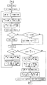
次に、本発明に係る工作機械1を用いた工具6の振れ修正方法について説明する。図2は、本発明に係る振れ修正方法の一実施例を示すフローチャートである。工具6の振れ修正方法は、工具ホルダ5を主軸3に対して二以上の異なる位相で装着し、それぞれの位相において工具6の振れを含む回転系Rの振れを測定する振れ測定工程と、それぞれの位相において測定した回転系Rの振れを比較する振れ比較工程と、回転系Rの振れが最小となる位相で工具ホルダ5を主軸3に装着する振れ修正工程と、を有する。
Next, a method of correcting runout of the
(1)制御装置は、工具6の振れを含む回転系Rの振れを測定する全計測回数をN(Nは2以上の自然数)に設定する。全計測回数は予め決められた回数に設定してもよく、操作者に回数の設定を求めてもよい。制御装置は、計測回(n)、主軸3の位相(angle)及び振れ・振動の大きさ(data)を初期値(0)に設定する。
(1) The control device sets the total number of measurements for measuring the shake of the rotary system R including the shake of the
(2)制御装置は、主軸3の位相(angle)が360°×n/Nとなる角度に主軸3の割り出しを行う。着脱機構7は、ATCフィンガーが工具マガジンから所望の工具6を装着した工具ホルダ5を取り出し、工具ホルダ5を主軸に装着する。ATCフィンガー及び工具マガジンが主軸3から退避すると、振れセンサ10が工具6の振れ及び主軸3の振動を測定する。
(2) The control device indexes the
(3)制御装置は、計測回(n)が初期値(0)のとき、振れセンサ10が測定した計測値を振れ・振動の大きさ(data)として入力する。制御装置は、計測回(n)が初期値(0)以外のとき、振れセンサ10が測定した計測値と、振れ・振動の大きさとして既に入力されている値(data)とを比較し、計測値が小さいときには該計測値を振れ・振動の大きさ(data)として主軸3の位相(angle=360°×n/N)と共に上書きして入力する。一方、計測値が、振れ・振動の大きさとして既に入力されている値(data)と同じか大きいときには、制御装置はdataとして入力しない。
(3) When the number of measurements (n) is the initial value (0), the control device inputs the measured value measured by the
(4)制御装置は、計測回(n)に「1」を加え、計測回(n)と全計測回数Nとを比較する。 (4) The control device adds “1” to the number of measurements (n) and compares the number of measurements (n) with the total number of measurements N.
(5)計測回(n)が全計測回数Nに達していないとき、着脱機構7は、ATCフィンガー及び工具マガジンを主軸3へ移動させ、ATCフィンガーが主軸3から工具ホルダ5を取り外し、該工具ホルダ5を工具マガジンに移動させる。ATCフィンガー及び工具マガジンが主軸3から退避して、上記(2)以降の工程を繰り返す。
(5) When the number of times of measurement (n) has not reached the total number of times of measurement N, the attaching /
(6)計測回(n)が全計測回数Nに達したとき、制御装置は、主軸3の位相(angle)として入力されている角度が360°×(n−1)/Nであるときには、回転系Rの振れが最小となる位相で工具ホルダ5が主軸3に装着されていると判断し、主軸3への工具6の装着を終了する。
(6) When the number of times of measurement (n) reaches the total number of times of measurement N, when the angle input as the phase (angle) of the
(7)計測回(n)が全計測回数Nに達したとき、制御装置が主軸3の位相(angle)として入力されている角度が360°×(n−1)/Nでないと判断したときには、着脱機構7は、ATCフィンガー及び工具マガジンを主軸3へ移動させ、ATCフィンガーが主軸3から工具ホルダ5を取り外し、該工具ホルダ5を工具マガジンに移動させる。ATCフィンガー及び工具マガジンが主軸3から退避すると、制御装置は、回転系Rの振れが最小となる主軸3の位相(angle)として入力されている角度に主軸3の割り出しを行う。着脱機構7は、ATCフィンガーが工具マガジンから工具ホルダ5を取り出し、回転系Rの振れが最小となる位相で工具ホルダ5を主軸に装着する。ATCフィンガー及び工具マガジンが主軸3から退避して、主軸3への工具6の装着を終了する。
(7) When the number of times of measurement (n) reaches the total number of times of measurement N, when the controller determines that the angle input as the phase (angle) of the
本発明の振れ修正方法は、上記(1)〜(7)の工程によって、主軸3と工具ホルダ5の関係において工具6又は回転系Rの振れ又は振動が最小になる工具ホルダ5の位相を自動的に検出することができ、工具6又は回転系Rの振れ又は振動が最も小さくなる位相で工具ホルダ5を自動的に装着することができる。
In the shake correction method of the present invention, the phase of the
本発明の振れ修正方法は、振れ比較工程が、それぞれの位相において測定した回転系Rの振れを予め定めた振れの許容値と比較する工程を備え、振れ修正工程が、回転系Rの振れ又は振動が該許容値以下になった位相で工具ホルダ5を主軸3に装着する構成にしてもよい。また、発明の振れ修正方法は、工具3の振れと主軸3の振動が共に許容値以下になった位相で工具ホルダ5を主軸3に装着するようにしてもよく、工具3の振れと主軸3の振動に優先順位をつける又は重み付けをして位相を決定するようにしてもよい。
The shake correction method according to the present invention includes the step of comparing the shake of the rotation system R measured at each phase with a predetermined tolerance of shake, and the shake correction process includes the shake of the rotation system R or The
本発明の振れ修正方法は、振れ比較工程が、それぞれの位相において測定した回転系Rの振れを予め定めた振れの許容値と比較する工程を備え、該工程で比較した回転系Rの振れが全ての位相において該許容値を上回った場合に、工具ホルダ5から工具6を取り外し、工具ホルダ5に対して工具6の位相を変えて該工具6を装着する工具位相変更工程を有し、回転系Rの振れが該許容値以下になるまで工具位相変更工程と、振れ測定工程と、振れ比較工程と、を繰り返す構成にしてもよい。工具位相変更工程は、機械で工具6の位相を変えるものでもよく、人手で工具6の位相を変えるものでもよい。
The shake correction method of the present invention includes the step of comparing the shake of the rotating system R measured in each phase with the predetermined allowable value of the shake in the shake comparison step, and the shake of the rotating system R compared in the step is A tool phase changing process of removing the
1 工作機械
2 テーブル
3 主軸
3a 回転軸
4 主軸ハウジング
5 工具ホルダ
6 工具
7 着脱機構
10 振れセンサ
11 光学センサ
12 振動センサ
Claims (6)
前記主軸の回転時に前記工具の振れを測定する光学センサ及び前記主軸の振動を測定する振動センサを含み、前記主軸の回転軸に対する前記主軸、前記工具ホルダ及び前記工具で構成される回転系の振れを測定する振れセンサと、
前記工具ホルダを前記主軸に対して異なる位相で装着する位相制御機構と、を有し、
前記位相制御機構が、二以上の異なる位相において測定した前記回転系の振れを比較し、該振れが最小となる位相で前記工具ホルダを前記主軸に装着する振れ修正機構を備え、
前記光学センサで測定した前記工具の振れが最小となる位相と前記振動センサで測定した前記主軸の振動が最小となる位相が異なる場合に、
前記振れ修正機構は、前記工具の振れ及び前記主軸の振動の双方が許容範囲内であるか否かを判断し、一の位相のみが該条件を満たすときには該位相を前記回転系の振れが最小となる位相であると判断し、何れの位相も該条件を満たす又は何れの位相も該条件を満たさないときには前記工具の振れが最小となる位相を前記回転系の振れが最小となる位相であると判断することを特徴とする工作機械。 A machine tool comprising a mounting and demounting mechanism for automatically mounting and demounting a tool holder equipped with a tool on a spindle,
A swing of a rotation system including the spindle, the tool holder, and the tool with respect to the rotation axis of the spindle including an optical sensor that measures the swing of the tool when the spindle rotates and a vibration sensor that measures the vibration of the spindle. Shake sensor to measure
A phase control mechanism for mounting the tool holder in different phases with respect to the spindle;
The phase control mechanism comprises a shake correction mechanism for comparing the swings of the rotary system measured at two or more different phases and mounting the tool holder on the spindle at a phase at which the swing is minimized ,
When the phase in which the tool shake measured by the optical sensor is the smallest and the phase in which the vibration of the spindle measured by the vibration sensor is the smallest differ from each other.
The runout correction mechanism determines whether both the runout of the tool and the vibration of the spindle are within an allowable range, and when only one phase satisfies the condition, the runout of the rotation system is minimized. It is determined that the phase is such that any phase satisfies the condition or any phase does not satisfy the condition is a phase at which the swing of the tool is minimized by a phase at which the swing of the rotation system is minimized. A machine tool that is characterized by
前記主軸の回転時に、前記主軸の回転軸に対する前記主軸、前記工具ホルダ及び前記工具で構成される回転系の振れを測定する振れセンサと、A shake sensor that measures a shake of a rotation system including the spindle, the tool holder, and the tool with respect to the rotation axis of the spindle when the spindle rotates;
前記工具ホルダを前記主軸に対して異なる位相で装着する位相制御機構と、を有し、A phase control mechanism for mounting the tool holder in different phases with respect to the spindle;
前記位相制御機構が、二以上の異なる位相において測定した前記回転系の振れを比較し、該振れが最小となる位相で前記工具ホルダを前記主軸に装着する振れ修正機構を備え、The phase control mechanism comprises a shake correction mechanism for comparing the swings of the rotary system measured at two or more different phases and mounting the tool holder on the spindle at a phase at which the swing is minimized,
前記振れ修正機構が、二以上の異なる位相において測定した前記回転系の振れを比較して該振れが最小となる位相を判断又は予測する第一の測定手段と、前記第一の測定手段で前記振れが最小であると判断又は予測した位相を含む所定角度の範囲を前記第一の測定手段より細かい位相差で二以上の異なる位相において前記回転系の振れを測定し、該振れを比較して該振れが最小となる位相で前記工具ホルダを前記主軸に装着する第二の測定手段と、を備えた工作機械。A first measurement means for comparing the shake of the rotation system measured at two or more different phases and determining or predicting a phase at which the shake is minimized; and The range of a predetermined angle including the phase determined or predicted to have a minimum shake is measured with two or more different phases with a finer phase difference than the first measuring means, and the shake is compared A second measuring means for mounting the tool holder on the spindle at a phase at which the runout is minimized.
前記主軸の回転時に、前記主軸の回転軸に対する前記主軸、前記工具ホルダ及び前記工具で構成される回転系の振れとして、前記工具の振れを測定する振れセンサと、A shake sensor that measures a shake of the tool as a shake of a rotation system including the spindle, the tool holder, and the tool with respect to the rotation axis of the spindle when the spindle rotates;
前記工具ホルダを前記主軸に対して異なる位相で装着する位相制御機構と、を有し、A phase control mechanism for mounting the tool holder in different phases with respect to the spindle;
前記位相制御機構が、二以上の異なる位相において測定した前記工具の振れを比較し、該振れが最小となる位相で前記工具ホルダを前記主軸に装着する振れ修正機構を備え、The phase control mechanism comprises a runout correction mechanism that compares the runouts of the tool measured at two or more different phases and mounts the tool holder on the main spindle at a phase at which the runout is minimized.
前記振れ修正機構が、測定した前記工具の振れに基づいて前記主軸の回転軸に対する前記工具の偏芯方向を割り出し、前記工具の振れが最小となる位相を予測する手段を備えた工作機械。A machine tool comprising: means for determining the eccentricity direction of the tool with respect to the rotation axis of the spindle based on the measured deflection of the tool, and predicting a phase at which the deflection of the tool is minimized.
前記主軸の回転時に、前記主軸の回転軸に対する前記主軸、前記工具ホルダ及び前記工具で構成される回転系の振れを測定する振れセンサと、
前記工具ホルダを前記主軸に対して異なる位相で装着する位相制御機構と、を有する工作機械を用いた工具の振れ又は/及び前記主軸の振動の修正方法であって、
前記工具ホルダを前記主軸に対して二以上の異なる位相で装着し、それぞれの位相において前記回転系の振れを測定する振れ測定工程と、
それぞれの位相において測定した前記回転系の振れを比較する振れ比較工程と、
前記回転系の振れが最小となる位相で前記工具ホルダを前記主軸に装着する振れ修正工程と、を有し、
前記比較工程が、前記測定工程において最初に測定した計測値を位相と共に記憶する工程と、前記測定工程において異なる位相で測定した計測値を記憶されている前記計測値と比較し、測定した該計測値が記憶されている前記計測値より小さいときに測定した該計測値を位相と共に置き換えて記憶する工程と、を備え、
前記測定工程と前記比較工程を所定回数繰り返したときに、計測値と共に記憶されている位相を前記回転系の振れが最小となる位相であると判断する振れ修正方法。 Equipped with an attachment / detachment mechanism for automatically attaching / detaching a tool holder equipped with a tool to / from the spindle
A shake sensor that measures a shake of a rotation system including the spindle, the tool holder, and the tool with respect to the rotation axis of the spindle when the spindle rotates;
And a phase control mechanism for mounting the tool holder in different phases with respect to the spindle, wherein the method for correcting the swing of the tool or / and the vibration of the spindle using a machine tool,
A runout measuring step of mounting the tool holder at two or more different phases with respect to the main spindle and measuring a runout of the rotation system at each phase;
A swing comparison step of comparing the swing of the rotation system measured at each phase;
Have a, a shake correction process is mounted on the spindle of the tool holder in the rotating system deflection of the minimum phase,
The comparison step stores the measurement value measured first in the measurement step together with the phase, and the measurement value measured by comparing the measurement value measured with a different phase in the measurement step with the stored measurement value Replacing the measured value measured when the value is smaller than the stored measured value with the phase and storing the phase value;
A shake correction method, which determines that the phase stored together with the measurement value is a phase that minimizes the shake of the rotation system when the measurement process and the comparison process are repeated a predetermined number of times .
該工程で比較した前記回転系の振れが全ての位相において前記許容値を上回った場合に、前記工具ホルダから前記工具を取り外し、前記工具ホルダに対して前記工具の位相を変えて該工具を装着する工具位相変更工程を有し、
前記回転系の振れが前記許容値以下になるまで前記工具位相変更工程と、前記振れ測定工程と、前記振れ比較工程と、を繰り返すことを特徴とする請求項5に記載の振れ修正方法。 The swing comparison step comprising the step of comparing the swing of the rotary system measured at each phase with a predetermined swing tolerance value;
The tool is removed from the tool holder when the swing of the rotary system compared in the step exceeds the allowable value in all phases, and the tool is mounted with the tool phase changed with respect to the tool holder. Tool phase change process to
The shake correction method according to claim 5 , wherein the tool phase changing step, the shake measurement step, and the shake comparison step are repeated until the shake of the rotation system becomes equal to or less than the allowable value.
Priority Applications (1)
| Application Number | Priority Date | Filing Date | Title |
|---|---|---|---|
| JP2015124945A JP6532769B2 (en) | 2015-06-22 | 2015-06-22 | Runout correction method for machine tools and tools |
Applications Claiming Priority (1)
| Application Number | Priority Date | Filing Date | Title |
|---|---|---|---|
| JP2015124945A JP6532769B2 (en) | 2015-06-22 | 2015-06-22 | Runout correction method for machine tools and tools |
Publications (2)
| Publication Number | Publication Date |
|---|---|
| JP2017007030A JP2017007030A (en) | 2017-01-12 |
| JP6532769B2 true JP6532769B2 (en) | 2019-06-19 |
Family
ID=57761040
Family Applications (1)
| Application Number | Title | Priority Date | Filing Date |
|---|---|---|---|
| JP2015124945A Active JP6532769B2 (en) | 2015-06-22 | 2015-06-22 | Runout correction method for machine tools and tools |
Country Status (1)
| Country | Link |
|---|---|
| JP (1) | JP6532769B2 (en) |
Families Citing this family (10)
| Publication number | Priority date | Publication date | Assignee | Title |
|---|---|---|---|---|
| JP6549646B2 (en) | 2017-07-06 | 2019-07-24 | ファナック株式会社 | Machine tool and home position correction method |
| JP6452898B1 (en) * | 2017-10-25 | 2019-01-16 | 三菱電機株式会社 | Spindle unit runout detector |
| JP6615285B1 (en) * | 2018-07-20 | 2019-12-04 | 株式会社牧野フライス製作所 | Tool runout adjustment method and machine tool |
| CN111716149B (en) | 2019-03-19 | 2024-07-30 | 发那科株式会社 | Machine tool |
| JP7424759B2 (en) * | 2019-05-23 | 2024-01-30 | ファナック株式会社 | Spindle abnormality detection device |
| EP4552774B1 (en) * | 2019-08-09 | 2026-03-25 | Sumitomo Electric Industries, Ltd. | Rotating tool, module and cutting system |
| GB201914730D0 (en) * | 2019-10-11 | 2019-11-27 | Renishaw Plc | Apparatus and method |
| JP6868147B1 (en) * | 2020-08-04 | 2021-05-12 | Dmg森精機株式会社 | Machine tools, detection methods, and detection programs |
| JP7814139B2 (en) * | 2021-10-20 | 2026-02-16 | 芝浦機械株式会社 | Tool measuring device and tool measuring method |
| CN114273971B (en) * | 2021-12-09 | 2023-04-25 | 山东有荣机床有限公司 | Milling cutter correcting device for multi-axis machining center |
Family Cites Families (3)
| Publication number | Priority date | Publication date | Assignee | Title |
|---|---|---|---|---|
| JP2961612B2 (en) * | 1989-07-04 | 1999-10-12 | 豊田工機株式会社 | Tool mounting device |
| JP3377665B2 (en) * | 1995-12-15 | 2003-02-17 | 新潟県 | Cutting method of fibrous organic material, hard brittle inorganic material, vitreous inorganic material by end mill tool |
| JP2015051494A (en) * | 2013-09-09 | 2015-03-19 | 東芝機械株式会社 | Tool installation method |
-
2015
- 2015-06-22 JP JP2015124945A patent/JP6532769B2/en active Active
Also Published As
| Publication number | Publication date |
|---|---|
| JP2017007030A (en) | 2017-01-12 |
Similar Documents
| Publication | Publication Date | Title |
|---|---|---|
| JP6532769B2 (en) | Runout correction method for machine tools and tools | |
| US9511464B2 (en) | Adjustment mechanism for rotation runout and dynamic balance of rotating tool | |
| JP5962242B2 (en) | Grinding equipment | |
| JP6921511B2 (en) | Machine tools with automatic tool changer and automatic measurement method | |
| JP2017154202A (en) | Processing method and processing device by end mill | |
| TWI781353B (en) | Machine tools and controls | |
| CN112334748A (en) | Method for determining the position of the mass and the center of gravity of a load in a mobile system, especially a machine tool | |
| JP2020011366A (en) | Method for adjusting deflection of tool and machine tool | |
| WO2020203844A1 (en) | Industrial machine, eccentricity specifying device, eccentricity specifying method, and program | |
| US20140354267A1 (en) | Method of compensating command value for rotation angle | |
| EP1803530A2 (en) | Tool displacement controlling and correcting device for machine tool | |
| JP5170517B2 (en) | Apparatus and method for correcting rotation balance of rotating body | |
| CN111506015A (en) | Method for determining the shape of a machine tool surface | |
| JP4415680B2 (en) | Grinding apparatus and grinding method | |
| WO2019082302A1 (en) | Spindle unit center runout detection apparatus | |
| JP3540634B2 (en) | Processing device using rotary positioning device and tool | |
| KR102864295B1 (en) | Apparatus and method for correcting unbalance of rotating workpiece | |
| CN111376106B (en) | Origin detection method for machine tool and tool library | |
| JP4940904B2 (en) | Bulk quantity measuring device | |
| JP2009291915A (en) | Machine tool | |
| JP4609237B2 (en) | Unbalance correction method and apparatus | |
| JP7514800B2 (en) | Machine tool and method for aligning machine tool axis | |
| CN113093644A (en) | Control device, operation system, and recording medium having program recorded thereon | |
| JP7828266B2 (en) | Groove grinding method, groove grinding device, and program | |
| JP7590808B2 (en) | Balancing device and method for a rotating body |
Legal Events
| Date | Code | Title | Description |
|---|---|---|---|
| A621 | Written request for application examination |
Free format text: JAPANESE INTERMEDIATE CODE: A621 Effective date: 20180319 |
|
| A977 | Report on retrieval |
Free format text: JAPANESE INTERMEDIATE CODE: A971007 Effective date: 20181213 |
|
| A131 | Notification of reasons for refusal |
Free format text: JAPANESE INTERMEDIATE CODE: A131 Effective date: 20181218 |
|
| A521 | Request for written amendment filed |
Free format text: JAPANESE INTERMEDIATE CODE: A523 Effective date: 20190215 |
|
| TRDD | Decision of grant or rejection written | ||
| A01 | Written decision to grant a patent or to grant a registration (utility model) |
Free format text: JAPANESE INTERMEDIATE CODE: A01 Effective date: 20190521 |
|
| A61 | First payment of annual fees (during grant procedure) |
Free format text: JAPANESE INTERMEDIATE CODE: A61 Effective date: 20190522 |
|
| R150 | Certificate of patent or registration of utility model |
Ref document number: 6532769 Country of ref document: JP Free format text: JAPANESE INTERMEDIATE CODE: R150 |
|
| R250 | Receipt of annual fees |
Free format text: JAPANESE INTERMEDIATE CODE: R250 |
|
| R250 | Receipt of annual fees |
Free format text: JAPANESE INTERMEDIATE CODE: R250 |