JP6532725B2 - Disposable Wearables - Google Patents

Disposable Wearables Download PDF

Info

Publication number
JP6532725B2
JP6532725B2 JP2015064328A JP2015064328A JP6532725B2 JP 6532725 B2 JP6532725 B2 JP 6532725B2 JP 2015064328 A JP2015064328 A JP 2015064328A JP 2015064328 A JP2015064328 A JP 2015064328A JP 6532725 B2 JP6532725 B2 JP 6532725B2
Authority
JP
Japan
Prior art keywords
area
proximal portion
display element
tape tab
display
Prior art date
Legal status (The legal status is an assumption and is not a legal conclusion. Google has not performed a legal analysis and makes no representation as to the accuracy of the status listed.)
Active
Application number
JP2015064328A
Other languages
Japanese (ja)
Other versions
JP2016182257A (en
Inventor
克文 青木
克文 青木
瀧野 俊介
俊介 瀧野
Current Assignee (The listed assignees may be inaccurate. Google has not performed a legal analysis and makes no representation or warranty as to the accuracy of the list.)
Uni Charm Corp
Original Assignee
Uni Charm Corp
Priority date (The priority date is an assumption and is not a legal conclusion. Google has not performed a legal analysis and makes no representation as to the accuracy of the date listed.)
Filing date
Publication date
Application filed by Uni Charm Corp filed Critical Uni Charm Corp
Priority to JP2015064328A priority Critical patent/JP6532725B2/en
Priority to PCT/JP2016/051307 priority patent/WO2016152209A1/en
Publication of JP2016182257A publication Critical patent/JP2016182257A/en
Application granted granted Critical
Publication of JP6532725B2 publication Critical patent/JP6532725B2/en
Active legal-status Critical Current
Anticipated expiration legal-status Critical

Links

Images

Classifications

    • AHUMAN NECESSITIES
    • A61MEDICAL OR VETERINARY SCIENCE; HYGIENE
    • A61FFILTERS IMPLANTABLE INTO BLOOD VESSELS; PROSTHESES; DEVICES PROVIDING PATENCY TO, OR PREVENTING COLLAPSING OF, TUBULAR STRUCTURES OF THE BODY, e.g. STENTS; ORTHOPAEDIC, NURSING OR CONTRACEPTIVE DEVICES; FOMENTATION; TREATMENT OR PROTECTION OF EYES OR EARS; BANDAGES, DRESSINGS OR ABSORBENT PADS; FIRST-AID KITS
    • A61F13/00Bandages or dressings; Absorbent pads
    • A61F13/15Absorbent pads, e.g. sanitary towels, swabs or tampons for external or internal application to the body; Supporting or fastening means therefor; Tampon applicators
    • A61F13/45Absorbent pads, e.g. sanitary towels, swabs or tampons for external or internal application to the body; Supporting or fastening means therefor; Tampon applicators characterised by the shape
    • A61F13/49Absorbent articles specially adapted to be worn around the waist, e.g. diapers
    • A61F13/496Absorbent articles specially adapted to be worn around the waist, e.g. diapers in the form of pants or briefs
    • AHUMAN NECESSITIES
    • A61MEDICAL OR VETERINARY SCIENCE; HYGIENE
    • A61FFILTERS IMPLANTABLE INTO BLOOD VESSELS; PROSTHESES; DEVICES PROVIDING PATENCY TO, OR PREVENTING COLLAPSING OF, TUBULAR STRUCTURES OF THE BODY, e.g. STENTS; ORTHOPAEDIC, NURSING OR CONTRACEPTIVE DEVICES; FOMENTATION; TREATMENT OR PROTECTION OF EYES OR EARS; BANDAGES, DRESSINGS OR ABSORBENT PADS; FIRST-AID KITS
    • A61F13/00Bandages or dressings; Absorbent pads
    • A61F13/15Absorbent pads, e.g. sanitary towels, swabs or tampons for external or internal application to the body; Supporting or fastening means therefor; Tampon applicators
    • A61F13/551Packaging before or after use
    • AHUMAN NECESSITIES
    • A61MEDICAL OR VETERINARY SCIENCE; HYGIENE
    • A61FFILTERS IMPLANTABLE INTO BLOOD VESSELS; PROSTHESES; DEVICES PROVIDING PATENCY TO, OR PREVENTING COLLAPSING OF, TUBULAR STRUCTURES OF THE BODY, e.g. STENTS; ORTHOPAEDIC, NURSING OR CONTRACEPTIVE DEVICES; FOMENTATION; TREATMENT OR PROTECTION OF EYES OR EARS; BANDAGES, DRESSINGS OR ABSORBENT PADS; FIRST-AID KITS
    • A61F13/00Bandages or dressings; Absorbent pads
    • A61F13/15Absorbent pads, e.g. sanitary towels, swabs or tampons for external or internal application to the body; Supporting or fastening means therefor; Tampon applicators
    • A61F13/56Supporting or fastening means

Landscapes

  • Health & Medical Sciences (AREA)
  • Epidemiology (AREA)
  • Engineering & Computer Science (AREA)
  • Biomedical Technology (AREA)
  • Heart & Thoracic Surgery (AREA)
  • Vascular Medicine (AREA)
  • Life Sciences & Earth Sciences (AREA)
  • Animal Behavior & Ethology (AREA)
  • General Health & Medical Sciences (AREA)
  • Public Health (AREA)
  • Veterinary Medicine (AREA)
  • Absorbent Articles And Supports Therefor (AREA)

Description

本発明は、使い捨て着用物品に関し、より詳しくは、テープタブを備えた使い捨て着用物品に関する。   The present invention relates to disposable wearing articles, and more particularly, to disposable wearing articles provided with a tape tab.

従来、テープタブを備えた使い捨て着用物品は公知である。例えば、特許文献1には、おむつ本体の前後ウエスト域に複数条のウエスト弾性体が配設されており、前後ウエスト域を連結するシーム部に固定された一対のテープタブを有する使い捨て着用物品が開示されている。一対のテープタブは、フック要素等からなる止着域とそれよりも先端側に位置する摘持部を有する。   In the past, disposable wear articles with tape tabs are known. For example, Patent Document 1 discloses a disposable wearing article having a plurality of waist elastics disposed in the front and rear waist regions of the diaper body and having a pair of tape tabs fixed to the seam portions connecting the front and rear waist regions. It is done. The pair of tape tabs have a fastening area composed of a hook element or the like and a grip located on the tip side of the fastening area.

実開平6−77719号Japanese Utility Model Hei 6-77719

特許文献1に開示の着用物品によれば、着用中にテープタブを使用することによって、ウエスト周りの大きさを調整して種々のサイズの着用者にもフィットさせてずり落ちを防止することができるとともに、着用後に、排泄物を包み込むように着用物品を丸め、テープタブで丸めた状態が維持できるように止着することによって、衛生的に廃棄することができる。   According to the wearing article disclosed in Patent Document 1, by using the tape tab during wearing, the size around the waist can be adjusted to fit even the wearer of various sizes and prevent slippage In addition, after wearing, it can be disposed of hygienically by rolling the wearing article so as to wrap the excrement and fastening so as to maintain the rolled-up state with the tape tab.

かかる着用物品においては、着用物品の外面全体とテープタブ全体が、それらを形成する不織布又はプラスチックフィルム本来の白色であるから、着用物品の着用者/着用補助者は、テープタブを使用する際に一見してテープタブの外形輪郭を視認することができず、テープタブの摘持部を摘持し難い。また、テープタブ全体に着色やデザインを施した場合であっても、テープタブ全体における摘持部の領域範囲や止着域の位置を視認することができないので、指でテープタブの止着域を着用物品の外面に押し当てて止着するときに、押圧するべき範囲を特定することができない。   In such a wearing article, the entire outer surface of the wearing article and the entire tape tab are intrinsically white of the non-woven fabric or plastic film forming them, so the wearer / wearing assistant of the wearing article looks at the use of the tape tab. Therefore, the outer contour of the tape tab can not be visually recognized, and it is difficult to grip the holding portion of the tape tab. In addition, even when the entire tape tab is colored or designed, it is not possible to visually recognize the area range of the holding portion and the position of the fastening area in the entire tape tab, so the fastening area of the tape tab is worn with a finger It is not possible to specify the range to be pressed when pressing against the outer surface of the.

そこで、本発明の課題は、従来の技術の改良であって、摘持が容易であって、止着操作するときの案内となる表示を有するテープタブを備えた使い捨て着用物品の提供に関する。   Therefore, an object of the present invention is an improvement of the prior art, and relates to the provision of a disposable wearing article provided with a tape tab which is easy to hold and has a guide serving as a guide for fastening operation.

本願は、肌当接面及び非肌当接面と、前後ウエスト域の一方である第1ウエスト域と他方である第2ウエスト域と、前記第1及び第2ウエスト域の側縁部どうしが互いに接合された側部シーム域と、前記第1ウエスト域の前記非肌当接面に取り付けられたテープタブとを有する使い捨て着用物品に関する。   The present application includes a skin contact surface and a non-skin contact surface, a first waist region which is one of the front and rear waist regions, a second waist region which is the other, and side edges of the first and second waist regions. A disposable worn article having a side seam area joined together and a tape tab attached to the non-skin bearing surface of the first waist area.

本願の使い捨て着用物品は、前記テープタブは、厚さ方向と、前記第1ウエスト域の前記非肌当接面に固定された近位部と、前記近位部と前記厚さ方向において対向する遠位部とを有し、前記遠位部は、内面及び外面と、前記内面に位置する止着域と、前記止着域よりも先端側に位置する摘持部とを有し、前記摘持部の前記外面には、第1表示要素を有する第1表示域が位置し、前記止着域の存在する領域の前記外面には、第2表示要素を有する第2表示域が位置しており、前記第1表示要素と前記第2表示要素とは、互いに表示が異なることを特徴とする。   In the disposable wearing article according to the present application, the tape tab has a thickness direction, a proximal portion fixed to the non-skin contact surface of the first waist region, and a distance opposite to the proximal portion in the thickness direction. The distal portion has an inner surface and an outer surface, a fastening area located on the inner surface, and a knob located on the distal side of the fastening area, the knob A first display area having a first display element is located on the outer surface of the part, and a second display area having a second display element is located on the outer surface of the area where the fastening area is present The first display element and the second display element may have different displays.

本発明に係る使い捨て着用物品によれば、テープタブの摘持部の外面に位置する第1表示域と止着域の存在する部分の外面に位置する第2表示域とが、互いに表示の異なる表示要素を有することから、テープタブを使用するとき、
それらの表示域が摘持するべき部分と止着するべき部分とを案内する表示として機能して、止着操作を容易に行うことができる。
According to the disposable wearing article according to the present invention, the first display area located on the outer surface of the holding portion of the tape tab and the second display area located on the outer surface of the portion where the fastening area exists have different displays. When using a tape tab because it has an element,
The display area functions as a display for guiding a portion to be held and a portion to be fixed, so that the fixing operation can be easily performed.

図面は、本発明に係る使い捨て着用物品の特定の実施の形態を示し、発明の不可欠な構成ばかりでなく、選択的及び好ましい実施の形態を含む。
本発明に係る使い捨て着用物品の一例として示す、使い捨てのおむつの正面図。 背面から視たおむつの背面図。 おむつの側部シーム域を剥離して前後方向に伸展した状態をその内面から見た一部破断展開平面図。 おむつの側面図。 図4のV−V線に沿う断面図。 前後ウエスト域が伸長された状態における、図5と同様の断面図。 (a)折り畳まれた状態におけるテープタブの平面図、(b)展開された状態におけるテープタブの平面図。 (a)おむつを廃棄するときに、テープタブを止着操作する様子を示す図、(b)折り畳んだおむつにテープタブを止着した様子を示す図。 実施例の一例に係るおむつの図6と同様の断面図。 他の実施例におけるおむつの背面図。 他の実施例におけるおむつの図6と同様の断面図。 さらに他の実施例における図8(b)と同様の図。
The drawings show specific embodiments of the disposable wearing article according to the invention, including not only essential components of the invention, but also selective and preferred embodiments.
The front view of a disposable diaper shown as an example of the disposable wearing article which concerns on this invention. The back view of the diaper seen from the back. The partially broken development top view which looked at the state which exfoliated the side seam area | region of a diaper and extended in the front-back direction from the inner surface. Side view of the diaper. Sectional drawing which follows the VV line of FIG. Sectional drawing similar to FIG. 5 in the state by which the front and back waist area was extended. (A) Top view of tape tab in folded state, (b) Top view of tape tab in unfolded state. (A) A diagram showing a state of fastening operation of the tape tab when discarding the diaper, (b) A diagram showing that the tape tab is fastened to the folded diaper. Sectional drawing similar to FIG. 6 of the diaper which concerns on an example of an Example. The rear view of the diaper in other examples. Sectional drawing similar to FIG. 6 of the diaper in another Example. The figure similar to FIG.8 (b) in another Example.

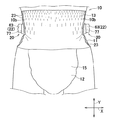
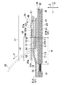
図1〜4を参照すると、本発明の使い捨て着用物品の一例として示す使い捨ておむつ10は、縦方向Y及びそれに交差(直交)する横方向Xとを有し、肌当接面及びそれに対向する非肌当接面と、ウエスト周り方向へ延びる環状の弾性ウエストパネル11と、弾性ウエストパネル11と接合される吸液構造体12と、前ウエスト域(第1又は第2ウエスト域)13と、後ウエスト域(第1又は第2ウエスト域)14と、前後ウエスト域13,14間に位置するクロッチ域15とを含む。おむつ10は、縦方向Yに沿って延びて横方向Xの寸法を二等分する縦軸に関して対称に形成されており、弾性ウエストパネル11は、前ウエスト域13に位置する前ウエストパネル16と、後ウエスト域14に位置する後ウエストパネル17とから構成される。なお、本明細書における「使い捨て着用物品」は、ウエスト開口と一対のレッグ開口とを有する、いわゆるプルオン型(パンツ型)の着用物品であって、例えば、着用者の脚をレッグ開口に挿入してその物品を着用者のウエストに引き上げることにより身体に着用させるものを意味する。   With reference to FIGS. 1 to 4, the disposable diaper 10 shown as an example of the disposable wearing article according to the present invention has a longitudinal direction Y and a transverse direction X intersecting (orthogonal to) it, and a skin contact surface and a non-facing surface Skin contact surface, annular elastic waist panel 11 extending around the waist, liquid absorbing structure 12 joined to elastic waist panel 11, front waist region (first or second waist region) 13, rear It includes a waist area (first or second waist area) 14 and a crotch area 15 located between the front and rear waist areas 13 and 14. The diaper 10 is formed symmetrically with respect to a longitudinal axis extending along the longitudinal direction Y and bisecting the dimension in the lateral direction X, and the elastic waist panel 11 is formed with the front waist panel 16 located in the front waist region 13 , And a rear waist panel 17 located in the rear waist region 14. The “disposable wearing article” in the present specification is a so-called pull-on (pants-type) wearing article having a waist opening and a pair of leg openings, and for example, inserting the leg of the wearer into the leg opening It means what is made to wear on the body by pulling up the article to the waist of the wearer.

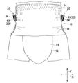
後ウエストパネル17の両側縁部18の外面には、それぞれ、テープタブ20の近位部21が固定されている。テープタブ20は、横方向Xの外側へ伸展可能に折り畳まれており、おむつ10を丸めて廃棄するときに使用する廃棄テープとして使用することができる。また、廃棄テープのほかに、比較的に胴回り寸法の小さい着用者に前後ウエスト域13,14をフィットさせるためのサイズ調整用テープとして使用することもできる。本明細書において、「テープタブ20が伸展可能に折り畳まれている」とは、単数又は複数のテープ基材から形成されたテープタブ20が、二つ折り、三つ折りさらにそれ以上に複数折り畳まれて伸展可能に後ウエスト域14に取り付けられることを意味する。   The proximal portions 21 of the tape tabs 20 are fixed to the outer surfaces of the side edges 18 of the rear waist panel 17, respectively. The tape tab 20 is foldable to the outside in the lateral direction X, and can be used as a waste tape used when the diaper 10 is rolled and discarded. In addition to the waste tape, it can also be used as a size adjustment tape for fitting the front and rear waist areas 13 and 14 to a relatively small waist size wearer. In the present specification, "the tape tab 20 is foldably foldable" means that the tape tab 20 formed of one or more tape substrates can be folded in two, three or more and extended. To be attached to the rear waist region 14.

前後ウエスト域13,14は、それぞれ、横方向Xへ延びる内端縁13a,14aと、縦方向Yにおいて内端縁13a,14aと離間対向して横方向Xへ延びる外端縁13b,14bと、内外端縁13a,13b,14a,14b間において縦方向Yへ延びる両側縁13c,13d,14c,14dとによって画定された横長矩形状を有する。   The front and rear waist regions 13, 14 respectively have an inner end 13a, 14a extending in the lateral direction X, and an outer end 13b, 14b extending in the lateral direction X opposite to the inner end 13a, 14a in the longitudinal direction Y , Between the inner and outer end edges 13a, 13b, 14a, 14b, it has a horizontally long rectangular shape defined by both side edges 13c, 13d, 14c, 14d extending in the longitudinal direction Y.

前ウエスト域13の両側縁13c,13dのそれぞれと後ウエスト域14の両側縁14c,14dとは、互いに重ね合わされて、縦方向Yへ間欠的に位置する側部シーム域23によって連結され、ウエスト開口24及び一対のレッグ開口とが画成される。側部シーム域23は、公知の接合手段、例えば、熱エンボス加工、ソニック加工等の各種の熱溶着手段によってなされる。テープタブ20は、その長さ方向において互いに対向する第1端(自由端)及び第2端(固定端)と、後ウエスト域14の両側縁部18に固定された近位部21と、近位部21と連続的に延びる遠位部22とを有する。   Each of the side edges 13c and 13d of the front waist region 13 and the side edges 14c and 14d of the rear waist region 14 are overlapped with each other and connected by the side seam regions 23 intermittently located in the longitudinal direction Y An opening 24 and a pair of leg openings are defined. The side seam area 23 is made by known bonding means, for example, various heat welding means such as heat embossing, sonic processing and the like. The tape tab 20 has a first end (free end) and a second end (fixed end) opposite to each other in its length direction, a proximal portion 21 fixed to both side edges 18 of the rear waist area 14, and a proximal portion It has a portion 21 and a distal portion 22 extending continuously.

本実施形態において、テープタブ20は、後ウエスト域14の両側縁部18における縦方向Yの中央部近傍に配置されている。テープタブ20がかかる配置態様を有することによって、おむつ10を丸めて廃棄する際、例えば、テープタブ20を掛け回してクロッチ域15の外面に遠位部22を止着して運搬するとき等において、ウエスト開口が開いて排泄物が露出しないようにバランス良く丸めた形態を維持することができる。ただし、本発明の効果を奏する限りにおいて、テープタブ20は、後ウエスト域14の両側縁部18において縦方向Yの中央部以外の部分に配置されていてもよいし、一方の側縁部18にのみ取り付けられていてもよいし、後ウエスト域14の側縁部18ではなく前ウエスト域13の少なくとも一方の側縁部に取り付けられていてもよい。さらに、廃棄するときにウエスト開口及びレッグ開口から排泄物が漏れ出るのを防止できる限りにおいて、前ウエスト域13/後ウエスト域14のウエスト開口の近傍に単数又は複数配置されていてもよい。   In the present embodiment, the tape tab 20 is disposed in the vicinity of the central portion in the longitudinal direction Y at the side edges 18 of the rear waist region 14. By having the tape tab 20 having such an arrangement, when the diaper 10 is rolled and discarded, for example, when the tape tab 20 is looped and the distal portion 22 is fastened to the outer surface of the crotch area 15 and transported, A well-rounded form can be maintained so that the opening is open and the waste is not exposed. However, as long as the effects of the present invention can be achieved, the tape tabs 20 may be disposed at portions other than the central portion in the longitudinal direction Y at the side edges 18 of the rear waist region 14. It may be attached only or may be attached to at least one side edge of the front waist area 13 instead of the side edge 18 of the rear waist area 14. Furthermore, one or more may be disposed in the vicinity of the waist opening of the front waist region 13 / rear waist region 14 as long as waste can be prevented from leaking out from the waist opening and the leg openings when discarding.

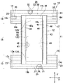
図3を参照すると、前後ウエストパネル16,17は、それぞれ、前後ウエスト域13,14を形成する略横長矩形状の前後ウエストシート25,26を有する。前後ウエストシート25,26は、それぞれ、肌当接面側に位置する内面シート27,29と、非肌当接面側に位置する外面シート28,30とを有する。前ウエストシート25の内外面シート28,29間には、横方向へ延びる複数条のストリング状又はストランド状の前ウエスト弾性体31が伸長状態で収縮可能に取り付けられている。また、後ウエストシート26の内外面シート29,30間には、横方向へ延びる複数条のストリング状又はストランド状の後ウエスト弾性体32が伸長状態で収縮可能に取り付けられている。前後ウエスト域13,14は、それぞれ、前後ウエスト弾性体31,32の収縮力によって横方向Xへ伸縮可能な前後ウエスト弾性域を有する。   Referring to FIG. 3, the front and rear waist panels 16 and 17 have front and rear waist sheets 25 and 26 which have substantially horizontally long rectangular shapes forming front and rear waist regions 13 and 14, respectively. The front and rear waist sheets 25 and 26 respectively have inner sheets 27 and 29 located on the skin contact surface side and outer sheets 28 and 30 located on the non-skin contact surface side. Between the inner and outer sheets 28, 29 of the front waist sheet 25, a plurality of string-like or strand-like front waist elastic bodies 31 extending in the lateral direction are attached retractably in an extended state. Further, between the inner and outer sheets 29 and 30 of the rear waist sheet 26, a plurality of string-like or strand-like rear waist elastic bodies 32 extending in the lateral direction are attached so as to be contractible in an extended state. The front and rear waist regions 13 and 14 have front and rear waist elastic regions that can be expanded and contracted in the lateral direction X by the contraction force of the front and rear waist elastics 31 and 32, respectively.

前後ウエストシート25,26としては、質量が約10〜40g/mであり、繊維密度が約0.03〜0.1g/cmである、例えば、スパンボンド不織布、SMS(スパンボンド・メルトブローン・スパンボンド)不織布、エアスルー不織布、プラスチックシート、またはそれらのラミネートシート等を用いることができる。前後ウエスト弾性体31,32には、例えば、繊度が約300〜500dtex、伸長倍率が1.5〜3.5倍のストリング状又はストランド状の弾性材料を用いることができる。前後ウエスト弾性体31,32は、その太さや伸長倍率は適宜変更することができる。 The front and rear waist sheets 25 and 26 have a weight of about 10 to 40 g / m 2 and a fiber density of about 0.03 to 0.1 g / cm 3 , for example, a spunbond nonwoven fabric, SMS (spunbond meltblown Spunbond) Non-woven fabric, air-through non-woven fabric, plastic sheet, or laminate sheet thereof can be used. For example, a string-like or strand-like elastic material having a fineness of about 300 to 500 dtex and an elongation ratio of 1.5 to 3.5 can be used for the front and rear waist elastics 31 and 32. The thickness and the extension ratio of the front and rear waist elastics 31, 32 can be changed as appropriate.

吸液構造体12は、縦長の矩形状であって、前端部12Aと、後端部12Bと、前後端部12A,12B間に位置する中央部12Cとを有する。吸液構造体12は、肌当接面側に位置し、透液性を有する繊維不織布製の身体側ライナ40と、曲状の両側縁を有する吸液性の吸収体41と、吸収体41の底面全体を覆う不透液性の防漏シート42と、吸液構造体12の非肌当接面全体を形成する疎水性の被覆シート43とを有する。吸収体41は、フラッフパルプと超吸収性ポリマー粒子等との混合物から形成された芯材と、芯材全体を被包するティッシュペーパ等の液吸収拡散性のコアラップシートとを含む。   The liquid-absorbent structure 12 is a vertically long rectangular shape, and has a front end 12A, a rear end 12B, and a central portion 12C located between the front and rear ends 12A and 12B. The liquid-absorbent structure 12 is located on the skin contact surface side, and is a body-side liner 40 made of a liquid-permeable fibrous non-woven fabric, a liquid-absorbent absorbent body 41 having curved side edges, and an absorbent body 41. And a hydrophobic covering sheet 43 that forms the entire non-skin contact surface of the liquid absorbent structure 12. The absorbent body 41 includes a core formed of a mixture of fluff pulp and superabsorbent polymer particles and the like, and a liquid-absorbent and diffusive core wrap sheet such as tissue paper which encapsulates the entire core.

被覆シート43は、防漏シート42の両側縁から横方向Xの外側に位置する両側部44を有する。両側部44は、防漏シート42の両側縁に沿って内側に折曲され、防漏シート42と身体側ライナ40とに固定される。両側部44の外側縁には、身体側ライナ40に固定されていない、スリーブ状の自由縁部43aが位置し、自由縁部43aの内部には縦方向Yへ延びる複数条のストリング状又はストランド状のカフ弾性体45が伸長状態で収縮可能に配設される。カフ弾性体45が収縮することによって、自由縁部43aが身体側ライナ40から着用者の身体側へ離間し、着用者の大腿部にフィットして排泄物の漏れを防止する。また、被覆シート43の両側部44と防漏シート42との間には、複数条のストリング状又はストランド状のレッグ弾性体46が配設される。   The cover sheet 43 has both side portions 44 located outside in the lateral direction X from both side edges of the leakproof sheet 42. Both side portions 44 are bent inward along the side edges of the leakproof sheet 42 and fixed to the leakproof sheet 42 and the body side liner 40. A sleeve-like free edge 43a, not fixed to the body-side liner 40, is located at the outer edge of the two side portions 44, and a plurality of strings or strands extending in the longitudinal direction Y inside the free edge 43a. -Shaped cuff elastic body 45 is disposed so as to be contractible in an extended state. The contraction of the cuff elastic body 45 separates the free edge 43a from the body side liner 40 toward the body of the wearer and fits the thighs of the wearer to prevent leakage of excrement. Further, between the side portions 44 of the cover sheet 43 and the leak-barrier sheet 42, a plurality of string-like or strand-like leg elastic bodies 46 are disposed.

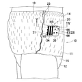
図5は、図4のV−V線に沿う断面図、図6は、前後ウエスト域13,14がその外面に皺が形成されない程度に縦方向Y及び横方向Xに伸長された状態における、図5と同様の断面図である。なお、図4〜6及び以下の説明は、おむつ10の一方側部について示しているが、他方側部においても同様の構成を有する。   5 is a cross-sectional view taken along the line V-V in FIG. 4, and FIG. 6 is a state in which the front and rear waist regions 13 and 14 are extended in the longitudinal direction Y and the lateral direction X to the extent that wrinkles are not formed on the outer surface It is sectional drawing similar to FIG. 4 to 6 and the following description show one side portion of the diaper 10, but the other side portion also has a similar configuration.

図4〜6を参照すると、テープタブ20は、厚さ方向Zを有し、後ウエスト域14の側縁部18の外面に接合部(第1及び第3接合部71,73)を介して固定された近位部21と厚さ方向Zにおいて近位部21と間接的又は直接的に対向する遠位部22とを有する。近位部21は、側部シーム域23に固定された第1近位部21Aと、第1近位部21Aの横方向Xの内側においてそれと離間して位置する第2近位部21Bとを有する。本明細書において、「近位部」とは、テープタブ20のうちの後ウエスト域14の外面に固定された単数又は複数の部分を意味し、それらが同一又は別のテープ基材から形成されたものを意味する。   4 to 6, the tape tab 20 has a thickness direction Z and is fixed to the outer surface of the side edge 18 of the rear waist region 14 via the joints (first and third joints 71 and 73). And a distal portion 22 opposite to the proximal portion 21 indirectly or directly in the thickness direction Z. The proximal portion 21 includes a first proximal portion 21A fixed to the side seam area 23 and a second proximal portion 21B spaced from the first proximal portion 21A in the lateral direction X. Have. As used herein, “proximal” means one or more portions of the tape tab 20 secured to the outer surface of the back waist region 14 and they are formed from the same or another tape substrate I mean one.

テープタブ20は、近位部21と遠位部22との間に位置してそれらと厚さ方向Zにおいて対向する中間部61をさらに有する。本実施形態に係るテープタブ20は、断面Z字型に折り畳まれた複数のテープ基材(テープ片)から形成されており、具体的には、第2近位部21Bを形成する第1テープ基材51と、第1近位部21A,中間部61及び遠位部22を形成する第2テープ基材52とを有する。   The tape tab 20 further has an intermediate portion 61 located between the proximal portion 21 and the distal portion 22 and facing them in the thickness direction Z. The tape tab 20 which concerns on this embodiment is formed from several tape base materials (tape piece) folded in the cross-sectional Z shape, and, specifically, the 1st tape base which forms the 2nd proximal part 21B A material 51 and a second tape base 52 forming a first proximal portion 21A, an intermediate portion 61 and a distal portion 22 are provided.

第1テープ基材51は、一方端部(第1折曲部56a)が第1折曲ライン56に沿って厚さ方向Zの外側へ折り曲げられており、該折曲部56aと第2テープ基材52とが第2接合部72で接合されている。第2テープ基材52は、その長さ方向の略中央部に位置する第2折曲ライン57に沿って2つ折りにされた状態で側縁部18及び第1テープ基材51に固定されている。第1近位部21Aは、第2テープ基材52の一方端部が第3接合部73を介して側縁部18に固定されることによって形成され、中間部61は第1近位部21Aから横方向Xの内側へ向かって延びる部分から形成され、遠位部22は、中間部61の厚さ方向Zの外側において第2折曲ライン57から横方向Xの外側へ向かって延びる部分(第2折曲部57a)から形成される。第2テープ基材52は、外面20aとその反対側に位置する内面52bとを有する。第2テープ基材52の外面20aは、折曲された状態におけるテープタブ20の外面を形成し、第2テープ基材52の内面52aは、遠位部22の内面を形成する。   The first tape base material 51 has one end (first bent portion 56a) bent outward along the first bending line 56 in the thickness direction Z, and the bent portion 56a and the second tape The base member 52 is bonded at the second bonding portion 72. The second tape base material 52 is fixed to the side edge 18 and the first tape base material 51 in a state where it is folded in two along a second bending line 57 located substantially at the center in the length direction There is. The first proximal portion 21A is formed by fixing one end of the second tape base 52 to the side edge 18 via the third joint portion 73, and the middle portion 61 is formed by the first proximal portion 21A. The distal portion 22 extends from the second bending line 57 outward in the lateral direction X from the second bending line 57 at the outer side in the thickness direction Z of the middle portion 61. It is formed from the second bent portion 57a). The second tape substrate 52 has an outer surface 20a and an inner surface 52b opposite to the outer surface 20a. The outer surface 20 a of the second tape substrate 52 forms the outer surface of the tape tab 20 in the bent state, and the inner surface 52 a of the second tape substrate 52 forms the inner surface of the distal portion 22.

近位部21,中間部61及び遠位部22は、互いに積層された状態において、第1及び第2折曲ライン56,57の間に位置し、複数のドット状を有する仮止め部65,66によって仮止めされる。遠位部22は、第1折曲部56aに位置する第1仮止め部65から横方向Xの外側に延びる摘持部63をさらに有する。仮止め部65,66間における遠位部62の内面には、フックシート68aとメカニカルファスナのフック要素68bから形成された止着域68が配置される。止着域68は、おむつ10の外面がプラスチックフィルムから形成されている場合には、感圧性の粘着剤等であってもよい。   The proximal portion 21, the intermediate portion 61 and the distal portion 22 are located between the first and second bending lines 56, 57 in a state of being stacked on one another, and have a plurality of dot-shaped temporary fixing portions 65, Temporarily fixed by 66. The distal portion 22 further includes a grip portion 63 extending outward in the lateral direction X from the first temporary fixing portion 65 located at the first bending portion 56a. Located on the inner surface of the distal portion 62 between the tacking portions 65, 66 is a fastening zone 68 formed from the hook sheet 68a and the hook element 68b of the mechanical fastener. The fastening area 68 may be a pressure sensitive adhesive or the like when the outer surface of the diaper 10 is formed of a plastic film.

テープタブ20を形成するテープ基材は、繊維不織布、少なくともその一部に、例えば、ポリエチレン、ポリプロピレン、ポリスチレン等の熱融着性の合成繊維を含むものであって、例えば、質量が約30〜100g/m、好ましくは質量が約40g/m以上のスパンボンド繊維不織布を用いることができる。 The tape base material for forming the tape tab 20 is a non-woven fiber fabric, including at least a part of a heat-sealable synthetic fiber such as polyethylene, polypropylene, polystyrene, etc., for example, having a weight of about 30 to 100 g / m 2, preferably the mass can be used about 40 g / m 2 or more spunbond nonwoven.

第1〜第3接合部71,72,73には、接着又はソニックシールやヒートシール等の溶着による各種公知の接合手段を用いることがき、例えば、接着手段を用いる場合には、質量約5〜20g/mのホットメルト接着剤を使用することができる。仮止め部65,66は、公知の加圧処理や加圧加熱処理を施すことによって形成することができ、例えば、エンボス処理またはソニック処理によって形成することができる。加圧加熱処理をする場合、テープタブ20自体が熱可塑性の合成繊維を有する場合には、熱融着によってより安定的に仮止めすることができる。また、図4を参照すると、仮止め部65,66は、縦方向Y及び横方向Xにおいて互いに離間するように配置された複数のドット状を有する。このように、仮止め部65,66が積層された状態におけるテープタブ20の外面に局所的に配置されることによって、それが外面全体に配置される場合に比して、テープタブ20の柔軟性が損なわれるおそれはない。 For the first to third bonding portions 71, 72, 73, various known bonding means such as adhesion or welding such as sonic seal or heat seal can be used. A 20 g / m 2 hot melt adhesive can be used. The temporary fixing portions 65 and 66 can be formed by performing known pressure treatment and pressure heat treatment, and can be formed by, for example, embossing or sonic treatment. In the case of heat treatment under pressure, if the tape tab 20 itself has thermoplastic synthetic fibers, it can be temporarily fixed more stably by heat fusion. Further, referring to FIG. 4, the temporary fixing portions 65 and 66 have a plurality of dot shapes arranged to be separated from each other in the longitudinal direction Y and the lateral direction X. In this manner, by locally arranging the temporary fixing portions 65 and 66 on the outer surface of the tape tab 20 in the stacked state, the flexibility of the tape tab 20 is improved as compared with the case where it is arranged on the entire outer surface. There is no risk of damage.

図4及び後述する図7(a),(b)を参照すると、第2テープ基材52の外面20aを形成する一方面には、印刷された複数の第1表示要素34aを有する第1表示域34と、印刷された複数の第2表示要素35aを有する第2表示域35とが位置する。第1表示域34は摘持部63の外面20aに位置し、第2表示域35は遠位部22のうちの摘持部63を除く残余部分64の外面20aに位置している。第1表示要素34aと第2表示要素35aとは、視覚上区別できる程度に、互いに異なる表示を有する。本実施形態においては、第1表示要素34aは、テープタブ20の幅方向へ延びる複数条のラインから構成されており、第2表示要素35aは、複数のドットから構成されており、第1表示域34は縞模様、第2表示域35は水玉模様をそれぞれ有する。   Referring to FIG. 4 and FIGS. 7A and 7B described later, a first display having a plurality of printed first display elements 34 a on one surface forming the outer surface 20 a of the second tape base material 52 An area 34 and a second display area 35 having a plurality of printed second display elements 35a are located. The first display area 34 is located on the outer surface 20 a of the grip 63, and the second display area 35 is located on the outer surface 20 a of the remaining portion 64 of the distal portion 22 excluding the grip 63. The first display element 34a and the second display element 35a have different displays to the extent that they can be distinguished visually. In the present embodiment, the first display element 34a is composed of a plurality of lines extending in the width direction of the tape tab 20, and the second display element 35a is composed of a plurality of dots. 34 has a stripe pattern, and the second display area 35 has a polka dot pattern.

第1及び第2表示要素34a,35aは、互いに視覚上区別しうる限りにおいて、白色及び乳白色以外の色彩、文字、デザイン、記号等の各種公知の表示を用いることができる。また、本明細書において「第1表示要素34aと第2表示要素35aとが、互いに異なる表示を有する」とは、視覚上区別できる程度に互いの表示が異なることを意味し、例えば、それらの表示が異なる図柄であったり、同大同形の図柄であって着色された色彩が異なるものであったり、一方が絵柄であるのに対し、他方が文字から構成されている場合等を含むものである。   As the first and second display elements 34a and 35a, various known displays such as colors other than white and milky white, characters, designs, symbols, etc. can be used as long as they can be visually distinguished from each other. Further, in the present specification, "the first display element 34a and the second display element 35a have different displays" means that the displays of the first display element 34a and the second display element 35a are different from each other to the extent that they can be visually distinguished. This includes the case where the display is a different pattern, is the same shape and shape, and is different in colored color, or one is a pattern while the other is a character.

図6を参照すると、摘持部63を容易に摘持するために、摘持部63の大きさは比較的に大きいことが好ましく、具体的には、横方向Xの寸法L2が約10mm以上、遠位部22の横方向Xの寸法L1の約20%以上であることが好ましい。このように、摘持部63の長さ寸法が比較的に大きいことによって、横方向Xの外方へ延びる摘持部63を摘持し易くなるとともに、おむつ10に背面視において装飾要素82を容易に視認することができる。また、側部シーム域23と仮止め部65との横方向Xにおける離間寸法Rは、約5mm以上であることが好ましい。このように、離間寸法Rが比較的に大きく形成されることによって、摘持部63の基端近傍が離間部分77によって横方向Xの外側へ向かって起立されて、摘持部63が正面視及び背面視において横方向Xの外側へ突出するような態様となる。   Referring to FIG. 6, in order to easily hold the holding portion 63, the size of the holding portion 63 is preferably relatively large. Specifically, the dimension L2 in the lateral direction X is about 10 mm or more Preferably, it is about 20% or more of the dimension L1 in the lateral direction X of the distal portion 22. Thus, the relatively large length dimension of the grip portion 63 makes it easy to grip the grip portion 63 extending outward in the lateral direction X, and the diaper 10 has the decorative element 82 in a rear view. It can be easily viewed. Further, the separation dimension R in the lateral direction X between the side seam area 23 and the temporary fixing portion 65 is preferably about 5 mm or more. Thus, by forming the separation dimension R relatively large, the vicinity of the base end of the grip portion 63 is erected toward the outside in the lateral direction X by the separation portion 77, and the grip portion 63 is viewed from the front. And it becomes an aspect which protrudes outside the cross direction X in back view.

このように折り畳まれた状態で後ウエスト域14の側縁部18に取り付けられたテープタブ20は、操作者が摘持部63を摘持してそれを引っ張り方向Pへ引っ張ることによって、仮止め部65,66による仮止めが解除される。本実施形態に係るテープタブ20は、後ウエスト域14に固定された近位部21が横方向Xにおいて互いに離間する第1近位部21Aと第2近位部21Bとからなる、いわゆるY形のテープタブであるから、引っ張り方向Pへ引っ張ったときに、第1近位部21Aに作用する剥離力を低減することができる。また、かかるテープタブ20が接合態様を有することによって、引っ張り方向Pではなく横方向Xの内側へ向かって摘持部63を引っ張って展開するときにも、第1近位部21Aに作用する剥離力を低減することができる。また、テープタブ20が所要の剥離強度を有する限りにおいて、1つのテープ基材のみから形成されていてもよいし、2つ以上の複数のテープ基材から形成されていてもよい。 The tape tab 20 attached to the side edge 18 of the rear waist region 14 in the folded state in this manner allows the operator to hold the holding portion 63 and pull it in the pulling direction P to thereby temporarily fix the holding portion 63. The temporary fixing by 65, 66 is released. The tape tab 20 according to the present embodiment is a so-called Y-shape including a first proximal portion 21A and a second proximal portion 21B in which the proximal portions 21 fixed to the rear waist region 14 are mutually separated in the lateral direction X. Since it is a tape tab, when pulled in the pulling direction P, the peeling force acting on the first proximal portion 21A can be reduced. In addition, when the tape tab 20 has a bonding mode, the peeling force acting on the first proximal portion 21A also when the grip portion 63 is pulled and expanded inward in the lateral direction X instead of in the pulling direction P. Can be reduced. Moreover, as long as the tape tab 20 has a required peel strength, it may be formed only from one tape substrate, or may be formed from two or more tape substrates.

図5を参照すると、おむつ10の着用状態及び非着用状態において、後ウエスト域14全体は後ウエスト弾性体32によって横方向Xに収縮されて複数のギャザー80が形成される。後ウエスト域14における、テープタブ20の近位部21の配置領域には、少なくとも1条の後ウエスト弾性体32が位置しており、該弾性体32の収縮力によって、近位部21はウエスト周り方向へ連続する起伏形状を有する。本実施形態においては、テープタブ20がおむつ10の外面に取り付けられていない状態において、前後ウエスト弾性域の収縮力はほぼ同等となるように、前後ウエスト弾性体31,32の本数、繊度、ピッチ等が適宜設定されている。   Referring to FIG. 5, in the wearing state and the non-wearing state of the diaper 10, the entire rear waist region 14 is contracted in the lateral direction X by the rear waist elastic body 32 to form a plurality of gathers 80. At least one rear waist elastic body 32 is located in the rear waist region 14 in the placement area of the proximal portion 21 of the tape tab 20, and the contraction force of the elastic body 32 causes the proximal portion 21 to wrap around the waist. It has an undulating shape that is continuous in the direction. In the present embodiment, in a state where the tape tab 20 is not attached to the outer surface of the diaper 10, the number of the front and rear waist elastics 31, 32 such as the size, the pitch, etc. are substantially equal. Is set appropriately.

通常、前後ウエスト弾性域において互いの収縮力がほぼ同等である場合には、図5において仮想線で示すように、側部シーム域23は前側又は後側へ傾くことなく横方向Xの外方へ突出するように延びる。しかし、本実施形態においては、後ウエスト域14の側縁部18にテープタブ20の近位部21が位置することによって、後ウエスト弾性域における近位部21の存在する弾性域の収縮力が低減されて、前後方向において対向する前ウエスト域13の弾性域よりもその収縮力が低くなる。そのため、側部シーム域23においては、内側に位置する前ウエスト域13の側縁部からなる前方部分23aの収縮量が外側に位置する後ウエスト域14の側縁部18からなる後方部分23bの収縮量よりも大きくなり、前方部分23aの横方向Xの寸法が後方部分23bのそれよりも小さくなって、側部シーム域23は後方部分23bを外側として横方向Xの内側へ湾曲した形状となる。   Generally, in the case where the contraction forces are substantially equal in the front and rear waist elastic regions, as shown by phantom lines in FIG. Extend to project into. However, in the present embodiment, by locating the proximal portion 21 of the tape tab 20 at the side edge 18 of the rear waist region 14, the contraction force of the elastic region where the proximal portion 21 is present in the rear waist elastic region is reduced. As a result, the contraction force becomes lower than the elastic area of the front waist area 13 opposed in the front-rear direction. Therefore, in the side seam area 23, the amount of contraction of the front portion 23a consisting of the side edge of the front waist area 13 located inside is the amount of contraction of the rear part 23b consisting of the side edge 18 of the rear waist area 14 located outside With the amount of contraction being greater and the dimension in the lateral direction X of the front portion 23a being smaller than that of the rear portion 23b, the side seam area 23 is curved inward in the lateral direction X with the rear portion 23b as the outer side. Become.

このように、側部シーム域23が湾曲した形状を有することによって、側部シーム域23及びそれの横方向Xの外側及び内側に隣接する部分も同様に湾曲した形状となるとともに、側部シーム域23とその横方向Xの外側に隣接する部分81とに固定された第1近位部21Aも湾曲した形状となる。仮止め部65よりも側部シーム域23側に位置する摘持部63は、それと対向する中間部61と接合されていないので、中間部61と離間して厚さ方向Zの外側へ延びる。   Thus, by having the side seam area 23 having a curved shape, the side seam area 23 and the portion adjacent to the outer side and the inner side in the lateral direction X of the side seam area 23 have a curved shape as well. The first proximal portion 21A fixed to the area 23 and the portion 81 adjacent to the outside in the lateral direction X also has a curved shape. The pinching portion 63 positioned closer to the side seam area 23 than the temporary tacking portion 65 is separated from the middle portion 61 and extends outward in the thickness direction Z since it is not joined to the middle portion 61 opposed thereto.

図1及び2を参照すると、前後ウエスト域13,14が収縮された状態、すなわち、おむつ10の着用状態において、テープタブ20がかかる態様を有することから、摘持部63がおむつ10の両側縁部10bから横方向Xの外側へ突出した状態となる。そのため、おむつ10の廃棄時やサイズ調整時においてテープタブ20を展開するときに、摘持部63が湾曲した中間部61と重なって摘持し難くなるおそれはなく、中間部61から離間して厚さ方向Zへ延出した摘持部63を容易に摘持することができるので、操作性に優れる。   With reference to FIGS. 1 and 2, since the tape tab 20 has such an aspect in which the front and rear waist areas 13 and 14 are contracted, that is, the wearing state of the diaper 10, the grip portion 63 has both side edges of the diaper 10. It will be in the state protruded to the outside of cross direction X from 10b. Therefore, when developing the tape tab 20 at the time of discarding or size adjustment of the diaper 10, there is no possibility that the gripping portion 63 overlaps with the curved intermediate portion 61 and it becomes difficult to grip and separate from the intermediate portion 61 As it is possible to easily hold the holding portion 63 extended in the longitudinal direction Z, the operability is excellent.

再び、図5を参照すると、後ウエスト域14が複数のギャザー80による起伏形状を有し、それに固定された第2近位部21Bも横方向Xへ収縮して起伏形状を有する一方、第2近位部21Bと対向する中間部61及び遠位部22とは、第2近位部21Bに固定されておらず、かつ、遠位部22の内面には止着域68が形成されて局所的に剛性が高くなっていることから起伏していない。第1近位部21Aと第2近位部21Bとが横方向Xにおいて互いに離間する離間部分77は、それと対向する側縁部18が収縮することから厚さ方向Zの外側へ凸曲した形状を有する。仮止め部65が第1折曲部56aに位置していることから、離間部分77は摘持部63の基端近傍と対向しており、そのために摘持部63の基端近傍が離間部分77上に位置して摘持部63はより安定的に横方向Xの外側へ延出した態様を呈する。また、摘持部63が凸曲した離間部分77上に位置するので、引っ張り方向Pへスライドさせるように摘持部63を引っ張ることによって仮止め部66,65の仮止めを解除することができる。このように、主としてせん断力で仮止めを解除することができるので、より小さい引っ張り力でテープタブ20を展開することができる。   Again referring to FIG. 5, while the rear waist region 14 has an undulating shape due to the plurality of gathers 80, the second proximal portion 21B fixed thereto also shrinks in the transverse direction X to have an undulating shape, The proximal portion 21B and the opposing middle portion 61 and the distal portion 22 are not fixed to the second proximal portion 21B, and a fastening region 68 is formed on the inner surface of the distal portion 22 so as to be localized. It is not undulating because the rigidity is high. A separated portion 77 in which the first proximal portion 21A and the second proximal portion 21B are mutually separated in the lateral direction X has a shape convex outward in the thickness direction Z because the opposing side edge 18 contracts. Have. Since the temporary fixing portion 65 is located at the first bending portion 56a, the separated portion 77 faces the vicinity of the proximal end of the gripping portion 63, and therefore the proximal end vicinity of the gripping portion 63 is a separated portion Positioned on 77, the grip 63 has a more stably extending outward in the lateral direction X. In addition, since the gripping portion 63 is located on the convexly curved separated portion 77, the temporary tacking of the temporary tacking portions 66 and 65 can be released by pulling the gripping portion 63 so as to slide in the pulling direction P. . In this manner, since the temporary tacking can be released mainly by the shearing force, the tape tab 20 can be deployed with a smaller pulling force.

図7(a)は、折り畳まれた状態におけるテープタブ20の平面図、図7(b)は、展開された状態におけるテープタブ20の平面図、図8(a)は、おむつ10を廃棄するときに、テープタブ20を操作する様子を示す図、図8(b)は、折り畳んだおむつ10にテープタブ20を止着した様子を示す図である。なお、図8(a),(b)に示すおむつ10は、両側部を前ウエスト域13又は後ウエスト域14が内側になるように横方向Xの内側へ折り曲げた後に、横方向Xへ延びる折曲線に沿ってクロッチ域15をウエスト域側へ折り曲げることによってコンパクトになった形態であって、おむつ10を廃棄するときに採用される折曲態様として公知のものである。   7 (a) is a plan view of the tape tab 20 in the folded state, FIG. 7 (b) is a plan view of the tape tab 20 in the expanded state, and FIG. FIG. 8B is a view showing how the tape tab 20 is fixed to the folded diaper 10. The diaper 10 shown in FIGS. 8A and 8B extends in the lateral direction X after being bent inward in the lateral direction X so that the front waist region 13 or the rear waist region 14 is on the inner side. It is a form made compact by bending the crotch area 15 to the waist area side along a folding line, and is known as a folding mode adopted when the diaper 10 is discarded.

図7(a),(b)を参照すると、既述のとおり、摘持部63の外面には、テープタブ20の幅方向へ延びる複数のライン状の第1表示要素34aから構成された縞模様を有する第1表示域34が位置し、遠位部22のうちの摘持部63を除く残余部分64の外面には、複数のドット状の第2表示要素35aから構成された水玉模様を有する第2表示域35が位置している。通常、テープタブ20は、おむつ10の外面と同様に、不織布製又はプラスチック製のテープ基材本来の白色を有し、おむつ10の外観視においてその外形輪郭を視認し難く、テープタブ20を使用する際に、摘持部63を摘持し難いことがあった。本実施形態に係るおむつ10においては、テープタブ20の外面20aに着色及び/又はデザインが付された第1及び第2表示域34,35が配されていることによって、テープタブ20の外形輪郭を容易に視認することができ、摘持部63を摘持することができる。   Referring to FIGS. 7A and 7B, as described above, the outer surface of the gripping portion 63 is a stripe pattern formed of a plurality of line-shaped first display elements 34a extending in the width direction of the tape tab 20. A first display area 34 having a polka dot pattern formed of a plurality of dot-like second display elements 35 a on the outer surface of the remaining portion 64 of the distal portion 22 excluding the holding portion 63. The second display area 35 is located. In general, the tape tab 20 has an intrinsic white color of a non-woven or plastic tape base like the outer surface of the diaper 10, and when the tape tab 20 is used it is difficult to visually recognize the outer contour of the diaper 10 in appearance. In some cases, it is difficult to hold the holding portion 63. In the diaper 10 according to the present embodiment, the outer contour of the tape tab 20 is facilitated by arranging the first and second display areas 34, 35 in which the outer surface 20a of the tape tab 20 is colored and / or designed. And the holding portion 63 can be held.

テープタブ20の遠位部22において、摘持部63の外面に配された第1表示域34と、残余部分64の外面に位置する第2表示域35とが異なる表示要素を有することから、着用者は、テープタブ20全体に対する摘持部63の相対的な大きさ、範囲を容易に認識することができる。また、このように、テープタブ20を展開するときに摘持するための摘持部63の外面に配置された第1表示域34の表示要素と、残余部分64の外面に配された第2表示域35の表示要素とが相違することから、第1及び第2表示域34,35は、それぞれ、それが配された部分の有する機能を表した機能表示部としての役割を果たしうる。   In the distal portion 22 of the tape tab 20, the first display area 34 disposed on the outer surface of the gripping portion 63 and the second display area 35 located on the outer surface of the remaining portion 64 have different display elements. A person can easily recognize the relative size and range of the gripping portion 63 with respect to the entire tape tab 20. In addition, as described above, the display elements of the first display area 34 disposed on the outer surface of the gripping portion 63 for gripping when the tape tab 20 is deployed, and the second display disposed on the outer surface of the remaining portion 64 Since the display elements of the area 35 are different, the first and second display areas 34 and 35 can each function as a function display unit representing the function of the portion in which it is arranged.

図8(a),(b)を参照すると、おむつ10を廃棄する際には、着用補助者がおむつ10を折り畳んだ後に、一方の手で折り畳まれたおむつ10を押さえるとともに、テープタブ20の摘持部63を摘持し、互いに重ねられた前後ウエスト域13,14からなる第1部分84をクロッチ域15からなる第2部分85に押し当てるように引っ張り方向Pへ引っ張りながら展開する。次に、展開したテープタブ20の止着域68をおむつ10の外面(クロッチ域15の外面)に押し当てて止着する際に、第2表示域35が配された部分を親指で押し当てることによって止着域68が止着される。止着域68は、遠位部22の内面52bに配置されていることからテープタブ20の外観視においてその存在域を視認することが困難であるが、該存在領域に第2表示域35が位置することによって止着域68を確実に指で押し当てて止着させることができる。   Referring to FIGS. 8 (a) and 8 (b), when discarding the diaper 10, after the wearing assistant folds the diaper 10, the user holds the folded diaper 10 with one hand and removes the tape tab 20. The holding portion 63 is held and developed while being pulled in the pulling direction P so as to press the first portion 84 composed of the front and rear waist regions 13 and 14 superimposed on each other against the second portion 85 composed of the crotch region 15. Next, when the fastening area 68 of the expanded tape tab 20 is pressed against the outer surface of the diaper 10 (the outer surface of the crotch area 15) and fastened, the area where the second display area 35 is disposed is pressed with the thumb. The fastening zone 68 is fastened by means of. Since the fastening zone 68 is disposed on the inner surface 52b of the distal portion 22, it is difficult to visually recognize the presence zone in the appearance of the tape tab 20, but the second display zone 35 is located in the presence zone By doing this, the fastening area 68 can be pressed firmly with a finger and fastened.

このように、テープタブ20の外観視において遠位部22の内面に位置する止着域68の存在域を認識するために、第2表示域35は少なくとも止着域68の存在域に配されていればよく、遠位部22のうちの止着域68から横方向Xの内側に位置する部分には第2表示域35が配されていなくてもよい。ただし、遠位部22のうちの摘持部63を除く残余部分64全体の外面に第2表示域35が配されていることによって、着用補助者は意識的に親指の中腹全体で第2表示域35をおむつ10の外面に押し当てることになるので、止着域68及びそれに隣接する部分が押し当てられてより確実に止着がなされ得る。   Thus, the second display area 35 is disposed at least in the presence area of the fixation area 68 in order to recognize the existence area of the fixation area 68 located on the inner surface of the distal portion 22 in the appearance of the tape tab 20 The second display area 35 may not be disposed in a portion of the distal portion 22 located inward in the lateral direction X from the fastening area 68. However, the second display area 35 is disposed on the outer surface of the entire remaining portion 64 excluding the holding portion 63 of the distal portion 22 so that the wearing assistant consciously displays the second display over the entire middle of the thumb. Since the area 35 is pressed against the outer surface of the diaper 10, the fastening zone 68 and the adjacent part thereof can be pressed to secure fastening more reliably.

また、おむつ10は、前後ウエスト域13,14を構成するパネル部材が同大同形であるので、外観において瞬時におむつ10の前後を判別することは困難であるところ、このように、テープタブ20の外面に第1及び第2表示域34,35を配置することによって、第1表示域34が前側、第2表示域35が後側に位置するので、着用者/着用補助者はおむつ10の前後を判別することができる。したがって、前後ウエスト域13,14に前後を区別するための表示がなくても、着用する前に前後の判別を容易にしてスムーズに着用操作を行うことができる。   Further, in the diaper 10, since the panel members constituting the front and rear waist regions 13 and 14 have the same size and shape, it is difficult to distinguish the front and back of the diaper 10 instantaneously in appearance. By arranging the first and second display areas 34 and 35 on the outer surface, the first display area 34 is located on the front side, and the second display area 35 is located on the rear side. Can be determined. Therefore, even if there is no display for distinguishing front and rear in the front and rear waist regions 13 and 14, before and after wearing can be easily distinguished before and after wearing, and wear operation can be performed smoothly.

既述のとおり、本実施形態に係るテープタブ20は、第1近位部21Aが側部シーム域23に固定されていることによって、摘持部63は厚さ方向Zにおいてそれと対向する中間部61と離間して横方向Xの外側へ延びる。さらに、離間部分77が厚さ方向Zの外側へ凸曲した形状をなし、離間部分77上に位置する摘持部63が横方向Xの外側へより延出した態様となる。したがって、遠位部22において摘持部63のみが横方向Xの外側へ突出した態様となり、より摘持が容易となるとともに、第1表示域34を視認しやすくなる。なお、近位部21/第1近位部21Aは、その配置領域が前側へ移動する限りにおいて、側部シーム域23上に位置していなくてもよく、後ウエスト域14の側縁部18であって側部シーム域23よりも横方向Xの内側に位置していてもよい。   As described above, in the tape tab 20 according to the present embodiment, the first proximal portion 21A is fixed to the side seam area 23, so that the grip portion 63 is the middle portion 61 opposite thereto in the thickness direction Z. And extend outward in the lateral direction X. Furthermore, the separated portion 77 has a shape that is convexly curved outward in the thickness direction Z, and the gripping portion 63 located on the separated portion 77 is further extended outward in the lateral direction X. Therefore, in the distal portion 22, only the gripping portion 63 protrudes outward in the lateral direction X, which makes gripping easier and makes the first display area 34 easier to view. Note that the proximal portion 21 / first proximal portion 21A may not be located on the side seam area 23 as long as the placement area moves forward, and the side edge 18 of the rear waist area 14 And may be located inside the lateral direction X more than the side seam area 23.

図7(a)を参照すると、第1表示域34と第2表示域35との境界近傍には、第1仮止め部65が位置している。第1仮止め部65がかかる配置態様を有することによって、中間部61から離間した部分がすべて摘持部63となるから、その全体を容易に摘持することができ、また、第1仮止め部65の横方向Xの内側に止着域68が隣接することによって、止着操作をするときに止着域68を確実におむつ本体10Aの外面に押し当てることができる。   Referring to FIG. 7A, in the vicinity of the boundary between the first display area 34 and the second display area 35, a first temporary fixing portion 65 is located. By having such an arrangement mode of the first temporary fixing portion 65, all parts separated from the intermediate portion 61 become the holding portion 63, so that the whole can be easily held, and the first temporary fixing The fastening area 68 adjacent to the inside of the lateral direction X of the portion 65 ensures that the fastening area 68 can be pressed against the outer surface of the diaper body 10A when performing the fastening operation.

また、テープタブ20の折り畳まれた状態において第1表示域34の第1表示要素34aの総面積が第2表示域35の第2表示要素35aの総面積よりも大きくなっている。一方、テープタブ20の展開された状態においては、第1表示域34の第1表示要素34aの総面積が第2表示域35の第2表示要素35aの総面積よりも小さくなっている。このように、テープタブ20の折り畳まれた状態と展開された状態とで、第1表示要素34aの総面積と第2表示要素35aの総面積との相関関係が異なることから、テープタブ20を使用する際には、摘持部63をより認識し易く、テープタブ20を展開しておむつ10の外面に止着したときには、第2表示要素35aがより認識しやすくなる。したがって、例えば、
第2表示要素35bの装飾性(デザイン性)を第1表示要素34aのそれよりも高くすることによって、テープタブ20の止着状態においては第2表示域35が比較的大きく表れるので、おむつ10の外観視における意匠性が向上する。
In addition, in the folded state of the tape tab 20, the total area of the first display elements 34a of the first display area 34 is larger than the total area of the second display elements 35a of the second display area 35. On the other hand, in the developed state of the tape tab 20, the total area of the first display elements 34a of the first display area 34 is smaller than the total area of the second display elements 35a of the second display area 35. Thus, the tape tab 20 is used because the correlation between the total area of the first display element 34a and the total area of the second display element 35a differs between the folded state and the expanded state of the tape tab 20. In this case, when the tape tab 20 is developed and attached to the outer surface of the diaper 10, the second display element 35a is more easily recognized. Thus, for example,
By making the decorativeness (designability) of the second display element 35 b higher than that of the first display element 34 a, the second display area 35 appears relatively large in the fastened state of the tape tab 20, so The designability in appearance is improved.

第1及び第2表示要素34a,35aには、互いに視覚上区別しうる限りにおいて、着色、文字、デザイン、記号等の各種公知の表示要素を用いることができる。テープタブ20を展開した状態におけるおむつ10の外観上の意匠性を向上させるために、例えば、第2表示要素35aとして複数のドット状からなる水玉模様や複数の三角形、星形、矩形等の非連続性の図柄を用いた場合には、第1表示域34の第1表示要素34aはライン模様等の連続性の図柄であることが好ましい。かかる場合には、第1表示域34と第2表示域35との区別がし易く、両表示域34,35の境界を把握することができる。   As the first and second display elements 34a and 35a, various known display elements such as coloring, characters, designs, symbols and the like can be used as long as they can be visually distinguished from each other. In order to improve the design on the appearance of the diaper 10 in the state in which the tape tab 20 is expanded, for example, a plurality of dot-shaped polka dots as the second display element 35a, discontinuous triangles, stars, rectangles, etc. In the case of using a graphic of character, it is preferable that the first display element 34a of the first display area 34 be a graphic of continuity such as a line pattern. In such a case, the first display area 34 and the second display area 35 can be easily distinguished, and the boundaries between the two display areas 34 and 35 can be grasped.

図7(b)を参照すると、遠位部22は、摘持部63を除く残余部分64を有し、残余部分64の外面20a全体に第2表示域35が位置している。前記テープタブ20を展開した状態において、第2表示域35は、内面52bに止着域68が位置する第1区域64Aと、第1区域64Aと隣接する第2区域64Bと、近位部21側に位置し、かつ、第2テープ基材52とは別体の第1テープ基材51(折曲部分56a)が外面20aに配置された第3区域64Cとを有する。   Referring to FIG. 7 (b), the distal portion 22 has a remaining portion 64 excluding the holding portion 63, and the second display area 35 is located on the entire outer surface 20 a of the remaining portion 64. In the state where the tape tab 20 is developed, the second display area 35 has a first area 64A where the fastening area 68 is located on the inner surface 52b, a second area 64B adjacent to the first area 64A, and the proximal part 21 side. And a third section 64C in which the first tape base 51 (bent portion 56a) separate from the second tape base 52 is disposed on the outer surface 20a.

第1区域64Aでは、内面52bに配置された白色又は乳白色のフックシート68aが透過されることによって、第2テープ基材52の一方面である外面20aに印刷された第2表示要素35aが、第2区域64Bに比べて、より鮮明に視認される。一方、第3区域64Cでは、第1テープ基材51が第2テープ基材52を覆うように配置されているので、第2区域64Bに比べて、第2表示要素35aの視認性が低下する。このように、第2表示域35の各区域64A,64B,64Cにおける第2表示要素35aの視認性の相関関係が、第1区域64A>第2区域64B>第3区域64Cとなるので、第2表示域35は近位部21側から摘持部63側へ向かって色彩が濃くなっている。したがって、第2表示要素35a自体の色彩をコントロールしなくても、各区域64A〜64Cの色の濃淡を相違させることができる。第2表示域35における色の濃淡の相違によるコントラストによって、テープタブ20は意匠性が向上するとともに、着用補助者は第2表示域35全体における止着域68が配置された領域を容易に把握することができる。   In the first area 64A, the second display element 35a printed on the outer surface 20a, which is one surface of the second tape substrate 52, is transmitted by transmitting the white or milky hook sheet 68a disposed on the inner surface 52b. Compared to the second area 64B, it is more clearly visible. On the other hand, in the third area 64C, since the first tape base 51 is disposed so as to cover the second tape base 52, the visibility of the second display element 35a is reduced compared to the second area 64B. . Thus, the correlation of the visibility of the second display element 35a in each of the areas 64A, 64B, 64C of the second display area 35 is such that the first area 64A> the second area 64B> the third area 64C. The color of the second display area 35 is increased from the proximal portion 21 side toward the grip portion 63 side. Therefore, the shades of color of the areas 64A to 64C can be made different without controlling the color of the second display element 35a itself. While the tape tab 20 is improved in design by the contrast due to the difference in color density in the second display area 35, the wearing assistant easily grasps the area where the fastening area 68 in the entire second display area 35 is disposed. be able to.

本実施形態において、摘持部63の外面20aに第1表示域34が配置されているが、外部から視認可能な限りにおいて、摘持部63の内面に第1表示域34が配置されていてもよい。後ウエスト域14の収縮状態において、離間部分77が厚さ方向Zの外側へ凸曲した形状をなし、離間部分77上に位置する摘持部63が横方向Xの外側へより延出した態様となるので、摘持部63の内面が露出する。したがって、摘持部63の内面に第1表示域34が配置されることによっても、着用者は摘持部63を把握することができ、その限りにおいて、外面20aに位置する第1表示域34が内面側から視認できるように透視されていてもよい。さらに、摘持部63の外面20aと内面52bとにおいて、それぞれ、異なる意匠を有する装飾要素を配置してもよい。   In the present embodiment, the first display area 34 is disposed on the outer surface 20 a of the knob 63, but the first display area 34 is disposed on the inner surface of the knob 63 as long as it is visible from the outside. It is also good. In the contracted state of the rear waist region 14, the separated portion 77 has a shape that is convexly curved outward in the thickness direction Z, and the grip portion 63 located on the separated portion 77 extends outward in the lateral direction X As a result, the inner surface of the grip portion 63 is exposed. Therefore, also by disposing the first display area 34 on the inner surface of the grip section 63, the wearer can grasp the grip section 63, and in that respect, the first display area 34 located on the outer surface 20a. May be seen through so as to be visible from the inner side. Furthermore, on the outer surface 20a and the inner surface 52b of the grip portion 63, decorative elements having different designs may be arranged.

図9は、実施例の一例における図6と同様の断面図である。本実施例に係るテープタブ20は、1つのテープ基材が2つに折り畳まれた状態であって、後ウエスト域14の側縁部18に固定された近位部21と、厚さ方向Zにおいて近位部21に対向する遠位部22とを有する。近位部21と遠位部22とは、仮止め部65,66を介して互いに仮止めされており、摘持部63を引っ張って仮止めを解除することによって、テープタブ20を展開しうる。テープタブ20の摘持部63の外面20aには第1表示要素34a(図示せず)を有する第1表示域34が位置し、遠位部22のうちの摘持部63を除く部分64には、第1表示要素34aとは形態の異なる第2表示要素35a(図示せず)を有する第2表示域35が位置している。このように、テープタブ20が、単数のテープ基材を2つに折り畳んだ態様であっても、おむつ10の外観視において第1表示域34と第2表示域35とを区別することができる。   FIG. 9 is a cross-sectional view similar to FIG. 6 in an example of the embodiment. The tape tab 20 according to the present embodiment is in a state in which one tape substrate is folded in two and the proximal portion 21 fixed to the side edge 18 of the rear waist region 14 in the thickness direction Z And a distal portion 22 opposed to the proximal portion 21. The proximal portion 21 and the distal portion 22 are temporarily fixed to each other via the temporary fixing portions 65 and 66, and the tape tab 20 can be deployed by pulling the holding portion 63 to release the temporary fixing. A first display area 34 having a first display element 34a (not shown) is located on the outer surface 20a of the gripping portion 63 of the tape tab 20, and a portion 64 of the distal portion 22 excluding the gripping portion 63 , And a second display area 35 having a second display element 35a (not shown) different in form from the first display element 34a. Thus, even if the tape tab 20 is a mode in which a single tape substrate is folded in two, the first display area 34 and the second display area 35 can be distinguished in the appearance of the diaper 10.

本明細書において、「第1及び第2表示域34,35が視認される」とは、蛍光灯によって一定の明るさを有する室内、例えば、白昼色(色温度が約4600〜5400K)の蛍光灯を使用した一定の明るさ(例えば、500〜750ルクス)を有する室内において約40〜50cmの離間距離で、両眼が良好な視力(1.0以上)を有する着用者がおむつ10を視たときに、第1及び第2表示域34a,35aの色や模様等の意匠要素を認識することができることを意味する。   In the present specification, "the first and second display areas 34, 35 are visible" means that the room has a constant brightness by a fluorescent light, for example, fluorescence of daylight (color temperature of about 4600 to 5400 K) In a room having a certain brightness (for example, 500 to 750 lux) using a lamp, a wearer having good vision (1.0 or more) of both eyes looks at the diaper 10 at a separation distance of about 40 to 50 cm. It means that design elements such as colors and patterns of the first and second display areas 34a and 35a can be recognized.

図10は、他の実施例の一例におけるおむつ10の背面図、図11は、他の実施例の一例における図5と同様の図である。   FIG. 10 is a rear view of the diaper 10 according to another embodiment, and FIG. 11 is a view similar to FIG. 5 according to another embodiment.

図10及び図11を参照すると、本実施例では、図5及び図6に示す形態と同様の形態をなす、1つのテープタブ20が、後ウエスト域14のウエスト開口縁部に取り付けられている。テープタブ20の摘持部63の外面20aには第1表示域34が位置し、残余部分64には第2表示域35が位置している。おむつ10を廃棄するときには、おむつ10を丸めるように折り畳んだ後に、ウエスト開口側へ向かってテープタブ20を展開して折り畳んだおむつ10に掛け回すことによって、ウエスト開口から排泄物を漏出させることなく、おむつ10を廃棄することができる。遠位部22の摘持部63の外面20aには第1表示域34が位置し、残余部分64の外面20aには第2表示域35が位置しており、おむつ10の外観視において第1表示域34と第2表示域35とを区別しうる。 Referring to FIGS. 10 and 11, in the present embodiment, one tape tab 20 having the same form as that shown in FIGS. 5 and 6 is attached to the waist opening edge of the rear waist area 14. The first display area 34 is located on the outer surface 20 a of the grip portion 63 of the tape tab 20, and the second display area 35 is located on the remaining portion 64. When discarding the diaper 10, the diaper 10 is folded so as to be rolled, and then the tape tab 20 is unfolded toward the waist opening side and wound around the folded diaper 10 without leaking waste from the waist opening. The diaper 10 can be discarded. A first display area 34 is located on the outer surface 20 a of the grip portion 63 of the distal portion 22, and a second display area 35 is located on the outer surface 20 a of the remaining portion 64. The display area 34 and the second display area 35 can be distinguished.

また、かかる配置態様であっても、テープタブ20の離間部分77は、厚さ方向Zの外方へ湾曲した形状をなし、摘持部63が離間部分77からさらに厚さ方向の外側へ延びるような態様を有することができる。すなわち、例えば、i)後ウエスト域14全体が複数の後ウエスト弾性体32の収縮力によって弾性化されており、近位部21のうちの第2近位部21Bの配置領域においては後ウエスト弾性体32が切断又は除去されている場合、ii)第2近位部21Bには、吸液構造体12のうちの吸収体の後端縁から縦方向Yの外側へ延びるエンドフラップが位置し、第1近位部21Aに比して剛性が高くなっている場合等においては、近位部21における後ウエスト弾性体32による収縮量が、第1近位部21A>第2近位部21Bの関係になり、第1近位部21Aと第2近位部21Bとの収縮量の差によってそれらの間に位置して後ウエスト域14に固定されていない離間部分77が、厚さ方向Zの外方へ凸曲するような形状となる。   Further, even in such an arrangement mode, the separated portion 77 of the tape tab 20 has a shape curved outward in the thickness direction Z, and the gripping portion 63 extends further in the thickness direction from the separated portion 77. Can have the following aspect. That is, for example, i) the entire rear waist region 14 is elasticized by the contraction force of the plurality of rear waist elastics 32, and the rear waist elastic in the arrangement region of the second proximal portion 21B of the proximal portion 21 When the body 32 is cut or removed, ii) the second proximal portion 21B has an end flap extending outward in the longitudinal direction Y from the rear end edge of the absorbent body of the liquid absorbent structure 12, In the case where the rigidity is higher than the first proximal portion 21A or the like, the amount of contraction by the rear waist elastic body 32 at the proximal portion 21 is: first proximal portion 21A> second proximal portion 21B In the thickness direction Z, the separated portions 77 which are related to each other and are not fixed to the rear waist region 14 between the first proximal portion 21A and the second proximal portion 21B due to the difference in the amount of contraction It has a shape that curves outward.

図11を参照すると、本実施例においては、第2近位部21Bの存在域に吸液構造体12のエンドフラップ88が位置しており、第2近位部21Bの存在域の剛性が第1近位部21Aの存在域の剛性よりも高くなっており、第2近位部21Bの存在域の収縮量よりも第1近位部21Aの存在域の収縮量の方が大きくなっている。そのために、後ウエスト域14の収縮状態において、離間部分77は、厚さ方向Zの外側へ湾曲した形状をなし、廃棄時に摘持部63を容易に摘持することができる。   Referring to FIG. 11, in the present embodiment, the end flap 88 of the liquid absorbent structure 12 is located in the region where the second proximal portion 21B is present, and the rigidity of the region where the second proximal portion 21B is present is The rigidity of the first proximal part 21A is larger than the rigidity of the proximal part 21A, and the contraction of the first proximal part 21A is larger than the contraction of the second proximal part 21B. . Therefore, in the contracted state of the rear waist region 14, the separated portion 77 has a shape curved outward in the thickness direction Z, and can easily grip the grip portion 63 at the time of disposal.

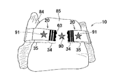
図12は、さらに他の実施例の一例における図8(b)と同様の図である。本実施例に係るおむつ10では、第2部分85の外面に星柄の中央表示要素(表示要素)90が配置されている。一対のテープタブ20の第2表示域35は表示要素90と同形同大の星柄からなる第2表示要素(側方表示要素)91を有する第2表示域35が配置されており、一対のテープタブ20を第2部分85の外面に止着した状態において、中央表示要素90の両側に第2表示要素91が位置する。テープタブ20がかかる止着態様を有することによって、それらの表示要素90,91が連関して3つの星柄が並んだデザイン(スリースター)を形成している。このように、テープタブ20の第1表示域34又は第2表示域35の表示要素が、止着された状態において、前後ウエスト域13,14又はクロッチ域15から形成された部分の外面に位置する中央表示要素90と連関して特定の意匠性、観念性又は物語性を有することによって、おむつ10の外観上の装飾性が向上する。   FIG. 12 is a view similar to FIG. 8B in an example of still another embodiment. In the diaper 10 according to the present embodiment, a central display element (display element) 90 of a star pattern is disposed on the outer surface of the second portion 85. A second display area 35 having a second display element (side display element) 91 formed of a star pattern having the same shape and size as the display element 90 is disposed in the second display area 35 of the pair of tape tabs 20. With the tape tab 20 fastened to the outer surface of the second portion 85, the second display element 91 is located on both sides of the central display element 90. By having the tape tab 20 having such a fastening mode, the display elements 90 and 91 are linked to form a three star pattern lined design (three star). Thus, the display elements of the first display area 34 or the second display area 35 of the tape tab 20 are located on the outer surface of the portion formed of the front and rear waist areas 13 and 14 or the crotch area 15 in the fastened state. By having a specific design, an idea or a narrative in conjunction with the central display element 90, the decorativeness on the appearance of the diaper 10 is improved.

本実施例において、中央表示要素90と第2表示要素91とには、各種公知の表示要素を用いることができる。中央表示要素90は、第2部分85の外面に印刷等によって配置される場合のほかに、例えば、防漏シート42に印刷されて被覆シート43を透過しておむつ10の外面から視認されていてもよい。   In the present embodiment, various known display elements can be used for the central display element 90 and the second display element 91. In addition to the case where the central display element 90 is disposed on the outer surface of the second portion 85 by printing or the like, for example, the central display element 90 is printed on the leakproof sheet 42 and transmitted through the cover sheet 43 and viewed from the outer surface of the diaper 10 It is also good.

おむつ10を構成する各構成部材には、特に限定されている場合を除き、本明細書に記載されている材料のほかに、この種の分野において通常用いられている、各種公知の材料を制限なく使用することができる。また、おむつは、本実施形態と異なり、前ウエスト域13と、後ウエスト域14と、クロッチ域15とが一連に延びるパネル部材(シャーシ)から形成された態様であってもよい。本明細書及び特許請求の範囲において、用語「第1」、「第2」及び「第3」は、同種の要素、位置等を単に区別するために用いられている。   In addition to the materials described herein, the various constituent materials that are commonly used in this type of field are limited to the respective constituent members that make up the diaper 10, unless otherwise specified. It can be used without. Further, unlike the present embodiment, the diaper may have an aspect in which the front waist area 13, the rear waist area 14, and the crotch area 15 are formed from a panel member (chassis) extending in series. In the present specification and claims, the terms "first", "second" and "third" are used merely to distinguish similar elements, positions and the like.

以上に記載した本発明は、少なくとも下記事項に整理することができる。   The present invention described above can be summarized at least in the following matters.

肌当接面及び非肌当接面と、前後ウエスト域の一方である第1ウエスト域と他方である第2ウエスト域と、前記第1及び第2ウエスト域の側縁部どうしが互いに接合された側部シーム域と、前記第1ウエスト域の前記非肌当接面に取り付けられたテープタブとを有する使い捨て着用物品において、前記テープタブは、厚さ方向と、前記第1ウエスト域の前記非肌当接面に固定された近位部と、前記近位部と前記厚さ方向において対向する遠位部とを有し、前記遠位部は、内面及び外面と、前記内面に位置する止着域と、前記止着域よりも先端側に位置する摘持部とを有し、前記摘持部の前記外面には、第1表示要素を有する第1表示域が位置し、前記止着域の存在する領域の前記外面には、第2表示要素を有する第2表示域が位置しており、前記第1表示要素と前記第2表示要素とは、互いに表示が異なる。   The skin contact surface and the non-skin contact surface, the first waist region which is one of the front and rear waist regions, the second waist region which is the other, and the side edges of the first and second waist regions are mutually joined. A disposable wear article having a side seam area and a tape tab attached to the non-skin contact surface of the first waist area, wherein the tape tab has a thickness direction and the non-skin area of the first waist area It has a proximal portion fixed to the abutment surface, the proximal portion and a distal portion opposite in the thickness direction, the distal portion being an inner surface and an outer surface, and a fastening located on the inner surface A first display area having a first display element is positioned on the outer surface of the holding portion, and a holding portion positioned on the tip end side of the fixing region; A second display area having a second display element is located on the outer surface of the area where the Serial wherein the first display element and the second display element, the display is different from each other.

上記段落0059に開示した第1発明は、少なくとも下記の実施の形態を含むことができる。下記の実施の形態は、単独又はそれらの組み合わせであってもよい。
(1)縦方向及びそれに交差する横方向をさらに有し、前記第1及び第2ウエスト域は、前記横方向へ弾性的に伸縮可能であって、前記近位部の一部は前記側縁部に固定されており、前記第1及び第2ウエスト域の収縮状態において、前記側部シーム域が前記第1ウエスト域を外側にして前記横方向において湾曲することによって前記近位部の一部も湾曲し、前記摘持部が前記近位部の前記湾曲した部分と離間して前記横方向の外側へ延出する。
(2)前記近位部の一部は、前記側縁部のうちの前記側部シーム域に固定される。
(3)前記テープタブは、前記近位部と前記遠位部との間に位置する中間部をさらに有し、前記近位部は、前記側部シーム域に固定された第1近位部と、前記第1近位部の横方向の内側においてそれと離間して位置する第2近位部とを有し、前記中間部において、前記第1近位部と前記第2近位部との間に位置する、前記第1ウエスト域の側縁部に非固定の離間部分は、前記第1及び第2ウエスト域の収縮状態において、前記厚さ方向の外側へ凸曲した形状を有する。
(4)前記テープタブは、前記近位部と前記遠位部との間に位置する中間部をさらに有し、前記近位部は、前記第1ウエスト域に固定された第1近位部と、前記第1近位部の縦方向の内側においてそれと離間して位置する第2近位部とを有し、前記第1ウエスト域が収縮した状態において前記第1近位部の配置領域の収縮量が前記第2近位部の収縮量よりも大きく、前記中間部において、前記第1近位部と前記第2近位部との間に位置する前記第1ウエスト域に非固定の離間部分は、前記厚さ方向の外側へ凸曲した形状を有する。
(5)前記摘持部と前記止着域との境界近傍には、前記近位部と前記遠位部とを仮止めするための仮止め部が位置する。
(6)前記テープタブの折り畳まれた状態において、前記第1表示要素の総面積が前記第2表示要素の総面積よりも大きく、前記テープタブの展開された状態において、前記第2表示要素の総面積が前記第1表示要素の総面積よりも大きい。
(7)前記第1表示要素が連続的な形状を有し、前記第2表示要素が非連続的な形状を有しており、前記第2表示要素の装飾性が前記第1表示要素の装飾性よりも高い。
(8)前記テープタブを前記非肌当接面に止着した状態において、前記第1及び第2表示要素のうちの一方と前記非肌当接面において視認される表示要素とが連関性を有する。
(9)前記遠位部は、前記摘持部を除く残余部分を有し、前記残余部分の外面全体に前記第2表示域が位置する。
(10)前記テープタブは、前記遠位部を形成する、前記第1及び第2表示域が配置されたテープ基材をさらに有し、前記テープタブを展開した状態において、前記第2表示域は、前記内面に前記止着域が位置する第1区域と、前記第1区域と隣接する第2区域と、前記近位部側に位置し、かつ、前記テープ基材とは別体のシートが前記外面に配置された第3区域とを有し、前記各区域における前記第2表示要素の視認性の相関関係が、第1区域>第2区域>第3区域である。
The first invention disclosed in the above paragraph 0059 can include at least the following embodiments. The following embodiments may be alone or a combination thereof.
(1) It further has a longitudinal direction and a transverse direction crossing it, and the first and second waist regions are elastically stretchable in the transverse direction, and a part of the proximal portion is the side edge A portion of the proximal portion by being curved in the lateral direction with the first waist region outboard in a contracted state of the first and second waist regions. It is also curved, and the knob extends outward in the lateral direction, spaced apart from the curved portion of the proximal portion.
(2) A portion of the proximal portion is secured to the side seam area of the side edge.
(3) The tape tab further includes an intermediate portion located between the proximal portion and the distal portion, the proximal portion being a first proximal portion fixed to the side seam area A second proximal portion located laterally inward of the first proximal portion and spaced apart from the first proximal portion, and between the first proximal portion and the second proximal portion at the intermediate portion In the contraction state of the first and second waist regions, the separated portion which is not fixed to the side edge portion of the first waist region, which is positioned in the second embodiment, has a shape convex outward in the thickness direction.
(4) The tape tab further includes an intermediate portion located between the proximal portion and the distal portion, the proximal portion being a first proximal portion fixed to the first waist region And a second proximal portion spaced apart therefrom at a longitudinally inner side of the first proximal portion, wherein the contraction of the arrangement region of the first proximal portion in a contracted state of the first waist region A non-fixed spaced portion in the first waist region, wherein the amount is greater than the amount of contraction of the second proximal portion, and in the middle portion between the first proximal portion and the second proximal portion Has a shape that is convex outward in the thickness direction.
(5) A temporary fixing portion for temporarily fixing the proximal portion and the distal portion is located in the vicinity of the boundary between the grip portion and the fastening area.
(6) In the folded state of the tape tab, the total area of the first display element is greater than the total area of the second display element, and in the expanded state of the tape tab, the total area of the second display element Is larger than the total area of the first display element.
(7) The first display element has a continuous shape, the second display element has a non-continuous shape, and the decorativeness of the second display element is the decoration of the first display element Higher than sex.
(8) In the state where the tape tab is fixed to the non-skin contact surface, one of the first and second display elements has an association with the display element visually recognized on the non-skin contact surface .
(9) The distal portion has a remaining portion excluding the grip portion, and the second display area is located on the entire outer surface of the remaining portion.
(10) The tape tab further includes a tape base on which the first and second display areas are disposed, the tape tab forming the distal portion, and in the state where the tape tab is expanded, the second display area is: A first area where the fastening area is located on the inner surface, a second area adjacent to the first area, and the proximal side, and a sheet separate from the tape substrate is the sheet And a third area disposed on the outer surface, wherein the correlation of visibility of the second display element in each area is: first area> second area> third area.

10 使い捨ておむつ(使い捨て着用物品)
13 前ウエスト域(第1又は第2ウエスト域)
14 後ウエスト域(第1又は第2ウエスト域)
18 後ウエスト域の側縁部(第1ウエスト域の側縁部)
20 テープタブ
21 近位部
21A 第1近位部
21B 第2近位部
22 遠位部
34 第1表示域
34a 第1表示要素
35 第2表示域
35a 第2表示要素
51 第1テープ基材
52 第2テープ基材
56a 折曲部(第1折曲部)
57a 折曲部(第2折曲部)
64 残余部分
64A 第1区域
64B 第2区域
64C 第3区域
65,66 仮止め部
68 止着域
77 離間部分
61 中間部
63 摘持部
68 止着域
X 横方向
Y 縦方向
Z 厚さ方向
10 Disposable diapers (disposable items)
13 Front waist area (first or second waist area)
14 rear waist area (first or second waist area)
18 Side edge of back waist area (side edge of first waist area)
Reference Signs List 20 tape tab 21 proximal portion 21A first proximal portion 21B second proximal portion 22 distal portion 34 first display area 34a first display element 35 second display area 35a second display element 51 first tape base 52 second 2 Tape base material 56a bent portion (first bent portion)
57a bent part (second bent part)
64 Remaining part 64A 1st area 64B 2nd area 64C 3rd area 65, 66 Temporary fixing part 68 Fastening area 77 Separation area 61 Intermediate part 63 Picking area 68 Fastening area X Horizontal direction Y Longitudinal direction Z Thickness direction

Claims (11)

肌当接面及び非肌当接面と、前後ウエスト域の一方である第1ウエスト域と他方である第2ウエスト域と、前記第1及び第2ウエスト域の側縁部どうしが互いに接合された側部シーム域と、前記第1ウエスト域の前記非肌当接面に取り付けられたテープタブとを有する使い捨て着用物品において、
前記テープタブは、厚さ方向と、前記第1ウエスト域の前記非肌当接面に固定された近位部と、前記近位部と前記厚さ方向において対向する遠位部とを有し、
前記遠位部は、内面及び外面と、前記内面に位置する止着域と、前記止着域よりも先端側に位置する摘持部とを有し、
前記摘持部の前記外面には、第1表示要素を有する第1表示域が位置し、前記止着域の存在する領域の前記外面には、第2表示要素を有する第2表示域が位置しており、前記第1表示要素と前記第2表示要素とは、互いに表示が異なることを特徴とする前記着用物品。
The skin contact surface and the non-skin contact surface, the first waist region which is one of the front and rear waist regions, the second waist region which is the other, and the side edges of the first and second waist regions are mutually joined. A disposable wear article having a side seam area and a tape tab attached to the non-skin bearing surface of the first waist area;
The tape tab has a thickness direction, a proximal portion fixed to the non-skin contact surface of the first waist region, and a distal portion facing the proximal portion in the thickness direction.
The distal portion has an inner surface and an outer surface, a fastening region located on the inner surface, and a knob located distal to the fastening region,
A first display area having a first display element is located on the outer surface of the grip portion, and a second display area having a second display element is located on the outer surface of the area where the fastening area is present And the first display element and the second display element are different in display from each other.
縦方向及びそれに交差する横方向をさらに有し、前記第1及び第2ウエスト域は、前記横方向へ弾性的に伸縮可能であって、前記近位部の一部は前記側縁部に固定されており、前記第1及び第2ウエスト域の収縮状態において、前記側部シーム域が前記第1ウエスト域を外側にして前記横方向において湾曲することによって前記近位部の一部も湾曲し、前記摘持部が前記近位部の前記湾曲した部分と離間して前記横方向の外側へ延出する請求項1に記載の着用物品。   It further has a longitudinal direction and a transverse direction intersecting it, and the first and second waist regions are elastically stretchable in the transverse direction, and a part of the proximal portion is fixed to the side edge And in the contracted state of the first and second waist zones, the side seam zones are curved in the lateral direction with the first waist zone outwards, so that a portion of the proximal portion is also bowed The wear article according to claim 1, wherein the grip portion extends outward in the lateral direction at a distance from the curved portion of the proximal portion. 前記近位部の一部は、前記側縁部のうちの前記側部シーム域に固定される請求項1又は2に記載の着用物品。 The wearing article according to claim 1, wherein a part of the proximal portion is fixed to the side seam area of the side edge. 前記テープタブは、前記近位部と前記遠位部との間に位置する中間部をさらに有し、前記近位部は、前記側部シーム域に固定された第1近位部と、前記第1近位部の横方向の内側においてそれと離間して位置する第2近位部とを有し、前記中間部において、前記第1近位部と前記第2近位部との間に位置する、前記第1ウエスト域の側縁部に非固定の離間部分は、前記第1及び第2ウエスト域の収縮状態において、前記厚さ方向の外側へ凸曲した形状を有する請求項2又は3に記載の着用物品。 The tape tab further includes an intermediate portion located between the proximal portion and the distal portion, the proximal portion including a first proximal portion secured to the side seam area; (I) a second proximal portion located inward in the lateral direction of the proximal portion and spaced apart therefrom, and located between the first proximal portion and the second proximal portion in the middle portion; The separated portion which is not fixed to the side edge portion of the first waist region has a shape convex outward in the thickness direction in a contracted state of the first and second waist regions. Wearing item as described. 前記テープタブは、前記近位部と前記遠位部との間に位置する中間部をさらに有し、前記近位部は、前記第1ウエスト域に固定された第1近位部と、前記第1近位部の縦方向の内側においてそれと離間して位置する第2近位部とを有し、前記第1ウエスト域が収縮した状態において前記第1近位部の配置領域の収縮量が前記第2近位部の収縮量よりも大きく、前記中間部において、前記第1近位部と前記第2近位部との間に位置する前記第1ウエスト域に非固定の離間部分は、前記厚さ方向の外側へ凸曲した形状を有する請求項1に記載の着用物品。 The tape tab further includes an intermediate portion located between the proximal portion and the distal portion, the proximal portion including a first proximal portion fixed to the first waist region, and A second proximal portion spaced apart from the first in the longitudinal direction of the proximal portion, and in a contracted state of the first waist region, the amount of contraction of the arrangement region of the first proximal portion is A non-fixed spaced portion, which is larger than the amount of contraction of the second proximal portion, and which is not fixed to the first waist region located between the first proximal portion and the second proximal portion in the middle portion, The wearing article according to claim 1 having a shape which is convexly curved outward in the thickness direction. 前記摘持部と前記止着域との境界近傍には、前記近位部と前記遠位部とを仮止めするための仮止め部が位置する請求項1〜5のいずれかに記載の着用物品。   The wear according to any one of claims 1 to 5, wherein a temporary fixing portion for temporarily fixing the proximal portion and the distal portion is located in the vicinity of the boundary between the grip portion and the fastening area. Goods. 前記テープタブの折り畳まれた状態において、前記第1表示要素の総面積が前記第2表示要素の総面積よりも大きく、前記テープタブの展開された状態において、前記第2表示要素の総面積が前記第1表示要素の総面積よりも大きい請求項1〜6のいずれかに記載の着用物品。 In the folded state of the tape tab, the total area of the first display element is larger than the total area of the second display element, and in the expanded state of the tape tab, the total area of the second display element is the second The wearing article according to any one of claims 1 to 6, which is larger than the total area of one display element. 前記第1表示要素が連続的な形状を有し、前記第2表示要素が非連続的な形状を有しており、前記第2表示要素の装飾性が前記第1表示要素の装飾性よりも高い請求項1〜7のいずれかに記載の着用物品。   The first display element has a continuous shape, the second display element has a non-continuous shape, and the decorativeness of the second display element is more than the decorativeness of the first display element The wearing article according to any one of claims 1 to 7, which is high. 前記テープタブを前記非肌当接面に止着した状態において、前記第1及び第2表示要素のうちの一方と前記非肌当接面において視認される表示要素とが連関性を有する請求項1〜8のいずれかに記載の着用物品。   In the state where the tape tab is fixed to the non-skin contact surface, one of the first and second display elements and the display element visually recognized on the non-skin contact surface have an association. The wearing article in any one of -8. 前記遠位部は、前記摘持部を除く残余部分を有し、前記残余部分の外面全体に前記第2表示域が位置する請求項1〜9のいずれかに記載の着用物品。 The wearing article according to any one of claims 1 to 9, wherein the distal portion has a remaining portion excluding the grip, and the second display area is located on the entire outer surface of the remaining portion. 前記テープタブは、前記遠位部を形成する、前記第1及び第2表示域が配置されたテープ基材をさらに有し、前記テープタブを展開した状態において、前記第2表示域は、前記内面に前記止着域が位置する第1区域と、前記第1区域と隣接する第2区域と、前記近位部側に位置し、かつ、前記テープ基材とは別体のシートが前記外面に配置された第3区域とを有し、前記各区域における前記第2表示要素の視認性の相関関係が、第1区域>第2区域>第3区域である請求項10に記載の着用物品。   The tape tab further includes a tape base on which the first and second display areas are disposed, the tape tab forming the distal portion, and in the state where the tape tab is expanded, the second display area is on the inner surface A first area where the fastening area is located, a second area adjacent to the first area, the proximal side, and a sheet separate from the tape substrate is disposed on the outer surface The worn article according to claim 10, further comprising a third area, and a correlation of visibility of the second display element in each area is first area> second area> third area.
JP2015064328A 2015-03-26 2015-03-26 Disposable Wearables Active JP6532725B2 (en)

Priority Applications (2)

Application Number Priority Date Filing Date Title
JP2015064328A JP6532725B2 (en) 2015-03-26 2015-03-26 Disposable Wearables
PCT/JP2016/051307 WO2016152209A1 (en) 2015-03-26 2016-01-18 Disposable article of clothing

Applications Claiming Priority (1)

Application Number Priority Date Filing Date Title
JP2015064328A JP6532725B2 (en) 2015-03-26 2015-03-26 Disposable Wearables

Publications (2)

Publication Number Publication Date
JP2016182257A JP2016182257A (en) 2016-10-20
JP6532725B2 true JP6532725B2 (en) 2019-06-19

Family

ID=56977224

Family Applications (1)

Application Number Title Priority Date Filing Date
JP2015064328A Active JP6532725B2 (en) 2015-03-26 2015-03-26 Disposable Wearables

Country Status (2)

Country Link
JP (1) JP6532725B2 (en)
WO (1) WO2016152209A1 (en)

Families Citing this family (3)

* Cited by examiner, † Cited by third party
Publication number Priority date Publication date Assignee Title
JP6762985B2 (en) * 2018-04-24 2020-09-30 花王株式会社 Pants type disposable diaper
JP2021137197A (en) * 2020-03-03 2021-09-16 ユニ・チャーム株式会社 Absorbent article
JP7439618B2 (en) * 2020-03-31 2024-02-28 王子ホールディングス株式会社 absorbent articles

Family Cites Families (6)

* Cited by examiner, † Cited by third party
Publication number Priority date Publication date Assignee Title
JPS59112005A (en) * 1982-12-15 1984-06-28 ユニ・チャ−ム株式会社 Clamp piece
JP4336540B2 (en) * 2002-08-30 2009-09-30 ユニ・チャーム株式会社 Pants-type disposable diapers
JP4090913B2 (en) * 2003-02-28 2008-05-28 大王製紙株式会社 Absorbent articles
CA2708725C (en) * 2010-07-27 2013-01-22 The Procter & Gamble Company Absorbent article having fastening members with indicium
JP2013198693A (en) * 2012-03-26 2013-10-03 Oji Holdings Corp Tape type diaper and method for manufacturing tape type diaper
JP5980054B2 (en) * 2012-08-31 2016-08-31 ユニ・チャーム株式会社 Disposable pants-type wearing articles

Also Published As

Publication number Publication date
JP2016182257A (en) 2016-10-20
WO2016152209A1 (en) 2016-09-29

Similar Documents

Publication Publication Date Title
JP4493315B2 (en) Fastening elements and disposable diapers
US20080114322A1 (en) Body panel for an adjustable pant-like disposable undergarment and the undergarment itself
US9724251B2 (en) Refastenable absorbent article
KR102208903B1 (en) Pull-on clothing article
JP2008511416A (en) Absorbent article having a telescopic waist
JP6168855B2 (en) Disposable wearing items
US20110173796A1 (en) Refastenable Absorbent Article
JP6532725B2 (en) Disposable Wearables
JP6274977B2 (en) Disposable wearing items
KR102686113B1 (en) absorbent article
JP5972746B2 (en) Absorbent package
KR100619552B1 (en) Disposable wearing article with tape fastener
JP6278710B2 (en) Disposable pants-type wearing articles
US20120311771A1 (en) Pant-type wearing article
WO2013047152A1 (en) Disposable diaper
JP6495710B2 (en) Disposable wearing items
JP5906045B2 (en) Disposable wearing items
JP2014147481A (en) Individual package of absorbent article
JP7321494B2 (en) disposable absorbent article
JP7122146B2 (en) absorbent article
JP7524445B1 (en) Pants-type absorbent article
JP6453145B2 (en) Disposable wearing articles
JP6198610B2 (en) Disposable pants-type wearing articles
JP2020048935A (en) Absorbent article and method for using absorbent article

Legal Events

Date Code Title Description
A621 Written request for application examination

Free format text: JAPANESE INTERMEDIATE CODE: A621

Effective date: 20170810

A131 Notification of reasons for refusal

Free format text: JAPANESE INTERMEDIATE CODE: A131

Effective date: 20181009

A521 Request for written amendment filed

Free format text: JAPANESE INTERMEDIATE CODE: A523

Effective date: 20181204

TRDD Decision of grant or rejection written
A01 Written decision to grant a patent or to grant a registration (utility model)

Free format text: JAPANESE INTERMEDIATE CODE: A01

Effective date: 20190423

A61 First payment of annual fees (during grant procedure)

Free format text: JAPANESE INTERMEDIATE CODE: A61

Effective date: 20190522

R150 Certificate of patent or registration of utility model

Ref document number: 6532725

Country of ref document: JP

Free format text: JAPANESE INTERMEDIATE CODE: R150

R250 Receipt of annual fees

Free format text: JAPANESE INTERMEDIATE CODE: R250

R250 Receipt of annual fees

Free format text: JAPANESE INTERMEDIATE CODE: R250

R250 Receipt of annual fees

Free format text: JAPANESE INTERMEDIATE CODE: R250