JP6532535B2 - Seat pan and seat - Google Patents
Seat pan and seat Download PDFInfo
- Publication number
- JP6532535B2 JP6532535B2 JP2017537927A JP2017537927A JP6532535B2 JP 6532535 B2 JP6532535 B2 JP 6532535B2 JP 2017537927 A JP2017537927 A JP 2017537927A JP 2017537927 A JP2017537927 A JP 2017537927A JP 6532535 B2 JP6532535 B2 JP 6532535B2
- Authority
- JP
- Japan
- Prior art keywords
- pan
- sheet
- seat
- seat pan
- sheet pan
- Prior art date
- Legal status (The legal status is an assumption and is not a legal conclusion. Google has not performed a legal analysis and makes no representation as to the accuracy of the status listed.)
- Expired - Fee Related
Links
- 239000002131 composite material Substances 0.000 claims description 24
- 229920001169 thermoplastic Polymers 0.000 claims description 13
- 239000004416 thermosoftening plastic Substances 0.000 claims description 13
- 239000000835 fiber Substances 0.000 claims description 7
- 239000003365 glass fiber Substances 0.000 claims description 7
- 229920000049 Carbon (fiber) Polymers 0.000 claims description 6
- 239000004952 Polyamide Substances 0.000 claims description 6
- 239000004917 carbon fiber Substances 0.000 claims description 6
- 229920002647 polyamide Polymers 0.000 claims description 6
- 230000037303 wrinkles Effects 0.000 claims description 5
- VNWKTOKETHGBQD-UHFFFAOYSA-N methane Chemical compound C VNWKTOKETHGBQD-UHFFFAOYSA-N 0.000 claims description 3
- 230000002093 peripheral effect Effects 0.000 claims description 3
- OKTJSMMVPCPJKN-UHFFFAOYSA-N Carbon Chemical compound [C] OKTJSMMVPCPJKN-UHFFFAOYSA-N 0.000 claims 1
- 229910052799 carbon Inorganic materials 0.000 claims 1
- 238000004519 manufacturing process Methods 0.000 description 7
- 239000000463 material Substances 0.000 description 7
- 239000002184 metal Substances 0.000 description 5
- 238000000465 moulding Methods 0.000 description 4
- 230000005484 gravity Effects 0.000 description 3
- 238000000034 method Methods 0.000 description 3
- 229920002430 Fibre-reinforced plastic Polymers 0.000 description 2
- 229920006097 Ultramide® Polymers 0.000 description 2
- 238000013461 design Methods 0.000 description 2
- 238000009826 distribution Methods 0.000 description 2
- 239000011151 fibre-reinforced plastic Substances 0.000 description 2
- 238000012545 processing Methods 0.000 description 2
- 230000002787 reinforcement Effects 0.000 description 2
- 229910000831 Steel Inorganic materials 0.000 description 1
- 238000010521 absorption reaction Methods 0.000 description 1
- 238000013459 approach Methods 0.000 description 1
- 230000015572 biosynthetic process Effects 0.000 description 1
- 235000008429 bread Nutrition 0.000 description 1
- 239000011199 continuous fiber reinforced thermoplastic Substances 0.000 description 1
- 238000005520 cutting process Methods 0.000 description 1
- 238000011161 development Methods 0.000 description 1
- 230000000694 effects Effects 0.000 description 1
- 239000006260 foam Substances 0.000 description 1
- 238000007731 hot pressing Methods 0.000 description 1
- 230000001788 irregular Effects 0.000 description 1
- 238000005304 joining Methods 0.000 description 1
- 238000012986 modification Methods 0.000 description 1
- 230000004048 modification Effects 0.000 description 1
- 238000003825 pressing Methods 0.000 description 1
- 230000003014 reinforcing effect Effects 0.000 description 1
- 238000010008 shearing Methods 0.000 description 1
- 239000010959 steel Substances 0.000 description 1
- 239000004753 textile Substances 0.000 description 1
- 239000012815 thermoplastic material Substances 0.000 description 1
- 238000003466 welding Methods 0.000 description 1
Images


Classifications
-
- B—PERFORMING OPERATIONS; TRANSPORTING
- B60—VEHICLES IN GENERAL
- B60N—SEATS SPECIALLY ADAPTED FOR VEHICLES; VEHICLE PASSENGER ACCOMMODATION NOT OTHERWISE PROVIDED FOR
- B60N2/00—Seats specially adapted for vehicles; Arrangement or mounting of seats in vehicles
- B60N2/68—Seat frames
-
- A—HUMAN NECESSITIES
- A47—FURNITURE; DOMESTIC ARTICLES OR APPLIANCES; COFFEE MILLS; SPICE MILLS; SUCTION CLEANERS IN GENERAL
- A47C—CHAIRS; SOFAS; BEDS
- A47C7/00—Parts, details, or accessories of chairs or stools
- A47C7/02—Seat parts
- A47C7/029—Seat parts of non-adjustable shape adapted to a user contour or ergonomic seating positions
-
- A—HUMAN NECESSITIES
- A61—MEDICAL OR VETERINARY SCIENCE; HYGIENE
- A61G—TRANSPORT, PERSONAL CONVEYANCES, OR ACCOMMODATION SPECIALLY ADAPTED FOR PATIENTS OR DISABLED PERSONS; OPERATING TABLES OR CHAIRS; CHAIRS FOR DENTISTRY; FUNERAL DEVICES
- A61G5/00—Chairs or personal conveyances specially adapted for patients or disabled persons, e.g. wheelchairs
- A61G5/10—Parts, details or accessories
- A61G5/12—Rests specially adapted therefor, e.g. for the head or the feet
- A61G5/122—Rests specially adapted therefor, e.g. for the head or the feet for the back
-
- B—PERFORMING OPERATIONS; TRANSPORTING
- B60—VEHICLES IN GENERAL
- B60N—SEATS SPECIALLY ADAPTED FOR VEHICLES; VEHICLE PASSENGER ACCOMMODATION NOT OTHERWISE PROVIDED FOR
- B60N2/00—Seats specially adapted for vehicles; Arrangement or mounting of seats in vehicles
- B60N2/24—Seats specially adapted for vehicles; Arrangement or mounting of seats in vehicles for particular purposes or particular vehicles
- B60N2/38—Seats specially adapted for vehicles; Arrangement or mounting of seats in vehicles for particular purposes or particular vehicles specially constructed for use on tractors or like off-road vehicles
-
- B—PERFORMING OPERATIONS; TRANSPORTING
- B60—VEHICLES IN GENERAL
- B60N—SEATS SPECIALLY ADAPTED FOR VEHICLES; VEHICLE PASSENGER ACCOMMODATION NOT OTHERWISE PROVIDED FOR
- B60N2/00—Seats specially adapted for vehicles; Arrangement or mounting of seats in vehicles
- B60N2/64—Back-rests or cushions
- B60N2/646—Back-rests or cushions shape of the cushion
-
- B—PERFORMING OPERATIONS; TRANSPORTING
- B60—VEHICLES IN GENERAL
- B60N—SEATS SPECIALLY ADAPTED FOR VEHICLES; VEHICLE PASSENGER ACCOMMODATION NOT OTHERWISE PROVIDED FOR
- B60N2/00—Seats specially adapted for vehicles; Arrangement or mounting of seats in vehicles
- B60N2/68—Seat frames
- B60N2/682—Joining means
- B60N2002/684—Joining means the back rest being mounted or joined with an easy attachment system to the seat
-
- B—PERFORMING OPERATIONS; TRANSPORTING
- B60—VEHICLES IN GENERAL
- B60N—SEATS SPECIALLY ADAPTED FOR VEHICLES; VEHICLE PASSENGER ACCOMMODATION NOT OTHERWISE PROVIDED FOR
- B60N2205/00—General mechanical or structural details
- B60N2205/30—Seat or seat parts characterised by comprising plural parts or pieces
Description
本発明は、自動車部品の技術分野、具体的には車両の内装品であるシートパン、及びそのシートパンを有する座席に関する。 The present invention relates to the technical field of automobile parts, in particular to a seat pan which is an interior part of a vehicle and a seat having the seat pan.
自動車の開発にあっては、車両座席のシートパンフレームは最も重要な保安部品の1つである。一般的に、現在、よく使われている座席のシートパンフレームは、打ち抜き成形又は加圧成形及び鋳込み成形した板金を溶接によって統合して形成される。この板金形成のシートパンは、高い強度を示すが、非常に重いため、重量制限に起因して板金の使用可能範囲が制限され、それは、シートパンの寸法も同様に制限されることを意味する。 In the development of automobiles, the seat pan frame of the vehicle seat is one of the most important safety parts. Generally, the seat pan frame of the seat currently used is formed integrally by welding stamped or pressed and cast sheet metal. This sheet metal forming sheet pan exhibits high strength but is very heavy, which limits the usable range of sheet metal due to weight limitations, which means that the size of the sheet pan is also limited. .
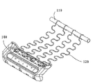
快適性を改善するためのしなやかでかつ軽量なシートパンが創案されており、例えば中国実用新案CN203410340U及びCN202368420Uに開示される。図8を参照すると、このしなやかなシートパンは、前部支持板金100、前部支持板金と平行な後部補強チューブ110、及びそれらの間に結合された複数のスプリング120を含む。この前部支持板金は座席のセミパン(semi-pan)を形成し、曲がりくねったスプリングは、座席快適性を改善するためのしなやかさを提供するために、シートパンの後半部に位置されている。
A flexible and lightweight seat pan has been devised for improving the comfort and is disclosed, for example, in Chinese utility models CN203410340U and CN202368420U. Referring to FIG. 8, the flexible seat pan includes a
しかしながら、このシートパン構造は、以下の欠点を被り得る、即ち:スプリングと前部支持板金を結合するための付加的な締結手段が必要とされる、またアッセンブリ工程が非常に複雑である;このシートパン構造が、非常に短い時間の使用にも関わらず、硬い道によってもたらされる連続的な衝撃に耐えることができないためにスプリングは弾性を損なうか又は破損の影響を受けやすく、その結果、着座快適性は悪化し且つ耐用年数が短くなる。 However, this seat pan structure can suffer from the following disadvantages: additional fastening means are required for joining the spring and the front support plate, and the assembly process is very complicated; Due to the inability of the seat pan structure to withstand the continuous impact provided by the hard path despite the very short time of use, the spring is susceptible to elasticity or is susceptible to breakage, resulting in seating The comfort is worse and the service life is shorter.
従って、軽量で、着座者の重みを支持するための十分な強度を提供することができ、製造工程が簡易で、組立時間を短縮し、且つ完璧な着座快適性を示すシートパン構造の開発が要求される。 Therefore, it is possible to develop a seat pan structure that is lightweight, can provide sufficient strength to support the weight of the seat occupant, can simplify the manufacturing process, shorten the assembly time, and exhibit perfect seating comfort. Required
本発明の目的は、軽量で、且つ座席上の乗員の重みに耐え且つ衝撃エネルギーを吸収することができ、製造工程が簡易で、組み立て時間を短縮し且つ着座快適性に関して改善するシートパン構造を提供することにある。 The object of the present invention is a seat pan structure which is lightweight, able to withstand the weight of the occupant on the seat and absorb impact energy, which simplifies the manufacturing process, shortens the assembly time and improves the seating comfort. It is to provide.
本発明の1つの形態に関し、第1熱可塑性複合材料で1つのパンに形成されたシートパンが提供され、そのシートパンは重み負荷部を有し、そのシートパンの重み負荷部の領域に少なくとも1つのスロットが設けられ、またスロットで区分されたストラップの側縁上にオーバーモールド成形によって形成された被覆帯がストラップを補強するようにスロットの周縁の少なくとも一部に沿って延伸し、被覆帯は第2熱可塑性複合材料からなる。複合材料の利用によって、シートパンの重さが低減され、また柔らかな挙動を与えるストラップを一体のシートパンに機能的に組み込むことにより、弾性機能が付与されると同時に組立時間を短縮することができ、またストラップの側縁上の被覆帯のおかげで、ストラップの剛性を増加すると共にストラップの弾性係数を調整することができる。それと同時に、このようなシートパンは、乗員の重みに耐え且つ衝撃エネルギーを吸収することに十分に機能できる。 According to one aspect of the present invention, there is provided a seat pan formed in one pan of a first thermoplastic composite material, the seat pan having a weight loading portion, at least in the area of the weight loading portion of the sheet pan. A covering band formed by overmolding on a side edge of the slotted strap provided with one slot extends along at least a part of the periphery of the slot so as to reinforce the strap, and the covering band Is made of a second thermoplastic composite material. The use of composite materials reduces the weight of the seat pan and also functionally integrates the straps giving a soft behavior into an integral seat pan, thus providing an elastic function and at the same time reducing the assembly time It is possible, and thanks to the covering bands on the side edges of the strap, it is possible to increase the stiffness of the strap and to adjust the elastic modulus of the strap. At the same time, such a seat pan can function sufficiently to withstand occupant weight and absorb impact energy.
好ましくは、溝及び/又は突起を備える少なくとも1つの波形しわがストラップ上に設けられる。好ましくは、その溝及び/又は突起は、シートパンの左右方向に沿って延伸する。 Preferably, at least one corrugated crease comprising grooves and / or protrusions is provided on the strap. Preferably, the grooves and / or protrusions extend along the lateral direction of the seat pan.
好ましくは、シートパンの重み負荷部の前後端に波形しわが設けられる。これは、シートパンに負荷がかかったときに、シートパンの重み負荷部の前後端が変形しやすいことに起因する。また、そうすることで、ストラップの耐久性が高まる。 Preferably, corrugated creases are provided at the front and rear ends of the weight loading portion of the seat pan. This results from the fact that when a load is applied to the sheet pan, the front and rear ends of the weight load portion of the sheet pan are easily deformed. Also, doing so increases the durability of the strap.
好ましくは、シートパンの重み負荷部の後端における波形しわと比較して、シートパンの重み負荷部の前端における波形しわは高い密度で形成される。この構成のゆえに、シートパンの局所的な変形が効果的に回避される。ここでは、密度は、単位長当たりの溝及び/又は突起の数を意味する。 Preferably, the corrugated creases at the front end of the weight load of the seat pan are formed with a higher density compared to the corrugated creases at the rear end of the weight load of the seat pan. Due to this configuration, local deformation of the seat pan is effectively avoided. Here, density means the number of grooves and / or protrusions per unit length.
好ましくは、少なくとも1つのスロットは、シートパンの前後方向に延伸する。同様に、被覆帯はシートパンの前後方向に延伸する。この構成のゆえに、制御された態様で剛性と柔軟性を提供することができ、即ち十分な強度と着座快適性を同時に提供することができる。 Preferably, at least one slot extends in the front-rear direction of the seat pan. Similarly, the coated band extends in the front-rear direction of the sheet pan. Because of this configuration, stiffness and flexibility can be provided in a controlled manner, ie sufficient strength and seating comfort can be provided simultaneously.
好ましくは、被覆帯の上面は、対応するストラップの上面と同じ高さである。一般的に、発泡マットのようなマットが、シートパンの上面に配置される。被覆帯の上面が対応するストラップの上面と同じ高さであるという構成によって、被覆帯がストラップの弾性係数を有利に制御することが許容される。好ましくは、この被覆帯はL字形断面を有する。 Preferably, the upper surface of the covering band is flush with the upper surface of the corresponding strap. Generally, a mat, such as a foam mat, is placed on top of the sheet pan. The arrangement that the upper surface of the covering zone is at the same level as the upper surface of the corresponding strap allows the covering zone to advantageously control the elastic modulus of the strap. Preferably, the covering has an L-shaped cross section.
好ましくは、スロットの数は、3〜6の範囲である。スロットの数が多ければ、シートパンにはより柔らかさが提供される。しかしながら、構造強度の点でシートパンには、より多くの弱点が現れるであろう。従って、柔らかさと強度の双方のバランスを通じて、スロットの数は最適化され得る。 Preferably, the number of slots is in the range of three to six. The greater the number of slots, the softer the sheet pan is provided. However, in terms of structural strength, sheet pans will appear more vulnerable. Thus, through a balance of both softness and strength, the number of slots can be optimized.
好ましくは、少なくとも1つのスロットは、シートパンの後側部にまで及ぶ。設計上、構造的強度が許す限り、より快適性を高めるため、できる限り遠くまでスロットを伸ばすことができる。 Preferably, at least one slot extends to the back side of the seat pan. By design, as far as structural strength permits, the slot can be extended as far as possible to enhance comfort.
好ましくは、重み負荷部の領域における隣接するストラップの部分は、同じ水平面にない。異なる高さのストラップは、緩衝バネとして作動し得、スロットが提供する空間を駆使することによってより多くの被覆帯を提供し得る。 Preferably, the portions of adjacent straps in the area of the weight load are not in the same horizontal plane. Straps of different heights can act as buffer springs and can provide more coverage by taking advantage of the space provided by the slots.
好ましくは、隣接する2つのストラップ間では、より高い水平面内のストラップに1つ以上の波形しわが設けられる。これは、シートパンが使用されているとき、より高い水平面にあるストラップが負荷とその衝撃の大部分を最初に受けるためである。 Preferably, between two adjacent straps, the straps in the higher horizontal plane are provided with one or more corrugated creases. This is because when the seat pan is in use, the straps in the higher horizontal plane will receive most of the load and its impact first.
好ましくは、被覆帯はスロットの全周縁に沿って延伸する。この構成のゆえに、着座者の重みを支持するための十分な強度を有するように、スロットの全周縁に沿ってストラップが補強される。 Preferably, the covering extends along the entire periphery of the slot. Because of this configuration, the straps are reinforced along the entire perimeter of the slot so as to have sufficient strength to support the seat occupant's weight.
好ましくは、第1熱可塑性複合材料は、織物形態の二方向連続繊維、好ましくはガラス繊維又は炭素繊維で強化されたポリアミドであってよい。この材料は、低比重且つ高強度で、それ故にシートパンとして好ましい選択である。 Preferably, the first thermoplastic composite material may be a bi-directional continuous fiber in woven form, preferably a glass fiber or carbon fiber reinforced polyamide. This material is a low specific gravity and high strength and hence a preferred choice for a sheet pan.
好ましくは、第2熱可塑性複合材料は、好ましくはガラス繊維又は炭素繊維で、その繊維の長さは0.1〜1.2mm、好ましくは0.2〜0.4mmの範囲である繊維で強化されたポリアミドであってよい。こうした材料からなる被覆帯は、シートパンが提供する柔らかさの制御/調整に用いることができる。 Preferably, the second thermoplastic composite material is reinforced with fibers, preferably glass fibers or carbon fibers, the length of which is in the range of 0.1 to 1.2 mm, preferably 0.2 to 0.4 mm. It may be a polyamide. Covering bands made of such materials can be used to control / adjust the softness provided by the sheet pan.
好ましくは、シートパンを補強するようにシートパンの周辺縁の少なくとも一部の上に、第2熱可塑性複合材料のオーバーモールド成形によって別の被覆帯が形成される。 Preferably, another covering band is formed by overmolding of the second thermoplastic composite material on at least a portion of the peripheral edge of the sheet pan to reinforce the sheet pan.
本発明の第2の形態に関し、上述のシートパンを備える座席が提供される。 According to a second aspect of the present invention there is provided a seat comprising a seat pan as described above.
本発明では、軽く、着座者の重みを支持するのに十分な強度のシートパンが作られ得る。更に、製造コストの低減、組み立て時間の減少、及び着座快適性の改善と共に、製造工程が簡易である。 In the present invention, a seat pan can be made which is light and strong enough to support the weight of the seat occupant. Furthermore, the manufacturing process is simplified with reduced manufacturing costs, reduced assembly time and improved seating comfort.
以下の実施の形態は、実施の形態の例が描かれている図面を参照して説明される。同等又は類似する構成要素が描かれる図面を通じ、なるべく、同じ参照番号が使用される。 The following embodiments are described with reference to the drawings in which examples of the embodiments are depicted. Preferably, the same reference numerals are used throughout the drawings in which similar or similar components are drawn.
図1は、背もたれ10及びシートパン20を備えた本発明の座席1の全体図である。一般的に、支持構造アッセンブリ及び高さ調整アッセンブリはシートパン20の下方に設けられる。その支持構造アッセンブリは、主として、座席の前後(fore-and-aft)方向に関して前部の支持チューブ、座席の前後方向に関して後部の支持チューブ、及び座席の左右方向に関して左右側の側面支持ラックを備える。
FIG. 1 is a general view of a
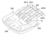
図2に示す実施の形態では、シートパン20は、第1熱可塑性複合材料からなり、例えば熱プレスによってパン形状に一体に形成される。このシートパン20は、夫々の機能性に関して分割された重み負荷部201、左横側部202、右横側部203、前側部204、及び後側部205からなる。その重み負荷部201は、主として、着座者の重みを支持するように構成される。この重み負荷部201は、前側部204から下方に凹み、後側部205に向かって後方へ移行する。後側部205は、重み負荷部201がシートパン20の底領域に実質的に位置するように、重み負荷部201の隣接境界から或る高さ(a level)まで上方に延伸する。
In the embodiment shown in FIG. 2, the
このシートパンのボディに適した複合材料は、板金、特に板金に匹敵する強度を有する鋼よりも低比重を示す。有利には、このシートパンのボディに適した複合材料は、織物形態の二方向連続繊維(例えばガラス繊維又は炭素繊維など)で強化された熱可塑性材料、例えばBASF社製のUltralaminate(登録商標)である。有利には、このパンのボディは、上述した1層の二方向連続繊維強化熱可塑性材料の熱プレスによって形成されてもよい。更に、熱加工による複合材料の成形は簡単であり、型による形状は柔軟に設計することができる(型成形は全く誤りのない1工程で行われる)。例えば、好ましくは左横側部202領域及び右横側部203領域は左右側面支持ラックとの嵌合のため、上方に折り返されたエッジが備わっており、また好ましくはシートパンの後側部205の領域は後支持チューブと連携するための構造(例えば折り返し構造)を有し、また好ましくはシートパンの前側部204も前支持チューブと連携するための構造(例えば折り返し構造)を有する。
Composites suitable for the body of this sheet pan exhibit a lower specific gravity than sheet metal, in particular steel having a strength comparable to sheet metal. Advantageously, the composite material suitable for the body of this sheet pan is a thermoplastic material reinforced with bi-directional continuous fibers (for example glass fibers or carbon fibers etc.) in the form of textiles, for example Ultralaminate® from BASF. It is. Advantageously, the body of the bread may be formed by hot pressing of the one-layer bi-directional continuous fiber reinforced thermoplastic material described above. Furthermore, molding of the composite material by thermal processing is simple, and the shape of the mold can be designed flexibly (the molding takes place in one completely error free process). For example, preferably the
ここでの「前」、「後」、「左」、「右」、「上」、及び「下」という技術用語は、座った状態の姿勢において座席又はシートパンの中央部に対する前後、左右、及び上下方向を指す。事実上、シートパンが成形された時点で、シートパンの姿勢や配置は決定される。 The technical terms “front”, “rear”, “left”, “right”, “upper”, and “lower” in this context refer to the front or back, left or right, relative to the central part of the seat or seat pan in the sitting position And pointing up and down. In fact, when the sheet pan is formed, the posture and arrangement of the sheet pan are determined.
図2及び図3に示す好ましい実施の形態では、このシートパンの重み負荷部は、少なくとも1つのスロット2010を備える。このスロット2010は、細長い溝状の開口である。好ましくは、このスロット2010は、シートパン20の前後方向に延伸する。
In the preferred embodiment shown in FIGS. 2 and 3 the weight loading portion of the seat pan comprises at least one
図2は6つのスロット2010を示しているが、当業者は、スロット2010の数を、3つ、4つ、5つ、又はそれ以上としてよいことや、シートパン20の実際の幅や複合材料の強度特性の機能として設定し得ることを容易に想到し得る。加えて、図では複数のスロットは互いに略平行に延伸して表されているが、当業者は、複数のスロットの延伸方向が互いに平行でなくてもよいことを想到し得る。更に、このスロットは、シートパンの前後方向での延伸に制限されるものでなく、シートパンの左右方向又はその他の方向に延伸してもよい。
Although FIG. 2 shows six
このスロット2010は、より大きな弾性を得るようにシートパン20の後側部205の領域に向かうあらゆる方向に延伸してもよい。好ましくは、このスロット2010は、後側部205の縁と交差しない。
The
図2及び図3に示すように、このスロット2010は、重み負荷部201を1つの形状から両端部が接続されたままの複数のストラップ2011に分割する。被覆帯2012は、ストラップの側縁上にオーバーモールド成形によって形成され且つスロットの周縁の少なくとも一部に沿って、好ましくは、例えば図6に示すように、スロットの全周縁に沿って延伸する。
As shown in FIGS. 2 and 3, the
好ましくは、被覆帯2012は、第2熱可塑性複合材料からなる。好ましくは、第2複合材料は、シートパンのボディ用の第1複合材料とは異なる。この第2複合材料は、ポリアミドであって、例えばBASF社製のUltramid(登録商標)のような、0.1〜1.2mm、好ましくは0.2〜0.4mmの範囲の長さを有する60質量%以下のガラス又は炭素繊維によって補強されたポリアミドであることが好ましい。この被覆帯2012は、ストラップを補強するように構成され、対応するストラップの局所的な剛性や弾性の調整を可能とする。この被覆帯2012の大きさ、断面形状、数や配分は、要求に応じて柔軟に調整することができる。好ましくは、被覆帯2012の上面は、対応するストラップ2011の上面と同じ高さである。この被覆帯2012の断面形状は、例えばL字形、三角形、長方形であってもよい。この被覆帯は、またあらゆる不規則な幾何学形状の断面を有してもよい。
Preferably, the
好ましい実施の形態では、シートパンを全体的に補強するようにシートパンの周辺縁の少なくとも一部の上に、第2熱可塑性複合材料のオーバーモールド成形によって別の被覆帯が形成される。 In a preferred embodiment, another covering band is formed by overmolding of the second thermoplastic composite material on at least a portion of the peripheral edge of the sheet pan so as to generally reinforce the sheet pan.
好ましくは、重み負荷部の領域における隣接する2つのストラップは、同じ水平面にない。例えば、隣接する2つのストラップの鉛直オフセットは5mmである。図3に示すように、シートパンに負荷がかかったときの圧力をより高い水平面内の幾つかのストラップが最初に受け、次に、低い水平面内の幾つかのストラップが、その後にそれらに負荷がかかったときの支持を確保するように、複数のストラップ2011は、シートパンの重み負荷部201の領域内で左右方向に異なる水平面に配置されている。従って、実際のところ、最初に重みがかかるストラップが、それにより、より満足な快適性を提供する確実なクッション機能を有する。
Preferably, two adjacent straps in the area of the weight load are not in the same horizontal plane. For example, the vertical offset of two adjacent straps is 5 mm. As shown in FIG. 3, when the seat pan is loaded, some straps in the higher horizontal surface will first receive the pressure when loaded, then some straps in the lower horizontal surface will load them afterwards The plurality of
図4及び5に示すシートパンに見られるように、シートパン20の重み負荷部201は、人間工学の点からシートパン上に座っている着座者の快適性の要求に合わせることを第一義として、前側部と比較して下方且つ後方に凹んでいる。特に図4から、上段におけるストラップが、ストラップの両端部を滑らかに結合して円弧形に延伸する基線Lから逸脱するように構成されているのを見ることができる。シートパンに負荷がかかったとき、上段におけるストラップは、変形せしめられ且つ側面視で基線Lに近づき、また下段におけるストラップは張力がかかると共に伸ばされ、そして、シートパンの負荷がなくなったとき、全てのストラップは通常位置に復元する。従って、この複数のストラップは、ばねのようにふるまう。
As can be seen in the seat pans shown in FIGS. 4 and 5, the
図4、6、及び7に示す好ましい実施の形態では、幾つかのストラップ2011は、溝2013a及び/又は突起2013bを含む波形しわ2013と共に提供される。好ましくは、この溝2013a及び/又は突起2013bは、シートパンの左右方向に延伸する。好ましくは、この溝2013a及び/又は突起2013bは、対応するストラップの全幅に亘って延伸する。この波形しわ2013は、特にストラップに負荷がかかったときの自身の局所的な変形を防止するためにストラップ2011の強度を増加し得る。好ましくは、この波形しわ2013は、シートパン20の重み負荷部2011領域の前端及び後端に亘って配分される。好ましい実施の形態では、シートパンの重み負荷部の後端領域に配置された波形しわと比較して、シートパンの重み負荷部の前端領域では波形しわが高い密度で設けられる。
In the preferred embodiment shown in FIGS. 4, 6 and 7,
図3、4、及び5に示す好ましい実施の形態では、隣接する2つのストラップ201のうちの一方のみに、1つ以上の波形しわが設けられる。特に、隣接する2つのストラップ間では、高さの高いストラップが少なくとも1つの波形しわを有する。
In the preferred embodiment shown in FIGS. 3, 4 and 5, only one of the two
以下は、本発明のシートパンの製造工程の記述である。 The following is a description of the manufacturing process of the sheet pan of the present invention.
連続(即ち長い)繊維強化ポリマー(例えばBASF社製のUltralaminate(登録商標)材料)を含む複合材料は、シートパンのメインボディを形成するために適切な大きさと形状で提供される。一般的に、この提供された複合材料は、熱加工(インモールド成形)によって、重み負荷部201、左横側部202、右横側部203、前側部204、及び後側部205の輪郭や構成(例えば、左横側部202及び右横側部203の領域内の上向き構造、前側部204の領域内の凹凸補強構造、及び重み負荷部201の領域内の波形しわ)を同時に形成して、一体ボディのパン形状のシートパンに形成される。適切な長さ及び幅のスロット2010は、例えば打ち抜き加工や剪断加工のような切断加工によって、重み負荷部201及び後側部205の領域内の予め決定された位置に形成される。このシートパンの重み負荷部201の領域内のスロットは、適切な度合いの柔らかさ、より高い着座快適性、及び衝撃エネルギーのよりよい吸収効果を提供する。スロットの形成によって得られたストラップ上の波形しわは、ストラップの局所的な変形の防止する、構造の局所的な補強を提供する。
Composite materials comprising continuous (i.e., long) fiber reinforced polymers (e.g., Ultralaminate <(R)> material from BASF) are provided with the appropriate size and shape to form the main body of the sheet pan. Generally, the provided composite material is formed by thermal processing (in-mold molding), and the contours of the
その後、非連続(即ち短い)繊維強化ポリマー材料(例えばBASF社製のUltramid(登録商標)材料)からなる被覆帯2012が、オーバーモールド成形によって、スロットによって区分されたストラップ2011の側縁上に形成される。このようにして形成されたシートパンの重み負荷部は、材料、大きさ、断面形状、及び被覆帯の配分によって変化する剛性及び弾性を有する。従って、このシートパンの適用によって異なる剛性及び弾性が柔軟に設計され得るように、被覆帯の構造設計によってシートパンの局所的な剛性及び弾性を調整することができる。
A
本発明によれば、低比重の複合材料により、重量の点で如何なる制約もなく、シートパンの大きさを要求に応じて設計することができ、それは、必要に応じてシートパンの大きさを大きくすることが可能であることを意味する。加えて、簡易な型成形工程という理由で、付加的な組立工程を免ずることや、時間を節約すること、及び製造コストを低減することが可能である。 According to the present invention, the low specific gravity composite material allows the size of the seat pan to be designed according to requirements without any restrictions in terms of weight, which, if necessary, It means that it is possible to make it larger. In addition, it is possible to avoid additional assembly steps, save time and reduce manufacturing costs because of the simple molding process.
上記叙述は、単に本発明の好ましい実施の形態であり、本発明の範囲から逸脱することなく、当業者の試作を通じて種々の変更及び改良がなされ得ることから、本発明の制限又は限定に用いられるものではない。本発明の要旨及び原理内で行われる如何なる変更、準拠、及び改良も、本発明の保護範囲内に含まれる。本開示及び実施の形態は単に典型であるとみなされるべきであり、本発明の真の範囲は添付される特許請求の範囲及びそれと同等のものによって規定される。 The above description is merely a preferred embodiment of the present invention, and can be used as a limitation or limitation of the present invention as various changes and modifications can be made through trial manufacture by those skilled in the art without departing from the scope of the present invention. It is not a thing. It is intended that any changes, compliances and improvements made within the spirit and principle of the present invention fall within the protection scope of the present invention. The present disclosure and embodiments should be considered as exemplary only, and the true scope of the present invention is defined by the appended claims and equivalents thereof.
1 座席
10 背もたれ
20 シートパン
201 重み負荷部
2010 スロット
2011 ストラップ
2012 被覆帯
2013 波形しわ
2013a 溝
2013b 突起
202 左横側部
203 右横側部
204 前側部
205 後側部
Claims (21)
Applications Claiming Priority (5)
| Application Number | Priority Date | Filing Date | Title |
|---|---|---|---|
| CN201510024410 | 2015-01-16 | ||
| CN201510024410.4 | 2015-01-16 | ||
| CN201520033480.1 | 2015-01-16 | ||
| CN201520033480.1U CN204432458U (en) | 2015-01-16 | 2015-01-16 | Seat basin and there is the seat of this basin |
| PCT/EP2016/050683 WO2016113359A1 (en) | 2015-01-16 | 2016-01-14 | Seat pan and seat |
Publications (3)
| Publication Number | Publication Date |
|---|---|
| JP2018506468A JP2018506468A (en) | 2018-03-08 |
| JP2018506468A5 JP2018506468A5 (en) | 2019-02-28 |
| JP6532535B2 true JP6532535B2 (en) | 2019-06-26 |
Family
ID=55168250
Family Applications (1)
| Application Number | Title | Priority Date | Filing Date |
|---|---|---|---|
| JP2017537927A Expired - Fee Related JP6532535B2 (en) | 2015-01-16 | 2016-01-14 | Seat pan and seat |
Country Status (5)
| Country | Link |
|---|---|
| US (1) | US10308150B2 (en) |
| EP (1) | EP3245099B1 (en) |
| JP (1) | JP6532535B2 (en) |
| KR (1) | KR102430201B1 (en) |
| WO (1) | WO2016113359A1 (en) |
Families Citing this family (4)
| Publication number | Priority date | Publication date | Assignee | Title |
|---|---|---|---|---|
| DE102017217981A1 (en) * | 2017-10-10 | 2019-04-11 | Bayerische Motoren Werke Aktiengesellschaft | Backrest of a seat |
| EP3505446A1 (en) * | 2017-12-28 | 2019-07-03 | Acondicionamiento Tarrasense | Seat assembly for an airliner |
| EP3647109B1 (en) * | 2018-10-31 | 2021-08-04 | Volvo Car Corporation | Pivot bracket for connecting vehicle seats |
| EP3862221B1 (en) * | 2020-02-04 | 2023-11-29 | Ningbo Geely Automobile Research & Development Co. Ltd. | Full seat pan with tilt function |
Family Cites Families (17)
| Publication number | Priority date | Publication date | Assignee | Title |
|---|---|---|---|---|
| US3549201A (en) * | 1969-04-03 | 1970-12-22 | Ford Motor Co | Multiple contour upholstery panel |
| JPS5588713A (en) * | 1978-12-27 | 1980-07-04 | Tachikawa Spring Co | Sheet for car in synthetic resin |
| JPS6333561Y2 (en) * | 1980-01-29 | 1988-09-07 | ||
| US4892356A (en) * | 1988-07-27 | 1990-01-09 | Chromcraft Furniture Corp. | Chair shell |
| DE4401665C2 (en) * | 1994-01-21 | 1997-08-14 | Daimler Benz Ag | Plastic shell for a motor vehicle seat |
| JPH1175984A (en) * | 1997-09-04 | 1999-03-23 | Futaba Ind Co Ltd | Seat pad supporting body |
| EP1150592B1 (en) * | 1999-02-12 | 2004-04-28 | Schukra of North America Ltd. | Adjustable back support for seats |
| JP2008006620A (en) * | 2006-06-27 | 2008-01-17 | Kasai Kogyo Co Ltd | Automotive interior trim and its manufacturing method |
| DE102009039498A1 (en) * | 2009-07-06 | 2011-01-13 | Volkswagen Ag | Seat shell of a motor vehicle and method for producing a seat shell of a motor vehicle |
| US8590978B2 (en) | 2010-09-15 | 2013-11-26 | Ford Global Technologies, Llc | Ultra-thin seat carrier |
| US8678505B2 (en) * | 2010-12-21 | 2014-03-25 | Tachi-S Co., Ltd. | Seat cushion of vehicle seat |
| CN202368420U (en) | 2011-12-30 | 2012-08-08 | 河北中兴汽车制造有限公司 | Automobile and seat basin skeleton structure thereof |
| DE102012000772A1 (en) * | 2012-01-18 | 2013-07-18 | GM Global Technology Operations LLC (n. d. Gesetzen des Staates Delaware) | Seat shell for motor vehicle, has portions of respective short and long fiber-reinforced plastics, where crossed long fibers of long-fiber-reinforced plastic are extended between mutually opposite edge sides of shell |
| US8919880B2 (en) * | 2012-03-27 | 2014-12-30 | Haworth, Inc. | Flexible seating surface |
| US9161630B2 (en) | 2012-05-25 | 2015-10-20 | Faurecia Automotive Seating, Llc | Deformable seat shell with motion control |
| JP5930304B2 (en) * | 2012-08-07 | 2016-06-08 | スズキ株式会社 | Vehicle seat |
| CN203410340U (en) | 2013-07-31 | 2014-01-29 | 浙江吉俱泰汽车内饰有限公司 | Flexible seat basin of automotive seat |
-
2016
- 2016-01-14 EP EP16700717.8A patent/EP3245099B1/en active Active
- 2016-01-14 KR KR1020177022866A patent/KR102430201B1/en active IP Right Grant
- 2016-01-14 JP JP2017537927A patent/JP6532535B2/en not_active Expired - Fee Related
- 2016-01-14 WO PCT/EP2016/050683 patent/WO2016113359A1/en active Application Filing
- 2016-01-14 US US15/543,869 patent/US10308150B2/en active Active
Also Published As
| Publication number | Publication date |
|---|---|
| EP3245099A1 (en) | 2017-11-22 |
| EP3245099B1 (en) | 2019-04-03 |
| WO2016113359A1 (en) | 2016-07-21 |
| WO2016113359A9 (en) | 2017-09-28 |
| US10308150B2 (en) | 2019-06-04 |
| KR102430201B1 (en) | 2022-08-08 |
| JP2018506468A (en) | 2018-03-08 |
| US20180009352A1 (en) | 2018-01-11 |
| KR20170106412A (en) | 2017-09-20 |
Similar Documents
| Publication | Publication Date | Title |
|---|---|---|
| JP6532535B2 (en) | Seat pan and seat | |
| US9028004B2 (en) | Vehicle seat | |
| CN103287299B (en) | Cushion pad for seat | |
| JP5936848B2 (en) | Vehicle seat and manufacturing method thereof | |
| US10471870B2 (en) | Multi-zone seat suspension | |
| KR101492410B1 (en) | Seat cushion structure | |
| JP6294772B2 (en) | Vehicle seat | |
| US8985695B2 (en) | Backrest made of plastic comprising functional elements made of or coated with plastic | |
| US5624161A (en) | Seat cushion pad supporting construction | |
| US20120133193A1 (en) | Vehicle seat | |
| JP6619012B2 (en) | Backrest and seat including it | |
| US9849814B2 (en) | Vehicle seat | |
| JP2023075053A (en) | vehicle seat | |
| JP5673380B2 (en) | Vehicle seat | |
| CN204432458U (en) | Seat basin and there is the seat of this basin | |
| JP6879818B2 (en) | Cushion pans and vehicle seats | |
| CN107980030B (en) | Seat pan and seat | |
| JP2017210145A (en) | Vehicle seat | |
| KR20110129732A (en) | Comfort mat of lumbar support | |
| JP2020203588A (en) | Vehicle seat | |
| JP5189285B2 (en) | Bucket seat | |
| KR101529069B1 (en) | Seat back frame enhanced stiffness | |
| JP2003000392A (en) | Body pressure dispersing seat | |
| JP2016210296A (en) | Vehicular seat | |
| JP5672220B2 (en) | Vehicle seat and seat backboard |
Legal Events
| Date | Code | Title | Description |
|---|---|---|---|
| A521 | Request for written amendment filed |
Free format text: JAPANESE INTERMEDIATE CODE: A523 Effective date: 20190115 |
|
| A621 | Written request for application examination |
Free format text: JAPANESE INTERMEDIATE CODE: A621 Effective date: 20190115 |
|
| TRDD | Decision of grant or rejection written | ||
| A977 | Report on retrieval |
Free format text: JAPANESE INTERMEDIATE CODE: A971007 Effective date: 20190418 |
|
| A01 | Written decision to grant a patent or to grant a registration (utility model) |
Free format text: JAPANESE INTERMEDIATE CODE: A01 Effective date: 20190423 |
|
| A61 | First payment of annual fees (during grant procedure) |
Free format text: JAPANESE INTERMEDIATE CODE: A61 Effective date: 20190521 |
|
| R150 | Certificate of patent or registration of utility model |
Ref document number: 6532535 Country of ref document: JP Free format text: JAPANESE INTERMEDIATE CODE: R150 |
|
| R250 | Receipt of annual fees |
Free format text: JAPANESE INTERMEDIATE CODE: R250 |
|
| LAPS | Cancellation because of no payment of annual fees |