JP6294772B2 - Vehicle seat - Google Patents
Vehicle seat Download PDFInfo
- Publication number
- JP6294772B2 JP6294772B2 JP2014129583A JP2014129583A JP6294772B2 JP 6294772 B2 JP6294772 B2 JP 6294772B2 JP 2014129583 A JP2014129583 A JP 2014129583A JP 2014129583 A JP2014129583 A JP 2014129583A JP 6294772 B2 JP6294772 B2 JP 6294772B2
- Authority
- JP
- Japan
- Prior art keywords
- seat
- back panel
- frame
- panel portion
- lattice
- Prior art date
- Legal status (The legal status is an assumption and is not a legal conclusion. Google has not performed a legal analysis and makes no representation as to the accuracy of the status listed.)
- Active
Links
- 239000011347 resin Substances 0.000 claims description 20
- 229920005989 resin Polymers 0.000 claims description 20
- 238000005452 bending Methods 0.000 claims description 19
- 230000005540 biological transmission Effects 0.000 claims description 9
- 230000035939 shock Effects 0.000 description 59
- 238000013459 approach Methods 0.000 description 12
- 210000000078 claw Anatomy 0.000 description 12
- 230000006835 compression Effects 0.000 description 10
- 238000007906 compression Methods 0.000 description 10
- 230000002093 peripheral effect Effects 0.000 description 6
- 239000000463 material Substances 0.000 description 5
- 230000005489 elastic deformation Effects 0.000 description 4
- 238000010521 absorption reaction Methods 0.000 description 3
- 230000000694 effects Effects 0.000 description 3
- 239000006260 foam Substances 0.000 description 3
- 238000003466 welding Methods 0.000 description 3
- JOYRKODLDBILNP-UHFFFAOYSA-N Ethyl urethane Chemical compound CCOC(N)=O JOYRKODLDBILNP-UHFFFAOYSA-N 0.000 description 2
- 229910000639 Spring steel Inorganic materials 0.000 description 2
- 238000006243 chemical reaction Methods 0.000 description 2
- 230000000052 comparative effect Effects 0.000 description 2
- 230000001419 dependent effect Effects 0.000 description 2
- 238000004519 manufacturing process Methods 0.000 description 2
- 230000004048 modification Effects 0.000 description 2
- 238000012986 modification Methods 0.000 description 2
- 230000001151 other effect Effects 0.000 description 2
- 239000000126 substance Substances 0.000 description 2
- 229920000049 Carbon (fiber) Polymers 0.000 description 1
- 239000004677 Nylon Substances 0.000 description 1
- 206010071366 Post-traumatic neck syndrome Diseases 0.000 description 1
- 208000021567 Whiplash injury Diseases 0.000 description 1
- 208000027418 Wounds and injury Diseases 0.000 description 1
- 210000001015 abdomen Anatomy 0.000 description 1
- 210000001217 buttock Anatomy 0.000 description 1
- 239000004917 carbon fiber Substances 0.000 description 1
- 230000012447 hatching Effects 0.000 description 1
- 239000002184 metal Substances 0.000 description 1
- VNWKTOKETHGBQD-UHFFFAOYSA-N methane Chemical compound C VNWKTOKETHGBQD-UHFFFAOYSA-N 0.000 description 1
- 239000000203 mixture Substances 0.000 description 1
- 238000000465 moulding Methods 0.000 description 1
- 229920001778 nylon Polymers 0.000 description 1
- 230000035515 penetration Effects 0.000 description 1
- 239000002990 reinforced plastic Substances 0.000 description 1
- 210000000689 upper leg Anatomy 0.000 description 1
Images


Classifications
-
- B—PERFORMING OPERATIONS; TRANSPORTING
- B60—VEHICLES IN GENERAL
- B60N—SEATS SPECIALLY ADAPTED FOR VEHICLES; VEHICLE PASSENGER ACCOMMODATION NOT OTHERWISE PROVIDED FOR
- B60N2/00—Seats specially adapted for vehicles; Arrangement or mounting of seats in vehicles
- B60N2/24—Seats specially adapted for vehicles; Arrangement or mounting of seats in vehicles for particular purposes or particular vehicles
- B60N2/42—Seats specially adapted for vehicles; Arrangement or mounting of seats in vehicles for particular purposes or particular vehicles the seat constructed to protect the occupant from the effect of abnormal g-forces, e.g. crash or safety seats
- B60N2/427—Seats or parts thereof displaced during a crash
- B60N2/42727—Seats or parts thereof displaced during a crash involving substantially rigid displacement
- B60N2/42745—Seats or parts thereof displaced during a crash involving substantially rigid displacement of the back-rest
-
- B—PERFORMING OPERATIONS; TRANSPORTING
- B60—VEHICLES IN GENERAL
- B60N—SEATS SPECIALLY ADAPTED FOR VEHICLES; VEHICLE PASSENGER ACCOMMODATION NOT OTHERWISE PROVIDED FOR
- B60N2/00—Seats specially adapted for vehicles; Arrangement or mounting of seats in vehicles
- B60N2/24—Seats specially adapted for vehicles; Arrangement or mounting of seats in vehicles for particular purposes or particular vehicles
- B60N2/42—Seats specially adapted for vehicles; Arrangement or mounting of seats in vehicles for particular purposes or particular vehicles the seat constructed to protect the occupant from the effect of abnormal g-forces, e.g. crash or safety seats
- B60N2/4207—Seats specially adapted for vehicles; Arrangement or mounting of seats in vehicles for particular purposes or particular vehicles the seat constructed to protect the occupant from the effect of abnormal g-forces, e.g. crash or safety seats characterised by the direction of the g-forces
- B60N2/4214—Seats specially adapted for vehicles; Arrangement or mounting of seats in vehicles for particular purposes or particular vehicles the seat constructed to protect the occupant from the effect of abnormal g-forces, e.g. crash or safety seats characterised by the direction of the g-forces longitudinal
- B60N2/4228—Seats specially adapted for vehicles; Arrangement or mounting of seats in vehicles for particular purposes or particular vehicles the seat constructed to protect the occupant from the effect of abnormal g-forces, e.g. crash or safety seats characterised by the direction of the g-forces longitudinal due to impact coming from the rear
-
- B—PERFORMING OPERATIONS; TRANSPORTING
- B60—VEHICLES IN GENERAL
- B60N—SEATS SPECIALLY ADAPTED FOR VEHICLES; VEHICLE PASSENGER ACCOMMODATION NOT OTHERWISE PROVIDED FOR
- B60N2/00—Seats specially adapted for vehicles; Arrangement or mounting of seats in vehicles
- B60N2/24—Seats specially adapted for vehicles; Arrangement or mounting of seats in vehicles for particular purposes or particular vehicles
- B60N2/42—Seats specially adapted for vehicles; Arrangement or mounting of seats in vehicles for particular purposes or particular vehicles the seat constructed to protect the occupant from the effect of abnormal g-forces, e.g. crash or safety seats
- B60N2/427—Seats or parts thereof displaced during a crash
- B60N2/42709—Seats or parts thereof displaced during a crash involving residual deformation or fracture of the structure
-
- B—PERFORMING OPERATIONS; TRANSPORTING
- B60—VEHICLES IN GENERAL
- B60N—SEATS SPECIALLY ADAPTED FOR VEHICLES; VEHICLE PASSENGER ACCOMMODATION NOT OTHERWISE PROVIDED FOR
- B60N2/00—Seats specially adapted for vehicles; Arrangement or mounting of seats in vehicles
- B60N2/58—Seat coverings
- B60N2/60—Removable protective coverings
- B60N2/6009—Removable protective coverings covering more than only the seat
-
- B—PERFORMING OPERATIONS; TRANSPORTING
- B60—VEHICLES IN GENERAL
- B60N—SEATS SPECIALLY ADAPTED FOR VEHICLES; VEHICLE PASSENGER ACCOMMODATION NOT OTHERWISE PROVIDED FOR
- B60N2/00—Seats specially adapted for vehicles; Arrangement or mounting of seats in vehicles
- B60N2/68—Seat frames
-
- B—PERFORMING OPERATIONS; TRANSPORTING
- B60—VEHICLES IN GENERAL
- B60N—SEATS SPECIALLY ADAPTED FOR VEHICLES; VEHICLE PASSENGER ACCOMMODATION NOT OTHERWISE PROVIDED FOR
- B60N2/00—Seats specially adapted for vehicles; Arrangement or mounting of seats in vehicles
- B60N2/68—Seat frames
- B60N2/686—Panel like structures
-
- B—PERFORMING OPERATIONS; TRANSPORTING
- B60—VEHICLES IN GENERAL
- B60N—SEATS SPECIALLY ADAPTED FOR VEHICLES; VEHICLE PASSENGER ACCOMMODATION NOT OTHERWISE PROVIDED FOR
- B60N2/00—Seats specially adapted for vehicles; Arrangement or mounting of seats in vehicles
- B60N2/70—Upholstery springs ; Upholstery
- B60N2/7094—Upholstery springs
-
- B—PERFORMING OPERATIONS; TRANSPORTING
- B60—VEHICLES IN GENERAL
- B60N—SEATS SPECIALLY ADAPTED FOR VEHICLES; VEHICLE PASSENGER ACCOMMODATION NOT OTHERWISE PROVIDED FOR
- B60N2/00—Seats specially adapted for vehicles; Arrangement or mounting of seats in vehicles
- B60N2/80—Head-rests
Description
本発明は、車両用シートに関する。 The present invention relates to a vehicle seat.
下記特許文献1に記載された車両用シートでは、シートバックのパッド部材(シートバックパッド)が、面ばね構体(格子状ばね体)によってシート後方側から支持されている。この格子状ばね体は、ワイヤによって格子状に形成されており、接続ワイヤによってシートバックフレームに連結されている。この格子状ばね体によってシートバックパッドがシート後方側から弾性的に支持されるので、通常時における着座乗員の快適性(乗り心地)を確保することができる。 In the vehicle seat described in Patent Document 1 below, a seat back pad member (seat back pad) is supported from the rear side of the seat by a surface spring structure (lattice spring body). This lattice-shaped spring body is formed in a lattice shape by wires, and is connected to the seat back frame by connection wires. Since the seat back pad is elastically supported from the rear side of the seat by the lattice-like spring body, the comfort (riding comfort) of the seated occupant can be secured.
一方、追突時(後面衝突時)には、シート後方側へ慣性移動する着座乗員からの荷重が格子状ばね体に入力されることにより、格子状ばね体と接続ワイヤとの間又は接続ワイヤとシートバックフレームとの間の連結状態が解除される。これにより、着座乗員の背部及び腰部がシートバック内に入り込んで、着座乗員の頭部がヘッドレストに速やかに支持される。その結果、むち打ち傷害を低減することができるので、乗員保護性能の向上に寄与する。 On the other hand, at the time of rear-end collision (at the time of rear-end collision), a load from a seated occupant that moves inertially toward the rear of the seat is input to the lattice-shaped spring body, so that the connection between the lattice-shaped spring body and the connection wire or The connection state with the seat back frame is released. As a result, the back and waist of the seated occupant enter the seat back, and the head of the seated occupant is quickly supported by the headrest. As a result, whiplash injury can be reduced, which contributes to improvement of passenger protection performance.
ところで、近年、車両用シートの軽量化等を目的としてシートバックフレーム全体を樹脂によって形成する場合がある。そのような樹脂製シートバックフレームを備えた車両用シートにおいても、通常時における着座乗員の快適性を確保しつつ、後面衝突時における乗員保護性能を向上させることが求められる。 By the way, in recent years, the entire seat back frame may be formed of resin for the purpose of reducing the weight of the vehicle seat. A vehicle seat including such a resin seat back frame is also required to improve the occupant protection performance at the time of a rear collision while ensuring the comfort of a seated occupant during normal times.
本発明は、上記事実を考慮し、樹脂製のシートバックフレームを備えた構成において、通常時における着座乗員の快適性を確保しつつ、後面衝突時における乗員保護性能の向上に寄与する車両用シートを提供することを目的とする。 In consideration of the above facts, the present invention is a vehicle seat that contributes to the improvement of occupant protection performance at the time of a rear collision while ensuring the comfort of a seated occupant in a normal state in a configuration including a resin seat back frame. The purpose is to provide.
請求項1に記載の発明に係る車両用シートは、樹脂により形成されてシートバックの骨格を構成すると共に、前記骨格の外周部を構成する枠フレーム部が、前記骨格のシート幅方向両側部を構成する左右一対のサイドフレームと、前記骨格の上部を構成するアッパフレームとを含んで構成され、前記枠フレーム部と一体に成形された板状の背面パネル部が、前記左右のサイドフレーム及び前記アッパフレームと一体に結合されて前記シートバックの背面に配置されたシートバックフレームと、前記シートバックの上端部に設けられたヘッドレストと、前記シートバックフレームの前面側に設けられたシートバックパッドと、ワイヤにより格子状に形成され、前記背面パネル部のシート前方側で前記シートバックフレームに取り付けられ、前記シートバックパッドをシート後方側から弾性的に支持すると共に、前記背面パネル部との間に空間が形成された格子状ばね体と、前記格子状ばね体及び前記背面パネル部のうちの一方に設けられて前記空間内に配置され、他方の側へ突出すると共に、他方との間に間隙が形成された荷重伝達部と、を備えている。 The vehicle seat according to the first aspect of the present invention is formed of a resin to form a skeleton of the seat back, and a frame frame portion that forms an outer peripheral portion of the skeleton includes both sides of the skeleton in the seat width direction. A plate-like back panel portion formed integrally with the frame frame portion includes a pair of left and right side frames constituting the upper frame and an upper frame constituting the upper portion of the skeleton. A seat back frame integrally coupled to the upper frame and disposed on the back surface of the seat back; a headrest provided on an upper end portion of the seat back; and a seat back pad provided on the front side of the seat back frame; , Formed in a lattice shape with wires, attached to the seat back frame on the seat front side of the back panel portion, The back pad is elastically supported from the rear side of the seat, and is provided on one of the lattice-shaped spring body having a space between the back-panel and the lattice-shaped spring body and the back panel portion. A load transmitting portion disposed in the space, protruding to the other side, and having a gap formed between the other.
請求項1に記載の車両用シートでは、シートバックの骨格を構成する樹脂製のシートバックフレームが、シートバックの背面に配置される背面パネル部を有している。このシートバックフレームには、ワイヤにより格子状に形成された格子状ばね体が取り付けられており、当該格子状ばね体によってシートバックパッドがシート後方側から支持されている。この格子状ばね体と背面パネル部との間には空間が形成されており、当該空間内には、荷重伝達部が配置されている。この荷重伝達部は、格子状ばね体及び背面パネル部のうちの一方に設けられて他方の側へ突出しており、他方との間に間隙が形成されている。この間隙によって、格子状ばね体及びシートバックパッドのシート後方側への弾性変形を許容することができるので、通常時における着座乗員の快適性を確保することができる。 In the vehicle seat according to the first aspect, the resin seat back frame constituting the skeleton of the seat back has the back panel portion disposed on the back surface of the seat back. A lattice-like spring body formed in a lattice shape with wires is attached to the seat back frame, and the seat back pad is supported from the seat rear side by the lattice-like spring body. A space is formed between the lattice-like spring body and the back panel portion, and a load transmission portion is disposed in the space. The load transmitting portion is provided on one of the lattice-like spring body and the back panel portion and protrudes to the other side, and a gap is formed between the other. This clearance allows the elastic deformation of the lattice-shaped spring body and the seat back pad toward the rear side of the seat, so that the comfort of the seated occupant can be ensured during normal times.
一方、後面衝突時には、シート後方側へ慣性移動する着座乗員からの過大な荷重がシートバックパッドを介して格子状ばね体に入力されることにより、格子状ばね体が背面パネル部に対して相対的に接近する。これにより、着座乗員の背部及び腰部をシートバック内に入り込ませることができるので、着座乗員の頭部をヘッドレストによって速やかに支持することが可能になる。しかも、上記の接近によって荷重伝達部が格子状ばね体と背面パネル部との間に挟まれると、着座乗員からの荷重が背面パネル部に伝達される。これにより、着座乗員の背部及び腰部がシートバックフレームの背面パネル部によって支持される。以上のことから、後面衝突時における乗員保護性能の向上に寄与する。 On the other hand, at the time of a rear collision, an excessive load from a seated occupant who moves inertially toward the rear of the seat is input to the lattice spring body via the seat back pad, so that the lattice spring body is relative to the rear panel portion. Approach. As a result, the back and waist of the seated occupant can enter the seat back, so that the head of the seated occupant can be quickly supported by the headrest. Moreover, when the load transmitting portion is sandwiched between the lattice-like spring body and the back panel portion due to the above approach, the load from the seated occupant is transmitted to the back panel portion. As a result, the back and waist of the seated occupant are supported by the back panel of the seat back frame. From the above, it contributes to the improvement of passenger protection performance at the time of rear collision.
請求項2に記載の車両用シートは、請求項1において、前記荷重伝達部は、前記一方に取り付けられ、変形によって衝撃を吸収する衝撃吸収部材である。 A vehicle seat according to a second aspect is the shock absorbing member according to the first aspect, wherein the load transmitting portion is attached to the one and absorbs an impact by deformation.
請求項2に記載の車両用シートでは、後面衝突時における格子状ばね体と背面パネル部との相対的な接近によって、衝撃吸収部材が格子状ばね体と背面パネル部との間に挟まれて変形(圧縮)されることにより、衝撃が吸収される。これにより、後面衝突時における乗員保護性能の向上に一層寄与する。 In the vehicle seat according to claim 2, the shock absorbing member is sandwiched between the lattice spring body and the back panel portion by the relative approach between the lattice spring body and the back panel portion at the time of a rear collision. The impact is absorbed by being deformed (compressed). This further contributes to improvement of passenger protection performance at the time of a rear collision.
請求項3に記載の車両用シートは、請求項1又は請求項2において、前記荷重伝達部は、前記格子状ばね体を構成するワイヤに係合するワイヤ係合部を有し、前記格子状ばね体に取り付けられている。 A vehicle seat according to a third aspect is the vehicle seat according to the first or second aspect, wherein the load transmitting portion includes a wire engaging portion that engages with a wire constituting the lattice-like spring body, It is attached to the spring body.
請求項3に記載の車両用シートでは、荷重伝達部に設けられたワイヤ係合部を、格子状ばね体を構成するワイヤに係合させることにより、荷重伝達部を容易に格子状ばね体に取り付けることができる。 In the vehicle seat according to claim 3, by engaging the wire engaging portion provided in the load transmitting portion with the wire constituting the lattice spring body, the load transmitting portion can be easily converted into the lattice spring body. Can be attached.
請求項4に記載の車両用シートは、請求項1又は請求項2において、前記荷重伝達部は、前記背面パネル部に設けられた係合部が係合する被係合部を有し、前記背面パネル部に取り付けられている。 A vehicle seat according to a fourth aspect is the vehicle seat according to the first or second aspect, wherein the load transmitting portion includes an engaged portion that engages with an engaging portion provided on the back panel portion, It is attached to the back panel.
請求項4に記載の車両用シートでは、背面パネル部に設けられた係合部を、荷重伝達部に設けられた被係合部に係合させることにより、荷重伝達部を容易に背面パネル部に取り付けることができる。 In the vehicle seat according to claim 4, by engaging the engaging portion provided in the back panel portion with the engaged portion provided in the load transmitting portion, the load transmitting portion can be easily configured. Can be attached to.
請求項5に記載の車両用シートは、請求項1又は請求項2において、前記荷重伝達部は、前記背面パネル部が部分的にシート前方側へ膨出して形成されたリブである。 According to a fifth aspect of the present invention, in the vehicle seat according to the first or second aspect, the load transmitting portion is a rib formed by partially bulging the back panel portion toward the front side of the seat.
請求項5に記載の車両用シートでは、荷重伝達部であるリブを、シートバックフレームの成形時に背面パネル部に一体成形することができる。 In the vehicle seat according to the fifth aspect, the rib serving as the load transmitting portion can be integrally formed on the back panel portion when the seat back frame is formed.
請求項6に記載の車両用シートは、請求項1又は請求項2において、前記荷重伝達部は、前記背面パネル部の前面に接合されたリブである。 A vehicle seat according to a sixth aspect is the rib according to the first or second aspect, wherein the load transmitting portion is a rib joined to the front surface of the rear panel portion.
請求項6に記載の車両用シートでは、荷重伝達部であるリブが、シートバックフレームの背面パネル部に接合されるので、リブによってシートバックフレームの成形性が低下しないようにすることができる。 In the vehicle seat according to the sixth aspect, since the rib serving as the load transmitting portion is joined to the back panel portion of the seat back frame, the formability of the seat back frame can be prevented from being lowered by the rib.
請求項7に記載の車両用シートは、請求項2において、前記衝撃吸収部材は、前記シートバックフレームよりも軟質の樹脂により形成され、高強度接合部及び該高強度接合部よりも接合強度が低い低強度接合部において前記背面パネル部に接合されると共に、シート前方側へ凸をなすように湾曲した一又は複数の湾曲部を有し、当該湾曲部の湾曲方向両端部のうちの少なくとも一方が前記低強度接合部によって支持されている。 A vehicle seat according to a seventh aspect is the vehicle seat according to the second aspect, wherein the impact absorbing member is formed of a softer resin than the seat back frame, and has a higher strength joint than the high strength joint. At least one of both ends in the bending direction of the bending portion, having one or a plurality of bending portions that are bonded to the back panel portion at a low low strength bonding portion and curved so as to protrude toward the front side of the seat Is supported by the low-strength joint.
請求項7に記載の車両用シートでは、後面衝突時における格子状ばね体と背面パネル部との相対的な接近によって、衝撃吸収部材が備える一又は複数の湾曲部が格子状ばね体と背面パネル部との間に挟まれると、着座乗員からの荷重が背面パネル部に伝達される。そして、衝撃吸収部材に加わる荷重が一定以上に増加すると、衝撃吸収部材の低強度接合部と背面パネル部との接合が破断し、湾曲部の湾曲方向両端部のうちの少なくとも一方が、低強度接合部による支持を解除される。これにより、湾曲部が平坦状に潰されて衝撃が吸収されると共に、着座乗員の背部及び腰部がシートバック内に入り込み、着座乗員から背面パネル部に伝達される荷重が増加する。このように、衝撃吸収部材の低強度接合部において背面パネル部との接合を破断させることにより湾曲部を平坦状に潰すことができるので、着座乗員の背部及び腰部のシートバック内への入り込み量を大きく設定することができる。 In the vehicle seat according to claim 7, one or a plurality of curved portions included in the shock absorbing member is formed by the lattice-shaped spring body and the back panel due to relative approach between the lattice-shaped spring body and the back panel portion at the time of a rear collision. When sandwiched between the two parts, the load from the seated occupant is transmitted to the rear panel part. When the load applied to the shock absorbing member increases to a certain level or more, the bonding between the low strength joint portion of the shock absorbing member and the back panel portion is broken, and at least one of the bending direction ends of the curved portion has low strength. The support by the joint is released. As a result, the curved portion is flattened and the impact is absorbed, and the back and waist of the seated occupant enter the seat back, increasing the load transmitted from the seated occupant to the back panel. In this way, the curved portion can be flattened by breaking the joint with the back panel portion at the low-strength joint portion of the shock absorbing member, so the amount of penetration of the seated occupant's back and waist into the seat back Can be set large.
請求項8に記載の車両用シートは、請求項7において、前記低強度接合部は、前記高強度接合部よりも少ない打点において前記背面パネル部と溶着されている。 The vehicle seat according to an eighth aspect is the vehicle seat according to the seventh aspect, wherein the low-strength joint is welded to the back panel at fewer hit points than the high-strength joint.
請求項8に記載の車両用シートでは、衝撃吸収部材の低強度接合部と高強度接合部とにおける背面パネル部との溶着の打点が上記のように設定されているので、低強度接合部及び高強度接合部の接合強度を容易に異ならせることができる。 In the vehicle seat according to claim 8, since the point of welding of the back panel portion at the low strength joint portion and the high strength joint portion of the impact absorbing member is set as described above, the low strength joint portion and The joint strength of the high strength joint can be easily varied.
請求項9に記載の車両用シートは、請求項2において、前記衝撃吸収部材は、前記背面パネル部との間に隙間が形成された状態で前記背面パネル部の前面に取り付けられた板状部材と、前記隙間内で前記板状部材と前記背面パネル部との間に挟まれた弾性部材と、を有している。 The vehicle seat according to claim 9 is the plate-like member according to claim 2, wherein the shock absorbing member is attached to the front surface of the back panel portion in a state where a gap is formed between the shock absorbing member and the back panel portion. And an elastic member sandwiched between the plate-like member and the back panel portion within the gap.
請求項9に記載の車両用シートでは、後面衝突時における格子状ばね体と背面パネル部との相対的な接近により、格子状ばね体が板状部材を介して弾性部材をシート後方側へ押圧すると、板状部材と背面パネル部との間で弾性部材が圧縮変形される。これにより、衝撃が吸収される。このように、格子状ばね体が板状部材を介して弾性部材を押圧するため、弾性部材からの反力が格子状ばね体に対して均一に加わるようにすることができる。 In the vehicle seat according to claim 9, the lattice-like spring body presses the elastic member to the rear side of the seat via the plate-like member due to the relative approach between the lattice-like spring body and the rear panel portion at the time of the rear collision. Then, the elastic member is compressed and deformed between the plate-like member and the back panel portion. Thereby, an impact is absorbed. Thus, since the lattice-like spring body presses the elastic member via the plate-like member, the reaction force from the elastic member can be applied uniformly to the lattice-like spring body.
請求項10に記載の車両用シートは、樹脂により形成されてシートバックの骨格を構成すると共に、前記シートバックの背面に配置される板状の背面パネル部を有するシートバックフレームと、前記シートバックの上端部に設けられたヘッドレストと、前記シートバックフレームの前面側に設けられ、前記背面パネル部との間に空間が形成されたシートバックパッドと、前記シートバックフレームよりも軟質の樹脂により形成されて前記空間内に配置され、高強度接合部及び該高強度接合部よりも接合強度が低い低強度接合部において前記背面パネル部に接合されると共に、シート前方側へ凸をなすように湾曲した一又は複数の湾曲部を有し、当該湾曲部の湾曲方向両端部のうちの少なくとも一方が前記低強度接合部によって支持された衝撃吸収部材と、を備えている。
The vehicle seat according to
請求項10に記載の車両用シートでは、シートバックの骨格を構成する樹脂製のシートバックフレームが、シートバックの背面に配置される背面パネル部を有している。このシートバックフレームの前面側には、シートバックパッドが取り付けられている。このシートバックパッドと背面パネル部との間には空間が形成されており、当該空間内には、衝撃吸収部材が配置されている。この衝撃吸収部材は、シートバックフレームよりも軟質の樹脂により形成されており、高強度接合部及び該高強度接合部よりも接合強度が低い低強度接合部において背面パネル部に接合されると共に、シート前方側へ凸をなすように湾曲した一又は複数の湾曲部を有している。これらの湾曲部が弾性変形することによって、シートバックパッドのシート後方側への弾性変形を許容することができるので、通常時における着座乗員の快適性を確保することができる。 In the vehicle seat according to the tenth aspect, the resin seat back frame constituting the skeleton of the seat back has a back panel portion disposed on the back surface of the seat back. A seat back pad is attached to the front side of the seat back frame. A space is formed between the seat back pad and the back panel portion, and an impact absorbing member is disposed in the space. This impact absorbing member is formed of a softer resin than the seat back frame, and is joined to the back panel portion at a high strength joint portion and a low strength joint portion having a joint strength lower than that of the high strength joint portion, It has one or a plurality of curved portions that are curved so as to be convex toward the front side of the seat. Since these curved portions are elastically deformed, it is possible to allow elastic deformation of the seat back pad toward the rear side of the seat, so that the comfort of the seated occupant can be ensured during normal times.
一方、後面衝突時には、シート後方側へ慣性移動する着座乗員からの過大な荷重がシートバックパッドに入力されることにより、シートバックパッドが背面パネル部に対して相対的に接近する。これにより、着座乗員の背部及び腰部をシートバック内に入り込ませることができるので、着座乗員の頭部をヘッドレストによって速やかに支持することが可能になる。しかも、上記の接近によって衝撃吸収部材の一又は複数の湾曲部が格子状ばね体と背面パネル部との間に挟まれると、着座乗員からの荷重が背面パネル部に伝達される。これにより、着座乗員の背部及び腰部がシートバックフレームの背面パネル部によって支持される。 On the other hand, at the time of a rear collision, an excessive load from a seated occupant who moves inertially toward the rear of the seat is input to the seat back pad, so that the seat back pad relatively approaches the rear panel portion. As a result, the back and waist of the seated occupant can enter the seat back, so that the head of the seated occupant can be quickly supported by the headrest. In addition, when one or more curved portions of the shock absorbing member are sandwiched between the lattice-like spring body and the back panel portion due to the above approach, the load from the seated occupant is transmitted to the back panel portion. As a result, the back and waist of the seated occupant are supported by the back panel of the seat back frame.
そして、衝撃吸収部材に加わる荷重が一定以上に増加すると、衝撃吸収部材の低強度接合部と背面パネル部との接合が破断し、湾曲部の湾曲方向両端部のうちの少なくとも一方が低強度接合部による支持を解除される。これにより、湾曲部が平坦状に潰されて衝撃が吸収されると共に、着座乗員の背部及び腰部がシートバック内に更に入り込み、着座乗員から背面パネル部に伝達される荷重が増加する。これにより、背面パネル部による背部及び腰部の支持力を増加させることができる。以上のことから、後面衝突時における乗員保護性能を向上させることができる。 When the load applied to the shock absorbing member increases to a certain level or more, the bonding between the low-strength joint portion of the shock absorbing member and the back panel portion is broken, and at least one of the bending direction both ends of the bending portion is low-strength bonding. The support by the part is released. As a result, the curved portion is flattened and the impact is absorbed, and the back and waist of the seated occupant further enter the seat back, increasing the load transmitted from the seated occupant to the back panel. Thereby, the supporting force of the back part and waist | hip | lumbar part by a back panel part can be increased. From the above, it is possible to improve the occupant protection performance at the time of a rear collision.
以上説明したように、本発明の車両用シートによれば、樹脂製のシートバックフレームを備えた構成において、通常時における着座乗員の快適性を確保しつつ、後面衝突時における乗員保護性能の向上に寄与する。 As described above, according to the vehicle seat of the present invention, in the configuration including the resin seat back frame, the comfort of the seated occupant in the normal state is ensured, and the occupant protection performance at the time of the rear collision is improved. Contribute to.
(第1の実施形態)
以下、図1〜図7を用いて第1実施形態に係る車両用シート10について説明する。なお、各図面に適宜示される矢印FRはシート前方を示し、矢印UPはシート上方を示し、矢印RHはシート右方(シート幅方向一側)を示している。この車両用シート10の前後左右上下の方向は、車両の前後左右上下の方向と一致している。以下の説明において前後左右上下の方向を用いて説明する場合、特に断りのない限り、車両用シート10における前後左右上下の方向を示すものとする。
(First embodiment)
Hereinafter, the
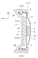
図1に示されるように、車両用シート10は、着座乗員Pの臀部及び大腿部を支持するシートクッション12を備えている。このシートクッション12は、従来周知のスライド機構(図示省略)を介して車両の車体フロア(図示省略)に連結されている。また、車両用シート10は、着座乗員Pの背部を支持するシートバック14を備えている。シートバック14は、下端部がリクライニング機構16を介してシートクッション12の後端部に連結されている。さらに、シートバック14の上端部には、着座乗員Pの頭部を支えるヘッドレスト18が設けられている。
As shown in FIG. 1, the
図1〜図3に示されるように、上記のシートバック14は、シートバックフレーム20と、格子状ばね体25と、シートバックパッド26(図3以外では図示省略)と、荷重伝達部としての衝撃吸収部材28とを備えている。以下、シートバック14の各構成要素について詳細に説明する。
As shown in FIG. 1 to FIG. 3, the seat back 14 includes a seat back
(シートバックフレーム20の構成)
シートバックフレーム20は、シートバック14の骨格を構成するものであり、樹脂(例えば、炭素繊維入り強化プラスチック)により、全体として所謂シェル状に形成されている。このシートバックフレーム20は、シートバックフレーム20の外周部を構成する枠フレーム部20Aと、枠フレーム部20Aの後端側(背面側)に配置された背面パネル部20Bと、を含んで構成されており、枠フレーム部20Aと背面パネル部20Bとが一体に形成されている。
(Configuration of the seat back frame 20)
The seat back
枠フレーム部20Aは、正面視でシート下方側へ開放された略逆U字形状に形成されている。この枠フレーム部20Aは、シートバックフレーム20のシート幅方向両側部分を構成する左右一対のサイドフレーム部22と、シートバックフレーム20の上部を構成するアッパフレーム部24と、を含んで構成されている。左右のサイドフレーム部22は、略板状に形成されて、板厚方向をシート幅方向にしてシート上下方向に延在している。左右のサイドフレーム部22の下端部には、リクライニング機構16を介してシートクッション12の骨格部材であるシートクッションフレーム(図示省略)の後端部が連結されている。
The
アッパフレーム部24は、シート幅方向に延びており、左右のサイドフレーム部22の上端部を連結している。また、アッパフレーム部24には、一対の支持部27が形成されている。これらの支持部27は軸方向をシート上下方向にした略矩形筒状に形成されている。これらの支持部27内には、それぞれヘッドレストサポート29が取り付けられている。これらのヘッドレストサポート29には、ヘッドレスト18の骨格部材であるヘッドレストフレーム30が装着されている。これにより、ヘッドレスト18がシートバックフレーム20の上端部に連結されている。
The
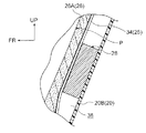
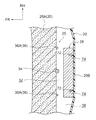
背面パネル部20Bは、略板状に形成されており、板厚方向をシート前後方向にしてシートバック14の背面に配置されている。この背面パネル部20Bは、枠フレーム部20Aと一体に成形されたものであり、外周部が枠フレーム部20Aの後端部に一体に結合されている。この背面パネル部20Bは、図3に示されるように、シート幅方向中央側がシート幅方向両端側よりもシート後方側へ膨出している。この背面パネル部20Bのシート前方側には、格子状ばね体25が配置されている。
The
(格子状ばね体25の構成)
格子状ばね体25は、シートバック14の両側部に位置する左右一対のサイドワイヤ32と、シートバック14のシート幅方向中央部に位置するセンターコード34と、左右のサイドワイヤ32間にわたって設けられた複数本の横張ワイヤ36とによって構成されている。左右のサイドワイヤ32とセンターコード34は、上下方向に延びており、複数本の横張ワイヤ36は、シートバック幅方向に延びている。この格子状ばね体25は、図1〜図3に示されるように、シートバックフレーム20の内側に配置されている。この格子状ばね体25と背面パネル部20Bとの間には、空間38が形成されている。なお、図1及び図4では、格子状ばね体25及び後述する接続ワイヤ40、42を概略的に記載している。また、図3では、図面を見易くする関係から、サイドワイヤ32、センターコード34及び横張ワイヤ36の断面のハッチングを省略している。
(Configuration of lattice-like spring body 25)
The lattice-
各横張ワイヤ36は、左右のサイドワイヤ32よりも線形の小さいばね鋼線によって構成されており、格子状ばね体25の上下方向に間隔を存して配置されている。各横張ワイヤ36の両端部は、左右のサイドワイヤ32に固定されている。これら横張ワイヤ36には、センターコード34を境とする左右対称位置に、上方側へ凸の形状をなす成形部36Aが設けられている。これらの成形部36Aは同一平面内に形成されているため、格子状ばね体25は、概ね平面をなすマット状をなしている。この成形部36AがS形あるいはZ形であってもよいし、横張ワイヤ36がストレートな形状であってもよい。
Each of the
左右のサイドワイヤ32の上端部は、それぞれシート後方側かつシート下方側へ向けて逆U字状に折り曲げられており、シートバックフレーム20の上部に取り付けられたサポートワイヤ37に引っ掛けられている。このサポートワイヤ37は、シート幅方向に直線状に延びている。左右のサイドワイヤ32の下端部は、シートバックフレーム20に支持されておらず、フリーな状態になっている。
The upper ends of the left and
左右のサイドワイヤ32は、上部及び下部がそれぞれ接続ワイヤ40、42を介して左右のサイドフレーム部22に取り付けられている。詳細には、左右のサイドワイヤ32の上部が、左右一対の上部側の接続ワイヤ40を介して左右のサイドフレーム部22に支持されており、左右のサイドワイヤ32の下部が、左右一対の下部側の接続ワイヤ42を介して左右のサイドフレーム部22に支持されている。
The upper and
接続ワイヤ40、42は、左右のサイドワイヤ32よりも径の小さいばね鋼線等の金属線によって形成されている。これらの接続ワイヤ40、42に対応して、左右のサイドフレーム部22に前端部には、上下一対の取付片46、48が設けられている。これらの取付片46、48には、それぞれ取付孔50が形成されており、接続ワイヤ40、42の一端部(前端部)がU字状に折り曲げられて各取付孔50に挿入されている。これにより、接続ワイヤ40、42の前端部が左右のサイドフレーム部22に連結されている。また、接続ワイヤ40、42の他端部(後端部)は、左右のサイドワイヤ32を巻き込むようにして折り曲げられている。これにより、接続ワイヤ40、42の後端部が左右のサイドワイヤ32に連結(係止)されている。
The
これらの接続ワイヤ40、42は、格子状ばね体25に対してシート後方側への荷重が負荷されることにより、引張り荷重を受ける。この引張り荷重が予め設定された値を超えると、各接続ワイヤ40、42は、前端部又は後端部の折り曲げが伸びるように変形する。これにより、各接続ワイヤ40、42と左右のサイドワイヤ32との間、又は各接続ワイヤ40、42と左右のサイドフレーム部22との間の連結状態が解除され、左右のサイドフレーム部22に対する格子状ばね体25の連結状態が解除される。その結果、格子状ばね体25は、上端部のサポートワイヤ37を中心として、シート後方側(背面パネル部20B側)へ変位するようになっている。
These
(シートバックパッド26の構成)
シートバックパッド26は、ウレタンフォーム等の発泡体により形成されたものであり、シートバックフレーム20に対してシート前方側から取り付けられている。このシートバックパッド26の表面は、図示しない表皮材によって覆われている。このシートバックパッド26は、着座乗員Pの腰部及び背部を支持するパッド本体部26Aと、パッド本体部26Aの左右両側部に一体に形成された左右一対のパッドサイド部26Bとによって構成されている。
(Configuration of the seat back pad 26)
The seat back
パッド本体部26Aは、格子状ばね体25の前面に当接した状態で配置されており、格子状ばね体25によってシート後方側から支持されている。左右のパッドサイド部26Bは、シート幅方向内側が開放された開断面形状に形成されており、内側に左右のサイドフレーム部22が嵌り込んでいる。
The pad
(衝撃吸収部材28の構成)
衝撃吸収部材(受圧板)28は、衝撃吸収性を有する材料によって直方体(ブロック状)又は板厚の厚い板状に形成されており、格子状ばね体25と背面パネル部20Bとの間の空間38内に設けられている。この衝撃吸収部材28は、格子状ばね体25の背面におけるシート幅方向中央部で且つシート上下方向中央部よりも若干下方側に位置しており、例えば着座乗員Pの腹部と同等の高さに配置されている。この衝撃吸収部材28は、シート上下方向の寸法及びシート幅方向の寸法に比してシート前後方向の寸法が小さく設定されている。この衝撃吸収部材28の材料としては、例えば、ハニカム構造の構造体、発泡ウレタン、速度依存性物質(東レ株式会社製の衝撃吸収ナイロン等)を用いることができる。
(Configuration of shock absorbing member 28)
The shock absorbing member (pressure receiving plate) 28 is formed in a rectangular parallelepiped (block shape) or a thick plate shape from a material having shock absorbing properties, and a space between the
この衝撃吸収部材28の前面には、格子状ばね体25のセンターコード34と係合するワイヤ係合部としてのフック部28Aが設けられている。このフック部28Aは、シート上下方向から見てシート前方側へ開放された断面略C字形のフック状に形成されており、シート上下方向に延びている。このフック部28Aの内側にセンターコード34が嵌合することにより、衝撃吸収部材28が格子状ばね体25の背面に取り付けられており、格子状ばね体25の背面から衝撃吸収部材28が背面パネル部20B側へ突出している。
A
この衝撃吸収部材28は、例えば、シート上下方向の寸法が、格子状ばね体25のシート上下方向の寸法の4分の1程度に設定されており、シート幅方向の寸法が、格子状ばね体25のシート幅方向の寸法の3分の1程度に設定されている。また、この衝撃吸収部材28は、シート前後方向の寸法が、空間38のシート前後方向の寸法よりも小さく設定されており、衝撃吸収部材28と背面パネル部20Bとの間には、間隙52が形成されている。
The
この衝撃吸収部材28のシート前後方向の寸法は、前述した如く左右のサイドフレーム部22に対する格子状ばね体25の連結状態が解除され、格子状ばね体25が背面パネル部20B側に変位した際に、当該衝撃吸収部材28が格子状ばね体25の下端部と同時又は格子状ばね体25の下端部よりも先に背面パネル部20Bと当接するように設定されている。また、この衝撃吸収部材28のシート前後方向の寸法は、通常時における着座乗員Pからの荷重がシートバックパッド26を介して格子状ばね体25に負荷された状態では、衝撃吸収部材28が背面パネル部20Bと当接しないように設定されている。なお、衝撃吸収部材28におけるシート上下方向の寸法及びシート幅方向の寸法は上記に限らず、適宜変更可能である。
The dimension of the
次に、本実施形態の作用及び効果について説明する。 Next, the operation and effect of this embodiment will be described.
上記構成の車両用シート10では、シートバック14の骨格を構成する樹脂製のシートバックフレーム20が、枠フレーム部20Aと、シートバック14の背面に配置された背面パネル部20Bとを一体に有している。この背面パネル部20Bが設けられることにより、樹脂製のシートバックフレーム20の剛性を効率的に確保することができる。
In the
また、上記のシートバックフレーム20には、ワイヤによって格子状に形成された格子状ばね体25が取り付けられており、当該格子状ばね体25によってシートバックパッド26がシート後方側から支持されている。この格子状ばね体25と背面パネル部20Bとの間には空間38が形成されており、当該空間38内には、衝撃吸収部材28が設けられている。この衝撃吸収部材28は、格子状ばね体25の背面に取り付けられており、背面パネル部20B側へ突出しているが、背面パネル部20Bとの間に間隙52が形成されている。この間隙52によって、格子状ばね体25及びシートバックパッド26のシート後方側への弾性変形を許容することができる。これにより、通常時における着座乗員Pの快適性を確保することができる。
In addition, a lattice-
一方、後面衝突時には、シート後方側へ慣性移動する着座乗員Pからの過大な荷重がシートバックパッド26を介して格子状ばね体25に入力される。これにより、接続ワイヤ40、42が変形し、シートバックフレーム20の左右のサイドフレーム部22に対する格子状ばね体25の連結状態が解除される。その結果、格子状ばね体25がシート後方側へ変位し、格子状ばね体25と背面パネル部20Bとが相対的に接近する。これにより、着座乗員Pの背部及び腰部をシートバック14内に入り込ませることができるので、着座乗員Pの頭部をヘッドレスト18によって速やかに支持することが可能になる。
On the other hand, at the time of a rear collision, an excessive load from the seated occupant P that moves inertially toward the rear of the seat is input to the
しかも、図4に示されるように、上記の接近によって衝撃吸収部材28が格子状ばね体25と背面パネル部20Bとの間に挟まれると、着座乗員Pからの荷重が背面パネル部20Bに伝達される。これにより、シートバックフレーム20の背面パネル部20Bによって着座乗員Pの背部及び腰部を良好に支持することができる。以上のことから、後面衝突時における乗員保護性能の向上に寄与する。なお、図5においては、説明の都合上、着座乗員Pからの荷重を伝達することが好ましい背面パネル部20Bの領域にハッチングを付与している。
Moreover, as shown in FIG. 4, when the
また、上記の衝撃吸収部材28は、衝撃吸収性を有する材料によって形成されている。このため、後面衝突時に格子状ばね体25と背面パネル部20Bとの間に挟まれた衝撃吸収部材28(図6A参照)が、図6Bに示される如く着座乗員Pからの過大な荷重を受けてシート前後方向に潰される(圧縮変形される)ことにより、衝撃を吸収することができる。これにより、後面衝突時における乗員保護性能の向上に一層寄与する。また、この衝撃吸収部材28の材料として、前述したような速度依存性物質を使用した場合には、シートバック14内への着座乗員Pの背部及び腰部の入り込みが、衝撃吸収部材28によって制限されることを抑制できるので、着座乗員Pの頭部を速やかにヘッドレスト18に支持させる効果に寄与する。
The
なお、図7に示される比較例60のように、衝撃吸収部材28を備えていない構成では、格子状ばね体25が着座乗員Pからの過大な荷重によってシート後方側へ変位した際に、格子状ばね体25の下端のみが背面パネル部20Bと当接し、着座乗員Pからの荷重が背面パネル部20Bに十分に伝達されなくなる。その結果、着座乗員Pの背部及び腰部の支持が不十分になることが考えられるが、本実施形態ではこれを回避することができる。
Note that, in the configuration in which the
さらに、本実施形態では、衝撃吸収部材28は、前記格子状ばね体25を構成するワイヤの一つであるセンターコード34に係合するフック部28Aを有している。このため、車両用シート10の製造時においては、衝撃吸収部材28に設けられたワイヤ係合部を、センターコード34に係合させることにより、衝撃吸収部材28を容易に格子状ばね体25に取り付けることができる。
Further, in the present embodiment, the
次に、本発明の他の実施形態について説明する。なお、前記第1実施形態と基本的に同様の構成及び作用については、前記第1実施形態と同符号を付与しその説明を省略する。 Next, another embodiment of the present invention will be described. In addition, about the structure and effect | action similar to the said 1st Embodiment, the same code | symbol as the said 1st Embodiment is provided, and the description is abbreviate | omitted.
<第2の実施形態>
図8には、本発明の第2実施形態に係る車両用シート70の主要部の構成が側方から見て部分断面図にて示されている。また、図9には、図8のF9−F9線に沿った切断面が断面図にて示されている。この実施形態では、衝撃吸収部材28が背面パネル部20Bに取り付けられており、前記第1実施形態に係るワイヤ爪部72が省略されている。それ以外の構成は前記第1実施形態と同様である。
<Second Embodiment>
FIG. 8 is a partial cross-sectional view of the configuration of the main part of the
図9に示されるように、背面パネル部20Bの前面におけるシート幅方向中央部には、係合部としての左右一対の爪部72が設けられている。これらの爪部72は、背面パネル部20Bの前面からシート前方側へ突出しており、シート上下方向に延在している。これらの爪部72は、前端側がシート幅方向外側へ向けて屈曲しており、シート上下方向から見た断面形状が略L字状に形成されている。
As shown in FIG. 9, a pair of left and
また、衝撃吸収部材28には、背面パネル部20B側の面に、被係合部としての左右一対の係合溝74が設けられている。これらの係合溝74は、衝撃吸収部材28の上端から下端まで延びており、シート上下方向から見た断面形状が一対の爪部72に対応した断面L字状に形成されている。これらの係合溝74に一対の爪部72が係合(ここでは嵌合)することにより、衝撃吸収部材28が背面パネル部20Bの前面に取り付けられている。
Further, the
この実施形態においても、前記第1実施形態と同様に、通常時における着座乗員の快適性を確保しつつ、後面衝突時における乗員保護性能の向上に寄与する。また、車両用シート70の製造時においては、背面パネル部20Bに設けられた一対の爪部72を、衝撃吸収部材28に設けられた一対の係合溝74に係合させることにより、衝撃吸収部材28を容易に背面パネル部20Bに取り付けることができる。
In this embodiment as well, as in the first embodiment, the comfort of the seated occupant at the normal time is ensured and the occupant protection performance at the time of the rear collision is improved. Further, at the time of manufacturing the
<第3の実施形態>
図10には、本発明の第3実施形態に係る車両用シート80の主要部の構成が側方から見て部分断面図にて示されている。また、図11には、図10のF11−F11線に沿った切断面が断面図にて示されている。この実施形態では、前記第1実施形態に係る衝撃吸収部材28が省略されている。その代わりに、背面パネル部20Bには、荷重伝達部としての複数(ここでは3つ)のリブ82が設けられている。これらのリブ82は、背面パネル部20Bが部分的にシート前方側へ膨出することにより形成されたものであり、背面パネル部20Bの中央部においてシート上下方向に延びると共に、シート幅方向に並んでいる。これらのリブ82は、背面パネル部20Bの前面から格子状ばね体25側へ突出しているが、これらのリブ82と格子状ばね体25との間には間隙52が形成されている。
<Third Embodiment>
FIG. 10 is a partial cross-sectional view showing the configuration of the main part of the
この実施形態では、前記第1実施形態のように、衝撃吸収部材28の変形による衝撃吸収性を得ることができないが、それ以外の点では、前記第1実施形態と基本的に同様の作用効果を得ることができる。また、この実施形態では、荷重伝達部である複数のリブ82を、シートバックフレーム20の成形時に背面パネル部20Bに一体に成形することができる。
In this embodiment, unlike the first embodiment, it is not possible to obtain shock absorption due to the deformation of the
<第4の実施形態>
図12には、本発明の第4実施形態に係る車両用シート90の主要部の構成が側方から見て部分断面図にて示されている。また、図13には、図12のF13−F13線に沿った切断面が断面図にて示されている。この実施形態では、前記第1実施形態に係る衝撃吸収部材28が省略されている。その代わりに、背面パネル部20Bの前面には、荷重伝達部としてのリブ92が接合されている。このリブ92は、樹脂によって浅底な各皿状に形成されており、開口部を背面パネル部20B側へ向けて配置されている。このリブ92の開口縁部は、接着や溶着等の手段によって背面パネル部20Bの前面に接合されている。このリブ92は、背面パネル部20Bの前面から格子状ばね体25側へ突出しているが、このリブ92と格子状ばね体25との間には間隙52が形成されている。
<Fourth Embodiment>
FIG. 12 shows a partial cross-sectional view of the configuration of the main part of the
この実施形態では、前記第1実施形態のように、衝撃吸収部材28の変形による衝撃吸収性を得ることができないが、それ以外の点では、前記第1実施形態と基本的に同様の作用効果を得ることができる。また、この実施形態では、荷重伝達部であるリブ92が、背面パネル部20Bに接合されるので、リブ92によってシートバックフレーム20の成形性が低下しないようにすることができる。また、車種等に応じてリブ92のみを変更することで、シートバックフレーム20の汎用性を向上させることができる。
In this embodiment, unlike the first embodiment, it is not possible to obtain shock absorption due to the deformation of the
<第5の実施形態>
図14には、本発明の第5実施形態に係る車両用シート100が備えるシートバックフレーム20、格子状ばね体25及び衝撃吸収部材102を含む周辺部材の構成が斜視図にて示されている。また、図15には、同車両用シート100における衝撃吸収部材102の周辺の構成がシート前方側から見た正面図にて示されており、図16には、図15のF16−F16線に沿った切断面に対応した断面図が示されている。この実施形態では、衝撃吸収部材102の構成が、前記第1実施形態に係る衝撃吸収部材28とは異なっている。それ以外の構成は、前記第1実施形態と同様である。
<Fifth Embodiment>
FIG. 14 is a perspective view showing a configuration of peripheral members including the seat back
衝撃吸収部材102は、シートバックフレーム20よりも軟質の樹脂により形成されたものであり、背面パネル部20Bの前面における下部側に取り付けられている。この衝撃吸収部材102は、背面パネル部20Bに沿った方向であるシート幅方向に並ぶ複数(ここでは3つの)の湾曲部102A、102B、102Cを有している。これらの湾曲部102A、102B、102Cは、シート上下方向から見てシート前方側へ凸をなすように円弧状に湾曲している。シート幅方向両端側に位置する湾曲部102A、102Cと、シート幅方向中央部に位置する湾曲部102Bは、それぞれ平板状の低強度接合部102Dを介して一体に接続されている。また、シート幅方向両端側に位置する湾曲部102A、102Cにおける湾曲部102Bとは反対側には、それぞれ平板状の高強度接合部102Eが一体に設けられている。
The
各低強度接合部102Dは、シート上下方向に並ぶ複数(ここでは3つ)の打点Wにおいて背面パネル部20Bの前面に溶着(接合)されており、各高強度接合部102Eは、シート上下方向に並ぶ複数(ここでは5つ)の打点Wにおいて背面パネル部20Bの前面に溶着(接合)されている。このため、低強度接合部102Dは、高強度接合部102Eよりも背面パネル部20Bとの接合強度が低く設定されている。そして、シート幅方向両端側に位置する湾曲部102A、102Cは、湾曲方向一端部(シート幅方向外側端部)が、高強度接合部102Eによって支持される一方、湾曲方向他端部(シート幅方向内側端部)が、低強度接合部102Dによって支持されている。また、シート幅方向中央部に位置する湾曲部102Bは、湾曲方向両端部(シート幅方向両端部)が、それぞれ低強度接合部102Dによって支持されている。つまり、この衝撃吸収部材102では、湾曲部102A、102B、102Cの湾曲方向両端部のうちの少なくとも一方が低強度接合部102Dによって支持されている。
Each low-strength
これらの湾曲部102A、102B、102Cは、背面パネル部20Bからシート前方側へ突出しているが、これらの湾曲部102A、102B、102Cと格子状ばね体25と間には、それぞれ間隙52が形成されている(図16参照)。これらの間隙52によって、格子状ばね体25及びシートバックパッド26のシート後方側への弾性変形を許容することができるので、通常時における着座乗員Pの快適性を確保することができる。なお、図16、図17A、図17Bでは、格子状ばね体25を概略的に記載している。
These
一方、後面衝突時には、シート後方側へ慣性移動する着座乗員Pからの過大な荷重がシートバックパッド26に入力されることにより、格子状ばね体25に入力されることにより、格子状ばね体25と背面パネル部20Bとが相対的に接近する。これにより、着座乗員Pの背部及び腰部をシートバック14内に入り込ませることができるので、着座乗員Pの頭部をヘッドレスト18によって速やかに支持することが可能になる。
On the other hand, at the time of a rear collision, an excessive load from the seated occupant P that moves inertially toward the rear of the seat is input to the seat back
しかも、図17Aに示されるように、上記の接近によって衝撃吸収部材102の一又は複数の湾曲部102A、102B、102Cが格子状ばね体25と背面パネル部20Bとの間に挟まれると、着座乗員Pからの荷重が背面パネル部20Bに伝達される。これにより、シートバックフレーム20の背面パネル部20Bによって着座乗員Pの背部及び腰部が支持される。
In addition, as shown in FIG. 17A, when one or more of the
そして、衝撃吸収部材102に加わる荷重が一定以上に増加すると、衝撃吸収部材102の低強度接合部102Dと背面パネル部20Bとの接合が破断し、湾曲部102A、102B、102Cの湾曲方向両端部のうちの少なくとも一方が低強度接合部102Dによる支持を解除される。これにより、図17Bに示されるように、湾曲部102A、102B、102Cが平坦状に潰されて衝撃が吸収されると共に、着座乗員Pの背部及び腰部が更にシートバック内に入り込み、着座乗員Pから背面パネル部20Bに伝達される荷重が増加する。その結果、背面パネル部20Bによる着座乗員Pの背部及び腰部の支持力を増加させることができる。以上のことから、後面衝突時における乗員保護性能の向上に寄与する。
When the load applied to the
しかも、この実施形態では、低強度接合部102Dは、高強度接合部102Eよりも少ない打点において背面パネル部20Bと溶着されている。これにより、低強度接合部102D及び高強度接合部102Eの接合強度を容易に異ならせることができる。なお、低強度接合部102D及び高強度接合部102Eと背面パネル部20Bとの接合は、溶着に限らず、接着等の手段を用いてもよい。
Moreover, in this embodiment, the low-strength
また、上記第5実施形態において、図18に示される車両用シート100’のように、格子状ばね体25が省略された構成にしてもよい。その場合、通常時には、衝撃吸収部材102の湾曲部102A、102B、102Cによってシートバックパッド26をシート後方側から弾性的に支持することにより、着座乗員Pの快適性を確保することができる。しかも、格子状ばね体25が省略されることにより、低コスト化を図ることができる。
Moreover, in the said 5th Embodiment, you may make it the structure by which the grid | lattice-
<第6の実施形態>
図19には、本発明の第6実施形態に係る車両用シート110の主要部の構成が側方から見た部分断面図にて示されている。また、図20には、図19のF20−F20線に沿った切断面が断面図にて示されている。この実施形態では、前記第1実施形態に係る衝撃吸収部材28が省略されており、背面パネル部20Bの前面側には、別の衝撃吸収部材(荷重伝達部)112が設けられている。この衝撃吸収部材112は、板状に形成された板状部材114と、弾性部材としての複数(ここでは6つ)の圧縮コイルスプリング116とを備えている。
<Sixth Embodiment>
FIG. 19 shows a partial cross-sectional view of a configuration of a main part of a
板状部材114は、板厚方向がシート前後方向に沿う姿勢で背面パネル部20Bの中央部よりも若干下方側に配置されており、シート前後方向から見て矩形状に形成されている。この板状部材114は、所謂嵌め殺しによって背面パネル部20Bの前面に取り付けられている。つまり、板状部材114のシート幅方向両端部には、それぞれシート後方側かつシート幅方向外側へ突出した引掛部114Aが設けられている。これらの引掛部114Aは、シート上下方向から見てシート前方側が開放された略V字状をなしている。これらの引掛部114Aに対応して背面パネル部20Bには、左右一対の爪部118が設けられている。これらの爪部118は、シート前方側へ突出しており、先端側がシート幅方向中央側へ向けて屈曲している。これらの爪部118の間には、板状部材114が嵌め込まれており、左右の引掛部114Aが左右の爪部118に引っ掛かることにより、板状部材114が背面パネル部20Bに保持されている。この板状部材114と格子状ばね体25との間には、間隙52が形成されている。
The plate-
板状部材114と背面パネル部20Bとの間には、隙間120が形成されており、当該隙間120には、6つの圧縮コイルスプリング116が配置されている。これらの圧縮コイルスプリング116は、軸線方向がシート前後方向に沿っており、左右に2列で上下に3列になるように配置されている。これらの圧縮コイルスプリング116は、板状部材114と背面パネル部20Bとの間に挟まれている。なお、圧縮コイルスプリング116の代わりに、ゴム等からなる弾性部材を用いてもよい。
A
この実施形態では、後面衝突時における格子状ばね体25と背面パネル部20Bとの相対的な接近により、格子状ばね体25が板状部材114を介して複数の圧縮コイルスプリング116をシート後方側へ押圧すると、板状部材114と背面パネル部20Bとの間で複数の圧縮コイルスプリング116が圧縮変形される。これにより、衝撃が吸収される。このように、格子状ばね体25が板状部材114を介して複数の圧縮コイルスプリング116を押圧するため、複数の圧縮コイルスプリング116からの反力が格子状ばね体25に対して均一に加わるようにすることができる。
In this embodiment, due to the relative approach between the lattice-
(実施形態の補足説明)
前記各実施形態では、格子状ばね体25が接続ワイヤ40、42を介してシートバックフレーム20の左右のサイドフレーム部22に接続(連結)された構成にしたが、本発明はこれに限るものではない。例えば、格子状ばね体25の横張ワイヤ36等から一体に延出された接続部(連結部)によって、格子状ばね体25が左右のサイドフレーム部22に直接連結された構成にしてもよい。
(Supplementary explanation of the embodiment)
In each of the above embodiments, the lattice-
また、前記各実施形態では、後面衝突時に接続ワイヤ40、42が変形することにより、格子状ばね体25とシートバックフレーム20の左右のサイドフレーム部22との連結状態が解除される構成にしたが、本発明はこれに限るものではなく、格子状ばね体25と左右のサイドフレーム部22との連結状態が解除されない構成にしてもよい。例えば、後面衝突時に格子状ばね体が背面パネル部側へ弾性変形することにより、荷重伝達部が格子状ばね体と背面パネル部との間に挟まれる構成にしてもよい。また例えば、格子状ばね体と左右のサイドフレーム部との接続部(連結部)が変形して伸びることにより、格子状ばね体とシートフレームとの連結状態が維持されたまま、荷重伝達部が格子状ばね体と背面パネル部との間に挟まれる構成にしてもよい。
Moreover, in each said embodiment, it was set as the structure which the connection state of the grid | lattice-
その他、本発明は、その要旨を逸脱しない範囲で種々変更して実施できる。また、本発明の権利範囲が前記各実施形態に限定されないことは勿論である。 In addition, the present invention can be implemented with various modifications without departing from the scope of the invention. It goes without saying that the scope of rights of the present invention is not limited to the above embodiments.
10 車両用シート
14 シートバック
18 ヘッドレスト
20 シートバックフレーム
20B 背面パネル部
25 格子状ばね体
26 シートバックパッド
28 衝撃吸収部材(荷重伝達部)
28A フック部(ワイヤ係合部)
38 空間
52 間隙
72 爪部(係合部)
74 係合溝(被係合部)
80 車両用シート
82 リブ(荷重伝達部)
90 車両用シート
92 リブ(荷重伝達部)
100 車両用シート
102 衝撃吸収部材(荷重伝達部)
102A、102B、102C 湾曲部
102D 低強度接合部
102E 高強度接合部
110 車両用シート
112 衝撃吸収部材(荷重伝達部)
114 板状部材
116 圧縮コイルスプリング(弾性部材)
120 隙間
DESCRIPTION OF
28A hook part (wire engaging part)
38
74 Engagement groove (engaged part)
80
90
100
102A, 102B, 102C
114
120 gap
Claims (10)
前記シートバックの上端部に設けられたヘッドレストと、
前記シートバックフレームの前面側に設けられたシートバックパッドと、
ワイヤにより格子状に形成され、前記背面パネル部のシート前方側で前記シートバックフレームに取り付けられ、前記シートバックパッドをシート後方側から弾性的に支持すると共に、前記背面パネル部との間に空間が形成された格子状ばね体と、
前記格子状ばね体及び前記背面パネル部のうちの一方に設けられて前記空間内に配置され、他方の側へ突出すると共に、他方との間に間隙が形成された荷重伝達部と、
を備えた車両用シート。 A frame frame portion that forms a skeleton of the seat back formed of resin, and that forms an outer periphery of the skeleton includes a pair of left and right side frames that form both sides of the skeleton in the seat width direction, and an upper portion of the skeleton. A plate-like rear panel portion formed integrally with the frame frame portion is integrally coupled to the left and right side frames and the upper frame to form a back surface of the seat back. and placed seat back frame,
A headrest provided at the upper end of the seat back;
A seat back pad provided on the front side of the seat back frame;
It is formed in a lattice shape with wires, is attached to the seat back frame on the seat front side of the back panel portion, elastically supports the seat back pad from the seat rear side, and has a space between the back panel portion and the back panel portion. A lattice-like spring body formed with
A load transmitting portion provided in one of the lattice-like spring body and the back panel portion, disposed in the space, protruding to the other side, and having a gap formed between the other;
Vehicle seat equipped with
前記シートバックの上端部に設けられたヘッドレストと、
前記シートバックフレームの前面側に設けられ、前記背面パネル部との間に空間が形成されたシートバックパッドと、
前記シートバックフレームよりも軟質の樹脂により形成されて前記空間内に配置され、高強度接合部及び該高強度接合部よりも接合強度が低い低強度接合部において前記背面パネル部に接合されると共に、シート前方側へ凸をなすように湾曲した一又は複数の湾曲部を有し、当該湾曲部の湾曲方向両端部のうちの少なくとも一方が前記低強度接合部によって支持された衝撃吸収部材と、
を備えた車両用シート。 A seat back frame that is formed of resin and constitutes a skeleton of the seat back, and has a plate-like back panel portion disposed on the back surface of the seat back;
A headrest provided at the upper end of the seat back;
A seat back pad provided on the front side of the seat back frame and having a space formed between the back panel portion;
It is formed of a softer resin than the seat back frame and is disposed in the space, and is joined to the back panel portion at a high strength joint portion and a low strength joint portion whose joint strength is lower than the high strength joint portion. An impact absorbing member having one or a plurality of curved portions curved so as to protrude toward the front side of the seat, and at least one of both ends in the bending direction of the curved portion supported by the low-strength joint portion;
Vehicle seat equipped with
Priority Applications (4)
| Application Number | Priority Date | Filing Date | Title |
|---|---|---|---|
| JP2014129583A JP6294772B2 (en) | 2014-06-24 | 2014-06-24 | Vehicle seat |
| CN201510333973.1A CN105270231B (en) | 2014-06-24 | 2015-06-16 | Vehicle seat |
| US14/741,325 US9610871B2 (en) | 2014-06-24 | 2015-06-16 | Vehicle seat |
| EP15173302.9A EP2960107A1 (en) | 2014-06-24 | 2015-06-23 | Vehicle seat |
Applications Claiming Priority (1)
| Application Number | Priority Date | Filing Date | Title |
|---|---|---|---|
| JP2014129583A JP6294772B2 (en) | 2014-06-24 | 2014-06-24 | Vehicle seat |
Publications (2)
| Publication Number | Publication Date |
|---|---|
| JP2016007936A JP2016007936A (en) | 2016-01-18 |
| JP6294772B2 true JP6294772B2 (en) | 2018-03-14 |
Family
ID=53487239
Family Applications (1)
| Application Number | Title | Priority Date | Filing Date |
|---|---|---|---|
| JP2014129583A Active JP6294772B2 (en) | 2014-06-24 | 2014-06-24 | Vehicle seat |
Country Status (4)
| Country | Link |
|---|---|
| US (1) | US9610871B2 (en) |
| EP (1) | EP2960107A1 (en) |
| JP (1) | JP6294772B2 (en) |
| CN (1) | CN105270231B (en) |
Families Citing this family (17)
| Publication number | Priority date | Publication date | Assignee | Title |
|---|---|---|---|---|
| US9738194B2 (en) * | 2013-04-08 | 2017-08-22 | Ts Tech Co., Ltd. | Vehicle seat and seat frame for same |
| JP2016013824A (en) * | 2014-07-03 | 2016-01-28 | 日本発條株式会社 | Vehicle seat |
| JP6583106B2 (en) * | 2016-04-08 | 2019-10-02 | トヨタ紡織株式会社 | Vehicle seat |
| JP6614003B2 (en) * | 2016-04-15 | 2019-12-04 | トヨタ紡織株式会社 | Vehicle seat |
| JP6812902B2 (en) * | 2017-05-23 | 2021-01-13 | トヨタ紡織株式会社 | Vehicle seat |
| DE102017220077A1 (en) | 2017-11-10 | 2019-05-16 | Lear Corporation | Carrying device for a vehicle seat assembly |
| JP6649934B2 (en) * | 2017-12-11 | 2020-02-19 | 本田技研工業株式会社 | Seats and vehicles |
| DE102018202032A1 (en) | 2018-02-09 | 2019-08-14 | Lear Corporation | SHOCK ABSORPTION FOR A REAR OCCUPANT |
| JP7099210B2 (en) * | 2018-09-12 | 2022-07-12 | トヨタ自動車株式会社 | Rearward occupant protection device |
| FR3092044B1 (en) | 2019-01-25 | 2021-02-12 | Faurecia Sieges Dautomobile | Seat element rear panel |
| US10737600B1 (en) * | 2019-02-01 | 2020-08-11 | Ford Global Technologies, Llc | EPP seat back carrier |
| CN212422911U (en) * | 2019-03-01 | 2021-01-29 | 丰田纺织株式会社 | Vehicle seat and load absorbing member for vehicle seat |
| US11117537B2 (en) * | 2019-03-19 | 2021-09-14 | Faurecia Automotive Seating, Llc | Backrest of a vehicle seat |
| CN111791771B (en) * | 2019-04-09 | 2023-04-28 | 南京同宁新材料研究院有限公司 | Adjustable automobile seat backrest and adjusting method thereof |
| JP7370727B2 (en) * | 2019-04-25 | 2023-10-30 | トヨタ紡織株式会社 | seat back |
| US11603019B2 (en) * | 2019-06-17 | 2023-03-14 | Zoox, Inc. | Seat crush structure |
| FR3106574B1 (en) * | 2020-01-28 | 2024-02-16 | Safran Seats | SEAT ELEMENT WITH A BOX STRUCTURE |
Family Cites Families (27)
| Publication number | Priority date | Publication date | Assignee | Title |
|---|---|---|---|---|
| JPS6225226U (en) * | 1985-07-30 | 1987-02-16 | ||
| JP3148336B2 (en) * | 1991-12-26 | 2001-03-19 | トヨタ自動車株式会社 | Front seat cushion structure |
| US5558398A (en) * | 1993-11-08 | 1996-09-24 | Santos; James P. | Self-adjusting seating system |
| US5509716A (en) * | 1994-11-08 | 1996-04-23 | General Motors Corporation | Vehicle seat with perimeter frame and pelvic catcher |
| JP3493927B2 (en) * | 1996-12-20 | 2004-02-03 | トヨタ自動車株式会社 | Vehicle seat |
| US5769489A (en) * | 1997-05-09 | 1998-06-23 | Dellanno; Ronald P. | Energy absorbing support for vehicular passengers |
| US6062642A (en) * | 1998-04-02 | 2000-05-16 | Volkswagen Ag | Vehicle seat |
| DE19905215C2 (en) * | 1999-02-09 | 2002-01-31 | Wolfgang Lortz | Seat |
| DE10031232A1 (en) * | 2000-06-27 | 2002-01-31 | Wolfgang Stelzenmueller | safety seat |
| JP3906340B2 (en) * | 2001-08-13 | 2007-04-18 | スズキ株式会社 | Headrest structure |
| TW535749U (en) * | 2001-12-19 | 2003-06-01 | Bo-De Chen | Safety seat |
| JP2004016708A (en) * | 2002-06-20 | 2004-01-22 | Shigeru Co Ltd | Seat back for vehicles |
| JP4850476B2 (en) * | 2005-10-18 | 2012-01-11 | デルタ工業株式会社 | Vehicle seat |
| JP5452858B2 (en) * | 2007-10-31 | 2014-03-26 | 富士重工業株式会社 | Vehicle seat |
| KR101013904B1 (en) * | 2007-12-18 | 2011-02-14 | 기아자동차주식회사 | Frame Structure For A Seatback of Vehicles |
| JP5365167B2 (en) * | 2008-11-28 | 2013-12-11 | トヨタ紡織株式会社 | Vehicle seat cushion |
| FR2946586B1 (en) * | 2009-06-16 | 2013-02-08 | Faurecia Sieges Automobile | SEAT BACKREST FOR VEHICLE. |
| US8267471B2 (en) * | 2009-08-24 | 2012-09-18 | Honda Motor Co., Ltd. | Passive energy absorbing seat |
| US8172320B2 (en) * | 2010-02-11 | 2012-05-08 | Nissan North America, Inc. | Impact absorption block for vehicle seatback assembly |
| JP5054155B2 (en) * | 2010-06-04 | 2012-10-24 | 本田技研工業株式会社 | Seat back frame |
| US8955907B2 (en) * | 2010-12-24 | 2015-02-17 | Ts Tech Co., Ltd. | Vehicle seat |
| KR101343476B1 (en) * | 2011-06-16 | 2013-12-19 | 도요타 지도샤(주) | Seat backboard and vehicle seat |
| DE102011117038A1 (en) * | 2011-10-27 | 2013-05-02 | GM Global Technology Operations LLC | Vehicle seat for a motor vehicle |
| WO2013094666A1 (en) * | 2011-12-21 | 2013-06-27 | 株式会社東洋シート | Vehicle seat back |
| JP6017816B2 (en) * | 2012-03-30 | 2016-11-02 | テイ・エス テック株式会社 | Seat with air bag module |
| US9126504B2 (en) * | 2013-01-24 | 2015-09-08 | Ford Global Technologies, Llc | Integrated thin flex composite headrest assembly |
| EP3137338A4 (en) * | 2014-05-02 | 2017-12-27 | Reliant Worldwide Plastics, LLC | Method and system for homogenous thermoplastic seat back assembly |
-
2014
- 2014-06-24 JP JP2014129583A patent/JP6294772B2/en active Active
-
2015
- 2015-06-16 US US14/741,325 patent/US9610871B2/en active Active
- 2015-06-16 CN CN201510333973.1A patent/CN105270231B/en active Active
- 2015-06-23 EP EP15173302.9A patent/EP2960107A1/en not_active Withdrawn
Also Published As
| Publication number | Publication date |
|---|---|
| CN105270231B (en) | 2019-03-12 |
| CN105270231A (en) | 2016-01-27 |
| EP2960107A1 (en) | 2015-12-30 |
| JP2016007936A (en) | 2016-01-18 |
| US9610871B2 (en) | 2017-04-04 |
| US20150367762A1 (en) | 2015-12-24 |
Similar Documents
| Publication | Publication Date | Title |
|---|---|---|
| JP6294772B2 (en) | Vehicle seat | |
| JP5452858B2 (en) | Vehicle seat | |
| US9586508B2 (en) | Vehicle seat | |
| US10442332B2 (en) | Seat backrest and seat including the same | |
| US8714641B2 (en) | Vehicle seat | |
| US20120126591A1 (en) | Energy management load limiting vehicle seat member | |
| JP4728670B2 (en) | Automotive seat backrest frame | |
| WO2013133245A1 (en) | Vehicle seat | |
| JP5708302B2 (en) | Resin seat back spring and vehicle seat | |
| WO2010122998A1 (en) | Passenger protection device for vehicle | |
| JP6130201B2 (en) | Vehicle seat | |
| JP5956202B2 (en) | Vehicle seat | |
| WO2013133246A1 (en) | Vehicle seat | |
| JP7239801B2 (en) | vehicle seat | |
| JP2012171610A (en) | Seat for automobile | |
| CN112092701B (en) | Head rest | |
| JP5424398B2 (en) | Seat structure | |
| JP5575304B2 (en) | Vehicle seat | |
| JP2013189108A (en) | Vehicle seat | |
| JP6361474B2 (en) | Vehicle seat back | |
| CN116923212A (en) | Seat for vehicle | |
| JP2015157555A (en) | Seat for vehicle |
Legal Events
| Date | Code | Title | Description |
|---|---|---|---|
| A621 | Written request for application examination |
Free format text: JAPANESE INTERMEDIATE CODE: A621 Effective date: 20170210 |
|
| A977 | Report on retrieval |
Free format text: JAPANESE INTERMEDIATE CODE: A971007 Effective date: 20171130 |
|
| A131 | Notification of reasons for refusal |
Free format text: JAPANESE INTERMEDIATE CODE: A131 Effective date: 20171205 |
|
| A521 | Request for written amendment filed |
Free format text: JAPANESE INTERMEDIATE CODE: A523 Effective date: 20180111 |
|
| TRDD | Decision of grant or rejection written | ||
| A01 | Written decision to grant a patent or to grant a registration (utility model) |
Free format text: JAPANESE INTERMEDIATE CODE: A01 Effective date: 20180213 |
|
| A61 | First payment of annual fees (during grant procedure) |
Free format text: JAPANESE INTERMEDIATE CODE: A61 Effective date: 20180216 |
|
| R150 | Certificate of patent or registration of utility model |
Ref document number: 6294772 Country of ref document: JP Free format text: JAPANESE INTERMEDIATE CODE: R150 |
|
| R250 | Receipt of annual fees |
Free format text: JAPANESE INTERMEDIATE CODE: R250 |
|
| R250 | Receipt of annual fees |
Free format text: JAPANESE INTERMEDIATE CODE: R250 |
|
| R250 | Receipt of annual fees |
Free format text: JAPANESE INTERMEDIATE CODE: R250 |