JP6531401B2 - Plastic bottle - Google Patents

Plastic bottle Download PDF

Info

Publication number
JP6531401B2
JP6531401B2 JP2015010759A JP2015010759A JP6531401B2 JP 6531401 B2 JP6531401 B2 JP 6531401B2 JP 2015010759 A JP2015010759 A JP 2015010759A JP 2015010759 A JP2015010759 A JP 2015010759A JP 6531401 B2 JP6531401 B2 JP 6531401B2
Authority
JP
Japan
Prior art keywords
plastic bottle
pressure absorbing
pressure
panel
shoulder
Prior art date
Legal status (The legal status is an assumption and is not a legal conclusion. Google has not performed a legal analysis and makes no representation as to the accuracy of the status listed.)
Active
Application number
JP2015010759A
Other languages
Japanese (ja)
Other versions
JP2016132500A (en
Inventor
勇介 須賀
勇介 須賀
琢磨 宮脇
琢磨 宮脇
Current Assignee (The listed assignees may be inaccurate. Google has not performed a legal analysis and makes no representation or warranty as to the accuracy of the list.)
Dai Nippon Printing Co Ltd
Original Assignee
Dai Nippon Printing Co Ltd
Priority date (The priority date is an assumption and is not a legal conclusion. Google has not performed a legal analysis and makes no representation as to the accuracy of the date listed.)
Filing date
Publication date
Application filed by Dai Nippon Printing Co Ltd filed Critical Dai Nippon Printing Co Ltd
Priority to JP2015010759A priority Critical patent/JP6531401B2/en
Publication of JP2016132500A publication Critical patent/JP2016132500A/en
Application granted granted Critical
Publication of JP6531401B2 publication Critical patent/JP6531401B2/en
Active legal-status Critical Current
Anticipated expiration legal-status Critical

Links

Images

Landscapes

  • Containers Having Bodies Formed In One Piece (AREA)

Description

本発明は、プラスチックボトルに関し、より詳細には、自動販売機などによって加温販売されるプラスチックボトルの構造に関する。   The present invention relates to a plastic bottle, and more particularly to the structure of a plastic bottle heated and sold by a vending machine or the like.

例えば、飲料が充填される容器としてプラスチックボトルが用いられる。このようなプラスチックボトルの生産量は年々増加傾向にある。一方で、省資源化、ごみの減量化や、輸送時の環境負荷低減等による、エネルギー使用量、及び二酸化炭素排出量の低減の観点から原料の使用量を削減することによるプラスチックボトルの軽量化が取り組まれている。しかしながら、プラスチックボトルを軽量化すると容器の肉厚が薄くなる為、プラスチックボトルの強度が低下する傾向がある。   For example, a plastic bottle is used as a container filled with a beverage. The production volume of such plastic bottles is increasing year by year. On the other hand, weight reduction of plastic bottles by reducing the amount of raw materials used from the viewpoint of reduction of energy consumption and carbon dioxide emissions by resource saving, waste reduction, environmental load reduction etc. Is being addressed. However, when the weight of the plastic bottle is reduced, the thickness of the container is reduced, so that the strength of the plastic bottle tends to decrease.

プラスチックボトルは、複数本の容器の口が上を向いた状態で段ボール等に箱詰めにされたものを複数個積み上げ一つのパレットとして、保管、及び輸送される。したがって、下段にあるプラスチックボトルは、鉛直方向に加わる荷重によって変形が生じやすくなる傾向があり、外観不良や荷崩れが発生するおそれがある。   The plastic bottles are stored and transported as a single pallet by stacking a plurality of boxes packed in a cardboard or the like with the mouths of the plurality of containers facing upward. Therefore, the plastic bottle in the lower stage tends to be easily deformed due to the load applied in the vertical direction, and there is a possibility that the appearance defect or the load collapse may occur.

また、自動販売機内においては、プラスチックボトルは横向きに積載される。したがって、下段にあるプラスチックボトルは、側面に加わる荷重によって変形が生じ易くなる傾向があり、外観不良や自動販売機から正常に排出されなくなるおそれがある。なお、プラスチックボトルが、自動販売機から正常に排出されるか否かの特性はベンダー適性とも称される。   In addition, in the vending machine, plastic bottles are loaded sideways. Therefore, the plastic bottle in the lower stage tends to be easily deformed due to the load applied to the side surface, and there is a possibility that it may not be properly discharged from the appearance defect or the vending machine. In addition, the characteristic of whether a plastic bottle is normally discharged | emitted from a vending machine is also called vendor aptitude.

ところで、プラスチックボトルは、飲料を加温状態で販売する際の容器としても用いられるようになっている。このような加温用のプラスチックボトルでは、内容物の充填時と保管時とで温度変化が生じるが、この温度変化に応じて内部の圧力が変化する。   By the way, the plastic bottle is also used as a container at the time of selling a drink in a heated state. In such a heating plastic bottle, a temperature change occurs between filling and storage of contents, but the internal pressure changes according to the temperature change.

例えば、殺菌のために高温にした内容物をプラスチックボトルに充填して密封するホット充填方式(高温充填方式)によって内容物が充填されたプラスチックボトルでは、常温での保管などによって内容物の温度が充填時よりも低くなる場合には、内部で減圧が生じる。一方、予め薬剤で内部を滅菌したプラスチックボトルに常温で内容物を充填して密封する無菌充填方式(常温充填方式)によって内容物が充填されたプラスチックボトルでは、販売時の加温などによって内容物の温度が充填時よりも高くなる場合には、内部で増圧が生じる。なお、このようなプラスチックボトルの内部の圧力変化は、内部に密閉された内容物の温度変化にともなう体積変化によって生じる。   For example, in a plastic bottle in which the contents are filled by a hot filling method (high temperature filling method) in which the contents heated to a high temperature for sterilization are filled and sealed in a plastic bottle, the temperature of the contents is If it is lower than at the time of filling, an internal pressure reduction occurs. On the other hand, in the plastic bottle in which the contents are filled by the aseptic filling method (normal temperature filling method) in which the contents are filled in a plastic bottle whose inside is sterilized in advance at room temperature and sealed. Internal pressure buildup occurs if the temperature is higher than at the time of filling. In addition, the pressure change inside such a plastic bottle arises by the volume change accompanying the temperature change of the contents sealed inside.

したがって、加温用のプラスチックボトルは、保管、輸送、ベンダー適正といった観点から、一定の強度を有するとともに、内容物の充填時と保管時との温度変化によるプラスチックボトルの内部の圧力変化を吸収することを必要とする。   Therefore, the plastic bottle for heating has a certain strength from the viewpoint of storage, transportation, and vendor suitability, and absorbs pressure changes inside the plastic bottle due to temperature changes between filling and storage of contents. Need that.

特許文献1には、口部と肩部、胴部と底部とからなり、二軸延伸ブロー成形され、肩部と胴部との境目に横凹リブが配設され、胴部が、上下の円筒面と、角部を円弧面とし中央に減圧吸収パネルを設けた角形壁面とによって形成された耐熱ボトルが開示されている。   In Patent Document 1, a mouth and a shoulder, a body and a bottom are formed by biaxial stretch blow molding, a transversely concave rib is disposed at the boundary between the shoulder and the body, and the body is the upper and lower A heat-resistant bottle is disclosed which is formed by a cylindrical surface and a square wall whose corner is an arc surface and a decompression absorption panel is provided at the center.

特開2002−255141号公報JP 2002-255141 A

特許文献1は、ホット充填方式によってボトルに内容物を充填し、冷却時におけるボトルの内部の減圧を胴部に備える減圧吸収パネルによって吸収する耐熱ボトルである。ここで、特許文献1では、ホット充填方式によって内容物を充填するため、ボトルの口部に耐熱処理としての結晶化処理(加熱処理)を施す必要があり、プラスチックボトルの生産性が低下する。また、特許文献1では、ボトルの強度と内部の圧力変化を吸収することは考えられているものの、ボトルの持ち易さについては何ら考慮がなされていない。プラスチックボトルは、例えば、持ち運び、内容物の取り出し、キャップの開栓及び閉栓など様々な使用態様において胴部が把持される。したがって、取り扱い性を向上させる観点において、プラスチックボトルの胴部が持ち易いことは重要である。   Patent document 1 is a heat-resistant bottle which fills a bottle with contents by a hot filling method, and absorbs the reduced pressure inside the bottle at the time of cooling by a reduced pressure absorption panel provided in a body portion. Here, in Patent Document 1, in order to fill the contents by the hot filling method, it is necessary to perform crystallization treatment (heat treatment) as a heat treatment on the mouth of the bottle, and the productivity of the plastic bottle is reduced. Further, in Patent Document 1, although it is considered to absorb the strength of the bottle and the pressure change inside the bottle, no consideration is given to the ease of holding the bottle. For example, the plastic bottle is gripped in various usage modes such as carrying, taking out contents, opening and closing a cap, and the like. Therefore, it is important that the barrel of the plastic bottle is easy to hold in terms of improving the handleability.

そこで本発明の目的は、軽量化されたプラスチックボトルにおいて、内容物が充填された後に加温される際のプラスチックボトルの内部の増圧を吸収して外観を良好に維持でき、薄肉化されても強度を保持して自動販売機による加温状態でのベンダー適正を有し、持ち易さが優れたプラスチックボトルを提供することにある。   Therefore, the object of the present invention is to reduce the thickness of the plastic bottle which is reduced in weight by absorbing the pressure buildup inside the plastic bottle when it is heated after being filled with the contents, and maintaining a good appearance. Another object of the present invention is to provide a plastic bottle which has high strength and has vendor suitability in a heated state by a vending machine and is easy to hold.

上記課題を解決するため、本発明のプラスチックボトルは、
口部と、肩部と、胴部と、底部とを有し、
前記肩部は、複数の四角形の肩部四角形パネルを周方向に一列に連設して形成される上方から下方に向かって拡開する略多角錐台の筒形状であり、
前記肩部四角形パネルの側辺は、その側辺と下辺との交点を通る平面視で径方向に延びる直線に対して所定の角度を有し、前記肩部四角形パネルが周方向へねじられた形状であり、
前記胴部は、
前記肩部に連なる上側円筒部と、
前記上側円筒部に連なる圧吸収部と、
前記圧吸収部に連なる下側円筒部とを備え、
前記圧吸収部は、
複数の四角形の圧吸収パネルを周方向に一列に連設して形成される筒形状であり、
鉛直方向に両端から中央に向かって水平断面形状が縮小するくびれ形状であり、
前記圧吸収パネルの側辺は、鉛直線に対して周方向に所定の角度を有し、前記圧吸収パネルが前記肩部四角形パネルと同一周方向へねじられた形状であり、
前記圧吸収パネルのそれぞれは、前記肩部四角形パネルのそれぞれに対応して同数配置されることを特徴とする。
In order to solve the above problems, the plastic bottle of the present invention is
Has a mouth, a shoulder, a body, and a bottom,
The shoulder portion has a cylindrical shape of a substantially polygonal frustum which is formed by continuously arranging a plurality of quadrangular shoulder portion quadrangular panels in a row in the circumferential direction, and expanding from the upper side to the lower side,
The side of the shoulder quadrilateral panel has a predetermined angle with respect to a straight line extending in a radial direction in plan view passing through the intersection of the side and the lower side, and the shoulder quadrilateral panel is twisted in the circumferential direction It is a shape,
The body is
An upper cylindrical portion connected to the shoulder;
A pressure absorbing portion connected to the upper cylindrical portion;
And a lower cylindrical portion connected to the pressure absorbing portion,
The pressure absorbing portion is
It has a tubular shape formed by connecting a plurality of square pressure absorbing panels in a row in the circumferential direction,
Ri constricted shape der horizontal cross section reduced toward the both ends in the vertical direction in the center,
The side of the pressure absorbing panel has a predetermined angle in the circumferential direction with respect to the vertical line, and the pressure absorbing panel is twisted in the same circumferential direction as the shoulder quadrilateral panel,
Each of the pressure-absorbing panel, and wherein the Rukoto are equal arranged corresponding to each of the shoulders square panels.

更に、前記圧吸収パネルは、周方向に対向する一対の側辺から中央に向けて前記プラスチックボトルの内方へ湾曲することを特徴とする。   Further, the pressure-absorbing panel is characterized in that it curves inward of the plastic bottle from a pair of circumferentially opposed side edges toward the center.

更に、前記圧吸収パネルの上辺は上方へ湾曲する円弧状であり、
前記圧吸収パネルの下辺は下方へ湾曲する円弧状であることを特徴とする。
Furthermore, the upper side of the pressure absorbing panel is in the form of an arc curved upward,
The lower side of the pressure absorbing panel may be in the shape of a downwardly curved arc.

更に、前記圧吸収部の最もくびれた最大くびれ部の径D2と、前記胴部の最大径D1との比D2/D1は、0.65以上かつ0.95以下であることを特徴とする。   Furthermore, a ratio D2 / D1 of the diameter D2 of the largest constricted portion of the pressure absorbing portion and the maximum diameter D1 of the body portion is 0.65 or more and 0.95 or less.

本発明のプラスチックボトルによれば、口部と、肩部と、胴部と、底部とを有し、前記肩部は、複数の四角形の肩部四角形パネルを周方向に一列に連設して形成される上方から下方に向かって拡開する略多角錐台の筒形状であり、前記肩部四角形パネルの側辺は、その側辺と下辺との交点を通る平面視で径方向に延びる直線に対して所定の角度を有し、前記肩部四角形パネルが周方向へねじられた形状であり、前記胴部は、前記肩部に連なる上側円筒部と、前記上側円筒部に連なる圧吸収部と、前記圧吸収部に連なる下側円筒部とを備え、前記圧吸収部は、複数の四角形の圧吸収パネルを周方向に一列に連設して形成される筒形状であり、鉛直方向に両端から中央に向かって水平断面形状が縮小するくびれ形状であり、前記圧吸収パネルの側辺は、鉛直線に対して周方向に所定の角度を有し、前記圧吸収パネルが前記肩部四角形パネルと同一周方向へねじられた形状であり、前記圧吸収パネルのそれぞれは、前記肩部四角形パネルのそれぞれに対応して同数配置される。 According to the plastic bottle of the present invention, it has an opening, a shoulder, a body, and a bottom, and the shoulder is formed by connecting a plurality of rectangular shoulder square panels in a row in the circumferential direction. It is a cylindrical shape of a substantially polygonal frustum that is expanded from the upper side to the lower side to be formed, and the side of the shoulder quadrilateral panel is a straight line extending in the radial direction in plan view passing through the intersection of the side and the lower side. The shoulder square panel is twisted in the circumferential direction, and the body is an upper cylindrical portion connected to the shoulder portion and a pressure absorbing portion connected to the upper cylindrical portion And a lower cylindrical portion connected to the pressure absorbing portion, wherein the pressure absorbing portion has a cylindrical shape formed by connecting a plurality of square pressure absorbing panels in a row in the circumferential direction, and in the vertical direction Ri constricted shape der horizontal cross section reduced toward the both ends of the center, the side of the pressure absorbing panel Is a shape having a predetermined angle in the circumferential direction with respect to the vertical line, and the pressure absorbing panel is twisted in the same circumferential direction as the shoulder rectangular panel, and each of the pressure absorbing panels is the shoulder corresponding to each of the square panels Ru are the same number arranged.

したがって、軽量化したプラスチックボトルにおいて、内容物が充填された後に加温される際のプラスチックボトルの内部の増圧を吸収して外観を良好に維持できる。また、薄肉化されも強度を保持して自動販売機による加温状態でのベンダー適正を有する。また、胴部を安定して把持することができ、プラスチックボトルの持ち易さが優れ、使い勝手が良い。更に、購買者の目を引いたり奪ったりする効果であるアイキャッチ性に優れている。 Therefore, in the lightweight plastic bottle, the pressure buildup inside the plastic bottle can be absorbed when the contents are filled and then warmed, and the appearance can be maintained well. In addition, it is thin-walled and maintains its strength, so that it has vendor suitability in a heated state by a vending machine. In addition, the body can be stably gripped, and the plastic bottle is easy to hold and easy to use. Furthermore, it is excellent in the eye catching property which is the effect of catching and depriving a buyer.

更に、本発明のプラスチックボトルによれば、前記圧吸収パネルは、周方向に対向する一対の側辺から中央に向けて前記プラスチックボトルの内方へ湾曲するので、加温時におけるプラスチックボトルの内部の増圧を効果的に吸収できる。   Furthermore, according to the plastic bottle of the present invention, the pressure absorbing panel is curved inward of the plastic bottle from the pair of circumferentially opposed side edges toward the center, so the inside of the plastic bottle at the time of heating is increased. Can be effectively absorbed.

更に、本発明のプラスチックボトルによれば、前記圧吸収パネルの上辺は上方へ湾曲する円弧状であり、前記圧吸収パネルの下辺は下方へ湾曲する円弧状であるので、胴部の座屈強度が向上する。   Furthermore, according to the plastic bottle of the present invention, the upper side of the pressure absorbing panel has an arc shape curving upward, and the lower side of the pressure absorbing panel has an arc shape curving downward, so that the buckling strength of the trunk portion Improve.

更に、本発明のプラスチックボトルによれば、前記圧吸収部の最もくびれた最大くびれ部の径D2と、前記胴部の最大径D1との比D2/D1は、0.65以上かつ0.95以下であるので、胴部の強度を保持するとともに、胴部を把持する際の持ち易さが更に優れ、使い勝手が良い。   Furthermore, according to the plastic bottle of the present invention, the ratio D2 / D1 of the diameter D2 of the largest constricted portion of the pressure absorbing portion to the maximum diameter D1 of the body portion is 0.65 or more and 0.95 or more. Since the strength is as follows, the strength of the body portion is maintained, and the ease of holding the body portion is further excellent, and the usability is good.

本実施形態に係るプラスチックボトルの一例が示された正面図である。It is the front view in which an example of the plastic bottle concerning this embodiment was shown. 図1のプラスチックボトルの平面図である。It is a top view of the plastic bottle of FIG. 図1のプラスチックボトルの底面図である。It is a bottom view of the plastic bottle of FIG. 図2のIV−IV線拡大断面図である。It is the IV-IV line expanded sectional view of FIG. 圧吸収部の拡大図である。It is an enlarged view of a pressure absorption part. 図5のVI−VI線断面図である。It is the VI-VI line sectional view of FIG.

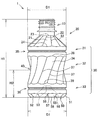
以下に、図面を参照しつつ、本発明の実施形態の詳細を説明する。図1は本実施形態に係るプラスチックボトル1の一例が示された正面図である。図2は図1のプラスチックボトル1の平面図であり、図3は図1のプラスチックボトル1の底面図である。なお、以下では、説明の便宜上、プラスチックボトル1を正立させた図1の状態において、容器内に内容物が充填されるプラスチックボトル1の口部10を上とする。   Hereinafter, the details of the embodiments of the present invention will be described with reference to the drawings. FIG. 1 is a front view showing an example of a plastic bottle 1 according to the present embodiment. 2 is a plan view of the plastic bottle 1 of FIG. 1, and FIG. 3 is a bottom view of the plastic bottle 1 of FIG. In the following, for convenience of explanation, in the state of FIG. 1 in which the plastic bottle 1 is erected, the opening 10 of the plastic bottle 1 in which the contents are filled in the container is referred to as the top.

図1〜図3に示されるように、本実施形態に係るプラスチックボトル1は、無菌充填方式によって内容物が充填されるものであり、口部10と、肩部20と、胴部30と、底部50とを有する。そして、胴部30は、肩部20に連なる上側円筒部31と、上側円筒部31に連なる圧吸収部32と、圧吸収部32に連なる下側円筒部33とを備え、圧吸収部32は、複数の四角形の圧吸収パネル34を周方向に一列に連設して形成される筒形状であり、鉛直方向に両端から中央に向かって胴部30の水平断面形状が縮小するくびれ形状であることを特徴とする。以下では、本実施形態に係るプラスチックボトル1の好適な態様として、圧吸収部32が12枚の同一形状の四角形の圧吸収パネル34から形成される形態を例示し、詳細に説明する。   As shown in FIGS. 1 to 3, the plastic bottle 1 according to the present embodiment is filled with contents by an aseptic filling method, and includes a mouth 10, a shoulder 20, and a body 30. And a bottom portion 50. The body 30 includes an upper cylindrical portion 31 connected to the shoulder portion 20, a pressure absorbing portion 32 connected to the upper cylindrical portion 31, and a lower cylindrical portion 33 connected to the pressure absorbing portion 32. The pressure absorbing portion 32 A plurality of square pressure absorbing panels 34 are formed in a row in the circumferential direction, and has a necked shape in which the horizontal cross-sectional shape of the trunk portion 30 decreases in the vertical direction from both ends toward the center. It is characterized by Below, as a suitable aspect of the plastic bottle 1 which concerns on this embodiment, the form by which the pressure absorption part 32 is formed from the square pressure absorption panel 34 of 12 identical shapes is illustrated and demonstrated in detail.

口部10は、内容物の充填口、及び注出口、あるいは飲み口となり、口部10に、図示せぬキャップが取り付けられることによってプラスチックボトル1が密閉される。なお、上述のように、プラスチックボトル1は無菌充填方式によって内容物が充填されるものであって、口部10には耐熱処理としての結晶化処理(加熱処理)を施す必要がない。   The mouth 10 serves as a filling port, a pouring outlet, or a spout for the contents, and the plastic bottle 1 is sealed by attaching a cap (not shown) to the mouth 10. As described above, the plastic bottle 1 is filled with the contents by the aseptic filling method, and the mouth part 10 does not need to be subjected to the crystallization treatment (heat treatment) as the heat-resistant treatment.

肩部20は、その上方が口部10に連なり、一方で、その下方が胴部30に連なる。肩部20は、上方から下方に向かって拡開する略角錐台の筒形状を有する。図2に示されるように、肩部20は、同一形状の12枚の四角形のパネル21(21A〜21L)から構成される。12枚の四角形のパネル21(21A〜21L)は、周方向に一列に配置され、隣接する各パネル21の側辺22同士が連設される。そして、この12枚の四角形のパネル21(21A〜21L)によって、肩部20の上方から下方に向かって拡開する略12角錐台の筒形状が形成されている。   The upper portion of the shoulder portion 20 is connected to the mouth portion 10, while the lower portion is connected to the trunk portion 30. The shoulder 20 has a substantially truncated pyramidal cylindrical shape that widens downward from above. As shown in FIG. 2, the shoulder portion 20 is composed of twelve rectangular panels 21 (21A to 21L) of the same shape. The twelve rectangular panels 21 (21A to 21L) are arranged in a line in the circumferential direction, and the side edges 22 of the adjacent panels 21 are connected to one another. The twelve rectangular panels 21 (21A to 21L) form a cylindrical shape of a substantially 12-pyramidal shape that widens from the upper side of the shoulder portion 20 to the lower side.

ここで、肩部20を構成する四角形のパネル21について詳述する。図4は図2のIV−IV線拡大断面図であり、1つのパネル21の周方向の中心における鉛直拡大断面を示すものである。   Here, the rectangular panel 21 which constitutes the shoulder portion 20 will be described in detail. FIG. 4 is an enlarged cross-sectional view taken along the line IV-IV in FIG. 2, and shows a vertically enlarged cross section at the center of one panel 21 in the circumferential direction.

図1及び図2に示すように、四角形のパネル21は、周方向へねじられた形状をしている。つまり、パネル21の対向する一対の側辺22は、側辺22と下辺24との交点を通る平面視で径方向に延びる直線L1に対して角度θ1を有する。このような構成にすることで、プラスチックボトル1の鉛直方向に加わる荷重を周方向へ分散することができ、肩部20の強度が向上する。   As shown in FIG. 1 and FIG. 2, the square panel 21 has a circumferentially twisted shape. That is, the pair of opposing side edges 22 of the panel 21 has an angle θ1 with respect to the straight line L1 extending in the radial direction in a plan view passing through the intersection of the side edge 22 and the lower side 24. With such a configuration, the load applied in the vertical direction of the plastic bottle 1 can be dispersed in the circumferential direction, and the strength of the shoulder portion 20 is improved.

四角形のパネル21は、上辺23よりも下辺24が長く、略台形である。そして、下辺24は下方へ向かって湾曲する円弧状であり、プラスチックボトル1の鉛直方向に加わる荷重を吸収することができ、肩部20の強度が向上する。また、鉛直方向の荷重が加わる際、下辺24と側辺22との接点が屈曲点になることを防止でき、肩部20の座屈強度が向上する。   The rectangular panel 21 has a lower side 24 longer than the upper side 23 and is substantially trapezoidal. The lower side 24 is an arc shape which curves downward, can absorb the load applied in the vertical direction of the plastic bottle 1, and the strength of the shoulder 20 is improved. Further, when a load in the vertical direction is applied, the contact between the lower side 24 and the side 22 can be prevented from becoming a bending point, and the buckling strength of the shoulder portion 20 is improved.

なお、側辺22の角度θ1は、特に限定されるものではないが、肩部20の強度の観点から、5度≦θ1≦30度であることが好ましく、10度≦θ1≦20度であることが更に好ましい。角度θ1が5度よりも小であると、肩部20の強度を向上する効果が発揮されにくくなる。一方、角度θ1が30度よりも大であると、肩部20の強度が逆に低下し易くなる。   Although the angle θ1 of the side 22 is not particularly limited, it is preferable that 5 degrees ≦ θ1 ≦ 30 degrees, and 10 degrees ≦ θ1 ≦ 20 degrees from the viewpoint of the strength of the shoulder portion 20. Is more preferred. If the angle θ1 is smaller than 5 degrees, the effect of improving the strength of the shoulder 20 is less likely to be exhibited. On the other hand, if the angle θ1 is larger than 30 degrees, the strength of the shoulder 20 is likely to be reduced.

また、パネル21は、周方向に対向する一対の側辺22から中央に向けて、プラスチックボトル1の内方へ向かって湾曲している。一方で、図4に示すように、径方向においても、パネル21は、上辺23と下辺24から中央に向けて、プラスチックボトル1の内方へ向かって湾曲している。   The panel 21 is curved inward of the plastic bottle 1 from the pair of side edges 22 opposed in the circumferential direction toward the center. On the other hand, as shown in FIG. 4, also in the radial direction, the panel 21 is curved inwardly of the plastic bottle 1 from the upper side 23 and the lower side 24 toward the center.

このような構成にすることで、肩部20の強度が保持されるとともに、プラスチックボトル1の内部の増圧を、後述する圧吸収部32とともに、このパネル21によっても吸収することができる。そして、プラスチックボトル1の強度を保持し、外観を良好に維持することができる。   With such a configuration, the strength of the shoulder portion 20 is maintained, and the pressure buildup inside the plastic bottle 1 can be absorbed by the panel 21 together with the pressure absorbing portion 32 described later. And the intensity | strength of the plastic bottle 1 can be hold | maintained and an external appearance can be maintained favorably.

なお、パネル21の湾曲は、対向する一対の側辺22の周方向の略中央であって、径方向の中央より下辺24側が最大である。そして、対向する一対の側辺22を通る平面から最大湾曲部位までの湾曲量C1は、0.1mm以上かつ3.0mm以下であることが好ましい。湾曲量Cが0.1mmよりも小であると、プラスチックボトル1の内部の増圧を吸収する効果が発揮されにくくなる。一方で、湾曲量Cが3.0mmよりも大であると、肩部20の強度が低下し易くなる。   The curvature of the panel 21 is substantially at the center in the circumferential direction of the pair of side portions 22 facing each other, and the lower side 24 side is the largest from the center in the radial direction. And it is preferable that the curvature amount C1 from the plane which passes a pair of opposing side 22 to a largest curve site | part is 0.1 mm or more and 3.0 mm or less. When the amount of curvature C is smaller than 0.1 mm, the effect of absorbing the pressure buildup inside the plastic bottle 1 is less likely to be exhibited. On the other hand, if the amount of curvature C is larger than 3.0 mm, the strength of the shoulder portion 20 is likely to be reduced.

なお、肩部20は上述の構成に限定されるものではなく、上方が口部10に連なり下方が胴部30に連なる筒形状であれば良く、その形状は特に限定されるものではない。例えば、パネル21は、プラスチックボトル1の外方へ向けて湾曲しても良く、湾曲しない平面状であっても良い。また、肩部20は、複数のパネルから構成されるものではなく、上方から下方へ向かって拡径する略円錐台の筒形状であっても良い。   In addition, the shoulder part 20 is not limited to the above-mentioned structure, What is necessary is just a cylindrical shape in which the upper part is continued by the opening 10 and the lower part is connected with the trunk | drum 30, and the shape is not specifically limited. For example, the panel 21 may be curved toward the outer side of the plastic bottle 1 or may be flat and not curved. Moreover, the shoulder part 20 may not be what is comprised from several panels, and may be a cylinder shape of the substantially truncated cone diameter-expanded toward upper direction from the upper direction.

また、肩部20を構成するパネル21の枚数は、特に限定されるものではないが、4枚以上かつ24枚以下であることが好ましく、12枚がより好ましい。パネル21の枚数が4枚よりも少ないと、肩部20の強度が低下し易くなる。一方で、パネル21の枚数が24枚よりも多いと、パネル21の大きさが小さくり、プラスチックボトル1の内部の増圧を吸収する効果が発揮されにくくなる。   The number of panels 21 constituting the shoulder portion 20 is not particularly limited, but is preferably 4 or more and 24 or less, and more preferably 12. If the number of panels 21 is less than four, the strength of the shoulders 20 is likely to be reduced. On the other hand, when the number of panels 21 is more than 24, the size of the panels 21 is reduced, and the effect of absorbing pressure buildup inside the plastic bottle 1 is less likely to be exhibited.

次に、胴部30は、上述したように、肩部20に連なる上側円筒部31と、上側円筒部31に連なる圧吸収部32と、圧吸収部32に連なる下側円筒部33とを備える。   Next, as described above, the body 30 includes the upper cylindrical portion 31 connected to the shoulder 20, the pressure absorbing portion 32 connected to the upper cylindrical portion 31, and the lower cylindrical portion 33 connected to the pressure absorbing portion 32. .

上側円筒部31は、同一径で鉛直方向に延びる円筒形状である。上側円筒部31には、プラスチックボトル1の内方へ窪んだ環状の周溝35が形成されている。周溝35は、上側円筒部31の鉛直方向の略中央に配設されている。周溝35は、上側円筒部31の水平方向の荷重に対する強度を向上させる。また、周溝35は、鉛直方向の荷重に対して、クッションの役割を果たし、胴部30の座屈を防止する。   The upper cylindrical portion 31 has a cylindrical shape extending in the vertical direction with the same diameter. The upper cylindrical portion 31 is formed with an annular circumferential groove 35 recessed inward of the plastic bottle 1. The circumferential groove 35 is disposed substantially at the center of the upper cylindrical portion 31 in the vertical direction. The circumferential groove 35 improves the strength of the upper cylindrical portion 31 against the load in the horizontal direction. In addition, the circumferential groove 35 plays a role of a cushion against a load in the vertical direction, and prevents the buckling of the trunk portion 30.

圧吸収部32は、12枚の四角形の圧吸収パネル34(34A〜34L)から構成される筒形状である(図6参照)。圧吸収部32は、プラスチックボトル1の内部の増圧を吸収するものであり、詳細については後述する。   The pressure absorbing portion 32 is in the shape of a cylinder formed of twelve square pressure absorbing panels 34 (34A to 34L) (see FIG. 6). The pressure absorbing portion 32 absorbs pressure buildup inside the plastic bottle 1 and will be described later in detail.

下側円筒部33は、上側円筒部31と同様の形状であり、鉛直方向に同一径である円筒形状である。下側円筒部33には、上側円筒部31の周溝35と同様のプラスチックボトル1の内方へ窪んだ環状の周溝36が形成されている。周溝36は、下側円筒部33の鉛直方向の略中央に配設されている。周溝36は、下側円筒部33の水平方向の強度を向上させる。また、周溝36は、鉛直方向の荷重に対して、クッションの役割を果たし、胴部30の座屈を防止する。   The lower cylindrical portion 33 has the same shape as the upper cylindrical portion 31 and has a cylindrical shape having the same diameter in the vertical direction. The lower cylindrical portion 33 is formed with an annular peripheral groove 36 recessed inward of the plastic bottle 1 similar to the peripheral groove 35 of the upper cylindrical portion 31. The circumferential groove 36 is disposed substantially at the center of the lower cylindrical portion 33 in the vertical direction. The circumferential groove 36 improves the strength of the lower cylindrical portion 33 in the horizontal direction. In addition, the circumferential groove 36 acts as a cushion against a load in the vertical direction, and prevents buckling of the trunk 30.

ここで、上側円筒部31の直径と下側円筒部33の直径は同一であり、いずれも胴部30の最大径D1である。したがって、プラスチックボトル1を横に倒した際、上側円筒部31と下側円筒部33とが接地部位となる。また、上側円筒部31と下側円筒部33とは同一の直径D1であるため、プラスチックボトル1が傾くことなく水平に安定して横向きに倒すことができる。さらに、上側円筒部31と下側円筒部33には、補強構造として、環状の周溝35と周溝36がそれぞれ形成され、強度が向上されている。したがって、プラスチックボトル1は、横向きに積載される自動販売機へのベンダー適正が良好である。   Here, the diameter of the upper cylindrical portion 31 and the diameter of the lower cylindrical portion 33 are the same, and both are the maximum diameter D1 of the body portion 30. Therefore, when the plastic bottle 1 is turned to the side, the upper cylindrical portion 31 and the lower cylindrical portion 33 become the ground contact portion. In addition, since the upper cylindrical portion 31 and the lower cylindrical portion 33 have the same diameter D1, the plastic bottle 1 can be horizontally and stably tipped horizontally without tilting. Furthermore, in the upper cylindrical portion 31 and the lower cylindrical portion 33, annular circumferential grooves 35 and circumferential grooves 36 are respectively formed as a reinforcing structure, and the strength is improved. Therefore, the plastic bottle 1 has good vendor suitability to the sideways loaded vending machine.

なお、環状の周溝35と周溝36の構成、例えば、本数、溝の深さ、溝の垂直断面形状などは特に限定されるものではない。上側円筒部31及び下側円筒部33の直径D1やそれぞれの鉛直方向の幅などに応じて適宜設計できる。また、周溝35と周溝36を備えない構成としても良い。なお、横向きに積載される自動販売機へのベンダー適正を良好にする観点から、周溝35と周溝36を少なくとも1本以上形成することが好ましい。   The configuration of the annular circumferential groove 35 and the circumferential groove 36, for example, the number of grooves, the depth of the grooves, the vertical cross-sectional shape of the grooves, etc. are not particularly limited. It can design suitably according to the diameter D1 of the upper side cylindrical part 31 and the lower side cylindrical part 33, the width of each perpendicular direction, etc. Further, the circumferential groove 35 and the circumferential groove 36 may not be provided. In addition, it is preferable to form at least one or more circumferential groove 35 and circumferential groove 36 from the viewpoint of making the vendor appropriate for the vending machine loaded sideways.

底部50は、その上方が胴部30(下側円筒部33)の下方に連なる。隣接する下側円筒部33と、底部50との間には、面取りがなされた面取り部51が形成される。底部50は胴部30に対して垂直方向に伸び、プラスチックボトル1の接地面となる略平板状の底壁52と、底壁52からプラスチックボトル1の内方へ突出するドーム53とを有する。ドーム53は、プラスチックボトル1の径方向へ放射状に延びる5本の放射状リブ54を備える(図3参照)。このドーム53、及び放射状リブ54は、底部50の強度を向上させる。また、面取り部51は、下側円筒部33と底部50との連結部の強度を向上させる。   The bottom portion 50 is continuous with the upper portion below the trunk portion 30 (lower cylindrical portion 33). A chamfered chamfered portion 51 is formed between the adjacent lower cylindrical portion 33 and the bottom portion 50. The bottom portion 50 extends in the vertical direction with respect to the body portion 30 and has a substantially flat bottom wall 52 which is a contact surface of the plastic bottle 1 and a dome 53 projecting inward from the bottom wall 52. The dome 53 includes five radial ribs 54 radially extending in the radial direction of the plastic bottle 1 (see FIG. 3). The domes 53 and the radial ribs 54 improve the strength of the bottom 50. In addition, the chamfered portion 51 improves the strength of the connecting portion between the lower cylindrical portion 33 and the bottom portion 50.

なお、底部50は上述の構成に限定されるものではなく、放射状リブ54の数などは適宜設計できる。なお、奇数本の放射状リブ54を周方向に略均等に備える構成が好ましい。このような構成にすることで、複数の放射状リブ54が径方向に延びる同一直線上に並ぶことがなく、底部50に加わる力を周方向に効果的に分散することができ、底部50の強度が向上する。   Bottom part 50 is not limited to the above-mentioned composition, the number of radial ribs 54, etc. can be designed suitably. It is preferable that the odd number of radial ribs 54 be provided substantially equally in the circumferential direction. With such a configuration, the plurality of radial ribs 54 do not line up on the same straight line extending in the radial direction, the force applied to the bottom portion 50 can be effectively dispersed in the circumferential direction, and the strength of the bottom portion 50 Improve.

ここで、図3に示すように、面取り部51は、同一形状の12枚の四角形のパネル55(55A〜55L)から構成される。面取り部51は、12枚の四角形のパネル55(55A〜55L)が周方向に一列に配置され、隣接する各パネル55の側辺56同士が連設されて形成されている。なお、12枚のパネル55のそれぞれは、後述する圧吸収部30の12枚の圧吸収パネル34のそれぞれの下方に対応して配置されている。   Here, as shown in FIG. 3, the chamfered part 51 is comprised from 12 square panels 55 (55A-55L) of the same shape. The chamfered portion 51 is formed by arranging twelve square panels 55 (55A to 55L) in a row in the circumferential direction, and connecting the side edges 56 of the adjacent panels 55 to one another. Each of the twelve panels 55 is disposed corresponding to the lower side of each of the twelve pressure absorbing panels 34 of the pressure absorbing portion 30 described later.

また、四角形のパネル55は、上辺57よりも下辺58が短く、略台形状である。上辺57は、上方へ向かって湾曲する円弧状であり、プラスチックボトル1の鉛直方向に加わる荷重を吸収することができ、下側円筒部33と底部50との連結部の強度をより向上することができる。   The rectangular panel 55 has a lower side 58 shorter than the upper side 57 and is substantially trapezoidal. The upper side 57 has an arc shape which curves upward, can absorb the load applied in the vertical direction of the plastic bottle 1, and further improves the strength of the connecting portion between the lower cylindrical portion 33 and the bottom portion 50. Can.

なお、面取り部51は上述の構成に限定されるものではなく、パネル55の枚数などは適宜設計できる。例えば、面取り部51は、複数のパネルから構成されるものではなく、上方から下方へ縮径する略円錐台形状であっても良い。また、面取り部51は、面取りに替わってR取りされた形状であっても良い。   In addition, the chamfered part 51 is not limited to the above-mentioned structure, The number of sheets of the panel 55 etc. can be designed suitably. For example, the chamfered portion 51 may not have a plurality of panels, and may have a substantially frusto-conical shape whose diameter decreases from the upper side to the lower side. Further, the chamfered portion 51 may be rounded in place of chamfering.

次に、圧吸収部32の詳細について説明する。図5は圧吸収部32の拡大図であり、図6は図5のVI−VI線断面図である。なお、図6は、圧吸収部32の鉛直方向の中央での断面図である。   Next, the pressure absorbing portion 32 will be described in detail. FIG. 5 is an enlarged view of the pressure absorbing portion 32, and FIG. 6 is a cross-sectional view taken along the line VI-VI of FIG. FIG. 6 is a cross-sectional view of the pressure absorbing portion 32 at the center in the vertical direction.

上述したように、圧吸収部32は、同一形状の12枚の四角形の圧吸収パネル34(34A〜34L)から構成される。12枚の四角形の圧吸収パネル34(34A〜34L)は、周方向に一列に配置され、隣接する各圧吸収パネル34の側辺37同士が連設される。そして、圧吸収部32は、連設された12枚の四角形の圧吸収パネル34(34A〜34L)によって、筒形状に形成されている。つまり、圧吸収部32は、水平断面形状が12角形の筒形状である。また、圧吸収部32は、鉛直方向に上下両端から中央に向かって水平断面形状が縮小するくびれ形状である。そして、圧吸収部30の鉛直方向の中央が最もくびれた最大くびれ部40であり、圧吸収部32は鉛直方向で対称にくびれている。   As described above, the pressure absorbing portion 32 is configured of twelve square pressure absorbing panels 34 (34A to 34L) of the same shape. Twelve square pressure-absorbing panels 34 (34A to 34L) are arranged in a line in the circumferential direction, and the side edges 37 of the adjacent pressure-absorbing panels 34 are continuously provided. And the pressure absorption part 32 is formed in a cylinder shape by 12 square pressure absorption panels 34 (34A-34L) provided in series. That is, the pressure absorbing portion 32 is a cylindrical shape having a dodecagonal horizontal sectional shape. Further, the pressure absorbing portion 32 has a necked shape in which the horizontal cross-sectional shape decreases in the vertical direction from the upper and lower ends toward the center. The vertical center of the pressure absorbing portion 30 is the largest constricted portion 40 which is the most constricted, and the pressure absorbing portion 32 is symmetrical in the vertical direction.

ここで、圧吸収パネル34は、上述の肩部20のパネル21と同様に、周方向へねじられた形状をしている。そして、各圧吸収パネル34の周方向に対向する一対の側辺37は、最大くびれ部40において、鉛直線L2に対して周方向に角度θ2を有する。また、圧吸収パネル34は、上辺38と下辺39とが同一の長さであり、略平行四辺形である。また、圧吸収パネル34は、周方向に対向する一対の側辺37から中央に向けてプラスチックボトル1の内方へ湾曲し、周方向の中央が最も湾曲している。   Here, the pressure-absorbing panel 34 has a circumferentially twisted shape, similar to the panel 21 of the shoulder 20 described above. And in the largest constriction part 40, a pair of side 37 which counters the circumferential direction of each pressure absorption panel 34 has angle theta 2 of the peripheral direction to perpendicular line L2. Further, in the pressure absorbing panel 34, the upper side 38 and the lower side 39 have the same length and are substantially parallelograms. Further, the pressure absorbing panel 34 is curved inward of the plastic bottle 1 from the pair of side edges 37 opposed in the circumferential direction toward the center, and the center in the circumferential direction is most curved.

なお、上辺38は上方へ湾曲する円弧状であり、下辺39は下方へ湾曲する円弧状である。したがって、プラスチックボトル1の鉛直方向に加わる荷重をこの円弧状の上辺38と下辺39とによって吸収することができ、圧吸収部32の座屈強度が向上する。また、鉛直方向の荷重が加わる際、上辺38または下辺39と、側辺37との接点が屈曲点になることを防止でき、圧吸収部32の座屈強度が向上する。   The upper side 38 has an arc shape curving upward, and the lower side 39 has a circular arc shape curving downward. Therefore, the load applied in the vertical direction of the plastic bottle 1 can be absorbed by the arc-shaped upper side 38 and the lower side 39, and the buckling strength of the pressure absorbing portion 32 is improved. In addition, when a load in the vertical direction is applied, the contact between the upper side 38 or the lower side 39 and the side 37 can be prevented from becoming a bending point, and the buckling strength of the pressure absorbing portion 32 is improved.

ここで、プラスチックボトル1の内部の圧力は、内容物の温度が充填時よりも上昇する場合、内容物の体積が膨張して増加する。内部で増圧が生じたプラスチックボトル1は内部から外方へ押圧されて変形が生じる。この時、圧吸収パネル34は、外方へ向けて押圧されてたわむ。そして、圧吸収部32は、圧吸収パネル34が外方へ向けてたわむことにより、プラスチックボトル1の内部の増圧による荷重の一部を吸収し、プラスチックボトル1の全体の変形を防止する役割を果たす。なお、圧吸収パネル34は、内方へ湾曲して構成されているため、より効果的に内部の増圧を吸収することができる。   Here, the pressure inside the plastic bottle 1 expands and increases the volume of the content when the temperature of the content rises above that at the time of filling. The internally pressurized plastic bottle 1 is pressed outward from the inside to cause deformation. At this time, the pressure absorbing panel 34 is pressed outward and flexed. The pressure absorbing portion 32 functions to absorb a part of the load due to the pressure buildup inside the plastic bottle 1 by the pressure absorbing panel 34 being bent outward, and to prevent the overall deformation of the plastic bottle 1. Play. In addition, since the pressure absorption panel 34 is curved inward, the internal pressure increase can be absorbed more effectively.

したがって、本実施形態に係るプラスチックボトル1は、加温時におけるプラスチックボトル1の内部の増圧を圧吸収パネル34によって効果的に吸収することができ、プラスチックボトル1の全体の変形を防止して外観を良好に維持することができ、自動販売機による加温状態でのベンダー適正を備えることができる。   Therefore, the plastic bottle 1 according to the present embodiment can effectively absorb the pressure buildup inside the plastic bottle 1 at the time of heating by the pressure absorption panel 34, and prevents the overall deformation of the plastic bottle 1. The appearance can be kept good and the vending machine can provide vendor compliance in a heated condition.

なお、圧吸収部32の鉛直方向の中央(最大くびれ部40)における、圧吸収パネル34の対向する一対の側辺37を通る水平線から最大湾曲部位までの湾曲量C2は、0.1mm以上かつ5.0mm以下とすることが好ましい。湾曲量C2が0.1mmよりも小であると、プラスチックボトル1の内部の増圧を効果的に吸収する効果が発揮されにくくなる。一方で、湾曲量C2が5.0mmよりも大であると、胴部30の強度が低下し易くなる。   The amount of curvature C2 from the horizontal line passing through the opposing side 37 of the pressure-absorbing panel 34 to the maximum bending site at the vertical center (maximum constriction 40) of the pressure-absorbing portion 32 is 0.1 mm or more and It is preferable to set it as 5.0 mm or less. If the amount of curvature C2 is smaller than 0.1 mm, the effect of effectively absorbing the pressure buildup inside the plastic bottle 1 is less likely to be exhibited. On the other hand, if the amount of curvature C2 is larger than 5.0 mm, the strength of the body 30 is likely to be reduced.

ここで、圧吸収部32を構成する圧吸収パネル34の枚数は、特に限定されるものではないが、4枚以上かつ24枚以下であることが好ましく、12枚がより好ましい。圧吸収パネル34の枚数が4枚よりも少ないと、圧吸収部32の鉛直方向に対する強度が低下し易くなる。一方で、圧吸収パネル34の枚数が24枚よりも多いと、圧吸収パネル34の大きさが小さくなり、プラスチックボトル1の内部の増圧を吸収する効果が発揮されにくくなる。   Here, the number of the pressure absorbing panels 34 constituting the pressure absorbing portion 32 is not particularly limited, but is preferably 4 or more and 24 or less, and more preferably 12 or less. If the number of pressure absorbing panels 34 is smaller than four, the strength of the pressure absorbing portion 32 in the vertical direction tends to be reduced. On the other hand, when the number of pressure absorbing panels 34 is more than 24, the size of the pressure absorbing panel 34 is reduced, and the effect of absorbing the pressure buildup inside the plastic bottle 1 is less likely to be exhibited.

また、圧吸収パネル34の大きさは、特に限定されるものではない。しかし、圧吸収パネル34の上辺38と下辺39との鉛直距離S1と、プラスチックボトル1の全高H1との比S1/H1(鉛直方向)は、0.25以上かつ0.6以下とすることが好ましい。比S1/H1が0.6よりも大であると、圧吸収部32の鉛直方向に対する強度が低下し易くなる。一方、比S1/H1が0.25よりも小であると、プラスチックボトル1の内部の増圧を吸収する効果が発揮されにくくなる。   Also, the size of the pressure absorbing panel 34 is not particularly limited. However, the ratio S1 / H1 (vertical direction) of the vertical distance S1 between the upper side 38 and the lower side 39 of the pressure absorbing panel 34 and the total height H1 of the plastic bottle 1 may be 0.25 or more and 0.6 or less preferable. When the ratio S1 / H1 is larger than 0.6, the strength of the pressure absorbing portion 32 in the vertical direction is likely to be reduced. On the other hand, when the ratio S1 / H1 is smaller than 0.25, the effect of absorbing the pressure buildup inside the plastic bottle 1 is less likely to be exhibited.

なお、圧吸収部32は、大きさや形状がそれぞれ異なる複数の四角形のパネルから構成されるものであっても良いが、同一形状の複数の四角形のパネルから構成されることが好ましい。このような構成にすることで、圧吸収部32の強度が周方向で均等化されるとともに、プラスチックボトル1の内部の増圧を周方向に分散して吸収することができ、プラスチックボトル1の強度が向上する。また、プラスチックボトル1の形状が安定し、賦形不良が発生しにくく、歩留まりが向上する。   The pressure absorbing portion 32 may be formed of a plurality of square panels having different sizes and shapes, but is preferably formed of a plurality of square panels having the same shape. With such a configuration, the strength of the pressure absorbing portion 32 can be equalized in the circumferential direction, and the pressure buildup inside the plastic bottle 1 can be dispersed and absorbed in the circumferential direction. Strength is improved. In addition, the shape of the plastic bottle 1 is stabilized, deformation defects are less likely to occur, and the yield is improved.

ここで、圧吸収部32は、鉛直方向に上下両端から中央に向かって水平断面形状が縮小するくびれ形状である。したがって、このくびれ形状である圧吸収部32を親指と親指以外の指とで挟み込むようにして握ることで、プラスチックボトル1を安定して把持することができる。つまり、プラスチックボトル1は、胴部30の持ち易さに優れ、持ち運び、内容物の取り出し、口部10に取り付けられる図示せぬキャップの開栓及び閉栓動作などが容易となり、取り扱い性に優れる。また、圧吸収部32は内方へ湾曲する圧吸収パネル34によって構成されているため、上述のように圧吸収部32を把持した際、圧吸収パネル34の側辺37に指が引っ掛かり、さらに安定して把持することができる。   Here, the pressure absorbing portion 32 has a constricted shape in which the horizontal cross-sectional shape decreases in the vertical direction from the upper and lower ends toward the center. Therefore, the plastic bottle 1 can be stably gripped by holding the pressure absorbing portion 32 having the necked shape between the thumb and a finger other than the thumb. That is, the plastic bottle 1 is excellent in the ease of holding the body 30, is easy to carry, takes out the contents, and facilitates opening and closing operations of a cap (not shown) attached to the mouth 10 and is excellent in handleability. Further, since the pressure absorbing portion 32 is constituted by the pressure absorbing panel 34 which curves inward, when gripping the pressure absorbing portion 32 as described above, a finger is caught on the side 37 of the pressure absorbing panel 34, and further, It can be stably held.

なお、圧吸収部32のくびれ形状は限定されるものではない。しかし、上述のように、圧吸収部32の鉛直方向の中央が最もくびれ、鉛直方向で略対称であることが好ましい。このような構成にすることで、圧吸収部32の強度は鉛直方向で均等化され、応力の集中が生じにくくなり、プラスチックボトル1の強度が向上する。また、圧吸収部32によるプラスチックボトル1の内部の増圧の吸収は、鉛直方向で均等化されるので、増圧の吸収効果が向上する。   In addition, the constriction shape of the pressure absorption part 32 is not limited. However, as described above, it is preferable that the center in the vertical direction of the pressure absorbing portion 32 be the most narrow and substantially symmetrical in the vertical direction. With such a configuration, the strength of the pressure absorbing portion 32 is equalized in the vertical direction, stress concentration is less likely to occur, and the strength of the plastic bottle 1 is improved. Further, since the absorption of the pressure buildup inside the plastic bottle 1 by the pressure absorbing portion 32 is equalized in the vertical direction, the absorption effect of the pressure buildup is improved.

なお、最大くびれ部40での圧吸収部32の径、つまり、最大くびれ部40での圧吸収パネル34の内接円の径D2と、胴部30の最大径D1との比D2/D1は、0.65以上かつ0.95以下とすることが好ましい。比D2/D1が0.95よりも大であると、くびれ形状が小さくなってプラスチックボトル1の持ち易さが向上する効果が発揮されにくくなる。一方、比D2/D1が0.65よりも小であると、くびれ形状が大きくなって圧吸収部32の強度が低下し易くなる。   The diameter D2 of the pressure absorbing portion 32 at the maximum constriction 40, that is, the ratio D2 / D1 of the diameter D2 of the inscribed circle of the pressure absorbing panel 34 at the maximum constriction 40 and the maximum diameter D1 of the body 30 is It is preferable to set it as 0.65 or more and 0.95 or less. When the ratio D2 / D1 is larger than 0.95, the shape of the constriction becomes small, and the effect of improving the ease of holding the plastic bottle 1 becomes difficult to be exhibited. On the other hand, if the ratio D2 / D1 is smaller than 0.65, the necked shape becomes large and the strength of the pressure absorbing portion 32 is likely to be reduced.

また、底部50の接地面52から圧吸収部32の最大くびれ部40までの高さH2と、プラスチックボトル1の全高H1との比H2/H1は、0.3以上かつ0.5以下とすることが好ましい。比H2/H1が0.5よりも大であると、最大くびれ部40がプラスチックボトル1の上側に位置することになり、上側円筒部31または圧吸収部32が小さくなり、プラスチックボトル1の強度が低下し易くなる。一方、比H2/H1が0.3よりも小であると、最大くびれ部40がプラスチックボトル1の下側に位置することになり、圧吸収部32または下側円筒部33が小さくなり、プラスチックボトル1の強度が低下し易くなる。また、プラスチックボトル1の重心が高くなり、内容物を充填したプラスチックボトル1の搬送時にプラスチックボトル1が転倒し易くなる。   Further, the ratio H2 / H1 of the height H2 from the ground contact surface 52 of the bottom 50 to the maximum constriction 40 of the pressure absorbing portion 32 and the total height H1 of the plastic bottle 1 is 0.3 or more and 0.5 or less. Is preferred. When the ratio H2 / H1 is larger than 0.5, the largest constricted portion 40 is located on the upper side of the plastic bottle 1, the upper cylindrical portion 31 or the pressure absorbing portion 32 becomes smaller, and the strength of the plastic bottle 1 Tends to decrease. On the other hand, when the ratio H2 / H1 is smaller than 0.3, the largest constricted portion 40 is located below the plastic bottle 1, and the pressure absorbing portion 32 or the lower cylindrical portion 33 becomes smaller, so that plastic The strength of the bottle 1 tends to decrease. In addition, the center of gravity of the plastic bottle 1 is increased, and the plastic bottle 1 is easily tumbled when the plastic bottle 1 filled with the contents is transported.

なお、プラスチックボトル1は、圧吸収部32がくびれ形状であるので、鉛直方向に加わる荷重やプラスチックボトル1の内部の増圧による押圧が作用した際、最大くびれ部40に応力が集中し易い。しかし、くびれ形状を形成する圧吸収パネル34は、周方向へねじられた形状であり、側辺37は、鉛直線L2に対して周方向に角度θ2を有するので、最大くびれ部40に加わる力を周方向に効果的に分散することができ、圧吸収部32の強度が向上し、圧吸収部32の座屈変形が防止される。したがって、周方向へねじられた圧吸収パネル34を備える構成によって、強度を保持しながら圧吸収部32をくびれ形状とすることができる。なお、この角度θ2は、圧吸収パネル34の周方向のねじり量を表している。   In the plastic bottle 1, since the pressure absorbing portion 32 has a constricted shape, stress is likely to be concentrated on the largest constricted portion 40 when a load applied in the vertical direction or a pressure due to pressure increase inside the plastic bottle 1 acts. However, the pressure absorbing panel 34 forming the constriction shape is a shape twisted in the circumferential direction, and the side 37 has an angle θ 2 in the circumferential direction with respect to the vertical line L 2, so the force applied to the largest constricted portion 40 Can be effectively dispersed in the circumferential direction, the strength of the pressure absorbing portion 32 is improved, and buckling deformation of the pressure absorbing portion 32 is prevented. Therefore, by the structure provided with the pressure absorption panel 34 twisted in the circumferential direction, the pressure absorption part 32 can be made into a necked shape, maintaining strength. The angle θ2 represents the amount of twisting of the pressure absorbing panel 34 in the circumferential direction.

側辺37の角度θ2は、強度を保持しながら圧吸収部32をくびれ形状とする観点から、5度≦θ2≦30度であることが好ましく、角度θ2は15度であることが更に好ましい。角度θ2が5度よりも小であると、圧吸収部32の応力の集中を防止する効果が発揮されにくくなる。一方で、角度θ2が30度よりも大であると、圧吸収部30の強度、特に座屈強度が低下し易くなる。また、賦形性が悪くなりやすい。   The angle θ2 of the side 37 is preferably 5 degrees ≦ θ2 ≦ 30 degrees from the viewpoint of forming the pressure absorbing portion 32 in a necked shape while maintaining strength, and the angle θ2 is more preferably 15 degrees. When the angle θ2 is smaller than 5 degrees, the effect of preventing concentration of stress of the pressure absorbing portion 32 is less likely to be exhibited. On the other hand, when the angle θ2 is larger than 30 degrees, the strength of the pressure absorbing portion 30, in particular, the buckling strength tends to decrease. In addition, the shapeability tends to deteriorate.

ここで、肩部20を構成する四角形のパネル21は、周方向へねじられた形状をしている。また、圧吸収部32を構成する四角形の圧吸収パネル34も、周方向へねじられた形状をしている。そして、四角形のパネル21と圧吸収パネル34のねじりは対応しており、プラスチックボトル1は、上方から下方へ肩部20と圧吸収部32とが連動して周方向にねじられた形状である。つまり、圧吸収部32の圧吸収パネル34(34A〜34L)のそれぞれは、肩部20のパネル21(21A〜21L)のそれぞれに対応して配置される。例えば、上方から下方へ向かって、パネル21Aは圧吸収パネル34Aに、パネル21Bは圧吸収パネル34Bに、パネル21Cは圧吸収パネル34Cにと対応している。さらに、圧吸収部32の下方に位置する面取り部51を構成するパネル55のそれぞれは、圧吸収パネル34(34A〜34L)のそれぞれに対応している。したがって、プラスチックボトル1は、購買者の目を引いたり奪ったりする効果であるアイキャッチ性に優れている。   Here, the square panel 21 that constitutes the shoulder portion 20 has a shape that is twisted in the circumferential direction. Moreover, the square pressure absorption panel 34 which comprises the pressure absorption part 32 is also carrying out the shape twisted in the circumferential direction. The torsion of the rectangular panel 21 and the pressure absorbing panel 34 correspond to each other, and the plastic bottle 1 has a shape in which the shoulder portion 20 and the pressure absorbing portion 32 are interlocked and twisted in the circumferential direction from the upper side to the lower side. . That is, each of the pressure absorbing panels 34 (34A to 34L) of the pressure absorbing portion 32 is arranged corresponding to each of the panels 21 (21A to 21L) of the shoulder portion 20. For example, from top to bottom, the panel 21A corresponds to the pressure absorption panel 34A, the panel 21B corresponds to the pressure absorption panel 34B, and the panel 21C corresponds to the pressure absorption panel 34C. Furthermore, each of the panel 55 which comprises the chamfered part 51 located under the pressure absorption part 32 respond | corresponds to each of the pressure absorption panel 34 (34A-34L). Therefore, the plastic bottle 1 is excellent in eye catching property which is an effect of attracting and detracting from the buyer.

本実施形態に係るプラスチックボトル1にはサイズによる限定はなく、種々のサイズに対して適用することができるが、プラスチックボトル1の内容量が150ml〜1000mlであるプラスチックボトル1に対して好適である。とりわけ、プラスチックボトル1の全高H1が100mm〜250mmであり、胴部30の最大径が45mm〜100mmであることが好ましく、本実施形態に係るプラスチックボトル1の奏する効果を好適に得ることができる。   The plastic bottle 1 according to the present embodiment is not limited by the size and can be applied to various sizes, but the plastic bottle 1 is suitable for the plastic bottle 1 having an internal volume of 150 ml to 1000 ml. . In particular, the total height H1 of the plastic bottle 1 is preferably 100 mm to 250 mm, and the maximum diameter of the body portion 30 is preferably 45 mm to 100 mm. The advantageous effects of the plastic bottle 1 according to the present embodiment can be suitably obtained.

プラスチックボトル1を構成する熱可塑性樹脂として、例えば、ポリエチレンテレフタレート、ポリブチレンテレフタレート、ポリエチレンナフタレート、ポリカーボネート、ポリアリレート、又はこれらの共重合体等の熱可塑性ポリエステル、これらの樹脂、あるいは他の樹脂とのブレンド物が好適であり、特に、ポリエチレンテレフタレート等のエチレンテレフタレート系熱可塑性ポリエステルを好適に使用することができる。更に、アクリロニトリル樹脂、ポリエチレン、ポリプロピレン、プロピレン−エチレン共重合体等も使用することができる。更に、植物由来のバイオマス系プラスチック、例えば、ポリ乳酸(PLA)を用いることも可能である。上述された樹脂には、成形品の品質を損なわない範囲で、種々の添加剤、例えば、着色剤、紫外線吸収剤、離型剤、滑剤、核剤、酸化防止剤、帯電防止剤等を配合することができる。   The thermoplastic resin constituting the plastic bottle 1 is, for example, thermoplastic polyester such as polyethylene terephthalate, polybutylene terephthalate, polyethylene naphthalate, polycarbonate, polyarylate, or a copolymer thereof, these resins, or other resins Blends of the above are preferable, and in particular, ethylene terephthalate thermoplastic polyester such as polyethylene terephthalate can be suitably used. Furthermore, acrylonitrile resin, polyethylene, polypropylene, propylene-ethylene copolymer and the like can also be used. Furthermore, it is also possible to use plant-based biomass-based plastics, such as polylactic acid (PLA). The above-mentioned resin is blended with various additives, for example, a coloring agent, an ultraviolet absorber, a releasing agent, a lubricant, a nucleating agent, an antioxidant, an antistatic agent, etc., as long as the quality of the molded product is not impaired. can do.

プラスチックボトル1を構成するエチレンテレフタレート系熱可塑性樹脂として、エステル反復部分の大部分、一般に70モル%以上をエチレンテレフタレート単位が占めるものであり、ガラス転移点(Tg)が50〜90℃であり、融点(Tm)が200〜275℃の範囲にあるものが好適である。また、エチレンテレフタレート系熱可塑性ポリエステルとして、ポリエチレンテレフタレートが耐圧性等の点で特に優れているものの、エチレンテレフタレート単位以外に、イソフタル酸や、ナフタレンジカルボン酸等の二塩基酸と、プロピレングリコール等のジオールからなるエステル単位を少量含む共重合ポリエステルも使用することができる。   The ethylene terephthalate-based thermoplastic resin constituting the plastic bottle 1 is such that the ethylene terephthalate unit occupies most of the ester repeating portion, generally 70 mol% or more, and the glass transition point (Tg) is 50 to 90 ° C. Those having a melting point (Tm) in the range of 200 to 275 ° C. are preferred. Moreover, although polyethylene terephthalate is particularly excellent in terms of pressure resistance etc. as an ethylene terephthalate thermoplastic polyester, in addition to ethylene terephthalate units, dibasic acids such as isophthalic acid and naphthalene dicarboxylic acid and diols such as propylene glycol Copolyesters containing a small amount of ester units consisting of can also be used.

更に、プラスチックボトル1は、二層以上の熱可塑性ポリエステル層により構成することもできる。更に、プラスチックボトル1は、二層以上の熱可塑性ポリエステル層により構成する場合には、層間にバリア層や、酸素吸収層等の中間層を備えることができる。酸素吸収層としては、酸化可能有機成分、及び遷移金属触媒の組み合わせ、あるいは実質的に酸化しないガスバリア性樹脂等を含む層を使用することができる。   Furthermore, the plastic bottle 1 can also be composed of two or more thermoplastic polyester layers. Furthermore, the plastic bottle 1 can be equipped with intermediate layers, such as a barrier layer and an oxygen absorption layer, between layers, when it comprises by the thermoplastic polyester layer of two or more layers. As the oxygen absorbing layer, a layer containing a combination of an oxidizable organic component and a transition metal catalyst or a gas barrier resin which does not substantially oxidize can be used.

プラスチックボトル1は、上述の材料を射出成形して製作したプリフォームをブロー成形によって成形することにより作製することができる。   The plastic bottle 1 can be produced by blow molding a preform produced by injection molding the above-mentioned material.

以上に説明がなされたように、本実施形態に係るプラスチックボトル1は、胴部30は、肩部20に連なる上側円筒部31と、上側円筒部31に連なる圧吸収部32と、圧吸収部32に連なる下側円筒部33とを備え、圧吸収部32は、複数の四角形の圧吸収パネル34を周方向に一列に連設して形成される筒形状であり、鉛直方向に両端から中央に向かって水平断面形状が縮小するくびれ形状である。そして、本実施形態に係る構成によれば、軽量化されたプラスチックボトル1に対して、内容物が充填された後に自動販売機などによって加温される際のプラスチックボトル1の内部の増圧を吸収して外観を良好に維持でき、薄肉化されても強度を保持して自動販売機による加温状態でのベンダー適正を有し、持ち易さが優れる。   As described above, in the plastic bottle 1 according to the present embodiment, the body 30 includes the upper cylindrical portion 31 connected to the shoulder portion 20, the pressure absorbing portion 32 connected to the upper cylindrical portion 31, and the pressure absorbing portion The pressure absorbing portion 32 is a cylindrical shape formed by connecting a plurality of square pressure absorbing panels 34 in a row in the circumferential direction, and the pressure absorbing portion 32 vertically extends from both ends to the center The horizontal cross-sectional shape is narrowed toward the end. And according to the structure which concerns on this embodiment, the pressure increase inside the plastic bottle 1 at the time of being heated by a vending machine etc. after the content was filled with respect to the plastic bottle 1 reduced in weight is obtained. It can be absorbed to maintain its good appearance, maintain its strength even if it is thinned, and has bender suitability in a heated state by a vending machine, and is easy to hold.

以下に、実施例を示して、本発明を更に詳細、かつ具体的に説明する。しかしながら、本発明は、以下の実施例に限定されるものではない。   Hereinafter, the present invention will be described in more detail and specifically by showing examples. However, the present invention is not limited to the following examples.

[実施例1]
図1に示される本実施形態に係るプラスチックボトル1が用いられた。すなわち、プラスチックボトル1は、圧吸収部30が、12枚の四角形の圧吸収パネル34を周方向に一列に連設して形成される筒形状であり、鉛直方向に両端から中央に向かって水平断面形状が縮小するくびれ形状であるといった特徴を有している。プラスチックボトル1は、ポリエチレンテレフタレート製であり、重量が21.8gで、容量が300mlであった。また、プラスチックボトル1は、全高H1が134mmで、胴部30の最大径D1が66mmで、接地面52から最大くびれ部40までの高さH2が52mmで、最大くびれ部40での径D2が55mmであった。プラスチックボトル1は、プリフォームをブロー成形することによって作製された。
Example 1
The plastic bottle 1 according to the present embodiment shown in FIG. 1 was used. That is, the plastic bottle 1 has a cylindrical shape in which the pressure absorbing portion 30 is formed by connecting twelve square pressure absorbing panels 34 in a row in the circumferential direction, and is horizontal from the both ends toward the center in the vertical direction It is characterized in that the cross-sectional shape is a constricted shape which reduces. The plastic bottle 1 was made of polyethylene terephthalate, and had a weight of 21.8 g and a volume of 300 ml. The plastic bottle 1 has a total height H1 of 134 mm, a maximum diameter D1 of the body 30 of 66 mm, a height H2 from the ground plane 52 to the maximum constriction 40 of 52 mm, and a diameter D2 at the maximum constriction 40 It was 55 mm. The plastic bottle 1 was produced by blow molding a preform.

(加温時外観確認試験)
実施例1のプラスチックボトル1にヘッドスペースが20mlになるように室温が23℃の無菌室における無菌充填方式によって緑茶を充填し、口部10をキャップによって密封した。この内容物が無菌充填方式によって充填されたプラスチックボトル1を液温が70℃となるようにホットプレート上にて加温した。この時、プラスチックボトル1の外観は良好に維持された。
(Examination test during heating)
Green tea was filled into the plastic bottle 1 of Example 1 by an aseptic filling method in a sterile room at a room temperature of 23 ° C. so that the head space was 20 ml, and the mouth 10 was sealed by a cap. This content was heated on a hot plate so that the plastic bottle 1 filled with the aseptic filling method would have a liquid temperature of 70.degree. At this time, the appearance of the plastic bottle 1 was maintained well.

(常温時外観確認試験)
上述の70℃に加温したプラスチックボトル1を密閉された状態で常温(23℃)下に静置した。この時、プラスチックボトル1の外観は良好に維持された。
(Examination test at normal temperature)
The plastic bottle 1 heated to 70 ° C. described above was allowed to stand still at room temperature (23 ° C.) in a closed state. At this time, the appearance of the plastic bottle 1 was maintained well.

(自動販売機のベンダー特性試験)
実施例1のプラスチックボトル1にヘッドスペースが20mlになるように室温が23℃の無菌室における無菌充填方式によって緑茶を充填し、口部10をキャップによって密封した。この内容物が無菌充填方式によって充填されたプラスチックボトル1を富士電機製自動販売機に最大装填可能数となるまで装填し、液温が55℃となるように加温した状態で払い出しを行った。この時、プラスチックボトル1の自動販売機への装填、及び自動販売機からの払い出しは問題なく行われた。また、自動販売機から払い出されたプラスチックボトル1の外観は良好に維持された。
(Vendor characteristic test of vending machine)
Green tea was filled into the plastic bottle 1 of Example 1 by an aseptic filling method in a sterile room at a room temperature of 23 ° C. so that the head space was 20 ml, and the mouth 10 was sealed by a cap. The plastic bottle 1 filled with the contents by the aseptic filling method was loaded into the Fuji Electric vending machine to the maximum loadable number, and was dispensed in a heated state so that the liquid temperature would be 55 ° C. . At this time, loading of the plastic bottle 1 into the vending machine and delivery from the vending machine were performed without any problem. In addition, the appearance of the plastic bottle 1 dispensed from the vending machine was well maintained.

(把持性試験)
実施例1のプラスチックボトル1にヘッドスペースが20mlになるように室温が23℃の無菌室における無菌充填方式によって緑茶を充填し、口部10をキャップによって密封した。この内容物が無菌充填方式によって充填されたプラスチックボトル1を液温が70℃となるようにホットプレート上にて加温した。この加温されたプラスチックボトル1について、100人のモニターによって、持ち易さ、キャップの回動による開栓及び閉栓のし易さについて評価した。表1に結果を示す。評価結果は、○:容易、△:困難ではないが容易でもない、×:困難、で表記する。
(Gripping test)
Green tea was filled into the plastic bottle 1 of Example 1 by an aseptic filling method in a sterile room at a room temperature of 23 ° C. so that the head space was 20 ml, and the mouth 10 was sealed by a cap. This content was heated on a hot plate so that the plastic bottle 1 filled with the aseptic filling method would have a liquid temperature of 70.degree. The heated plastic bottle 1 was evaluated by a 100-person monitor for ease of holding, easy opening and closing of the cap by turning. Table 1 shows the results. Evaluation results are indicated as follows: ○: easy, Δ: not difficult but not easy, ×: difficult.

Figure 0006531401
Figure 0006531401

上述された実施例から以下の点が導き出された。実施例1は、無菌充填方式によって内容物が充填された場合において、加温状態における外観を良好に維持できるととともに、加温状態でのベンダー適正を満たすだけの強度を有していた。さらに、実施例1は、胴部の把持性が良好であり、キャップの回動による開栓及び閉栓動作が容易であった。   The following points have been derived from the embodiment described above. In Example 1, when the contents were filled by the aseptic filling method, the appearance in the heated state could be well maintained, and the strength was sufficient to satisfy the bender suitability in the heated state. Furthermore, in Example 1, the gripability of the body portion was good, and the opening and closing operations by turning the cap were easy.

上述された実施例から、本実施形態に係るプラスチックボトル1は、その構成によって、軽量化されたプラスチックボトルにおいて、無菌充填方式によって内容物が充填された後に加温される際のプラスチックボトルの内部の増圧を吸収して外観を良好に維持でき、薄肉化されても強度を保持して自動販売機による加温状態でのベンダー適正を有し、持ち易さが優れるものであるとことが示された。   From the example described above, the plastic bottle 1 according to this embodiment is a lightweight plastic bottle according to its configuration, and the inside of the plastic bottle when the contents are filled by the aseptic filling method and then warmed Can absorb the pressure buildup and maintain good appearance, maintain strength even when thinned, and have bender suitability in a heated state by the vending machine, and have excellent ease of holding Indicated.

本開示は、無菌充填後に加温されるプラスチックボトルに好適に利用することができる。しかしながら、本開示は、上述された実施形態、及び実施例に限定されるものではない。本開示のプラスチックボトルは、内容物に、例えば、緑茶、ウーロン茶、紅茶、コーヒー、果汁等の各種非炭酸飲料、あるいはしょうゆ、ソース、みりん等の調味料、その他を収容した、あらゆる容器に有用であり、容器の横倒し積載が可能であるので自動販売機等による加温販売にも適している。   The present disclosure can be suitably utilized for plastic bottles that are warmed after aseptic filling. However, the present disclosure is not limited to the above-described embodiments and examples. The plastic bottle of the present disclosure is useful for any container that contains various non-carbonated beverages such as green tea, oolong tea, black tea, coffee, fruit juice, or soy sauce, sauces, seasonings such as mirin, etc. in the contents. Because the container can be loaded sideways, it is also suitable for heating and selling with a vending machine or the like.

1 プラスチックボトル
10 口部
20 肩部
30 胴部
31 上側円筒部
32 圧吸収部
33 下側円筒部
34 圧吸収パネル
35 周溝
36 周溝
37 側辺
38 上辺
39 下辺
40 最大くびれ部
50 底部
D1 胴部の最大径
D2 最大くびれ部の径
H1 プラスチックボトルの全高
H2 接地面から最大くびれ部までの高さ
S1 圧吸収パネルの上辺と下辺との鉛直距離
θ2 側辺の鉛直線に対する周方向の角度
DESCRIPTION OF SYMBOLS 1 plastic bottle 10 opening part 20 shoulder part 30 body part 31 upper cylindrical part 32 pressure absorption part 33 lower cylindrical part 34 pressure absorption panel 35 circumferential groove 36 circumferential groove 37 side 38 upper side 39 lower side 40 largest constriction part 50 bottom part D1 trunk Maximum diameter of section D2 Maximum constriction diameter H1 Total height of plastic bottle H2 Height from ground plane to maximum constriction Vertical distance between upper side and lower side of pressure absorbing panel Circumferential angle to vertical line on side of θ2

Claims (4)

口部と、肩部と、胴部と、底部とを有し、
前記肩部は、複数の四角形の肩部四角形パネルを周方向に一列に連設して形成される上方から下方に向かって拡開する略多角錐台の筒形状であり、
前記肩部四角形パネルの側辺は、その側辺と下辺との交点を通る平面視で径方向に延びる直線に対して所定の角度を有し、前記肩部四角形パネルが周方向へねじられた形状であり、
前記胴部は、
前記肩部に連なる上側円筒部と、
前記上側円筒部に連なる圧吸収部と、
前記圧吸収部に連なる下側円筒部とを備え、
前記圧吸収部は、
複数の四角形の圧吸収パネルを周方向に一列に連設して形成される筒形状であり、
鉛直方向に両端から中央に向かって水平断面形状が縮小するくびれ形状であり、
前記圧吸収パネルの側辺は、鉛直線に対して周方向に所定の角度を有し、前記圧吸収パネルが前記肩部四角形パネルと同一周方向へねじられた形状であり、
前記圧吸収パネルのそれぞれは、前記肩部四角形パネルのそれぞれに対応して同数配置されることを特徴とする、プラスチックボトル。
Has a mouth, a shoulder, a body, and a bottom,
The shoulder portion has a cylindrical shape of a substantially polygonal frustum which is formed by continuously arranging a plurality of quadrangular shoulder portion quadrangular panels in a row in the circumferential direction, and expanding from the upper side to the lower side,
The side of the shoulder quadrilateral panel has a predetermined angle with respect to a straight line extending in a radial direction in plan view passing through the intersection of the side and the lower side, and the shoulder quadrilateral panel is twisted in the circumferential direction It is a shape,
The body is
An upper cylindrical portion connected to the shoulder;
A pressure absorbing portion connected to the upper cylindrical portion;
And a lower cylindrical portion connected to the pressure absorbing portion,
The pressure absorbing portion is
It has a tubular shape formed by connecting a plurality of square pressure absorbing panels in a row in the circumferential direction,
Ri constricted shape der horizontal cross section reduced toward the both ends in the vertical direction in the center,
The side of the pressure absorbing panel has a predetermined angle in the circumferential direction with respect to the vertical line, and the pressure absorbing panel is twisted in the same circumferential direction as the shoulder quadrilateral panel,
Each of the pressure-absorbing panel, and wherein the Rukoto are equal arranged corresponding to each of the shoulders square panels, plastic bottles.
前記圧吸収パネルは、周方向に対向する一対の側辺から中央に向けて前記プラスチックボトルの内方へ湾曲することを特徴とする、
請求項に記載のプラスチックボトル。
The pressure absorbing panel curves inward of the plastic bottle from a pair of circumferentially opposed side edges toward the center.
The plastic bottle according to claim 1 .
前記圧吸収パネルの上辺は上方へ湾曲する円弧状であり、
前記圧吸収パネルの下辺は下方へ湾曲する円弧状であることを特徴とする、
請求項1または2に記載のプラスチックボトル。
The upper side of the pressure absorbing panel is an arc shape which curves upward,
The lower side of the pressure absorbing panel is in the form of an arc curved downward.
The plastic bottle according to claim 1 or 2 .
前記圧吸収部の最もくびれた最大くびれ部の径D2と、前記胴部の最大径D1との比D2/D1は、0.65以上かつ0.95以下であることを特徴とする、
請求項1乃至のいずれか1項に記載のプラスチックボトル。
A ratio D2 / D1 of the diameter D2 of the largest constricted portion of the pressure absorbing portion to the maximum diameter D1 of the body portion is 0.65 or more and 0.95 or less,
The plastic bottle according to any one of claims 1 to 3 .
JP2015010759A 2015-01-22 2015-01-22 Plastic bottle Active JP6531401B2 (en)

Priority Applications (1)

Application Number Priority Date Filing Date Title
JP2015010759A JP6531401B2 (en) 2015-01-22 2015-01-22 Plastic bottle

Applications Claiming Priority (1)

Application Number Priority Date Filing Date Title
JP2015010759A JP6531401B2 (en) 2015-01-22 2015-01-22 Plastic bottle

Publications (2)

Publication Number Publication Date
JP2016132500A JP2016132500A (en) 2016-07-25
JP6531401B2 true JP6531401B2 (en) 2019-06-19

Family

ID=56437302

Family Applications (1)

Application Number Title Priority Date Filing Date
JP2015010759A Active JP6531401B2 (en) 2015-01-22 2015-01-22 Plastic bottle

Country Status (1)

Country Link
JP (1) JP6531401B2 (en)

Families Citing this family (5)

* Cited by examiner, † Cited by third party
Publication number Priority date Publication date Assignee Title
JP6949418B2 (en) * 2016-09-23 2021-10-13 株式会社吉野工業所 Synthetic resin container
JP6804290B2 (en) * 2016-12-28 2020-12-23 サントリーホールディングス株式会社 Plastic bottle
JP7003448B2 (en) * 2017-05-26 2022-01-20 大日本印刷株式会社 Plastic container
JP7388807B2 (en) 2017-08-28 2023-11-29 サントリーホールディングス株式会社 plastic bottle
JP2020128240A (en) * 2019-02-08 2020-08-27 大日本印刷株式会社 Plastic container for warming

Family Cites Families (5)

* Cited by examiner, † Cited by third party
Publication number Priority date Publication date Assignee Title
JP5321814B2 (en) * 2009-03-13 2013-10-23 東洋製罐株式会社 Packaging container with spiral vacuum absorption panel
JP5472581B2 (en) * 2009-04-10 2014-04-16 東洋製罐株式会社 Packaging container with vacuum absorbing panel
JP5446553B2 (en) * 2009-07-30 2014-03-19 大日本印刷株式会社 Plastic bottle for heating
JP5397761B2 (en) * 2009-08-07 2014-01-22 大日本印刷株式会社 Plastic bottle
US8881922B2 (en) * 2011-12-16 2014-11-11 Graham Packaging Company, L.P. Hot fill container having improved crush resistance

Also Published As

Publication number Publication date
JP2016132500A (en) 2016-07-25

Similar Documents

Publication Publication Date Title
JP6531401B2 (en) Plastic bottle
WO2016174831A1 (en) Synthetic resin container
JP6578654B2 (en) Plastic container
JP6421581B2 (en) Plastic bottle
JP6826796B2 (en) container
JP7003391B2 (en) Plastic bottles and fillers
JP7180254B2 (en) plastic bottle
JP2016132501A (en) Plastic bottle
JP6866641B2 (en) Plastic bottles and fillers
JP7003448B2 (en) Plastic container
JP6347167B2 (en) Plastic bottle
JP2017007264A (en) Preform, plastic bottle, and method for producing plastic bottle
JP6519114B2 (en) Plastic bottle reinforcement structure
JP2018150076A (en) Plastic bottle and filling body
JP2018150077A (en) Plastic bottle and manufacturing method of plastic bottle
JP7173435B2 (en) plastic bottle
JP6809044B2 (en) Plastic bottles and fillers
JP2011020687A (en) Pressure-resistant bottle
JP6922218B2 (en) Plastic bottles and fillers
JP2011037463A (en) Plastic bottle
JP5370835B2 (en) Pressure resistant bottle
JP5722529B2 (en) Pressure resistant bottle
JP6589289B2 (en) Preform and method for producing plastic bottle
JP7410449B2 (en) plastic bottle
JP7173433B2 (en) plastic bottle

Legal Events

Date Code Title Description
A621 Written request for application examination

Free format text: JAPANESE INTERMEDIATE CODE: A621

Effective date: 20171129

A977 Report on retrieval

Free format text: JAPANESE INTERMEDIATE CODE: A971007

Effective date: 20180813

A131 Notification of reasons for refusal

Free format text: JAPANESE INTERMEDIATE CODE: A131

Effective date: 20180918

A521 Written amendment

Free format text: JAPANESE INTERMEDIATE CODE: A523

Effective date: 20181116

TRDD Decision of grant or rejection written
A01 Written decision to grant a patent or to grant a registration (utility model)

Free format text: JAPANESE INTERMEDIATE CODE: A01

Effective date: 20190423

A61 First payment of annual fees (during grant procedure)

Free format text: JAPANESE INTERMEDIATE CODE: A61

Effective date: 20190506

R150 Certificate of patent or registration of utility model

Ref document number: 6531401

Country of ref document: JP

Free format text: JAPANESE INTERMEDIATE CODE: R150