JP6530800B2 - Pressure resistant equipment and fluid pressure cylinder - Google Patents
Pressure resistant equipment and fluid pressure cylinder Download PDFInfo
- Publication number
- JP6530800B2 JP6530800B2 JP2017194856A JP2017194856A JP6530800B2 JP 6530800 B2 JP6530800 B2 JP 6530800B2 JP 2017194856 A JP2017194856 A JP 2017194856A JP 2017194856 A JP2017194856 A JP 2017194856A JP 6530800 B2 JP6530800 B2 JP 6530800B2
- Authority
- JP
- Japan
- Prior art keywords
- cylinder
- main body
- groove
- wall
- joint
- Prior art date
- Legal status (The legal status is an assumption and is not a legal conclusion. Google has not performed a legal analysis and makes no representation as to the accuracy of the status listed.)
- Active
Links
- 239000012530 fluid Substances 0.000 title claims description 17
- 230000002093 peripheral effect Effects 0.000 claims description 36
- 238000007599 discharging Methods 0.000 claims description 3
- 238000003466 welding Methods 0.000 description 25
- 238000005304 joining Methods 0.000 description 11
- 239000010720 hydraulic oil Substances 0.000 description 7
- 238000000465 moulding Methods 0.000 description 4
- 230000000694 effects Effects 0.000 description 2
- 238000010894 electron beam technology Methods 0.000 description 2
- 238000000034 method Methods 0.000 description 2
- 238000010586 diagram Methods 0.000 description 1
- 239000007788 liquid Substances 0.000 description 1
- 238000004904 shortening Methods 0.000 description 1
- 238000003892 spreading Methods 0.000 description 1
Images


Classifications
-
- F—MECHANICAL ENGINEERING; LIGHTING; HEATING; WEAPONS; BLASTING
- F15—FLUID-PRESSURE ACTUATORS; HYDRAULICS OR PNEUMATICS IN GENERAL
- F15B—SYSTEMS ACTING BY MEANS OF FLUIDS IN GENERAL; FLUID-PRESSURE ACTUATORS, e.g. SERVOMOTORS; DETAILS OF FLUID-PRESSURE SYSTEMS, NOT OTHERWISE PROVIDED FOR
- F15B15/00—Fluid-actuated devices for displacing a member from one position to another; Gearing associated therewith
- F15B15/08—Characterised by the construction of the motor unit
- F15B15/14—Characterised by the construction of the motor unit of the straight-cylinder type
- F15B15/1423—Component parts; Constructional details
- F15B15/1438—Cylinder to end cap assemblies
-
- F—MECHANICAL ENGINEERING; LIGHTING; HEATING; WEAPONS; BLASTING
- F16—ENGINEERING ELEMENTS AND UNITS; GENERAL MEASURES FOR PRODUCING AND MAINTAINING EFFECTIVE FUNCTIONING OF MACHINES OR INSTALLATIONS; THERMAL INSULATION IN GENERAL
- F16J—PISTONS; CYLINDERS; SEALINGS
- F16J12/00—Pressure vessels in general
-
- B—PERFORMING OPERATIONS; TRANSPORTING
- B23—MACHINE TOOLS; METAL-WORKING NOT OTHERWISE PROVIDED FOR
- B23K—SOLDERING OR UNSOLDERING; WELDING; CLADDING OR PLATING BY SOLDERING OR WELDING; CUTTING BY APPLYING HEAT LOCALLY, e.g. FLAME CUTTING; WORKING BY LASER BEAM
- B23K26/00—Working by laser beam, e.g. welding, cutting or boring
- B23K26/20—Bonding
- B23K26/21—Bonding by welding
- B23K26/24—Seam welding
- B23K26/28—Seam welding of curved planar seams
- B23K26/282—Seam welding of curved planar seams of tube sections
-
- F—MECHANICAL ENGINEERING; LIGHTING; HEATING; WEAPONS; BLASTING
- F15—FLUID-PRESSURE ACTUATORS; HYDRAULICS OR PNEUMATICS IN GENERAL
- F15B—SYSTEMS ACTING BY MEANS OF FLUIDS IN GENERAL; FLUID-PRESSURE ACTUATORS, e.g. SERVOMOTORS; DETAILS OF FLUID-PRESSURE SYSTEMS, NOT OTHERWISE PROVIDED FOR
- F15B15/00—Fluid-actuated devices for displacing a member from one position to another; Gearing associated therewith
- F15B15/08—Characterised by the construction of the motor unit
- F15B15/14—Characterised by the construction of the motor unit of the straight-cylinder type
-
- B—PERFORMING OPERATIONS; TRANSPORTING
- B23—MACHINE TOOLS; METAL-WORKING NOT OTHERWISE PROVIDED FOR
- B23K—SOLDERING OR UNSOLDERING; WELDING; CLADDING OR PLATING BY SOLDERING OR WELDING; CUTTING BY APPLYING HEAT LOCALLY, e.g. FLAME CUTTING; WORKING BY LASER BEAM
- B23K31/00—Processes relevant to this subclass, specially adapted for particular articles or purposes, but not covered by only one of the preceding main groups
-
- B—PERFORMING OPERATIONS; TRANSPORTING
- B23—MACHINE TOOLS; METAL-WORKING NOT OTHERWISE PROVIDED FOR
- B23K—SOLDERING OR UNSOLDERING; WELDING; CLADDING OR PLATING BY SOLDERING OR WELDING; CUTTING BY APPLYING HEAT LOCALLY, e.g. FLAME CUTTING; WORKING BY LASER BEAM
- B23K9/00—Arc welding or cutting
Landscapes
- Engineering & Computer Science (AREA)
- General Engineering & Computer Science (AREA)
- Mechanical Engineering (AREA)
- Physics & Mathematics (AREA)
- Optics & Photonics (AREA)
- Fluid Mechanics (AREA)
- Plasma & Fusion (AREA)
- Actuator (AREA)
- Pistons, Piston Rings, And Cylinders (AREA)
- Pressure Vessels And Lids Thereof (AREA)
- Butt Welding And Welding Of Specific Article (AREA)
Description
本発明は、耐圧機器及び流体圧シリンダに関する。 The present invention relates to a pressure resistant device and a fluid pressure cylinder.
流体圧シリンダにおけるシリンダや圧力容器等の耐圧機器は、筒状の本体部と蓋部とを互いに溶接することによって成形されることがある。例えば、流体圧シリンダのシリンダは、シリンダチューブとシリンダボトムとの溶接によって成形される。溶接時に形成される接合部は、シリンダや容器の内周面に突出することがあり、この場合、突出部の根元において応力集中が生じ、この根元から接合部に亀裂が生じるおそれがある。突出部の根元における応力を軽減するために、シリンダや容器の内周面に溝を形成することが提案されている(特許文献1)。 Pressure-resistant devices such as a cylinder and a pressure vessel in a fluid pressure cylinder may be formed by welding a cylindrical main body and a lid to each other. For example, the cylinder of the hydraulic cylinder is formed by welding a cylinder tube and a cylinder bottom. A joint formed at the time of welding may protrude to the inner peripheral surface of a cylinder or a container, in which case stress concentration occurs at the root of the projection, and there is a possibility that a crack may occur in the joint from this root. In order to reduce the stress at the root of the protrusion, it has been proposed to form a groove on the inner circumferential surface of the cylinder or container (Patent Document 1).
特許文献1に開示されるシリンダでは、シリンダチューブの内周面に対向する位置決め部としての延長部がシリンダボトムに設けられ、位置決め部によってシリンダボトムとシリンダチューブとの相対位置が定められる。シリンダチューブの内周面には、周方向に延びる溝が形成されており、この溝によって、接合部を介してシリンダチューブからシリンダボトムに伝わる力の経路が狭められる。その結果、接合部の内周に伝わる力が低減し、接合部の根元における応力が軽減されてシリンダの耐久性が向上する。 In the cylinder disclosed in Patent Document 1, an extension portion as a positioning portion facing the inner circumferential surface of the cylinder tube is provided on the cylinder bottom, and the positioning portion determines the relative position between the cylinder bottom and the cylinder tube. A circumferentially extending groove is formed on the inner peripheral surface of the cylinder tube, and the groove narrows the path of the force transmitted from the cylinder tube to the cylinder bottom through the joint. As a result, the force transmitted to the inner periphery of the joint is reduced, the stress at the root of the joint is reduced, and the durability of the cylinder is improved.
シリンダの内周面の溝は、接合部に近いほど接合部の内周に伝わる力を低減する。このような理由から、シリンダの耐久性をより向上させるためには、溝を接合部の近くに形成することが好ましい。 The groove on the inner circumferential surface of the cylinder reduces the force transmitted to the inner circumference of the joint as it gets closer to the joint. For this reason, it is preferable to form the groove near the joint in order to further improve the durability of the cylinder.
しかしながら、特許文献1に開示されるシリンダにおいて、シリンダの内周面の溝を接合部の近くに形成するためにはシリンダボトムの位置決め部を短くする必要がある。位置決め部を短くすると、位置決め部によるシリンダチューブとシリンダボトムとの位置決めができなくなり、耐圧機器の成形精度が低下するおそれがある。 However, in the cylinder disclosed in Patent Document 1, in order to form the groove on the inner circumferential surface of the cylinder near the joint, it is necessary to shorten the positioning portion of the cylinder bottom. If the positioning portion is shortened, the positioning between the cylinder tube and the cylinder bottom can not be performed by the positioning portion, and the molding accuracy of the pressure resistant device may be reduced.
本発明は、耐圧機器の成形精度及び耐久性を向上させることを目的とする。 An object of the present invention is to improve the molding accuracy and the durability of a pressure resistant device.
第1の発明は、筒状の本体部と、壁部と本体部とが互いに接合される蓋部と、本体部及び壁部の少なくとも一方の内周面に対向して設けられる位置決め部と、本体部及び壁部の少なくとも一方の内周面に形成される溝部と、を備え、位置決め部は、溝部の縁と対向するように設けられると共に、本体部及び蓋部とは別体として形成され本体部及び壁部の両方の内周面に対向して設けられることを特徴とする。 According to a first aspect of the present invention, there is provided a tubular main body portion, a lid portion in which a wall portion and a main body portion are joined to each other, and a positioning portion provided opposite to an inner peripheral surface of at least one of the main body portion and the wall portion A groove formed on the inner peripheral surface of at least one of the main body and the wall, and the positioning part is provided to face the edge of the groove and is formed separately from the main body and the lid It is characterized by being provided facing the inner skin of both a main-body part and a wall .
第1の発明では、溝部を壁部と本体部との接合部に近づけつつ位置決め部を長くすることができる。したがって、接合時には本体部と蓋部とを高い精度で位置決めすることができ、接合後には接合部の内周での応力を軽減することができる。また、本体部及び蓋部から位置決め部への熱の伝達が軽減される。したがって、接合時における位置決め部の軟化を防止することができ、壁部と本体部との接合部の突出を軽減することができる。これにより、接合部における応力集中を緩和することができ、耐圧機器の耐久性を向上させることができる。 In the first aspect of the invention, the positioning portion can be elongated while bringing the groove close to the joint portion between the wall portion and the main body portion. Therefore, at the time of joining, the main body portion and the lid portion can be positioned with high accuracy, and after joining, the stress at the inner periphery of the joined portion can be reduced. In addition, the transfer of heat from the main body and the lid to the positioning unit is reduced. Therefore, it is possible to prevent the softening of the positioning portion at the time of bonding, and to reduce the protrusion of the bonding portion between the wall portion and the main body portion. Thereby, it is possible to relieve the stress concentration in the joint portion and to improve the durability of the pressure resistant device.
第2の発明は、位置決め部が、その縁の位置が溝部の縁の位置と一致するように設けられることを特徴とする。 A second invention is characterized in that the positioning portion is provided such that the position of the edge thereof coincides with the position of the edge of the groove .
第2の発明では、位置決め部の外周面の全体が本体部及び壁部の少なくとも一方の内周面と対向する。したがって、本体部と壁部とを、これらの軸心をより高い精度で合わせた状態で接合することができる。 In the second invention, the entire outer peripheral surface of the positioning portion faces the inner peripheral surface of at least one of the main body portion and the wall portion. Accordingly, the main body portion and the wall portion, can you to bonding in a state combined these axis with high accuracy.
第3の発明は、位置決め部が、溝部を覆うように設けられることを特徴とする。 A third invention is characterized in that the positioning portion is provided to cover the groove .
第3の発明では、位置決め部は、本体部及び壁部の少なくとも一方の内周面のうち溝部に対して接合部とは反対側の領域においても対向する。したがって、本体部と蓋部との位置決め精度をより向上させることができる。 In the third invention, the positioning portion is also opposed to the groove portion in the region on the opposite side to the joint portion in the inner peripheral surface of at least one of the main body portion and the wall portion. Therefore, it is Rukoto further improve the positioning accuracy of the main body and the lid.
第4の発明は、溝部の内側面が、溝の底部から壁部と本体部との接合部に向かって曲面状に形成される第1曲面部と、溝の底部から接合部とは反対側に向かって曲面状に形成される第2曲面部と、を有し、第1曲面部の曲率半径は、第2曲面部の曲率半径よりも小さいことを特徴とする。 According to a fourth aspect of the present invention, the first curved surface portion in which the inner side surface of the groove is formed in a curved shape from the bottom of the groove to the joint between the wall and the main body, and the side opposite to the joint from the bottom of the groove And a second curved surface portion formed in a curved surface shape, and the radius of curvature of the first curved surface portion is smaller than the radius of curvature of the second curved surface portion .
第4の発明では、溝部の縁を接合部に近づけることなく溝部の底部を接合部に近づけることができる。したがって、接合部の内周での応力をより軽減することができ、耐圧機器の耐久性をより向上させることができる。 In the fourth invention, the bottom of the groove can be brought close to the joint without bringing the edge of the groove close to the joint. Therefore, the stress at the inner periphery of the joint can be further reduced, and the durability of the pressure resistant device can be further improved.
第5の発明は、位置決め部が、その縁の位置が溝部の縁の位置と一致するように設けられることを特徴とする。
第6の発明は、位置決め部が、溝部を覆うように設けられることを特徴とする。
第7の発明は、溝部の内側面が、溝の底部から壁部と本体部との接合部に向かって曲面状に形成される第1曲面部と、溝の底部から接合部とは反対側に向かって曲面状に形成される第2曲面部と、を有し、第1曲面部の曲率半径は、第2曲面部の曲率半径よりも小さいことを特徴とする。
A fifth invention is characterized in that the positioning portion is provided such that the position of the edge thereof coincides with the position of the edge of the groove.
A sixth invention is characterized in that the positioning portion is provided to cover the groove.
According to a seventh aspect of the present invention, the first curved surface portion in which the inner side surface of the groove is formed in a curved shape from the bottom of the groove toward the junction of the wall and the main body, and the side opposite to the junction from the bottom of the groove And a second curved surface portion formed in a curved surface shape, and the radius of curvature of the first curved surface portion is smaller than the radius of curvature of the second curved surface portion.
第5の発明では、位置決め部の外周面の全体が本体部及び壁部の少なくとも一方の内周面と対向する。したがって、本体部と壁部とを、これらの軸心をより高い精度で合わせた状態で接合することができる。
第6の発明では、位置決め部は、本体部及び壁部の少なくとも一方の内周面のうち溝部に対して接合部とは反対側の領域においても対向する。したがって、本体部と蓋部との位置決め精度をより向上させることができる。
第7の発明では、溝部の縁を接合部に近づけることなく溝部の底部を接合部に近づけることができる。したがって、接合部の内周での応力をより軽減することができ、耐圧機器の耐久性をより向上させることができる。
In the fifth invention, the entire outer peripheral surface of the positioning portion faces the inner peripheral surface of at least one of the main body portion and the wall portion. Therefore, the main body portion and the wall portion can be joined in a state where their axes are aligned with higher accuracy.
In the sixth invention, the positioning portion is also opposed to the groove portion in the region on the opposite side to the joint portion in the inner peripheral surface of at least one of the main body portion and the wall portion. Therefore, the positioning accuracy between the main body and the lid can be further improved.
In the seventh invention, the bottom of the groove can be brought close to the joint without bringing the edge of the groove close to the joint. Therefore, the stress at the inner periphery of the joint can be further reduced, and the durability of the pressure resistant device can be further improved.
第8の発明は、シリンダに作動流体が給排されることによって伸縮作動する流体圧シリンダに係り、シリンダは、前述の耐圧機器であることを特徴とする。 An eighth invention relates to a fluid pressure cylinder which is extended and contracted by supplying and discharging a working fluid to the cylinder, and the cylinder is the above-described pressure resistant device.
第8の発明では、シリンダが前述の耐圧機器であるので、シリンダは高い耐久性を有する。したがって、流体圧シリンダの耐久性を向上させることができる。 In the eighth invention, since the cylinder is the above-mentioned pressure-resistant device, the cylinder has high durability. Therefore, the durability of the fluid pressure cylinder can be improved.
本発明によれば、耐圧機器の成形精度及び耐久性を向上させることができる。 According to the present invention, the molding accuracy and the durability of the pressure resistant device can be improved.
以下、図面を参照して、本発明の実施形態に係る耐圧機器について説明する。耐圧機器は流体を貯留可能に形成され、流体の圧力を内側から受ける。以下では、耐圧機器が、流体圧シリンダとしての油圧シリンダ1に用いられるシリンダ100,200,300,400,500,600である場合について説明する。
Hereinafter, with reference to the drawings, a pressure resistant apparatus according to an embodiment of the present invention will be described. The pressure resistant device is formed to be able to store fluid and receives the pressure of the fluid from the inside. Below, the pressure resistant apparatus demonstrates the case where it is a
<第1実施形態>
まず、本発明の第1実施形態に係るシリンダ100及び油圧シリンダ1について、図1から図3を参照して説明する。図1に示すように、油圧シリンダ1は、中空のシリンダ100と、シリンダ100内に挿入されるピストンロッド20と、ピストンロッド20の端部に設けられシリンダ100の内周面に沿って摺動するピストン30と、を備える。ピストン30によって、シリンダ100の内部がロッド側室4と反ロッド側室5とに区画される。ロッド側室4及び反ロッド側室5には、作動流体としての作動油が充填される。
First Embodiment
First, a
ピストンロッド20はシリンダ100から延出しており、シリンダ100に給排される作動油によって油圧シリンダ1は伸縮作動する。具体的には、作動油が反ロッド側室5に供給されロッド側室4から作動油が排出されると、油圧シリンダ1は伸長作動する。また、作動油がロッド側室4に供給され反ロッド側室5から作動油が排出されると、油圧シリンダ1は収縮作動する。
The
シリンダ100は、シリンダチューブ(筒状の本体部)110と、シリンダチューブ110の一方の開口を閉塞するシリンダボトム(蓋部)120と、を備える。シリンダチューブ110の他方の開口は、ピストンロッド20を摺動自在に支持するシリンダヘッド50によって閉塞される。シリンダボトム120には、油圧シリンダ1を他の機器に取り付けるための取付部123が形成される。
The
以下において、シリンダチューブ110の中心軸に沿う方向を「軸方向」と称し、シリンダチューブ110の中心軸を中心とする放射方向を「径方向」と称し、シリンダチューブ110の中心軸の周りに沿う方向を「周方向」と称する。
Hereinafter, the direction along the central axis of the
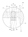
図2は、図1におけるA部の拡大図である。図2に示すように、シリンダボトム120は、シリンダチューブ110の開口を覆うボトム本体121と、ボトム本体121から軸方向に延在する環状の壁部122と、を有する。壁部122の先端部122aは、シリンダチューブ110の開口端部110aと溶接によって接合される。換言すれば、シリンダチューブ110とシリンダボトム120とは、壁部122の先端部122aとシリンダチューブ110の開口端部110aとの間に形成される接合部130を介して互いに接合される。この溶接には、プラズマ溶接及びTIG溶接を含むアーク溶接、ガス溶接、レーザー溶接、電子ビーム溶接、抵抗溶接、並びに摩擦圧接など任意の方法を用いることができる。
FIG. 2 is an enlarged view of a portion A in FIG. As shown in FIG. 2, the
また、シリンダ100は、シリンダチューブ110とシリンダボトム120との相対位置を定める位置決め部としてのバックリング140を備える。バックリング140は、シリンダチューブ110の内周面110bと壁部122の内周面122bとに対向して設けられる。
Further, the
バックリング140は、シリンダチューブ110と壁部122とが接合されていない状態では、シリンダチューブ110と壁部122とは別体に形成される。シリンダチューブ110と壁部122との接合時には、バックリング140は、シリンダチューブ110と壁部122との両方に嵌合する。これにより、接合時にシリンダチューブ110とシリンダボトム120との相対移動を防止することができ、シリンダチューブ110と壁部122とを、これらの軸心を合わせた状態で接合することができる。
The
また、シリンダチューブ110と壁部122とは、接合部130がシリンダチューブ110及び壁部122の内周にまで達するように互いに溶接される。そのため、バックリング140の外周面140aが接合部130と接合される。なお、図2に示す例では、バックリング140の外周面140aの一部のみが接合部130と接合されるが、バックリング140の外周面140aの全体が接合部130と接合されていてもよい。
Also, the
シリンダチューブ110とシリンダボトム120とが接合されたシリンダ100においては、接合部130がシリンダチューブ110の内周面110b及び壁部122の内周面122bから突出することがある。接合部130の内周にバックリング140が設けられる場合においても、接合部130がバックリング140に向かって微小に突出することがある。このような場合、接合部130に突部の根元110c,122cが形成される。根元110c,122cでは、シリンダ100が軸方向に引張荷重を受けたときに応力集中が生じやすい。
In the
シリンダ100では、根元110c,112cにおける応力を軽減するために、壁部122の内周面122bに周方向に延在する環状の溝部124が形成されている。具体的には、溝部124は、溝部124の最大内径D3が壁部122の先端部122aの内径D1、及びシリンダチューブ110の開口端部110aの内径D2よりも大きくなるように断面弓形に形成される。以下において、溝部124の最大内径D3を、単に「溝部124の内径D3」と称する。
In the
図3は、シリンダ100が軸方向に引張荷重を受けたときにシリンダボトム120からシリンダチューブ110に伝わる力の流れ(力線)を示す図であり、図2に対応して示す。図3では、力線を破線で示し、シリンダチューブ110、シリンダボトム120及び接合部130の断面を示す斜線を省略している。引張荷重は、例えば、シリンダ100内の作動油の圧力、及び油圧シリンダ1に連結される負荷によって、シリンダ100に作用する。
FIG. 3 is a diagram showing the flow of force (line of force) transmitted from the
シリンダ100が軸方向に引張荷重を受けたとき、シリンダボトム120に作用する力は、接合部130を通じてシリンダチューブ110に伝わる。このとき、力の経路は、溝部124によって狭められる。溝部124の内径D3が壁部122の先端部122aの内径D1、及びシリンダチューブ110の開口端部110aの内径D2よりも大きいので、力は、接合部130における径方向外側の領域を主に経てシリンダチューブ110に伝わる。したがって、接合部130の内周に伝わる力を低減することができ、接合部130の根元110c,122cにおける応力を軽減することができる。これにより、根元110c,122cの破損を防止することができ、シリンダ100の耐久性を向上させることができる。
When the
溝部124は、接合部130の近くに形成されるのが好ましい。これは、シリンダボトム120に作用する力は、壁部122における外周と溝部124との間を通過後、径方向内側に広がりながら接合部130を経てシリンダチューブ110に伝わるためであり、溝部124が接合部130の近くに形成されるほど、接合部130の内周面に伝わる力を低減することができるためである。
The
図2に示すように、シリンダ100では、バックリング140は、溝部124における接合部130側の縁124aと対向するように設けられる。具体的には、バックリング140の外周面140aの縁の位置は、溝部124の縁124aの位置と一致する。そのため、溝部124は、バックリング140から軸方向に間を空けることなく壁部122に形成される。したがって、溝部124を接合部130に近づけつつ軸方向におけるバックリング140の寸法を長くすることができ、シリンダチューブ110とシリンダボトム120との位置決め精度を保ちつつ接合部130の内周での応力を軽減することができる。これにより、シリンダ100を高い精度で成形することがきるとともに耐久性を向上させることができる。
As shown in FIG. 2, in the
また、バックリング140の外周面140aの縁の位置が溝部124の縁124aの位置と一致するため、バックリング140の外周面140aの全体がシリンダチューブ110の内周面110bと壁部122の内周面122bとに対向する。したがって、シリンダチューブ110と壁部122とを、これらの軸心をより高い精度で合わせた状態で接合することができる。
Further, since the position of the edge of the outer
また、溝部124の内側面には、異なる曲率半径を有する第1及び第2曲面部124b,124cが形成される。具体的には、第1曲面部124bは、溝部124の底部124dから縁124aに向かって曲面状に形成され、第2曲面部124cは、底部124dから縁124aとは反対側に曲面状に形成される。
Further, on the inner side surface of the
第1曲面部124bの曲率半径は、第2曲面部124cの曲率半径よりも小さい。そのため、溝部124の縁124aと底部124dとの間隔は、第1曲面部124bの曲率半径が第2曲面部124cの曲率半径以上である場合と比較して、小さくなる。したがって、縁124aを接合部130に近づけることなく底部124dを接合部130の近くに形成することができ、シリンダチューブ110とシリンダボトム120との位置決め精度を保ちつつ接合部130の内周での応力をより軽減することができる。これにより、シリンダ100を高い精度で成形することがきるとともに耐久性をより向上させることができる。
The radius of curvature of the first
また、シリンダ100では、バックリング140は、シリンダチューブ110とシリンダボトム120とは別体として形成されシリンダチューブ110の内周面110bと壁部122の内周面122bとに対向して設けられる。そのため、溶接時にシリンダチューブ110及びシリンダボトム120からバックリング140に熱が伝わるのを軽減することができる。したがって、温度上昇に伴うバックリング140の軟化を防止することができ、接合部130の突出を軽減することができる。これにより、接合部130における応力集中を緩和することができ、シリンダ100の耐久性をより向上させることができる。
In the
また、壁部122の内周面122bに溝部124が形成されているため、壁部122の剛性は、溝部124が形成されていない場合と比較して低い。そのため、引張荷重やシリンダ100内の作動油の圧力によりシリンダチューブ110が変形したときにシリンダチューブ110の変形に応じて壁部122を変形させることができ、接合部130の根元110c,122cに生じる応力集中を緩和することができる。
Further, since the
シリンダ100内の作動油の圧力によりシリンダチューブ110が変形するときには、壁部122におけるボトム本体121側の付け根がたわみの支点となる。溝部124は、壁部122とボトム本体121との間の隅部に形成されており、壁部122の付け根の剛性が小さい。そのため、シリンダチューブ110の変形に応じて壁部122をより容易に変形させることができる。したがって、接合部130の根元110c、122cに生じる応力集中をより緩和することができる。
When the
溝部124は、壁部122の内周面122bとボトム本体121の端面121aに渡って形成される。つまり、溝部124の内側面とボトム本体121の端面121aとが角部を間に有することなく連続する。そのため、溝部124の曲率半径を大きくすることができ、溝部124における応力集中を緩和することができる。
The
以上の第1実施形態によれば、以下の効果を奏する。 According to the first embodiment described above, the following effects can be obtained.
シリンダ100では、バックリング140が溝部124の縁124aと対向するため、溝部124を接合部130に近づけつつバックリング140を長くすることができる。したがって、接合時にはシリンダチューブ110とシリンダボトム120とを高い精度で位置決めすることができ、接合後には接合部130の内周での応力集中を軽減することができる。これにより、シリンダ100を高い精度で成形することがきるとともにシリンダ100の耐久性を向上させることができる。
In the
また、シリンダ100では、バックリング140の外周面140aの全体がシリンダチューブ110の内周面110bと壁部122の内周面122bとに対向する。したがって、接合時には、シリンダチューブ110と壁部122との軸心をより高い精度で合わせることができる。
Further, in the
また、シリンダ100では、バックリング140は、シリンダチューブ110とシリンダボトム120とは別体として形成されシリンダチューブ110の内周面110bと壁部122の内周面122bとに対向して設けられる。そのため、溶接時におけるバックリング140の軟化を防止することができ、接合部130の突出を軽減することができる。これにより、接合部130における応力集中を緩和することができ、シリンダ100の耐久性をより向上させることができる。
In the
また、第1曲面部124bの曲率半径が第2曲面部124cの曲率半径よりも小さいため、縁124aを接合部130に近づけることなく底部124dを接合部130の近くに形成することができる。したがって、接合部130の内周での応力をより軽減することができ、シリンダ100をより高い精度で成形することがきるとともに耐久性をより向上させることができる。
Further, since the radius of curvature of the first
<第2実施形態>
次に、本発明の第2実施形態に係るシリンダ200について、図4を参照して説明する。第1実施形態に係るシリンダ100と同一の構成については同一の符号を付し、その説明を省略する。また、シリンダ200を適用可能な油圧シリンダは、図1に示される油圧シリンダ1と略同じであるので、その図示を省略する。
Second Embodiment
Next, a
シリンダ200では、バックリング140は、溝部124の縁124aと重なっている。具体的には、バックリング140は、溝部124の縁124aを超えて接合部130とは反対側荷延びている。
In the
シリンダ200においても、シリンダ100と同様に、溝部124が、バックリング140から軸方向に間を空けることなく壁部122に形成される。したがって、シリンダ200を高い精度で成形することがきるとともに耐久性を向上させることができる。
Also in the
図示を省略するが、溝部124の内側面には、シリンダ100の溝部124と同様に、異なる曲率半径を有する第1及び第2曲面部が形成されていてもよい。
Although not shown, first and second curved surface portions having different radii of curvature may be formed on the inner side surface of the
<第3実施形態>
次に、本発明の第3実施形態に係るシリンダ300について、図5を参照して説明する。第1実施形態に係るシリンダ100と同一の構成については同一の符号を付し、その説明を省略する。また、シリンダ300を適用可能な油圧シリンダは、図1に示される油圧シリンダ1と略同じであるので、その図示を省略する。
Third Embodiment
Next, a
シリンダ300では、第1実施形態に係るシリンダ100の溝部124(図2参照)に代えて、溝部114がシリンダチューブ110の内周面110bに形成されている。バックリング140は、溝部114における接合部130側の縁114aと対向するように設けられる。具体的には、バックリング140の外周面140aの縁の位置は、溝部114の縁114aの位置と一致する。
In the
シリンダ300においても、溝部114は、バックリング140から軸方向に間を空けることなくシリンダチューブ110に形成される。したがって、シリンダ300を高い精度で成形することがきるとともに耐久性を向上させることができる。
Also in the
図示を省略するが、バックリング140は、溝部114の縁114aと重なっていてもよい。また。溝部114の内側面には、シリンダ100の溝部124(図2参照)と同様に、異なる曲率半径を有する第1及び第2曲面部が形成されていてもよい。加えて、壁部122の内周面122bに、溝部124(図2参照)又は溝部124(図4参照)が形成されていてもよい。
Although not shown, the buckling 140 may overlap the
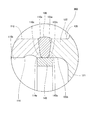
<第4実施形態>
次に、本発明の第4実施形態に係るシリンダ400について、図6を参照して説明する。第1及び第3実施形態に係るシリンダ100,300と同一の構成については同一の符号を付し、その説明を省略する。また、シリンダ400を適用可能な油圧シリンダは、図1に示される油圧シリンダ1と略同じであるので、その図示を省略する。
Fourth Embodiment
Next, a
シリンダ400では、第1及び第3実施形態に係るシリンダ100,300の溝部124,114(図2及び図5参照)に代えて、溝部114,124がシリンダチューブ110の内周面110b及びシリンダボトム120の壁部122の内周面122bにそれぞれ形成されている。バックリング140は、溝部114,124を覆うように設けられる。
In the
シリンダ400においても、溝部114,124は、バックリング140から軸方向に間を空けることなくシリンダチューブ110及びシリンダボトム120の壁部122に形成される。したがって、シリンダ400を高い精度で成形することがきるとともに耐久性を向上させることができる。
Also in the
また、バックリング140は、溝部114,124を覆うように設けられる。そのため、内周面110bのうち溝部114に対して接合部130とは反対側の領域においてもバックリング140が対向する。同様に、内周面122bのうち溝部124に対して接合部130とは反対側の領域においてもバックリング140が対向する。したがって、バックリング140の外周面140aのより広い範囲でシリンダチューブ110とシリンダボトム120とを位置決めすることができ、シリンダチューブ110と壁部122とを、これらの軸心をより高い精度で合わせた状態で接合することができる。
In addition, the buckling 140 is provided to cover the
シリンダ400では、溝部114,124が形成されているが、溝部114又は溝部124のいずれかのみが形成されていてもよい。また、溝部114,124の内側面には、シリンダ100の溝部124(図2参照)と同様に、異なる曲率半径を有する第1及び第2曲面部が形成されていてもよい。
Although the
<第5実施形態>
次に、本発明の第5実施形態に係るシリンダ500について、図7を参照して説明する。第1及び第3実施形態に係るシリンダ100,300と同一の構成については同一の符号を付し、その説明を省略する。また、シリンダ500を適用可能な油圧シリンダは、図1に示される油圧シリンダ1と略同じであるので、その図示を省略する。
Fifth Embodiment
Next, a
シリンダ500では、シリンダチューブ510は、ピストン30(図1参照)を収容するチューブ本体511と、チューブ本体511の一端から軸方向に環状に延在する環状部512と、を有する。チューブ本体511の内径がいわゆるシリンダ径に相当し、環状部512の内径は、チューブ本体511の内径よりも大きい。
In the
環状部512の先端部がシリンダチューブ510の開口端部510aであり、環状部512の先端部によってシリンダチューブ510の開口が形成される。つまり、環状部512が、シリンダボトム520の壁部522に溶接により接合される。換言すれば、シリンダチューブ510とシリンダボトム520とは、壁部522の先端部522aとシリンダチューブ510の開口端部510aとの間に形成される接合部130を介して互いに接合される。この溶接には、プラズマ溶接及びTIG溶接を含むアーク溶接、ガス溶接、レーザー溶接、電子ビーム溶接、抵抗溶接、並びに摩擦圧接など任意の方法を用いることができる。
The tip of the
バックリング140は、シリンダチューブ510の環状部512の内周面510bと壁部522の内周面522bとに対向して設けられる。そのため、シリンダチューブ510の環状部512とシリンダボトム520の壁部522とを、これらの軸心を合わせた状態で接合することができる。
The
環状部512の内周面510bには周方向に延在する環状の溝部514が形成され、壁部522の内周面522bには周方向の延在する環状の溝部524が形成される。バックリング140の外周面140aの縁の位置は、溝部514,524における接合部130側の縁514a,524aの位置と一致する。したがって、シリンダ500を高い精度で成形することがきるとともに耐久性を向上させることができる。
An
図示を省略するが、バックリング140は、溝部514,524の縁514a,524aと重なるように設けられていてもよい。また、バックリング14は、溝部514,524を覆うように設けられていてもよい。更に、溝部514,524の内側面には、シリンダ100の溝部124(図2参照)と同様に、異なる曲率半径を有する第1及び第2曲面部が形成されていてもよい。
Although not shown, the buckling 140 may be provided to overlap the
シリンダ500は、環状部512の内周面510b及び壁部522の内周面522bの両方に溝部514及び溝部524が形成された形態に限られない。環状部512の内周面510bにのみ溝部514が形成され壁部522の内周面522bには溝部524が形成されていなくてもよい。また、壁部522の内周面522bにのみ溝部524が形成され環状部512の内周面510bには溝部514が形成されていなくてもよい。
The
<第6実施形態>
次に、本発明の第6実施形態に係るシリンダ600について、図8を参照して説明する。第1実施形態に係るシリンダ100と同一の構成については同一の符号を付し、その説明を省略する。また、シリンダ600を適用可能な油圧シリンダは、図1に示される油圧シリンダ1と略同じであるので、その図示を省略する。
Sixth Embodiment
Next, a
シリンダ600では、第1実施形態に係るシリンダ100のバックリング140(図2参照)に代えて、シリンダボトム620の壁部622と一体的に形成された位置決め部としてのバック部640を備える。
The
バック部640は、シリンダチューブ110と壁部622とが接合されていない状態では、シリンダチューブ110とは別体に形成される。シリンダチューブ110と壁部622との接合時には、バック部640は、シリンダチューブ110に嵌合する。これにより、接合時にシリンダチューブ110とシリンダボトム620との相対移動を防止することができ、シリンダチューブ110と壁部622とを、これらの軸心を合わせた状態で接合することができる。
The
バック部640が壁部622と一体的に形成されるので、バック部640をシリンダチューブ110に嵌合する際に、壁部622に対してバック部640が移動するのを防止することができる。したがって、シリンダチューブ110と壁部622とを容易に接合することができ、シリンダ600を容易に製造することができる。
Since the
接合部130は、シリンダチューブ110の内周にまで達している。そのため、バック部640の外周面640aが接合部130と接合される。なお、図8に示す例では、バック部640の外周面640aの一部のみが接合部130と接合されるが、バック部640の外周面640aの全体が接合部130と接合されていてもよい。
The
シリンダチューブ110の内周面110bには周方向に延在する環状の溝部114が形成される。バック部640の外周面640aの縁の位置は、溝部114における接合部130側の縁114aの位置と一致する。そのため、溝部114は、バック部640から軸方向に間を空けることなくシリンダチューブ110に形成される。したがって、軸方向におけるバック部640の寸法を短くすることなく溝部114を接合部130の近くに形成することができる。これにより、シリンダ600を高い精度で成形することがきるとともに耐久性を向上させることができる。
An
壁部622の内周面622bには、環状の溝部624が形成される。溝部624の内径D3は、シリンダチューブ110の開口端部110aの内径D2よりも大きい。そのため、溝部624によっても、接合部130の内周に伝わる力を低減することができ、接合部130の根元110cにおける応力を軽減することができる。これにより、根元110cの破損を防止することができ、シリンダ600の耐久性を向上させることができる。
An
図示を省略するが、バック部640は、溝部114の縁114aと重なるように設けられていてもよい。また、バック部640は、溝部114を覆うように設けられていてもよい。更に、溝部114の内側面には、シリンダ100の溝部124(図2参照)と同様に、異なる曲率半径を有する第1及び第2曲面部が形成されていてもよい。
Although not shown, the
また、バック部640は、壁部622に変えて、シリンダチューブ110と一体に形成されていてもよい。この場合には、シリンダボトム620に代えて図2に示すシリンダボトム120によりシリンダチューブ110の開口が閉塞され、溝部124の縁124aの位置は、シリンダチューブ110と一体に形成されるバック部640の外周面640aの縁の位置と一致する。
Also, the
以下、本発明の実施形態の構成、作用、及び効果をまとめて説明する。 Hereinafter, the configuration, operation, and effects of the embodiment of the present invention will be collectively described.
シリンダ100,200,300,400,500,600は、シリンダチューブ110,510と、環状の壁部122,522,622を有し、壁部122,522,622とシリンダチューブ110,510とが互いに接合されてシリンダチューブ110,510の開口を閉塞するシリンダボトム120,520,620と、シリンダチューブ110,510及び壁部122,522,622の内周面110b,122b,510b,522b,622bに対向して設けられ、シリンダチューブ110,510とシリンダボトム120,520,620との相対位置を定めるバックリング140又はバック部640と、内周面110b,122b,510b,522b,622bに形成され、周方向に延びる溝部114,124,514,524と、を備え、バックリング140又はバック部640は、溝部114,124,514,524の縁114a,124a,514a,524aと対向するように設けられる。
The
この構成では、溝部114,124,514,524を壁部122,522,622とシリンダチューブ110,510との接合部130に近づけつつバックリング140又はバック部640を長くすることができる。したがって、接合時にはシリンダチューブ110,510とシリンダボトム120,520,620とを高い精度で位置決めすることができ、接合後には接合部130の内周での応力を軽減することができる。これにより、シリンダ100,200,300,400,500,600の成形精度及び耐久性を向上させることができる。
In this configuration, it is possible to lengthen the buckling 140 or the
また、シリンダ100,200,300,400,500では、バックリング140は、シリンダチューブ110,510及びシリンダボトム120,520とは別体として形成され、シリンダチューブ110,510及び壁部122,522の両方の内周面110b,122b,510b,522bに対向して設けられる。
Further, in the
この構成では、シリンダチューブ110,510及びシリンダボトム120,520からバックリング140への熱の伝達が軽減される。したがって、接合時におけるバックリング140の軟化を防止することができ、壁部122,522とシリンダチューブ110,510との接合部130の突出を軽減することができる。これにより、接合部130における応力集中を緩和することができ、シリンダ100,200,300,400,500の耐久性を向上させることができる。
In this configuration, heat transfer from the
また、シリンダ100,300、500,600では、バックリング140又はバック部640は、その縁の位置が溝部114,124,514,524の縁の位置と一致するように設けられる。
Further, in the
この構成では、バックリング140又はバック部640の外周面140a,640aの全体がシリンダチューブ110,510及び壁部122,522の内周面110b,510b,122b,522bと対向する。したがって、シリンダチューブ110,510と壁部122,522とを、これらの軸心をより高い精度で合わせた状態で接合することができる。
In this configuration, the entire outer
また、シリンダ400は、バックリング140は、溝部114,124を覆うように設けられる。
In addition, the
この構成では、内周面110b,122bのうち溝部114,124に対して接合部130とは反対側の領域においてもバックリング140が対向する。したがって、シリンダチューブ110とシリンダボトム120との位置決め精度をより向上させることができる。
In this configuration, the buckling 140 also faces in the region of the inner
また、シリンダ100では、溝部124の内側面は、溝の底部124dから接合部130に向かって曲面状に形成される第1曲面部124bと、溝の底部124dから接合部130とは反対側に向かって曲面状に形成される第2曲面部124cと、を有し、第1曲面部124bの曲率半径は、第2曲面部124cの曲率半径よりも小さい。
Further, in the
この構成では、溝部124の縁124aを接合部130に近づけることなく溝部124の底部124dを接合部130に近づけることができる。したがって、接合部130の内周での応力をより軽減することができ、シリンダ100の耐久性をより向上させることができる。
In this configuration, the bottom 124 d of the
本実施形態は、シリンダに作動油が給排されることによって伸縮作動する油圧シリンダ1に係る。シリンダは、シリンダ100,200,300,400,500,600である。
The present embodiment relates to a hydraulic cylinder 1 that is extended and contracted by supplying and discharging hydraulic oil to the cylinder. The cylinders are the
この構成では、シリンダが前述のシリンダ100,200,300,400,500,600であるので、シリンダは高い耐久性を有する。したがって、油圧シリンダ1の耐久性を向上させることができる。
In this configuration, since the cylinders are the
以上、本発明の実施形態について説明したが、上記実施形態は本発明の適用例の一部を示したに過ぎず、本発明の技術的範囲を上記実施形態の具体的構成に限定する趣旨ではない。 As mentioned above, although the embodiment of the present invention was described, the above-mentioned embodiment showed only a part of application example of the present invention, and in the meaning of limiting the technical scope of the present invention to the concrete composition of the above-mentioned embodiment. Absent.
(1)本実施形態では、溝部114,124,514,524,624は、周方向に全周に形成されるが、溝部114,124,514,524,624は、周方向における一部に形成されていてもよい。
(1) In the present embodiment, the
(2)溝部114,124,514,524,624の断面は弓形以外の形状、例えば三角形、四角形等の形状であってもよい。溝部114,124,514,524,624の断面は弓形であることが好ましく、この場合には、溝部114,124,514,524,624における応力集中を緩和することができる。
(2) The cross section of the
(3)上記実施形態では、耐圧機器として、油圧シリンダ1に用いられるシリンダについて説明した。耐圧機器は、これに限らず、液体や気体を保管するためのボンベなどの圧力容器でもよい。 (3) In the said embodiment, the cylinder used for the hydraulic cylinder 1 was demonstrated as a pressure | voltage resistant apparatus. The pressure resistant apparatus is not limited to this, and may be a pressure vessel such as a cylinder for storing liquid or gas.
1・・・油圧シリンダ(流体圧シリンダ)、100,200,300,400,500,600・・・シリンダ(耐圧機器)、110,510・・・シリンダチューブ(筒状の本体部)、110b、510b・・・内周面、114,514・・・溝部、114a,514a・・・縁、120,520,620・・・シリンダボトム(蓋部)、122,522,622・・・壁部、124,524・・・溝部、124a,524a・・・縁、124b・・・第1曲面部、124c・・・第2曲面部、124d・・・底部、130・・・接合部、140・・・バックリング(位置決め部)、640・・・バック部(位置決め部)
1: Hydraulic cylinder (fluid pressure cylinder), 100, 200, 300, 400, 500, 600: cylinder (pressure-resistant device), 110, 510: cylinder tube (cylindrical main body), 110b,
Claims (8)
筒状の本体部と、
環状の壁部を有し、前記壁部と前記本体部とが互いに接合されて前記本体部の開口を閉塞する蓋部と、
前記本体部及び前記壁部の少なくとも一方の内周面に対向して設けられ、前記本体部と前記蓋部との相対位置を定める位置決め部と、
前記本体部及び前記壁部の前記少なくとも一方の内周面に形成され、周方向に延びる溝部と、を備え、
前記位置決め部は、前記溝部の縁と対向するように設けられると共に、前記本体部及び前記蓋部とは別体として形成され前記本体部及び前記壁部の両方の内周面に対向して設けられることを特徴とする
耐圧機器。 Pressure resistant equipment,
A tubular main body,
A lid portion having an annular wall portion, wherein the wall portion and the main body portion are joined to each other to close the opening of the main body portion;
A positioning portion provided opposite to an inner peripheral surface of at least one of the main body portion and the wall portion to determine a relative position between the main body portion and the lid portion;
And a groove extending in the circumferential direction and formed on the inner peripheral surface of the at least one of the main body and the wall.
The positioning portion is provided to face the edge of the groove, and is formed separately from the main body and the lid, and provided to face the inner circumferential surfaces of both the main body and the wall. Pressure-resistant equipment characterized in that
前記位置決め部は、その縁の位置が前記溝部の縁の位置と一致するように設けられることを特徴とする
耐圧機器。 A pressure resistant device according to claim 1 , wherein
The said positioning part is provided so that the position of the edge may correspond with the position of the edge of the said groove part, The pressure | voltage resistant apparatus characterized by the above-mentioned.
前記位置決め部は、前記溝部を覆うように設けられることを特徴とする
耐圧機器。 A pressure resistant device according to claim 1 , wherein
The said positioning part is provided so that the said groove part may be covered, The pressure | voltage resistant apparatus characterized by the above-mentioned.
前記溝部の内側面は、前記溝の底部から前記壁部と前記本体部との接合部に向かって曲面状に形成される第1曲面部と、前記溝の底部から前記接合部とは反対側に向かって曲面状に形成される第2曲面部と、を有し、
前記第1曲面部の曲率半径は、前記第2曲面部の曲率半径よりも小さいことを特徴とする
耐圧機器。 It is a pressure-resistant apparatus of any one of Claim 1 to 3 , Comprising:
The inner surface of the groove is a first curved surface portion formed in a curved shape from the bottom of the groove toward the joint between the wall and the main body, and the side opposite to the joint from the bottom of the groove And a second curved surface portion formed in a curved shape toward the
The pressure-resistant apparatus characterized in that the radius of curvature of the first curved surface portion is smaller than the radius of curvature of the second curved surface portion.
筒状の本体部と、A tubular main body,
環状の壁部を有し、前記壁部と前記本体部とが互いに接合されて前記本体部の開口を閉塞する蓋部と、A lid portion having an annular wall portion, wherein the wall portion and the main body portion are joined to each other to close the opening of the main body portion;
前記本体部及び前記壁部の少なくとも一方の内周面に対向して設けられ、前記本体部と前記蓋部との相対位置を定める位置決め部と、A positioning portion provided opposite to an inner peripheral surface of at least one of the main body portion and the wall portion to determine a relative position between the main body portion and the lid portion;
前記本体部及び前記壁部の前記少なくとも一方の内周面に形成され、周方向に延びる溝部と、を備え、And a groove extending in the circumferential direction and formed on the inner peripheral surface of the at least one of the main body and the wall.
前記位置決め部は、前記溝部の縁と対向しかつ前記位置決め部の縁の位置が前記溝部の縁の位置と一致するように設けられることを特徴とするThe positioning portion is provided so as to face the edge of the groove portion and the position of the edge of the positioning portion coincides with the position of the edge of the groove portion.
耐圧機器。Pressure resistant equipment.
筒状の本体部と、A tubular main body,
環状の壁部を有し、前記壁部と前記本体部とが互いに接合されて前記本体部の開口を閉塞する蓋部と、A lid portion having an annular wall portion, wherein the wall portion and the main body portion are joined to each other to close the opening of the main body portion;
前記本体部及び前記壁部の少なくとも一方の内周面に対向して設けられ、前記本体部と前記蓋部との相対位置を定める位置決め部と、A positioning portion provided opposite to an inner peripheral surface of at least one of the main body portion and the wall portion to determine a relative position between the main body portion and the lid portion;
前記本体部及び前記壁部の前記少なくとも一方の内周面に形成され、周方向に延びる溝部と、を備え、And a groove extending in the circumferential direction and formed on the inner peripheral surface of the at least one of the main body and the wall.
前記位置決め部は、前記溝部の縁と対向しかつ前記溝部を覆うように設けられることを特徴とするThe positioning portion is provided to face the edge of the groove and to cover the groove.
耐圧機器。Pressure resistant equipment.
筒状の本体部と、A tubular main body,
環状の壁部を有し、前記壁部と前記本体部とが互いに接合されて前記本体部の開口を閉塞する蓋部と、A lid portion having an annular wall portion, wherein the wall portion and the main body portion are joined to each other to close the opening of the main body portion;
前記本体部及び前記壁部の少なくとも一方の内周面に対向して設けられ、前記本体部と前記蓋部との相対位置を定める位置決め部と、A positioning portion provided opposite to an inner peripheral surface of at least one of the main body portion and the wall portion to determine a relative position between the main body portion and the lid portion;
前記本体部及び前記壁部の前記少なくとも一方の内周面に形成され、周方向に延びる溝部と、を備え、And a groove extending in the circumferential direction and formed on the inner peripheral surface of the at least one of the main body and the wall.
前記位置決め部は、前記溝部の縁と対向して設けられ、The positioning portion is provided to face the edge of the groove,
前記溝部の内側面は、前記溝の底部から前記壁部と前記本体部との接合部に向かって曲面状に形成される第1曲面部と、前記溝の底部から前記接合部とは反対側に向かって曲面状に形成される第2曲面部と、を有し、The inner surface of the groove is a first curved surface portion formed in a curved shape from the bottom of the groove toward the joint between the wall and the main body, and the side opposite to the joint from the bottom of the groove And a second curved surface portion formed in a curved shape toward the
前記第1曲面部の曲率半径は、前記第2曲面部の曲率半径よりも小さいことを特徴とするThe radius of curvature of the first curved surface portion is smaller than the radius of curvature of the second curved surface portion.
耐圧機器。Pressure resistant equipment.
前記シリンダは、請求項1から7のいずれか1項に記載の耐圧機器であることを特徴とする
流体圧シリンダ。 A fluid pressure cylinder that is extended and contracted by supplying and discharging a working fluid to the cylinder, comprising:
The fluid pressure cylinder characterized in that the cylinder is the pressure resistant device according to any one of claims 1 to 7 .
Priority Applications (5)
| Application Number | Priority Date | Filing Date | Title |
|---|---|---|---|
| JP2017194856A JP6530800B2 (en) | 2017-10-05 | 2017-10-05 | Pressure resistant equipment and fluid pressure cylinder |
| PCT/JP2018/036085 WO2019069797A1 (en) | 2017-10-05 | 2018-09-27 | Pressure resistance instrument and fluid pressure cylinder |
| US16/642,746 US11174881B2 (en) | 2017-10-05 | 2018-09-27 | Pressure resistant device and fluid pressure cylinder |
| CN201880058617.5A CN111051709B (en) | 2017-10-05 | 2018-09-27 | Pressure-resistant equipment and fluid pressure cylinder |
| DE112018004418.1T DE112018004418T5 (en) | 2017-10-05 | 2018-09-27 | Pressure-resistant device and fluid pressure cylinder |
Applications Claiming Priority (1)
| Application Number | Priority Date | Filing Date | Title |
|---|---|---|---|
| JP2017194856A JP6530800B2 (en) | 2017-10-05 | 2017-10-05 | Pressure resistant equipment and fluid pressure cylinder |
Publications (3)
| Publication Number | Publication Date |
|---|---|
| JP2019063853A JP2019063853A (en) | 2019-04-25 |
| JP2019063853A5 JP2019063853A5 (en) | 2019-06-06 |
| JP6530800B2 true JP6530800B2 (en) | 2019-06-12 |
Family
ID=65995040
Family Applications (1)
| Application Number | Title | Priority Date | Filing Date |
|---|---|---|---|
| JP2017194856A Active JP6530800B2 (en) | 2017-10-05 | 2017-10-05 | Pressure resistant equipment and fluid pressure cylinder |
Country Status (5)
| Country | Link |
|---|---|
| US (1) | US11174881B2 (en) |
| JP (1) | JP6530800B2 (en) |
| CN (1) | CN111051709B (en) |
| DE (1) | DE112018004418T5 (en) |
| WO (1) | WO2019069797A1 (en) |
Families Citing this family (3)
| Publication number | Priority date | Publication date | Assignee | Title |
|---|---|---|---|---|
| JP2021143748A (en) * | 2020-03-13 | 2021-09-24 | Kyb株式会社 | Pressure-resistant device and fluid pressure cylinder |
| JP7530217B2 (en) | 2020-06-10 | 2024-08-07 | カヤバ株式会社 | Pressure-resistant equipment and fluid pressure cylinders |
| DE102021001107A1 (en) * | 2021-03-02 | 2022-09-08 | Bümach Engineering International B.V. | Working cylinder and method for its manufacture |
Family Cites Families (18)
| Publication number | Priority date | Publication date | Assignee | Title |
|---|---|---|---|---|
| US3559540A (en) * | 1968-08-06 | 1971-02-02 | Arnold C Sheldon | Hydraulic actuator |
| US4324171A (en) * | 1978-06-16 | 1982-04-13 | Clark Equipment Company | Fluid device and method for making |
| JPS591493U (en) * | 1982-06-29 | 1984-01-07 | 日立建機株式会社 | Welded structure of cylinder |
| JPS6075703U (en) * | 1983-10-31 | 1985-05-27 | カヤバ工業株式会社 | hydraulic cylinder |
| US5651303A (en) * | 1994-11-14 | 1997-07-29 | Polygon Company | Fluid cylinder end cap assembly |
| JP4083596B2 (en) * | 2003-02-26 | 2008-04-30 | ユニシア ジェーケーシー ステアリングシステム株式会社 | Power steering device |
| NL2001389C2 (en) * | 2008-03-19 | 2009-09-22 | Actuant Corp | Hydraulic cylinder and method for manufacturing thereof. |
| CN201730889U (en) * | 2009-10-28 | 2011-02-02 | 海克力斯(上海)液压机械有限公司 | High-pressure hydraulic cylinder head welding structure device |
| DE202012009001U1 (en) * | 2012-09-19 | 2014-01-15 | Bümach Engineering International B.V. | working cylinder |
| JP5981877B2 (en) * | 2013-04-26 | 2016-08-31 | 川崎重工業株式会社 | Piston and hydraulic rotating machine provided in hydraulic rotating machine |
| JP6098880B2 (en) * | 2013-05-07 | 2017-03-22 | Smc株式会社 | Fluid pressure cylinder |
| DE102013008351B9 (en) * | 2013-05-16 | 2014-10-02 | Schwing Gmbh | Component with at least two parts welded together |
| CN104632759A (en) * | 2015-01-23 | 2015-05-20 | 山东隆源液压科技有限公司 | Accessory quick-change oil cylinder |
| KR20180132692A (en) | 2016-04-18 | 2018-12-12 | 케이와이비 가부시키가이샤 | Pressure-resistant devices and fluid pressure cylinders |
| JP6774210B2 (en) * | 2016-04-18 | 2020-10-21 | Kyb株式会社 | Pressure-resistant equipment and fluid pressure cylinder |
| JP2017194087A (en) * | 2016-04-18 | 2017-10-26 | Kyb株式会社 | Pressure resistant apparatus and fluid pressure cylinder |
| JP2017194856A (en) | 2016-04-21 | 2017-10-26 | 株式会社リコー | Information processing device, information processing method, and information processing program |
| US10697479B1 (en) * | 2017-06-09 | 2020-06-30 | JARP Industries, Inc. | Pressure vessel and method of welding a pressure vessel sidewall and end cap together |
-
2017
- 2017-10-05 JP JP2017194856A patent/JP6530800B2/en active Active
-
2018
- 2018-09-27 CN CN201880058617.5A patent/CN111051709B/en active Active
- 2018-09-27 WO PCT/JP2018/036085 patent/WO2019069797A1/en active Application Filing
- 2018-09-27 US US16/642,746 patent/US11174881B2/en active Active
- 2018-09-27 DE DE112018004418.1T patent/DE112018004418T5/en active Pending
Also Published As
| Publication number | Publication date |
|---|---|
| CN111051709B (en) | 2021-12-21 |
| JP2019063853A (en) | 2019-04-25 |
| WO2019069797A1 (en) | 2019-04-11 |
| DE112018004418T5 (en) | 2020-05-20 |
| US20210079937A1 (en) | 2021-03-18 |
| CN111051709A (en) | 2020-04-21 |
| US11174881B2 (en) | 2021-11-16 |
Similar Documents
| Publication | Publication Date | Title |
|---|---|---|
| JP6530800B2 (en) | Pressure resistant equipment and fluid pressure cylinder | |
| JP2017194087A (en) | Pressure resistant apparatus and fluid pressure cylinder | |
| JP4253644B2 (en) | Manufacturing method of piston for internal combustion engine | |
| US20110081239A1 (en) | Fabricated static vane ring | |
| JP2005127388A (en) | High pressure container and its manufacturing method | |
| US10907662B2 (en) | Bonded body, fluid pressure cylinder, and manufacturing method of bonded body | |
| US20220397129A1 (en) | Working cylinder | |
| JP6774210B2 (en) | Pressure-resistant equipment and fluid pressure cylinder | |
| WO2017183561A1 (en) | Pressure-resistant equipment and fluid pressure cylinder | |
| JP2016188701A (en) | Hula seal | |
| JP7365403B2 (en) | bellows type accumulator | |
| JP7530217B2 (en) | Pressure-resistant equipment and fluid pressure cylinders | |
| WO2021106932A1 (en) | Power element and expansion valve using same | |
| JP6803271B2 (en) | accumulator | |
| CN110418900B (en) | Pressure accumulator | |
| JP6924122B2 (en) | Manufacturing method of pressure resistant equipment, fluid pressure cylinder, and pressure resistant equipment | |
| WO2021182184A1 (en) | Pressure resistant instrument and fluid pressure cylinder | |
| WO2016098619A1 (en) | Pressure resistant device | |
| ES2951978T3 (en) | Sealing component, in particular for sealing a vapor chamber against the environment or two vapor chambers with different pressures, and use of said component | |
| JP5564119B2 (en) | Solenoid valve having a core sleeve and method for welding the core sleeve | |
| JP2007078069A (en) | Resin pipe fitting structure and assembling method for resin pipe fitting | |
| JP5178552B2 (en) | Pressure vessel, accumulator and pressure vessel lid manufacturing method | |
| KR102709269B1 (en) | Electric machine and its manufacturing method | |
| JP6997190B2 (en) | Pipe mechanism and furnace | |
| JPWO2020255524A5 (en) | Joint structure and high-pressure fuel supply pump using this |
Legal Events
| Date | Code | Title | Description |
|---|---|---|---|
| A521 | Request for written amendment filed |
Free format text: JAPANESE INTERMEDIATE CODE: A523 Effective date: 20190401 |
|
| A621 | Written request for application examination |
Free format text: JAPANESE INTERMEDIATE CODE: A621 Effective date: 20190401 |
|
| A871 | Explanation of circumstances concerning accelerated examination |
Free format text: JAPANESE INTERMEDIATE CODE: A871 Effective date: 20190401 |
|
| A975 | Report on accelerated examination |
Free format text: JAPANESE INTERMEDIATE CODE: A971005 Effective date: 20190404 |
|
| TRDD | Decision of grant or rejection written | ||
| A01 | Written decision to grant a patent or to grant a registration (utility model) |
Free format text: JAPANESE INTERMEDIATE CODE: A01 Effective date: 20190423 |
|
| A61 | First payment of annual fees (during grant procedure) |
Free format text: JAPANESE INTERMEDIATE CODE: A61 Effective date: 20190517 |
|
| R151 | Written notification of patent or utility model registration |
Ref document number: 6530800 Country of ref document: JP Free format text: JAPANESE INTERMEDIATE CODE: R151 |
|
| S533 | Written request for registration of change of name |
Free format text: JAPANESE INTERMEDIATE CODE: R313533 |
|
| R350 | Written notification of registration of transfer |
Free format text: JAPANESE INTERMEDIATE CODE: R350 |