JP5178552B2 - Pressure vessel, accumulator and pressure vessel lid manufacturing method - Google Patents
Pressure vessel, accumulator and pressure vessel lid manufacturing method Download PDFInfo
- Publication number
- JP5178552B2 JP5178552B2 JP2009014555A JP2009014555A JP5178552B2 JP 5178552 B2 JP5178552 B2 JP 5178552B2 JP 2009014555 A JP2009014555 A JP 2009014555A JP 2009014555 A JP2009014555 A JP 2009014555A JP 5178552 B2 JP5178552 B2 JP 5178552B2
- Authority
- JP
- Japan
- Prior art keywords
- pressure vessel
- outer shell
- shell member
- lid body
- fiber direction
- Prior art date
- Legal status (The legal status is an assumption and is not a legal conclusion. Google has not performed a legal analysis and makes no representation as to the accuracy of the status listed.)
- Active
Links
Images


Landscapes
- Supply Devices, Intensifiers, Converters, And Telemotors (AREA)
- Diaphragms And Bellows (AREA)
- Pressure Vessels And Lids Thereof (AREA)
Description
本発明は、自動車や産業機械等に用いられる圧力容器、アキュムレータ及び圧力容器蓋体の製造方法に関し、特に高圧ガスの漏れを最小限に抑えたものに関する。 The present invention relates to a pressure vessel, an accumulator, and a method for manufacturing a pressure vessel lid used for automobiles, industrial machines, and the like, and particularly relates to a method for minimizing leakage of high-pressure gas.
油圧制御装置の油圧回路やショックアブソーバ等にアキュムレータが用いられている。金属ベローズ式のアキュムレータは、一般に、圧力容器の内部がベローズによってガス室と油室とに区画され、油室内に流入する油の圧力変動をベローズの伸縮を伴うガス室内のガスの膨縮作用によって緩衝する構成となっている(例えば、特許文献1〜3参照)。アキュムレータは、油圧回路を流れる油に生じる脈動を効果的に抑制するための装置として、例えば自動車や産業機械に広く用いられており、蓄圧用としても広く用いられている。
上述したアキュムレータでは、次のような問題があった。すなわち、アキュムレータを構成する外殻部材や蓋体は金属材を通常押出成型により形成しているため、組織が繊維状となっている。組織の繊維方向が内部から外部にかけて形成され、金属材に不純物が含まれていると、アキュムレータに高い圧力でガスが収容されたとき、ガスが繊維に沿って少しずつ抜けてしまうことがある。このため、アキュムレータとしての所期の機能が発揮できないという場合があった。 The accumulator described above has the following problems. That is, since the outer shell member and the lid constituting the accumulator are formed by extrusion molding a metal material, the structure is fibrous. If the fiber direction of the tissue is formed from the inside to the outside and impurities are contained in the metal material, when the gas is stored in the accumulator at a high pressure, the gas may gradually escape along the fiber. For this reason, the intended function as an accumulator may not be exhibited.
そこで本発明は、圧力容器内のガス室における高圧ガスの抜けを防止できる圧力容器、アキュムレータ及び圧力容器蓋体の製造方法を提供することを目的としている。 Accordingly, an object of the present invention is to provide a pressure vessel, an accumulator, and a method of manufacturing a pressure vessel lid that can prevent the escape of high-pressure gas in a gas chamber in the pressure vessel.
前記課題を解決し目的を達成するために、本発明の圧力容器、アキュムレータ及び圧力容器蓋体の製造方法は次のように構成されている。 In order to solve the above-described problems and achieve the object, the pressure vessel, accumulator and pressure vessel lid manufacturing method of the present invention are configured as follows.
筒状の外殻部材と、押出成形により軸方向に沿う繊維方向が形成された棒状の基部の一部を、据込により径方向に延ばし、上記繊維方向が上記軸方向に対し交差する方向に傾けられ、切削されて形成され、上記外殻部材の開口端の内壁部にその側壁部を当接させて接合部を形成して閉塞する蓋体とを備え、上記蓋体は、上記切削において、上記繊維方向が上記蓋体の内外方向に対し交差する方向となるよう切削されることを特徴とする。 A cylindrical outer shell member and a part of a rod-like base portion in which a fiber direction along the axial direction is formed by extrusion are radially extended by upsetting, and the fiber direction intersects the axial direction. And a lid that is formed by being inclined and cut, and contacting the side wall with the inner wall of the open end of the outer shell member to form a joint and closing the lid . The fiber direction is cut so as to intersect with the inside / outside direction of the lid .
有底筒状の外殻部材、及び、押出成形により軸方向に沿う繊維方向が形成された棒状の基部の一部を、据込により径方向に延ばし、上記繊維方向が上記軸方向に対し交差する方向に傾けられ、切削されて形成され、上記外殻部材の開口部を閉塞し、且つ、液体を前記外殻部材内部へと流出入可能な流入孔を有する蓋体を具備する圧力容器と、この圧力容器内壁面に沿って伸縮自在に形成された金属ベローズ、及び、金属ベローズに設けられ、前記圧力容器内壁面に沿って前記金属ベローズに追従して移動する仕切板を有し、これら金属ベローズ及び仕切板により前記圧力容器内を、前記液体を流出入可能な液室及びガスを封入可能な気室に仕切るベローズ機構とを備え、上記蓋体は、上記切削において、上記繊維方向が上記蓋体の内外方向に対し交差する方向となるよう切削されることを特徴とする。 A bottomed cylindrical outer shell member and a part of a rod-like base portion in which the fiber direction along the axial direction is formed by extrusion are extended in the radial direction by upsetting, and the fiber direction intersects the axial direction. A pressure vessel comprising a lid body that is formed by being inclined and cut , closes the opening of the outer shell member, and has an inflow hole through which liquid can flow into and out of the outer shell member. A metal bellows formed to be stretchable along the inner wall surface of the pressure vessel, and a partition plate that is provided on the metal bellows and moves following the metal bellows along the inner wall surface of the pressure vessel. A bellows mechanism that partitions the inside of the pressure vessel into a liquid chamber capable of flowing in and out of the liquid and a gas chamber capable of enclosing gas by a metal bellows and a partition plate, and the lid body has a fiber direction in the cutting. Inward and outward direction of the lid Characterized in that it is cut to be a direction intersecting.
筒状の外殻部材の開口端の内壁部にその側壁部を当接させて閉塞する圧力容器蓋体の製造方法において、押出成型により繊維方向を軸方向とした棒状の基部を形成する工程と、前記基部の一部を据込により径方向に延ばし、その繊維方向を軸方向に対し交差する方向に傾ける工程と、その繊維方向が前記蓋体の内外方向に対し交差する方向となるように前記基部を切削する工程とを備えていることを特徴とする。 In the method of manufacturing a pressure vessel lid that closes by contacting the side wall with the inner wall of the opening end of the cylindrical outer shell member, a step of forming a rod-like base with the fiber direction as the axial direction by extrusion molding; A step of extending a part of the base portion in the radial direction by upsetting, and inclining the fiber direction in a direction intersecting the axial direction, so that the fiber direction intersects the inner and outer directions of the lid And a step of cutting the base portion.
本発明によれば、圧力容器内のガス室における高圧ガスの抜けを防止することが可能となる。 According to the present invention, it is possible to prevent escape of high-pressure gas in the gas chamber in the pressure vessel.
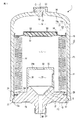
図1は本発明の一実施の形態に係るアキュムレータ1の構成を示す縦断面図である。なお、図1中Gはガス室(気室)、Lは油室(液室)を、Sは圧力容器の溶接部(接合部)をそれぞれ示している。
FIG. 1 is a longitudinal sectional view showing a configuration of an
図1に示すように、アキュムレータ1は、圧力容器10と、圧力容器10に収容されたベローズ機構50とを備えている。このようなアキュムレータ1は、例えば車体のブレーキ用油圧回路上の配管に後述するポート部22を介して接続されている。
As shown in FIG. 1, the
圧力容器10は、有底筒状の鋼材で形成された外殻部材11と、外殻部材11が有する開口部12と結合する蓋体13とを備えている。また、圧力容器10は、例えば、外殻部材11と蓋体13とを溶接部(接合部)Sで溶接させることで構成されている。圧力容器10は、その内部に、外殻部材11とベローズ機構50と蓋体13とにより形成されたガス室Gと、蓋体13とベローズ機構50とにより形成された油室Lとを有している。
The
外殻部材11は、管部15と底部16とが例えば深絞りにより一体成形されており、深絞りの成形後、焼鈍等の熱処理を行なう場合がある。このとき、組織の繊維方向F1は軸方向Cとほぼ一致しており、圧力容器10の内外方向に対して交差している。
In the
外殻部材11は、管部15の内壁面15a及び底部16の内面16aにより内壁面17が形成されている。この内壁面17とベローズ機構50と蓋体13によりガス室Gを形成する。なお、開口部12には、蓋体13が挿入されるとともに、溶接部Sで蓋体13が溶接される。
In the
底部16には、円形状の貫通孔18が形成されている。この貫通孔18はガス封入栓19により気密に閉塞されている。さらに、貫通孔18の外部にはカバー20が取り付けられている。
A circular through
蓋体13は、円盤状に形成された蓋体本体21と、この蓋体本体21の軸心上に設けられたポート部22と、蓋体本体21のポート部22が設けられている第1面23と、第1面23と相対する第2面24とを備えている。また、蓋体13は、蓋体本体21の軸心上、かつ、第2面24側に、例えば溶接により接合された円筒部材26を備えている。
The
蓋体13は、図2〜図6に示すような工程で製造されている。すなわち、図2に示すように押出成型により繊維方向F2を軸方向Cとした棒状の基部Kが形成される。次に、図3〜図5に示すように、基部Kの一部を据込により径方向に徐々に延ばし、その繊維方向F2を軸方向Cに対し交差する方向に傾ける。そして、基部Kを図6中Pで示すように、その繊維方向F2が蓋体13の内外方向に対し交差する方向となるように切削する。このように蓋体13を製造することで、組織の繊維方向F2が圧力容器10の内外方向に対して交差する方向に設定されることとなる。
The
蓋体本体21は、少なくともその径が、開口部12に挿入することで第2面24側が外殻部材11の内側に位置し、第1面23が外殻部材11の外部に露出する位置となる内径を有している。また、蓋体本体21の側面部27の第2面24側には、樹脂材料等により形成されたリング状の遮断シール28を挿入するシール溝29が設けられている。
The
詳しく述べると、蓋体本体21は、第1面23側が管部15の内周径よりも大径に形成され、第2面24側が管部15の内周径よりも小径に形成されている。また、蓋体本体21の側面のシール溝29よりも第1面23側に設けられ、溶接時に溶解することで、外殻部材11の曲面部12aと溶接される溶接部Sが設けられている。
More specifically, the
ポート部22は、この内部に、油室Lと作動油の流出入を行なう通油孔30が設けられている。
The
円筒部材26は、内部に空洞部31が形成されており、通油孔30と連続している。また、円筒部材26の端面部32には、空洞部31と油室Lとを連続させる連通孔33が設けられている。また、円筒部材26は、ベローズ機構50と対向する端面26aが、所定の精度を有する表面粗さに形成されている。すなわち、円筒部材26の端面26aは、後述するシール部材53が当接することで、油室Lを円筒部材26の空洞部31から液封可能な表面粗さを有している。
The
ベローズ機構50は、筒状に形成され開口端の一方が、蓋体本体21の第2面24に配置された金属ベローズ51と、この金属ベローズ51の開口端の他方に取り付けられた円板状のベローズキャップ(仕切板)52とを備えている。また、ベローズ機構50は、ベローズキャップ52に設けられたシール部材53と、ベローズキャップ52の外周部に取り付けられたガイド54とを備えている。
The
金属ベローズ51は、第2面24と当接する一端部が、蓋体本体21の第2面24と溶接により接合されている。この金属ベローズ51と蓋体本体21との接合点は、油室L及びガス室G間の液(気)密性を有している。
One end of the metal bellows 51 that contacts the
ベローズキャップ52は、ベローズキャップ52の軸心上に設けられ、油室L側からその内部にシール部材53が嵌合される有底円筒の凹部56を有している。また、ベローズキャップ52は、蓋体13と対向する面(油室L側の面)に、金属ベローズ51の他端部が溶接により、油室L及びガス室G間の液(気)密性を有して接合されている。
The bellows cap 52 is provided on the axial center of the bellows cap 52 and has a bottomed
ガイド54は、金属ベローズ51の伸縮にあわせベローズキャップ52が移動する際に内壁面17をスムースに摺動可能な摺動部材で形成されている。なお、ガイド54は、内壁面17をスムースに摺動可能に形成されているだけであり、ガス室Gと、内壁面17及び金属ベローズ51の空間とは連通している。
The
このように構成されたアキュムレータ1では、油圧回路の圧力が上昇することで、ポート部22の通油孔30、円筒部材26内の空洞部31及び連通孔33を介して油室L内に油圧回路内の作動油が流入する。この作動油の流入により、油室L内に圧力が印加され、アキュムレータ1は、油圧回路内の圧力を蓄圧するとともに、油圧回路内の脈動を緩衝することとなる。
In the
このときの油室Lの油圧がガス室Gのガス圧を超えると、図1に示すように、金属ベローズ51は伸張しガス室G内のガスが収縮する。このガス室G内のガスの収縮により、所定の位置で、作動油とガスとの釣り合いが取れることとなる。 When the oil pressure in the oil chamber L at this time exceeds the gas pressure in the gas chamber G, the metal bellows 51 expands and the gas in the gas chamber G contracts as shown in FIG. Due to the contraction of the gas in the gas chamber G, the hydraulic oil and the gas are balanced at a predetermined position.
このとき、ガス室Gの圧力が上昇するが、外殻部材11及び蓋体13の繊維方向F1,F2が内外方向に対し交差する方向に設定されているため、繊維方向F1,F2に沿って高い圧力のガスが抜けることがなく、内部のガス量を安定的に保持することができる。したがって、アキュムレータとしての所期の機能を維持することができる。
At this time, although the pressure in the gas chamber G increases, the fiber directions F1 and F2 of the
次に、油圧回路内の圧力が増圧すると、油室L内の圧力が増圧し、さらにガスを収縮させ、金属ベローズ51が伸張する。このとき、油圧回路内の使用圧力でガス圧が調整されており、金属ベローズ51は、ガイド54が管部15の内壁面15aを摺動する範囲のみを伸縮することとなる。
Next, when the pressure in the hydraulic circuit is increased, the pressure in the oil chamber L is increased, the gas is further contracted, and the metal bellows 51 is expanded. At this time, the gas pressure is adjusted by the working pressure in the hydraulic circuit, and the metal bellows 51 expands and contracts only in the range in which the
次に、油圧回路内の圧力が低下すると、油室L内の作動油の油圧がガス室G内のガス圧を下回り、金属ベローズ51は収縮し、これによりガス室G内のガスが膨張する。このとき、油室L内の油圧が所定の圧力より低い場合には、シール部材53のシール面54と円筒部材26の端面26aとが当接する位置まで、金属ベローズ51が収縮し、ベローズキャップ52が移動する。
Next, when the pressure in the hydraulic circuit decreases, the hydraulic pressure of the hydraulic oil in the oil chamber L falls below the gas pressure in the gas chamber G, and the metal bellows 51 contracts, whereby the gas in the gas chamber G expands. . At this time, if the hydraulic pressure in the oil chamber L is lower than a predetermined pressure, the metal bellows 51 contracts to a position where the
このシール面54と端面26aとが当接することで、円筒部材26の連通孔33の周囲の端面26aをシール部材53によりシールすることとなる。
When the
このように構成されたアキュムレータ1によれば、油圧回路から作動油が油室Lに流入し、ガス室G内のガス圧が高くなっても、組織の繊維方向F1,F2が圧力容器10の内外方向に対して交差する方向に設定されているので、ガスが外殻部材11や蓋体13から抜けることがなく、所期の機能を維持することができる。
According to the
なお、本発明は前記実施の形態に限定されるものではなく、本発明の要旨を逸脱しない範囲で種々変形実施可能であるのは勿論である。
以下に、本願出願の当初の特許請求の範囲に記載された発明を付記する。
[1]筒状の外殻部材と、この外殻部材の開口端の内壁部にその側壁部を当接させて接合部を形成して閉塞する蓋体とを備え、上記外殻部材又は蓋体は、その内外方向と繊維方向とが交差した金属材で形成されていることを特徴とする圧力容器。
[2]有底筒状の外殻部材、及び、この外殻部材の開口部を閉塞し、且つ、液体を前記外殻部材内部へと流出入可能な流入孔を有する蓋体を具備する圧力容器と、この圧力容器内壁面に沿って伸縮自在に形成された金属ベローズ、及び、金属ベローズに設けられ、前記圧力容器内壁面に沿って前記金属ベローズに追従して移動する仕切板を有し、これら金属ベローズ及び仕切板により前記圧力容器内を、前記液体を流出入可能な液室及びガスを封入可能な気室に仕切るベローズ機構とを備え、上記外殻部材又は蓋体は、その内外方向と繊維方向とが交差した金属材で形成されていることを特徴とするアキュムレータ。
[3]筒状の外殻部材の開口端の内壁部にその側壁部を当接させて閉塞する圧力容器蓋体の製造方法において、押出成型により繊維方向を軸方向とした棒状の基部を形成する工程と、前記基部の一部を据込により径方向に延ばし、その繊維方向を軸方向に対し交差する方向に傾ける工程と、その繊維方向が前記蓋体の内外方向に対し交差する方向となるように前記基部を切削する工程とを備えていることを特徴とする圧力容器蓋体の製造方法。
Note that the present invention is not limited to the above-described embodiment, and various modifications can be made without departing from the scope of the present invention .
Hereinafter, the invention described in the scope of claims of the present application will be appended.
[1] A cylindrical outer shell member, and a lid body that closes the inner wall portion at the opening end of the outer shell member by contacting the side wall portion to form a joint portion and closing the outer shell member or the lid. The pressure vessel characterized in that the body is formed of a metal material in which the inside and outside directions and the fiber direction intersect.
[2] Pressure including a bottomed cylindrical outer shell member and a lid body that closes an opening of the outer shell member and has an inflow hole through which liquid can flow into and out of the outer shell member. A container, a metal bellows formed to be stretchable along the inner wall surface of the pressure vessel, and a partition plate that is provided on the metal bellows and moves following the metal bellows along the inner wall surface of the pressure vessel. A bellows mechanism for partitioning the inside of the pressure vessel into a liquid chamber capable of flowing in and out of the liquid and an air chamber capable of enclosing gas by the metal bellows and the partition plate, and the outer shell member or the lid body An accumulator characterized in that the accumulator is formed of a metal material in which the direction and the fiber direction intersect.
[3] In a method of manufacturing a pressure vessel lid that closes by contacting an inner wall portion of an opening end of a cylindrical outer shell member with a side wall portion thereof, a rod-like base portion having a fiber direction as an axial direction is formed by extrusion molding. A step of extending a part of the base portion in the radial direction by upsetting and inclining the fiber direction in a direction intersecting the axial direction, and a direction in which the fiber direction intersects the inner and outer directions of the lid body And a step of cutting the base so as to become a pressure vessel lid manufacturing method.
1…アキュムレータ、10…圧力容器、11…外殻部材、13…蓋体、50…ベローズ機構。
DESCRIPTION OF
Claims (3)
押出成形により軸方向に沿う繊維方向が形成された棒状の基部の一部を、据込により径方向に延ばし、上記繊維方向が上記軸方向に対し交差する方向に傾けられ、切削されて形成され、上記外殻部材の開口端の内壁部にその側壁部を当接させて接合部を形成して閉塞する蓋体とを備え、
上記蓋体は、上記切削において、上記繊維方向が上記蓋体の内外方向に対し交差する方向となるよう切削されることを特徴とする圧力容器。 A cylindrical outer shell member;
A part of the rod-like base portion in which the fiber direction along the axial direction is formed by extrusion is radially extended by upsetting, and the fiber direction is inclined and cut in a direction intersecting the axial direction. , and a lid for closing and forming a joint by contacting the side wall portion on the inner wall portion of the open end of the outer shell member,
The pressure vessel according to claim 1, wherein the lid body is cut in the cutting so that the fiber direction intersects the inner and outer directions of the lid body .
この圧力容器内壁面に沿って伸縮自在に形成された金属ベローズ、及び、金属ベローズに設けられ、前記圧力容器内壁面に沿って前記金属ベローズに追従して移動する仕切板を有し、これら金属ベローズ及び仕切板により前記圧力容器内を、前記液体を流出入可能な液室及びガスを封入可能な気室に仕切るベローズ機構とを備え、
上記蓋体は、上記切削において、上記繊維方向が上記蓋体の内外方向に対し交差する方向となるよう切削されることを特徴とするアキュムレータ。 A bottomed cylindrical outer shell member and a part of a rod-like base portion in which the fiber direction along the axial direction is formed by extrusion are extended in the radial direction by upsetting, and the fiber direction intersects the axial direction. A pressure vessel comprising a lid body that is formed by being inclined and cut , closes the opening of the outer shell member, and has an inflow hole through which liquid can flow into and out of the outer shell member. ,
A metal bellows formed to be stretchable along the inner wall surface of the pressure vessel, and a partition plate that is provided on the metal bellows and moves following the metal bellows along the inner wall surface of the pressure vessel. A bellows mechanism that partitions the inside of the pressure vessel into a liquid chamber capable of flowing in and out of the liquid and an air chamber capable of enclosing gas by a bellows and a partition plate;
The accumulator is characterized in that, in the cutting, the lid body is cut so that the fiber direction is in a direction intersecting the inner and outer directions of the lid body .
押出成型により繊維方向を軸方向とした棒状の基部を形成する工程と、
前記基部の一部を据込により径方向に延ばし、その繊維方向を軸方向に対し交差する方向に傾ける工程と、
その繊維方向が前記蓋体の内外方向に対し交差する方向となるように前記基部を切削する工程とを備えていることを特徴とする圧力容器蓋体の製造方法。 In the manufacturing method of the pressure vessel lid that closes the inner wall portion of the open end of the cylindrical outer shell member by contacting the side wall portion thereof,
Forming a rod-like base with the fiber direction as an axial direction by extrusion;
Extending a part of the base in the radial direction by upsetting and inclining the fiber direction in a direction intersecting the axial direction;
And a step of cutting the base so that the fiber direction intersects the inner and outer directions of the lid body.
Priority Applications (1)
| Application Number | Priority Date | Filing Date | Title |
|---|---|---|---|
| JP2009014555A JP5178552B2 (en) | 2009-01-26 | 2009-01-26 | Pressure vessel, accumulator and pressure vessel lid manufacturing method |
Applications Claiming Priority (1)
| Application Number | Priority Date | Filing Date | Title |
|---|---|---|---|
| JP2009014555A JP5178552B2 (en) | 2009-01-26 | 2009-01-26 | Pressure vessel, accumulator and pressure vessel lid manufacturing method |
Publications (2)
| Publication Number | Publication Date |
|---|---|
| JP2010169235A JP2010169235A (en) | 2010-08-05 |
| JP5178552B2 true JP5178552B2 (en) | 2013-04-10 |
Family
ID=42701573
Family Applications (1)
| Application Number | Title | Priority Date | Filing Date |
|---|---|---|---|
| JP2009014555A Active JP5178552B2 (en) | 2009-01-26 | 2009-01-26 | Pressure vessel, accumulator and pressure vessel lid manufacturing method |
Country Status (1)
| Country | Link |
|---|---|
| JP (1) | JP5178552B2 (en) |
Families Citing this family (1)
| Publication number | Priority date | Publication date | Assignee | Title |
|---|---|---|---|---|
| CN103867502B (en) * | 2012-12-12 | 2017-06-06 | 日本发条株式会社 | accumulator |
Family Cites Families (3)
| Publication number | Priority date | Publication date | Assignee | Title |
|---|---|---|---|---|
| US5139132A (en) * | 1991-09-09 | 1992-08-18 | Ball Corporation | Orientation apparatus and method for disk shaped parts |
| JPH1177215A (en) * | 1997-06-26 | 1999-03-23 | Japan Steel Works Ltd:The | Manufacturing method of vacuum chamber |
| JP4550402B2 (en) * | 2003-12-02 | 2010-09-22 | 日本発條株式会社 | Accumulator and method of manufacturing accumulator |
-
2009
- 2009-01-26 JP JP2009014555A patent/JP5178552B2/en active Active
Also Published As
| Publication number | Publication date |
|---|---|
| JP2010169235A (en) | 2010-08-05 |
Similar Documents
| Publication | Publication Date | Title |
|---|---|---|
| US10273979B2 (en) | Accumulator | |
| US20180259028A1 (en) | Shock absorber | |
| JP6420602B2 (en) | Shock absorber | |
| JP2010174985A (en) | Gas filling method for accumulator | |
| JP2006226343A (en) | Accumulator and shock absorber | |
| US8496030B2 (en) | Hydraulic accumulator, especially pulsation damper | |
| US10330170B2 (en) | Shock absorber | |
| JP5178552B2 (en) | Pressure vessel, accumulator and pressure vessel lid manufacturing method | |
| JP5694612B1 (en) | Pressure shock absorber | |
| JP5711264B2 (en) | Guide device for metal bellows | |
| CN116635644B (en) | Vibration damper with external control valve | |
| JP6803271B2 (en) | accumulator | |
| JP2011214633A (en) | Cylinder device | |
| WO2018143066A1 (en) | Accumulator | |
| JP3889370B2 (en) | accumulator | |
| JP2017053482A (en) | Locking system for actuating cylinder and actuating cylinder | |
| JP5811047B2 (en) | Metal bellows type accumulator | |
| WO2017086012A1 (en) | Bump stopper and buffer | |
| JP4402449B2 (en) | Hydraulic shock absorber | |
| JPWO2009116155A1 (en) | damper | |
| US9689405B1 (en) | Hydraulic accumulator | |
| EP3252318B1 (en) | Hydraulic accumulator | |
| JP3148351U (en) | accumulator | |
| JP2009138882A (en) | Metal bellows type accumulator | |
| JP5159659B2 (en) | Accumulator manufacturing equipment |
Legal Events
| Date | Code | Title | Description |
|---|---|---|---|
| A621 | Written request for application examination |
Free format text: JAPANESE INTERMEDIATE CODE: A621 Effective date: 20110801 |
|
| A977 | Report on retrieval |
Free format text: JAPANESE INTERMEDIATE CODE: A971007 Effective date: 20120831 |
|
| A131 | Notification of reasons for refusal |
Free format text: JAPANESE INTERMEDIATE CODE: A131 Effective date: 20120904 |
|
| A521 | Request for written amendment filed |
Free format text: JAPANESE INTERMEDIATE CODE: A523 Effective date: 20121102 |
|
| TRDD | Decision of grant or rejection written | ||
| A01 | Written decision to grant a patent or to grant a registration (utility model) |
Free format text: JAPANESE INTERMEDIATE CODE: A01 Effective date: 20121211 |
|
| A61 | First payment of annual fees (during grant procedure) |
Free format text: JAPANESE INTERMEDIATE CODE: A61 Effective date: 20130108 |
|
| R150 | Certificate of patent or registration of utility model |
Ref document number: 5178552 Country of ref document: JP Free format text: JAPANESE INTERMEDIATE CODE: R150 |
|
| R250 | Receipt of annual fees |
Free format text: JAPANESE INTERMEDIATE CODE: R250 |
|
| R250 | Receipt of annual fees |
Free format text: JAPANESE INTERMEDIATE CODE: R250 |
|
| R250 | Receipt of annual fees |
Free format text: JAPANESE INTERMEDIATE CODE: R250 |
|
| R250 | Receipt of annual fees |
Free format text: JAPANESE INTERMEDIATE CODE: R250 |
|
| R250 | Receipt of annual fees |
Free format text: JAPANESE INTERMEDIATE CODE: R250 |
|
| R250 | Receipt of annual fees |
Free format text: JAPANESE INTERMEDIATE CODE: R250 |
|
| R250 | Receipt of annual fees |
Free format text: JAPANESE INTERMEDIATE CODE: R250 |
|
| R250 | Receipt of annual fees |
Free format text: JAPANESE INTERMEDIATE CODE: R250 |
|
| R250 | Receipt of annual fees |
Free format text: JAPANESE INTERMEDIATE CODE: R250 |
|
| R250 | Receipt of annual fees |
Free format text: JAPANESE INTERMEDIATE CODE: R250 |
|
| R250 | Receipt of annual fees |
Free format text: JAPANESE INTERMEDIATE CODE: R250 |