JP6529280B2 - Exhaust gas temperature control device and exhaust gas temperature control device - Google Patents
Exhaust gas temperature control device and exhaust gas temperature control device Download PDFInfo
- Publication number
- JP6529280B2 JP6529280B2 JP2015036509A JP2015036509A JP6529280B2 JP 6529280 B2 JP6529280 B2 JP 6529280B2 JP 2015036509 A JP2015036509 A JP 2015036509A JP 2015036509 A JP2015036509 A JP 2015036509A JP 6529280 B2 JP6529280 B2 JP 6529280B2
- Authority
- JP
- Japan
- Prior art keywords
- exhaust gas
- temperature
- temperature control
- control device
- heat storage
- Prior art date
- Legal status (The legal status is an assumption and is not a legal conclusion. Google has not performed a legal analysis and makes no representation as to the accuracy of the status listed.)
- Expired - Fee Related
Links
Images


Classifications
-
- F—MECHANICAL ENGINEERING; LIGHTING; HEATING; WEAPONS; BLASTING
- F01—MACHINES OR ENGINES IN GENERAL; ENGINE PLANTS IN GENERAL; STEAM ENGINES
- F01N—GAS-FLOW SILENCERS OR EXHAUST APPARATUS FOR MACHINES OR ENGINES IN GENERAL; GAS-FLOW SILENCERS OR EXHAUST APPARATUS FOR INTERNAL COMBUSTION ENGINES
- F01N9/00—Electrical control of exhaust gas treating apparatus
- F01N9/002—Electrical control of exhaust gas treating apparatus of filter regeneration, e.g. detection of clogging
-
- F—MECHANICAL ENGINEERING; LIGHTING; HEATING; WEAPONS; BLASTING
- F01—MACHINES OR ENGINES IN GENERAL; ENGINE PLANTS IN GENERAL; STEAM ENGINES
- F01N—GAS-FLOW SILENCERS OR EXHAUST APPARATUS FOR MACHINES OR ENGINES IN GENERAL; GAS-FLOW SILENCERS OR EXHAUST APPARATUS FOR INTERNAL COMBUSTION ENGINES
- F01N3/00—Exhaust or silencing apparatus having means for purifying, rendering innocuous, or otherwise treating exhaust
- F01N3/02—Exhaust or silencing apparatus having means for purifying, rendering innocuous, or otherwise treating exhaust for cooling, or for removing solid constituents of, exhaust
- F01N3/021—Exhaust or silencing apparatus having means for purifying, rendering innocuous, or otherwise treating exhaust for cooling, or for removing solid constituents of, exhaust by means of filters
- F01N3/023—Exhaust or silencing apparatus having means for purifying, rendering innocuous, or otherwise treating exhaust for cooling, or for removing solid constituents of, exhaust by means of filters using means for regenerating the filters, e.g. by burning trapped particles
- F01N3/0234—Exhaust or silencing apparatus having means for purifying, rendering innocuous, or otherwise treating exhaust for cooling, or for removing solid constituents of, exhaust by means of filters using means for regenerating the filters, e.g. by burning trapped particles using heat exchange means in the exhaust line
-
- F—MECHANICAL ENGINEERING; LIGHTING; HEATING; WEAPONS; BLASTING
- F01—MACHINES OR ENGINES IN GENERAL; ENGINE PLANTS IN GENERAL; STEAM ENGINES
- F01N—GAS-FLOW SILENCERS OR EXHAUST APPARATUS FOR MACHINES OR ENGINES IN GENERAL; GAS-FLOW SILENCERS OR EXHAUST APPARATUS FOR INTERNAL COMBUSTION ENGINES
- F01N3/00—Exhaust or silencing apparatus having means for purifying, rendering innocuous, or otherwise treating exhaust
- F01N3/02—Exhaust or silencing apparatus having means for purifying, rendering innocuous, or otherwise treating exhaust for cooling, or for removing solid constituents of, exhaust
- F01N3/021—Exhaust or silencing apparatus having means for purifying, rendering innocuous, or otherwise treating exhaust for cooling, or for removing solid constituents of, exhaust by means of filters
- F01N3/023—Exhaust or silencing apparatus having means for purifying, rendering innocuous, or otherwise treating exhaust for cooling, or for removing solid constituents of, exhaust by means of filters using means for regenerating the filters, e.g. by burning trapped particles
- F01N3/027—Exhaust or silencing apparatus having means for purifying, rendering innocuous, or otherwise treating exhaust for cooling, or for removing solid constituents of, exhaust by means of filters using means for regenerating the filters, e.g. by burning trapped particles using electric or magnetic heating means
-
- F—MECHANICAL ENGINEERING; LIGHTING; HEATING; WEAPONS; BLASTING
- F01—MACHINES OR ENGINES IN GENERAL; ENGINE PLANTS IN GENERAL; STEAM ENGINES
- F01N—GAS-FLOW SILENCERS OR EXHAUST APPARATUS FOR MACHINES OR ENGINES IN GENERAL; GAS-FLOW SILENCERS OR EXHAUST APPARATUS FOR INTERNAL COMBUSTION ENGINES
- F01N3/00—Exhaust or silencing apparatus having means for purifying, rendering innocuous, or otherwise treating exhaust
- F01N3/08—Exhaust or silencing apparatus having means for purifying, rendering innocuous, or otherwise treating exhaust for rendering innocuous
- F01N3/10—Exhaust or silencing apparatus having means for purifying, rendering innocuous, or otherwise treating exhaust for rendering innocuous by thermal or catalytic conversion of noxious components of exhaust
- F01N3/18—Exhaust or silencing apparatus having means for purifying, rendering innocuous, or otherwise treating exhaust for rendering innocuous by thermal or catalytic conversion of noxious components of exhaust characterised by methods of operation; Control
- F01N3/20—Exhaust or silencing apparatus having means for purifying, rendering innocuous, or otherwise treating exhaust for rendering innocuous by thermal or catalytic conversion of noxious components of exhaust characterised by methods of operation; Control specially adapted for catalytic conversion ; Methods of operation or control of catalytic converters
- F01N3/2066—Selective catalytic reduction [SCR]
-
- F—MECHANICAL ENGINEERING; LIGHTING; HEATING; WEAPONS; BLASTING
- F01—MACHINES OR ENGINES IN GENERAL; ENGINE PLANTS IN GENERAL; STEAM ENGINES
- F01N—GAS-FLOW SILENCERS OR EXHAUST APPARATUS FOR MACHINES OR ENGINES IN GENERAL; GAS-FLOW SILENCERS OR EXHAUST APPARATUS FOR INTERNAL COMBUSTION ENGINES
- F01N9/00—Electrical control of exhaust gas treating apparatus
-
- F—MECHANICAL ENGINEERING; LIGHTING; HEATING; WEAPONS; BLASTING
- F01—MACHINES OR ENGINES IN GENERAL; ENGINE PLANTS IN GENERAL; STEAM ENGINES
- F01N—GAS-FLOW SILENCERS OR EXHAUST APPARATUS FOR MACHINES OR ENGINES IN GENERAL; GAS-FLOW SILENCERS OR EXHAUST APPARATUS FOR INTERNAL COMBUSTION ENGINES
- F01N2240/00—Combination or association of two or more different exhaust treating devices, or of at least one such device with an auxiliary device, not covered by indexing codes F01N2230/00 or F01N2250/00, one of the devices being
- F01N2240/10—Combination or association of two or more different exhaust treating devices, or of at least one such device with an auxiliary device, not covered by indexing codes F01N2230/00 or F01N2250/00, one of the devices being a heat accumulator
-
- F—MECHANICAL ENGINEERING; LIGHTING; HEATING; WEAPONS; BLASTING
- F01—MACHINES OR ENGINES IN GENERAL; ENGINE PLANTS IN GENERAL; STEAM ENGINES
- F01N—GAS-FLOW SILENCERS OR EXHAUST APPARATUS FOR MACHINES OR ENGINES IN GENERAL; GAS-FLOW SILENCERS OR EXHAUST APPARATUS FOR INTERNAL COMBUSTION ENGINES
- F01N2900/00—Details of electrical control or of the monitoring of the exhaust gas treating apparatus
- F01N2900/06—Parameters used for exhaust control or diagnosing
- F01N2900/14—Parameters used for exhaust control or diagnosing said parameters being related to the exhaust gas
- F01N2900/1404—Exhaust gas temperature
-
- Y—GENERAL TAGGING OF NEW TECHNOLOGICAL DEVELOPMENTS; GENERAL TAGGING OF CROSS-SECTIONAL TECHNOLOGIES SPANNING OVER SEVERAL SECTIONS OF THE IPC; TECHNICAL SUBJECTS COVERED BY FORMER USPC CROSS-REFERENCE ART COLLECTIONS [XRACs] AND DIGESTS
- Y02—TECHNOLOGIES OR APPLICATIONS FOR MITIGATION OR ADAPTATION AGAINST CLIMATE CHANGE
- Y02A—TECHNOLOGIES FOR ADAPTATION TO CLIMATE CHANGE
- Y02A50/00—TECHNOLOGIES FOR ADAPTATION TO CLIMATE CHANGE in human health protection, e.g. against extreme weather
- Y02A50/20—Air quality improvement or preservation, e.g. vehicle emission control or emission reduction by using catalytic converters
-
- Y—GENERAL TAGGING OF NEW TECHNOLOGICAL DEVELOPMENTS; GENERAL TAGGING OF CROSS-SECTIONAL TECHNOLOGIES SPANNING OVER SEVERAL SECTIONS OF THE IPC; TECHNICAL SUBJECTS COVERED BY FORMER USPC CROSS-REFERENCE ART COLLECTIONS [XRACs] AND DIGESTS
- Y02—TECHNOLOGIES OR APPLICATIONS FOR MITIGATION OR ADAPTATION AGAINST CLIMATE CHANGE
- Y02T—CLIMATE CHANGE MITIGATION TECHNOLOGIES RELATED TO TRANSPORTATION
- Y02T10/00—Road transport of goods or passengers
- Y02T10/10—Internal combustion engine [ICE] based vehicles
- Y02T10/12—Improving ICE efficiencies
-
- Y—GENERAL TAGGING OF NEW TECHNOLOGICAL DEVELOPMENTS; GENERAL TAGGING OF CROSS-SECTIONAL TECHNOLOGIES SPANNING OVER SEVERAL SECTIONS OF THE IPC; TECHNICAL SUBJECTS COVERED BY FORMER USPC CROSS-REFERENCE ART COLLECTIONS [XRACs] AND DIGESTS
- Y02—TECHNOLOGIES OR APPLICATIONS FOR MITIGATION OR ADAPTATION AGAINST CLIMATE CHANGE
- Y02T—CLIMATE CHANGE MITIGATION TECHNOLOGIES RELATED TO TRANSPORTATION
- Y02T10/00—Road transport of goods or passengers
- Y02T10/10—Internal combustion engine [ICE] based vehicles
- Y02T10/40—Engine management systems
Description
本発明は内燃機関の排気管路に配置される、排気ガスの温度を制御する排気ガス温度制御装置および排気ガスの温度調整装置に関する。 The present invention relates to an exhaust gas temperature control device for controlling the temperature of exhaust gas and an exhaust gas temperature control device, which are disposed in an exhaust pipe line of an internal combustion engine.
近年における内燃機関の排出ガス(排気ガス)成分に関する規制に対応するために、内燃機関の排気管経路には種々の排気ガス浄化装置が配置されている。これら排気ガス浄化装置は、触媒や尿素水といった化学物質とNOxやPM(粒子状物質:Particulate Matter)といった排気ガス成分との間における化学反応によって排気ガス成分を浄化しており、化学物質は最適な浄化性能を発揮するための温度域を有する。一方で、内燃機関における燃焼効率の向上に伴い排気ガス温度は低下傾向にある。そこで、排気管経路に蓄熱体を含む経路および蓄熱体を迂回するための経路を設け、排気ガスの温度を調整することにより、後段の選択還元触媒の床温をNOx浄化率が相対的に高くなる温度域に制御する技術が提案されている(たとえば、特許文献1)。 In order to comply with recent regulations concerning the exhaust gas (exhaust gas) component of the internal combustion engine, various exhaust gas purification devices are disposed in the exhaust pipe path of the internal combustion engine. These exhaust gas purifiers purify exhaust gas components by chemical reaction between chemical substances such as catalyst and urea water and exhaust gas components such as NOx and PM (particulate matter), and the chemical substances are optimum Have a temperature range for achieving good purification performance. On the other hand, with the improvement of combustion efficiency in an internal combustion engine, the temperature of exhaust gas tends to decrease. Therefore, by providing the path including the heat storage and the path for bypassing the heat storage in the exhaust pipe route and adjusting the temperature of the exhaust gas, the bed temperature of the subsequent selective reduction catalyst is relatively high at the NOx purification rate There has been proposed a technique for controlling the temperature range as described above (for example, Patent Document 1).
しかしながら、蓄熱体のみを用いる技術では、蓄熱体自体の温度が低い場合、排気ガスを蓄熱体と接触させることで却って排気ガス温度を低下させてしまう、あるいは、排気ガスの温度を所望の温度まで昇温できないという問題がある。また、加熱装置を用いて排気ガス温度を昇温させる場合には、加熱装置に対する電力の供給が車両の走行負荷となり、車両の燃費消費性能を低下させるという問題がある。 However, in the technology using only the heat storage body, when the temperature of the heat storage body itself is low, the exhaust gas temperature is reduced by bringing the exhaust gas into contact with the heat storage body, or the temperature of the exhaust gas is increased to a desired temperature There is a problem that the temperature can not be raised. In addition, when the temperature of the exhaust gas is raised using the heating device, the power supply to the heating device causes a load on the vehicle to run, which causes a problem of reducing the fuel consumption performance of the vehicle.
したがって、内燃機関から排出される排気ガスの温度に依存せず、車両全体におけるエネルギー効率の低下を抑制しつつ、排気ガス温度を浄化装置の作動温度域に調整することが望まれている。 Therefore, it is desired to adjust the exhaust gas temperature to the operating temperature range of the purification device while suppressing the decrease in energy efficiency in the entire vehicle independently of the temperature of the exhaust gas discharged from the internal combustion engine.
本発明は、上述の課題を解決するためになされたものであり、以下の態様として実現することが可能である。 The present invention has been made to solve the above-described problems, and can be realized as the following aspects.
第1の態様は、内燃機関の排気管路に配置されている排気ガス浄化装置の前段における排気ガス温度を調整する排気ガス温度制御装置を提供する。第1の態様に係る排気ガス温度制御装置は、熱を蓄熱または放熱可能な蓄熱体と、前記蓄熱体に熱を蓄熱させるための加熱部材と、前記内燃機関を搭載する車両の運転状態に応じて、前記蓄熱体に熱を蓄熱または前記蓄熱体から熱を放熱させて前記排気ガス温度制御装置から排出される排気ガスの温度を制御する温度制御部と、を備える。 A first aspect provides an exhaust gas temperature control device that adjusts the temperature of the exhaust gas at the front stage of an exhaust gas purification device disposed in an exhaust pipe line of an internal combustion engine. The exhaust gas temperature control device according to the first aspect includes a heat storage body capable of storing or releasing heat, a heating member for storing heat in the heat storage body, and an operating state of a vehicle equipped with the internal combustion engine. And a temperature control unit for storing heat in the heat storage body or releasing heat from the heat storage body to control the temperature of the exhaust gas discharged from the exhaust gas temperature control device.
第1の態様に係る排気ガス温度制御装置によれば、内燃機関から排出される排気ガスの温度に依存せず、車両全体におけるエネルギー効率の低下を抑制しつつ、排気ガス温度を浄化装置の作動温度域に調整することができる。 According to the exhaust gas temperature control device according to the first aspect, the exhaust gas temperature does not depend on the temperature of the exhaust gas discharged from the internal combustion engine, and the exhaust gas temperature is activated while the reduction of the energy efficiency is suppressed. It can be adjusted to the temperature range.
第1の態様に係る排気ガス温度制御装置において、前記加熱部材は、前記車両の運転状態に応じて得られる回生電力によって発熱しても良い。この場合には、車両全体におけるエネルギー効率を低下させることなく、加熱部材を発熱させて排気ガス温度を浄化装置の作動温度域に調整することができる。 In the exhaust gas temperature control device according to the first aspect, the heating member may generate heat by regenerative power obtained according to the driving state of the vehicle. In this case, the exhaust gas temperature can be adjusted to the operating temperature range of the purification device by causing the heating member to generate heat without reducing the energy efficiency of the entire vehicle.
第1の態様に係る排気ガス温度制御装置において、さらに、前記蓄熱体を内包し、前記排気ガスの流路を構成する第1の流路部と、前記第1の流路部とは異なる、前記排気ガスの流路を構成する第2の流路部と、前記排気ガスの流路を前記第1の流路部と前記第2流路部の少なくともいずれか一方に切り替える切替部とを備え、前記温度制御部は、さらに、前記切替部を制御することによって、前記蓄熱体に熱を蓄熱または前記蓄熱体から熱を放熱させても良い。この場合には、排気ガスの流路を、蓄熱体を介する流路と、蓄熱体を介さない流路とに切り替え、蓄熱体に熱を蓄熱または蓄熱体から熱を放熱させることができる。 In the exhaust gas temperature control device according to the first aspect, further, a first flow path portion that includes the heat storage body and that configures a flow path of the exhaust gas is different from the first flow path portion. A second flow path portion constituting the flow path of the exhaust gas, and a switching portion for switching the flow path of the exhaust gas to at least one of the first flow path portion and the second flow path portion The temperature control unit may further store heat in the heat storage body or release heat from the heat storage body by controlling the switching unit. In this case, the flow path of the exhaust gas can be switched to the flow path via the heat storage body and the flow path not via the heat storage body, and the heat storage body can store heat or release heat from the heat storage body.
第1の態様に係る排気ガス温度制御装置において、前記温度制御部は、前記排気ガス温度が第1の所定温度以上であり、前記蓄熱体の温度が前記第1の所定温度よりも低い第2の所定温度未満の場合に、または、前記排気ガス温度が前記第1の所定温度よりも低い第3の所定温度未満であり、前記蓄熱体の温度が前記第2の所定温度および前記第3の所定温度よりも高い第4の所定温度以上の場合に、前記第1の流路部に前記排気ガスを導くよう前記切替部を切り替えても良い。この場合には、排気ガスによる蓄熱体の蓄熱、蓄熱体による排気ガスの昇温を行い、排気ガス温度制御装置から排出される排気ガス温度を制御することができる。 In the exhaust gas temperature control device according to the first aspect, the temperature control unit is configured such that the exhaust gas temperature is equal to or higher than a first predetermined temperature, and the temperature of the heat storage body is lower than the first predetermined temperature. Or the exhaust gas temperature is less than a third predetermined temperature lower than the first predetermined temperature, and the temperature of the heat storage body is equal to the second predetermined temperature and the third predetermined temperature. The switching unit may be switched so as to lead the exhaust gas to the first flow passage when the temperature is equal to or higher than a fourth predetermined temperature which is higher than the predetermined temperature. In this case, the heat storage of the heat storage body by the exhaust gas and the temperature rise of the exhaust gas by the heat storage body can be performed to control the temperature of the exhaust gas discharged from the exhaust gas temperature control device.
第1の態様に係る排気ガス温度制御装置において、前記温度制御部は、前記排気ガス温度が前記第1の所定温度未満かつ前記第3の所定温度以上の場合、前記第2の流路部に前記排気ガスを導くよう前記切替部を切り替えても良い。この場合には、蓄熱体を介することなく排気ガス温度制御装置から排出される排気ガス温度を所定の温度範囲の温度に制御することができる。 In the exhaust gas temperature control device according to the first aspect, in the case where the temperature of the exhaust gas is lower than the first predetermined temperature and equal to or higher than the third predetermined temperature, the temperature control unit may The switching unit may be switched to lead the exhaust gas. In this case, the temperature of the exhaust gas discharged from the exhaust gas temperature control device can be controlled to a temperature within a predetermined temperature range without the heat storage medium.
第1の態様に係る排気ガス温度制御装置において、前記温度制御部は、前記車両の運転状態が減速状態にある場合、低温始動状態にある場合、または、定常状態にある場合には、前記第2の流路部に前記排気ガスを導くように前記切替部を切り替えても良い。この場合には、蓄熱体を介することなく排気ガスを排出することが可能となる。 In the exhaust gas temperature control device according to the first aspect, the temperature control unit is configured to reduce the operating condition of the vehicle when in a decelerating condition, in a low temperature starting condition, or in a steady condition. The switching unit may be switched so as to lead the exhaust gas to the second flow passage. In this case, the exhaust gas can be discharged without intervention of the heat storage body.
第1の態様に係る排気ガス温度制御装置において、前記温度制御部は、前記車両の運転状態が減速状態にある場合、得られた回生電力を前記加熱部材に供給しても良い。この場合には、車両全体におけるエネルギー効率を低下させることなく、加熱部材を発熱させて蓄熱体に蓄熱し、蓄熱した熱を用いて必要な時に排気ガス温度を浄化装置の作動温度域に調整することができる。 In the exhaust gas temperature control device according to the first aspect, the temperature control unit may supply the obtained regenerative electric power to the heating member when the driving state of the vehicle is in a decelerating state. In this case, without reducing the energy efficiency of the entire vehicle, the heating member generates heat to store heat in the heat storage body, and the stored heat is used to adjust the exhaust gas temperature to the operating temperature range of the purification device when necessary. be able to.
第1の態様に係る排気ガス温度制御装置において、前記温度制御部は、前記車両の運転状態が加速状態にある場合、所定の負荷よりも高い高負荷状態にある場合には、前記第1の流路部に前記排気ガスを導くように前記切替部を切り替えても良い。この場合には、排気ガス温度を蓄熱体によって低下させることができる。 In the exhaust gas temperature control device according to the first aspect, when the driving state of the vehicle is in the acceleration state, the temperature control unit is configured to perform the first operation when the load is higher than a predetermined load. The switching unit may be switched to lead the exhaust gas to the flow passage. In this case, the exhaust gas temperature can be reduced by the heat storage body.
第2の態様は、内燃機関の排気管路に配置される排気ガスの温度調整装置を提供する。第2の態様に係る排気ガスの温度調整装置は、前記内燃機関からの排気ガスを導入するための導入部と、導入された前記排気ガスを排出するための排出部と、前記導入部と前記排出部とを連通し、蓄熱体および加熱部材が配置されている第1の流路部と、前記第1の流路部とは異なる、前記導入部と前記排出部とを連通する第2の流路部と、前記排気ガスが流れる流路を、前記第1の流路部または前記第2の流路部の少なくともいずれか一方に切り換える切替部と、を備える。 A second aspect provides an exhaust gas temperature control device disposed in an exhaust pipe line of an internal combustion engine. According to a second aspect of the present invention, there is provided an exhaust gas temperature control apparatus comprising: an introduction unit for introducing exhaust gas from the internal combustion engine; a discharge unit for discharging the introduced exhaust gas; A second flow path portion communicating with the discharge portion, the first flow path portion in which the heat storage body and the heating member are disposed, and the second flow path portion communicating with the introduction portion and the discharge portion different from the first flow path portion And a switching unit configured to switch a flow passage through which the exhaust gas flows to at least one of the first flow passage and the second flow passage.
第2の態様に係る排気ガスの温度調整装置によれば、内燃機関から排出される排気ガスの温度に依存せず、車両全体におけるエネルギー効率の低下を抑制しつつ、排気ガス温度を浄化装置の作動温度域に調整することができる。 According to the exhaust gas temperature control device according to the second aspect, the exhaust gas temperature can be reduced without depending on the temperature of the exhaust gas discharged from the internal combustion engine, while suppressing the decrease in energy efficiency in the entire vehicle. It can be adjusted to the operating temperature range.
第2の態様に係る温度調整装置において、前記加熱部材は、前記蓄熱体と一体に形成されていても良い。この場合には、加熱部材を用いた蓄熱体の蓄熱の効率を向上させることができる。 In the temperature control device according to the second aspect, the heating member may be integrally formed with the heat storage body. In this case, the efficiency of heat storage of the heat storage using the heating member can be improved.
第2の態様に係る温度調整装置において、さらに、前記排出部に配置されている第2の加熱部材を備えても良い。この場合には、蓄熱体による昇温によっては不足する熱量を第2の加熱部材によって補うことができる。 The temperature control apparatus according to the second aspect may further include a second heating member disposed in the discharge unit. In this case, the second heating member can compensate for the amount of heat that is insufficient depending on the temperature rise by the heat storage body.
第2の態様に係る温度調整装置において、さらに、前記第1の流路部において、前記蓄熱体および前記加熱部材の下流側に配置されている、選択触媒還元装置を備えても良い。この場合には、選択触媒還元装置を効率良く適正動作温度まで昇温させることができる。 The temperature control device according to the second aspect may further include a selective catalyst reduction device disposed downstream of the heat storage body and the heating member in the first flow path portion. In this case, the selective catalytic reduction device can be efficiently heated to the appropriate operating temperature.
本発明に係る排気ガス温度制御装置の一態様として、ディーゼルエンジン(内燃機関)を備える車両を例にとって以下説明する。図1は第1の実施形態において用いられる排気ガス温度制御装置を備える車両を概略的に示す説明図である。 As one aspect of the exhaust gas temperature control device according to the present invention, a vehicle including a diesel engine (internal combustion engine) will be described below as an example. FIG. 1 is an explanatory view schematically showing a vehicle provided with an exhaust gas temperature control device used in the first embodiment.
第1の実施形態:
車両500は、ディーゼルエンジン(以下、「エンジン」と呼ぶ。)510、4つの車輪520および排気ガスの浄化システム10を備えている。エンジン510は、軽油を燃料とし、燃料の爆発燃焼によって駆動力を出力し、また、爆発燃焼に伴いNOx(窒素酸化物)およびPM(粒子状物質)を含む排気ガスを排気系統に備えられた浄化システム10を介して大気に排出する。なお、第1の実施形態において用いられる図1に示す車両構成は、他の実施形態においても同様に用いられ得る。
First embodiment:
The
浄化システム10は、排気管11(排気管路)上に種々の排気ガス浄化装置を備えている。排気管11は、エンジン510側(排気ガス流れの上流側)においてマニフォールド11aを介してエンジン510と接続され、排気ガス流れの最下流側にはマフラエンドパイプ11bを備えている。エンジン510には、冷却液温度を検知するための第3の温度センサ193が備えられている。浄化システム10は、排気ガス流れの上流側から、ディーゼル酸化触媒(DOC)12、ディーゼル微粒子フィルタ(DPF)13、排気ガス温度制御装置20、選択触媒還元装置(SCR)14およびアンモニアスリップ・ディーゼル酸化触媒(NH3DOC)15を排気管11上に備えている。排気管11上におけるDOC12の前段には燃料噴射装置17が配置されても良く、SCR装置14の前段には尿素水噴射装置18が配置されている。また、排気ガス温度制御装置20には、第1の温度センサ191が配置され、排気ガス温度制御装置20の前段には、第2の温度センサ192が配置されている。第1の温度センサ191は、排気ガス温度制御装置20の上流側・下流側のいずれに備えられていても良く、第2の温度センサ192は排気ガス温度制御装置20に導入される排気ガス温度を検出できる位置に配置されていれば良く、たとえば、DPF13の下流側(出口側)に配置されて良い。なお、本実施例における排気管上という用語は、排気管の内側、および排気管の途中(排気管の一部を構成)のいずれをも意味する。
The
ディーゼル酸化触媒12は、白金(Pt)、パラジウム(Pd)等の貴金属を触媒として担持し、排気ガス中に含まれる未燃焼ガス成分である一酸化炭素(CO)および炭化水素(HC)を酸化して、二酸化炭素(CO2)および水(H2O)へと変換すると共に、排気ガス中に含まれる一酸化窒素(NO)を酸化して、二酸化窒素(NO2)に変換する。
The
ディーゼル微粒子フィルタ13は、排気ガス中に含まれる粒子状物質(PM)を多孔質セラミックの微細な間隙で捕集するフィルタである。多孔質の表面には白金等の金属触媒が塗布されており、ディーゼル微粒子フィルタ13は、ディーゼル酸化触媒12により生成されるNO2の存在下において、粒子状物質が、250〜300℃の雰囲気中で触媒と化学反応を起こし、二酸化炭素(CO2)および水(H2O)に変換されることによって自然再生される。ディーゼル微粒子フィルタ13は、ディーゼル酸化触媒12に対して燃料噴射装置17を介して直接または排気行程を経てエンジン510から間接的に燃料を供給し、燃料由来の炭化水素を触媒燃焼させて排気温度を450℃以上として捕集された粒子状物質を酸化させる強制再生によっても再生され得る。
The
選択触媒還元(SCR)装置14は、ゼオライト系触媒またはバナジウム系触媒を担持し、NOxを選択的に還元する装置である。選択触媒還元装置14においては、一般的に、選択触媒還元装置14入口前段において尿素水噴射装置18により尿素水を排気ガスに吹きかけ、尿素水の熱分解、加水分解反応を経て、アンモニア(NH3)を生成し、排気ガス中のNOx成分を窒素(N2)および水(H2O)に変換する。したがって、選択触媒還元装置14の入口前段においては、排気ガス温度は、尿素水からアンモニアを得るために、適切な温度、例えば、200℃以上の温度であることが求められている。
The selective catalytic reduction (SCR)
アンモニアスリップ・ディーゼル酸化触媒15は、ディーゼル酸化触媒12と同様の触媒を担持し、選択触媒還元装置14において反応に供しなかったアンモニアを酸化分解して、窒素またはNOxを生成する。
The ammonia slip
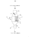
本実施形態に係る排気ガス温度制御装置20について以下に詳述する。図2は第1の実施形態に係る排気ガス温度制御装置の概略構成を示す外観斜視図である。図3は図2に示す3−3線にて切断した、第1の実施形態に係る排気ガス温度制御装置の模式的な横断面図である。
The exhaust gas
排気ガス温度制御装置20は、ケース201(筐体)、第1の流路管21、第2の流路管22、蓄熱体30、加熱部材31、断熱材23、流路切替弁25を備えている。なお、後述する制御ユニット60を含まない場合、排気ガス温度制御装置20は、排気ガス温度調整装置と呼ばれても良い。ケース201は、ステンレス鋼、酸化防止処理が施された鋼板から形成されている。第1の流路管21は排気ガスが流れる第1の流路部21aを規定し、第2の流路管22は排気ガスが流れる第2の流路部22aを規定し、第1の流路管21と第2の流路管22とは平行に配置されている。ケース201は、排気ガスを内部に導入するための導入部20aと排気ガスを外部に排出するための排出部20bとを備えている。導入部20aと第1の流路管21および第2の流路管22、排出部20bと第1の流路管21および第2の流路管22とは連通されている。なお、第1の流路管21および第2の流路管22は、中空矩形形状を有しているが、円筒形状並びに他の形状を有していても良い。
The exhaust gas
流路切替弁25は、ケース201の導入部20a側に、排気ガスが流れる流路管を第1の流路管21と第2の流路管22との間で切り替えるために備えられている。流路切替弁25としては、図示するように一端に備えられている軸を中心にして板状の弁体が揺動することによって流路を選択的に切り替える切替弁、内部に連通路を有する回転弁体が1軸を中心に回動することによって流路を選択的に切り替える切替弁、板状の弁体が直線移動することによって流路を選択的に切り替える切替弁等を用いることができる。弁体を駆動するアクチュエータとしては、ステッピングモータ等のモータ、電磁式のアクチュエータ、空気、オイルといった流体式のアクチュエータが用いられ得る。なお、後述するように、流路は、選択的、すなわち、排他的に切り替えられなくても良い場合があり、流路切替弁25としては、第1および第2の流路管21、22の双方に対して導入部20aから導入された排気ガスを導くことができることが求められる。流路切替弁25は、各流路管21、22に対してそれぞれ備えられていても良い。この場合には、一方の流路管を塞いだ上で、他の流路管に流れる排気ガス流量を調整することができる。すなわち、各流路管における外気ガス流量をそれぞれ独立して制御することができる。
The flow
蓄熱体30は、第1の流路管21の内部に部分的に配置されている。蓄熱体30は、第1の流路管21の形状に合わせて矩形形状を有しているが円柱形状等他の形状を有していても良い。蓄熱体30は、内部に排気ガスの流動を許容する内部流路を備えるセラミックス材、金属粉末の焼結体、メタルハニカム、エキスパンドメタル等を用いることができる。また、蓄熱体30として、溶融塩等による潜熱蓄熱体を用いることもできる。なお、内部流路は、意図的に形成された流路、たとえば直線流路であっても良く、材料の性質上形成される空隙により形成される流路、たとえば惰行流路であっても良い。なお、蓄熱体30は、必要な熱容量に応じて、第1の流路管21の全部に配置されても良い。
The
加熱部材(加熱器)31は、蓄熱体30に内包されている。図2および3の例では、第1の流路管21が矩形形状を有しており、これに合わせて蓄熱体30も矩形形状を有しているので、加熱部材31は矩形渦巻き形状の断面を有する形状を備えているが、円形渦巻き形状の断面を有する形状を備えていても良い。加熱部材31は、蓄熱体30に熱を蓄熱させるために用いられるので、蓄熱体30の一部または全部に内包されていても良く、あるいは、蓄熱体30の外周面の一部または全部に近接配置または接合されていても良い。加熱部材31は、複数の金属製の平板または波板、あるいは金属製の平板および波板が離間して積層されることにより形成され、板材自身が通電により発熱する加熱部材であっても良い。この場合、金属製の板材には発熱表面積を増大させるために穿孔処理あるいは凹凸処理が施されていることが望ましい。加熱部材31としては、棒状形状を有し排気ガスの流動方向に沿って蓄熱体30の内部流路に内挿されている複数の加熱部材が用いられても良い。なお、本実施形態における、加熱部材とは、周囲を絶縁材で覆われておらず、部材通電により部材自身が発熱する抵抗発熱体(発熱部材)であって、ニクロム線、銅線、タングステン線といった線状の、またはステンレス材、銅材、アルミニウム材といった板状の裸の金属材であっても良く、また、熱容量が小さく、蓄熱体として機能しない炭化ケイ素、カーボン等の非金属材であっても良い。あるいは、ケース内においてマグネシア等の粉末無機絶縁物に覆われて配置されている抵抗発熱体を備える加熱部材、すなわち、一般的にヒーターと呼ばれる態様の加熱部材であっても良い。
The heating member (heater) 31 is contained in the
なお、加熱部材31が、板材が積層されることによって渦巻き形状の断面を有する態様を備える場合には、加熱部材31を蓄熱体30として扱っても良い。すなわち、各金属製の板材は発熱部材並びに蓄熱部材として機能し得るため、所定の熱容量を有する蓄熱体30としても機能する。この場合、積層されている各板材間の離間空間が内部流路として機能し得る。さらに、加熱部材31は、蓄熱体30に内包されていなくても良く、蓄熱体30の上流側(エンジン側)および下流側の少なくともいずれか一方に近接して配置されていても良い。すなわち、蓄熱体30を加熱して蓄熱させることができればその配置態様は問わない。
In the case where the
第1の流路管21および第2の流路管22と、ケース201との間には断熱材23が配置または充填されている。断熱材23としては、たとえば、セラミック製のシート材、円筒状の硬質セラミック材、発泡性のセラミック材等が用いられる。断熱材23を備えることによって、金属製のケース201への熱伝導量を抑制し、排気ガス温度制御装置20の保温効率が所望のレベルに維持され得る。なお、ケース201は更なる断熱性向上のために、空気層を挟む2重壁構造を備えていても良い。
A
車両の運転状態に応じた流路切替弁25の切り替えの態様および加熱部材31による蓄熱体30の加熱の態様、すなわち、第1の実施形態に係る排気ガス温度制御装置の動作態様について図4〜図9を参照して説明する。図4は冷間始動時における第1の実施形態に係る排気ガス温度制御装置の動作状態を示す説明図である。図5は定常運転時における第1の実施形態に係る排気ガス温度制御装置の動作状態を示す説明図である。図6は減速時および低負荷時における第1の実施形態に係る排気ガス温度制御装置の動作状態を示す説明図である。図7は加速時における第1の実施形態に係る排気ガス温度制御装置の動作状態を示す説明図である。図8は急加速時または蓄熱体が十分に蓄熱していない加速時における第1の実施形態に係る排気ガス温度制御装置の動作状態を示す説明図である。図9は高負荷時およびDPF再生時における第1の実施形態に係る排気ガス温度制御装置の動作状態を示す説明図である。
About the mode of switching of the flow
車両の運転状態が冷間始動状態にある場合には、図4に示すように、流路切替弁25は、第1の流路管21を塞ぎ、エンジン510からの排気ガスを第2の流路管22、すなわち、第2の流路部22aへと導くように切り替えられる。冷間始動時にあっては、排気ガス温度は低く(たとえば、50℃程度)、蓄熱体30を排気ガスに曝すと蓄熱体30の温度(蓄熱量)は低下し、また、蓄熱体30にも熱が蓄えられていないので排気ガスと蓄熱体30とを接触させても排気ガスの温度上昇は見込めないからである。また、スイッチ61は開かれており、加熱部材31に対する通電は行われない。なお、排出部20bには、バッテリによって通電される第2の加熱部材35が備えられており、冷間始動時には、通電されて、排気ガスを加熱するために用いられる。
When the driving state of the vehicle is in a cold start state, as shown in FIG. 4, the flow
車両の運転状態が定常運転状態にある場合には、図5に示すように、流路切替弁25は、第1の流路管21および第2の流路管22の双方を導入部20aと連通し、エンジン510からの排気ガスを第1の流路管21および第2の流路管22、すなわち、第1の流路部21aおよび第2の流路部22aへと導くように切り替えられる。定常運転時にあっては、排気ガス温度制御装置に導入される排気ガス温度は200℃程度まで上昇し、蓄熱体30を排気ガスに曝すことによって蓄熱体30を加熱し、蓄熱体30に蓄熱させることができるからである。スイッチ61は開かれており、加熱部材31に対する通電は行われず、また、第2の加熱部材35に対する通電も行われない。
When the driving state of the vehicle is in the steady state, as shown in FIG. 5, the flow
車両の運転状態が減速時・低負荷状態にある場合には、図6に示すように、流路切替弁25は、第1の流路管21を塞ぎ、エンジン510からの排気ガスを第2の流路管22、すなわち、第2の流路部22aへと導くように切り替えられる。本実施形態に係る車両は、後述するように、減速時、オルタネータによって減速時の運動エネルギーを電気エネルギーとして回収することによって回生電力を得ることができる。そこで、減速時には、スイッチ61を閉じ、回生電力を用いて加熱部材31を発熱させ、蓄熱体30に蓄熱させる。また、低負荷時であって、車載バッテリの蓄電容量に余裕がある場合には、スイッチ61を閉じ、車載バッテリの電力を用いて加熱部材31を発熱させ、蓄熱体30に蓄熱させる。いずれの場合においても、第1の流路管21を塞ぐのは、排気ガスによって加熱部材31が発生した熱、あるいは、蓄熱体30の熱が奪われることを防止し、より高い熱量を蓄熱体30に蓄えさせるためである。また、定常運転状態からの減速または低負荷状態への移行時には、NOx、HC、CO等はほとんど排出されず、加熱部材31または蓄熱体30によって加熱する必要はないからである。なお、第2の加熱部材35に対する通電も行われない。
When the driving state of the vehicle is in the deceleration state / low load state, as shown in FIG. 6, the flow
車両の運転状態が加速状態にあり、蓄熱体30が十分に蓄熱している場合には、図7に示すように、流路切替弁25は、第2の流路管22を塞ぎ、エンジン510からの排気ガスを第1の流路管21、すなわち、第1の流路部21aへと導くように切り替えられる。加速時にあっては、エンジン負荷も高まり、NOxの排出量も増加すると共に、排気ガス流量自体が増大する。したがって、排気ガスを直接SCR装置14に導入するとSCR装置14の温度は作動適温以下になることもある。そこで、SCR装置14を十分に活性化させるために、蓄熱体30が蓄えている熱によって排気ガスを加熱し、増大するNOx量を処理できるようSCR装置14の温度を作動適温まで上昇させる。また、スイッチ61は開かれており、加熱部材31に対する通電は行われず、第2の加熱部材35に対する通電も行われない。
When the driving state of the vehicle is in the acceleration state and the
車両の運転状態が急加速状態にある場合、または、車両の運転状態が加速状態にあって蓄熱体30が十分に蓄熱していない場合には、図8に示すように、流路切替弁25は、第2の流路管22を塞ぎ、エンジン510からの排気ガスを第1の流路管21、すなわち、第1の流路部21aへと導くように切り替えられる。また、第2の加熱部材35に対する通電も行われる。急加速時にあっては、エンジン負荷も高まり、NOxの排出量も増加すると共に、排気ガス流量が極めて増大するため、蓄熱体30が蓄えている熱だけでは排気ガスを十分に加熱することができず、不足する熱量を第2の加熱部材35による加熱によって補うためである。また、加速時であって、蓄熱体30の蓄熱量が十分でない場合には、増大する排気ガス流量に対して、蓄熱体30が蓄えている熱だけでは排気ガスを十分に加熱することができず、不足する熱量を第2の加熱部材35による加熱によって補うためである。なお、スイッチ61は開かれている。また、第2の加熱部材35の通電による熱および蓄熱体30の蓄熱によっては熱量が不足する場合には、第2の加熱部材35に加えて、加熱部材31を回生電力以外の電力、たとえば、バッテリ42の電力を用いて発熱させても良く、あるいは、第2の加熱部材35を発熱させることなく加熱部材31のみを発熱させても良い。
When the driving state of the vehicle is in the rapid acceleration state, or when the driving state of the vehicle is in the acceleration state and the
車両の運転状態が高負荷状態またはDPF再生状態にある場合には、図9に示すように、流路切替弁25は、第2の流路管22を塞ぎ、エンジン510からの排気ガスを第1の流路管21、すなわち、第1の流路部21aへと導くように切り替えられる。高負荷時またはDPF再生時にあっては、排気ガス温度は短時間で400℃程度まで上昇し、SCR装置14においてNH3の漏れ出しが生じる傾向にある。そこで、蓄熱体30によって過昇温の排気ガスの熱エネルギーを吸収し、排気ガス温度の上昇速度を抑制し、NH3の漏れ出しを抑制する。なお、スイッチ61は開かれており、加熱部材31に対する通電は行われず、第2の加熱部材35に対する通電も行われない。
When the driving state of the vehicle is in the high load state or the DPF regeneration state, as shown in FIG. 9, the flow
図2および図3に示す本実施形態に係る排気ガス温度制御装置20は、水平方向に平行に並ぶ第1の流路管21および第2の流路管22を備えているが、図10に示すように、鉛直方向に並ぶ第1の流路管21および第2の流路管22を備えていても良い。図10は第1の実施形態に係る排気ガス温度制御装置の変形例を示す説明図である。たとえば、水平方向に搭載スペースがない場合には、鉛直(垂直)方向に搭載スペースを見出すことによって、第1の実施形態に係る排気ガス温度制御装置20を車両に搭載することができる。
The exhaust gas
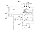
図11は第1の実施形態に係る蓄熱体を備える車両における電装部品間における電気的な接続を概略的に示すブロック図である。車両500は、エンジン510の駆動力によって駆動されるオルタネータ(発電機)40を備えている。エンジン510は、クランクシャフト(図示しない)から取り出される駆動力(出力)をオルタネータ40に提供するためのエンジン側プーリー511を備えている。オルタネータ40は、エンジン510から提供される駆動力が入力されるオルタネータ側プーリー401を備えている。エンジン側プーリー511とオルタネータ側プーリー401とは、ベルト512によって機械的に接続されており、ベルト512を介して、エンジン510の駆動力がオルタネータ40に伝達される。
FIG. 11 is a block diagram schematically showing the electrical connection between the electric components in the vehicle provided with the heat storage body according to the first embodiment.
車両500は、流路切替弁25、車両補機41、バッテリ42、制御ユニット60、第1のリレー61、第2のリレー62、第3のリレー63、第1の温度センサ191、第2の温度センサ192および第3の温度センサ193を備えている。流路切替弁25は、上述の構成を備えており、制御ユニット60とは制御信号線によって接続され、制御ユニット60からの制御信号によって、アクチュエータが弁体を駆動することによって、排気ガスの流路を第1の流路管21、第2の流路管22、または第1および第2の流路管21、22に切り替える。制御ユニット60は、排気ガス温度制御装置20から排出される排気ガスの温度を調整する温度制御部として機能する。
The
車両補機41は、オルタネータ40により出力される電力またはバッテリ42に蓄電されている電力によって、駆動される(電力を消費する)車両走行と共に用いられる補機であり、たとえば、ヘッドライト、オーディオ、ナビゲーションシステム、電気式ヒーターが該当する。
The
オルタネータ40の出力端子は、第1のリレー61を介して加熱部材31に電気的に接続されていると共に、第3のリレー63を介して、車両補機41に電気的に接続され、さらに電流計64を介してバッテリ42のプラス端子(+)に電気的に接続されている。バッテリ42のプラス端子(+)は第2のリレー62を介して第2の加熱部材35に電気的に接続されている。なお、オルタネータ40から車両補機41およびバッテリ42に至る配線経路には電圧を昇圧または降圧するためのDC/DCコンバータが配置されていても良い。オルタネータ40、車両補機41、加熱部材31、第2の加熱部材35の接地側端子は、ボディーアースを介してバッテリ42のマイナス端子(−)と電気的に接続されている。
The output terminal of the
第1のリレー61は、加熱部材31をオンまたはオフ、すなわち、加熱部材31に対する電力の供給または遮断の切り替えを行うスイッチである。第2のリレー62は、第2の加熱部材35をオンまたはオフ、すなわち、第2の加熱部材35に対する電力の供給または遮断の切り替えを行うスイッチである。第3のリレー63は、両補機41およびバッテリ42に対するオルタネータ40により発電された電力の供給または遮断の切り替えを行うスイッチである。第1〜第3のリレー61〜63は、制御ユニット60と制御信号線を介して接続されており、制御ユニット60からの制御信号によってオン(閉)またはオフ(開)される。電流計64は、信号線を介して制御ユニット60に対して、検出されたバッテリ42の出力電流を提供する。第1の温度センサ191は排気ガス温度制御装置20(蓄熱体30)の温度を検出するために用いられ、第2の温度センサ192は排気ガス温度制御装置20に導入される排気ガスの温度を検出するために用いられ、共に、制御ユニット60に対して信号線で接続されている。
The
本実施形態においては、第1のリレー61をオンし、第3のリレー63をオフすることによって、オルタネータ40により発電された電力を直接、すなわち、バッテリ42への蓄電を介することなく、加熱部材31に供給することができる。たとえば、車両減速時にバッテリ42が規定の満充電状態にありオルタネータ40から出力される電力が余剰電力となる条件下において、オルタネータ40を作動させて加熱部材31を発熱するために電力を供給することができる。加熱部材31により生成された熱エネルギーは、蓄熱体30を加熱するために用いられ、蓄熱体に熱が蓄熱される。この結果、車両の運動エネルギーを捨てることなく、電気エネルギー、更には、熱エネルギーに変換して、蓄熱体30に蓄えることが可能となる。蓄熱体30に蓄えられた熱は、既述のように、車両の運転状態に応じて排気ガスの温度を上昇させるために用いられる。また、車両の運転状態が低負荷状態にあり、バッテリ42の電池容量に余裕がある場合には、制御ユニット60は、第1および第3のリレー61および63をオンすることによって、バッテリ42からの電力によって加熱部材31を発電させても良い。第2の加熱部材35は、第2のリレー62をオンすることにより、バッテリ42からの電力によって発熱する。
In the present embodiment, by turning on the
第1の実施形態における、排気ガス温度制御装置20の作動制御について図12を参照して説明する。図12は第1の実施形態における排気ガス温度制御装置の動作を制御するための第1の処理ルーチンを示すフローチャートである。本処理ルーチンは、制御ユニット60によって実行される。なお、制御ユニット60には、少なくとも、図示しない、中央演算装置(CPU)、メモリおよび外部機器と制御信号、検出信号のやりとりを行うために入出力インタフェースが備えられている。
Operation control of the exhaust gas
制御ユニット60は、車両の始動と共に本処理ルーチンを開始し、車両に備えられている種々のセンサによって車両の運転状態を検知する。たとえば、制御ユニット60は、アクセルペダル開度センサから入力される入力信号、排気ガス温度制御装置20の前段に配置されている温度センサ192から入力される入力信号に基づいて車両の運転状態が加速状態、減速状態、定常運転状態にあるか否かを判断し、DPF制御信号によってDPF再生処理実行中であるか否かを判断し、第3の温度センサ193から入力される冷却液温度を示す入力信号に基づいて低温始動時であるか否かを判断することができる。
The
制御ユニット60は、車両の運転状態が低温始動状態にあるか否かを判定し(ステップS100)、低温始動状態にあると判定した場合には(ステップS100:Yes)、流路切替弁25に制御信号を送信して、第1の流路管21(第1の流路部21a)を閉鎖させる(ステップS102)。すなわち、図4に示したように、導入部20aと第2の流路管22(第2の流路部22a)とを連通し、排気ガスを第2の流路部22aに導く。制御ユニット60は、エンジン510の冷却液温度を検知する第3の温度センサ193から入力された冷却液温度に基づいて車両が冷間始動状態にあるか否かを判定する。たとえば、第3の温度センサ193によって検出された冷却液温度が、0℃〜20℃である場合には、冷間始動状態にあると判断される。あるいは、第2の温度センサ192によって検知された排気ガス温度制御装置20に導入される排気ガス温度に基づいて(たとえば、排気ガス温度が50℃以下)、あるいは、冷却液温度と排気ガス温度とに基づいて、冷間始動状態にあるか否かが判断されても良い。制御ユニット60は、第3のリレー63をオフし(ステップS104)、第2のリレーをオンして(ステップS106)、運転状態の検知へリターンする。第3のリレー63がオフ位置に切り替えられることによって、加熱部材31がオフされ(電力回路から切り離され)、第2のリレー62がオン位置に切り替えられることによって、第2の加熱部材35がオンされる。この結果、排気ガス温度制御装置20に導入された排気ガスは、第2の加熱部材35によって加熱され昇温され、後段のSCR装置14を早期に適当な作動温度まで上昇させることができる。
The
なお、制御ユニット60は、第3のリレー63に対するオフ信号(開信号)の送信に先立って、第3のリレー63がオン位置にあるか否かを判断し、オン位置にある場合にのみ第3のリレー63に対してオフ信号を送信しても良く、あるいは、第3のリレー63の現位置によらず第3のリレー63に対してオフ信号を送信しても良い。この手順は、流路切替弁25に対する弁位置の切替制御、第1および第2のリレー61、62に対するオン・オフ制御においても同様である。
The
制御ユニット60は、車両の運転状態が低温始動状態にないと判定した場合には(ステップS100:No)、車両の運転状態が減速状態にあるか否かを判定する(ステップS108)。制御ユニット60は、車両の運転状態が減速状態にあると判定した場合には(ステップS108:Yes)、流路切替弁25に制御信号を送信して、図6に示すように、第1の流路管21(第1の流路部21a)を閉鎖させ(ステップS110)、導入部20aと第2の流路管22(第2の流路部22a)とを連通し、排気ガスを第2の流路部22aに導く。すなわち、排気ガスの流れに蓄熱体30が曝されないようにして、以下に示す加熱部材31による蓄熱体30に対する蓄熱処理を効率的に実行する。制御ユニット60は、アクセルペダル開度センサからの入力信号がアクセルペダルがオフ状態(開度0)を示す場合には、車両の運転状態は減速状態(惰行状態)にあると判断する。制御ユニット60は、第2および第3のリレー62、63をオフし(ステップS112)、第1のリレー61をオンして(ステップS114)、運転状態の検知へリターンする。第2および第3のリレー62、63がオフ位置に切り替えられることによって、第2の加熱部材35がオフされ(電力回路から切り離され)、バッテリ42とオルタネータ40との接続が切り離される。一方、第1のリレー61がオンされることによって、減速に伴いオルタネータ40によって生成された回生電力は、加熱部材31に供給され、加熱部材31は発熱し、蓄熱体30は蓄熱される。
When it is determined that the driving state of the vehicle is not in the low temperature starting state (step S100: No), the
なお、車両の運転状態が減速状態にある場合に加えて、車両が低負荷状態にあるか否かを判定し、低負荷状態にある場合に、減速状態にある場合と同様にして、排気ガス温度制御装置20の排気ガス流路を切り替えるようにしても良い。低負荷状態にあるか否かの判定は、たとえば、アクセルペダルの開度が所定開度未満であることと、車速が略一定であることとに基づいて実行されて良い。低負荷状態にある場合には、回生電力を得ることはできないので、バッテリ42の電力を用いて加熱部材31に対する電力供給が行われる。したがって、制御ユニット60は、第1および第3のリレー61、63をオフし、第2のリレー62をオンする。低負荷状態にある場合の蓄熱体30に対する蓄熱処理は、バッテリ42に余剰電力が残されている場合、オルタネータ40による充電が不要な状態である場合、に実行される。
In addition to when the driving state of the vehicle is in the decelerating state, it is determined whether or not the vehicle is in the low load state, and when in the low load state, the exhaust gas is the same as in the decelerating state. The exhaust gas flow path of the
制御ユニット60は、車両の運転状態が減速状態にないと判定した場合には(ステップS108:No)、車両の運転状態が加速状態にあるか否かを判定する(ステップS116)。制御ユニット60は、車両の運転状態が加速状態にあると判定した場合には(ステップS116:Yes)、流路切替弁25に制御信号を送信して、図7に示すように、第2の流路管22(第2の流路部22a)を閉鎖させ(ステップS118)、導入部20aと第1の流路管21(第1の流路部21a)とを連通し、排気ガスを第1の流路部21aに導く。制御ユニット60は、たとえば、アクセルペダルの開度が所定角度以上であること、車両の時間あたりの車速の変化が所定値以上である場合には、車両の運転状態は加速状態にあると判断する。制御ユニット60は、第1〜第3のリレー61〜63をオフして(ステップS120)、運転状態の検知へリターンする。第1〜第3のリレー61〜63がオフ位置に切り替えられることによって、加熱部材31および第2の加熱部材35がオフされ(電力回路から切り離され)、バッテリ42とオルタネータ40との接続が切り離される。加速時には、排気ガスの流量が増大し、NOx量も増大するので、蓄熱体30を排気ガスに曝すことによって、蓄熱体30に蓄えられている熱エネルギーによって排気ガスを加熱して、排気ガス温度制御装置20から排出される排気ガス温度を所望の温度まで上昇させる。なお、所望の温度とは、たとえば、SCR装置14が適切に作動できる温度域の温度である。
When it is determined that the driving state of the vehicle is not in the decelerating state (step S108: No), the
なお、車両の運転状態が加速状態にある場合に加えて、車両が急加速状態にあるか否かを判定し、図8に示すように、急加速状態にある場合には、第2のリレー62をオン(ステップS122)してバッテリ42の電力によって第2の加熱部材35を発熱させても良い。急加速状態にあっては、排気ガスの流量も大幅に増大し、蓄熱体30に蓄えられている熱量だけでは、排気ガスを所望温度まで昇温させることができない場合がある。そこで、第2の加熱部材35によって不足する熱量を補う。急加速状態にあるか否かの判定は、たとえば、アクセルペダルが床一杯に踏み込まれた際にオンされるキックダウンスイッチがオンされたか否かによって検出することができる。また、加速状態にある場合に、蓄熱体30の温度が所定温度よりも低い場合に、急加速状態である場合と同様にして第2の加熱部材35による排気ガスの加熱が行われても良い。この場合にも、加速状態での流速のある排気ガスを十分に昇温させることができないことがあり、排気ガス温度制御装置20から排出される排気ガスを所望温度まで上昇させるためには、第2の加熱部材35による加熱が必要となる。蓄熱体30の温度は、たとえば、第1の温度センサ191によって検出することができる。
In addition to the case where the driving state of the vehicle is in the accelerating state, it is determined whether or not the vehicle is in the rapid accelerating state, and as shown in FIG. 62 may be turned on (step S122) and the power of the
制御ユニット60は、車両の運転状態が加速状態にないと判定した場合には(ステップS116:No)、車両の運転状態が高負荷状態にあるか否かを判定する(ステップS124)。制御ユニット60は、車両の運転状態が高負荷状態にあると判定した場合には(ステップS124:Yes)、流路切替弁25に制御信号を送信して、図9に示すように、第2の流路管22(第2の流路部22a)を閉鎖させ(ステップS126)、導入部20aと第1の流路管21(第1の流路部21a)とを連通し、排気ガスを第1の流路部21aに導く。制御ユニット60は、たとえば、アクセルペダルの開度のが所定値以上であること、燃料噴射量、走行ギヤ、車速に応じて、車両が高負荷状態にあるか否かを判定することができる。すなわち、アクセルペダル開度が大きく、車速が低い場合には高負荷状態であると言える。制御ユニット60は、第1〜第3のリレー61〜63をオフして(ステップS128)、運転状態の検知へリターンする。第1〜第3のリレー61〜63がオフ位置に切り替えられることによって、加熱部材31および第2の加熱部材35がオフされ(電力回路から切り離され)、バッテリ42とオルタネータ40との接続が切り離される。高負荷時には、排気ガスの温度が高くなるので、蓄熱体30を排気ガスに曝すことによって、排気ガスが有する熱エネルギーの一部を蓄熱体30によって吸収し、排気ガス温度制御装置20に導入された排気ガスの温度を所望の温度まで低下させて排気ガス温度制御装置20から排出させる。なお、所望の温度とは、たとえば、SCR装置14においてNH3漏れが起こらない温度域の温度である。
If the
なお、車両の運転状態が高負荷状態にある場合に加えて、車両がDPF再生処理状態にあるか否かを判定し、図9に示すように、DPF再生処理状態にある場合には、第1〜第3のリレー61〜63をオフしても良い。DPF再生処理状態にあっては、DPF触媒を再生するために、ポスト噴射が実行され燃料由来の炭化水素がDPF13に供給される。この結果、燃料由来の炭化水素はDPF13にて触媒燃焼され、排気温度は450℃以上まで上昇し、捕集された粒子状物質が酸化され強制再生される。DPF13は、排気ガス温度制御装置20の前段に配置されているので、排気ガス温度制御装置20に導入される排気ガス温度も大幅に上昇する。そこで、気ガスが有する熱エネルギーの一部を蓄熱体30によって吸収し、所望の温度まで低下させた排気ガスを排気ガス温度制御装置20から排出させる。
In addition to the case where the driving state of the vehicle is in the high load state, it is determined whether the vehicle is in the DPF regeneration processing state, and as shown in FIG. The first to
制御ユニット60は、車両の運転状態が高負荷状態にないと判定した場合には(ステップS124:No)、車両の運転状態は定常走行状態にあると判定して、流路切替弁25に制御信号を送信して、図5に示すように、第1および第2の流路管21、22(第1の流路部21a、第2の流路部22a)を共に開き(ステップS130)、運転状態の検知へリターンする。第1および第2の流路管21、22を共に開くとは、弁体を中立位置に位置させることによって、導入部20aと第1の流路管21(第1の流路部21a)および第2の流路管22(第2の流路部22a)とを連通し、排気ガスを第1および第2の流路部21a、22aに導くことを意味する。定常走行状態においては、排気ガスの流量も加速時よりも少なく、また、排気ガス温度も高負荷時よりも低いので、一部は直接、排気ガス温度制御装置20から排出し、一部は蓄熱体30の蓄熱に用いられた後に排気ガス温度制御装置20から排出される。
When the
排気ガス温度制御装置20の第2の作動制御について図13を参照して説明する。図13は第1の実施形態における排気ガス温度制御装置の動作を制御するための第2の処理ルーチンを示すフローチャートである。第1の処理ルーチンでは、もっぱら車両の運転状態に基づいて、排気ガス温度制御装置20の作動が制御されたが、第2の処理ルーチンでは、排気ガス温度および蓄熱体30の温度に基づいて排気ガス温度制御装置20の作動が制御される。
The second operation control of the exhaust gas
制御ユニット60は、排気ガス温度制御装置20に導入される排気ガスの温度GTが第1の所定温度T1以上であるか否かを判定する(ステップS200)。排気ガス温度GTは、第2の温度センサ192によって検出可能である。第1の所定温度T1は、高負荷時またはDPF再生処理時における排気ガス温度であり、たとえば、400℃である。排気ガス温度GTが第1の所定温度T1以上である場合には、後段のSCR装置14におけるNH3漏れを考慮すると、蓄熱体30によって排気ガス温度を下げることが望ましいことは既述の通りである。
The
制御ユニット60は、GT≧T1であると判定すると(ステップS200:Yes)、蓄熱体30の温度HTが第2の所定温度T2未満であるか否かを判定する(ステップS202)。蓄熱体温度HTは、第1の温度センサ191によって検出可能である。第2の所定温度T2は、導入された排気ガスの温度を上昇させることのない第1の所定温度T1よりも低い温度であり、たとえば、300℃<T1<400℃である。制御ユニット60は、HT<T2であると判定すると(ステップS202:Yes)、流路切替弁25に制御信号を送信して、図9に示すように、第2の流路管22(第2の流路部22a)を閉鎖させ(ステップS126)、導入部20aと第1の流路管21(第1の流路部21a)とを連通し、排気ガスを第1の流路部21aに導く。この結果、排気ガス温度制御装置20は、高温の排気ガスを所定温度の排気ガスとして、あるいは、さらに加温することなく、排出することができる。この後、処理ステップは、運転状態の検知へリターンする。
When determining that GTGTT1 (step S200: Yes), the
制御ユニット60は、HT≧T2であると判定すると(ステップS202:No)、流路切替弁25に制御信号を送信して、第1の流路管21(第1の流路部21a)を閉鎖させ(ステップS206)、導入部20aと第2の流路管22(第2の流路部22a)とを連通し、排気ガスを第2の流路部22aに導く。この後、処理ステップは、運転状態の検知へリターンする。蓄熱体30の温度HTが第2の所定温度T2以上である場合には、蓄熱体30による十分な排気ガス温度の低下を期待できないので、また、蓄熱体30の温度HTが400℃以上の場合には、排気ガス温度をさらに上昇させることになるので、排気ガスを蓄熱体30に曝すことなく、排気ガスを排気ガス温度制御装置20から排出させる。
When the
制御ユニット60は、GT<T1であると判定すると(ステップS200:No)、排気ガス温度GTが第3の所定温度T3未満であるか否かを判定する(ステップS208)。第3の所定温度T3は、第1の所定温度T1よりも低く、後段のSCR装置14を活性化させるためには不足する温度であり、たとえば、100℃である。制御ユニット60は、GT<T3であると判定すると(ステップS208:Yes)、蓄熱体温度HTが第4の所定温度T4以上であるか否かを判定する(ステップS210)。第4の所定温度T4は、第2の所定温度T2および第3の所定温度T3よりも高く、後段のSCR装置14を活性化させることができる温度であり、たとえば、200℃である。制御ユニット60は、HT≧T4であると判定すると(ステップS210:Yes)、流路切替弁25に制御信号を送信して、第2の流路管22(第2の流路部22a)を閉鎖させ(ステップS212)、導入部20aと第1の流路管21(第1の流路部21a)とを連通し、排気ガスを第1の流路部21aに導く。この結果、排気ガス温度制御装置20に導入された排気ガスは、より温度の高い蓄熱体30によって加熱され、所望温度または所望温度に近い温度の排気ガスを排出することができる。この後、処理ステップは、運転状態の検知へリターンする。
If it is determined that GT <T1 (step S200: No), the
制御ユニット60は、GT≧T3であると判定すると(ステップS208:No)、または、HT<T4であると判定すると(ステップS210:No)、流路切替弁25に制御信号を送信して、第1の流路管21(第1の流路部21a)を閉鎖させ(ステップS214)、導入部20aと第2の流路管22(第2の流路部22a)とを連通し、排気ガスを第2の流路部22aに導く。この結果、排気ガス温度制御装置20に導入された排気ガスは、蓄熱体30を介することなく、SCR装置14の動作に十分な温度で排気ガス温度制御装置20から排出される。なお、後述するステップS216およびS218が実行されない場合には、導入部20aと第1および第2の流路管21、22(第1および第2の流路部21a、22a)とを連通し、排気ガスを第1および第2の流路部21a、22aに導いても良い。この場合、SCR装置14の動作に十分な温度の排気ガスが第2の流路部22aを介して排出されると共に、第1の流路部21aを流れる排気ガスによる蓄熱体30に対する蓄熱を実行することができる。
If the
制御ユニット60は、第2および第3のリレー62、63をオフし(ステップS216)、第1のリレー61をオンして(ステップS218)、運転状態の検知へリターンする。ステップS216およびS218は、車両の運転状態に応じて回生電力が得られた場合に実行されることが望ましいが、バッテリ42の残存電力量に余裕がある場合には、バッテリ42からの電力を用いる場合に実行されても良い。
The
第2および第3のリレー62、63がオフされ、第1のリレー61がオンされることによって、車両が減速状態にある場合には、オルタネータ40によって発電された回生電力が加熱部材31に供給され、加熱部材31が発熱する。この結果、蓄熱体30は、加熱部材31によって加熱され、蓄熱することができ、次回、ステップS204が実行される際に排気ガスを加熱するための熱量を蓄えることができる。
When the vehicle is in a decelerating state by turning off the second and
以上説明した第1の実施形態に係る排気ガス温度制御装置20によれば、排気ガスの熱エネルギーを蓄熱体30によって蓄熱し、蓄熱体30に蓄熱された熱によって排気ガスを昇温させることによって、排気ガス浄化装置に対して供給される排気ガスの温度を所望の温度域または所望の温度に制御することができる。電気式の加熱部材を用いる場合には立ち上がり時間を要するが、蓄熱体30の蓄熱を用いた排気ガスの加熱は立ち上がり時間を要することなく短時間で排気ガスの温度を昇温させることができる。また、蓄熱体30には加熱部材31が内包または蓄熱体30の近傍には加熱部材31が配置されているので、排気ガスのみに依存することなく蓄熱体30に蓄熱させることができる。さらに、加熱部材31に対しては、車両の減速時に得られる回生電力が供給されるので、加熱部材31を発熱させるための電力を得るために内燃機関510を余分に作動させる(燃料を消費する)必要はなく、減速時に放出される運動エネルギを電気エネルギに変換して、加熱部材31の発熱に用いることができる。
According to the exhaust gas
また、排気ガス温度が比較的高い場合には、蓄熱体30を排気ガスに曝すことによって、排気ガス温度を低減させることが可能となり、後段に備えられている排気ガス浄化装置に対して高温の排気ガスが供給されることに伴う問題、たとえば、SCR装置14におけるNH3漏れを抑制または防止することができる。
In addition, when the exhaust gas temperature is relatively high, it is possible to reduce the exhaust gas temperature by exposing the
以上の通り、第1の実施形態に係る排気ガス温度制御装置20によれば、エンジン510から排出される排気ガスの温度に依存せず、車両全体におけるエネルギー効率を低下させることなく、排気ガス温度を浄化装置の作動温度域に調整することができる。この結果、車両の運転状態に依存することなく、排気ガスを所望の浄化レベルまで浄化することができる。
As described above, according to the exhaust gas
第2の実施形態:
図14〜図16を参照して、第2の実施形態に係る排気ガス温度制御装置20Aについて説明する。より具体的には、車両の運転状態に応じた流路切替弁25の切り替えの態様および加熱部材31による蓄熱体30の加熱の態様について説明する。図14は冷間始動時における第2の実施形態に係る排気ガス温度制御装置の動作状態を示す説明図である。図15は減速時および低負荷時における第2の実施形態に係る排気ガス温度制御装置の動作状態を示す説明図である。図16は加速時における第2の実施形態に係る排気ガス温度制御装置の動作状態を示す説明図である。
Second embodiment:
An exhaust gas
第2の実施形態に係る排気ガス温度制御装置20Aは、蓄熱体30の直下にプリSCR37を備える点において第1の実施形態に係る排気ガス温度制御装置20と異なる。すなわち、第1の流路管21において、加熱部材31を含む蓄熱体30に加えて、プリSCR37が備えられている。すなわち、排気ガス温度制御装置20Aの後段に備えられるSCR装置14に加えて、排気ガス温度制御装置20A内にSCRが別途備えられている。
The exhaust gas
図14に示す冷間始動時においては、流路切替弁25は、第1の流路管21を塞ぎ、エンジン510からの排気ガスを第2の流路部22aへと導くように切り替えられる。また、第2の加熱部材35に対してはバッテリ42からの電力が供給され、排気ガスが加熱される。図15に示す減速時および低負荷時においては、流路切替弁25は、第1の流路管21を塞ぎ、エンジン510からの排気ガスを第2の流路部22aへと導くように切り替えられる。第1のリレー61はオンされ、加熱部材31に対して減速に伴う回生電力が供給され、加熱部材31が発熱することによって蓄熱体30が蓄熱される。また、低負荷時であって、車載バッテリの蓄電容量に余裕がある場合には、スイッチ61を閉じ、車載バッテリの電力を用いて加熱部材31を発熱させ、蓄熱体30に蓄熱させる。
At the time of cold start shown in FIG. 14, the flow
図16に示す加速時においては、流路切替弁25は、第2の流路管22を塞ぎ、エンジン510からの排気ガスを第1の流路部21aへと導くように切り替えられる。また、スイッチ61は開かれており、加熱部材31に対する通電は行われず、第2の加熱部材35に対する通電も行われない。加速時には、NOxの排出量も増加すると共に、排気ガス流量自体が増大する。第2の実施形態では、単に蓄熱体30によって排気ガスを加熱するに留まらず、プリSCR37を蓄熱体30の直下(直後)に配置することによって、蓄熱体30の蓄熱によって、プリSCR37の温度を尿素水の熱分解、加水分解反応に必要な温度まで効率よく上昇させることが可能となる。この結果、アンモニア(NH3)が円滑に生成され、排気ガス中のNOx成分から窒素(N2)および水(H2O)への変換を十分に実行することができる。なお、プリSCR37によって窒素(N2)および水(H2O)への変換が行われなかったNOx成分は、後段のSCR装置14において変換され得る。なお、第2の実施形態において、第2の加熱部材35は、第1の実施形態において説明した態様と同様にして作動させることができる。
At the time of acceleration shown in FIG. 16, the flow
以上説明した第2の実施形態に係る排気ガス温度制御装置20Aによれば、SCR装置14に加えて、排気ガス温度制御装置20A内にプリSCR37が備えられているので、SCR37を蓄熱体の蓄熱によって効率よく昇温させることが可能となり、排気ガス中に含まれるNOx成分の変換(分解)割合を向上させることができる。すなわち、プリSCR37が動作温度に達していないことを理由とする、NOx成分のすり抜けを低減または防止することが可能となり、後段のSCR装置14と相まって、NOx成分の浄化性能を向上させることができる。
According to the exhaust gas
変形例:
(1)上記各実施形態においては、蓄熱体30に設けられた第1の温度センサ191、蓄熱体30の前段に備えられた第2の温度センサ192によって、蓄熱体30、および排気ガスの温度が取得されているが、エンジン510の始動後からの経過時間に基づいて、あるいは、加熱部材31に対する通電履歴に基づいて、一律に各温度が求められても良い。
Modification:
(1) In the above embodiments, the temperature of the
(2)上記各実施形態に係る排気ガス温度制御装置20はSCR装置14の前段に備えられているので、SCR装置14に対して、定常的にNOx浄化に適当な温度の排気ガスを供給することが可能となり、この結果、SCR装置14では、従来、排気ガス温度の低下によりNOx浄化を実行できなかった条件下においてもNOx浄化が実行され得ることとなり、NOxの大気への排出量をさらに低減させることができる。また、従来、排気ガス温度を上昇させるためにDOC12やDPF13において実行されていた、燃料燃焼による排気ガス温度の上昇処理が不要となり、走行とは関係なく消費される燃料量を低減させることができる。
(2) Since the exhaust gas
(3)上記各実施形態に係る排気ガス温度制御装置20は、上記の構成の他、以下の構成を採っても良い。上記各実施形態に係る排気ガス温度制御装置20においては、DPF13とSCR装置14の間に排気ガス温度制御装置20が配置されていたが、排気ガス温度制御装置20は、DPF13の前段に配置されていても良い。この場合には、DPF13に導入される排気ガス温度を高温に維持することが可能となり、燃料噴射を伴う強制的な再生処理を伴うことなく、定期的に自発的な再生処理の実行が期待され得る。この結果、再生処理のために燃料を消費する必要がなくなり、車両の燃費性能を向上させることができる。
(3) The exhaust gas
なお、本明細書における浄化装置とは、触媒によって排気ガス中の特定の成分(物質)を非有害成分(物質)へ変換する、いわゆる化学反応式の浄化触媒に止まらず、排気ガス中の特定成分を捕集するフィルタ式浄化装置も含まれる。フィルタ式浄化装置においても、適当に再生動作を実行するための適性温度範囲が存在する場合があり、本実施形態に係る排気ガス温度制御装置20を用いれば、フィルタ式浄化装置に導入される排気ガス温度を適性温度範囲に維持することができ、フィルタ式浄化装置はエンジン510の運転状況に依存することなく広い条件下において所期の性能を発揮することができる。したがって、本実施形態に係る排気ガス温度制御装置20は、所定の温度範囲の排気ガスの導入により性能が発揮される浄化装置であれば、どのような浄化装置の前段に用いられても良く、そのような浄化装置の前段に用いられることによって浄化装置の性能を幅広い条件下で発揮させることができる。
Incidentally, the purification device in this specification is not limited to so-called chemical reaction type purification catalyst, which converts a specific component (substance) in exhaust gas into non-toxic components (substance) by a catalyst, and also identifies in exhaust gas. Also included are filter purifiers that capture components. Also in the filter-type purification device, there may be an appropriate temperature range for appropriately performing the regenerating operation, and if the exhaust gas
(4)上記各実施形態においては、ディーゼルエンジン510を例にとって説明したが、上記各実施形態に係る排気ガス温度制御装置20は、ガソリンエンジンにおける排気経路に配置され、ガソリンエンジン用の排気ガスの浄化システムを構成しても良い。ガソリンエンジンの排気ガス温度は、ディーゼルエンジンの排気ガス温度よりは高いが、エンジン始動当初から十分な排気ガスの浄化を実現するために、触媒が所期の性能を発揮する温度域まで触媒温度を上昇させるための種々の試みが成されている。たとえば、ガソリンエンジンの浄化装置として一般的に用いられている三元触媒をエキゾーストマニホールド直下に配置することによって触媒の早期暖気が試みられている。しかしながら、排気ガス温度の熱分布に依存して触媒の配置位置を決定する場合には、触媒の配置位置に自由度がなく、エンジン周りの設計に自由度がなかった。これに対して、各実施形態に係る排気ガス温度制御装置20を適用すれば、三元触媒の配置位置にかかわらず、早期暖気を実現することが可能となり、車両設計上の自由度が高まるという利点がある。
(4) In each of the above embodiments, the
(5)上記各実施形態においては、一の蓄熱体30が用いられているが、蓄熱体30は、複数の独立した蓄熱体から構成されても良い。この場合には各蓄熱体30間における排気ガス温度の拡散、混合により蓄熱体30内における排気ガスの温度分布の均一化を期待することができる。
(5) In each said embodiment, although the one
(6)上記各実施形態においては、排気ガス温度制御装置20は矩形箱型形状を有しているが、導入部20aから排出部20bcに至るまで複数回折り返された冗長な形状を備えていても良く、円筒形状を有していても良い。また、上記各実施形態においては、直線状に延びる排気ガス温度制御装置20を例にとって説明しているが、排気ガス温度制御装置20は、一部の構成または配管が他の構成または配管と交差する方向に配置され、折り返し状に形成された浄化システムに適用されても良い。例えば、車載時に地面に対して平行に配置される平行部と、平行部と交差する交差部とを有する折り返し形状を備え、排気ガスの流動方向への長さを短くした浄化システムに適用されても良い。なお、交差部は、地面に対して垂直な垂直部であり、垂直方向に嵩を有する浄化システムであっても良い。この場合、排気ガス温度制御装置20は平行部または交差部のいずれに配置されても良い。
(6) In each of the above embodiments, the exhaust gas
以上、実施例、変形例に基づき本発明について説明してきたが、上記した発明の実施の形態は、本発明の理解を容易にするためのものであり、本発明を限定するものではない。本発明は、その趣旨並びに特許請求の範囲を逸脱することなく、変更、改良され得ると共に、本発明にはその等価物が含まれる。例えば、発明の概要の欄に記載した各形態中の技術的特徴に対応する実施形態、変形例中の技術的特徴は、上述の課題の一部又は全部を解決するために、あるいは、上述の効果の一部又は全部を達成するために、適宜、差し替えや、組み合わせを行うことが可能である。また、その技術的特徴が本明細書中に必須なものとして説明されていなければ、適宜、削除することが可能である。 Although the present invention has been described above based on the examples and modifications, the above-described embodiment of the present invention is for the purpose of facilitating the understanding of the present invention, and does not limit the present invention. The present invention can be modified and improved without departing from the spirit and the scope of the claims, and the present invention includes the equivalents thereof. For example, the technical features in the embodiments corresponding to the technical features in the respective forms described in the section of the summary of the invention, and the technical features in the modified examples are for solving some or all of the problems described above, or Replacements or combinations can be made as appropriate to achieve part or all of the effects. Also, if the technical features are not described as essential in the present specification, they can be deleted as appropriate.
10…浄化システム
11…排気管
11a…マニフォールド
11b…マフラエンドパイプ
12…ディーゼル酸化触媒
13…ディーゼル微粒子フィルタ
14…選択触媒還元装置
15…ディーゼル酸化触媒
17…燃料噴射装置
18…尿素水噴射装置
191…第1の温度センサ
192…第2の温度センサ
193…第3の温度センサ
20…排気ガス温度制御装置
20A…排気ガス温度制御装置
20a…導入部
20b…排出部
201…ケース
21…第1の流路管
21a…第1の流路部
22…第2の流路管
22a…第2の流路部
23…断熱材
25…流路切替弁
30…蓄熱体
31…加熱部材
35…第2の加熱部材
40…オルタネータ
401…オルタネータ側プーリー
41…補機
42…バッテリ
500…車両
510…ディーゼルエンジン
511…エンジン側プーリー
512…ベルト
520…車輪
60…制御ユニット
61…第1のリレー
62…第2のリレー
63…第3のリレー
64…電流計
T1…第1の所定温度
T2…第2の所定温度
T3…第3の所定温度
T4…第4の所定温度
DESCRIPTION OF
Claims (6)
熱を蓄熱または放熱可能な蓄熱体と、
前記蓄熱体に熱を蓄熱させるための加熱部材と、
前記蓄熱体を内包し、排気ガスの流路を構成する第1の流路部と、
前記第1の流路部とは異なる、前記排気ガスの流路を構成する第2の流路部と、
前記排気ガスの流路を前記第1の流路部と前記第2の流路部の少なくともいずれか一方に切り替える切替部と、
前記切替部を制御することによって、前記内燃機関を搭載する車両の運転状態に応じて、前記蓄熱体に熱を蓄熱または前記蓄熱体から熱を放熱させて前記排気ガス温度制御装置から排出される排気ガスの温度を制御する温度制御部であって、
前記排気ガス温度が高負荷時または前記ディーゼル微粒子フィルタの再生処理時における第1の所定温度以上であり、前記蓄熱体の温度が前記第1の所定温度よりも低く、導入された排気ガス温度を上昇させない第2の所定温度未満の場合に、または、前記排気ガス温度が前記第1の所定温度よりも低く、前記排気ガス浄化装置の活性化には不足する第3の所定温度未満であり、前記蓄熱体の温度が前記第2の所定温度および前記第3の所定温度よりも高く、前記排気ガス浄化装置を活性化可能な第4の所定温度以上の場合に、前記第1の流路部に前記排気ガスを導くよう前記切替部を切り替える、温度制御部と
を備える、排気ガス温度制御装置。 Disposed downstream of Oite diesel particulate filter in an exhaust pipe of an internal combustion engine, is disposed upstream of the exhaust gas purifying device, and an exhaust gas temperature control device for adjusting the exhaust gas temperature definitive in the exhaust gas purification device,
A heat storage body capable of storing or releasing heat,
A heating member for storing heat in the heat storage body;
A first flow passage portion which contains the heat storage body and constitutes a flow passage of exhaust gas;
A second flow passage portion which constitutes a flow passage of the exhaust gas, which is different from the first flow passage portion;
A switching unit configured to switch the flow passage of the exhaust gas to at least one of the first flow passage unit and the second flow passage unit;
By controlling the switching unit , the heat storage body stores heat or the heat storage body releases heat according to the driving state of a vehicle equipped with the internal combustion engine, and the heat storage body is discharged from the exhaust gas temperature control device a temperature control unit for controlling the temperature of the exhaust gas,
The exhaust gas temperature is equal to or higher than a first predetermined temperature at the time of high load or at the time of regeneration of the diesel particulate filter, and the temperature of the heat storage body is lower than the first predetermined temperature. If the temperature is lower than the second predetermined temperature not to be raised, or the exhaust gas temperature is lower than the first predetermined temperature, the exhaust gas temperature is lower than the third predetermined temperature which is insufficient for activation of the exhaust gas purification device. When the temperature of the heat storage body is higher than the second predetermined temperature and the third predetermined temperature and is equal to or higher than a fourth predetermined temperature at which the exhaust gas purification device can be activated, the first flow passage portion A temperature control unit for switching the switching unit to lead the exhaust gas to the exhaust gas temperature control device.
前記加熱部材は、前記車両の運転状態に応じて得られる回生電力によって発熱する、排気ガス温度制御装置。 In the exhaust gas temperature control device according to claim 1,
The exhaust gas temperature control device, wherein the heating member generates heat by regenerated electric power obtained according to the driving state of the vehicle.
前記温度制御部は、前記排気ガス温度が前記第1の所定温度未満かつ前記第3の所定温度以上の場合、前記第2の流路部に前記排気ガスを導くよう前記切替部を切り替える、排気ガス温度制御装置。 In the exhaust gas temperature control device according to claim 1 ,
The temperature control unit switches the switching unit to lead the exhaust gas to the second flow passage when the exhaust gas temperature is lower than the first predetermined temperature and equal to or higher than the third predetermined temperature. Gas temperature controller.
前記温度制御部は、前記車両の運転状態が減速状態にある場合、低温始動状態にある場合、または、定常状態にある場合には、前記第2の流路部に前記排気ガスを導くように前記切替部を切り替える、排気ガス温度制御装置。 In the exhaust gas temperature control device according to claim 1 ,
The temperature control unit is configured to direct the exhaust gas to the second flow path portion when the vehicle is in a decelerating state, in a low temperature start state, or in a steady state when the driving state of the vehicle is in a decelerating state. An exhaust gas temperature control device that switches the switching unit.
前記温度制御部は、前記車両の運転状態が減速状態にある場合、得られた回生電力を前記加熱部材に供給する、排気ガス温度制御装置。 In the exhaust gas temperature control device according to claim 4 ,
The exhaust gas temperature control device, wherein the temperature control unit supplies the obtained regenerative electric power to the heating member when the driving state of the vehicle is in a decelerating state.
前記温度制御部は、前記車両の運転状態が加速状態にある場合、所定の負荷よりも高い高負荷状態にある場合には、前記第1の流路部に前記排気ガスを導くように前記切替部を切り替える、排気ガス温度制御装置。 In the exhaust gas temperature control device according to any one of claims 1 , 4 and 5 ,
The temperature control unit switches the exhaust gas so as to lead the exhaust gas to the first flow path portion when the vehicle is in a high load state higher than a predetermined load when the driving state of the vehicle is in an acceleration state. Exhaust gas temperature control device to switch parts.
Priority Applications (8)
| Application Number | Priority Date | Filing Date | Title |
|---|---|---|---|
| JP2015036509A JP6529280B2 (en) | 2015-02-26 | 2015-02-26 | Exhaust gas temperature control device and exhaust gas temperature control device |
| US15/041,826 US10300435B2 (en) | 2015-02-26 | 2016-02-11 | Ammonia generation apparatus and ammonia generation control apparatus |
| DE102016001785.6A DE102016001785B4 (en) | 2015-02-26 | 2016-02-16 | Ammonia production device and ammonia production control device |
| DE102016001792.9A DE102016001792A1 (en) | 2015-02-26 | 2016-02-16 | Particle collection system and particle collection device |
| DE102016001786.4A DE102016001786A1 (en) | 2015-02-26 | 2016-02-16 | Exhaust gas temperature control device and exhaust gas temperature adjusting device |
| US15/047,824 US9964017B2 (en) | 2015-02-26 | 2016-02-19 | Particulate collection system and particulate collection apparatus |
| US15/047,738 US10047658B2 (en) | 2015-02-26 | 2016-02-19 | Exhaust gas temperature control apparatus and exhaust gas temperature adjustment apparatus |
| US15/645,571 US20170306826A1 (en) | 2015-02-26 | 2017-07-10 | Particulate collection system and particulate collection apparatus |
Applications Claiming Priority (1)
| Application Number | Priority Date | Filing Date | Title |
|---|---|---|---|
| JP2015036509A JP6529280B2 (en) | 2015-02-26 | 2015-02-26 | Exhaust gas temperature control device and exhaust gas temperature control device |
Publications (3)
| Publication Number | Publication Date |
|---|---|
| JP2016156360A JP2016156360A (en) | 2016-09-01 |
| JP2016156360A5 JP2016156360A5 (en) | 2017-12-28 |
| JP6529280B2 true JP6529280B2 (en) | 2019-06-12 |
Family
ID=56682509
Family Applications (1)
| Application Number | Title | Priority Date | Filing Date |
|---|---|---|---|
| JP2015036509A Expired - Fee Related JP6529280B2 (en) | 2015-02-26 | 2015-02-26 | Exhaust gas temperature control device and exhaust gas temperature control device |
Country Status (3)
| Country | Link |
|---|---|
| US (1) | US10047658B2 (en) |
| JP (1) | JP6529280B2 (en) |
| DE (1) | DE102016001786A1 (en) |
Families Citing this family (6)
| Publication number | Priority date | Publication date | Assignee | Title |
|---|---|---|---|---|
| DE102016001792A1 (en) * | 2015-02-26 | 2016-09-01 | Ngk Spark Plug Co., Ltd. | Particle collection system and particle collection device |
| JP6737120B2 (en) * | 2016-10-14 | 2020-08-05 | いすゞ自動車株式会社 | Exhaust gas aftertreatment system for internal combustion engine |
| CN106762064A (en) * | 2017-03-13 | 2017-05-31 | 上海航天能源股份有限公司 | A kind of denitration of gas internal-combustion engine distributed energy and noise reduction integrated apparatus |
| US10461126B2 (en) | 2017-08-16 | 2019-10-29 | Taiwan Semiconductor Manufacturing Co., Ltd. | Memory circuit and formation method thereof |
| WO2020254366A1 (en) * | 2019-06-19 | 2020-12-24 | Vitesco Technologies GmbH | Exhaust gas aftertreatment system and method for controlling an exhaust gas aftertreatment system of an internal combustion engine |
| US11798861B2 (en) * | 2019-07-08 | 2023-10-24 | Intel Corporation | Integrated heat spreader (IHS) with heating element |
Family Cites Families (9)
| Publication number | Priority date | Publication date | Assignee | Title |
|---|---|---|---|---|
| US4450682A (en) * | 1980-02-18 | 1984-05-29 | Nippon Soken, Inc. | Carbon particulates cleaning device for diesel engine |
| JPS60128920A (en) * | 1983-12-14 | 1985-07-10 | Mazda Motor Corp | Exhaust repurifier of diesel engine |
| JP3840923B2 (en) * | 2001-06-20 | 2006-11-01 | いすゞ自動車株式会社 | Diesel engine exhaust purification system |
| JP4760726B2 (en) * | 2007-02-06 | 2011-08-31 | いすゞ自動車株式会社 | vehicle |
| US8151557B2 (en) * | 2007-08-07 | 2012-04-10 | GM Global Technology Operations LLC | Electrically heated DPF start-up strategy |
| JP2010127151A (en) * | 2008-11-26 | 2010-06-10 | Toyota Motor Corp | Exhaust emission control device for internal combustion engine |
| JP2010261423A (en) | 2009-05-11 | 2010-11-18 | Toyota Motor Corp | Exhaust emission control device of internal combustion engine |
| US8562924B1 (en) * | 2012-07-02 | 2013-10-22 | Southwest Research Institute | Control of NO/NOx ratio to improve SCR efficiency for treating engine exhaust |
| KR101448755B1 (en) * | 2012-12-18 | 2014-10-08 | 현대자동차 주식회사 | Method and system for controlling speed reduction while coasting of electric vehicle |
-
2015
- 2015-02-26 JP JP2015036509A patent/JP6529280B2/en not_active Expired - Fee Related
-
2016
- 2016-02-16 DE DE102016001786.4A patent/DE102016001786A1/en not_active Ceased
- 2016-02-19 US US15/047,738 patent/US10047658B2/en not_active Expired - Fee Related
Also Published As
| Publication number | Publication date |
|---|---|
| DE102016001786A1 (en) | 2016-09-01 |
| US10047658B2 (en) | 2018-08-14 |
| US20160251993A1 (en) | 2016-09-01 |
| JP2016156360A (en) | 2016-09-01 |
Similar Documents
| Publication | Publication Date | Title |
|---|---|---|
| JP6529280B2 (en) | Exhaust gas temperature control device and exhaust gas temperature control device | |
| US8650860B2 (en) | Catalyst temperature control system for a hybrid engine | |
| US9388722B2 (en) | Voltage control system for heating a selective catalyst reduction device | |
| US10300435B2 (en) | Ammonia generation apparatus and ammonia generation control apparatus | |
| US9021793B2 (en) | Method for converting constituent gases in an internal combustion engine exhaust gas mixture and a vehicle incorporating the same | |
| JP2005516152A (en) | Apparatus and method for operating a fuel reformer to provide reformed gas to both a fuel cell and an emissions reduction device | |
| JP6553405B2 (en) | Ammonia generation controller | |
| EP2278132A1 (en) | Exhaust gas purification system | |
| US20170306826A1 (en) | Particulate collection system and particulate collection apparatus | |
| JP2004346828A (en) | Exhaust emission control device | |
| JP2006242020A (en) | Exhaust emission control device | |
| US8720192B2 (en) | Engine off particulate filter (“PF”) regeneration using a plurality of secondary energy storage devices | |
| WO2014181700A1 (en) | Hybrid engine and method for controlling same | |
| JP2007023997A (en) | Exhaust emission control device | |
| JPH1182000A (en) | Exhaust gas purifying device in internal combustion engine | |
| KR101762535B1 (en) | Exhaust gas treatment apparatus and exhaust gas treatment method for internal combustion engine | |
| JP6468877B2 (en) | Heat storage body arranged in an exhaust pipe of an internal combustion engine, control device for the heat storage body, and control method for the heat storage body | |
| JP2007198315A (en) | Exhaust emission control device for internal combustion engine and exhaust emission control method | |
| CN111502808B (en) | Aftertreatment system and aftertreatment method for lean burn engine | |
| JP2006132394A (en) | Exhaust emission control device for series type hybrid vehicle | |
| JP6186860B2 (en) | Hybrid engine and control method thereof | |
| JP2014206079A (en) | Exhaust emission control device for internal combustion engine, and process for manufacturing the device | |
| JP2012021419A (en) | Control system of electric heating catalyst | |
| JP2016169617A (en) | Particle collecting system and particle collecting device | |
| US9981224B2 (en) | Exhaust purification device |
Legal Events
| Date | Code | Title | Description |
|---|---|---|---|
| A521 | Request for written amendment filed |
Free format text: JAPANESE INTERMEDIATE CODE: A523 Effective date: 20171116 |
|
| A621 | Written request for application examination |
Free format text: JAPANESE INTERMEDIATE CODE: A621 Effective date: 20171116 |
|
| A977 | Report on retrieval |
Free format text: JAPANESE INTERMEDIATE CODE: A971007 Effective date: 20180827 |
|
| A131 | Notification of reasons for refusal |
Free format text: JAPANESE INTERMEDIATE CODE: A131 Effective date: 20181002 |
|
| A521 | Request for written amendment filed |
Free format text: JAPANESE INTERMEDIATE CODE: A523 Effective date: 20181127 |
|
| TRDD | Decision of grant or rejection written | ||
| A01 | Written decision to grant a patent or to grant a registration (utility model) |
Free format text: JAPANESE INTERMEDIATE CODE: A01 Effective date: 20190507 |
|
| A61 | First payment of annual fees (during grant procedure) |
Free format text: JAPANESE INTERMEDIATE CODE: A61 Effective date: 20190514 |
|
| R150 | Certificate of patent or registration of utility model |
Ref document number: 6529280 Country of ref document: JP Free format text: JAPANESE INTERMEDIATE CODE: R150 |
|
| LAPS | Cancellation because of no payment of annual fees |