JP6525745B2 - racket - Google Patents
racket Download PDFInfo
- Publication number
- JP6525745B2 JP6525745B2 JP2015113155A JP2015113155A JP6525745B2 JP 6525745 B2 JP6525745 B2 JP 6525745B2 JP 2015113155 A JP2015113155 A JP 2015113155A JP 2015113155 A JP2015113155 A JP 2015113155A JP 6525745 B2 JP6525745 B2 JP 6525745B2
- Authority
- JP
- Japan
- Prior art keywords
- shaft
- racket
- longitudinal direction
- width direction
- vertical string
- Prior art date
- Legal status (The legal status is an assumption and is not a legal conclusion. Google has not performed a legal analysis and makes no representation as to the accuracy of the status listed.)
- Active
Links
Images


Description
本発明は、ラケット、特にソフトテニス用のラケットに関する。 The present invention relates to a racquet, in particular a racquet for soft tennis.
ラケットは、ソフトテニス、硬式テニス、スカッシュ、バドミントンなどの競技で用いられている。ソフトテニス用のラケットとしては、フレームとグリップとの間を一本のシャフトで連結した構造のもの(以下、一本シャフトともいう)と、シャフトが二股状に分岐してフレームと接合した構造のもの(以下、オープンスロートともいう)が知られている(例えば、特許文献1参照)。 Rackets are used in sports such as soft tennis, hard tennis, squash, and badminton. As a racket for soft tennis, one having a structure in which a frame and a grip are connected by a single shaft (hereinafter also referred to as a single shaft) and one having a structure in which a shaft is bifurcated and joined to a frame (Hereafter, it is also called an open throat) is known (for example, refer to patent documents 1).
オープンスロートのラケットは、良好な面安定性が得られ、ボールの反発がいい反面、撓りや捻じれが小さい。このため、ボールをコントロールし難く、また、打球感が硬い。 The open throat racket has good surface stability and good ball repulsion, but has less flex and twist. For this reason, it is difficult to control the ball and the feel at impact is hard.
これに対し、一本シャフトのラケットは、撓りや捻じれが大きい。これにより、球持ちがよく力を乗せ易い。特に、ソフトテニスでは、捻じれを利用して回転をかけるため、捻じれが重要になる。よって、一本シャフトの形状にこだわりを持つプレイヤーも多い。 On the other hand, the single-shaft racket has a large amount of bending and twisting. This makes it easy to hold the ball well. In particular, in soft tennis, twisting is important because rotation is applied using twisting. Therefore, there are many players who are particular about the shape of a single shaft.
しかしながら、一本シャフトのラケットでは、振り抜きにくく、ボールが飛びづらいという問題があった。 However, a single-shaft racket has a problem that it is difficult to swing and it is difficult for the ball to fly.
本発明は、かかる事情に鑑みてなされたものであり、その目的とするところは、一本シャフトの撓りや捻じれを維持しつつ、振り抜き性の向上を図ることにある。 The present invention has been made in view of such circumstances, and an object of the present invention is to improve the swing-out property while maintaining the bending and twisting of a single shaft.
上記目的を達成するための主たる発明は、
シャフトと、
前記シャフトの長手方向の一端側に接合されたフレームであって、前記長手方向に平行な縦ストリングが前記長手方向と直交する幅方向に間隔を空けて複数本張られ、且つ、前記幅方向に平行な横ストリングが前記長手方向に間隔を空けて複数本張られて打面が形成されたフレームと、
前記シャフトの前記長手方向の他端側に接合されたグリップと、
を備えたラケットであって、
前記シャフトと前記フレームとの接合部位に開口部を有し、
複数本の前記縦ストリングのうち、前記打面における前記幅方向の最も中央寄りの第1縦ストリング及び第2縦ストリングは、前記開口部で折り返されており、前記第1縦ストリングに対して外側に隣接した第3縦ストリング、及び、前記第2縦ストリングに対して外側に隣接した第4縦ストリングは、前記フレームの外周面で折り返されており、
前記シャフトは、前記長手方向及び前記幅方向と直交する厚さ方向の頂面と、前記頂面の前記幅方向の両側に設けられた傾斜面とを有し、
前記接合部位において、前記幅方向に前記開口部を挟む前記シャフトの前記頂面は、前記開口部側寄りに設けられている、
ことを特徴とするラケットである。
The main invention to achieve the above object is
With the shaft,
A frame joined to one end side in the longitudinal direction of the shaft, in which a plurality of longitudinal strings parallel to the longitudinal direction are stretched at intervals in the width direction orthogonal to the longitudinal direction, and in the width direction A frame in which a plurality of parallel horizontal strings are stretched at intervals in the longitudinal direction to form a striking surface;
A grip joined to the other end of the shaft in the longitudinal direction;
A racket with
It has an opening at the junction of the shaft and the frame,
Among the plurality of vertical strings, the first vertical string and the second vertical string closest to the center in the width direction in the hitting surface are folded back at the opening and are outside the first vertical string. A third vertical string adjacent to the second vertical string, and a fourth vertical string adjacent to the second vertical string outward on the outer circumferential surface of the frame ;
The shaft has a top surface in a thickness direction orthogonal to the longitudinal direction and the width direction, and sloped surfaces provided on both sides in the width direction of the top surface.
In the joint portion, the top surface of the shaft sandwiching the opening in the width direction is provided closer to the opening.
It is a racket characterized by.
本発明の他の特徴については、本明細書及び図面の記載により明らかにする。 Other features of the present invention will become apparent from the description of the present specification and the drawings.
本発明のラケットによれば、振り抜き性の向上を図ることができる。 According to the racket of the present invention, the swing-off property can be improved.
===開示の概要===
本明細書及び図面の記載により、少なくとも、以下の事項が明らかとなる。
=== Overview of Disclosure ===
At least the following matters will be made clear by the present specification and the description of the drawings.
シャフトと、前記シャフトの長手方向の一端側に接合されたフレームであって、前記長手方向に平行な縦ストリングが前記長手方向と直交する幅方向に間隔を空けて複数本張られ、且つ、前記幅方向に平行な横ストリングが前記長手方向に間隔を空けて複数本張られて打面が形成されたフレームと、前記シャフトの前記長手方向の他端側に接合されたグリップと、を備えたラケットであって、前記シャフトと前記フレームとの接合部位に開口部を有し、複数本の前記縦ストリングのうち、前記打面における前記幅方向の最も中央寄りの第1縦ストリング及び第2縦ストリングは、前記開口部で折り返されており、前記第1縦ストリングに対して外側に隣接した第3縦ストリング、及び、前記第2縦ストリングに対して外側に隣接した第4縦ストリングは、前記フレームの外周面で折り返されている、ことを特徴とするラケットが明らかとなる。
このようなラケットによれば、一本シャフトの撓りや捻じれを維持しつつ、振り抜き性の向上を図ることができる。
A shaft and a frame joined to one end side in the longitudinal direction of the shaft, and a plurality of longitudinal strings parallel to the longitudinal direction are stretched at intervals in the width direction orthogonal to the longitudinal direction, and A frame in which a plurality of transverse strings parallel to the width direction are stretched at intervals in the longitudinal direction to form a hitting surface, and a grip joined to the other end side in the longitudinal direction of the shaft A racket, having an opening at a joint portion between the shaft and the frame, and a first vertical string and a second vertical closest to the center in the width direction of the hitting surface among the plurality of vertical strings. The string is folded back at the opening, and a third vertical string adjacent to the first vertical string on the outer side, and a fourth vertical string adjacent to the second vertical string to the outer side. Ring is folded back at the outer peripheral surface of the frame, it becomes clear racket characterized by.
According to such a racket, it is possible to improve the swing-out property while maintaining the bending and twisting of the single shaft.
かかるラケットであって、前記シャフトは、前記長手方向及び前記幅方向と直交する厚さ方向の頂面と、前記頂面の前記幅方向の両側に設けられた傾斜面とを有し、前記接合部位において、前記幅方向に前記開口部を挟む前記シャフトの前記頂面は、前記開口部側寄りに設けられていることが望ましい。
このようなラケットによれば、頂面の幅を小さくでき、空気抵抗を低減させることができる。
In such a racket, the shaft has a top surface in a thickness direction orthogonal to the longitudinal direction and the width direction, and an inclined surface provided on both sides in the width direction of the top surface, and the joining is performed. In the portion, it is desirable that the top surface of the shaft sandwiching the opening in the width direction be provided closer to the opening.
According to such a racket, the width of the top surface can be reduced, and the air resistance can be reduced.
かかるラケットであって、前記シャフトの前記長手方向の前記他端側に、前記厚さ方向に突出するように設けられた隆起部を有し、前記頂面の前記幅方向の長さは、前記隆起部の前記長手方向の前記他端側における前記幅方向の長さよりも小さいことが望ましい。
このようなラケットによれば、空気抵抗を低減させつつ、剛性を高めることができる。
The racket is characterized in that the other end side in the longitudinal direction of the shaft has a protruding portion provided so as to project in the thickness direction, and the length in the width direction of the top surface is the same as that of the racket. Preferably, the length is smaller than the length in the width direction on the other end side in the longitudinal direction of the raised portion.
According to such a racket, the rigidity can be increased while reducing the air resistance.
かかるラケットであって、前記傾斜面と前記頂面との境界線が、前記隆起部の前記長手方向の前記一端側において、前記隆起部と前記傾斜面との境界線と繋がっていることが望ましい。 In this racket, it is preferable that a boundary between the inclined surface and the top surface is connected to a boundary between the ridge and the inclined surface at the one end side in the longitudinal direction of the ridge. .
===実施形態===
<ラケットの構造>
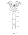
図1は、本実施形態のラケット1の平面図及び側面図である。図において左側が平面図であり右側が側面図である。図2は、ラケット1のシャフト30及びヨーク部13の拡大図である。なお、図2では説明の都合上、縦ストリング12aに番号(括弧内の数字)を付している。また、図3A〜図3Cは、図2の各位置における断面図である。図3Aは、図2のA−A断面であり、図3Bは、図2のB−B断面であり、図3Cは、図2のC−C断面である。
=== Embodiments ===
<Structure of racket>
FIG. 1 is a plan view and a side view of a
図1に示すように、ラケット1は、ボールを打つ部位であるヘッド10と、プレイヤーがラケット1を把持する部位であるグリップ20と、ヘッド10とグリップ20を一体に連結するシャフト30と、を有する。以下の説明では、ラケット1の長手方向のうちヘッド10が位置する側を先端側(一端側に相当)とし、グリップ20が位置する側を後端側(他端側に相当)とする。また、ラケット1の打面(打面に沿う平面)上において長手方向に直交する方向を幅方向とし、ラケット1の打面に直交する方向(すなわち、長手方向及び幅方向に直交する方向)を厚さ方向とする。
As shown in FIG. 1, the
ヘッド10は、ラケット1の長手方向に延びた楕円形状であるフレーム11と、フレーム11の内側に張設されたストリング12と、フレーム11の下部(後端部)同士を連結するヨーク部13と、を有する。フレーム11の外周面には、フレーム11の周方向に沿って溝部11aが設けられている。また、この溝部11aには、フレーム11の内周面から外周面まで貫通する貫通孔(不図示)が、フレーム11の周方向に沿って複数設けられている。さらにヨーク部13にも貫通孔が2つ形成されている。これらの貫通孔は、ストリング12を挿通するための孔である。
The
これらの複数の貫通孔を通して、フレーム11(及びヨーク部13)の内側には、ストリング12の部位である「縦ストリング12a」が長手方向に沿って(平行に)、且つ、幅方向に間隔を空けて複数本張られている。さらに、縦ストリング12aと交差するように、ストリング12の部位である「横ストリング12b」が、幅方向に沿って(平行に)、且つ、長手方向に間隔を空けて複数本張られている。こうして、ネット状の打面が形成される。なお、ストリング12を保護したり、打球時の振動を減衰したりするために、フレーム11の外周面(溝部11a)には不図示のグロメットが取り付けられている。そして、このグロメットを介してストリング12(縦ストリング12a、横ストリング12b)が折り返されている。また、ヨーク部13では、後述するグロメット60を介して縦ストリング12aが折り返されている。
Inside the frame 11 (and the yoke portion 13), a “
<シャフト30について>
シャフト30は、厚さ方向から見て、長手方向の先端側に向かって二股状に分岐している。この二股状に分岐している部位(シャフト30とフレーム11との接合部位)をスロート部40と呼ぶ。このようにシャフト30が二股状に分岐しているため、当該スロート部40には、厚さ方向に空いた開口部50が形成されている。換言すると、ラケット1は、シャフト30とフレーム11との接合部位に開口部50を有している。ただし、本実施形態のラケット1は、オープンスロートのラケット(図6参照)よりも、スロート部40、及び、開口部50の大きさが小さい。具体的には、開口部50は、縦ストリング12aが1回のみ折り返される程度の大きさである。このため、ラケット1のシャフト30を含めた外形の形状(輪郭)は、一本シャフトのラケット(図5参照)とほぼ同じになっており、これにより、撓りや捻じれも一本シャフトのラケットと同等である(後述する実施例参照)。また、本実施形態のラケット1では、開口部50を設けていることにより、一本シャフトのラケットと比べて、軽量化及び空気抵抗の軽減を図ることができる。なお、このように開口部50を設けることで軽量化した重量を、フレーム11やグリップ20に配分し、重量バランスを保つとともに、振り抜き性を高めるようにしている。
<About the
The
また、図2及び図3のC−C断面に示すように、シャフト30は、傾斜面31、頂面32、隆起部35を有している。なお、図1及び図3の各図からわかるように、本実施形態のラケット1は、厚さ方向の中央に対して、前側と後側とが対称になっている。以下、厚さ方向の一方側(ここでは前側)の構成について説明するが、他方側(後側)の構成も同じである。
Moreover, as shown to the CC cross section of FIG.2 and FIG.3, the
頂面32は、シャフト30における隆起部35から二股状の分岐部分までの厚さ方向の前側の端面である。
The
傾斜面31は、頂面32(及び隆起部35)を挟む幅方向の両側に設けられており、それぞれ幅方向の端に近づくにつれて厚さが小さくなるように形成されている。なお、左右の傾斜面31の傾きは同じであり、頂面32はシャフト30の幅方向の中央部に形成されている(図2及び図3C参照)。
The inclined surfaces 31 are provided on both sides in the width direction sandwiching the top surface 32 (and the raised portions 35), and are formed such that the thickness decreases as approaching the end in the width direction. In addition, the inclination of the
また、本実施形態のラケット1では、シャフト30はスロート部40で二股状に分岐しており、このため、図2に示すように、頂面32も二股状(2つの頂面42)に分岐している。また、頂面42の外側には傾斜面31と連続する外側傾斜面41が形成され、内側には分岐位置から内側傾斜面43が形成されている。ここで、図3Bに示すように、内側傾斜面43は外側傾斜面41よりも幅方向の長さが短く(すなわち、傾きが急であり)、幅方向における頂面42の位置は内側(開口部50側)寄りになっている。これにより、2つのスロート部40の頂面42が合流した頂面32の幅(幅方向の長さ)を小さくすることができ、さらに、頂面32の幅方向の両側に、幅の広い傾斜面31を形成できる。このように、本実施形態のラケット1では、シャフト30の頂面32の幅が小さく、さらに、頂面32の幅方向の両側に傾斜面31が形成されているため、空気抵抗の低減を図ることができる。
Further, in the
隆起部35は、頂面32と長手方向に連続するように、シャフト30の長手方向の後端側(グリップ20側)に設けられている。隆起部35は、後側に近づくにつれて厚さ方向に隆起(突出)し、且つ、幅が広がるように形成されている。このため、頂面32の幅(幅方向の長さ)は、隆起部35の長手方向の後端側(グリップ20との接合部)における幅(幅方向の長さ)よりも小さい。また、隆起部35の長手方向の先端側において、頂面32と傾斜面31との境界線が、隆起部35と傾斜面31との境界線と繋がっている。このような構成とすることにより、空気抵抗の低減を図りつつ、打球時の剛性を高めることができる。
The raised
<グロメット60について>
本実施形態のラケット1のヨーク部13(開口部50の長手方向の先端側の端部)には、グロメット60が設けられている。そして、グロメット60を介してストリング12(縦ストリング12a)が折り返されている。
<About
A
図4は、グロメット60の構成の説明図である。左上の図は正面図(左半分は断面図)であり、左下の図は側面図である。また、右側の図は、左上の図の各位置の断面図である。本実施形態ではグロメット60は、透明な材料(樹脂)で形成されている。これにより、グロメット60をヨーク部13に取り付けた際に、グロメット60を目立たなくすることができる。なお、グロメット60は、透明には限られず、例えば、半透明であってもよい。
FIG. 4 is an explanatory view of the configuration of the
グロメット60は、空洞部61aが形成された2つの筒部61と、2つの筒部61を連結し且つ筒部61内の空洞部61aに連通する帯状の基底部62と、を有する。筒部61の先端部がヨーク部13の外周面側(すなわち開口部50側)から貫通孔に通されることによって、グロメット60はヨーク部13に取り付けられる。なお、グロメット60は左右対称であり、グロメット60がヨーク部13に取り付けられたとき、グロメット60の幅方向の中心位置は、フレーム11の幅方向の中心位置に揃っている(図2参照)。
The
また、グロメット60の基底部62は、底部62a、一対の側壁部62b、溝部62cを有している。
The
底部62aは、2つの筒部61が設けられている部位であり、各筒部61の空洞部61aと連通する開口が形成されている。
The
一対の側壁部62bは、底部62aの厚さ方向の両端において、幅方向に沿って長手方向後端側に突出するように設けられている。なお、図4及び図3Aに示すように、一対の側壁部62bの外側は、グロメット60がヨーク部13に取り付けられた際に、ヨーク部13と一体となるような曲線形状に形成されている。これにより、打球時の空気抵抗を低減させることができる。これに対し、一対の側壁部62bの内側は直線形状に形成されている。これにより、ストリング12(縦ストリング12a)を確実に挟むことができ、位置がずれないようにできる。
The pair of
溝部62cは、ストリング12(縦ストリング12a)を折り返す部位であり、一対の側壁部62bの間において幅方向に沿って形成されている。なお、図に示すように溝部62cの大きさは一定ではなく、2つの筒部61の中間点(A−A断面の位置)では筒部61の位置(B−B断面の位置)よりも溝部62cが小さくなるように形成されている。
The
図2に示すように、グロメット60には、打面に形成された複数本の縦ストリング12aのうち、最も幅方向の中央寄りの2つの縦ストリング12aが通される。すなわち、図2の中央に対して左側の縦ストリング12a(1)と、右側の縦ストリング12a(2)は、開口部50においてグロメット60を介して(グロメット60の一方の空洞部61a、溝部62c、他方の空洞部61aを通って)折り返されている。
As shown in FIG. 2, two
一方、縦ストリング12a(1)に対して左側(外側)に隣接する縦ストリング12a(3)、及び、縦ストリング12a(2)に対して右側(外側)に隣接する縦ストリング12a(4)は、図のようにフレーム11の外周面で(不図示のグロメットを介して)折り返されている。なお、縦ストリング12a(1)、縦ストリング12a(2)、縦ストリング12a(3)、縦ストリング12a(4)は、それぞれ、第1縦ストリング、第2縦ストリング、第3縦ストリング、第4縦ストリングに相当する。
On the other hand, the
以上説明したように、本実施形態のラケット1は、スロート部40(シャフト30とフレーム11との接合部位)に開口部50を有している。ただし、本実施形態のラケット1では、スロート部40、及び、開口部50の大きさが小さく、開口部50において縦ストリング12aが1回のみ折り返される。これにより、一本シャフトの撓りや捻じれを維持しつつ、振り抜き性の向上を図ることができる。
As described above, the
<実施例>
本実施形態のラケット1と、一本シャフトのラケット100と、オープンスロートのラケット200との比較を行った。
<Example>
The
図5は、ラケット100(一本シャフト)の構成の概略説明図である。ラケット100は、打面が形成されたヘッド110と、グリップ120と、ヘッド110とグリップ120とを連結するシャフト130を有している。ラケット100は一本シャフトタイプであるので、シャフト130は二股状に分岐していない。また、シャフト30の長手方向に垂直な断面は、略矩形状である。なお、ラケット100の外形(輪郭)は、本実施形態のラケット1とほぼ同じである。
FIG. 5 is a schematic explanatory view of the configuration of the racket 100 (single shaft). The
図6は、ラケット200(オープンスロート)の構成の概略説明図である。ラケット200は、打面が形成されたヘッド210と、グリップ220と、ヘッド210とグリップ220とを連結するシャフト230を有している。ラケット200のシャフト230は、二股状に分岐しており、スロート部240が形成されている。このラケット200は、市販されているオープンスロートタイプのラケットのうち、二股部分(スロート部40)の形状が最も小さいものである。具体的には、ラケット200では、スロート部40の開口部に4本の縦ストリングが通されている(すなわち、開口部において縦ストリングの折り返しが2箇所ある)。このため、ラケット200では、開口部にグロメット(不図示)が2つ設けられており、ラケット200の幅方向の中心位置と各グロメットの幅方向の中心位置が揃っていない。
FIG. 6 is a schematic explanatory view of the configuration of the racket 200 (open throat). The
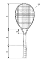
図7は、ラケット1とラケット200の寸法を比較した図である。図7の下図に示すように、シャフト長さ(長手方向の長さ)をMとし、シャフト幅(幅方向の長さ)をWとする。また、スロート部の長さ(長手方向の長さ)をMaとし、スロート部の幅をWaとする。
FIG. 7 is a view comparing dimensions of the
シャフト幅Wは、小さいほど捻じれやすくなる。図7において、ラケット200のシャフト幅Wは85mmであるのに対し、ラケット1のシャフト幅Wは76mmである。このように、ラケット1は、ラケット200よりもシャフト幅Wが小さい(つまり、ラケット1はラケット200よりも捻じれやすい)。
The smaller the shaft width W, the easier it is to twist. In FIG. 7, while the shaft width W of the
また、シャフト長さMは、大きいほど撓りやすくなる。図7において、ラケット200のシャフト長さMは140mmであるのに対し、ラケット1のシャフト長さMは181mmである。このように、ラケット1は、ラケット200よりもシャフト長さMが大きい(つまり、ラケット1はラケット200よりも撓りやすい)。
Also, the larger the shaft length M, the easier it is to bend. In FIG. 7, while the shaft length M of the
また、係数M/Waは、大きいほど撓りやすく捻じれやすくなる。図7において、ラケット200の係数M/Waは2.9であるのに対し、ラケット1の係数M/Wは5.5である。このように、ラケット1は、ラケット200よりも係数M/Wが大きい(つまりラケット1はラケット200よりも撓りやすく捻じれやすい)。
Also, as the coefficient M / Wa is larger, it becomes easier to bend and twist. In FIG. 7, while the coefficient M / Wa of the
なお、図7で表されるデータは一実施例であり、各部の大きさはこれに限られるものではない。例えば、ラケット1のシャフト長さMは170〜195(mm)、シャフト幅Wは72〜82(mm)が望ましい。また、スロート長さMaは20〜30(mm)、スロート幅Waは25〜30(mm)が望ましい。これらの範囲内において係数M/Waは4.5〜7.8であり、ラケット200の係数M/Wa(=2.9)よりも大きい。
The data shown in FIG. 7 is an example, and the size of each part is not limited to this. For example, the shaft length M of the
図8は、各ラケットの特性比較の結果を示す図である。ここでは、撓り及び捻じれによる変形率を比較している。 FIG. 8 is a diagram showing the results of characteristic comparison of the respective rackets. Here, deformation rates due to bending and twisting are compared.
図からわかるように、一本シャフトのラケット100は、オープンシャフトのラケット200と比べて、撓り及び捻じれが大きい。特に、捻じれは、ラケット200が145であるのに対し、ラケット100が173であり、ラケット100の方が大幅に大きい。
As can be seen from the figure, the single-shafted
本実施形態のラケット1は、図8に示すように、一本シャフトのラケット100と同等以上の撓り及び捻じれを実現している。さらに、ラケット1はシャフト30とフレーム11との接合部位に開口部50を有しており、ラケット100よりも軽量化及び空気抵抗の低減を図ることができる。これにより、振り抜き性の向上を図ることができる。
As shown in FIG. 8, the
===その他===
上記の実施形態は、本発明の理解を容易にするためのものであり、本発明を限定して解釈するためのものではない。本発明は、その趣旨を逸脱することなく、変更、改良され得ると共に、本発明にはその等価物が含まれることは言うまでもない。
=== Others ===
The above embodiments are for the purpose of facilitating the understanding of the present invention, and are not for the purpose of limiting the present invention. It goes without saying that the present invention can be modified and improved without departing from the gist thereof, and the present invention includes the equivalents thereof.
1 ラケット
10 ヘッド
11 フレーム
11a 溝部
12 ストリング
12a 縦ストリング
12b 横ストリング
13 ヨーク部
20 グリップ
30 シャフト
31 傾斜面
32 頂面
35 隆起部
40 スロート部
41 外側傾斜面
42 頂面
43 内側傾斜面
50 開口部
60 グロメット
61 筒部
61a 空洞部
62 基底部
62a 底部
62b 側壁部
62c 溝部
100 ラケット(一本シャフト)
110 ヘッド
120 グリップ
130 シャフト
200 ラケット(オープンスロート)
210 ヘッド
220 グリップ
230 シャフト
240 スロート部
DESCRIPTION OF
110
210
Claims (3)
前記シャフトの長手方向の一端側に接合されたフレームであって、前記長手方向に平行な縦ストリングが前記長手方向と直交する幅方向に間隔を空けて複数本張られ、且つ、前記幅方向に平行な横ストリングが前記長手方向に間隔を空けて複数本張られて打面が形成されたフレームと、
前記シャフトの前記長手方向の他端側に接合されたグリップと、
を備えたラケットであって、
前記シャフトと前記フレームとの接合部位に開口部を有し、
複数本の前記縦ストリングのうち、前記打面における前記幅方向の最も中央寄りの第1縦ストリング及び第2縦ストリングは、前記開口部で折り返されており、前記第1縦ストリングに対して外側に隣接した第3縦ストリング、及び、前記第2縦ストリングに対して外側に隣接した第4縦ストリングは、前記フレームの外周面で折り返されており、
前記シャフトは、前記長手方向及び前記幅方向と直交する厚さ方向の頂面と、前記頂面の前記幅方向の両側に設けられた傾斜面とを有し、
前記接合部位において、前記幅方向に前記開口部を挟む前記シャフトの前記頂面は、前記開口部側寄りに設けられている、
ことを特徴とするラケット。 With the shaft,
A frame joined to one end side in the longitudinal direction of the shaft, in which a plurality of longitudinal strings parallel to the longitudinal direction are stretched at intervals in the width direction orthogonal to the longitudinal direction, and in the width direction A frame in which a plurality of parallel horizontal strings are stretched at intervals in the longitudinal direction to form a striking surface;
A grip joined to the other end of the shaft in the longitudinal direction;
A racket with
It has an opening at the junction of the shaft and the frame,
Among the plurality of vertical strings, the first vertical string and the second vertical string closest to the center in the width direction in the hitting surface are folded back at the opening and are outside the first vertical string. A third vertical string adjacent to the second vertical string, and a fourth vertical string adjacent to the second vertical string outward on the outer circumferential surface of the frame ;
The shaft has a top surface in a thickness direction orthogonal to the longitudinal direction and the width direction, and sloped surfaces provided on both sides in the width direction of the top surface.
In the joint portion, the top surface of the shaft sandwiching the opening in the width direction is provided closer to the opening.
A racket characterized by
前記シャフトの長手方向の一端側に接合されたフレームであって、前記長手方向に平行な縦ストリングが前記長手方向と直交する幅方向に間隔を空けて複数本張られ、且つ、前記幅方向に平行な横ストリングが前記長手方向に間隔を空けて複数本張られて打面が形成されたフレームと、
前記シャフトの前記長手方向の他端側に接合されたグリップと、
を備えたラケットであって、
前記シャフトと前記フレームとの接合部位に開口部を有し、
複数本の前記縦ストリングのうち、前記打面における前記幅方向の最も中央寄りの第1縦ストリング及び第2縦ストリングは、前記開口部で折り返されており、前記第1縦ストリングに対して外側に隣接した第3縦ストリング、及び、前記第2縦ストリングに対して外側に隣接した第4縦ストリングは、前記フレームの外周面で折り返されており、
前記シャフトは、前記長手方向及び前記幅方向と直交する厚さ方向の頂面と、前記頂面の前記幅方向の両側に設けられた傾斜面とを有し、
前記シャフトの前記長手方向の前記他端側に、前記厚さ方向に突出するように設けられた隆起部を有し、
前記頂面の前記幅方向の長さは、前記隆起部の前記長手方向の前記他端側における前記幅方向の長さよりも小さい、
ことを特徴とするラケット。 With the shaft,
A frame joined to one end side in the longitudinal direction of the shaft, in which a plurality of longitudinal strings parallel to the longitudinal direction are stretched at intervals in the width direction orthogonal to the longitudinal direction, and in the width direction A frame in which a plurality of parallel horizontal strings are stretched at intervals in the longitudinal direction to form a striking surface;
A grip joined to the other end of the shaft in the longitudinal direction;
A racket with
It has an opening at the junction of the shaft and the frame,
Among the plurality of vertical strings, the first vertical string and the second vertical string closest to the center in the width direction in the hitting surface are folded back at the opening and are outside the first vertical string. A third vertical string adjacent to the second vertical string, and a fourth vertical string adjacent to the second vertical string outward on the outer circumferential surface of the frame;
The shaft has a top surface in a thickness direction orthogonal to the longitudinal direction and the width direction, and sloped surfaces provided on both sides in the width direction of the top surface.
The other end side in the longitudinal direction of the shaft has a protruding portion provided so as to project in the thickness direction,
The length in the width direction of the top surface is smaller than the length in the width direction at the other end side of the protrusion in the longitudinal direction,
A racket characterized by
前記傾斜面と前記頂面との境界線が、前記隆起部の前記長手方向の前記一端側において、前記隆起部と前記傾斜面との境界線と繋がっている、
ことを特徴とするラケット。 The racket according to claim 2 , wherein
A boundary line between the inclined surface and the top surface is connected to a boundary line between the raised portion and the inclined surface at the one end side in the longitudinal direction of the raised portion.
A racket characterized by
Priority Applications (1)
| Application Number | Priority Date | Filing Date | Title |
|---|---|---|---|
| JP2015113155A JP6525745B2 (en) | 2015-06-03 | 2015-06-03 | racket |
Applications Claiming Priority (1)
| Application Number | Priority Date | Filing Date | Title |
|---|---|---|---|
| JP2015113155A JP6525745B2 (en) | 2015-06-03 | 2015-06-03 | racket |
Publications (2)
| Publication Number | Publication Date |
|---|---|
| JP2016221148A JP2016221148A (en) | 2016-12-28 |
| JP6525745B2 true JP6525745B2 (en) | 2019-06-05 |
Family
ID=57745209
Family Applications (1)
| Application Number | Title | Priority Date | Filing Date |
|---|---|---|---|
| JP2015113155A Active JP6525745B2 (en) | 2015-06-03 | 2015-06-03 | racket |
Country Status (1)
| Country | Link |
|---|---|
| JP (1) | JP6525745B2 (en) |
Families Citing this family (2)
| Publication number | Priority date | Publication date | Assignee | Title |
|---|---|---|---|---|
| CN106914005A (en) * | 2017-03-11 | 2017-07-04 | 赵博 | A kind of simple sports apparatus of Multifunctional sports |
| JP7286350B2 (en) * | 2019-03-08 | 2023-06-05 | ヨネックス株式会社 | racket |
Family Cites Families (7)
| Publication number | Priority date | Publication date | Assignee | Title |
|---|---|---|---|---|
| JPS4988847U (en) * | 1972-11-18 | 1974-08-01 | ||
| JPS50108034A (en) * | 1974-01-30 | 1975-08-26 | ||
| JPS52167359U (en) * | 1977-04-04 | 1977-12-19 | ||
| JPS5626171U (en) * | 1979-08-08 | 1981-03-10 | ||
| JPH0429623Y2 (en) * | 1986-02-20 | 1992-07-17 | ||
| CA2174696A1 (en) * | 1996-04-22 | 1997-10-23 | Charles Dicerbo | Sports racket |
| JP2000189544A (en) * | 1998-12-28 | 2000-07-11 | Mizuno Corp | Badminton racket |
-
2015
- 2015-06-03 JP JP2015113155A patent/JP6525745B2/en active Active
Also Published As
| Publication number | Publication date |
|---|---|
| JP2016221148A (en) | 2016-12-28 |
Similar Documents
| Publication | Publication Date | Title |
|---|---|---|
| CN105283229B (en) | racket and grommet | |
| WO2017110327A1 (en) | Grommet and racket | |
| JP6196786B2 (en) | racket | |
| JP6525745B2 (en) | racket | |
| JP6749902B2 (en) | Badminton racket | |
| US7806789B2 (en) | Sports racket | |
| WO2009090951A1 (en) | Racket | |
| US20220134190A1 (en) | Grommet and racket | |
| US20230141640A1 (en) | Racket | |
| WO2016195037A1 (en) | Racket | |
| JP2018102454A (en) | Tennis racket frame | |
| JP6163324B2 (en) | Racket and grommet | |
| JP6782154B2 (en) | Grommets and rackets | |
| EP2805750B1 (en) | Racket | |
| US20220134191A1 (en) | Grommet and racket | |
| JP6943608B2 (en) | racket | |
| WO2022163454A1 (en) | Grommet and racket | |
| CN110709143B (en) | Racket | |
| US5642881A (en) | Tri-hollow racket with traverse ribs | |
| JP2008017951A (en) | Racket frame and racket | |
| JP6155126B2 (en) | racket | |
| JP6427406B2 (en) | Badminton racket | |
| JP6535225B2 (en) | Badminton racket | |
| GB2491113A (en) | A brace for a tennis racket throat | |
| JP2020151059A (en) | racket |
Legal Events
| Date | Code | Title | Description |
|---|---|---|---|
| A621 | Written request for application examination |
Free format text: JAPANESE INTERMEDIATE CODE: A621 Effective date: 20180518 |
|
| A977 | Report on retrieval |
Free format text: JAPANESE INTERMEDIATE CODE: A971007 Effective date: 20190117 |
|
| A131 | Notification of reasons for refusal |
Free format text: JAPANESE INTERMEDIATE CODE: A131 Effective date: 20190122 |
|
| A521 | Request for written amendment filed |
Free format text: JAPANESE INTERMEDIATE CODE: A523 Effective date: 20190318 |
|
| TRDD | Decision of grant or rejection written | ||
| A01 | Written decision to grant a patent or to grant a registration (utility model) |
Free format text: JAPANESE INTERMEDIATE CODE: A01 Effective date: 20190409 |
|
| A61 | First payment of annual fees (during grant procedure) |
Free format text: JAPANESE INTERMEDIATE CODE: A61 Effective date: 20190507 |
|
| R150 | Certificate of patent or registration of utility model |
Ref document number: 6525745 Country of ref document: JP Free format text: JAPANESE INTERMEDIATE CODE: R150 |
|
| R250 | Receipt of annual fees |
Free format text: JAPANESE INTERMEDIATE CODE: R250 |