JP6525730B2 - Mobile terminal and contactless charger - Google Patents

Mobile terminal and contactless charger Download PDF

Info

Publication number
JP6525730B2
JP6525730B2 JP2015107165A JP2015107165A JP6525730B2 JP 6525730 B2 JP6525730 B2 JP 6525730B2 JP 2015107165 A JP2015107165 A JP 2015107165A JP 2015107165 A JP2015107165 A JP 2015107165A JP 6525730 B2 JP6525730 B2 JP 6525730B2
Authority
JP
Japan
Prior art keywords
power transmission
mobile terminal
power
coil
circuit
Prior art date
Legal status (The legal status is an assumption and is not a legal conclusion. Google has not performed a legal analysis and makes no representation as to the accuracy of the status listed.)
Active
Application number
JP2015107165A
Other languages
Japanese (ja)
Other versions
JP2016226076A (en
Inventor
聡 生田
聡 生田
佐藤 直紀
直紀 佐藤
Current Assignee (The listed assignees may be inaccurate. Google has not performed a legal analysis and makes no representation or warranty as to the accuracy of the list.)
Sharp Corp
Original Assignee
Sharp Corp
Priority date (The priority date is an assumption and is not a legal conclusion. Google has not performed a legal analysis and makes no representation as to the accuracy of the date listed.)
Filing date
Publication date
Application filed by Sharp Corp filed Critical Sharp Corp
Priority to JP2015107165A priority Critical patent/JP6525730B2/en
Publication of JP2016226076A publication Critical patent/JP2016226076A/en
Application granted granted Critical
Publication of JP6525730B2 publication Critical patent/JP6525730B2/en
Active legal-status Critical Current
Anticipated expiration legal-status Critical

Links

Images

Description

本発明は、通信機能を有する移動体端末および移動体端末を充電するための無接点充電器に関する。   The present invention relates to a mobile terminal having a communication function and a non-contact charger for charging the mobile terminal.

従来、スマートフォン等の移動体端末を充電するための充電器が知られている。
たとえば、特許文献1には、このような充電器に関する発明が開示されている。具体的には、特許文献1の充電器は、移動体端末が充電中に基地局からの信号を受信した場合、移動体端末から受信動作中である旨の信号を受信する。充電器は、当該信号を受信すると、充電回路の一部または全部の動作を停止させる。これにより、移動体端末が充電中に基地局からの信号を受信した場合であっても、充電器が発生するノイズを低減できる。それゆえ、上記信号の受信品質の低下を防ぐことが可能となる。
BACKGROUND Conventionally, a charger for charging a mobile terminal such as a smartphone is known.
For example, Patent Document 1 discloses an invention related to such a charger. Specifically, when the mobile terminal receives a signal from the base station while charging, the charger of Patent Document 1 receives a signal indicating that reception operation is in progress from the mobile terminal. When the charger receives the signal, the charger stops operation of part or all of the charging circuit. Thereby, even if the mobile terminal receives a signal from the base station while charging, it is possible to reduce the noise generated by the charger. Therefore, it is possible to prevent the deterioration of the reception quality of the signal.

また、従来、移動体端末をワイヤレスで充電する無接点充電器が知られている。   Also, conventionally, a non-contact charger for charging a mobile terminal wirelessly is known.

特開2008−131812号公報JP, 2008-131812, A

しかしながら、特許文献1の充電器は、充電回路の一部または全部の動作を停止させるため、充電回路の動作を停止しない構成(すなわち、充電を中断しない構成)に比べて、移動体端末の充電に要する時間が長くなってしまう。   However, the charger of Patent Document 1 charges the mobile terminal compared with the configuration in which the operation of the charging circuit is not stopped (ie, the configuration in which the charging is not interrupted) in order to stop the operation of part or all of the charging circuit. The time required for

本願発明は、上記の問題点に鑑みなされたものであって、その目的は、充電中であっても基地局等の通信機器から送られてくる信号の受信品質の低下を軽減可能な移動体端末、および無接点充電器を提供することにある。   The present invention has been made in view of the above problems, and an object thereof is a mobile body capable of reducing deterioration in reception quality of a signal transmitted from a communication device such as a base station even during charging. A terminal, and providing a non-contact charger.

本発明のある局面に従うと、移動体端末は、無接点充電器によって充電される。無接点充電器は、複数の送電回路と、複数の送電回路によって共用されるとともに複数の送電回路のうちから選択された1つの送電回路から電力の供給を受ける送電用のコイルとを有している。移動体端末は、充電が可能なバッテリと、移動体端末と通信可能な通信機器から送信される電波の受信品質を検出する検出部と、移動体端末が無接点充電器に載置されている状態でコイルに対して複数の送電回路の各々から個別に電力が供給されたことに基づき、複数の送電回路のうちから、受信品質が最も高くなったときにコイルに対して電力を供給していた送電回路を特定する特定部とを備える。移動体端末は、特定が行われた後は、コイルに対する電力を特定された送電回路に供給させる。   According to one aspect of the invention, the mobile terminal is charged by the contactless charger. The non-contact charger has a plurality of power transmission circuits, and a coil for power transmission which is shared by the plurality of power transmission circuits and receives power supply from one of the plurality of power transmission circuits. There is. The mobile terminal includes a battery that can be charged, a detection unit that detects the reception quality of radio waves transmitted from a communication device that can communicate with the mobile terminal, and the mobile terminal is mounted on the noncontact charger. Power is supplied to the coil when the reception quality is highest among the plurality of power transmission circuits based on power being individually supplied to each of the plurality of power transmission circuits to the coil in the state And a specifying unit for specifying the power transmission circuit. After identification, the mobile terminal supplies power to the coil to the identified transmission circuit.

本発明によれば、充電中であっても基地局等の通信機器から送られてくる信号の受信品質の低下を軽減可能となる。   According to the present invention, it is possible to reduce deterioration in reception quality of a signal transmitted from a communication device such as a base station even during charging.

本発明の実施の形態1に係る無接点充電器1の使用方法を示す平面図である。It is a top view which shows the usage method of the non-contact charger 1 which concerns on Embodiment 1 of this invention. 無接点充電器1のハードウェア構成を表したブロック図である。It is a block diagram showing the hardware constitutions of the non-contact charger 1. 移動体端末2の機能的構成およびハードウェア構成を説明するためのブロック図である。FIG. 2 is a block diagram for explaining a functional configuration and a hardware configuration of a mobile terminal 2; 移動体端末2における処理の流れを説明するためのフローチャートである。5 is a flowchart for explaining the flow of processing in the mobile terminal 2; 本発明の実施の形態2に係る無接点充電器1Aの使用方法を示す平面図である。It is a top view which shows the usage method of the non-contact charger 1A which concerns on Embodiment 2 of this invention. 無接点充電器1Aのハードウェア構成を表したブロック図である。It is a block diagram showing the hardware constitutions of non-contact charger 1A. 無接点充電器1Aにおける処理の流れを説明するためのフローチャートである。It is a flowchart for demonstrating the flow of the process in the non-contact charger 1A. 無接点充電器1Aの処理の流れを説明するためのフローチャートである。It is a flowchart for demonstrating the flow of a process of the non-contact charger 1A. 移動体端末2の処理の流れを説明するためのフローチャートである。5 is a flowchart for explaining the flow of processing of the mobile terminal 2;

以下、図面を参照しつつ、本発明の各実施の形態に係る、移動体端末および無接点充電器(非接触充電器)について説明する。また、以下の説明では、同一の部材には同一の参照符号を付してある。それらの名称および機能も同じである。したがって、それらについての詳細な説明は繰り返さない。   A mobile terminal and a non-contact charger (non-contact charger) according to the embodiments of the present invention will be described below with reference to the drawings. Moreover, in the following description, the same reference numerals are given to the same members. Their names and functions are also the same. Therefore, detailed description about them will not be repeated.

なお、移動体端末としては、たとえば、スマートフォン、フィーチャーフォン、タブレット端末、ファブレット端末が挙げられる。なお、移動体端末は、これらに限定されず、通信機能と充電可能なバッテリ(二次電池)とを有するものであればよい。   In addition, as a mobile terminal, a smart phone, a feature phone, a tablet terminal, a Fablet terminal is mentioned, for example. In addition, a mobile terminal is not limited to these, What is necessary is just to have a communication function and a rechargeable battery (secondary battery).

また、以下では、移動体端末は、通信可能な相手の通信機器の一例として、基地局(典型的には、当該移動体端末が在圏する基地局)と通信するように構成されているものとする。   Also, in the following, the mobile terminal is configured to communicate with a base station (typically, a base station in which the mobile terminal is located) as an example of a communication device with which communication is possible. I assume.

[実施の形態1]
図1は、本実施の形態に係る無接点充電器1の使用方法を示す平面図である。図1を参照して、無接点充電器1は、複数の送電回路111,112,113,114と、コイル120と、プラグ130とを備えている。
First Embodiment
FIG. 1 is a plan view showing a method of using the non-contact charger 1 according to the present embodiment. Referring to FIG. 1, non-contact charger 1 includes a plurality of power transmission circuits 111, 112, 113 and 114, a coil 120 and a plug 130.

複数の送電回路111〜114は、無接点充電器1の筐体100内に備えられている。複数の送電回路111〜114は、コイル120に接続されており、コイル120に電力を供給する。また、無接点充電器1は、複数の送電回路111〜114に対して順番を表す識別番号を対応付けることにより、これらの複数の送電回路111〜114を管理している。以下では、一例として、無接点充電器1が、送電回路111を1番目の送電回路、送電回路112を2番目の送電回路、送電回路113を3番目の送電回路、送電回路114を4番目の送電回路として管理しているものとして説明する。   The plurality of power transmission circuits 111 to 114 are provided in the housing 100 of the non-contact charger 1. The plurality of power transmission circuits 111 to 114 are connected to the coil 120 and supply power to the coil 120. Moreover, the non-contact charger 1 manages the plurality of power transmission circuits 111 to 114 by associating the plurality of power transmission circuits 111 to 114 with identification numbers indicating the order. In the following, as an example, the non-contact charger 1 includes the power transmission circuit 111 as a first power transmission circuit, the power transmission circuit 112 as a second power transmission circuit, the power transmission circuit 113 as a third power transmission circuit, and the power transmission circuit 114 as a fourth. It demonstrates as what is managed as a power transmission circuit.

コイル120は、複数の送電回路111〜114によって共用される。コイル120は、筐体100の主面140に載置された移動体端末2に対して、電力を送信する。また、コイル120は、主面140に載置された移動体端末2から送られてくる信号を受信する。   The coil 120 is shared by the plurality of power transmission circuits 111 to 114. The coil 120 transmits power to the mobile terminal 2 placed on the main surface 140 of the housing 100. In addition, coil 120 receives a signal transmitted from mobile terminal 2 placed on main surface 140.

プラグ130は、建物に備え付けられた商用交流電源のコンセントに接続される。プラグ130によって、筐体100内の各部に電力が供給される。   The plug 130 is connected to a commercial AC power outlet provided in a building. The plug 130 supplies power to each part in the housing 100.

移動体端末2は、筐体100の主面140に載置されることによって、無接点充電器1によって充電される。詳しくは、移動体端末2のバッテリ260(図3参照)は、コイル120から送信される電力によって充電される。また、移動体端末2は、基地局との通信に用いるアンテナ290を有する。   The mobile terminal 2 is charged by the non-contact charger 1 by being placed on the main surface 140 of the housing 100. Specifically, the battery 260 (see FIG. 3) of the mobile terminal 2 is charged by the power transmitted from the coil 120. The mobile terminal 2 also has an antenna 290 used for communication with the base station.

詳細については後述するが、無接点充電器1は、複数の送電回路111〜114のうちのいずれか1つの送電回路を選択的に駆動させることができる。たとえば、ある局面においては、無接点充電器1は送電回路111を駆動し、他の局面においては、無接点充電器1は、複数の送電回路112〜114のいずれかを駆動する。すなわち、コイル120は、複数の送電回路111〜114のうちから選択された1つの送電回路から電力の供給を受ける。   Although the details will be described later, the non-contact charger 1 can selectively drive any one of the plurality of power transmission circuits 111 to 114. For example, in one aspect, the non-contact charger 1 drives the power transmission circuit 111, and in the other aspect, the non-contact charger 1 drives any of the plurality of power transmission circuits 112-114. That is, coil 120 receives supply of power from one of the plurality of power transmission circuits 111 to 114 selected from the power transmission circuits.

ところで、図1の状態では、移動体端末2のアンテナ290は、ノイズの発生源である送電回路114の近くに位置することになる。このような状態で、仮に、送電回路114がコイル120に電力を供給すると、移動体端末2における基地局からの信号の受信品質が低下してしまう。そのため、図1の状態では、移動体端末2の充電のために、送電回路114を使用(駆動)することは好ましくない。移動体端末2の充電のためには、送電回路114よりも他の送電回路111〜113を使用することが好ましい。   By the way, in the state of FIG. 1, the antenna 290 of the mobile terminal 2 is located near the power transmission circuit 114 which is a generation source of noise. In such a state, if the power transmission circuit 114 supplies power to the coil 120, the reception quality of the signal from the base station in the mobile terminal 2 is degraded. Therefore, in the state of FIG. 1, it is not preferable to use (drive) the power transmission circuit 114 for charging the mobile terminal 2. For charging of the mobile terminal 2, it is preferable to use other power transmission circuits 111 to 113 than the power transmission circuit 114.

より詳しくは、移動体端末2は、複数の送電回路111〜114のうち基地局から送られてくる信号の受信品質が最も良くなる(すなわち、信号の劣化が最も少ない)送電回路からコイル120に電力が供給されている状態で、充電されることが望ましい。換言すれば、無接点充電器1は、移動体端末2における受信品質が最も良くなる送電回路を駆動することが望ましい。以下では、このような構成を実現するための構成について、具体例を挙げて説明する。   More specifically, the mobile terminal 2 receives the signal received from the base station among the plurality of power transmission circuits 111 to 114 with the best reception quality (that is, the least degradation of the signal) from the power transmission circuit to the coil 120. It is desirable to be charged while power is supplied. In other words, it is desirable that the non-contact charger 1 drive a power transmission circuit that provides the best reception quality at the mobile terminal 2. Hereinafter, a configuration for realizing such a configuration will be described with a specific example.

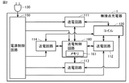
図2は、無接点充電器1のハードウェア構成を表したブロック図である。図2を参照して、無接点充電器1は、複数の送電回路111〜114と、コイル120と、プラグ130と、電源制御回路150と、送電制御回路160とを備える。送電制御回路160は、メモリ161を有している。   FIG. 2 is a block diagram showing a hardware configuration of the non-contact charger 1. Referring to FIG. 2, the noncontact charger 1 includes a plurality of power transmission circuits 111 to 114, a coil 120, a plug 130, a power control circuit 150, and a power transmission control circuit 160. The power transmission control circuit 160 has a memory 161.

電源制御回路150は、商用交流電源からプラグ130を介して供給される商用周波数の交流電力を直流電力に変換する。電源制御回路150は、複数の送電回路111〜114に、直流電力を供給する。また、電源制御回路150は、送電制御回路160にも直流電力を供給する。   The power supply control circuit 150 converts AC power of a commercial frequency supplied from a commercial AC power supply through the plug 130 into DC power. The power supply control circuit 150 supplies DC power to the plurality of power transmission circuits 111 to 114. The power supply control circuit 150 also supplies DC power to the power transmission control circuit 160.

送電制御回路160は、複数の送電回路111〜114に接続されている。送電制御回路160は、複数の送電回路111〜114の各々を個別に駆動させる制御を行なう。すなわち、送電制御回路160は、複数の送電回路111〜114のうちの1つの送電回路(たとえば、ある局面では送電回路111)のみを駆動させる。   The power transmission control circuit 160 is connected to the plurality of power transmission circuits 111 to 114. The power transmission control circuit 160 performs control to drive each of the plurality of power transmission circuits 111 to 114 individually. That is, the power transmission control circuit 160 drives only one of the plurality of power transmission circuits 111 to 114 (for example, the power transmission circuit 111 in one aspect).

送電制御回路160は、典型的には、移動体端末2からの制御命令に基づき、駆動させる送電回路を決定する。ただし、これに限定されず、送電制御回路160は、駆動させる送電回路を自身で決定してもよい。   The power transmission control circuit 160 typically determines a power transmission circuit to be driven based on a control command from the mobile terminal 2. However, the present invention is not limited to this, and the power transmission control circuit 160 may determine the power transmission circuit to be driven by itself.

送電制御回路160のメモリ161には、移動体端末2から送信されてきたデータ(たえば、制御命令)が、駆動している送電回路を介して格納される。また、詳細については後述するが、メモリ161には、移動体端末2において測定された受信品質が、送電回路111〜114毎に対応付けて格納されてもよい。   Data (for example, control instruction) transmitted from the mobile terminal 2 is stored in the memory 161 of the power transmission control circuit 160 via the power transmission circuit being driven. In addition, although the details will be described later, the reception quality measured in the mobile terminal 2 may be stored in the memory 161 in association with each of the power transmission circuits 111 to 114.

図3は、移動体端末2の機能的構成およびハードウェア構成を説明するためのブロック図である。図3を参照して、移動体端末2は、制御部210と、記憶部220と、コイル230と、受電回路240と、充電回路250と、バッテリ260と、電源制御回路270と、通信処理部280と、アンテナ290とを備える。制御部210は、検出部211と、特定部212とを含む。   FIG. 3 is a block diagram for explaining the functional configuration and hardware configuration of the mobile terminal 2. Referring to FIG. 3, mobile terminal 2 includes control unit 210, storage unit 220, coil 230, power reception circuit 240, charging circuit 250, battery 260, power control circuit 270, and communication processing unit. 280 and an antenna 290. The control unit 210 includes a detection unit 211 and a specification unit 212.

制御部210は、典型的には、移動体端末2のCPUが、オペレーションシステム上で各種のプログラムを実行することにより実現される。記憶部220は、典型的には、ROM(Read Only Memory)、RAM(Random Access Memory)、フラッシュメモリ等により構成される。通信処理部280は、通信IF(Inter Face)であって、典型的には、ベースバンド回路、RF(Radio Frequency)回路等により構成される。以下、各部の機能について説明する。   The control unit 210 is typically realized by the CPU of the mobile terminal 2 executing various programs on the operation system. The storage unit 220 is typically configured by a read only memory (ROM), a random access memory (RAM), a flash memory, or the like. The communication processing unit 280 is a communication IF (Inter Face), and typically includes a baseband circuit, an RF (Radio Frequency) circuit, and the like. The functions of each part will be described below.

制御部210は、移動体端末2の全体の動作を制御する。記憶部220は、オペレーションシステム、各種のアプリケーションプログラム、データを格納しており、制御部210によって、データの書き込みおよびデータの読み出しが行われる。   The controller 210 controls the overall operation of the mobile terminal 2. The storage unit 220 stores an operation system, various application programs, and data, and the control unit 210 writes data and reads data.

通信処理部280は、制御部210からの命令に基づき、アンテナ290を介して、データを基地局に送信する。また、通信処理部280は、アンテナ290を介して受信したデータを制御部210に送る。   The communication processing unit 280 transmits data to the base station via the antenna 290 based on the command from the control unit 210. Also, the communication processing unit 280 sends the data received via the antenna 290 to the control unit 210.

電源制御回路270は、バッテリ260に蓄えられた電力(正確には電荷)を、移動体端末2内の各ブロックに供給する。   The power supply control circuit 270 supplies the power (precisely, the charge) stored in the battery 260 to each block in the mobile terminal 2.

受電回路240は、充電回路250と、コイル230とに接続されている。受電回路240は、コイル230を介して、無接点充電器1から送信されてくる電力を受電する。詳しくは、受電回路240は、コイル230を用いて、無接点充電器1のいずれかの送電回路が駆動されることによってコイル120から送電された電力を受電する。受電回路240は、受信した電力を充電回路250に送る。正確には、受電回路240は、無接点充電器1のコイル120を1次コイル、移動体端末2のコイル230を2次コイルとした電磁誘導によって発生した誘導起電力(誘導電流)を充電回路250に送る。   The power receiving circuit 240 is connected to the charging circuit 250 and the coil 230. The power receiving circuit 240 receives power transmitted from the non-contact charger 1 via the coil 230. Specifically, the power reception circuit 240 receives power transmitted from the coil 120 by driving any power transmission circuit of the non-contact charger 1 using the coil 230. The power receiving circuit 240 sends the received power to the charging circuit 250. More precisely, the power receiving circuit 240 charges the induced electromotive force (induced current) generated by electromagnetic induction with the coil 120 of the non-contact charger 1 as the primary coil and the coil 230 of the mobile terminal 2 as the secondary coil. Send to 250.

充電回路250は、受電回路240から送られてきた誘導起電力によって、バッテリ260を充電する。   The charging circuit 250 charges the battery 260 by the induced electromotive force sent from the power receiving circuit 240.

移動体端末2が、無接点充電器1に対して、制御命令等のデータを送信する場合には、受電回路240およびコイル230を用いる。具体的には、制御部210が、送信するデータを受電回路240に送り、受電回路240がコイル230を介して無接点充電器1に当該データを送信する。   When the mobile terminal 2 transmits data such as a control command to the non-contact charger 1, the power reception circuit 240 and the coil 230 are used. Specifically, the control unit 210 sends the data to be transmitted to the power receiving circuit 240, and the power receiving circuit 240 transmits the data to the non-contact charger 1 via the coil 230.

次に、制御部210における検出部211と特定部212とについて説明する。
検出部211は、基地局から送信される電波の受信品質を検出(測定)する。
Next, the detection unit 211 and the identification unit 212 in the control unit 210 will be described.
The detection unit 211 detects (measures) the reception quality of the radio wave transmitted from the base station.

特定部212は、移動体端末2が無接点充電器1に載置されている状態でコイル120に対して複数の送電回路111〜114の各々から個別に電力が供給されたことに基づき、複数の送電回路111〜114のうちから、受信品質が最も高くなったときにコイル120に対して電力を供給していた送電回路を特定する。   A plurality of identification units 212 are provided based on the power supplied individually from each of the plurality of power transmission circuits 111 to 114 to the coil 120 in a state where the mobile terminal 2 is mounted on the non-contact charger 1. Among the power transmission circuits 111 to 114, the power transmission circuit that supplies power to the coil 120 when the reception quality is the highest is specified.

移動体端末2は、上記特定が行われた後は、コイル120に対する電力を上記特定された送電回路に供給させる。詳しくは、移動体端末2の制御部210は、無接点充電器1に制御命令を送信することによって、受信品質が最も高くなったときにコイル120に対して電力を供給していた送電回路を駆動させるための制御を行なう。   After the identification is performed, the mobile terminal 2 supplies power to the coil 120 to the identified transmission circuit. Specifically, the control unit 210 of the mobile terminal 2 transmits a control command to the non-contact charger 1 to transmit power to the coil 120 when the reception quality becomes the highest. Control for driving is performed.

このような処理により、移動体端末2は、複数の送電回路111〜114のうち受信品質が最も高い(すなわち、受信品質の劣化が最も少ない)送電回路を用いて、バッテリ260を充電することが可能となる。それゆえ、移動体端末2は、充電中であっても基地局から送られてくる信号の受信品質の低下を軽減することが可能となる。その結果、移動体端末2は、途中で充電を中断しなくてもよくなる。よって、移動体端末2は、受信品質の低下を軽減することにより、途中で充電を中断するような従来の構成に比べて充電時間を短縮することが可能となる。   By such processing, the mobile terminal 2 can charge the battery 260 using the power transmission circuit having the highest reception quality (that is, the least deterioration in reception quality) among the plurality of power transmission circuits 111 to 114. It becomes possible. Therefore, the mobile terminal 2 can reduce deterioration in the reception quality of the signal transmitted from the base station even during charging. As a result, the mobile terminal 2 does not have to interrupt charging halfway. Therefore, the mobile terminal 2 can shorten the charging time as compared with the conventional configuration in which the charging is interrupted halfway by reducing the deterioration of the reception quality.

なお、上記においては、無接点充電器1の充電方式として、電磁誘導方式を例に挙げて説明したが、これに限定されるものではない。充電方式は、たとえば、電波受信方式、磁界共鳴方式であってもよい。   In addition, in the above, although the electromagnetic induction system was mentioned as an example and demonstrated as a charge system of the non-contact charger 1, it is not limited to this. The charging method may be, for example, a radio wave receiving method or a magnetic field resonance method.

図4は、移動体端末2における処理の流れを説明するためのフローチャートである。図4を参照して、ステップS2において、移動体端末2(詳しくは、CPU)は、移動体端末2が無接点充電器1(詳しくは、主面140)に載置されているか否かを判断する。   FIG. 4 is a flowchart for explaining the flow of processing in the mobile terminal 2. Referring to FIG. 4, in step S2, mobile terminal 2 (specifically, the CPU) determines whether mobile terminal 2 is placed on non-contact charger 1 (specifically, main surface 140). to decide.

具体的には、送電制御回路160は、間欠的にコイル120に交流電流を供給することによってコイル120を励磁する。これにより、コイル120から電波が送信される。受電回路240は、前述の電波を受信したとき、コイル230に負荷を接続した接続状態と、コイル230に負荷を接続しない非接続状態との間で切替処理を行なう。当該接続状態にあるときには、コイル230と磁気結合するコイル120から見たインピーダンスが非接続状態のときよりも増加する。それゆえ、コイル120に供給される電流が変化する。送電制御回路160は、当該電流の変化を通じて主面140に移動端末帯2が載置されているか否かを判断する。以上により、移動体端末2は、無接点充電器1に載置されているか否かを判断することができる。   Specifically, the power transmission control circuit 160 excites the coil 120 by intermittently supplying an alternating current to the coil 120. Thus, radio waves are transmitted from the coil 120. When receiving the above-described radio wave, the power reception circuit 240 performs switching processing between a connected state in which a load is connected to the coil 230 and a disconnected state in which the load is not connected to the coil 230. When in the connected state, the impedance seen from the coil 120 magnetically coupled to the coil 230 is higher than that in the unconnected state. Therefore, the current supplied to the coil 120 changes. The power transmission control circuit 160 determines whether the mobile terminal band 2 is placed on the main surface 140 through the change of the current. From the above, it can be determined whether the mobile terminal 2 is placed on the non-contact charger 1 or not.

ステップS4において、移動体端末2は、送電回路の個数(n)を無接点充電器1から取得する。たとえば、移動体端末2は、無接点充電器1から「n=4」との情報を取得する。なお、移動体端末2が予め当該個数を記憶している場合、当該取得処理は不要である。   In step S4, the mobile terminal 2 obtains the number (n) of power transmission circuits from the non-contact charger 1. For example, the mobile terminal 2 acquires information “n = 4” from the non-contact charger 1. In addition, when the mobile terminal 2 stores the said number in advance, the said acquisition process is unnecessary.

ステップS6において、移動体端末2は、基地局から送られてくる電波を受信可能であるか否かを判断する。具体的には、移動体端末2は、基地局から送られてくる電波の受信品質が、予め定められた値以上か否かを判断する。   In step S6, the mobile terminal 2 determines whether it can receive the radio wave transmitted from the base station. Specifically, the mobile terminal 2 determines whether the reception quality of the radio wave transmitted from the base station is equal to or more than a predetermined value.

移動体端末2は、基地局からの電波を受信不能であると判断した場合(ステップS6においてNO)、ステップS24において、複数の送電回路111〜114のうち所定の送電回路を駆動させることによって、バッテリ260を充電する。たとえば、移動体端末2は、駆動させる送電回路を特定するための通知を無接点充電器1に送信することによって当該送電回路を駆動させてもよい。   When the mobile terminal 2 determines that the radio wave from the base station can not be received (NO in step S6), in step S24, by driving a predetermined power transmission circuit among the plurality of power transmission circuits 111 to 114, The battery 260 is charged. For example, the mobile terminal 2 may drive the power transmission circuit by transmitting a notification for specifying the power transmission circuit to be driven to the non-contact charger 1.

あるいは、移動体端末2が所定の通知を無接点充電器1に送ることにより、無接点充電器1が駆動する送電回路を決定(選択)してもよい。たとえば、無接点充電器1は、複数の送電回路111〜114のうち、メモリ161に予め記憶されている番号の送電回路(典型的には、デフォルトの送電回路)を駆動してもよい。   Alternatively, the mobile terminal 2 may determine (select) the power transmission circuit to be driven by the non-contact charger 1 by sending a predetermined notification to the non-contact charger 1. For example, the non-contact charger 1 may drive a power transmission circuit (typically, a default power transmission circuit) of a number stored in advance in the memory 161 among the plurality of power transmission circuits 111 to 114.

移動体端末2は、基地局からの電波を受信可能であると判断した場合(ステップS6においてYES)、ステップS8において、予め規定された変数kの値を1とする。ステップS10において、移動体端末2は、k番目の送電回路のみを駆動させるための通知(典型的には、制御命令)を、無接点充電器1に対して送信する。   When the mobile terminal 2 determines that the radio wave from the base station can be received (YES in step S6), the value of the variable k defined in advance is set to 1 in step S8. In step S10, the mobile terminal 2 transmits, to the contactless charger 1, a notification (typically, a control command) for driving only the k-th power transmission circuit.

ステップS12において、移動体端末2は、基地局からの電波の受信品質(Sk)を検出する。ステップS14において、移動体端末2は、Skが閾値Sth以上であるか否かを判断する。閾値Sth以上であると判断された場合(ステップS14においてYES)、ステップS26において、k番目の送電回路を駆動させるための通知(典型的には、制御命令)を無接点充電器1に対して送信することによって、バッテリ260を充電する。   In step S12, the mobile terminal 2 detects the reception quality (Sk) of the radio wave from the base station. In step S14, the mobile terminal 2 determines whether Sk is equal to or greater than a threshold Sth. If it is determined that the threshold is equal to or greater than Sth (YES in step S14), in step S26, a notification (typically, a control instruction) for driving the kth power transmission circuit is sent to non-contact charger 1 By transmitting, the battery 260 is charged.

閾値Sth以上ではないと判断された場合(ステップS14においてNO)、ステップS16において、移動体端末2は、変数kの値をインクリメントする。すなわち、移動体端末2は、変数kの値を1だけ増加させる。ステップS18において、移動体端末2は、変数kの値が、無接点充電器1における送電回路の個数(n)よりも大きいか否かを判断する。kがn以下であると判断された場合(ステップS18においてNO)、移動体端末2は、処理をステップS10に戻す。   If it is determined that it is not the threshold Sth or more (NO in step S14), the mobile terminal 2 increments the value of the variable k in step S16. That is, the mobile terminal 2 increases the value of the variable k by one. In step S18, the mobile terminal 2 determines whether the value of the variable k is larger than the number (n) of power transmission circuits in the non-contact charger 1. If it is determined that k is n or less (NO in step S18), the mobile terminal 2 returns the process to step S10.

kがnよりも大きいと判断された場合(ステップS18においてYES)、ステップS20において、移動体端末2は、受信品質S1,…,Snにおける最大値を得たときの送電回路を特定する。すなわち、移動体端末2は、受信品質が最も高くなったときにコイル120に対して電力を供給していた送電回路を特定する。つまり、移動体端末2は、充電に用いる送電回路を特定する。   If k is determined to be larger than n (YES in step S18), in step S20, the mobile terminal 2 specifies a power transmission circuit when the maximum value of the reception quality S1, ..., Sn is obtained. That is, the mobile terminal 2 specifies the power transmission circuit that has supplied power to the coil 120 when the reception quality is the highest. That is, the mobile terminal 2 specifies a power transmission circuit used for charging.

ステップS22において、移動体端末2は、特定された送電回路のみを駆動させるための通知を、無接点充電器1に対して送信する。詳しくは、移動体端末2は、上記特定が行われたことに基づき、受信品質が最も高くなったときに電力を供給していた送電回路に電力を再度供給させるための通知を、無接点充電器1に対して送信する。これにより、移動体端末2は、以後、特定された送電回路の駆動によって発生する電力によって、バッテリ260を充電することが可能となる。   In step S22, the mobile terminal 2 transmits, to the contactless charger 1, a notification for driving only the specified power transmission circuit. Specifically, based on the above specification, the mobile terminal 2 performs contactless charging for notifying again the power to the power transmission circuit that has supplied power when the reception quality is the highest. It sends to the device 1. As a result, the mobile terminal 2 can charge the battery 260 with the power generated by driving of the specified power transmission circuit thereafter.

<小括>
(1)以上のように、移動体端末2は、(i)移動体端末2と通信可能な基地局(通信機器)から送信される電波の受信品質を検出する検出部211と、(ii)移動体端末2が無接点充電器1に載置されている状態でコイル120に対して複数の送電回路111〜114の各々から個別に電力が供給されたことに基づき、複数の送電回路111〜114のうちから、受信品質が最も高くなったときにコイル120に対して電力を供給していた送電回路を特定する特定部212とを備える。移動体端末2は、上記特定が行われた後は、コイル120に対する電力を上記特定された送電回路から供給させる。
<Summary>
(1) As described above, the mobile terminal 2 (i) detects the reception quality of the radio wave transmitted from the base station (communication device) capable of communicating with the mobile terminal 2; (ii) In the state where the mobile terminal 2 is mounted on the non-contact charger 1, the plurality of power transmission circuits 111 to 111 are individually supplied with power from the plurality of power transmission circuits 111 to 114 individually to the coil 120. Among them, the identification unit 212 identifies the power transmission circuit that has supplied power to the coil 120 when the reception quality is the highest. After the identification is performed, the mobile terminal 2 supplies power to the coil 120 from the identified transmission circuit.

当該構成によれば、充電中であっても基地局等の通信機器から送られてくる信号の受信品質の低下を軽減することが可能となる。その結果、移動体端末2は、途中で充電を中断しなくてもよくなる。よって、移動体端末2は、受信品質の低下を軽減するために途中で充電を中断するような従来の構成に比べて、充電時間を短縮することが可能となる。   According to the configuration, it is possible to reduce deterioration in reception quality of a signal transmitted from a communication device such as a base station even during charging. As a result, the mobile terminal 2 does not have to interrupt charging halfway. Therefore, the mobile terminal 2 can shorten the charging time as compared with the conventional configuration in which the charging is interrupted halfway to reduce the deterioration of the reception quality.

(2)詳しくは、移動体端末2は、上記特定を行なうために、複数の送電回路111〜114の各々から個別に電力を供給させるための通知(第1の通知)を、無接点充電器1に対して送信する。移動体端末2は、上記特定が行われたことに基づき、受信品質が最も高くなったときに電力を供給していた送電回路に電力を再度供給させるための通知(第2の通知)を、無接点充電器1に対して送信する。   (2) In detail, the mobile terminal 2 uses the non-contact charger to send a notification (first notification) for individually supplying power from each of the plurality of power transmission circuits 111 to 114 in order to perform the above identification. Send to 1 The mobile terminal 2 makes a notification (second notification) for causing the power transmission circuit that has supplied the power to be supplied again when the reception quality is the highest, based on the above specification being performed, Transmit to the non-contact charger 1.

(3)図4におけるステップS14の処理に着目すると以下のとおりである。特定部212は、コイル120に対して最後の順の送電回路(たとえば、4番目の送電回路)から電力が供給されるまでに予め定められた値(閾値Sth)以上の受信品質が検出されていないことを条件に、上位特定を行なう。移動体端末2は、予め定められた値以上の受信品質が検出された後には、コイル120に対する電力を、予め定められた値以上の受信品質が検出されたときにコイル120に対して電力を供給していた送電回路に供給させる。   (3) Focusing on the process of step S14 in FIG. The identification unit 212 detects reception quality equal to or greater than a predetermined value (threshold value Sth) before power is supplied to the coil 120 from the power transmission circuit (for example, the fourth power transmission circuit) in the final order. The upper rank specification is performed on the condition that there is no. After the mobile terminal 2 detects a reception quality equal to or greater than a predetermined value, the power to the coil 120 is detected when the reception quality equal to or higher than a predetermined value is detected. Supply to the power transmission circuit that was supplying.

最後の順の送電回路(たとえば、送電回路114)に電力を供給させる前に予め定められた値以上の受信品質が検出された場合には、移動体端末2は、残りの送電回路(たとえば、送電回路113,114)に電力を供給させる必要はない。当該予め定められた値以上の受信品質を検出したときに駆動していた送電回路を用いて充電を行なったとしても、十分な受信品質が確保されているためのである。それゆえ、上記構成によれば、充電に用いる送電回路を迅速に決定することが可能となる。   If reception quality equal to or greater than a predetermined value is detected before power is supplied to the last power transmission circuit (for example, power transmission circuit 114), the mobile terminal 2 proceeds with the remaining power transmission circuits (for example, It is not necessary to supply power to the power transmission circuits 113 and 114). This is because sufficient reception quality is secured even if charging is performed using the power transmission circuit that was driven when detection quality above the predetermined value was detected. Therefore, according to the above configuration, it is possible to quickly determine the power transmission circuit used for charging.

(4)無接点充電器1については、以下のとおりである。無接点充電器1は、送電制御回路160と、複数の送電回路111〜114と、複数の送電回路111〜114によって共用されるとともに、複数の送電回路111〜114のうちから送電制御回路160によって選択された1つの送電回路から電力の供給を受ける送電用のコイル120とを備える。送電制御回路160は、移動体端末2からの通知に基づき、複数の送電回路111〜114のうちから移動体端末2の充電に使用する送電回路を選択する。選択された送電回路は、コイル120に対して電力を供給する。移動体端末2は、このような構成の無接点充電器1を利用することによって、充電中であっても基地局等の通信機器から送られてくる信号の受信品質の低下を軽減可能となる。   (4) The non-contact charger 1 is as follows. The non-contact charger 1 is shared by the power transmission control circuit 160, the plurality of power transmission circuits 111 to 114, the plurality of power transmission circuits 111 to 114, and the power transmission control circuit 160 out of the plurality of power transmission circuits 111 to 114. And a coil 120 for power transmission, which is supplied with power from one selected power transmission circuit. The power transmission control circuit 160 selects a power transmission circuit to be used for charging the mobile terminal 2 from among the plurality of power transmission circuits 111 to 114 based on the notification from the mobile terminal 2. The selected power transmission circuit supplies power to the coil 120. By using the contactless battery charger 1 having such a configuration, the mobile terminal 2 can reduce deterioration in reception quality of a signal sent from a communication device such as a base station even during charging. .

<変形例>
上記においては、図4のステップS20における特定処理を移動体端末2が行なう場合を例に挙げて説明したが、これに限定されるものではない。当該特定処理を無接点充電器1が行ってもよい。この場合、上記特定処理を行なうために、移動体端末2から受信品質Skの通知を受信するように、無接点充電器1を構成すればよい。なお、この点は、後述する実施の形態2における変形例の構成においても同様である。
<Modification>
In the above, although the case where the mobile terminal 2 performs the identification process in step S20 of FIG. 4 is described as an example, the present invention is not limited to this. The contactless charger 1 may perform the specific process. In this case, in order to perform the specific process, the non-contact charger 1 may be configured to receive a notification of the reception quality Sk from the mobile terminal 2. In addition, this point is the same also in the structure of the modification in Embodiment 2 mentioned later.

[実施の形態2]
本実施の形態では、無接点充電器が主面における移動体端末2の位置を検知する構成について説明する。また、実施の形態1とは異なり、後述する変形例を除き、本実施の形態に係る移動体端末2は、複数の送電回路のうちから充電に用いる送電回路を特定する処理を行なわない。つまり、移動体端末2は、各送電回路を用いたときの受信品質の測定(図4のステップS12)および受信品質の比較に基づく特定処理(図4のステップS20)を行なわない。
Second Embodiment
In the present embodiment, a configuration will be described in which the non-contact charger detects the position of the mobile terminal 2 on the main surface. Further, unlike the first embodiment, the mobile terminal 2 according to the present embodiment does not perform a process of specifying a power transmission circuit to be used for charging among a plurality of power transmission circuits, except for a modification described later. That is, the mobile terminal 2 does not perform the determination process (step S20 in FIG. 4) based on the measurement of the reception quality when using each power transmission circuit (step S12 in FIG. 4) and the comparison of the reception quality.

図5は、本実施の形態に係る無接点充電器1Aの使用方法を示す平面図である。図5を参照して、無接点充電器1Aは、複数の送電回路111,112,113,114と、コイル120と、プラグ130と、複数のコイル7201〜7212とを備えている。   FIG. 5 is a plan view showing how to use the non-contact charger 1A according to the present embodiment. Referring to FIG. 5, the non-contact charger 1 </ b> A includes a plurality of power transmission circuits 111, 112, 113 and 114, a coil 120, a plug 130, and a plurality of coils 7201 to 7212.

複数のコイル7201〜7212は、移動体端末2の主面140における位置を検出するために利用される。複数のコイル7201〜7212は、典型的には、マトリクス状に配置されている。なお、複数のコイル7201〜7212は等間隔に並んでいることが好ましい。   The plurality of coils 7201 to 7212 are used to detect the position on the main surface 140 of the mobile terminal 2. The plurality of coils 7201 to 7212 are typically arranged in a matrix. Preferably, the plurality of coils 7201 to 7212 are arranged at equal intervals.

詳しくは、複数のコイル7201〜7212の各々は、スパイラルコイルである。各コイル7201〜7212は、各軸線が主面140と直交するように、筐体100内に設置されている。   Specifically, each of the plurality of coils 7201 to 7212 is a spiral coil. Each coil 7201 to 7212 is installed in the housing 100 such that each axis is orthogonal to the main surface 140.

また、コイル7201〜7212は、互いに異なる電圧検出回路に接続されている(図6)。コイル7201〜7212は、コイル120から放出される電磁波、およびコイル120の励磁に応じて電流が誘起された移動体端末2のコイル230から放出される電磁波により、電流を誘起する。   Also, the coils 7201 to 7212 are connected to different voltage detection circuits (FIG. 6). The coils 7201 to 7212 induce a current by the electromagnetic wave emitted from the coil 120 and the electromagnetic wave emitted from the coil 230 of the mobile terminal 2 in which the current is induced in response to the excitation of the coil 120.

なお、図5中の破線で示された移動体端末2(主面140の左上部に載置されている移動体端末)については、後述する変形例で説明する。   A mobile terminal 2 (a mobile terminal placed on the upper left portion of the main surface 140) shown by a broken line in FIG. 5 will be described in a modification described later.

図6は、無接点充電器1Aのハードウェア構成を表したブロック図である。図6を参照して、無接点充電器1Aは、複数の送電回路111〜114と、コイル120と、プラグ130と、電源制御回路150と、送電制御回路160Aと、信号出力回路170とを備える。送電制御回路160Aは、メモリ161と、検出回路162を有している。   FIG. 6 is a block diagram showing a hardware configuration of the non-contact charger 1A. Referring to FIG. 6, the non-contact charger 1A includes a plurality of power transmission circuits 111 to 114, a coil 120, a plug 130, a power control circuit 150, a power transmission control circuit 160A, and a signal output circuit 170. . The power transmission control circuit 160 </ b> A includes a memory 161 and a detection circuit 162.

信号出力回路170は、複数の電圧検出回路7101〜7112と、複数のコイル7201〜7212とを備える。複数のコイル7201〜7212の各々には、それぞれ、1つの検圧検出回路が接続されている。たとえば、コイル7201には電圧検出回路7101が接続されている。   The signal output circuit 170 includes a plurality of voltage detection circuits 7101 to 7112 and a plurality of coils 7201 to 7212. One pressure detection circuit is connected to each of the plurality of coils 7201 to 7212. For example, a voltage detection circuit 7101 is connected to the coil 7201.

複数の電圧検出回路7101〜7112は、各々が接続されたコイルに生じる電圧を検出する。複数の電圧検出回路7101〜7112は、各々が検出した検出結果(電圧値)を表す信号を送電制御回路160Aに送信する。無接点充電器1Aは、12個の電圧検出回路7101〜7112を有するため、送電制御回路160Aには、同時に12個の検出結果を表す信号が入力される。   The plurality of voltage detection circuits 7101 to 7112 detect the voltage generated in the coil to which each is connected. The plurality of voltage detection circuits 7101 to 7112 transmit signals representing the detection results (voltage values) detected by each to the power transmission control circuit 160A. Since the non-contact charger 1A has 12 voltage detection circuits 7101 to 7112, signals representing 12 detection results are simultaneously input to the power transmission control circuit 160A.

ここで、主面140に移動体端末2を載置したときに電圧検出回路7101〜7112の各々で検出される電圧は、複数のコイル7201〜7212のうち移動体端末2のコイル230に近いものほど、主面140に移動体端末2を載置していないときに検出される電圧との差が大きくなる。   Here, when the mobile terminal 2 is placed on the main surface 140, the voltage detected by each of the voltage detection circuits 7101 to 7112 is closer to the coil 230 of the mobile terminal 2 among the plurality of coils 7201 to 7212 As the mobile terminal 2 is not placed on the main surface 140, the difference with the voltage detected increases.

この原理を利用して、送電制御回路160Aの検出回路162は、複数の電圧検出回路7101〜7112によって検出された電圧値に基づいて、主面140における移動体端末2の位置を検出する。具体的には、検出回路162は、12個のコイル7201〜7212のうちのどのコイルに近いかを判定し、判定されたコイルの位置を移動体端末2の位置と推定する。たとえば、図5の場合、検出回路162は、移動体端末2の位置をコイル7204,7207の位置と推定する。   Using this principle, the detection circuit 162 of the power transmission control circuit 160A detects the position of the mobile terminal 2 on the main surface 140 based on the voltage values detected by the plurality of voltage detection circuits 7101 to 7112. Specifically, the detection circuit 162 determines which one of the twelve coils 7201 to 7212 is close to the coil, and estimates the determined position of the coil as the position of the mobile terminal 2. For example, in the case of FIG. 5, the detection circuit 162 estimates the position of the mobile terminal 2 as the position of the coils 7204 and 7207.

送電制御回路160Aは、検出回路162によって検出された移動体端末2の位置から最も離れた送電回路を駆動することにより、移動体端末2を充電する。たとえば、図5の場合、複数の送電回路111〜114のうち、送電回路112がコイル7204,7207からもっと離れている。そこで、送電制御回路160Aは、送電回路112を駆動させる。なお、送電制御回路160Aは、複数のコイル7201〜7212の各々の設置位置の情報と、複数の送電回路111〜114の各々の設置位置の情報を、メモリ161に予め格納している。   The power transmission control circuit 160A charges the mobile terminal 2 by driving the power transmission circuit farthest from the position of the mobile terminal 2 detected by the detection circuit 162. For example, in the case of FIG. 5, among the plurality of power transmission circuits 111 to 114, the power transmission circuit 112 is further away from the coils 7204 and 7207. Therefore, the power transmission control circuit 160A drives the power transmission circuit 112. The power transmission control circuit 160A stores in advance in the memory 161 information on the installation position of each of the plurality of coils 7201 to 7212 and information on the installation position of each of the plurality of power transmission circuits 111 to 114.

図7は、無接点充電器1Aにおける処理の流れを説明するためのフローチャートである。図7を参照して、ステップS102において、無接点充電器1A(正確には、送電制御回路160A)は、移動体端末2が無接点充電器1A(詳しくは、主面140)に設置されたか否かを判断する。   FIG. 7 is a flowchart for explaining the flow of processing in the non-contact charger 1A. Referring to FIG. 7, in step S102, the non-contact charger 1A (precisely, the power transmission control circuit 160A) determines whether the mobile terminal 2 is installed on the non-contact charger 1A (specifically, the main surface 140). Decide whether or not.

具体的には、送電制御回路160Aは、間欠的にコイル120に交流電流を供給することによってコイル120を励磁する。これにより、コイル120から電波が送信される。受電回路240は、前述の電波を受信したとき、コイル230に負荷を接続した接続状態と、コイル230に負荷を接続しない非接続状態との間で切替処理を行なう。当該接続状態にあるときには、コイル230と磁気結合するコイル120から見たインピーダンスが非接続状態のときよりも増加する。それゆえ、コイル120に供給される電流が変化する。送電制御回路160Aは、当該電流の変化を通じて主面140に移動端末帯2が載置されているか否かを判断する。以上により、移動端末帯2は、無接点充電器1Aに載置されているか否かを判断できる。   Specifically, the power transmission control circuit 160A excites the coil 120 by intermittently supplying an alternating current to the coil 120. Thus, radio waves are transmitted from the coil 120. When receiving the above-described radio wave, the power reception circuit 240 performs switching processing between a connected state in which a load is connected to the coil 230 and a disconnected state in which the load is not connected to the coil 230. When in the connected state, the impedance seen from the coil 120 magnetically coupled to the coil 230 is higher than that in the unconnected state. Therefore, the current supplied to the coil 120 changes. The power transmission control circuit 160A determines whether or not the mobile terminal band 2 is placed on the main surface 140 through the change of the current. From the above, it can be determined whether the mobile terminal zone 2 is placed on the non-contact charger 1A.

ステップS104において、無接点充電器1Aは、複数の電圧検出回路7101〜7112の各々が、対応するコイル7201〜7212に発生する電圧を検出する。   In step S104, the non-contact charger 1A detects the voltage generated in the corresponding coils 7201 to 7212 by each of the plurality of voltage detection circuits 7101 to 7112.

ステップS106において、複数の電圧検出回路7101〜7112は、検出結果を表す信号を送電制御回路160Aに対して出力する。ステップS108において、送電制御回路160Aは、主面140における移動体端末2の位置を検出する。なお、当該検出方法については、上述したので、ここでは繰り返し説明しない。   In step S106, the plurality of voltage detection circuits 7101 to 7112 output signals representing the detection results to the power transmission control circuit 160A. In step S108, the power transmission control circuit 160A detects the position of the mobile terminal 2 on the main surface 140. In addition, since the said detection method was mentioned above, it does not repeat and demonstrate here.

ステップS110において、送電制御回路160Aは、複数の送電回路111〜114のうちから、上記検出された位置から最も離れた位置の送電回路を選択する。ステップS112において、送電制御回路160Aは、上記選択された送電回路を動作させる。   In step S110, the power transmission control circuit 160A selects, from among the plurality of power transmission circuits 111 to 114, the power transmission circuit at the position farthest from the detected position. In step S112, the power transmission control circuit 160A operates the selected power transmission circuit.

<小括>
以上のように、無接点充電器1Aは、(i)移動体端末2を載置するための主面140と、(ii)複数の送電回路111〜114と、(iii)複数の送電回路111〜114によって共用されるとともに、複数の送電回路111〜114のうちから選択された1つの送電回路から電力の供給を受ける送電用のコイル120と、(iv)送電用のコイル120に電力を供給するために複数の送電回路111〜114の各々を駆動させる送電制御回路(制御部)160Aと、(v)移動体端末2が主面140に載置された場合に、移動体端末2の位置に応じた信号(検出結果を表す信号)を送電制御回路160Aに出力する信号出力回路(出力部)170とを備える。
<Summary>
As described above, the non-contact charger 1A includes (i) the main surface 140 for mounting the mobile terminal 2, (ii) a plurality of power transmission circuits 111 to 114, and (iii) a plurality of power transmission circuits 111. Power is supplied to the coil 120 for power transmission that is supplied with power from one of the plurality of power transmission circuits 111 to 114 and shared by ~ 114, and (iv) power to the coil 120 for power transmission In order to drive the power transmission control circuit (control unit) 160A for driving each of the plurality of power transmission circuits 111 to 114 and (v) the position of the mobile terminal 2 when the mobile terminal 2 is placed on the main surface 140 And a signal output circuit (output unit) 170 that outputs a signal (signal representing a detection result) corresponding to the signal to the power transmission control circuit 160A.

送電制御回路160A(詳しくは、検出回路162)は、信号出力回路170からの出力に基づき、移動体端末2の位置を検出する。送電制御回路160Aは、複数の送電回路111〜114のうち、上記検出された位置から最も離れた位置の送電回路を駆動させる。   The power transmission control circuit 160A (specifically, the detection circuit 162) detects the position of the mobile terminal 2 based on the output from the signal output circuit 170. The power transmission control circuit 160 </ b> A drives the power transmission circuit of the position farthest from the detected position among the plurality of power transmission circuits 111 to 114.

上記の構成によれば、無接点充電器1Aは、移動体端末2から最も離れた送電回路を駆動させるため、移動体端末2を充電中であっても基地局から送られてくる信号の受信品質の低下を軽減可能となる。   According to the above configuration, in order to drive the power transmission circuit farthest from the mobile terminal 2, the non-contact charger 1A receives the signal sent from the base station even while the mobile terminal 2 is being charged. It is possible to reduce the deterioration of quality.

また、実施の形態1と比べた場合、実施の形態1のように移動体端末2は受信品質を検出する必要がない。したがって、無接点充電器1Aによれば、実施の形態1の構成に比べて、複数の送電回路111〜114のうちから移動体端末2の充電に利用する送電回路を決定する処理が迅速になる。   Further, as compared with the first embodiment, the mobile terminal 2 does not need to detect the reception quality as in the first embodiment. Therefore, according to non-contact charger 1A, the process of determining the power transmission circuit to be used for charging mobile terminal 2 out of the plurality of power transmission circuits 111 to 114 is quicker than the configuration of the first embodiment. .

<変形例>
(第1の変形例)
以下、本実施の形態において説明した送電回路の選択処理に対して、実施の形態1の選択処理を組み合わせた構成について説明する。再び、図5を参照して、破線で表した移動体端末2にとって、最も離れた位置にある送電回路は、送電回路112と送電回路113とである。すなわち、主面140における移動体端末2の載置位置次第では、移動体端末2から最も離れた送電回路が複数存在する場合も生じ得る。
<Modification>
(First modification)
Hereinafter, a configuration in which the selection process of the first embodiment is combined with the selection process of the power transmission circuit described in the present embodiment will be described. Referring again to FIG. 5, the power transmission circuit located farthest from the mobile terminal 2 represented by the broken line is the power transmission circuit 112 and the power transmission circuit 113. That is, depending on the mounting position of the mobile terminal 2 on the main surface 140, a plurality of power transmission circuits farthest from the mobile terminal 2 may occur.

この場合、無接点充電器1Aは、最も離れた位置にある複数の送電回路のいずれかを選択すればよい。選択の仕方としては、たとえば、識別番号が小さい送電回路を選択するといった手法がある。また、実施の形態1で述べた受信品質を用いる方法もある。そこで、以下では、最も離れた位置にある複数の送電回路のうち、最も受信品質が高い送電回路を選択する手法について説明する。   In this case, the wireless charger 1A may select any of a plurality of power transmission circuits located at the farthest position. As a method of selection, there is, for example, a method of selecting a power transmission circuit having a small identification number. There is also a method using the reception quality described in the first embodiment. So, below, the method of selecting the power transmission circuit with the highest reception quality among several power transmission circuits in the farthest position is demonstrated.

図8は、無接点充電器1Aの処理の流れを説明するためのフローチャートである。図8を参照して、ステップS202〜S210に示した各処理は、それぞれ、図7に示したステップS102〜S110に示した各処理と同じである。それゆえ、ここでは、ステップS202〜S210に示した各処理についての説明は繰り返さない。   FIG. 8 is a flowchart for explaining the flow of processing of the non-contact charger 1A. Referring to FIG. 8, each process shown in steps S202 to S210 is the same as each process shown in steps S102 to S110 shown in FIG. Therefore, the description of each process shown in steps S202 to S210 will not be repeated here.

ステップS212において、送電制御回路160Aは、選択された送電回路の個数が複数か否かを判断する。選択された送電回路が1つであると判断された場合(ステップS212においてNO)、ステップS222において、送電制御回路160Aは、上記選択された送電回路を動作させる。つまり、送電制御回路160Aは、図7におけるステップS112と同様の処理を行なう。   In step S212, the power transmission control circuit 160A determines whether the number of selected power transmission circuits is more than one. If it is determined that one power transmission circuit is selected (NO in step S212), power transmission control circuit 160A operates the selected power transmission circuit in step S222. That is, the power transmission control circuit 160A performs the same process as step S112 in FIG.

選択された送電回路の個数が複数(以下、m個)であると判断された場合(ステップS212においてYES)、ステップS214において、送電制御回路160Aは、いずれかの送電回路とコイル120とを利用して、選択されたm個の送電回路の識別情報(たとえば、上述した識別番号)を、移動体端末2に送信する。たとえば、上述したように、移動体端末2から最も離れた位置にある送電回路が送電回路112と送電回路113とであった場合、2個の送電回路112,113の番号である、2番と3番とを移動体端末2に通知する。   If it is determined that the number of selected power transmission circuits is plural (hereinafter, m) (YES in step S212), power transmission control circuit 160A uses any of the power transmission circuits and coil 120 in step S214. Then, the identification information (for example, the identification number described above) of the selected m power transmission circuits is transmitted to the mobile terminal 2. For example, as described above, when the power transmission circuit located at the farthest position from the mobile terminal 2 is the power transmission circuit 112 and the power transmission circuit 113, the numbers of the two power transmission circuits 112 and 113, The mobile terminal 2 is notified of the number 3.

ステップS216において、送電制御回路160Aは、移動体端末2から送られてくる通知に基づき、選択された複数の送電回路(すなわち、移動体端末2から最も離れた位置にある複数の送電回路)を個別に動作させる。ステップS218において、送電制御回路160Aは、いずれかの送電回路およびコイル120によって、移動体端末2によって特定された1個の送電回路のみを駆動させるための通知を、移動体端末2から受信する。ステップS220において、送電制御回路160Aは、上記通知に基づき、移動体端末2によって特定された送電回路を駆動させる。   In step S216, based on the notification sent from the mobile terminal 2, the power transmission control circuit 160A selects a plurality of selected power transmission circuits (that is, a plurality of power transmission circuits located farthest from the mobile terminal 2). Operate individually. In step S <b> 218, the power transmission control circuit 160 </ b> A receives, from the mobile terminal 2, a notification for driving only one power transmission circuit specified by the mobile terminal 2 by any of the power transmission circuits and the coil 120. In step S220, the power transmission control circuit 160A drives the power transmission circuit identified by the mobile terminal 2 based on the notification.

図9は、移動体端末2の処理の流れを説明するためのフローチャートである。図9を参照して、ステップS304において、移動体端末2(詳しくは、CPU)は、無接点充電器1Aから、m個の送電回路の識別情報を受信する。   FIG. 9 is a flowchart for explaining the flow of processing of the mobile terminal 2. Referring to FIG. 9, in step S304, the mobile terminal 2 (specifically, the CPU) receives identification information of m power transmission circuits from the non-contact charger 1A.

ステップS306において、移動体端末2は、基地局から送られてくる電波を受信可能であるか否かを判断する。具体的には、移動体端末2は、基地局から送られてくる電波の受信品質が、予め定められた値以上か否かを判断する。   In step S306, the mobile terminal 2 determines whether it can receive the radio wave sent from the base station. Specifically, the mobile terminal 2 determines whether the reception quality of the radio wave transmitted from the base station is equal to or more than a predetermined value.

移動体端末2は、基地局からの電波を受信不能であると判断した場合(ステップS306においてNO)、ステップS324において、選択されたm個の送電回路のうちのいずれかの送電回路を駆動させることによって、バッテリ260を充電する。たとえば、移動体端末2は、駆動させる送電回路を特定するための通知を無接点充電器1Aに送信することによって当該送電回路を駆動させればよい。   When mobile terminal 2 determines that the radio wave from the base station can not be received (NO in step S306), it drives one of the selected power transmission circuits in step S324. Thereby charging the battery 260. For example, the mobile terminal 2 may drive the power transmission circuit by transmitting a notification for specifying the power transmission circuit to be driven to the non-contact charger 1A.

移動体端末2は、基地局からの電波を受信可能であると判断した場合(ステップS306においてYES)、ステップS308において、予め規定された変数jの値を1とする。ステップS310において、移動体端末2は、m個の送電回路のうちのj番目の送電回路のみを駆動させるための通知を、無接点充電器1Aに対して送信する。   If the mobile terminal 2 determines that the radio wave from the base station can be received (YES in step S306), the value of the variable j defined in advance is set to 1 in step S308. In step S310, the mobile terminal 2 transmits, to the contactless charger 1A, a notification for driving only the j-th power transmission circuit of the m power transmission circuits.

ステップS312において、移動体端末2は、基地局からの電波の受信品質(Sj)を検出する。ステップS314において、移動体端末2は、Sjが閾値Sth以上であるか否かを判断する。閾値Sth以上であると判断された場合(ステップS314においてYES)、ステップS326において、j番目の送電回路を駆動させるための通知を無接点充電器1Aに対して送信することによって、バッテリ260を充電する。   In step S312, the mobile terminal 2 detects the reception quality (Sj) of the radio wave from the base station. In step S314, the mobile terminal 2 determines whether Sj is equal to or greater than a threshold Sth. If it is determined that the threshold is equal to or higher than threshold Sth (YES in step S314), battery 260 is charged by transmitting a notification for driving the j-th power transmission circuit to non-contact charger 1A in step S326. Do.

閾値Sth以上ではないと判断された場合(ステップS314においてNO)、ステップS316において、移動体端末2は、変数jの値をインクリメントする。すなわち、移動体端末2は、変数jの値を1だけ増加させる。ステップS318において、移動体端末2は、変数jの値が、選択された送電回路の個数(m)よりも大きいか否かを判断する。jがm以下であると判断された場合(ステップS318においてNO)、移動体端末2は、処理をステップS310に戻す。   If it is determined that it is not the threshold Sth or more (NO in step S314), the mobile terminal 2 increments the value of the variable j in step S316. That is, the mobile terminal 2 increases the value of the variable j by one. In step S318, the mobile terminal 2 determines whether the value of the variable j is larger than the number (m) of selected power transmission circuits. If j is determined to be equal to or less than m (NO in step S318), the mobile terminal 2 returns the process to step S310.

kがmよりも大きいと判断された場合(ステップS318においてYES)、ステップS320において、移動体端末2は、受信品質S1,…,Smにおける最大値を得たときの送電回路を特定する。すなわち、移動体端末2は、受信品質が最も高くなったときにコイル120に対して電力を供給していた送電回路を特定する。つまり、移動体端末2は、充電に用いる送電回路を特定する。   If k is determined to be larger than m (YES in step S318), in step S320, the mobile terminal 2 specifies a power transmission circuit when obtaining the maximum value in the reception quality S1, ..., Sm. That is, the mobile terminal 2 specifies the power transmission circuit that has supplied power to the coil 120 when the reception quality is the highest. That is, the mobile terminal 2 specifies a power transmission circuit used for charging.

ステップS322において、移動体端末2は、特定された送電回路のみを駆動させるための通知を、無接点充電器1Aに対して送信する。詳しくは、移動体端末2は、上記特定が行われたことに基づき、受信品質が最も高くなったときに電力を供給していた送電回路に電力を再度供給させるための通知を、無接点充電器1Aに対して送信する。これにより、移動体端末2は、以後、特定された送電回路の駆動によって発生する電力によって、バッテリ260を充電することが可能となる。   In step S322, the mobile terminal 2 transmits, to the contactless charger 1A, a notification for driving only the specified power transmission circuit. Specifically, based on the above specification, the mobile terminal 2 performs contactless charging for notifying again the power to the power transmission circuit that has supplied power when the reception quality is the highest. It transmits to vessel 1A. As a result, the mobile terminal 2 can charge the battery 260 with the power generated by driving of the specified power transmission circuit thereafter.

上記の構成によれば、移動体端末2から最も離れた送電回路が複数存在する場合において、当該複数の送電回路から、移動体端末2にとって最も充電に適した位置にある送電回路を用いて移動体端末2を充電することが可能となる。また、実施の形態1のように全ての送電回路を個別に駆動したときの受信品質を検出する必要がないため、実施の形態1の構成よりも充電に用いる送電回路の選択処理が迅速なる。   According to the above configuration, when there are a plurality of power transmission circuits farthest from the mobile terminal 2, the plurality of power transmission circuits are used to move using the power transmission circuit at a position most suitable for charging for the mobile terminal 2. It becomes possible to charge the body terminal 2. Further, since it is not necessary to detect the reception quality when all the power transmission circuits are individually driven as in the first embodiment, the selection process of the power transmission circuit used for charging becomes quicker than the configuration of the first embodiment.

(第2の変形例)
実施の形態2では、主面140における移動体端末2の位置を検出するための信号出力回路170が、複数のコイル7201〜7212と、複数の電圧検出回路7101〜7112とを備える構成を例に挙げて説明したが、これに限定されるものではない。
(Second modification)
In the second embodiment, the signal output circuit 170 for detecting the position of the mobile terminal 2 on the main surface 140 includes a plurality of coils 7201 to 7212 and a plurality of voltage detection circuits 7101 to 7112 as an example. Although mentioned and explained, it is not limited to this.

信号出力回路170を、複数のコイル7201〜7212および複数の電圧検出回路7101〜7112の代わりに、複数の照度センサあるいは複数の近接センサ等の複数のセンサを備えるように構成してもよい。   The signal output circuit 170 may be configured to include a plurality of sensors such as a plurality of illuminance sensors or a plurality of proximity sensors instead of the plurality of coils 7201 to 7212 and the plurality of voltage detection circuits 7101 to 7112.

今回開示された実施の形態は例示であって、上記内容のみに制限されるものではない。本発明の範囲は特許請求の範囲によって示され、特許請求の範囲と均等の意味および範囲内でのすべての変更が含まれることが意図される。   The embodiment disclosed this time is an example, and the present invention is not limited to the above content. The scope of the present invention is shown by the claim, and it is intended that the meaning of a claim and equality and all the changes within the range are included.

1,1A 無接点充電器、2 移動体端末、100 筐体、111〜114 送電回路、120,230,7201〜7212 コイル、130 プラグ、140 主面、150,270 電源制御回路、160,160A 送電制御回路、161 メモリ、162 検出回路、170 信号出力回路、210 制御部、211 検出部、212 特定部、220 記憶部、240 受電回路、250 充電回路、260 バッテリ、280 通信処理部、290 アンテナ、7101〜7112 電圧検出回路。   1, 1 A Non-contact charger, 2 mobile terminals, 100 chassis, 111 to 114 power transmission circuit, 120, 230, 720 1 to 7212 coils, 130 plugs, 140 main surfaces, 150, 270 power control circuit, 160, 160 A power transmission Control circuit, 161 memory, 162 detection circuit, 170 signal output circuit, 210 control unit, 211 detection unit, 212 identification unit, 220 storage unit, 240 power reception circuit, 250 charging circuit, 260 battery, 280 communication processing unit, 290 antenna, 7101 to 7112 Voltage detection circuit.

Claims (5)

無接点充電器によって充電される移動体端末であって、
前記無接点充電器は、複数の送電回路と、前記複数の送電回路によって共用されるとともに前記複数の送電回路のうちから選択された1つの送電回路から電力の供給を受ける送電用のコイルとを有しており、
前記移動体端末は、
充電が可能なバッテリと、
前記移動体端末と通信可能な通信機器から送信される電波の受信品質を検出する検出部と、
前記移動体端末が前記無接点充電器に載置されている状態で前記コイルに対して前記複数の送電回路の各々から個別に電力が供給されたことに基づき、前記複数の送電回路のうちから、前記受信品質が最も高くなったときに前記コイルに対して電力を供給していた送電回路を特定する特定部とを備え、
前記移動体端末は、前記特定が行われた後は、前記コイルに対する電力を前記特定された送電回路に供給させる、移動体端末。
A mobile terminal charged by a contactless charger,
The non-contact charger includes a plurality of power transmission circuits, and a coil for power transmission which is shared by the plurality of power transmission circuits and receives power supply from one of the plurality of power transmission circuits selected from the power transmission circuits. Have,
The mobile terminal is
A rechargeable battery,
A detection unit that detects the reception quality of radio waves transmitted from a communication device capable of communicating with the mobile terminal;
From among the plurality of power transmission circuits based on the fact that power is individually supplied to the coil from the plurality of power transmission circuits in a state where the mobile terminal is placed on the non-contact charger And a specifying unit for specifying a power transmission circuit that has supplied power to the coil when the reception quality is the highest,
The mobile terminal, after the identification is performed, causes the specified power transmission circuit to supply power to the coil.
前記移動体端末は、
前記特定を行なうために、前記複数の送電回路の各々から個別に電力を供給させるための第1の通知を、前記無接点充電器に対して送信し、
前記特定が行われたことに基づき、前記受信品質が最も高くなったときに前記電力を供給していた前記送電回路に前記電力を再度供給させるための第2の通知を、前記無接点充電器に対して送信する、請求項1に記載の移動体端末。
The mobile terminal is
In order to perform the identification, a first notification for individually supplying power from each of the plurality of power transmission circuits is transmitted to the contactless charger;
The contactless charger further includes a second notification for causing the power transmission circuit to supply the power again when the reception quality is maximized based on the identification being performed. The mobile terminal according to claim 1, which transmits to the mobile terminal.
前記特定部は、前記コイルに対して最後の順の前記送電回路から電力が供給されるまでに予め定められた値以上の受信品質が検出されていないことを条件に、前記特定を行ない、
前記移動体端末は、前記予め定められた値以上の受信品質が検出された後には、前記コイルに対する電力を、前記予め定められた値以上の受信品質が検出されたときに前記コイルに対して電力を供給していた前記送電回路に供給させる、請求項1または2に記載の移動体端末。
The identification unit performs the identification on condition that reception quality higher than a predetermined value is not detected before power is supplied to the coil from the power transmission circuit in the final order;
After the mobile terminal detects the reception quality equal to or more than the predetermined value, when the reception quality equal to or more than the predetermined value is detected, the power to the coil is detected with respect to the coil. The mobile terminal according to claim 1, wherein the power transmission circuit is supplied with power.
移動体端末を充電するための無接点充電器であって、
制御回路と、
複数の送電回路と、
前記複数の送電回路によって共用されるとともに、前記複数の送電回路のうちから前記制御回路によって選択された1つの送電回路から電力の供給を受ける送電用のコイルとを備え、
前記制御回路は、前記移動体端末からの、受信品質が閾値以上である前記送電回路を駆動させるための通知、または前記受信品質が最も高くなった前記送電回路を駆動させるための通知に基づき、前記複数の送電回路のうちから前記移動体端末の充電に使用する送電回路を選択し、
前記選択された送電回路は、前記コイルに対して前記電力を供給する、無接点充電器。
A contactless charger for charging a mobile terminal, comprising:
Control circuit,
With multiple power transmission circuits,
A power transmission coil shared by the plurality of power transmission circuits and receiving power supply from one of the plurality of power transmission circuits selected by the control circuit;
The control circuit is based on a notification from the mobile terminal for driving the power transmission circuit whose reception quality is equal to or higher than a threshold, or a notification for driving the power transmission circuit with the highest reception quality . Select a power transmission circuit to be used for charging the mobile terminal among the plurality of power transmission circuits;
The non-contact charger, wherein the selected power transmission circuit supplies the power to the coil.
移動体端末を充電するための無接点充電器であって、
前記移動体端末を載置するための主面と、
複数の送電回路と、
前記複数の送電回路によって共用されるとともに、前記複数の送電回路のうちから選択された1つの送電回路から電力の供給を受ける送電用のコイルと、
前記送電用のコイルに電力を供給するために前記複数の送電回路の各々を駆動させる制御部と、
前記移動体端末が主面に載置された場合に、前記移動体端末の位置に応じた信号を前記
制御部に出力する出力部とを備え、
前記制御部は、
前記出力部からの出力に基づき、前記移動体端末の位置を検出し、
前記複数の送電回路のうち、前記検出された位置から最も離れた位置の送電回路を駆動させる、無接点充電器。
A contactless charger for charging a mobile terminal, comprising:
A main surface for mounting the mobile terminal;
With multiple power transmission circuits,
A power transmission coil that is shared by the plurality of power transmission circuits and receives power supply from one of the plurality of power transmission circuits selected from the power transmission circuit;
A control unit for driving each of the plurality of power transmission circuits to supply power to the power transmission coil;
And an output unit that outputs a signal according to the position of the mobile terminal to the control unit when the mobile terminal is placed on the main surface.
The control unit
Detecting the position of the mobile terminal based on the output from the output unit;
The non-contact charger which drives the power transmission circuit of the position most distant from the said detected position among said several power transmission circuits.
JP2015107165A 2015-05-27 2015-05-27 Mobile terminal and contactless charger Active JP6525730B2 (en)

Priority Applications (1)

Application Number Priority Date Filing Date Title
JP2015107165A JP6525730B2 (en) 2015-05-27 2015-05-27 Mobile terminal and contactless charger

Applications Claiming Priority (1)

Application Number Priority Date Filing Date Title
JP2015107165A JP6525730B2 (en) 2015-05-27 2015-05-27 Mobile terminal and contactless charger

Publications (2)

Publication Number Publication Date
JP2016226076A JP2016226076A (en) 2016-12-28
JP6525730B2 true JP6525730B2 (en) 2019-06-05

Family

ID=57748738

Family Applications (1)

Application Number Title Priority Date Filing Date
JP2015107165A Active JP6525730B2 (en) 2015-05-27 2015-05-27 Mobile terminal and contactless charger

Country Status (1)

Country Link
JP (1) JP6525730B2 (en)

Families Citing this family (2)

* Cited by examiner, † Cited by third party
Publication number Priority date Publication date Assignee Title
CN111699667B (en) * 2018-09-20 2021-09-21 华为技术有限公司 Circuit, method and equipment for realizing electronic equipment control and control by using wireless coil
JP7018981B2 (en) * 2020-02-28 2022-02-14 ソフトバンク株式会社 Systems, management equipment, and programs

Family Cites Families (4)

* Cited by examiner, † Cited by third party
Publication number Priority date Publication date Assignee Title
JP5528080B2 (en) * 2009-12-10 2014-06-25 キヤノン株式会社 Power supply
JP5654367B2 (en) * 2011-01-28 2015-01-14 パナソニックIpマネジメント株式会社 Power supply module of non-contact power supply device, method of using power supply module of non-contact power supply device, and method of manufacturing power supply module of non-contact power supply device
JP2013066307A (en) * 2011-09-16 2013-04-11 Sharp Corp Wireless terminal, power transmission system, and power transmission method
JP2013198050A (en) * 2012-03-22 2013-09-30 Kyocera Corp Mobile electronic apparatus and charging system

Also Published As

Publication number Publication date
JP2016226076A (en) 2016-12-28

Similar Documents

Publication Publication Date Title
EP2932616B1 (en) Resolving communications in a wireless power system with co-located transmitters
CN108156829B (en) Wireless power transmitter and control method thereof
CN105375654B (en) Method in wireless charging for determining interconnection
US9859719B2 (en) Method and apparatus for wireless power transfer
JP4171758B2 (en) Apparatus and method for wirelessly sharing power supply by induction method
JP5885570B2 (en) Wireless power transmission system, wireless power transmission device, wireless power transmission method, wireless power transmission device control method, and program.
JP2009201328A (en) Charger and charging system
CN104521106A (en) Wireless power transmitter, wireless power receiver, and method for controlling same
KR20150090864A (en) Method for controlling wireless power transmitter and wireless power receiver
CN103887841A (en) Apparatus and method for wirelessly charging
JP2016111791A (en) Power transmission apparatus, control method of the same, and program
US11862990B2 (en) Wireless charging device and method for charging electronic device using the same
US11855477B2 (en) Method, device for charging control, wireless charging base and storage device
JP2015233392A (en) Electronic apparatus
US11128169B2 (en) Electronic device including a plurality of wireless charge coils and operating method thereof
JP6525730B2 (en) Mobile terminal and contactless charger
US20130203355A1 (en) Short-distance wireless communication device
KR102374467B1 (en) Wireless power transmitter and method for operating thereof
US20230179028A1 (en) Method for detecting foreign object and electronic device
KR101669877B1 (en) Wireless charging system for wearable device
US11949253B2 (en) Electronic device for transmitting wireless power and method for wireless charging thereof
JP2015002633A (en) Power supply device
US20230126676A1 (en) Electronic device for wireless power transmission and operating method thereof
KR101172169B1 (en) Wireless Charging Apparatus and Method
JP2018153043A (en) Power feeding device and control method and program for the same

Legal Events

Date Code Title Description
A621 Written request for application examination

Free format text: JAPANESE INTERMEDIATE CODE: A621

Effective date: 20180323

A977 Report on retrieval

Free format text: JAPANESE INTERMEDIATE CODE: A971007

Effective date: 20190131

A131 Notification of reasons for refusal

Free format text: JAPANESE INTERMEDIATE CODE: A131

Effective date: 20190205

A521 Written amendment

Free format text: JAPANESE INTERMEDIATE CODE: A523

Effective date: 20190402

TRDD Decision of grant or rejection written
A01 Written decision to grant a patent or to grant a registration (utility model)

Free format text: JAPANESE INTERMEDIATE CODE: A01

Effective date: 20190416

A61 First payment of annual fees (during grant procedure)

Free format text: JAPANESE INTERMEDIATE CODE: A61

Effective date: 20190507

R150 Certificate of patent or registration of utility model

Ref document number: 6525730

Country of ref document: JP

Free format text: JAPANESE INTERMEDIATE CODE: R150