JP6524992B2 - Laser welding method and laser welding apparatus - Google Patents
Laser welding method and laser welding apparatus Download PDFInfo
- Publication number
- JP6524992B2 JP6524992B2 JP2016250029A JP2016250029A JP6524992B2 JP 6524992 B2 JP6524992 B2 JP 6524992B2 JP 2016250029 A JP2016250029 A JP 2016250029A JP 2016250029 A JP2016250029 A JP 2016250029A JP 6524992 B2 JP6524992 B2 JP 6524992B2
- Authority
- JP
- Japan
- Prior art keywords
- welding
- laser beam
- laser
- irradiation
- path
- Prior art date
- Legal status (The legal status is an assumption and is not a legal conclusion. Google has not performed a legal analysis and makes no representation as to the accuracy of the status listed.)
- Active
Links
- 238000003466 welding Methods 0.000 title claims description 218
- 238000000034 method Methods 0.000 title claims description 20
- 238000010438 heat treatment Methods 0.000 claims description 71
- 230000001678 irradiating effect Effects 0.000 claims description 12
- 238000007789 sealing Methods 0.000 description 18
- 230000035515 penetration Effects 0.000 description 10
- 230000003287 optical effect Effects 0.000 description 8
- 230000000694 effects Effects 0.000 description 2
- 239000008151 electrolyte solution Substances 0.000 description 2
- 239000000835 fiber Substances 0.000 description 2
- 239000000463 material Substances 0.000 description 2
- 229910052751 metal Inorganic materials 0.000 description 2
- 239000002184 metal Substances 0.000 description 2
- 238000012986 modification Methods 0.000 description 2
- 230000004048 modification Effects 0.000 description 2
- 239000013307 optical fiber Substances 0.000 description 2
- 238000007711 solidification Methods 0.000 description 2
- 230000008023 solidification Effects 0.000 description 2
- 229910000838 Al alloy Inorganic materials 0.000 description 1
- XKRFYHLGVUSROY-UHFFFAOYSA-N argon Substances [Ar] XKRFYHLGVUSROY-UHFFFAOYSA-N 0.000 description 1
- 229910052786 argon Inorganic materials 0.000 description 1
- 230000015572 biosynthetic process Effects 0.000 description 1
- 230000003247 decreasing effect Effects 0.000 description 1
- 238000010586 diagram Methods 0.000 description 1
- 239000006185 dispersion Substances 0.000 description 1
- 239000007789 gas Substances 0.000 description 1
- CPBQJMYROZQQJC-UHFFFAOYSA-N helium neon Chemical compound [He].[Ne] CPBQJMYROZQQJC-UHFFFAOYSA-N 0.000 description 1
- 238000004519 manufacturing process Methods 0.000 description 1
- 230000008018 melting Effects 0.000 description 1
- 238000002844 melting Methods 0.000 description 1
- 239000007769 metal material Substances 0.000 description 1
- 239000000203 mixture Substances 0.000 description 1
- 239000011255 nonaqueous electrolyte Substances 0.000 description 1
- 238000010943 off-gassing Methods 0.000 description 1
- 239000004065 semiconductor Substances 0.000 description 1
- 239000007787 solid Substances 0.000 description 1
Images


Classifications
-
- B—PERFORMING OPERATIONS; TRANSPORTING
- B23—MACHINE TOOLS; METAL-WORKING NOT OTHERWISE PROVIDED FOR
- B23K—SOLDERING OR UNSOLDERING; WELDING; CLADDING OR PLATING BY SOLDERING OR WELDING; CUTTING BY APPLYING HEAT LOCALLY, e.g. FLAME CUTTING; WORKING BY LASER BEAM
- B23K26/00—Working by laser beam, e.g. welding, cutting or boring
- B23K26/02—Positioning or observing the workpiece, e.g. with respect to the point of impact; Aligning, aiming or focusing the laser beam
- B23K26/03—Observing, e.g. monitoring, the workpiece
- B23K26/032—Observing, e.g. monitoring, the workpiece using optical means
-
- B—PERFORMING OPERATIONS; TRANSPORTING
- B23—MACHINE TOOLS; METAL-WORKING NOT OTHERWISE PROVIDED FOR
- B23K—SOLDERING OR UNSOLDERING; WELDING; CLADDING OR PLATING BY SOLDERING OR WELDING; CUTTING BY APPLYING HEAT LOCALLY, e.g. FLAME CUTTING; WORKING BY LASER BEAM
- B23K26/00—Working by laser beam, e.g. welding, cutting or boring
- B23K26/02—Positioning or observing the workpiece, e.g. with respect to the point of impact; Aligning, aiming or focusing the laser beam
- B23K26/06—Shaping the laser beam, e.g. by masks or multi-focusing
- B23K26/0604—Shaping the laser beam, e.g. by masks or multi-focusing by a combination of beams
- B23K26/0613—Shaping the laser beam, e.g. by masks or multi-focusing by a combination of beams having a common axis
-
- B—PERFORMING OPERATIONS; TRANSPORTING
- B23—MACHINE TOOLS; METAL-WORKING NOT OTHERWISE PROVIDED FOR
- B23K—SOLDERING OR UNSOLDERING; WELDING; CLADDING OR PLATING BY SOLDERING OR WELDING; CUTTING BY APPLYING HEAT LOCALLY, e.g. FLAME CUTTING; WORKING BY LASER BEAM
- B23K15/00—Electron-beam welding or cutting
- B23K15/0046—Welding
-
- B—PERFORMING OPERATIONS; TRANSPORTING
- B23—MACHINE TOOLS; METAL-WORKING NOT OTHERWISE PROVIDED FOR
- B23K—SOLDERING OR UNSOLDERING; WELDING; CLADDING OR PLATING BY SOLDERING OR WELDING; CUTTING BY APPLYING HEAT LOCALLY, e.g. FLAME CUTTING; WORKING BY LASER BEAM
- B23K26/00—Working by laser beam, e.g. welding, cutting or boring
- B23K26/02—Positioning or observing the workpiece, e.g. with respect to the point of impact; Aligning, aiming or focusing the laser beam
- B23K26/04—Automatically aligning, aiming or focusing the laser beam, e.g. using the back-scattered light
- B23K26/042—Automatically aligning the laser beam
- B23K26/043—Automatically aligning the laser beam along the beam path, i.e. alignment of laser beam axis relative to laser beam apparatus
-
- B—PERFORMING OPERATIONS; TRANSPORTING
- B23—MACHINE TOOLS; METAL-WORKING NOT OTHERWISE PROVIDED FOR
- B23K—SOLDERING OR UNSOLDERING; WELDING; CLADDING OR PLATING BY SOLDERING OR WELDING; CUTTING BY APPLYING HEAT LOCALLY, e.g. FLAME CUTTING; WORKING BY LASER BEAM
- B23K26/00—Working by laser beam, e.g. welding, cutting or boring
- B23K26/02—Positioning or observing the workpiece, e.g. with respect to the point of impact; Aligning, aiming or focusing the laser beam
- B23K26/06—Shaping the laser beam, e.g. by masks or multi-focusing
- B23K26/064—Shaping the laser beam, e.g. by masks or multi-focusing by means of optical elements, e.g. lenses, mirrors or prisms
- B23K26/0648—Shaping the laser beam, e.g. by masks or multi-focusing by means of optical elements, e.g. lenses, mirrors or prisms comprising lenses
-
- B—PERFORMING OPERATIONS; TRANSPORTING
- B23—MACHINE TOOLS; METAL-WORKING NOT OTHERWISE PROVIDED FOR
- B23K—SOLDERING OR UNSOLDERING; WELDING; CLADDING OR PLATING BY SOLDERING OR WELDING; CUTTING BY APPLYING HEAT LOCALLY, e.g. FLAME CUTTING; WORKING BY LASER BEAM
- B23K26/00—Working by laser beam, e.g. welding, cutting or boring
- B23K26/02—Positioning or observing the workpiece, e.g. with respect to the point of impact; Aligning, aiming or focusing the laser beam
- B23K26/06—Shaping the laser beam, e.g. by masks or multi-focusing
- B23K26/067—Dividing the beam into multiple beams, e.g. multifocusing
- B23K26/0676—Dividing the beam into multiple beams, e.g. multifocusing into dependently operating sub-beams, e.g. an array of spots with fixed spatial relationship or for performing simultaneously identical operations
-
- B—PERFORMING OPERATIONS; TRANSPORTING
- B23—MACHINE TOOLS; METAL-WORKING NOT OTHERWISE PROVIDED FOR
- B23K—SOLDERING OR UNSOLDERING; WELDING; CLADDING OR PLATING BY SOLDERING OR WELDING; CUTTING BY APPLYING HEAT LOCALLY, e.g. FLAME CUTTING; WORKING BY LASER BEAM
- B23K26/00—Working by laser beam, e.g. welding, cutting or boring
- B23K26/08—Devices involving relative movement between laser beam and workpiece
- B23K26/0869—Devices involving movement of the laser head in at least one axial direction
- B23K26/0876—Devices involving movement of the laser head in at least one axial direction in at least two axial directions
-
- B—PERFORMING OPERATIONS; TRANSPORTING
- B23—MACHINE TOOLS; METAL-WORKING NOT OTHERWISE PROVIDED FOR
- B23K—SOLDERING OR UNSOLDERING; WELDING; CLADDING OR PLATING BY SOLDERING OR WELDING; CUTTING BY APPLYING HEAT LOCALLY, e.g. FLAME CUTTING; WORKING BY LASER BEAM
- B23K26/00—Working by laser beam, e.g. welding, cutting or boring
- B23K26/20—Bonding
- B23K26/21—Bonding by welding
- B23K26/24—Seam welding
-
- B—PERFORMING OPERATIONS; TRANSPORTING
- B23—MACHINE TOOLS; METAL-WORKING NOT OTHERWISE PROVIDED FOR
- B23K—SOLDERING OR UNSOLDERING; WELDING; CLADDING OR PLATING BY SOLDERING OR WELDING; CUTTING BY APPLYING HEAT LOCALLY, e.g. FLAME CUTTING; WORKING BY LASER BEAM
- B23K26/00—Working by laser beam, e.g. welding, cutting or boring
- B23K26/60—Preliminary treatment
-
- B—PERFORMING OPERATIONS; TRANSPORTING
- B23—MACHINE TOOLS; METAL-WORKING NOT OTHERWISE PROVIDED FOR
- B23K—SOLDERING OR UNSOLDERING; WELDING; CLADDING OR PLATING BY SOLDERING OR WELDING; CUTTING BY APPLYING HEAT LOCALLY, e.g. FLAME CUTTING; WORKING BY LASER BEAM
- B23K26/00—Working by laser beam, e.g. welding, cutting or boring
- B23K26/70—Auxiliary operations or equipment
- B23K26/702—Auxiliary equipment
-
- H—ELECTRICITY
- H01—ELECTRIC ELEMENTS
- H01M—PROCESSES OR MEANS, e.g. BATTERIES, FOR THE DIRECT CONVERSION OF CHEMICAL ENERGY INTO ELECTRICAL ENERGY
- H01M10/00—Secondary cells; Manufacture thereof
- H01M10/04—Construction or manufacture in general
-
- H—ELECTRICITY
- H01—ELECTRIC ELEMENTS
- H01M—PROCESSES OR MEANS, e.g. BATTERIES, FOR THE DIRECT CONVERSION OF CHEMICAL ENERGY INTO ELECTRICAL ENERGY
- H01M50/00—Constructional details or processes of manufacture of the non-active parts of electrochemical cells other than fuel cells, e.g. hybrid cells
- H01M50/10—Primary casings; Jackets or wrappings
- H01M50/147—Lids or covers
- H01M50/166—Lids or covers characterised by the methods of assembling casings with lids
- H01M50/169—Lids or covers characterised by the methods of assembling casings with lids by welding, brazing or soldering
-
- B—PERFORMING OPERATIONS; TRANSPORTING
- B23—MACHINE TOOLS; METAL-WORKING NOT OTHERWISE PROVIDED FOR
- B23K—SOLDERING OR UNSOLDERING; WELDING; CLADDING OR PLATING BY SOLDERING OR WELDING; CUTTING BY APPLYING HEAT LOCALLY, e.g. FLAME CUTTING; WORKING BY LASER BEAM
- B23K2101/00—Articles made by soldering, welding or cutting
- B23K2101/36—Electric or electronic devices
-
- B—PERFORMING OPERATIONS; TRANSPORTING
- B23—MACHINE TOOLS; METAL-WORKING NOT OTHERWISE PROVIDED FOR
- B23K—SOLDERING OR UNSOLDERING; WELDING; CLADDING OR PLATING BY SOLDERING OR WELDING; CUTTING BY APPLYING HEAT LOCALLY, e.g. FLAME CUTTING; WORKING BY LASER BEAM
- B23K2103/00—Materials to be soldered, welded or cut
- B23K2103/08—Non-ferrous metals or alloys
- B23K2103/10—Aluminium or alloys thereof
-
- H—ELECTRICITY
- H01—ELECTRIC ELEMENTS
- H01M—PROCESSES OR MEANS, e.g. BATTERIES, FOR THE DIRECT CONVERSION OF CHEMICAL ENERGY INTO ELECTRICAL ENERGY
- H01M50/00—Constructional details or processes of manufacture of the non-active parts of electrochemical cells other than fuel cells, e.g. hybrid cells
- H01M50/10—Primary casings; Jackets or wrappings
- H01M50/102—Primary casings; Jackets or wrappings characterised by their shape or physical structure
- H01M50/103—Primary casings; Jackets or wrappings characterised by their shape or physical structure prismatic or rectangular
-
- Y—GENERAL TAGGING OF NEW TECHNOLOGICAL DEVELOPMENTS; GENERAL TAGGING OF CROSS-SECTIONAL TECHNOLOGIES SPANNING OVER SEVERAL SECTIONS OF THE IPC; TECHNICAL SUBJECTS COVERED BY FORMER USPC CROSS-REFERENCE ART COLLECTIONS [XRACs] AND DIGESTS
- Y02—TECHNOLOGIES OR APPLICATIONS FOR MITIGATION OR ADAPTATION AGAINST CLIMATE CHANGE
- Y02E—REDUCTION OF GREENHOUSE GAS [GHG] EMISSIONS, RELATED TO ENERGY GENERATION, TRANSMISSION OR DISTRIBUTION
- Y02E60/00—Enabling technologies; Technologies with a potential or indirect contribution to GHG emissions mitigation
- Y02E60/10—Energy storage using batteries
-
- Y—GENERAL TAGGING OF NEW TECHNOLOGICAL DEVELOPMENTS; GENERAL TAGGING OF CROSS-SECTIONAL TECHNOLOGIES SPANNING OVER SEVERAL SECTIONS OF THE IPC; TECHNICAL SUBJECTS COVERED BY FORMER USPC CROSS-REFERENCE ART COLLECTIONS [XRACs] AND DIGESTS
- Y02—TECHNOLOGIES OR APPLICATIONS FOR MITIGATION OR ADAPTATION AGAINST CLIMATE CHANGE
- Y02P—CLIMATE CHANGE MITIGATION TECHNOLOGIES IN THE PRODUCTION OR PROCESSING OF GOODS
- Y02P70/00—Climate change mitigation technologies in the production process for final industrial or consumer products
- Y02P70/50—Manufacturing or production processes characterised by the final manufactured product
Landscapes
- Physics & Mathematics (AREA)
- Optics & Photonics (AREA)
- Engineering & Computer Science (AREA)
- Mechanical Engineering (AREA)
- Plasma & Fusion (AREA)
- Chemical & Material Sciences (AREA)
- Chemical Kinetics & Catalysis (AREA)
- Electrochemistry (AREA)
- General Chemical & Material Sciences (AREA)
- Manufacturing & Machinery (AREA)
- Laser Beam Processing (AREA)
- Sealing Battery Cases Or Jackets (AREA)
Description
本発明は、溶接用レーザ光を照射することにより、2つのワーク同士を溶接するレーザ溶接方法およびレーザ溶接装置に関する。 The present invention relates to a laser welding method and a laser welding apparatus for welding two workpieces by irradiating a welding laser beam.
従来から、2つのワークを溶接する際には、溶接用のレーザ光を照射することにより、これらを溶接することがなされている。たとえば、特許文献1には、2つのワークの境界に形成された溶接経路に沿って、閉ループ状に形成された溶接経路を周回するように、溶接用のレーザ光を走査することにより、ワーク同士を溶接するレーザ溶接方法およびレーザ溶接装置が提案されている。
2. Description of the Related Art Conventionally, when welding two workpieces, welding is performed by irradiating a laser beam for welding. For example, according to
しかしながら、特許文献1に示すレーザ溶接方法によれば、溶接経路に沿ってレーザ光を走査するため、ワークへのレーザ光の入熱により、溶接経路に沿った未溶接部分に熱が伝達され、この部分のワークの温度が上昇する傾向にある。このため、溶接の終わりの部分の溶け込み深さは、溶接の始めの部分の溶け込み深さよりも深くなってしまうことがあり、溶接部分が安定し難い。そのため、溶接経路の溶け込み深さを均一にするため、レーザ光の出力を随時調節することがなされていることが多い。
However, according to the laser welding method shown in
本発明は、このような点を鑑みてなされたものであり、溶接用のレーザ光の複雑な出力制御を行うことなく、溶接部分の溶け込み深さをより均一にすることができるレーザ溶接方法およびレーザ溶接装置を提供することにある。 The present invention has been made in view of such a point, and a laser welding method capable of making the penetration depth of a welding portion more uniform without performing complicated output control of laser light for welding, and To provide a laser welding apparatus.
前記課題を鑑みて、本発明に係るレーザ溶接方法は、溶接用レーザ光を、2つのワークの境界に形成された閉ループ状の溶接経路に沿って、前記溶接経路を周回するように照射することにより、前記2つのワーク同士を溶接するレーザ溶接方法であって、加熱用レーザ光を、前記溶接経路の全体に所定時間照射することにより、前記溶接経路の全体を予備加熱する工程と、前記予備加熱する工程後に、前記加熱用レーザ光の照射を継続しつつ、前記溶接経路に沿って前記溶接用レーザ光を走査し、前記溶接用レーザ光が前記溶接経路を周回した後、前記溶接用レーザ光の照射を終了することを特徴とする。 In view of the above problems, in the laser welding method according to the present invention, laser beam for welding is irradiated so as to go around the welding path along a closed loop welding path formed at the boundary between two works. And a step of preheating the entire welding path by irradiating the whole of the welding path for a predetermined time with the laser beam for heating. After the heating step, the laser beam for welding is scanned along the welding path while continuing the irradiation of the laser beam for heating, and after the laser beam for welding travels around the welding path, the laser for welding It is characterized by terminating irradiation of light.
本発明によれば、まず、加熱用レーザ光を溶接経路の全体に所定時間照射することにより、溶接経路の全体を予備加熱する。その後、溶接用レーザ光を照射する際も、溶接経路の全体への加熱用レーザ光の照射を継続するので、ワークの溶接経路の全体の加熱の状態を維持することができる。これにより、溶接用レーザ光の複雑な出力制御を行うことなく、加熱用レーザ光を照射しない場合に比べて、低い出力で加熱された状態の溶接経路に沿って、溶接用レーザ光を走査し、2つのワークを溶接することができる。この結果、溶接の始めの部分と、溶接の終わりの部分の温度差を小さくすることができ、溶接経路に沿ってワークに形成された溶接部分の溶け込み深さをより均一にすることができる。 According to the present invention, first, the entire welding path is preheated by irradiating the whole of the welding path for a predetermined time with the heating laser light. Thereafter, even when the welding laser light is irradiated, the irradiation of the heating laser light to the entire welding path is continued, so that the heating state of the entire welding path of the workpiece can be maintained. As a result, without performing complicated output control of the laser beam for welding, the laser beam for welding is scanned along the welding path in a heated state at a low output as compared with the case where the laser beam for heating is not irradiated. , Can weld two workpieces. As a result, the temperature difference between the beginning of welding and the end of welding can be reduced, and the penetration depth of the weld formed in the workpiece along the welding path can be made more uniform.
本発明に係るレーザ溶接装置は、溶接用レーザ光を、2つのワークの境界に形成された閉ループ状の溶接経路に沿って、前記溶接経路を周回するように照射することにより、前記2つのワーク同士を溶接するレーザ溶接装置であって、前記レーザ溶接装置は、前記溶接用レーザ光を前記溶接経路に沿って照射する第1照射部と、前記溶接経路の全体を加熱するように、前記溶接経路の全体に加熱用レーザ光を照射する第2照射部と、前記第1照射部および前記第2照射部を制御する制御部と、を備え、前記制御部は、前記加熱用レーザ光を、前記溶接経路の全体に所定時間照射するように前記第2照射部を制御した後に、前記加熱用レーザ光の照射を継続するように前記第2照射部を制御しつつ、前記溶接経路に沿って前記溶接用レーザ光を走査させ、前記溶接用レーザ光を前記溶接経路に沿って周回させた後に、前記溶接用レーザ光の照射を終了するように、前記第1照射部を制御することを特徴とする。 The laser welding apparatus according to the present invention irradiates the welding laser beam around the welding path along a closed-loop welding path formed at the boundary between the two works, whereby the two workpieces are irradiated. Laser welding apparatus for welding together, wherein the laser welding apparatus is a first irradiation unit for irradiating the welding laser beam along the welding path, and the welding so as to heat the entire welding path. And a control unit configured to control the first irradiation unit and the second irradiation unit, the second irradiation unit irradiating the entire area of the path with the heating laser light, the control unit including the heating laser light; After controlling the second irradiation unit so as to irradiate the entire welding path for a predetermined time, the second irradiation unit is controlled so as to continue the irradiation of the heating laser light, and along the welding path The laser beam for welding It is 査, the welding laser beam after is circulating along the weld path, so as to end the irradiation of the welding laser beam, and controls the first irradiation portions.
本発明によれば、制御部は、加熱用レーザ光を溶接経路の全体に所定時間照射するように第2照射部を制御するので、加熱用レーザ光で、溶接経路の全体を予備加熱することができる。その後、制御部は、溶接用レーザ光で溶接する際も、加熱用レーザ光の照射を継続するように第2照射部を制御するので、ワークの溶接経路の全体の加熱の状態を維持することができる。これにより、制御部は、第1照射部に対して、溶接用レーザ光の複雑な出力制御を行うことなく、加熱用レーザ光を照射しない場合に比べて、低い出力で加熱された状態の溶接経路に沿って、溶接用レーザ光を走査し、2つのワークを溶接することができる。この結果、溶接の始めの部分と、溶接の終わりの部分の温度差を小さくすることができ、溶接経路に沿ってワークに形成された溶接部分の溶け込み深さをより均一にすることができる。 According to the present invention, the control unit controls the second irradiation unit to irradiate the heating laser beam to the entire welding path for a predetermined time, so that the entire welding path is preheated by the heating laser beam. Can. After that, the control unit controls the second irradiation unit to continue the irradiation of the heating laser beam even when welding with the welding laser beam, so that the heating condition of the entire welding path of the workpiece is maintained. Can. Thereby, the control unit performs welding on the first irradiation unit without performing complicated output control of the welding laser beam, and welding in a state of being heated at a lower output as compared with the case where the heating laser beam is not irradiated. Along the path, the welding laser beam can be scanned to weld the two workpieces. As a result, the temperature difference between the beginning of welding and the end of welding can be reduced, and the penetration depth of the weld formed in the workpiece along the welding path can be made more uniform.
本発明によれば、溶接用レーザ光の複雑な出力制御を行うことなく、溶接部分の溶け込み深さをより均一にすることができる。 According to the present invention, the penetration depth of the welded portion can be made more uniform without performing complicated output control of the laser beam for welding.
本発明のいくつかの実施形態について、図面を参照して説明する。なお、以下で参照する図面では、同一またはそれに相当する部材には、同じ番号が付されている。 Several embodiments of the present invention will be described with reference to the drawings. In the drawings referred to below, the same or corresponding members are denoted by the same reference numerals.
1.ワークについて
図1は、2次電池10の外観を示す斜視的斜視図である。図2は、図1に示す2次電池10の平面図である。以下の実施形態では、図1および図2を参照して、本実施形態に係るレーザ溶接装置1を用いて溶接されるワークとして、2次電池10をその一例として説明する。
1. Workpiece FIG. 1 is a perspective perspective view showing the appearance of the
図1および図2に示すように、2次電池10は、非水電解質2次電池である。一例として、2次電池10は、複数個が直列に組み合わされて組電池とされ、ハイブリッド自動車に搭載される。2次電池10は、電池ケース12と、封口板13と、正極端子14と、負極端子15とを有する。電池ケース12および封口板13は、互いに組み合わさって、電極体および電解液(図示せず)を収容するための外装体を構成している。
As shown in FIGS. 1 and 2, the
電池ケース12は、一方向に開口された略直方体形状の容器であり、開口部12eを有する。封口板13は、開口部12eの大きさに応じて、開口部12eを塞ぐように形成された矩形状の板状部材である。
The
正極端子14は、金具16を介して電極体の正極(不図示)に電気的に接続され、負極端子15は、金具17を介して電極体の負極(不図示)に電気的に接続されている。封口板13には、安全弁18および蓋体19がさらに設けられている。蓋体19は、封口板13に形成された電解液を注入するための開口(図示せず)を覆うように配置されている。
The
電池ケース12、封口板13、および蓋体19は、例えばアルミニウム合金などの金属材料から形成されている。電池ケース12と封口板13とは、封口板13の周縁において、レーザ溶接により溶着されており、封口板13と蓋体19とは、蓋体19の周縁において、レーザ溶接により溶着されている。
The
2.レーザ溶接装置100について
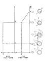
図3は、本発明の第1実施形態に係るレーザ溶接装置100の模式図である。まず、図3を参照して、本実施形態におけるレーザ溶接装置100の構造について説明する。なお、図3に示す破線は、制御装置(制御部)40から出力される制御信号の信号線を示しており、図3に示す一点破線は、溶接用レーザ光L1および加熱用レーザ光L2を示している。
2. About Laser
本実施形態におけるレーザ溶接装置100は、2次電池10の製造において、電池ケース12と封口板13とを溶接する際、および、封口板13と蓋体19とを溶接する際に用いられる。本実施形態では、封口板13と蓋体19との溶接を一例として、以下にレーザ溶接装置100の装置構成を簡単に説明する。
The
レーザ溶接装置100は、溶接用レーザ光L1を、2つのワークである封口板13と蓋体19との境界に形成された閉ループ状の溶接経路C(図2参照)に沿って、溶接経路Cを周回するように照射(走査)することにより、封口板13と蓋体19とを溶接する装置である。
The
レーザ溶接装置100は、溶接用レーザ光L1を溶接経路Cに沿って走査する第1照射部20と、溶接経路Cの全体を加熱するように、溶接経路Cの全体に加熱用レーザ光L2を照射する第2照射部30と、を備えている。さらに、レーザ溶接装置100は、第1照射部20および第2照射部30を制御する制御部40を備えている。
The
第1照射部20は、YAGレーザなどの溶接用レーザ光L1を発するレーザ発振機21と、コリメートレンズ22と、集光レンズ24、26と、反射鏡25と、XYガルバノスキャナユニット(以下、ガルバノスキャナ)27と、を少なくとも備えている。なお、第1照射部20は、制御装置40の制御信号により、Z軸方向に(溶接用レーザ光L1の進行方向に)集光レンズ24を移動させ、溶接用レーザ光L1の照射範囲を調整する駆動ユニット29をさらに備えている。
The
本実施形態では、レーザ発振機21が発するレーザに、YAGレーザを例示したが、溶接を行うことができるのであれば、例えば、ディスクレーザ、ファイバレーザ、CO2レーザなどの固体レーザ、ヘリウムネオンレーザ、アルゴンイオンレーザなどの気体レーザ、または半導体レーザなどであってもよい。また、溶接用レーザ光L1は、パルスレ方式またはCW方式のいずれの方式で出力されてもよい。
In the present embodiment, the laser emitted by the
レーザ発振機21から発せられた溶接用レーザ光L1は、光ファイバ28を介して、処理室R内に入力され、コリメートレンズ22を通過し、集光レンズ24で集光された後、反射鏡25を反射し、集光レンズ26を介して、ガルバノスキャナ27に入光される。ガルバノスキャナ27は、高速かつ正確な位置に溶接用レーザ光L1を走査するための装置である。ガルバノスキャナ27は、一般的な装置であり、モータ(図示せず)に軸支された一対のガルバノミラー(図示せず)を有している。制御装置40は、このモータを駆動制御することにより、ガルバノミラーの反射角を変更し、溶接用レーザ光L1を溶接経路Cに沿って走査することができる。
The welding laser beam L1 emitted from the
ここで、コリメートレンズ22は、ガルバノスキャナ27に入光される溶接用レーザ光L1を予め平行光にするためのレンズである。なお、ガルバノスキャナ27の出力側には、集光レンズ(図示せず)が設けられており、この集光レンズで、ガルバノスキャナ27からの溶接用レーザ光L1を溶接経路C上に集光することができる。
Here, the collimating
第2照射部30は、ファイバレーザなどの加熱用レーザ光L2を発するレーザ発振機31と、コリメートレンズ32と、集光レンズ34、36と、反射鏡35と、XYガルバノスキャナユニット(以下、ガルバノスキャナ)37と、を少なくとも備えている。なお、第2照射部30は、第1照射部20と同様に、制御装置40の制御信号により、Z軸方向に(加熱用レーザ光L2の進行方向に)集光レンズ34を移動させ、加熱用レーザ光L2の照射範囲を調整する駆動ユニット39を備えている。処理室R内の第2照射部30の各部材は、第1照射部20と同様に機能するので、ここでは、その詳細を省略する。
The
これに加えて、第2照射部30は、コリメートレンズ32と集光レンズ34の間に、回折光学素子(DOE:Diffractive Optical Element)33を備えている。回折光学素子33は、回折現象により、加熱用レーザ光L2の照射領域の形状を変換する素子である。具体的には、回折光学素子33は、加熱用レーザ光L2が溶接経路Cの全体に照射されるように、コリメートレンズ32を通過した加熱用レーザ光L2の照射領域の形状をリング状に変換するように構成されている。このように、コリメートレンズ32を通過した加熱用レーザ光L2は、平行光となり、この平行光が、回折光学素子33に入光されるため、加熱用レーザ光L2の照射領域の形状をより精度良くリング状に変換することができ、集光レンズ34、36で、リング状に変換された加熱用レーザ光L2を効率良く集光することができる。なお、本実施形態では、好ましい態様として、加熱用レーザ光L2を、コリメートレンズ32に通過させた後、回折光学素子33に通過させたが、例えば、加熱用レーザ光L2を、回折光学素子33に通過させた後、コリメートレンズ32に通過させてもよい。
In addition to this, the
レーザ発振機31から発せられた加熱用レーザ光L2は、光ファイバ38を介して、処理室R内に入力され、コリメートレンズ32を通過後、回折光学素子33を通過し、回折光学素子33で照射領域の形状が変換された加熱用レーザ光L2が、集光レンズ34で集光される。集光された加熱用レーザ光L2は、反射鏡35を反射し、集光レンズ36を介して、ガルバノスキャナ37に入光される。ガルバノスキャナ37では、第1照射部20と同様に、制御装置40が、一対のガルバノミラー(図示せず)に軸支されたモータ(図示せず)を駆動することにより、加熱用レーザ光L2を溶接経路Cの全体に照射するように、溶接経路Cに加熱用レーザ光L2の照射領域を位置合わせする。
The heating laser beam L2 emitted from the
制御装置40は、第1照射部20のレーザ発振機21による溶接用レーザ光L1の発するタイミングおよびその出力を制御するとともに、上述したように駆動ユニット29およびガルバノスキャナ27を制御する。同様に、制御装置40は、第2照射部30のレーザ発振機31による加熱用レーザ光L2の発するタイミングおよびその出力を制御するとともに、上述したように駆動ユニット39およびガルバノスキャナ37を制御する。制御装置40は、以下に示す溶接を行うように、これらの機器に制御信号を出力し、これらの機器を制御するプログラムを有している。
The
具体的には、本実施形態では、制御装置40は、加熱用レーザ光L2を、溶接経路Cの全体に所定時間照射するように第2照射部30のレーザ発振機31等を制御する。その後、制御装置40は、加熱用レーザ光L2による溶接経路Cの全体の照射を継続するように第2照射部30のレーザ発振機21を制御する。これと同時に、制御装置40は、ガルバノスキャナ27を制御することで溶接経路Cに沿って溶接用レーザ光L1を走査させ、溶接用レーザ光L1が溶接経路Cを周回するように、第1照射部20のレーザ発振機21を制御する。本実施形態では、走査させた溶接用レーザ光L1が溶接経路Cを周回した後、溶接用レーザ光L1および加熱用レーザ光L2の照射を終了するように、制御装置40は、第1照射部20のレーザ発振機21と、第2照射部30のレーザ発振機31を制御する。
Specifically, in the present embodiment, the
3.レーザ溶接方法について
図4は、第1実施形態に係るレーザ溶接装置100による溶接方法を説明するためのタイミングチャートである。以下に、封口板13と蓋体19とのレーザ溶接方法を説明する。まず、図2に示すように、蓋体19が、封口板13に配置されている状態で、2次電池10を、処理室R内に投入する。
3. About Laser Welding Method FIG. 4 is a timing chart for explaining a welding method by the
次に、図4に示すように、制御装置40が、第2照射部30を制御することにより、加熱用レーザ光L2を、溶接経路Cの全体に所定時間(具体的には時刻t1まで)照射する。これにより、溶接経路Cの全体を予備加熱する。具体的には、上述した如く、制御装置40は、加熱用レーザ光L2を発するようにレーザ発振機31を制御し、加熱用レーザ光L2を溶接経路Cの全体に照射するように駆動ユニット39およびガルバノスキャナ27を制御する。
Next, as shown in FIG. 4, the
ここで、加熱用レーザ光L2の出力(レーザ強度)P2は、蓋体19および封口板13の材料が溶融しない出力である。したがって、予備加熱では、これらの材料は融点以下の温度になる。予備加熱する時間(時刻0から時刻t1までの時間)は、加熱用レーザ光L2による入熱量と、入熱された熱の2次電池10から放熱量との、バランスが取れた状態、すなわち、照射時間に拘わらず溶接経路Cの温度が安定する(一定となる)時間まで予備加熱することが好ましい。これにより、溶接経路Cを走査する溶接用レーザ光L1による溶接部分Wの溶け込み深さをより安定させることができる。
Here, the output (laser intensity) P2 of the heating laser beam L2 is an output that the materials of the
次に、予備加熱後(時刻t1後)に、制御装置40により、加熱用レーザ光L2の照射を継続しつつ、溶接経路Cに沿って溶接用レーザ光L1を走査し、溶接用レーザ光L1を溶接経路Cに沿って周回させる。
Next, after preheating (after time t1), the
具体的には、制御装置40により、第2照射部30における予備加熱後の加熱用レーザ光L2の照射状態を維持しつつ、第1照射部20を以下の如く制御する。具体的には、制御装置40は、レーザ発振機21から溶接用レーザ光L1を発するように制御し、溶接経路Cに沿って溶接用レーザ光L1を走査し、溶接用レーザ光L1が溶接経路Cを周回するように、駆動ユニット29およびガルバノスキャナ27を制御する(時刻t1〜時刻t2)。
Specifically, the
本実施形態では、溶接用レーザ光L1が溶接経路Cを周回した後、制御装置40は、溶接用レーザ光L1の照射と、加熱用レーザ光L2の照射を終了するように、レーザ発振機21、31を制御する。
In the present embodiment, after the welding laser light L1 circulates the welding path C, the
本実施形態では、加熱用レーザ光L2で、溶接経路Cの全体を予備加熱し、その後も加熱用レーザ光L2の照射を継続した。これにより、加熱用レーザ光L2を照射しない場合に比べて、低い出力で、溶接用レーザ光L1により蓋体19と封口板13とを溶接することができる。このようにして、走査される溶接用レーザ光L1の入熱より、その後溶接される溶接経路Cの部分の昇温を低減することができる。
In the present embodiment, the entire welding path C is preheated by the heating laser beam L2, and the irradiation of the heating laser beam L2 is continued thereafter. Thus, the
以上のことから、本実施形態では、溶接用レーザ光L1の複雑な出力制御を行うことなく、溶接時に溶接経路Cの溶接始めの部分Sと溶接終わりの部分Eとの温度差を小さくすることができ、溶接経路Cに沿って形成された溶接部分Wの溶け込み深さをより均一にすることができる。なお、本実施形態では、溶接用レーザ光L1の出力P1、および加熱用レーザ光L2の出力P2を一定としたが、たとえば、溶け込み深さが均一になるのであれば、その出力を僅かに制御してもよい。 From the above, in the present embodiment, the temperature difference between the welding start portion S and the welding end portion E of the welding path C is reduced during welding without performing complicated output control of the welding laser beam L1. It is possible to make the penetration depth of the welded portion W formed along the welding path C more uniform. In the present embodiment, although the output P1 of the welding laser beam L1 and the output P2 of the heating laser beam L2 are constant, for example, if the penetration depth becomes uniform, the output is slightly controlled You may
〔第2実施形態〕
図5は、第2実施形態に係るレーザ溶接装置100による溶接方法を説明するためのタイミングチャートである。第2実施形態に係るレーザ溶接装置100が、第1実施形態と相違する点は、制御装置40による第2照射部30の制御である。
Second Embodiment
FIG. 5 is a timing chart for explaining a welding method by the
具体的には、制御装置40は、第1実施形態の制御に加え、溶接用レーザ光L1の照射の終了後、継続して加熱用レーザ光L2が所定時間照射されるように、第2照射部30を制御する。
Specifically, in addition to the control of the first embodiment, the
より具体的には、図5に示すように、本実施形態では、走査された溶接用レーザ光L1が溶接経路Cを周回したタイミング(時刻t2)で、制御装置40は、溶接用レーザ光L1の照射を終了させる。一方、加熱用レーザ光L2は、時刻t3まで、継続して溶接経路Cの全体を加熱する。
More specifically, as shown in FIG. 5, in the present embodiment, at the timing (time t2) at which the scanned welding laser beam L1 circulates the welding path C, the
本実施形態によれば、第1実施形態に示す上述した効果に加えて、さらに、溶接用レーザ光L1により溶接が終了した後も、加熱用レーザ光L2を所定時間照射しているので、溶接部分Wの全体が均一に加熱され、その後冷却される。これにより、溶接部分W全体の凝固速度のばらつきを抑え、溶接部分Wをより均一な組織にすることができる。 According to the present embodiment, in addition to the above-described effects shown in the first embodiment, the heating laser beam L2 is irradiated for a predetermined time even after the welding is completed by the welding laser beam L1. The entire part W is uniformly heated and then cooled. Thereby, the dispersion | variation in the solidification speed of the whole welding part W can be suppressed, and the welding part W can be made into a more uniform structure | tissue.
〔第3実施形態〕
図6は、第3実施形態に係るレーザ溶接装置100による溶接方法を説明するためのタイミングチャートであり、図7は、第3実施形態の変形例に係るレーザ溶接装置100による溶接方法を説明するためのタイミングチャートである。
Third Embodiment
FIG. 6 is a timing chart for explaining the welding method by the
第3実施形態に係るレーザ溶接装置100が、第2実施形態と相違する点は、制御装置40が、溶接用レーザ光L1の照射の終了後、継続して照射される加熱用レーザ光L2の出力を減少させるように、第2照射部30を制御している点である。
The difference between the
具体的には、図6に示すように、本実施形態では、溶接用レーザ光L1が溶接経路Cを周回したタイミング(時刻t2)で、制御装置40は、溶接用レーザ光L1の照射を終了させる。加熱用レーザ光L2は、時刻t3まで、継続して溶接経路Cの全体を加熱する。この際、時刻t3以前に照射する加熱用レーザ光L2の出力に対して、時刻t3以後に照射する加熱用レーザ光L2の出力を一定の出力に減少させる。
Specifically, as shown in FIG. 6, in the present embodiment, the
本実施形態によれば、第2実施形態に示す上述した効果に加えて、さらに、加熱用レーザ光L2の出力を減少させることにより、溶接部分Wの温度を段階的に下げることができる。これにより、溶接部分Wの凝固速度を緩やかにし、溶接部分Wのガス抜けが向上し、溶接部分Wのボイドの生成を抑制することができる。 According to the present embodiment, in addition to the above-described effects shown in the second embodiment, the temperature of the welded portion W can be lowered stepwise by further reducing the output of the heating laser beam L2. As a result, the solidification speed of the welded portion W can be slowed down, the outgassing of the welded portion W can be improved, and the formation of voids in the welded portion W can be suppressed.
図6では、時刻t3以前に照射する加熱用レーザ光L2の出力に対して、時刻t3以後に照射する加熱用レーザ光L2の出力を一定の出力に減少させたが、例えば、図7に示すように、時刻t3以後に照射する加熱用レーザ光L2の出力を単調減少させてもよい。この他にも、時刻t3以後に照射する加熱用レーザ光L2の出力をステップ状に減少させてもよい。 In FIG. 6, the output of the heating laser light L2 emitted after time t3 is reduced to a constant output with respect to the output of the heating laser light L2 emitted before time t3, for example, as shown in FIG. 7. Thus, the output of the heating laser light L2 to be applied after time t3 may be monotonically decreased. Besides this, the output of the heating laser beam L2 to be applied after time t3 may be reduced stepwise.
以上、本発明の実施の形態を用いて詳述してきたが、具体的な構成はこの実施形態及び実施例に限定されるものではなく、本発明の要旨を逸脱しない範囲における設計変更があっても、それらは本発明に含まれるものである。 As mentioned above, although it explained in full detail using the embodiment of the present invention, the concrete composition is not limited to this embodiment and an example, and there is design change in the range which does not deviate from the gist of the present invention. Also, they are included in the present invention.
13:封口板(ワーク)、19:蓋体(ワーク)、20:第1照射部、30:第2照射部、40:制御装置、L1:溶接用レーザ光、L2:加熱用レーザ光 13: sealing plate (work), 19: lid (work), 20: first irradiation unit, 30: second irradiation unit, 40: control device, L1: laser beam for welding, L2: laser beam for heating
Claims (2)
加熱用レーザ光を、前記溶接経路の全体に所定時間照射することにより、前記溶接経路の全体を予備加熱する工程と、
前記予備加熱する工程後に、前記加熱用レーザ光の照射を継続しつつ、前記溶接経路に沿って前記溶接用レーザ光を走査し、前記溶接用レーザ光が前記溶接経路を周回した後、前記溶接用レーザ光の照射を終了するものであり、
前記溶接用レーザ光の照射の終了後、継続して前記加熱用レーザ光を所定時間照射するとともに、継続して照射される前記加熱用レーザ光の出力を減少させることを特徴とするレーザ溶接方法。 A laser welding method for welding two workpieces together by irradiating a welding laser beam so as to go around the welding route along a closed loop welding route formed at the boundary between the two workpieces. ,
Preheating the entire welding path by irradiating the whole of the welding path for a predetermined time with a laser beam for heating;
After the step of preheating, while the irradiation of the heating laser beam is continued, the laser beam for welding is scanned along the welding path, and the laser beam for welding travels around the welding path, and then the welding is performed. It is intended to end the irradiation of the use laser light,
A laser welding method characterized by continuously irradiating the heating laser light for a predetermined time after the irradiation of the welding laser light is finished and reducing an output of the heating laser light which is continuously irradiated. .
前記レーザ溶接装置は、前記溶接用レーザ光を前記溶接経路に沿って照射する第1照射部と、
前記溶接経路の全体を加熱するように、前記溶接経路の全体に加熱用レーザ光を照射する第2照射部と、
前記第1照射部および前記第2照射部を制御する制御部と、を備え、
前記制御部は、前記加熱用レーザ光を、前記溶接経路の全体に所定時間照射するように前記第2照射部を制御した後に、前記加熱用レーザ光の照射を継続するように前記第2照射部を制御しつつ、前記溶接経路に沿って前記溶接用レーザ光を走査させ、前記溶接用レーザ光を前記溶接経路に沿って周回させた後に、前記溶接用レーザ光の照射を終了するように、前記第1照射部を制御するものであり、
前記制御部は、前記溶接用レーザ光の照射の終了後、継続して前記加熱用レーザ光が所定時間照射されるように、前記第2照射部を制御するとともに、継続して照射される前記加熱用レーザ光の出力が減少するように、前記第2照射部を制御することを特徴とするレーザ溶接装置。 A laser welding apparatus for welding two work pieces by irradiating welding laser light so as to go around the welding path along a closed loop welding path formed at the boundary between the two works. ,
The laser welding apparatus includes: a first irradiation unit that irradiates the welding laser light along the welding path;
A second irradiation unit configured to irradiate a heating laser beam to the entire welding path so as to heat the entire welding path;
A control unit that controls the first irradiation unit and the second irradiation unit;
The control unit controls the second irradiation unit to irradiate the heating laser beam to the entire welding path for a predetermined time, and then continues the irradiation of the heating laser beam. The laser beam for welding is scanned along the welding path while controlling the part, and after the laser beam for welding is circulated along the welding path, the irradiation of the laser beam for welding is ended. Controlling the first irradiation unit ,
The control unit controls the second irradiation unit so that the heating laser light is continuously irradiated for a predetermined time after the irradiation of the welding laser light is finished, and the irradiation is continuously performed. A laser welding apparatus characterized in that the second irradiation unit is controlled so that the output of the heating laser light is reduced .
Priority Applications (4)
| Application Number | Priority Date | Filing Date | Title |
|---|---|---|---|
| JP2016250029A JP6524992B2 (en) | 2016-12-22 | 2016-12-22 | Laser welding method and laser welding apparatus |
| CN201711363455.XA CN108232047B (en) | 2016-12-22 | 2017-12-18 | Laser welding method and laser welding device |
| US15/845,034 US10821544B2 (en) | 2016-12-22 | 2017-12-18 | Laser welding method and laser welding device |
| KR1020170175050A KR102057063B1 (en) | 2016-12-22 | 2017-12-19 | Laser welding method and laser welding device |
Applications Claiming Priority (1)
| Application Number | Priority Date | Filing Date | Title |
|---|---|---|---|
| JP2016250029A JP6524992B2 (en) | 2016-12-22 | 2016-12-22 | Laser welding method and laser welding apparatus |
Publications (2)
| Publication Number | Publication Date |
|---|---|
| JP2018103202A JP2018103202A (en) | 2018-07-05 |
| JP6524992B2 true JP6524992B2 (en) | 2019-06-05 |
Family
ID=62624890
Family Applications (1)
| Application Number | Title | Priority Date | Filing Date |
|---|---|---|---|
| JP2016250029A Active JP6524992B2 (en) | 2016-12-22 | 2016-12-22 | Laser welding method and laser welding apparatus |
Country Status (4)
| Country | Link |
|---|---|
| US (1) | US10821544B2 (en) |
| JP (1) | JP6524992B2 (en) |
| KR (1) | KR102057063B1 (en) |
| CN (1) | CN108232047B (en) |
Families Citing this family (1)
| Publication number | Priority date | Publication date | Assignee | Title |
|---|---|---|---|---|
| JP7505332B2 (en) * | 2020-08-28 | 2024-06-25 | 中国電力株式会社 | Apparatus and method for determining flooding of air switch |
Family Cites Families (18)
| Publication number | Priority date | Publication date | Assignee | Title |
|---|---|---|---|---|
| US4501950A (en) * | 1982-09-07 | 1985-02-26 | Caterpillar Tractor Co. | Adaptive welding system |
| JPS5976689A (en) * | 1982-10-22 | 1984-05-01 | Fujitsu Ltd | Airtight sealing method of aluminum package |
| JP2002321074A (en) * | 2001-04-27 | 2002-11-05 | Honda Motor Co Ltd | Method of laser welding |
| JP2004337881A (en) | 2003-05-13 | 2004-12-02 | Matsushita Electric Ind Co Ltd | Laser beam machining method and laser beam machining apparatus |
| WO2006116722A2 (en) * | 2005-04-28 | 2006-11-02 | The Pennsylvania State Research Foundation | Apparatus and method for conducting laser stir welding |
| JP5070861B2 (en) * | 2006-03-23 | 2012-11-14 | 日産自動車株式会社 | Laser welding apparatus and method |
| KR101587941B1 (en) * | 2007-11-19 | 2016-01-22 | 가부시키가이샤 아마다미야치 | Laser light application device |
| JP2009245758A (en) | 2008-03-31 | 2009-10-22 | Sanyo Electric Co Ltd | Method for manufacturing sealed battery |
| TWI451928B (en) * | 2010-10-12 | 2014-09-11 | Nippon Steel & Sumitomo Metal Corp | Laser welding method |
| US9378297B2 (en) * | 2011-03-07 | 2016-06-28 | Microsoft Technology Licensing, Llc | Task-based address bar and tabs scaling |
| US8766140B2 (en) * | 2011-10-06 | 2014-07-01 | Lincoln Global, Inc. | Apparatus and method for laser cleaning of coated materials prior to welding |
| CN103182604B (en) | 2013-03-12 | 2016-04-06 | 镭射谷科技(深圳)有限公司 | Laser compound welding method and system |
| EP2972479B1 (en) * | 2013-03-13 | 2020-09-09 | IPG Photonics (Canada) Inc. | Methods and systems for characterizing laser machining properties by measuring keyhole dynamics using interferometry |
| JP5842851B2 (en) * | 2013-03-29 | 2016-01-13 | トヨタ自動車株式会社 | Welded part inspection device and inspection method |
| JP5947740B2 (en) * | 2013-03-29 | 2016-07-06 | トヨタ自動車株式会社 | Welded part inspection device and inspection method |
| JP5849985B2 (en) * | 2013-04-15 | 2016-02-03 | トヨタ自動車株式会社 | Welded part inspection device and inspection method |
| KR101509715B1 (en) * | 2013-10-15 | 2015-04-07 | 현대자동차 주식회사 | Laser welding device |
| JP6108178B2 (en) | 2014-06-16 | 2017-04-05 | トヨタ自動車株式会社 | Laser welding apparatus and laser welding method |
-
2016
- 2016-12-22 JP JP2016250029A patent/JP6524992B2/en active Active
-
2017
- 2017-12-18 US US15/845,034 patent/US10821544B2/en active Active
- 2017-12-18 CN CN201711363455.XA patent/CN108232047B/en active Active
- 2017-12-19 KR KR1020170175050A patent/KR102057063B1/en active IP Right Grant
Also Published As
| Publication number | Publication date |
|---|---|
| JP2018103202A (en) | 2018-07-05 |
| US10821544B2 (en) | 2020-11-03 |
| CN108232047A (en) | 2018-06-29 |
| US20180178321A1 (en) | 2018-06-28 |
| CN108232047B (en) | 2020-12-18 |
| KR102057063B1 (en) | 2019-12-18 |
| KR20180073475A (en) | 2018-07-02 |
Similar Documents
| Publication | Publication Date | Title |
|---|---|---|
| JP6108178B2 (en) | Laser welding apparatus and laser welding method | |
| JP6799755B2 (en) | Laser welding method | |
| WO2013186862A1 (en) | Welding device, welding method, and method for producing cell | |
| JP2009262183A (en) | Head and method for laser arc hybrid welding | |
| JP2008041868A (en) | Impurity activating method and laser irradiation apparatus | |
| JP7382554B2 (en) | Laser processing equipment and laser processing method using the same | |
| JP7398650B2 (en) | Laser processing equipment and output control device for laser processing equipment | |
| JP6777023B2 (en) | Welding method of laminated metal foil | |
| JP6458630B2 (en) | Welding method and welding apparatus | |
| JP6524992B2 (en) | Laser welding method and laser welding apparatus | |
| JP6468175B2 (en) | Manufacturing method of sealed container | |
| JP2003340582A (en) | Apparatus and method for laser welding | |
| WO2019064325A1 (en) | Laser processing method and laser processing device | |
| JP7060335B2 (en) | Welding equipment and welding method | |
| JP2020199513A (en) | Laser processing machine and control method of laser processing machine | |
| JP6832198B2 (en) | Laser welding equipment, laser welding method and laser processing lens | |
| JP6387927B2 (en) | Laser welding method | |
| JP2016107293A (en) | Welding device | |
| JP7465241B2 (en) | Laser welding device control device | |
| JP7105912B2 (en) | LASER WELDING METHOD AND LAMINATED BODY | |
| JP2501594B2 (en) | Focus position adjustment method of laser processing machine | |
| JP5013720B2 (en) | Laser processing method | |
| KR20240007572A (en) | Welding device, welding method, battery manufacturing device and vehicle manufacturing device | |
| JP2021122831A (en) | Laser joining method and junction structure | |
| KR20240053919A (en) | Laser welding device |
Legal Events
| Date | Code | Title | Description |
|---|---|---|---|
| A977 | Report on retrieval |
Free format text: JAPANESE INTERMEDIATE CODE: A971007 Effective date: 20181019 |
|
| A131 | Notification of reasons for refusal |
Free format text: JAPANESE INTERMEDIATE CODE: A131 Effective date: 20181030 |
|
| A521 | Request for written amendment filed |
Free format text: JAPANESE INTERMEDIATE CODE: A523 Effective date: 20181220 |
|
| TRDD | Decision of grant or rejection written | ||
| A01 | Written decision to grant a patent or to grant a registration (utility model) |
Free format text: JAPANESE INTERMEDIATE CODE: A01 Effective date: 20190409 |
|
| A61 | First payment of annual fees (during grant procedure) |
Free format text: JAPANESE INTERMEDIATE CODE: A61 Effective date: 20190422 |
|
| R151 | Written notification of patent or utility model registration |
Ref document number: 6524992 Country of ref document: JP Free format text: JAPANESE INTERMEDIATE CODE: R151 |