JP6520739B2 - Drive unit - Google Patents
Drive unit Download PDFInfo
- Publication number
- JP6520739B2 JP6520739B2 JP2016016925A JP2016016925A JP6520739B2 JP 6520739 B2 JP6520739 B2 JP 6520739B2 JP 2016016925 A JP2016016925 A JP 2016016925A JP 2016016925 A JP2016016925 A JP 2016016925A JP 6520739 B2 JP6520739 B2 JP 6520739B2
- Authority
- JP
- Japan
- Prior art keywords
- cover
- terminal
- lead wire
- hole
- housing
- Prior art date
- Legal status (The legal status is an assumption and is not a legal conclusion. Google has not performed a legal analysis and makes no representation as to the accuracy of the status listed.)
- Active
Links
- WABPQHHGFIMREM-UHFFFAOYSA-N lead(0) Chemical compound [Pb] WABPQHHGFIMREM-UHFFFAOYSA-N 0.000 claims description 77
- 230000000149 penetrating effect Effects 0.000 claims description 9
- 229910052751 metal Inorganic materials 0.000 claims description 4
- 239000002184 metal Substances 0.000 claims description 4
- 238000003780 insertion Methods 0.000 description 15
- 230000037431 insertion Effects 0.000 description 15
- 239000000758 substrate Substances 0.000 description 13
- 238000005476 soldering Methods 0.000 description 10
- 238000004804 winding Methods 0.000 description 7
- 238000001514 detection method Methods 0.000 description 3
- 238000000034 method Methods 0.000 description 3
- 239000011347 resin Substances 0.000 description 3
- 229920005989 resin Polymers 0.000 description 3
- 229910000679 solder Inorganic materials 0.000 description 3
- 239000003990 capacitor Substances 0.000 description 2
- 239000000428 dust Substances 0.000 description 2
- 229910052782 aluminium Inorganic materials 0.000 description 1
- XAGFODPZIPBFFR-UHFFFAOYSA-N aluminium Chemical compound [Al] XAGFODPZIPBFFR-UHFFFAOYSA-N 0.000 description 1
- 230000000694 effects Effects 0.000 description 1
- 239000013013 elastic material Substances 0.000 description 1
- 230000017525 heat dissipation Effects 0.000 description 1
- XLYOFNOQVPJJNP-UHFFFAOYSA-N water Substances O XLYOFNOQVPJJNP-UHFFFAOYSA-N 0.000 description 1
- 238000003466 welding Methods 0.000 description 1
Images


Classifications
-
- H—ELECTRICITY
- H02—GENERATION; CONVERSION OR DISTRIBUTION OF ELECTRIC POWER
- H02K—DYNAMO-ELECTRIC MACHINES
- H02K5/00—Casings; Enclosures; Supports
- H02K5/04—Casings or enclosures characterised by the shape, form or construction thereof
- H02K5/10—Casings or enclosures characterised by the shape, form or construction thereof with arrangements for protection from ingress, e.g. water or fingers
-
- B—PERFORMING OPERATIONS; TRANSPORTING
- B62—LAND VEHICLES FOR TRAVELLING OTHERWISE THAN ON RAILS
- B62D—MOTOR VEHICLES; TRAILERS
- B62D5/00—Power-assisted or power-driven steering
- B62D5/04—Power-assisted or power-driven steering electrical, e.g. using an electric servo-motor connected to, or forming part of, the steering gear
- B62D5/0403—Power-assisted or power-driven steering electrical, e.g. using an electric servo-motor connected to, or forming part of, the steering gear characterised by constructional features, e.g. common housing for motor and gear box
- B62D5/0406—Power-assisted or power-driven steering electrical, e.g. using an electric servo-motor connected to, or forming part of, the steering gear characterised by constructional features, e.g. common housing for motor and gear box including housing for electronic control unit
-
- H—ELECTRICITY
- H02—GENERATION; CONVERSION OR DISTRIBUTION OF ELECTRIC POWER
- H02K—DYNAMO-ELECTRIC MACHINES
- H02K11/00—Structural association of dynamo-electric machines with electric components or with devices for shielding, monitoring or protection
- H02K11/30—Structural association with control circuits or drive circuits
- H02K11/33—Drive circuits, e.g. power electronics
-
- H—ELECTRICITY
- H02—GENERATION; CONVERSION OR DISTRIBUTION OF ELECTRIC POWER
- H02K—DYNAMO-ELECTRIC MACHINES
- H02K5/00—Casings; Enclosures; Supports
- H02K5/04—Casings or enclosures characterised by the shape, form or construction thereof
- H02K5/22—Auxiliary parts of casings not covered by groups H02K5/06-H02K5/20, e.g. shaped to form connection boxes or terminal boxes
- H02K5/225—Terminal boxes or connection arrangements
-
- H—ELECTRICITY
- H02—GENERATION; CONVERSION OR DISTRIBUTION OF ELECTRIC POWER
- H02K—DYNAMO-ELECTRIC MACHINES
- H02K7/00—Arrangements for handling mechanical energy structurally associated with dynamo-electric machines, e.g. structural association with mechanical driving motors or auxiliary dynamo-electric machines
- H02K7/08—Structural association with bearings
- H02K7/083—Structural association with bearings radially supporting the rotary shaft at both ends of the rotor
-
- B—PERFORMING OPERATIONS; TRANSPORTING
- B62—LAND VEHICLES FOR TRAVELLING OTHERWISE THAN ON RAILS
- B62D—MOTOR VEHICLES; TRAILERS
- B62D5/00—Power-assisted or power-driven steering
- B62D5/04—Power-assisted or power-driven steering electrical, e.g. using an electric servo-motor connected to, or forming part of, the steering gear
-
- H—ELECTRICITY
- H02—GENERATION; CONVERSION OR DISTRIBUTION OF ELECTRIC POWER
- H02K—DYNAMO-ELECTRIC MACHINES
- H02K11/00—Structural association of dynamo-electric machines with electric components or with devices for shielding, monitoring or protection
- H02K11/20—Structural association of dynamo-electric machines with electric components or with devices for shielding, monitoring or protection for measuring, monitoring, testing, protecting or switching
- H02K11/21—Devices for sensing speed or position, or actuated thereby
-
- H—ELECTRICITY
- H02—GENERATION; CONVERSION OR DISTRIBUTION OF ELECTRIC POWER
- H02K—DYNAMO-ELECTRIC MACHINES
- H02K2211/00—Specific aspects not provided for in the other groups of this subclass relating to measuring or protective devices or electric components
- H02K2211/03—Machines characterised by circuit boards, e.g. pcb
-
- H—ELECTRICITY
- H02—GENERATION; CONVERSION OR DISTRIBUTION OF ELECTRIC POWER
- H02K—DYNAMO-ELECTRIC MACHINES
- H02K3/00—Details of windings
- H02K3/46—Fastening of windings on the stator or rotor structure
- H02K3/50—Fastening of winding heads, equalising connectors, or connections thereto
Landscapes
- Engineering & Computer Science (AREA)
- Power Engineering (AREA)
- Microelectronics & Electronic Packaging (AREA)
- Chemical & Material Sciences (AREA)
- Combustion & Propulsion (AREA)
- Transportation (AREA)
- Mechanical Engineering (AREA)
- Motor Or Generator Frames (AREA)
- Windings For Motors And Generators (AREA)
Description
本発明は、モータおよび制御部を備える駆動装置に関する。 The present invention relates to a drive device including a motor and a control unit.
従来、モータおよびこれを制御する制御部が一体に設けられた駆動装置が知られている。この種の駆動装置において、モータのハウジングには、モータのコイルと制御部とをつなぐリード線を通す孔(以下、リード線挿通孔)が設けられる。リード線挿通孔がハウジング内外を連通させる場合、リード線と制御部とを例えばはんだ付け等により電気的に接続するときに生じる異物がリード線挿通孔を通じてハウジング内に入り込むことが懸念される。これに対して、特許文献1に開示された駆動装置は、リード線挿通孔を塞ぐシール部材を備える。シール部材は、ハウジングを構成する有底筒状のケースの底部とフレームエンドとの間に挟まれて保持されている。 2. Description of the Related Art Conventionally, there is known a drive device integrally provided with a motor and a control unit that controls the motor. In this type of drive device, the motor housing is provided with a hole (hereinafter referred to as a lead wire insertion hole) for passing a lead wire connecting the motor coil and the control unit. When the lead wire insertion hole allows the inside and the outside of the housing to communicate with each other, there is a concern that foreign matter generated when the lead wire and the control unit are electrically connected, for example, by soldering may enter the housing through the lead wire insertion hole. On the other hand, the drive device disclosed in Patent Document 1 includes a seal member that closes the lead wire insertion hole. The seal member is held between the bottom of the bottomed cylindrical case constituting the housing and the frame end.
ところが、上記シール部材は、リード線と制御部との接続時におけるハウジング内への異物侵入防止のために必要なだけであって、駆動装置の使用時には不要なものである。そのため、組み付け性の向上および部品点数削減のためにシール部材を削減することが求められている。
本発明は、上述の点に鑑みてなされたものであり、その目的は、ハウジングのリード線挿通孔にシール部材を設けることなく、リード線と制御部との接続時におけるハウジング内への異物侵入を抑制することができる駆動装置を提供することである。
However, the seal member is only necessary to prevent foreign matter from entering the housing when the lead wire and the control unit are connected, and is unnecessary when the drive device is used. Therefore, it is required to reduce the number of seal members in order to improve the assemblability and to reduce the number of parts.
The present invention has been made in view of the above-described point, and an object thereof is the entry of foreign matter into the housing at the time of connection between the lead wire and the control unit without providing a seal member in the lead wire insertion hole of the housing. Providing a driving device capable of suppressing
本発明の駆動装置は、ハウジングと、ハウジング内で固定されているステータと、ステータに対して回転可能に設けられているロータと、ハウジングの外壁に取り付けられているカバーと、カバー内に設けられており、ステータのコイルの通電を制御する制御部と、制御部から延び出しているターミナルと、コイルから延び出しているリード線とを備える。ターミナルは、カバーを貫通している。リード線は、ハウジングを貫通するとともにカバーを貫通しており、カバー外でターミナルに電気的に接続されている。
本発明の第一の態様では、コイルは、第1コイルと第2コイルとを含む。ターミナルは、第1コイルに対応する第1ターミナルと、第2コイルに対応する第2ターミナルとを含む。リード線は、第1ターミナルに電気的に接続されている第1リード線と、第2ターミナルに電気的に接続されている第2リード線とを含む。カバーは、第1ターミナルおよび第1リード線が挿通する第1通孔と、第1通孔とは離間した位置に第2ターミナルおよび第2リード線が挿通する第2通孔とを有する。
本発明の第二の態様では、カバーは、当該カバーの内側へ凹む凹部を有している。リード線のカバー外の一端およびターミナルのカバー外の一端は、凹部の凹み内に収まっている。駆動装置は遮蔽部材をさらに備える。遮蔽部材は、リード線およびターミナルと外部空間とを遮るように凹部の凹みに設けられている。
The drive device of the present invention is provided in a housing, a stator fixed in the housing, a rotor rotatably provided relative to the stator, a cover attached to the outer wall of the housing, and a cover And a control unit for controlling energization of a coil of the stator, a terminal extending from the control unit, and a lead wire extending from the coil. The terminal penetrates the cover. The lead passes through the housing and through the cover, and is electrically connected to the terminal outside the cover.
In a first aspect of the invention, the coil comprises a first coil and a second coil. The terminal includes a first terminal corresponding to the first coil and a second terminal corresponding to the second coil. The lead includes a first lead electrically connected to the first terminal and a second lead electrically connected to the second terminal. The cover has a first through hole through which the first terminal and the first lead are inserted, and a second through hole through which the second terminal and the second lead are inserted at positions separated from the first through hole.
In the second aspect of the present invention, the cover has a recess that is recessed to the inside of the cover. One end of the lead wire cover and the other end of the terminal cover fit within the recess of the recess. The drive further comprises a shielding member. The shielding member is provided in the recess of the recess so as to block the lead wire and the terminal and the external space.
このように構成された駆動装置は、カバーをハウジングに取り付けた後にリード線とターミナルとを例えばはんだ等で接続することが可能である。この際、リード線とターミナルとの接続時には、ハウジングのリード線挿通孔はカバーで遮られることになる。したがって、ハウジングのリード線挿通孔にシール部材を設けることなく、はんだ付けを行うときに生じるはんだ屑や溶接するときに生じるスパッタ等の異物がリード線挿通孔を通じてハウジング内に侵入することを抑制することができる。シール部材を設ける必要がないことから、組み付け性の向上および部品点数削減が可能となる。 The drive device thus configured can connect the lead wire and the terminal by, for example, soldering after the cover is attached to the housing. At this time, at the time of connection between the lead wire and the terminal, the lead wire insertion hole of the housing is interrupted by the cover. Therefore, without providing a seal member in the lead wire insertion hole of the housing, it is possible to suppress foreign matter such as solder chips generated during soldering or spatter generated during welding from entering the housing through the lead wire insertion hole. be able to. Since it is not necessary to provide a seal member, the assemblability can be improved and the number of parts can be reduced.
以下、本発明の複数の実施形態を図面に基づき説明する。複数の実施形態において実質的に同一の構成には同一の符号を付して説明を省略する。
[第1実施形態]
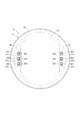
本発明の第1実施形態による駆動装置を図1に示す。駆動装置10は、車両の運転者の操舵を補助する電動パワーステアリング装置の駆動源として用いられる。
Hereinafter, a plurality of embodiments of the present invention will be described based on the drawings. The same reference numerals are given to substantially the same configuration in the plurality of embodiments and the description will be omitted.
First Embodiment
A drive according to a first embodiment of the invention is shown in FIG. The
先ず、駆動装置10の全体的な構成について図1、図2を参照して説明する。
駆動装置10は、モータ11およびこれを制御する制御部12が一体に設けられている機電一体型の駆動装置である。
First, the overall configuration of the
The
モータ11は、3相ブラシレスモータであって、ステータ21、ロータ22、およびそれらを収容するハウジング23を備えている。
ステータ21は、ハウジング23内で固定されているステータコア24と、ステータコア24に組み付けられている2組の三相コイル(以下、コイル)25とを有している。コイル25を構成する各相巻線からは、それぞれ1本ずつリード線261、262、263が延び出している。以降、リード線261、262、263を区別しない場合、単に「リード線26」と記載する。
The
The
ロータ22は、軸受29、31により支持されている回転軸32と、回転軸32に嵌めつけられているロータコア33とを有している。ロータ22は、ステータ21の内側で当該ステータ21に対して回転可能である。回転軸32の一端には、永久磁石からなる被検出部材34が設けられている。この被検出部材34は、後述の回転角センサ42がロータ22の回転角を検出するために用いられる。
The
ハウジング23は、筒状のケース35と、ケース35の一端に設けられている第1フレームエンド36と、ケース35の他端に設けられている第2フレームエンド37とを有している。第1フレームエンド36および第2フレームエンド37は、ケース35を挟持しており、図示しない複数のボルトにより互いに締結されている。軸受29は第1フレームエンド36の中央部に設けられており、軸受31は第2フレームエンド37の中央部に設けられている。第1フレームエンド36は、リード線26が挿通しているリード線挿通孔38を有している。本実施形態では、リード線挿通孔38は、リード線26毎に設けられている。
The
ハウジング23の外壁であって、第1フレームエン36の制御部12側の壁部には、カバー39が取り付けられている。本実施形態では、カバー39はカップ状である。カバー39は、外部の衝撃から制御部12を保護したり、制御部12への埃や水等の浸入を防止したりする。
A
制御部12は、各種の電子部品41〜46と、それらが実装された基板47とを備えている。
基板47は、例えばプリント基板であり、第1フレームエンド36と対向するように設けられている。基板47の2つの主面のうち、第1フレームエンド36に対向している面を第1主面48とし、その反対側の面を第2主面49とする。
The
The
基板47の第1主面48には、二系統のコイル25にそれぞれ対応するインバータを構成している複数のスイッチング素子41、ロータ22の位置を検出する回転角センサ42、および、スイッチング素子41に対して駆動信号を出力する集積回路43等が実装されている。回転角センサ42は、被検出部材34と対向している。スイッチング素子41および集積回路43は、図示しない放熱ゲルを介して第1フレームエンド36に放熱可能な状態で当接している。第1フレームエンド36はヒートシンクとしても機能する。
On the first
基板47の第2主面49には、ロータ22の位置等に基づいてコイル13の各相巻線に供給する電力についての指令値を演算するマイコン44、電荷を蓄えることでインバータへの電力供給を補助するコンデンサ45、および、コンデンサ45と共にフィルタ回路を構成しているチョークコイル46等が実装されている。
On the second
基板47からは、各リード線261、262、263に対応して1本ずつターミナル511、512、513が延び出している。以降、ターミナル511、512、513を区別しない場合、単に「ターミナル51」と記載する。ターミナル51は、はんだ付けによりリード線26と基板47とに電気的に接続されている。リード線26およびターミナル51の詳細な構成については後述する。
From the
このように構成された駆動装置10は、回転角センサ42の検出信号に基づきコイル25の各相巻線への通電を順次切り替えて回転磁界を発生させて、ロータ22を回転させる。駆動装置10の制御部12はモータ11に対して軸方向の一方側に搭載されている。そのため、制御部12がモータ11の振動を直接受けることを回避することができる。また、制御部12が固定されている第1フレームエンド36は、例えばアルミダイカスト製であり、精密に形成されている。そのため、制御部12とモータ11との位置精度が格段に向上するとともに、制御部12の発する熱を効果的に放出可能である。
The
次に、駆動装置10の特徴的な構成について図1〜図3を参照して説明する。
コイル25の各相巻線と基板47とは、リード線26およびターミナル51を介して互いにつながっている。具体的には、コイル25の第1相巻線は、リード線261およびターミナル511を介して基板47に接続されている。コイル25の第2相巻線は、リード線262およびターミナル512を介して基板47に接続されている。コイル25の第3相巻線は、リード線263およびターミナル513を介して基板47に接続されている。
Next, the characteristic configuration of the
The respective phase windings of the
リード線26は、第1フレームエンド36を貫通するとともにカバー39を貫通している。ターミナル51は、カバー39を貫通している。カバー39は、リード線261およびターミナル511が挿通している通孔521、リード線262およびターミナル512が挿通している通孔522、および、リード線263およびターミナル513が挿通している通孔523を有している。以降、通孔521、522、523を区別しない場合、単に「通孔52」と記載する。通孔52の内壁面のうち制御部12側は、制御部12側ほど内径が大きいテーパ面53である。
The lead 26 penetrates the
リード線26の一端54およびターミナル51の一端55は、カバー39外に突き出しており、カバー39外ではんだ付けにより互いに電気的に接続されている。
駆動装置10は、リード線26およびターミナル51と外部空間とを遮るようにカバー39の外壁に設けられている遮蔽部材56をさらに備える。図2では、便宜上、遮蔽部材56を二点鎖線で示している。遮蔽部材56は、カップ状であり、リード線26の一端54およびターミナル51の一端55に被せられつつ、開口端部がカバー39に例えば接着等で固定されている。
One
The driving
このように構成された駆動装置10は、次の(1)〜(6)の手順で組み付けられる。
(1)ステータ21およびロータ22がハウジング23に組み付けられる。このとき、リード線26は第1フレームエンド36からハウジング23外へ突き出すように設けられる。
(2)電子部品41〜46およびターミナル51が基板47に実装される。
(3)基板47が第1フレームエンド36に固定される。
(4)カバー39が第1フレームエンド36に取り付けられる。このとき、リード線26およびターミナル51がカバー39の通孔52に挿入されつつ、カバー39の開口端部が第1フレームエンド36に組み合わせられて固定される。テーパ面53は、リード線26およびターミナル51を通孔52に案内するガイド部として機能する。
(5)リード線26の一端54とターミナル51の一端55とがカバー39外ではんだ付けにより互いに電気的に接続される。このとき、リード線26と通孔52との隙間が図示しない蓋状の治具により塞がれた状態で、はんだ付けが行われる。
(6)遮蔽部材56がカバー39に固定される。
The
(1) The
(2) The
(3) The
(4) The
(5) One
(6) The shielding
(効果)
以上説明したように、第1実施形態では、駆動装置10は、ハウジング23と、ハウジング23内で固定されているステータ21と、ステータ21に対して回転可能に設けられているロータ22と、ハウジング23の外壁に取り付けられているカバー39と、カバー39内に設けられており、ステータ21のコイル25の通電を制御する制御部12と、制御部12から延び出しており、カバー39を貫通しているターミナル51と、コイル25から延び出しており、ハウジング23を貫通するとともにカバー39を貫通しており、カバー39外でターミナル51に電気的に接続されているリード線26と、を備える。
(effect)
As described above, in the first embodiment, the
このように構成された駆動装置10は、カバー39をハウジング23に取り付けた後にリード線26とターミナル51とを例えばはんだ等で接続することが可能である。この際、リード線26とターミナル51との接続時には、ハウジング23のリード線挿通孔38はカバー39で遮られることになる。したがって、ハウジング23のリード線挿通孔38にシール部材を設けることなく、はんだ付けを行うときに生じるはんだ屑がリード線挿通孔38を通じてハウジング23内に侵入することを抑制することができる。シール部材を設ける必要がないことから、組み付け性を向上させること、および部品点数を削減することができる。リード線挿通孔38にシール部材を設ける必要がないことから、組み付け性の向上および部品点数削減が可能となる。
The
[第2実施形態]
本発明の第2実施形態では、図4に示すように、遮蔽部材61は、リード線26の一端54およびターミナル51の一端55に融着させられた樹脂からなる。つまり、遮蔽部材61は、溶融状態で一端54、55に付着したのち固化した樹脂である。
Second Embodiment
In the second embodiment of the present invention, as shown in FIG. 4, the shielding
[第3実施形態]
本発明の第3実施形態では、図5に示すように、カバー65は、当該カバー65の内側へ凹む凹部66を有している。通孔52は、凹部66の底部に形成されている。リード線26のカバー65外の一端54およびターミナル51のカバー65外の一端55は、凹部66の凹み67内に収まっている。つまり、一端54、55は、凹部66の凹み67から外側に突出していない。凹部66には、遮蔽部材68が嵌め付けられている。
このように一端54、55がカバー65の凹部66の凹み67内に収まっているため、カバー65に突起物を設けることなく、カバー65外でリード線26とターミナル51とを接続することができる。
Third Embodiment
In the third embodiment of the present invention, as shown in FIG. 5, the
Thus, since the one
[第4実施形態]
本発明の第4実施形態では、図6に示すように、遮蔽部材71は、凹部66の凹み67に設けられ、リード線26の一端54およびターミナル51の一端55に融着させられた樹脂からなる。
Fourth Embodiment
In the fourth embodiment of the present invention, as shown in FIG. 6, the shielding
[第5実施形態]
本発明の第5実施形態では、図7に示すように、カバー75の通孔76は、リード線26の一端54とターミナル51の一端55とを組み合わせたものとほぼ同じ大きさに形成されている。そのため、リード線26とターミナル51とをはんだ付けするとき、治具を用いて通孔76を塞ぐ必要がない。
Fifth Embodiment
In the fifth embodiment of the present invention, as shown in FIG. 7, the through
[第6実施形態]
本発明の第6実施形態では、図8に示すように、カバー81は、リード線26およびターミナル51が挿通している通孔52を有するカバー本体部82と、通孔52の内壁面に一体に結合しており、通孔52の隙間を塞ぐようにリード線26およびターミナル51に接触している弾性部83とを有している。カバー本体部82は金属からなる。弾性部83は例えばゴム等の比較的大きな弾性をもつ材料からなる。
このように通孔52とリード線26およびターミナル51との隙間を塞ぐ弾性部83が設けられているため、リード線26とターミナル51とをはんだ付けするとき、治具を用いて通孔52を塞ぐ必要がない。また、カバー本体部82を金属から構成して、カバー81の強度を上げるとともに放熱性を高めることができる。
Sixth Embodiment
In the sixth embodiment of the present invention, as shown in FIG. 8, the
Since
[他の実施形態]
本発明の他の実施形態では、ハウジングのリード線挿通孔は、複数のリード線に対して1つ設けられてもよい。
本発明の他の実施形態では、カバーの通孔は、複数のリード線に対して1つ設けられてもよい。
本発明の他の実施形態では、カバーの通孔の横断面形状は、矩形に限らず、例えば円形等であってもよい。
本発明の他の実施形態では、カバーの通孔の内壁面はテーパ面を有していなくてもよい。または、カバーの通孔の内壁面の全体がテーパ面であってもよい。
[Other embodiments]
In another embodiment of the present invention, one lead wire insertion hole of the housing may be provided for a plurality of lead wires.
In another embodiment of the present invention, one through hole of the cover may be provided for a plurality of lead wires.
In another embodiment of the present invention, the cross-sectional shape of the through hole of the cover is not limited to a rectangle, and may be, for example, a circle or the like.
In another embodiment of the present invention, the inner wall surface of the through hole of the cover may not have a tapered surface. Alternatively, the entire inner wall surface of the through hole of the cover may be a tapered surface.
本発明の他の実施形態では、リード線とターミナルとが周方向に重なっていてもよいし、他の方向に重なっていてもよい。
本発明の他の実施形態では、遮蔽部材の固定方法は、接着に限らず、例えばねじ締結または嵌め込み等の他の方法を用いてもよい。
本発明の他の実施形態では、モータの三相コイルは、1組であってもよいし、3組以上であってもよい。
本発明の他の実施形態では、駆動装置は、電動パワーステアリング装置以外に適用してもよい。
本発明は、上述した実施形態に限定されるものではなく、発明の趣旨を逸脱しない範囲で種々の形態で実施可能である。
In another embodiment of the present invention, the lead wire and the terminal may overlap in the circumferential direction, or may overlap in another direction.
In another embodiment of the present invention, the method of fixing the shielding member is not limited to adhesion, and other methods such as screw fastening or fitting may be used.
In another embodiment of the present invention, the three-phase coils of the motor may be one set or three or more sets.
In another embodiment of the present invention, the drive device may be applied other than the electric power steering device.
The present invention is not limited to the embodiments described above, and can be implemented in various forms without departing from the scope of the invention.
10・・・駆動装置
12・・・制御部
21・・・ステータ
22・・・ロータ
23・・・ハウジング
25・・・コイル
261、262、263・・・リード線
39、65、75、81・・・カバー
511、512、513・・・ターミナル
DESCRIPTION OF
Claims (15)
前記ハウジング内で固定されているステータ(21)と、
前記ステータに対して回転可能に設けられているロータ(22)と、
前記ハウジング外で当該ハウジングの外壁に取り付けられているカバー(39、65、75、81)と、
前記カバー内に設けられており、前記ステータのコイル(25)の通電を制御する制御部(12)と、
前記制御部から延び出しており、前記カバーを貫通しているターミナル(511、512、513)と、
前記コイルから延び出しており、前記ハウジングを貫通するとともに前記カバーを貫通しており、前記カバー外で前記ターミナルに電気的に接続されているリード線(261、262、263)と、
を備え、
前記コイルは、第1コイルと第2コイルとを含み、
前記ターミナルは、前記第1コイルに対応する第1ターミナルと、前記第2コイルに対応する第2ターミナルとを含み、
前記リード線は、前記第1ターミナルに電気的に接続されている第1リード線と、前記第2ターミナルに電気的に接続されている第2リード線とを含み、
前記カバーは、前記第1ターミナルおよび前記第1リード線が挿通する第1通孔(521、522、523、76)と、前記第1通孔とは離間した位置に前記第2ターミナルおよび前記第2リード線が挿通する第2通孔(521、522、523、76)とを有する駆動装置。 A housing (23),
A stator (21) fixed in said housing;
A rotor (22) rotatably provided relative to the stator;
A cover (39, 65, 75, 81) attached to the outer wall of the housing outside the housing;
A control unit (12) provided in the cover and controlling energization of the coil (25) of the stator;
Terminals (511, 512, 513) extending from the control unit and penetrating the cover;
Lead wires (261, 262, 263) extending from the coil, penetrating through the housing and penetrating the cover, and electrically connected to the terminal outside the cover;
Equipped with
The coil includes a first coil and a second coil,
The terminal includes a first terminal corresponding to the first coil and a second terminal corresponding to the second coil,
The lead includes a first lead electrically connected to the first terminal and a second lead electrically connected to the second terminal,
The cover is disposed at a position spaced apart from first through holes (521, 522, 523, and 76) through which the first terminal and the first lead are inserted, and the first through holes. 2 Drive device having a second through hole (521, 522, 523, 76) through which the lead wire is inserted .
前記リード線の前記カバー外の一端(54)および前記ターミナルの前記カバー外の一端(55)は、前記凹部の凹み(67)内に収まっている請求項1または2に記載の駆動装置。 The cover (65) has a recess (66) recessed inwardly of the cover,
The drive according to claim 1 or 2 , wherein one end (54) outside the cover of the lead wire and one end (55) outside the cover of the terminal are accommodated in the recess (67) of the recess.
前記第1ターミナルおよび前記第1リード線は、同一の前記第1通孔に同一方向から挿入されており、 The first terminal and the first lead wire are inserted in the same first through hole from the same direction,
前記第2ターミナルおよび前記第2リード線は、同一の前記第2通孔に同一方向から挿入されている請求項1〜7のいずれか一項に記載の駆動装置。 The drive device according to any one of claims 1 to 7, wherein the second terminal and the second lead wire are inserted in the same second through hole from the same direction.
前記ハウジング内で固定されているステータ(21)と、
前記ステータに対して回転可能に設けられているロータ(22)と、
前記ハウジング外で当該ハウジングの外壁に取り付けられているカバー(39、65、75、81)と、
前記カバー内に設けられており、前記ステータのコイル(25)の通電を制御する制御部(12)と、
前記制御部から延び出しており、前記カバーを貫通しているターミナル(511、512、513)と、
前記コイルから延び出しており、前記ハウジングを貫通するとともに前記カバーを貫通しており、前記カバー外で前記ターミナルに電気的に接続されているリード線(261、262、263)と、
を備え、
前記カバー(65)は、当該カバーの内側へ凹む凹部(66)を有しており、
前記リード線の前記カバー外の一端(54)および前記ターミナルの前記カバー外の一端(55)は、前記凹部の凹み(67)内に収まっており、
前記リード線および前記ターミナルと外部空間とを遮るように前記凹みに設けられている遮蔽部材(68、71)をさらに備える駆動装置。 A housing (23),
A stator (21) fixed in said housing;
A rotor (22) rotatably provided relative to the stator;
A cover (39, 65, 75, 81) attached to the outer wall of the housing outside the housing;
A control unit (12) provided in the cover and controlling energization of the coil (25) of the stator;
Terminals (511, 512, 513) extending from the control unit and penetrating the cover;
Lead wires (261, 262, 263) extending from the coil, penetrating through the housing and penetrating the cover, and electrically connected to the terminal outside the cover;
Equipped with
The cover (65) has a recess (66) recessed inwardly of the cover,
One end (54) outside the cover of the lead wire and one end (55) outside the cover of the terminal are accommodated in the recess (67) of the recess,
A driving device further comprising a shielding member (68, 71) provided in the recess so as to interrupt the lead wire and the terminal and the external space .
前記ターミナルおよび前記リード線は、同一の前記通孔に同一方向から挿入されている請求項12または13に記載の駆動装置。 The drive device according to claim 12, wherein the terminal and the lead wire are inserted into the same through hole from the same direction.
Priority Applications (3)
| Application Number | Priority Date | Filing Date | Title |
|---|---|---|---|
| JP2016016925A JP6520739B2 (en) | 2016-02-01 | 2016-02-01 | Drive unit |
| US16/073,892 US11050318B2 (en) | 2016-02-01 | 2016-12-26 | Drive device |
| PCT/JP2016/088607 WO2017134959A1 (en) | 2016-02-01 | 2016-12-26 | Drive device |
Applications Claiming Priority (1)
| Application Number | Priority Date | Filing Date | Title |
|---|---|---|---|
| JP2016016925A JP6520739B2 (en) | 2016-02-01 | 2016-02-01 | Drive unit |
Publications (3)
| Publication Number | Publication Date |
|---|---|
| JP2017139830A JP2017139830A (en) | 2017-08-10 |
| JP2017139830A5 JP2017139830A5 (en) | 2018-05-17 |
| JP6520739B2 true JP6520739B2 (en) | 2019-05-29 |
Family
ID=59500314
Family Applications (1)
| Application Number | Title | Priority Date | Filing Date |
|---|---|---|---|
| JP2016016925A Active JP6520739B2 (en) | 2016-02-01 | 2016-02-01 | Drive unit |
Country Status (3)
| Country | Link |
|---|---|
| US (1) | US11050318B2 (en) |
| JP (1) | JP6520739B2 (en) |
| WO (1) | WO2017134959A1 (en) |
Cited By (1)
| Publication number | Priority date | Publication date | Assignee | Title |
|---|---|---|---|---|
| DE112021003763T5 (en) | 2020-07-14 | 2023-04-27 | Denso Corporation | ROTATING ELECTRICAL MACHINE |
Families Citing this family (9)
| Publication number | Priority date | Publication date | Assignee | Title |
|---|---|---|---|---|
| US10256758B2 (en) * | 2014-11-26 | 2019-04-09 | Kohler Co. | Printed circuit board based exciter |
| DE102016214032A1 (en) * | 2016-07-29 | 2018-02-01 | Volkswagen Aktiengesellschaft | Method for producing an electric motor and electric motor |
| JP7024320B2 (en) * | 2016-11-07 | 2022-02-24 | 株式会社デンソー | motor |
| JP6879870B2 (en) * | 2017-09-07 | 2021-06-02 | 日立Astemo株式会社 | Electric drive device and electric power steering device |
| KR102027396B1 (en) * | 2018-03-05 | 2019-11-15 | 계양전기 주식회사 | A motor assembly integrated withintegrated with electronic control module |
| JP2019154197A (en) * | 2018-03-06 | 2019-09-12 | 本田技研工業株式会社 | Rotary electric machine |
| US11996751B2 (en) | 2018-09-20 | 2024-05-28 | Mahle Electric Drives Japan Corporation | Electric motor |
| JP2023051603A (en) | 2021-09-30 | 2023-04-11 | 日本電産株式会社 | motor |
| JP2023051602A (en) | 2021-09-30 | 2023-04-11 | 日本電産株式会社 | motor |
Family Cites Families (6)
| Publication number | Priority date | Publication date | Assignee | Title |
|---|---|---|---|---|
| JP2010041871A (en) | 2008-08-07 | 2010-02-18 | Mitsuba Corp | Brushless motor |
| JP5365483B2 (en) * | 2009-04-09 | 2013-12-11 | 日本精工株式会社 | Electric power steering device |
| JP2014138489A (en) * | 2013-01-17 | 2014-07-28 | Nissan Motor Co Ltd | Motor with inverter |
| JP6011557B2 (en) | 2014-01-31 | 2016-10-19 | 株式会社デンソー | Drive device |
| JP6119631B2 (en) * | 2014-02-18 | 2017-04-26 | 株式会社デンソー | Rotating electric machine |
| JP2016019335A (en) * | 2014-07-07 | 2016-02-01 | 日本精工株式会社 | Junction structure and junction method of electric motor and control device therefor, actuator employing the same, electric power steering device, and vehicle |
-
2016
- 2016-02-01 JP JP2016016925A patent/JP6520739B2/en active Active
- 2016-12-26 WO PCT/JP2016/088607 patent/WO2017134959A1/en active Application Filing
- 2016-12-26 US US16/073,892 patent/US11050318B2/en active Active
Cited By (1)
| Publication number | Priority date | Publication date | Assignee | Title |
|---|---|---|---|---|
| DE112021003763T5 (en) | 2020-07-14 | 2023-04-27 | Denso Corporation | ROTATING ELECTRICAL MACHINE |
Also Published As
| Publication number | Publication date |
|---|---|
| US11050318B2 (en) | 2021-06-29 |
| WO2017134959A1 (en) | 2017-08-10 |
| JP2017139830A (en) | 2017-08-10 |
| US20190044406A1 (en) | 2019-02-07 |
Similar Documents
| Publication | Publication Date | Title |
|---|---|---|
| JP6520739B2 (en) | Drive unit | |
| JP4203055B2 (en) | Electric power steering device | |
| EP2549627B1 (en) | Electric drive device and electric power steering device having same mounted therein | |
| JP6514135B2 (en) | Electric drive device and electric power steering device | |
| JP4468033B2 (en) | Electric motor for variable valve timing device of vehicle engine | |
| JP3593102B2 (en) | Electric power steering device | |
| JP5748917B2 (en) | Electric drive device and method of manufacturing electric drive device | |
| JP5603045B2 (en) | Motor device for electric power steering device | |
| JP4161074B2 (en) | Electric power steering device | |
| US7445081B2 (en) | Electric power steering apparatus | |
| JP6505038B2 (en) | Electric drive device and electric power steering device | |
| US20140125173A1 (en) | Rotating electric machine | |
| JP5957713B2 (en) | motor | |
| JP6522536B2 (en) | Electric drive device and electric power steering device | |
| JP6514136B2 (en) | Electric drive device and electric power steering device | |
| JP6702212B2 (en) | Drive | |
| JP4252486B2 (en) | Electric power steering device | |
| JP6536499B2 (en) | Motor device | |
| CN109964392B (en) | Electric drive device and electric power steering device | |
| JP6439572B2 (en) | Electronic control device and driving device | |
| JP6736904B2 (en) | Drive | |
| JP6740631B2 (en) | Drive | |
| JP4198723B2 (en) | Brushless motor for electric power steering system | |
| JP5566470B2 (en) | Electric power steering motor | |
| JP6257793B2 (en) | Electric motor with magnetic pole housing |
Legal Events
| Date | Code | Title | Description |
|---|---|---|---|
| A521 | Request for written amendment filed |
Free format text: JAPANESE INTERMEDIATE CODE: A523 Effective date: 20180330 |
|
| A621 | Written request for application examination |
Free format text: JAPANESE INTERMEDIATE CODE: A621 Effective date: 20180330 |
|
| TRDD | Decision of grant or rejection written | ||
| A01 | Written decision to grant a patent or to grant a registration (utility model) |
Free format text: JAPANESE INTERMEDIATE CODE: A01 Effective date: 20190402 |
|
| A61 | First payment of annual fees (during grant procedure) |
Free format text: JAPANESE INTERMEDIATE CODE: A61 Effective date: 20190415 |
|
| R151 | Written notification of patent or utility model registration |
Ref document number: 6520739 Country of ref document: JP Free format text: JAPANESE INTERMEDIATE CODE: R151 |
|
| R250 | Receipt of annual fees |
Free format text: JAPANESE INTERMEDIATE CODE: R250 |
|
| R250 | Receipt of annual fees |
Free format text: JAPANESE INTERMEDIATE CODE: R250 |
|
| R250 | Receipt of annual fees |
Free format text: JAPANESE INTERMEDIATE CODE: R250 |