JP6520406B2 - Display device and image quality setting method - Google Patents
Display device and image quality setting method Download PDFInfo
- Publication number
- JP6520406B2 JP6520406B2 JP2015109842A JP2015109842A JP6520406B2 JP 6520406 B2 JP6520406 B2 JP 6520406B2 JP 2015109842 A JP2015109842 A JP 2015109842A JP 2015109842 A JP2015109842 A JP 2015109842A JP 6520406 B2 JP6520406 B2 JP 6520406B2
- Authority
- JP
- Japan
- Prior art keywords
- image
- setting
- unit
- projector
- image quality
- Prior art date
- Legal status (The legal status is an assumption and is not a legal conclusion. Google has not performed a legal analysis and makes no representation as to the accuracy of the status listed.)
- Active
Links
Images


Classifications
-
- H—ELECTRICITY
- H04—ELECTRIC COMMUNICATION TECHNIQUE
- H04N—PICTORIAL COMMUNICATION, e.g. TELEVISION
- H04N9/00—Details of colour television systems
- H04N9/12—Picture reproducers
- H04N9/31—Projection devices for colour picture display, e.g. using electronic spatial light modulators [ESLM]
- H04N9/3141—Constructional details thereof
- H04N9/3147—Multi-projection systems
-
- H—ELECTRICITY
- H04—ELECTRIC COMMUNICATION TECHNIQUE
- H04N—PICTORIAL COMMUNICATION, e.g. TELEVISION
- H04N21/00—Selective content distribution, e.g. interactive television or video on demand [VOD]
- H04N21/40—Client devices specifically adapted for the reception of or interaction with content, e.g. set-top-box [STB]; Operations thereof
- H04N21/47—End-user applications
- H04N21/485—End-user interface for client configuration
- H04N21/4854—End-user interface for client configuration for modifying image parameters, e.g. image brightness, contrast
-
- H—ELECTRICITY
- H04—ELECTRIC COMMUNICATION TECHNIQUE
- H04N—PICTORIAL COMMUNICATION, e.g. TELEVISION
- H04N21/00—Selective content distribution, e.g. interactive television or video on demand [VOD]
- H04N21/40—Client devices specifically adapted for the reception of or interaction with content, e.g. set-top-box [STB]; Operations thereof
- H04N21/41—Structure of client; Structure of client peripherals
- H04N21/422—Input-only peripherals, i.e. input devices connected to specially adapted client devices, e.g. global positioning system [GPS]
- H04N21/42204—User interfaces specially adapted for controlling a client device through a remote control device; Remote control devices therefor
-
- H—ELECTRICITY
- H04—ELECTRIC COMMUNICATION TECHNIQUE
- H04N—PICTORIAL COMMUNICATION, e.g. TELEVISION
- H04N21/00—Selective content distribution, e.g. interactive television or video on demand [VOD]
- H04N21/40—Client devices specifically adapted for the reception of or interaction with content, e.g. set-top-box [STB]; Operations thereof
- H04N21/41—Structure of client; Structure of client peripherals
- H04N21/4104—Peripherals receiving signals from specially adapted client devices
- H04N21/4122—Peripherals receiving signals from specially adapted client devices additional display device, e.g. video projector
-
- H—ELECTRICITY
- H04—ELECTRIC COMMUNICATION TECHNIQUE
- H04N—PICTORIAL COMMUNICATION, e.g. TELEVISION
- H04N9/00—Details of colour television systems
- H04N9/12—Picture reproducers
- H04N9/31—Projection devices for colour picture display, e.g. using electronic spatial light modulators [ESLM]
- H04N9/3179—Video signal processing therefor
- H04N9/3182—Colour adjustment, e.g. white balance, shading or gamut
-
- H—ELECTRICITY
- H04—ELECTRIC COMMUNICATION TECHNIQUE
- H04N—PICTORIAL COMMUNICATION, e.g. TELEVISION
- H04N21/00—Selective content distribution, e.g. interactive television or video on demand [VOD]
- H04N21/40—Client devices specifically adapted for the reception of or interaction with content, e.g. set-top-box [STB]; Operations thereof
- H04N21/41—Structure of client; Structure of client peripherals
- H04N21/426—Internal components of the client ; Characteristics thereof
Description
本発明は、電子機器を他の装置から操作する技術に関する。 The present invention relates to technology for operating an electronic device from another device.
携帯端末を用いて電子機器を操作する発明として、例えば、特許文献1に開示された携帯端末がある。この携帯端末においてTV視聴アプリケーションを立ち上げ、携帯端末が無線LANに接続されると、携帯端末は、タッチパネルにリモコン画面を表示する。タッチパネルに表示されたリモコン画面を操作することにより、サーバーに保存されている録画番組の再生やテレビ受信機での選局を行うことができる。 As an invention of operating an electronic device using a portable terminal, for example, there is a portable terminal disclosed in Patent Document 1. When the TV viewing application is launched on the mobile terminal and the mobile terminal is connected to the wireless LAN, the mobile terminal displays a remote control screen on the touch panel. By operating the remote control screen displayed on the touch panel, it is possible to play back a recorded program stored in the server and to select a station using a television receiver.
画像を表示する表示装置は、画質の調整を行う機能を備えており、本体のボタンやリモコンが操作されると画質の調整を行うメニュー画面を表示し、メニュー画面に対して行われた操作に応じて画質の調整を行う。このような表示装置に対して、特許文献1に開示されている技術を用いれば、表示装置に接続した携帯端末で画質の調整を行うことができる。 The display device for displaying the image has a function of adjusting the image quality, and when the button of the main body or the remote control is operated, a menu screen for adjusting the image quality is displayed, and the operation performed on the menu screen is displayed. Adjust the image quality accordingly. If the technique disclosed in Patent Document 1 is used for such a display device, it is possible to adjust the image quality with a portable terminal connected to the display device.
表示装置が調整の項目を複数備えている場合、様々な調整を行うことができる。しかしながら、項目数が多くなると、各々の調整項目を熟知していないユーザーでは最適な設定を行うことが難しくなる。 When the display device has a plurality of adjustment items, various adjustments can be made. However, when the number of items increases, it is difficult for a user who is not familiar with each adjustment item to set the optimum setting.
本発明は、ユーザーが種々の調整項目を個別に調整しなくとも、ユーザーに適した画質を得られるようにする技術を提供する。 The present invention provides a technology that enables the user to obtain an image quality suitable for the user without individually adjusting various adjustment items.
本発明は、映像信号を取得する映像信号取得手段と、前記映像信号が表す画像を表示する表示手段と、情報処理装置と接続して通信を行う通信手段と、前記画像の画質を設定するための選択肢を有する複数の対話形式の設定画面に関する情報を前記情報処理装置へ送信する送信手段と、前記情報処理装置において前記設定画面でユーザーが選択した選択肢を受信する受信手段と、前記受信手段が受信した選択肢と、前記映像信号の種別とに応じて前記画質を設定する設定手段と、を備える表示装置を提供する。
この表示装置によれば、ユーザーが種々の調整項目を個別に調整しなくとも、ユーザーに適した画質を得ることができる。
The present invention sets a video signal acquisition unit that acquires a video signal, a display unit that displays an image represented by the video signal, a communication unit that performs communication by connecting to an information processing apparatus, and the image quality of the image. A transmitting unit for transmitting information on a plurality of interactive setting screens having the following options to the information processing apparatus; a receiving unit for receiving options selected by the user on the setting screen in the information processing apparatus; There is provided a display device comprising: setting means for setting the image quality according to the received option and the type of the video signal.
According to this display device, it is possible to obtain an image quality suitable for the user without the user individually adjusting various adjustment items.
本発明においては、前記設定手段が設定した画質は、前記受信手段が受信した選択肢が同じであっても前記映像信号の種別が2D画像の場合と3D画像の場合とで異なる構成としてもよい。
この構成によれば、2D画像に適した画質と3D画像に適した画質を設定することができる。
In the present invention, the image quality set by the setting unit may be different between the case where the type of the video signal is a 2D image and the case where the option is a 3D image even if the options received by the receiving unit are the same.
According to this configuration, it is possible to set the image quality suitable for 2D images and the image quality suitable for 3D images.
また、本発明においては、前記受信手段は、前記情報処理装置が、一の前記設定画面において選択肢の選択が終了する毎に送信する選択肢を受信し、前記設定手段は、前記受信手段が前記選択肢を受信する毎に、受信した選択肢に応じて前記画質を設定する構成としてもよい。
この構成によれば、画質を設定するための選択肢を選択する毎に選択肢に対応した画質の確認を行うことができる。
Further, in the present invention, the receiving unit receives an option to be transmitted each time the information processing apparatus completes selection of an option on one setting screen, and the setting unit is configured to receive the option The image quality may be set in accordance with the received option every time it receives.
According to this configuration, it is possible to confirm the image quality corresponding to the option each time the option for setting the image quality is selected.
また、本発明においては、前記設定画面毎に、選択された選択肢の履歴を記憶する記憶手段を有し、前記設定画面の内容を前記履歴に応じて変更する変更手段を備える構成としてもよい。
この構成によれば、ユーザーの好みの画質に容易に設定することができる。
Furthermore, in the present invention, the setting screen may include storage means for storing a history of the selected option, and change means for changing the content of the setting screen according to the history.
According to this configuration, it is possible to easily set the image quality desired by the user.
また、本発明においては、前記変更手段は、前記選択肢が並ぶ順番を変更する構成としてもよい。
この構成によれば、ユーザーの好みの画質に容易に設定することができる。
Further, in the present invention, the changing means may change the order in which the options are arranged.
According to this configuration, it is possible to easily set the image quality desired by the user.
また、本発明は、映像信号を取得する映像信号取得手段と、前記映像信号が表す画像を表示する表示手段と、情報処理装置と接続して通信を行う通信手段とを有する表示装置の画質設定方法であって、前記画像の画質を設定するための選択肢を有する複数の対話形式の設定画面に関する情報を前記情報処理装置へ送信する送信ステップと、前記情報処理装置において前記設定画面でユーザーが選択した選択肢を受信する受信ステップと、前記受信ステップで受信した選択肢と、前記映像信号の種別とに応じて前記画質を設定する設定ステップと、を備える画質設定方法を提供する。
この画質設定方法によれば、ユーザーが種々の調整項目を個別に調整しなくとも、ユーザーに適した画質を得ることができる。
Further, according to the present invention, there is provided an image quality setting of a display device having a video signal acquisition unit for acquiring a video signal, a display unit for displaying an image represented by the video signal, and a communication unit connected to an information processing apparatus for communication. A method of transmitting, to the information processing apparatus, information on a plurality of interactive setting screens having options for setting the image quality of the image; and a user selecting the setting screen on the information processing apparatus. The image quality setting method includes the steps of: receiving the selected option; setting the image quality according to the option received in the receiving step; and the type of the video signal.
According to this image quality setting method, it is possible to obtain an image quality suitable for the user without the user individually adjusting various adjustment items.
[実施形態]
図1は、本発明の一実施形態の表示システム1に係る装置を示した図である。プロジェクター10A〜10Cは、外部装置から供給された映像信号が表す画像や、外部装置から取得した画像データが表す画像をスクリーンや壁面へ投写する表示装置の一例である。以下、プロジェクター10A〜10Cの各々を区別する必要がない場合は、プロジェクター10と称する。本実施形態に係る情報処理装置20は、所謂スマートフォンである。情報処理装置20は、プロジェクター10A〜10Cを制御する機能を備えたアプリケーションプログラムを記憶している。このアプリケーションプログラムを実行した情報処理装置20は、無線通信によりプロジェクター10A〜10Cのいずれかに接続し、接続したプロジェクターをユーザーの操作に応じて制御する。つまり、情報処理装置20は、アプリケーションプログラムを実行することにより、プロジェクター10を操作するリモートコントローラーとして機能する。
[Embodiment]
FIG. 1 is a diagram showing an apparatus according to a display system 1 of an embodiment of the present invention. The
(プロジェクター10A〜10Cの構成)
図2は、プロジェクター10A〜10Cのハードウェア構成を示した図である。本実施形態においては、プロジェクター10A〜10Cの基本的なハードウェア構成は同じであり、以下、プロジェクター10A〜10Cの各部を区別する必要がある場合、説明の便宜上、プロジェクター10Aの各部の符号の末尾には「A」を付し、プロジェクター10Bの各部の符号の末尾には「B」を付し、プロジェクター10Cの各部の符号の末尾には「C」を付して説明を行い、各部を区別する必要がない場合、符号の末尾への「A」、「B」、「C」の付加を省略して説明を行う。
(Configuration of
FIG. 2 is a diagram showing the hardware configuration of the
プロジェクター10は、制御部110、記憶部120、操作部130、投写部140を備える。また、プロジェクター10は、映像処理部150、映像インターフェース160、通信部180を備える。
制御部110は、CPU(Central Processing Unit)、ROM(Read Only Memory)及びRAM(Random Access Memory)を備えたマイクロコンピュータである。プロジェクター10Aにおいては、ROMに記憶されているプログラムをCPUが実行すると、制御部110Aが各部を制御し、画像を投写する機能や外部装置と通信を行う機能、クライアントサーバーシステムのサーバー装置の機能(以下、サーバー機能と称する)、ネットワークスタンバイ機能などが実現する。
The
The
ネットワークスタンバイ機能とは、電源コードやACアダプターなどを介して電力がプロジェクター10へ供給可能な状態において、操作部130Aの電源ボタンやリモートコントローラーなどによりプロジェクター10の電源をオフとしても、制御部110と通信部180には電力を供給し、外部装置との通信を可能とする機能である。この機能を有効に設定した場合、操作部130Aの電源ボタン、リモートコントローラーの電源ボタン又は情報処理装置20からの制御によりプロジェクター10Aの電源をオフとしても、制御部110Aと通信部180Aに電力が供給される状態となる。また、この機能を無効に設定した場合、操作部130Aの電源ボタン、リモートコントローラーの電源ボタン又は情報処理装置20からの制御によりプロジェクター10Aの電源をオフとすると、制御部110Aに電力を供給するものの、通信部180Aに電力を供給しない状態となる。
The network standby function refers to the
なお、本実施形態においては、制御部110BのROMに記憶されているプログラムは、サーバー機能を実現するものの、ネットワークスタンバイ機能が実現しない点で制御部110Aのプログラムと相違し、制御部110CのROMに記憶されているプログラムは、サーバー機能とネットワークスタンバイ機能の両方とも実現しない点で制御部110Aのプログラムと相違する。 In the present embodiment, the program stored in the ROM of the control unit 110B realizes the server function but differs from the program of the control unit 110A in that the network standby function is not realized, the ROM of the control unit 110C The program stored in is different from the program of the control unit 110A in that the server function and the network standby function are not realized.
記憶部120は、投写する画像の画質に係る設定や、各種機能の設定に係る情報を記憶する。操作部130は、プロジェクター10を操作するための複数のボタンを備えている。操作されたボタンに応じて制御部110が各部を制御することにより、投写される画像の調整や、プロジェクター10が有する各種機能の設定などが行われる。また、操作部130は、リモートコントローラー(図示略)からの赤外光の信号を受光する受光部(図示略)を備えている。操作部130は、リモートコントローラーから送信された赤外光の信号を電気信号に変換して制御部110へ供給し、制御部110は、供給される信号に応じて各部を制御する。
The
通信部180は、有線通信の通信インターフェースや、IEEE802.11の規格に従った無線通信の通信インターフェース、Bluetooth(登録商標)の通信インターフェース、USB(Universal Serial Bus)の通信インターフェースなどを有し、各種インターフェースによって他のコンピュータ装置と通信を行う。通信部180は、プロジェクター10と接続して通信を行う通信手段の一例である。
The
映像インターフェース160は、映像信号を取得する映像信号取得手段の一例である。RCA、D−Sub、HDMI(登録商標)などのコネクターを有し、外部装置からコネクターに供給された映像信号を映像処理部150へ供給する。映像処理部150は、映像インターフェース160から供給される映像信号を取得する。また、映像処理部150は、プロジェクター10を操作するためのGUI(Graphical User Interface)やメニューなどのオンスクリーン画像の信号を制御部110から取得する。映像処理部150は、各種の画像処理機能を備えており、映像インターフェース160から供給された映像信号に画像処理を施し、投写する画像の画質を調整する。映像処理部150は、画質を調整した映像信号を投写部140へ供給する。また、映像処理部150は、制御部110からオンスクリーン画像の信号が供給された場合には、オンスクリーン画像の信号を重畳した映像信号を投写部140へ供給する。
The
画像を投写する投写部140は、光源141、ライトバルブ142、駆動回路144及び投写光学系143を有している。光源141は、光を発するランプであり、光源141が発した光は、図示省略した複数のダイクロイックミラーやミラーによって赤、緑、青の光に分光され、分光された赤、緑、青のそれぞれの光はライトバルブ142に導かれる。なお、光源141は、ランプではなく、発光ダイオード又はレーザ光を発する半導体レーザ装置であってもよい。
The
駆動回路144は、映像処理部150から供給される映像信号を取得する。駆動回路144に供給される映像信号は、投写する画像における赤の成分の階調を表す階調データ、投写する画像における緑の成分の階調を表す階調データ及び投写する画像における青の成分の階調を表す階調データを有する。駆動回路144は、赤、緑、青の各色の階調データを抽出し、抽出した各色の階調データに基づいてライトバルブ142を駆動する。
The
ライトバルブ142は、前述の赤の光が入射する液晶ライトバルブ、前述の緑の光が入射する液晶ライトバルブ、及び前述の青の光が入射する液晶ライトバルブを有している。液晶ライトバルブは、透過型の液晶パネルであり、複数行複数列でマトリクス状に配置された画素を備えている。赤の光が入射する液晶ライトバルブは赤の階調データに基づいて駆動され、緑の光が入射する液晶ライトバルブは緑の階調データに基づいて駆動され、青の光が入射する液晶ライトバルブは青の階調データに基づいて駆動される。各液晶ライトバルブは、駆動回路144によって各画素が制御されて画素の透過率が変化する。画素の透過率が制御されることにより、液晶ライトバルブを透過した各色の光は、各階調データに対応した画像となる。液晶ライトバルブを透過した赤、緑、青の光の画像は、図示省略したダイクロイックプリズムにより合成されて投写光学系143に入射する。投写光学系143は、入射した画像を拡大する光学系であり、入射した画像をレンズやミラーによって拡大して投写する。
The
図3は、制御部110がROMのプログラムを実行することにより実現する機能の構成を示したプロジェクター10の機能ブロック図である。
第1制御部1001は、ネットワークスタンバイ機能の設定状態に応じて、通信部180への電力供給を制御する第1制御手段の一例である。第1制御部1001は、ネットワークスタンバイ機能が有効の場合、図示省略した電源を制御して自装置の電源がオフのときでも通信部180へ電力を供給し、ネットワークスタンバイ機能が無効の場合、自装置の電源がオフであるときは図示省略した電源を制御して通信部180への電力の供給を停止する。
第2制御部1002は、自装置の電源をオン又はオフとする第2制御手段の一例である。第2制御部1002は、通信部180に電力が供給されており、自装置の電源をオン又はオフとする命令を通信部180が受信した場合、図示省略した電源を制御し、自装置の電源をオン又はオフとする。
機能情報送信部1003は、プロジェクター10が有する機能を表す機能情報を情報処理装置20へ送信する機能情報送信手段の一例である。
設定情報受信部1004は、ネットワークスタンバイ機能を有効又は無効とする設定情報を情報処理装置20から受信する設定情報受信手段の一例である。
操作画面情報送信部1005は、プロジェクター10を操作するためのGUI画像のデータである操作画面情報を送信する操作画面情報送信手段の一例である。また操作画面情報送信部1005は、プロジェクター10が投写する画像の画質を設定するための設定画像であるGUI画像のデータを送信する送信手段の一例でもある。
選択肢受信部1006は、画質を設定するための設定画像にある選択肢のうち、ユーザーにより選択された選択肢を表す情報を受信する選択肢受信手段の一例である。
画質設定部1007は、選択肢受信手段が受信した選択肢に応じて映像処理部150を制御し、投写する画像の画質を設定する設定手段の一例である。
FIG. 3 is a functional block diagram of the
The
The
The function
The setting
The operation screen
The
The image
(情報処理装置20の構成)
図4は、情報処理装置20のハードウェア構成の一例を示した図である。制御部201は、CPUやRAM、不揮発性メモリーを備えており、CPUが不揮発性メモリーに記憶されているプログラムを実行することにより、スマートフォンのオペレーティングシステムが機能する。
(Configuration of the information processing apparatus 20)
FIG. 4 is a diagram showing an example of the hardware configuration of the
タッチパネル203は、表示装置(例えば液晶ディスプレイ)と、表示装置の表示面において指の接触を検出するセンサーとを組み合わせた装置であり、ユーザーにより操作される操作部の一例である。タッチパネル203は、文字やGUI、情報処理装置20を操作するためのメニュー画面などを表示装置で表示する。また、タッチパネル203は、ユーザーが指で触れた位置をセンサーで検出する。制御部201は、タッチパネル203が検出した位置と、タッチパネルに表示されている画面に応じてユーザーの操作を特定し、特定した操作に応じて各部の制御や各種処理を実行する。
The
音声処理部207は、マイクロホンとスピーカを有している。音声処理部207は、情報処理装置20同士が音声通話を行う場合、通話相手の音声に係るデジタル信号が通信部205から供給されると、供給されたデジタル信号をアナログ信号に変換する。このアナログ信号は、スピーカへ供給され、スピーカからは、通話相手の音声が放音される。また、音声処理部207は、マイクロホンが音声を収音すると、収音した音声をデジタル信号に変換する。音声処理部207は、情報処理装置20で音声通話を行う場合、ユーザーの音声を変換したデジタル信号を通信部205へ供給する。このデジタル信号は、通信部205から移動体通信網へ送信され、通話相手の情報処理装置20へ送信される。
The
近距離通信部208は、IEEE802.11の規格に従った無線通信の通信インターフェースを有している。近距離通信部208は、外部装置から送信された無線通信のための電波をアンテナで受信し、受信した電波が表す信号を制御部201へ供給する。また、近距離通信部208は、外部装置へ送信する情報を表す信号が制御部201から供給されると、制御部201から供給された信号を表す電波をアンテナから送信する。
近距離通信部208がプロジェクター10と通信を行う場合、近距離通信部208が無線LANルーターや通信ネットワークを介さずに直接通信を行うが、無線LANルーターや通信ネットワークを介してプロジェクター10と通信を行うことも可能である。
The short
When the short
記憶部202は、不揮発性メモリーであり、各種アプリケーションプログラムやアプリケーションプログラムが使用するデータを記憶する。本実施形態においては、記憶部202は、情報処理装置20をプロジェクター10のコントローラーとして機能させるアプリケーションプログラム(以下、コントロールアプリと称する)を記憶している。
The
図5は、制御部201がコントロールアプリを実行することにより実現する機能の構成を示した情報処理装置20の機能ブロック図である。
要求部2006は、プロジェクター10が備える機能を表す機能情報をプロジェクター10へ要求する要求手段の一例である。
機能情報受信部2001は、プロジェクター10が備える機能を表す機能情報をプロジェクター10から受信する機能情報受信手段の一例である。
操作画面情報受信部2005は、プロジェクター10を操作するための操作画面であるGUI画像や、プロジェクター10が投写する画像の画質を設定するための操作画面を表示するための操作画面情報を受信する操作画面情報受信手段の一例である。
表示制御部2002は、操作画面情報受信部2005が受信した操作画面情報に応じた操作画面であるGUI画像が表示されるようにタッチパネル203を制御する。表示制御部2002は、GUI画像を表示する表示制御手段の一例である。
設定情報送信部2003は、タッチパネル203において行われた操作に応じて、ネットワークスタンバイ機能を有効又は無効とする設定情報をプロジェクター10へ送信する設定情報送信手段の一例である。
命令送信部2004は、GUI画像に対して行われた操作に応じて、プロジェクター10の電源をオン又はオフとする命令をプロジェクター10へ送信する命令送信手段の一例である。
FIG. 5 is a functional block diagram of the
The
The function
The operation screen
The
The setting
The
(実施形態の動作例)
次に、コントロールアプリを用いて情報処理装置20とプロジェクター10とを無線通信で接続するときの動作例、無線通信で接続した情報処理装置20によりプロジェクター10の電源を制御するときの動作例、プロジェクター10が投写する画像の画質を無線通信で接続した情報処理装置20により変更するときの動作例について説明する。
(Operation Example of Embodiment)
Next, an operation example when the
図6は、コントロールアプリを実行した情報処理装置20でプロジェクター10Aを操作するときの動作を説明するためのシーケンス図である。また、図7は、コントロールアプリを実行した情報処理装置20が表示する画面の一例を示した図である。
FIG. 6 is a sequence diagram for explaining an operation when operating the
ユーザーがタッチパネル203において図7の「プロジェクター検索」の部分をタップする操作を行うと、制御部201は、近距離通信部208を制御し、通信のコネクションを確立可能なプロジェクター10を検索する(ステップSA1)。プロジェクター10を検索する方法としては、例えば、特開2006−196946号公報に開示されている技術を採用することができる。制御部201は、接続可能なプロジェクター10の検索が終了すると、検索結果の画面が表示されるようにタッチパネル203を制御する(ステップSA2)。
When the user performs an operation of tapping the “projector search” portion of FIG. 7 on the
図8は、検索結果の表示画面の一例を示した図である。図8においては、プロジェクター10A〜プロジェクター10Cが検索された場合を例示している。図8においては、プロジェクター10AのIPアドレスと識別子が検索結果の1行目に示されており、プロジェクター10BのIPアドレスと識別子が2行目に示されており、プロジェクター10CのIPアドレスと識別子が3行目に示されている。
FIG. 8 is a diagram showing an example of a display screen of search results. FIG. 8 exemplifies a case where the
ユーザーが、プロジェクター10AのIPアドレスと識別子が表示されている行のチェックボックスをオンにする操作をタッチパネル203において行い、右上の「接続」ボタンをタップする操作を行うと(ステップSA3)、制御部201は、近距離通信部208を制御して無線通信を行い、プロジェクター10Aとの通信のコネクションを確立する(ステップSA4)。
When the user performs an operation on the
制御部201は、プロジェクター10Aとのコネクションが確立すると、プロジェクター10Aが備える機能を問い合わるメッセージをプロジェクター10Aへ送信する(ステップSA5)。このメッセージを通信部180Aが受信すると、制御部110Aは、プロジェクター10Aが備える機能を表す機能情報を情報処理装置20へ送信する(ステップSA6)。プロジェクター10Aは、上述したようにサーバー機能とネットワークスタンバイ機能を備えるため、ここで、プロジェクター10Aから情報処理装置20に送信される機能情報には、サーバー機能を表す情報とネットワークスタンバイ機能を表す情報が含まれる。
When the connection with the
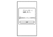
プロジェクター10Aから送信された機能情報を近距離通信部208が受信すると、制御部201は、近距離通信部208が受信した機能情報を取得する。制御部201は、機能情報を取得すると、プロジェクター10に接続したことをユーザーに通知するダイアログボックスが表示されるようにタッチパネル203を制御する(ステップSA7)。制御部201は、このダイアログボックスの表示に際し、取得した機能情報にネットワークスタンバイ機能を表す情報が含まれているか判断する。制御部201は、取得した機能情報がネットワークスタンバイ機能を表す情報を含む場合、プロジェクター10が電源オフのときにもリモコン機能を使用するかユーザーへ問い合わせるためのチェックボックスが表示されるようにタッチパネル203を制御する。
When the near
図9は、ここで情報処理装置20が表示するダイアログボックスの一例を示した図である。ユーザーが、表示されたチェックボックスをオンとする操作をタッチパネル203において行い、ダイアログボックス内にある「OK」ボタンをタップする操作を行うと、制御部201は、ネットワークスタンバイ機能を有効にするコマンドをプロジェクター10Aへ送信する(ステップSA8)。制御部201は、コマンドの送信が終了すると、図7に示したメニュー画面が表示されるようにタッチパネル203を制御する。
FIG. 9 is a diagram showing an example of the dialog box displayed by the
ネットワークスタンバイ機能を有効にするコマンドを通信部180Aが受信すると、制御部110Aは、通信部180Aが受信したコマンドを取得する。制御部110Aは、このコマンドを取得すると、ネットワークスタンバイ機能を有効に設定する(ステップSA9)。 When the communication unit 180A receives a command for enabling the network standby function, the control unit 110A acquires the command received by the communication unit 180A. When the control unit 110A acquires this command, it sets the network standby function to be effective (step SA9).
次に、ユーザーが、図7の画面を表示しているタッチパネル203において、「リモコン」の部分をタップする操作を行うと(ステップSA10)、制御部201は、ステップSA6で送信された機能情報にサーバー機能を表す情報が含まれているか判断する。上述したように、プロジェクター10Aから送信された機能情報には、サーバー機能を表す情報が含まれている。この場合、制御部201は、プロジェクターを操作するための操作画像の一例であるGUI画像のデータを要求するメッセージを、近距離通信部208を制御してプロジェクター10Aへ送信する(ステップSA11)。
Next, when the user performs an operation to tap the “remote control” portion on the
GUI画像のデータを要求するメッセージを通信部180Aが受信すると、制御部110Aは、通信部180Aが受信したメッセージを取得する。制御部110Aは、GUI画像のデータを要求するメッセージを取得すると、プロジェクター10Aの操作を行うためのGUI画像のデータを、通信部180Aを制御して情報処理装置20へ送信する(ステップSA12)。本実施形態においては、GUI画像のデータは、HTML(HyperText Markup Language)で記述されている。
When the communication unit 180A receives a message requesting data of a GUI image, the control unit 110A acquires the message received by the communication unit 180A. When acquiring the message requesting the data of the GUI image, the control unit 110A controls the communication unit 180A to transmit the data of the GUI image for operating the
プロジェクター10Aから送信されたGUI画像のデータを近距離通信部208が受信すると、制御部201は、近距離通信部208が受信したデータを取得する。制御部201は、取得したデータに従ってGUI画像を生成し、生成したGUI画像が表示されるようにタッチパネル203を制御する(ステップSA13)。
When the near
図10は、ここでタッチパネル203に表示されるGUI画像の一例を示した図である。図10において、表示領域A1は、コントロールアプリが予めリソースとして備えているコントロールの画像(共通操作画面)を表示する領域であり、表示領域A2は、GUI画像のデータ(第2共通操作画面情報の一例)に従って生成した画面を表示する領域である。表示領域A1内には、接続したプロジェクター10の識別子が表示される。表示領域A2内のボタンのGUIは、例えば、HTMLのbuttonタグにより実現することができる。
FIG. 10 is a view showing an example of a GUI image displayed on the
ユーザーが、タッチパネル203に表示された電源ボタンB11をタップする操作を行うと(ステップSA14)、制御部201は、GUI画像のHTMLデータにおいて、電源ボタンB11に対応するbuttonタグのvalue属性に記述されている文字列を取得する。例えば、電源ボタンB11については、ここでvalue属性として「power」という文字列が対応付けられている。この文字列は、プロジェクター10の電源をオン又はオフとする命令の一例である。制御部201は、近距離通信部208を制御し、取得した文字列をプロジェクター10Aへ送信する(ステップSA15)。
When the user performs an operation of tapping the power button B11 displayed on the touch panel 203 (step SA14), the
情報処理装置20から送信された「power」という文字列を通信部180Aが受信すると、制御部110Aは、通信部180Aが受信した文字列を取得する。制御部110Aは、「power」という文字列を取得すると、自装置の電源がオンの状態である場合、電源をオフとし、映像処理部150や投写部140への電力供給を停止するが、ネットワークスタンバイ機能を有効に設定している場合、通信部180Aについては電力の供給を停止しない(ステップSA16)。このため、プロジェクター10Aで電源がオフとなっても、プロジェクター10Aと情報処理装置20との間では通信のコネクションが確立したままとなる。
When the communication unit 180A receives the character string “power” transmitted from the
次に、ユーザーが、タッチパネル203に表示されている電源ボタンB11をタップする操作を行うと(ステップSA17)、制御部201は、GUI画像のHTMLデータにおいて、電源ボタンB11に対応するbuttonタグのvalue属性に記述されている文字列を取得する。制御部201は、近距離通信部208を制御し、取得した文字列(「power」)をプロジェクター10Aへ送信する(ステップSA18)。
Next, when the user performs an operation to tap the power button B11 displayed on the touch panel 203 (step SA17), the
情報処理装置20から送信された「power」という文字列を通信部180Aが受信すると、制御部110Aは、通信部180Aが受信した文字列を取得する。制御部110Aは、「power」という文字列を取得すると、自装置の電源がオフの状態である場合、電源をオンとし、電力供給が停止されていた部分への電力供給を行う(ステップSA19)。
When the communication unit 180A receives the character string “power” transmitted from the
次に、ネットワークスタンバイ機能を無効にした場合の動作例について、図11のシーケンス図を用いて説明する。なお、以下の説明においては、ステップSA1からステップSA7までの処理が既に行われているものとして動作例の説明を行う。 Next, an operation example when the network standby function is disabled will be described using the sequence diagram of FIG. In the following description, the operation example will be described on the assumption that the processing from step SA1 to step SA7 has already been performed.
図9の画面において、ユーザーが、表示されたチェックボックスをオフとする操作をタッチパネル203において行い、ダイアログボックス内にある「OK」ボタンをタップする操作を行うと、制御部201は、ネットワークスタンバイ機能を無効にするコマンドをプロジェクター10Aへ送信する(ステップSB1)。制御部201は、コマンドの送信が終了すると、図7の画面が表示されるようにタッチパネル203を制御する。
In the screen of FIG. 9, when the user performs an operation of turning off the displayed check box on the
ネットワークスタンバイ機能を無効にするコマンドを通信部180Aが受信すると、制御部110Aは、通信部180Aが受信したコマンドを取得する。制御部110Aは、このコマンドを取得すると、ネットワークスタンバイ機能を無効に設定する(ステップSB2)。 When the communication unit 180A receives a command to invalidate the network standby function, the control unit 110A acquires the command received by the communication unit 180A. When acquiring the command, control unit 110A sets the network standby function to be invalid (step SB2).
次に、ユーザーが、図7の画面を表示しているタッチパネル203において、「リモコン」の部分をタップする操作を行うと(ステップSB3)、情報処理装置20とプロジェクター10Aが通信を行い、上述した動作例のステップSA11〜ステップSA13と同じ処理が行われ、図10に示した画面がタッチパネル203に表示される(ステップSB4〜ステップSB6)。
Next, when the user performs an operation to tap the “remote control” portion on the
ユーザーが、タッチパネル203に表示されている電源ボタンB11をタップする操作を行うと(ステップSB7)、制御部201は、GUI画像のHTMLデータにおいて、電源ボタンB11に対応するbuttonタグのvalue属性に記述されている文字列を取得する。制御部201は、近距離通信部208を制御し、取得した文字列(「power」)をプロジェクター10Aへ送信する(ステップSB8)。
When the user performs an operation to tap the power button B11 displayed on the touch panel 203 (step SB7), the
情報処理装置20から送信された「power」という文字列を通信部180Aが受信すると、制御部110Aは、通信部180Aが受信した文字列を取得する。制御部110Aは、「power」という文字列を取得すると、自装置の電源がオンの状態である場合、電源をオフとし、映像処理部150や投写部140への電力供給を停止する。また、制御部110Aは、「power」という文字列を取得したときに、ネットワークスタンバイ機能を無効に設定している場合、通信部180Aについても電力の供給を停止する(ステップSB9)。通信部180Aへの電力供給が停止されるため、プロジェクター10Aと情報処理装置20との間では通信のコネクションが切断される。制御部201は、プロジェクター10Aとのコネクションが切断されると、図7の画面が表示されるようにタッチパネル203を制御する。
When the communication unit 180A receives the character string “power” transmitted from the
このように、ユーザーがネットワークスタンバイ機能を無効とした場合、電源をオフとすると通信部180Aへの電力供給が停止されるため、プロジェクター10Aは、IEEE802.11の規格に従った無線通信が不可となり、情報処理装置20は、無線通信によりプロジェクター10Aの電源をオンとすることができなくなる。この場合、プロジェクター10Aの電源をオンにするには、ユーザーは、リモートコントローラー又は操作部130Aの電源ボタンを操作し、プロジェクター10Aの電源をオンにする。
As described above, when the user deactivates the network standby function, the power supply to the communication unit 180A is stopped when the power is turned off, so that the
次に、ネットワークスタンバイ機能を備えていないプロジェクター10Bへ情報処理装置20が接続したときの動作例について、図12のシーケンス図を用いて説明する。なお、以下の説明においては、ステップSA1〜ステップSA2までの処理と同じ処理(ステップSC1〜ステップSC2)が既に行われているものとして動作例の説明を行う。
Next, an operation example when the
図8の画面が表示されている状態において、ユーザーが、プロジェクター10BのIPアドレスと識別子が表示されている行のチェックボックスをオンとする操作をタッチパネル203において行い、右上の「接続」ボタンをタップする操作を行うと(ステップSC3)、制御部201は、近距離通信部208を制御して無線通信を行い、プロジェクター10Bとの通信のコネクションを確立する(ステップSC4)。
In the state where the screen of FIG. 8 is displayed, the user performs an operation on the
制御部201は、プロジェクター10Bとのコネクションが確立すると、プロジェクター10Bが備える機能を問い合わるメッセージをプロジェクター10Bへ送信する(ステップSC5)。このメッセージを通信部180Bが受信すると、制御部110Bは、プロジェクター10Bが備える機能を表す機能情報を情報処理装置20へ送信する(ステップSC6)。プロジェクター10Bは、上述したようにサーバー機能を備えるものの、ネットワークスタンバイ機能を備えていないため、ここで情報処理装置20に送信される機能情報には、サーバー機能を表す情報が含まれ、ネットワークスタンバイ機能を表す情報が含まれないこととなる。
When the connection with the
プロジェクター10Bから送信された機能情報を近距離通信部208が受信すると、制御部201は、近距離通信部208が受信した機能情報を取得する。制御部201は、機能情報を取得すると、プロジェクター10に接続したことをユーザーに通知するダイアログボックスが表示されるようにタッチパネル203を制御する(ステップSC7)。制御部201は、このダイアログボックスの表示に際し、取得した機能情報にネットワークスタンバイ機能を表す情報が含まれているか判断する。制御部201は、取得した機能情報にネットワークスタンバイ機能を表す情報が含まれていない場合、プロジェクターが電源オフのときにもリモコン機能を使用するかユーザーへ問い合わせるためのチェックボックスが表示されないようにタッチパネル203を制御する。
When the near
図13は、ここで情報処理装置20が表示するダイアログボックスの一例を示した図である。ユーザーが、ダイアログボックス内にある「OK」ボタンをタップする操作を行うと(ステップSC8)、制御部201は、図7に示したメニュー画面が表示されるようにタッチパネル203を制御する(ステップSC9)。次に、ユーザーが、図7の画面を表示しているタッチパネル203において、「リモコン」の部分をタップする操作を行うと(ステップSC10)、制御部201は、ステップSC6で取得した機能情報にサーバー機能を表す情報が含まれているか判断する。上述したように、プロジェクター10Bから取得した機能情報には、サーバー機能を表す情報が含まれている。この場合、制御部201は、プロジェクターを操作するためのGUI画像のデータを要求するメッセージを、近距離通信部208を制御してプロジェクター10Bへ送信する(ステップSC11)。
FIG. 13 is a diagram showing an example of the dialog box displayed by the
情報処理装置20がGUI画像のデータを要求するメッセージを送信した後、GUI画像のデータを取得し、取得したデータに従ってGUI画像を表示するまでの動作(ステップSC12、ステップSC13)は、上述したプロジェクター10Aへ接続したときの動作例と同じであるため、その説明を省略する。
After the
次に、図10の画面がタッチパネル203に表示されている状態において、ユーザーが、表示されている電源ボタンB11をタップする操作を行うと(ステップSC14)、制御部201は、GUI画像のHTMLデータにおいて、電源ボタンB11に対応するbuttonタグのvalue属性に記述されている文字列を取得する。制御部201は、近距離通信部208を制御し、取得した文字列(「power」)をプロジェクター10Bへ送信する(ステップSC15)。
Next, in a state where the screen of FIG. 10 is displayed on the
情報処理装置20から送信された「power」という文字列を通信部180Bが受信すると、制御部110Bは、通信部180Bが受信した文字列を取得する。制御部110Bは、「power」という文字列を取得すると、自装置の電源がオンの状態である場合、電源をオフとし、映像処理部150や投写部140への電力供給を停止する。また、制御部110Bは、自装置がネットワークスタンバイ機能を備えていないため、通信部180Bについても電力の供給を停止する(ステップSC16)。通信部180Bへの電力供給が停止されるため、プロジェクター10Bと情報処理装置20との間では通信のコネクションが切断される。制御部201は、プロジェクター10Bとのコネクションが切断されると、図7の画面が表示されるようにタッチパネル203を制御する。
When the communication unit 180B receives the character string “power” transmitted from the
このようにネットワークスタンバイ機能を備えていないプロジェクター10Bへ接続した場合、電源をオフとすると通信部180Bへの電力供給が停止されるため、プロジェクター10Bは、IEEE802.11の規格に従った無線通信が不可となり、情報処理装置20は、無線通信によりプロジェクター10Bの電源をオンとすることができなくなる。この場合、プロジェクター10Bの電源をオンにするには、ユーザーは、リモートコントローラー又は操作部130Bの電源ボタンを操作し、プロジェクター10Bの電源をオンにする。
As described above, when the
次に、情報処理装置20がサーバー機能とネットワークスタンバイ機能を備えていないプロジェクター10Cに接続したときの動作例について、図14のシーケンス図を用いて説明する。なお、以下の説明においては、ステップSA1〜ステップSA2までの処理と同じ処理(ステップSD1〜ステップSD2)が既に行われているものとして動作例の説明を行う。
Next, an operation example when the
図8の画面が表示されている状態において、ユーザーが、プロジェクター10CのIPアドレスと識別子が表示されている行のチェックボックスをオンとする操作をタッチパネル203において行い、右上の「接続」ボタンをタップする操作を行うと(ステップSD3)、制御部201は、近距離通信部208を制御して無線通信を行い、プロジェクター10Cとの通信のコネクションを確立する(ステップSD4)。
In the state where the screen of FIG. 8 is displayed, the user performs an operation on the
制御部201は、プロジェクター10Cとのコネクションが確立すると、プロジェクター10Cが備える機能を問い合わるメッセージをプロジェクター10Cへ送信する(ステップSD5)。このメッセージを通信部180Cが受信すると、制御部110Cは、プロジェクター10Cが備える機能を表す機能情報を情報処理装置20へ送信する(ステップSD6)。プロジェクター10Cは、上述したようにサーバー機能及びネットワークスタンバイ機能を備えていないため、ここで、情報処理装置20に送信される機能情報には、サーバー機能を表す情報と、ネットワークスタンバイ機能を表す情報が含まれないこととなる。
When the connection with the
プロジェクター10Cから送信された機能情報を近距離通信部208が受信すると、制御部201は、近距離通信部208が受信した機能情報を取得する。制御部201は、機能情報を取得すると、プロジェクター10に接続したことをユーザーに通知するダイアログボックスが表示されるようにタッチパネル203を制御する(ステップSD7)。制御部201は、このダイアログボックスの表示に際し、取得した機能情報にネットワークスタンバイ機能を表す情報が含まれているか判断する。制御部201は、取得した機能情報にネットワークスタンバイ機能を表す情報が含まれていない場合、プロジェクターが電源オフのときにもリモコン機能を使用するかユーザーへ問い合わせるためのチェックボックスが表示されないようにタッチパネル203を制御する。
When the near
ユーザーが、ダイアログボックス内にある「OK」ボタンをタップする操作を行うと(ステップSD8)、制御部201は、図7に示したメニュー画面が表示されるようにタッチパネル203を制御する(ステップSD9)。次に、ユーザーが、図7の画面を表示しているタッチパネル203において、「リモコン」の部分をタップする操作を行うと(ステップSD10)、制御部201は、ステップSD6で取得した機能情報にサーバー機能を表す情報が含まれているか判断する。上述したように、プロジェクター10Cから取得した機能情報には、サーバー機能を表す情報が含まれていない。この場合、制御部201は、コントロールアプリが予めリソースとして備えている共通操作画面情報に応じた操作画面が表示されるように、タッチパネル203を制御する(ステップSD11)。前述したようにコントロールアプリは、記憶部202に記憶されているので、コントロールアプリが予めリソースとして備えている共通操作画面情報も記憶部202に記憶されている。即ち、記憶部202は、共通操作画面情報を記憶する記憶手段の一例である。また、第1共通操作画面情報は、記憶部202が記憶している共通操作画面情報の一例である。
When the user performs an operation to tap the “OK” button in the dialog box (step SD8), the
図15は、ここでタッチパネル203に表示されるGUI画像の一例を示した図である。図15において、表示領域A3は、コントロールアプリが予めリソースとして備えているボタンの画像を表示する領域である。ここで、表示されるGUI画像には、電源のオン/オフや映像ソースの切り替えなど、プロジェクター10A〜10Cに共通な操作のためのボタンが表示される。ユーザーが、表示されている電源ボタンB12をタップする操作をタッチパネル203において行うと(ステップSD12)、制御部201は、近距離通信部208を制御し、電源ボタンB12に対応付けられた「power」という文字列をプロジェクター10Cへ送信する(ステップSD13)。
FIG. 15 is a view showing an example of a GUI image displayed on the
情報処理装置20から送信された「power」という文字列を通信部180Cが受信すると、制御部110Cは、通信部180Cが受信した文字列を取得する。制御部110Cは、「power」という文字列を取得すると、自装置の電源がオンの状態である場合、電源をオフとし、映像処理部150や投写部140への電力供給を停止する。また、制御部110Cは、自装置がネットワークスタンバイ機能を備えていないため、通信部180Cについても電力の供給を停止する(ステップSD14)。通信部180Cへの電力供給が停止されるため、プロジェクター10Cと情報処理装置20との間では通信のコネクションが切断される。制御部201は、プロジェクター10Cとのコネクションが切断されると、図7の画面が表示されるようにタッチパネル203を制御する。
When the communication unit 180C receives the character string “power” transmitted from the
このように、サーバー機能を備えていないプロジェクター10Cへ情報処理装置20が接続しても、情報処理装置20は、プロジェクター10に共通な操作のためにコントロールアプリが予めリソースとして備えているGUI画像のデータに応じたGUI画像を表示し、無線通信によりプロジェクター10Cを操作することができる。
As described above, even when the
次に、プロジェクター10が投写する画像の画質設定を対話形式で行う場合の動作例について、図16のシーケンス図を用いて説明する。なお、以下の説明においては、情報処理装置20がプロジェクター10Aに接続されている場合を想定して動作例の説明を行う。
Next, an operation example in the case where the image quality setting of the image to be projected by the
図10のGUI画像がタッチパネル203に表示されている状態において、ユーザーが「かんたん画質設定」の部分をタップする操作を行うと(ステップSE1)、制御部201は、GUI画像のHTMLデータにおいて、タップされた部分に対応するbuttonタグのvalue属性に記述されている文字列を取得する。制御部201は、近距離通信部208を制御し、取得した文字列をプロジェクター10Aへ送信する(ステップSE2)。情報処理装置20から送信された文字列を通信部180Aが受信すると、制御部110Aは、通信部180Aが受信した文字列を取得し、取得した文字列に対応したGUI画像のデータを、通信部180Aを制御して情報処理装置20へ送信する(ステップSE3)。
When the user performs an operation to tap the “Easy image quality setting” portion while the GUI image of FIG. 10 is displayed on the touch panel 203 (step SE1), the
プロジェクター10Aから送信されたGUI画像のデータを近距離通信部208が受信すると、制御部201は、近距離通信部208が受信したデータを取得する。制御部201は、取得したデータに従ってGUI画像を生成し、生成したGUI画像が表示されるようにタッチパネル203を制御する(ステップSE4)。
When the near
図17は、ここでタッチパネル203に表示されるGUI画像の一例を示した図である。ユーザーが「スタート」の部分をタップする操作を行うと(ステップSE5)、制御部201は、GUI画像のHTMLデータにおいて、タップされた部分に対応するbuttonタグのvalue属性に記述されている文字列をプロジェクター10Aへ送信し(ステップSE6)、プロジェクター10Aは、送信された文字列に対応したGUI画像のデータを、通信部180Aを制御して情報処理装置20へ送信する(ステップSE7)。また、制御部110Aは、この時点での画質の設定に係るデータを、記憶部120Aに記憶させる(ステップSE8)。
FIG. 17 is a view showing an example of a GUI image displayed on the
プロジェクター10Aから送信されたGUI画像のデータを近距離通信部208が受信すると、制御部201は、近距離通信部208が受信したデータに従ってGUI画像を生成し、生成したGUI画像が表示されるようにタッチパネル203を制御する(ステップSE9)。
When the short
図18は、ここでタッチパネル203に表示されるGUI画像の一例を示した図である。ここで、ユーザーは、視聴する映像の内容を選択する。ユーザーが、「映画/ドラマ」、「スポーツ」、「ゲーム」、「その他」のいずれかの部分をタップする操作を行うと(ステップSE10)、制御部201は、GUI画像のHTMLデータにおいて、タップされた部分に対応するbuttonタグのvalue属性に記述されている文字列をプロジェクター10Aへ送信する(ステップSE11)。
FIG. 18 is a view showing an example of a GUI image displayed on the
情報処理装置20から送信された文字列を通信部180Aが受信すると、制御部110Aは、通信部180Aが受信した文字列を取得し、次に情報処理装置20で表示させるGUI画像のデータを、通信部180Aを制御して情報処理装置20へ送信する(ステップSE12)。また、制御部110Aは、取得した文字列に応じて、画質に関連する機能の設定を行う(ステップSE13)。例えば、制御部110Aは、「映画/ドラマ」の部分に対応した文字列を取得した場合、映像処理部150を制御してフレーム補間の機能をオンに設定し、「スポーツ」の部分に対応した文字列又は「その他」の部分に対応した文字列を取得した場合、映像処理部150を制御してフレーム補間の機能をオフに設定する。また、制御部110Aは、「ゲーム」の部分に対応した文字列を取得した場合、映像処理部150を制御してフレーム補間の機能をオフ、ノイズリダクションの機能をオフ、プログレッシブ変換の機能をオフに設定する。
When the communication unit 180A receives the character string transmitted from the
プロジェクター10Aから送信されたGUI画像のデータを近距離通信部208が受信すると、制御部201は、近距離通信部208が受信したデータに従ってGUI画像を生成し、生成したGUI画像が表示されるようにタッチパネル203を制御する(ステップSE14)。図19は、ここでタッチパネル203に表示されるGUI画像の一例を示した図である。ここで、ユーザーは、視聴環境を選択する。ユーザーが、「明るい」又は「暗い」の部分をタップする操作を行うと(ステップSE15)、制御部201は、GUI画像のHTMLデータにおいて、タップされた部分に対応するbuttonタグのvalue属性に記述されている文字列をプロジェクター10Aへ送信する(ステップSE16)。
When the short
情報処理装置20から送信された文字列を通信部180Aが受信すると、制御部110Aは、通信部180Aが受信した文字列を取得し、次に情報処理装置20で表示させるGUI画像のデータを、通信部180Aを制御して情報処理装置20へ送信する(ステップSE17)。また、制御部110Aは、取得した文字列に応じて、画質に関連する機能の設定を行う(ステップSE18)。例えば、制御部110Aは、「明るい」の部分に対応した文字列を取得した場合、カラーモードを「ダイナミック」に設定し、「暗い」の部分に対応した文字列を取得した場合、カラーモードを「シネマ」に設定する。記憶部120Aには、カラーモード毎に、予め明るさ、コントラスト、色の濃さ、色合い、シャープネスなどの設定値が記憶されており、制御部110は、設定したカラーモードに対応して予め記憶部120Aに記憶されている明るさ、コントラスト、色の濃さ、色合い、シャープネスなどの設定値を取得し、取得した設定値で映像処理部150を制御する。
When the communication unit 180A receives the character string transmitted from the
プロジェクター10Aから送信されたGUI画像のデータを近距離通信部208が受信すると、制御部201は、近距離通信部208が受信したデータに従ってGUI画像を生成し、生成したGUI画像が表示されるようにタッチパネル203を制御する(ステップSE19)。図20は、ここでタッチパネル203に表示されるGUI画像の一例を示した図である。ここで、ユーザーは、投写される画像の色合いを選択する(ステップSE20)。ユーザーが、「赤みを強く」、「標準」、「青みを強く」のいずれかの部分をタップする操作を行うと、制御部201は、GUI画像のHTMLデータにおいて、タップされた部分に対応するbuttonタグのvalue属性に記述されている文字列をプロジェクター10Aへ送信する(ステップSE21)。
When the short
情報処理装置20から送信された文字列を通信部180Aが受信すると、制御部110Aは、通信部180Aが受信した文字列を取得し、次に情報処理装置20で表示させるGUI画像のデータを、通信部180Aを制御して情報処理装置20へ送信する(ステップSE22)。また、制御部110Aは、取得した文字列に応じて映像処理部150Aを制御し、投写する画像の色温度の設定を行う(ステップSE23)。例えば、制御部110Aは、「赤みを強く」の部分に対応した文字列を取得した場合、例えば色温度を5500Kに設定し、「標準」の部分に対応した文字列を取得した場合、色温度を6500Kに設定し、「青みを強く」の部分に対応した文字列を取得した場合、色温度を8000Kに設定する。なお、これらの色温度は一例であり、他の色温度であってもよい。
When the communication unit 180A receives the character string transmitted from the
プロジェクター10Aから送信されたGUI画像のデータを近距離通信部208が受信すると、制御部201は、近距離通信部208が受信したデータに従ってGUI画像を生成し、生成したGUI画像が表示されるようにタッチパネル203を制御する(ステップSE24)。図21は、ここでタッチパネル203に表示されるGUI画像の一例を示した図である。ここで、ユーザーは、投写される画像のくっきり感(エッジや輪郭の質感)を選択する(ステップSE25)。ユーザーが、「強め」、「標準」、「弱め」のいずれかの部分をタップする操作を行うと、制御部201は、GUI画像のHTMLデータにおいて、タップされた部分に対応するbuttonタグのvalue属性に記述されている文字列をプロジェクター10Aへ送信する(ステップSE26)。
When the short
情報処理装置20から送信された文字列を通信部180Aが受信すると、制御部110Aは、通信部180Aが受信した文字列を取得する。制御部110Aは、取得した文字列に応じて映像処理部150Aを制御し、投写する画像のエッジや輪郭の強調度合いの設定を行う(ステップSE27)。例えば、制御部110Aは、「強め」の部分に対応した文字列を取得した場合、エッジや輪郭の強調機能をオフに設定し、「標準」の部分に対応した文字列を取得した場合、エッジや輪郭の強調機能をオンとし、強調度合いを「標準」に対応した度合いに設定し、「弱め」の部分に対応した文字列を取得した場合、エッジや輪郭の強調機能をオンとし、強調度合いを「弱め」に対応した度合いに設定する。
When the communication unit 180A receives the character string transmitted from the
次に制御部110Aは、ユーザーが行った設定を確認するためのGUI画像のデータを、図18〜図21の画面の操作に応じて情報処理装置20から送られた文字列に基づいて生成し、生成したデータを情報処理装置20へ送信する(ステップSE28)。プロジェクター10Aから送信されたGUI画像のデータを近距離通信部208が受信すると、制御部201は、近距離通信部208が受信したデータに従ってGUI画像を生成し、生成したGUI画像が表示されるようにタッチパネル203を制御する(ステップSE29)。
Next, the control unit 110A generates data of a GUI image for confirming the setting made by the user based on the character string sent from the
図22は、ここでタッチパネル203に表示されるGUI画像の一例を示した図である。図22に示したように、図18〜図21の画面においてユーザーが選択した項目がタッチパネル203に表示され、ユーザーは、自身が行った設定の内容を確認することができる。ユーザーは、投写されている画像を視聴し、設定された画質を確認する。本実施形態によれば、対話形式で画像に係る各種設定を行い、設定結果を見て確認できるため、ユーザーの好みの画質に簡単に設定することができる。
FIG. 22 is a diagram showing an example of a GUI image displayed on the
次に、設定した画質設定を記憶させない場合の動作例と、設定した画質設定を記憶させる場合の動作例について、図23〜25を用いて説明する。
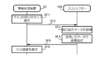
ユーザーは、設定した画質が好みの画質ではない場合、画面にある「中止」の部分をタップする操作を行う(ステップSF1)。この操作が行われると、制御部201は、GUI画像のHTMLデータにおいて、タップされた部分に対応するbuttonタグのvalue属性に記述されている文字列をプロジェクター10Aへ送信する(ステップSF2)。
Next, an operation example when the set image quality setting is not stored and an operation example when the set image quality setting is stored will be described with reference to FIGS.
When the set image quality is not the desired image quality, the user performs an operation of tapping the “stop” part on the screen (step SF1). When this operation is performed, the
情報処理装置20から送信された文字列を通信部180Aが受信すると、制御部110Aは、通信部180Aが受信した文字列を取得する。制御部110Aは、取得した文字列が、「中止」の部分に対応した文字列である場合、画質の設定前にステップSE8で記憶したデータを記憶部120Aから取得する(ステップSF3)。制御部110Aは、取得したデータに基づいて映像処理部150Aを制御し、投写する画像の画質を図17〜図20の設定が行われる前の状態に戻す(ステップSF4)。
制御部110Aは、ステップSF4の処理が終了すると、図10のGUI画像のデータを情報処理装置20へ送信する(ステップSF5)。プロジェクター10Aから送信されたGUI画像のデータを近距離通信部208が受信すると、制御部201は、近距離通信部208が受信したデータに従ってGUI画像を生成し、生成したGUI画像が表示されるようにタッチパネル203を制御する(ステップSF6)。
このように本実施形態によれば、対話形式で設定した画質が好みの画質ではない場合、ユーザーは、設定を行う前の画質に容易に戻すことができる。
When the communication unit 180A receives the character string transmitted from the
When the process of step SF4 is completed, the control unit 110A transmits the data of the GUI image of FIG. 10 to the information processing apparatus 20 (step SF5). When the short
As described above, according to the present embodiment, when the image quality set in the interactive mode is not the desired image quality, the user can easily return to the image quality before setting.
一方、ユーザーは、設定した画質が好みの画質である場合、自身が行った設定をプロジェクター10Aに記憶させるか否か選択する。ユーザーは、自身が行った設定をプロジェクター10Aに記憶させる場合、図22の画面が表示されているタッチパネル203において「保存する」の部分をタップする(図24:ステップSG1)。この操作が行われると、制御部201は、GUI画像のHTMLデータにおいて、タップされた部分に対応するbuttonタグのvalue属性に記述されている文字列をプロジェクター10Aへ送信する(ステップSG2)。
On the other hand, when the set image quality is a desired image quality, the user selects whether to store the setting made by the user in the
情報処理装置20から送信された文字列を通信部180Aが受信すると、制御部110Aは、通信部180Aが受信した文字列を取得する。制御部110Aは、「保存する」の部分に対応した文字列を取得した場合、図18〜図21の画面で行われた画質設定に係るデータを、記憶部120Aに記憶させる(ステップSG3)。制御部110Aは、データの記憶が終了すると、図10のGUI画像のデータを情報処理装置20へ送信する(ステップSG4)。プロジェクター10Aから送信されたGUI画像のデータを近距離通信部208が受信すると、制御部201は、近距離通信部208が受信したデータを取得する。制御部201は、取得したデータに従ってGUI画像を生成し、生成したGUI画像が表示されるようにタッチパネル203を制御する(ステップSG5)。
When the communication unit 180A receives the character string transmitted from the
この後、ユーザーが、リモートコントローラー又は操作部130Aを操作して画質を変更すると(ステップSG6)、図17〜図20の画面で設定した画質とは異なる画質となる。画質が変更された後、ユーザーが図10の画面が表示されているタッチパネル203において「メモリー」と表示されている部分をタップする操作を行うと(ステップSG7)、制御部201は、GUI画像のHTMLデータにおいて、タップされた部分に対応するbuttonタグのvalue属性に記述されている文字列をプロジェクター10Aへ送信する(ステップSG8)。情報処理装置20から送信された文字列を通信部180Aが受信すると、制御部110Aは、通信部180Aが受信した文字列を取得する。制御部110Aは、取得した文字列が、「メモリー」の部分に対応した文字列である場合、ステップSG3で記憶したデータを記憶部120Aから取得する(ステップSG9)。制御部110Aは、取得したデータに基づいて映像処理部150Aを制御し、投写する画像の画質を、ステップSG3でデータを記憶したときの画質に変更する(ステップSG10)。
このように本実施形態によれば、対話形式で設定した画質から画質を変更しても、対話形式で設定した画質に容易に戻すことができる。
After that, when the user operates the remote controller or the operation unit 130A to change the image quality (step SG6), the image quality becomes different from the image quality set on the screens of FIGS. After the image quality is changed, when the user performs an operation of tapping a portion displayed as “memory” on the
As described above, according to the present embodiment, even if the image quality is changed from the image quality set in the interactive mode, it is possible to easily restore the image quality set in the interactive mode.
また、ユーザーは、設定した画質が好みの画質であるものの、自身が行った設定をプロジェクター10Aに記憶させない場合、図22の画面が表示されているタッチパネル203において「保存しない」の部分をタップする操作を行う(ステップSH1)。この操作が行われると、制御部201は、GUI画像のHTMLデータにおいて、タップされた部分に対応するbuttonタグのvalue属性に記述されている文字列をプロジェクター10Aへ送信する(ステップSH2)。
In addition, the user taps the “do not save” portion on the
情報処理装置20から送信された文字列を通信部180Aが受信すると、制御部110Aは、通信部180Aが受信した文字列を取得する。制御部110Aは、「保存しない」の部分に対応した文字列を取得した場合、図18〜図21の画面で行われた画質設定に係るデータを記憶部120Aに記憶させず、図10のGUI画像のデータを情報処理装置20へ送信する(ステップSH3)。プロジェクター10Aから送信されたGUI画像のデータを近距離通信部208が受信すると、制御部201は、近距離通信部208が受信したデータを取得する。制御部201は、取得したデータに従ってGUI画像を生成し、生成したGUI画像が表示されるようにタッチパネル203を制御する(ステップSH4)。
When the communication unit 180A receives the character string transmitted from the
[変形例]
以上、本発明の実施形態について説明したが、本発明は上述した実施形態に限定されることなく、他の様々な形態で実施可能である。例えば、上述の実施形態を以下のように変形して本発明を実施してもよい。なお、上述した各実施形態及び以下の変形例は、一つ又は複数を適宜組み合わせて実施してもよい。
[Modification]
Although the embodiments of the present invention have been described above, the present invention is not limited to the above-described embodiments, and can be practiced in various other forms. For example, the above-described embodiment may be modified as follows to implement the present invention. In addition, each embodiment mentioned above and the following modifications may be implemented combining suitably one or more.
上述した実施形態においては、情報処理装置20は、プロジェクター10と接続した後、接続したプロジェクター10の識別子を表示領域A1に表示しているが、識別子が表示されているテキストボックスに他のプロジェクター10の識別子をユーザーが入力すると、情報処理装置20は、入力された識別子のプロジェクター10へ接続先を変更するようにしてもよい。
In the embodiment described above, after connecting to the
本発明においては、情報処理装置20に記憶されている静止画又は動画の画像データを情報処理装置20から接続先のプロジェクター10へ送信し、プロジェクター10は、情報処理装置20から送信された画像データが表す画像(コンテンツ)を投写してもよい。情報処理装置20から画像データを送信してプロジェクター10で画像を投写する際には、画像データを選択するGUIを表示領域A1に設け、GUIへの操作に応じて画像データを選択し、投写する画像を変更するようにしてもよい。
また、この構成においては、選択した画像データの画像を表示領域A1に表示するようにしてもよい。選択した画像データの画像を表示領域A1に表示する際には、表示領域A1の大きさを図10に示した大きさより大きくする。
また、表示領域A1の大きさを変更する際には、表示領域A1のサイズを表す情報を情報処理装置20からプロジェクター10へ送信し、プロジェクター10は、送信されたサイズに合わせたGUI画像のデータを生成して情報処理装置20へ送信し、情報処理装置20は、送信されたGUI画像のデータに基づいて、表示領域A2へGUI画像を表示してもよい。
In the present invention, the image data of a still image or a moving image stored in the
In this configuration, the image of the selected image data may be displayed in the display area A1. When the image of the selected image data is displayed on the display area A1, the size of the display area A1 is made larger than the size shown in FIG.
Further, when changing the size of the display area A1, the information representing the size of the display area A1 is transmitted from the
本発明においては、プロジェクター10は、情報処理装置20とコネクションを確立した後、電源がオンの状態のときにコネクションが切れた場合、電源をオフにするようにしてもよい。また、プロジェクター10は、ネットワークスタンバイが有効の設定のときに情報処理装置20とコネクションを確立すると、電源をオンとしてもよい。
In the present invention, after the connection with the
上述した実施形態においては、プロジェクター10は、機能情報を情報処理装置20へ送信するときに、ネットワークスタンバイ機能の設定状態を含めるようにし、情報処理装置20は、図9のダイアログボックスを表示する際に、チェックボックスのオン/オフの表示を機能情報に含まれていたネットワークスタンバイ機能の設定状態に応じて行うようにしてもよい。
In the embodiment described above, when transmitting the function information to the
本発明においては、電源がオンのプロジェクター10と情報処理装置20との間でコネクションが確立して情報処理装置20が図10の画面を表示しているときに操作部130又はリモートコントローラーでプロジェクター10の電源をオフとした場合、情報処理装置20は、コネクションの切断に応じて、図7の画面を表示してもよい。
In the present invention, when a connection is established between the
上述した実施形態においては、対話形式で画質の設定を行う際、視聴する映像を選択した後、視聴環境を選択した後、色合いを選択した後、くっきり感を選択した後のそれぞれで映像処理部150を制御し、画質を変更しているが、この構成に限定されるものではない。例えば、視聴する映像、視聴環境、色合い、くっきり感の全てを選択し終えた後に、選択された項目に応じて映像処理部150を制御して画質を変更してもよい。
In the embodiment described above, when setting the image quality in an interactive mode, after selecting the image to be viewed, and then selecting the viewing environment, and after selecting the color tone, the image processing section after selecting the crispness Although 150 is controlled to change the image quality, it is not limited to this configuration. For example, the image to be viewed, the viewing environment, color, after it has finished selecting all sharp sensitive, may change the picture quality by controlling the
視聴環境に応じて設定するカラーモードは、映像信号が2D画像の場合と3D画像の場合とで異なるようにしてもよい。具体的には、制御部110は、投写する画像を表す映像信号が2D画像の信号と3D画像の信号のいずれであるか判定する。例えば、制御部110は、投写する画像の信号が2D画像の信号である場合、ユーザーが視聴環境として「明るい」を選択すると、カラーモードを「ブライトシネマ」とし、「暗い」を選択すると、カラーモードを「シネマ」とし、投写する画像の信号が3D画像の信号である場合、ユーザーが視聴環境として「明るい」を選択すると、カラーモードを「3Dダイナミック」とし、「暗い」を選択すると、カラーモードを「3Dシネマ」としてもよい。
The color mode set according to the viewing environment may be different between when the video signal is a 2D image and when it is a 3D image. Specifically, the
本発明においては、プロジェクター10が、無線LANを介して送られた画像データの画像を投写している場合、対話形式で行う画質設定の項目を、上述の実施形態とは異なる項目としてもよい。例えば、まず、一つ目のステップで映像の投写面を「スクリーン」、「ホワイトボード」、「黒板」の中から選択する構成とする。ここで、「スクリーン」が選択された場合、投写する画面の明るさを予め定められた第1の明るさとし、「ホワイトボード」が選択された場合、投写する画面の明るさを予め定められた第2の明るさとし、「黒板」が選択された場合、カラーモードを予め定められたモードに設定する。
また、次のステップでは、投写する映像の内容を「ビジネス文書」、「写真」、「Webページ」の中から選択する構成とする。ここで、「ビジネス文書」が選択された場合、カラーモードを「プレゼンテーション」、シャープネスを予め定められた設定値とし、
「写真」が選択された場合、カラーモードを「ダイナミック」とし、「Webページ」が選択された場合、カラーモードを「ダイナミック」、シャープネスを予め定められた設定値とする。
In the present invention, when the
In the next step, the contents of the image to be projected are selected from "business document", "photograph" and "web page". Here, when “business document” is selected, the color mode is “presentation”, and the sharpness is a preset setting value,
When "photo" is selected, the color mode is set to "dynamic", and when "web page" is selected, the color mode is set to "dynamic" and sharpness is set to a predetermined setting value.
本発明においては、対話形式で画質を設定する際に過去の操作履歴を記憶し、記憶した操作履歴に基づいて図18〜図21の画面で表示する項目の順番を変更するようにしてもよい。例えば、各画面においては、選択項目の表示位置を、過去に選択された回数に応じて降順に並べて表示するようにしてもよい。 In the present invention, when setting the image quality in an interactive manner, the past operation history may be stored, and the order of items displayed on the screens of FIGS. 18 to 21 may be changed based on the stored operation history. . For example, on each screen, the display position of the selection item may be arranged in descending order according to the number of times of selection in the past.
上述した実施形態においては、画像を投写する装置は、透過型の液晶パネルを用いた液晶プロジェクターとなっているが、反射型の液晶パネルやデジタルミラーデバイスを用いたプロジェクターでもよい。また、上述した実施形態においては、情報処理装置20から送られた画像データを受信して画像を表示するのは、プロジェクター10に限定されるものではなく、例えば、液晶テレビなどの直視型のディスプレイ装置であってもよい。
In the above-described embodiment, the apparatus for projecting an image is a liquid crystal projector using a transmissive liquid crystal panel, but a projector using a reflective liquid crystal panel or a digital mirror device may be used. Further, in the embodiment described above, it is not limited to the
上述した実施形態においては、
プロジェクター10と情報処理装置20との間で行われる通信は、IEEE802.11の規格に従った無線通信であるが、Bluetooth(登録商標)の規格に従った通信や、赤外光による通信など、他の無線通信の規格に従った通信であってもよい。
In the embodiment described above,
Communication performed between the
コントローラーアプリは、プロジェクター10の機種名と当該機種名が備える機能とを対応付けたテーブルを有する構成としてもよい。この構成の場合、情報処理装置20は、コネクションを確立したプロジェクター10から機種名を取得し、当該テーブルと、取得した機種名から接続先のプロジェクター10の機能を特定してもよい。
The controller application may be configured to have a table in which the model name of the
本発明に係る機能を実現するプログラムは、磁気記録媒体(磁気テープ、磁気ディスク(HDD(Hard Disk Drive)、FD(Flexible Disk))など)、光記録媒体(光ディスクなど)、光磁気記録媒体、半導体メモリーなどのコンピュータ読み取り可能な記録媒体に記憶した状態で提供し、各装置にインストールしてもよい。また、通信網を介してプログラムをダウンロードして各装置にインストールしてもよい。 Programs for realizing the functions according to the present invention include magnetic recording media (magnetic tape, magnetic disk (HDD (Hard Disk Drive), FD (Flexible Disk), etc.)), optical recording media (optical disks, etc.), magneto-optical recording media, It may be provided in the state of being stored in a computer readable recording medium such as a semiconductor memory and installed in each device. Also, the program may be downloaded via a communication network and installed in each device.
10、10A〜10C…プロジェクター、20…情報処理装置、110…制御部、120…記憶部、130…操作部、140…投写部、141…光源、142…ライトバルブ、143…投写光学系、144…駆動回路、150…映像処理部、160…映像インターフェース、180…通信部、201…制御部、202…記憶部、203…タッチパネル、205…通信部、207…音声処理部、208…近距離通信部、1001…第1制御部、1002…第2制御部、1003…機能情報送信部、1004…設定情報受信部、1005…操作画面情報送信部、1006…選択肢受信部、1007…画質設定部、2001…機能情報受信部、2002…表示制御部、2003…設定情報送信部、2004…命令送信部、2005…操作画面情報受信部、2006…要求部
10, 10A to 10C: projector, 20: information processing device, 110: control unit, 120: storage unit, 130: operation unit, 140: projection unit, 141: light source, 142: light valve, 143: projection optical system, 144 ... Drive circuit, 150 ... Video processing unit, 160 ... Video interface, 180 ... Communication unit, 201 ... Control unit, 202 ... Storage unit, 203 ... Touch panel, 205 ... Communication unit, 207 ... Audio processing unit, 208 ... Near field communication Section 1001: first control section 1002: second control section 1003: function information transmission section 1004: setting information reception section 1005: operation screen information transmission section 1006: option reception section 1007: image
Claims (5)
前記映像信号が表す画像を表示する表示手段と、
情報処理装置と接続して通信を行う通信手段と、
前記画像の画質を設定するための選択肢を有する複数の対話形式の設定画面に関する情報を、前記通信手段を介して前記情報処理装置へ送信する送信手段と、
前記情報処理装置において前記設定画面でユーザーが選択した選択肢を受信する受信手段と、
前記受信手段が受信した選択肢と、前記映像信号の種別とに応じて前記画質を設定する設定手段と、
を備え、
前記受信手段は、前記情報処理装置が、一の前記設定画面において選択肢の選択が終了する毎に送信する選択肢を受信し、
前記設定手段は、前記受信手段が前記選択肢を受信する毎に、受信した選択肢に応じて前記画質を設定し、
前記表示手段は、前記設定画面を介して前記設定手段が前記画質を設定する毎に、当該設定された画質で前記画像を表示する
表示装置。 Video signal acquisition means for acquiring a video signal;
Display means for displaying an image represented by the video signal;
Communication means connected to the information processing apparatus for communication;
A transmitting unit that transmits information related to a plurality of interactive setting screens having options for setting the image quality of the image to the information processing apparatus via the communication unit ;
A receiving unit configured to receive an option selected by the user on the setting screen in the information processing apparatus;
Setting means for setting the image quality according to the option received by the reception means and the type of the video signal;
Equipped with
The receiving unit receives an option to be transmitted by the information processing apparatus each time selection of an option is completed on the one setting screen,
The setting means sets the image quality according to the received option every time the receiving means receives the option.
The display unit displays the image with the set image quality each time the setting unit sets the image quality via the setting screen .
請求項1に記載の表示装置。 The display device according to claim 1, wherein the image quality set by the setting unit is different between the case where the type of the video signal is a 2D image and the case where the option is a 3D image even if the option received by the reception unit is the same.
前記設定画面の内容を前記履歴に応じて変更する変更手段
を備える請求項1又は2に記載の表示装置。 It has storage means for storing a history of selected options for each setting screen,
The display device according to claim 1 or 2 comprising a changing means for changing in accordance with the contents of the setting screen to the history.
請求項3に記載の表示装置。 The display device according to claim 3 , wherein the changing unit changes the order in which the options are arranged.
前記映像信号が表す画像を表示する表示手段と、
情報処理装置と接続して通信を行う通信手段と
を有する表示装置の画質設定方法であって、
前記画像の画質を設定するための選択肢を有する複数の対話形式の設定画面に関する情報を、前記通信手段を介して前記情報処理装置へ送信する送信ステップと、
前記情報処理装置において前記設定画面でユーザーが選択した選択肢を受信する受信ステップと、
前記受信ステップで受信した選択肢と、前記映像信号の種別とに応じて前記画質を設定する設定ステップと、
を備え、
前記受信ステップにおいて、前記情報処理装置が、一の前記設定画面において選択肢の選択が終了する毎に送信する選択肢を受信し、
前記設定ステップにおいて、受信した選択肢に応じて前記画質が設定され、
前記表示手段は、前記設定画面を介して前記画質が設定される毎に、当該設定された画質で前記画像を表示する
画質設定方法。 Video signal acquisition means for acquiring a video signal;
Display means for displaying an image represented by the video signal;
A method of setting image quality of a display device comprising: communication means connected to an information processing device to perform communication;
Transmitting, to the information processing apparatus via the communication means, information on a plurality of interactive setting screens having options for setting the image quality of the image;
A receiving step of receiving an option selected by the user on the setting screen in the information processing apparatus;
A setting step of setting the image quality according to the option received in the receiving step and the type of the video signal;
Equipped with
In the receiving step, the information processing apparatus receives an option to be transmitted each time selection of an option is completed on the one setting screen,
In the setting step, the image quality is set according to the received option.
The image quality setting method , wherein the display means displays the image with the set image quality each time the image quality is set via the setting screen .
Priority Applications (3)
| Application Number | Priority Date | Filing Date | Title |
|---|---|---|---|
| JP2015109842A JP6520406B2 (en) | 2015-05-29 | 2015-05-29 | Display device and image quality setting method |
| US15/161,607 US20160353096A1 (en) | 2015-05-29 | 2016-05-23 | Display device and image quality setting method |
| CN201610365936.3A CN106210920A (en) | 2015-05-29 | 2016-05-27 | Display device and image quality establishing method |
Applications Claiming Priority (1)
| Application Number | Priority Date | Filing Date | Title |
|---|---|---|---|
| JP2015109842A JP6520406B2 (en) | 2015-05-29 | 2015-05-29 | Display device and image quality setting method |
Publications (3)
| Publication Number | Publication Date |
|---|---|
| JP2016224225A JP2016224225A (en) | 2016-12-28 |
| JP2016224225A5 JP2016224225A5 (en) | 2018-06-07 |
| JP6520406B2 true JP6520406B2 (en) | 2019-05-29 |
Family
ID=57399437
Family Applications (1)
| Application Number | Title | Priority Date | Filing Date |
|---|---|---|---|
| JP2015109842A Active JP6520406B2 (en) | 2015-05-29 | 2015-05-29 | Display device and image quality setting method |
Country Status (3)
| Country | Link |
|---|---|
| US (1) | US20160353096A1 (en) |
| JP (1) | JP6520406B2 (en) |
| CN (1) | CN106210920A (en) |
Families Citing this family (6)
| Publication number | Priority date | Publication date | Assignee | Title |
|---|---|---|---|---|
| JP6631181B2 (en) * | 2015-11-13 | 2020-01-15 | セイコーエプソン株式会社 | Image projection system, projector, and method of controlling image projection system |
| JPWO2018155234A1 (en) * | 2017-02-24 | 2019-12-19 | ソニー株式会社 | Control device, control method, program, and projection system |
| US10264231B2 (en) * | 2017-03-31 | 2019-04-16 | The Directv Group, Inc. | Dynamically scaling the color temperature and luminance of a display output |
| CN110998669B (en) * | 2017-08-08 | 2023-12-08 | 索尼公司 | Image processing apparatus and method |
| CN109743516A (en) * | 2019-01-16 | 2019-05-10 | 四川长虹电器股份有限公司 | The multiplex system and method for different control signals under the identical port organization of television set |
| CN113939798A (en) * | 2019-06-13 | 2022-01-14 | 夏普Nec显示器解决方案株式会社 | Video display system, information processing device, video display method, and program |
Family Cites Families (20)
| Publication number | Priority date | Publication date | Assignee | Title |
|---|---|---|---|---|
| US8031891B2 (en) * | 2005-06-30 | 2011-10-04 | Microsoft Corporation | Dynamic media rendering |
| JP4725255B2 (en) * | 2005-09-07 | 2011-07-13 | セイコーエプソン株式会社 | Image display device, projector, parameter set selection method, and parameter set storage method |
| JP2008170671A (en) * | 2007-01-11 | 2008-07-24 | Seiko Epson Corp | Projector provided with projector body and remote controller, remote controller, projector body, image display device body, and image display device provided with remote controller |
| JP4382132B2 (en) * | 2007-06-29 | 2009-12-09 | シャープ株式会社 | Image display device |
| JP2009253890A (en) * | 2008-04-10 | 2009-10-29 | Seiko Epson Corp | Display system and image display device |
| JP4596193B2 (en) * | 2008-08-08 | 2010-12-08 | セイコーエプソン株式会社 | Projector, program, information storage medium, and data update method |
| JP4788748B2 (en) * | 2008-09-04 | 2011-10-05 | ソニー株式会社 | Video display device, video display method and system |
| KR20100031187A (en) * | 2008-09-12 | 2010-03-22 | 삼성전자주식회사 | Display apparatus, remote controller, display system and control method |
| JP4693918B2 (en) * | 2009-06-30 | 2011-06-01 | 株式会社東芝 | Image quality adjusting apparatus and image quality adjusting method |
| US8823782B2 (en) * | 2009-12-31 | 2014-09-02 | Broadcom Corporation | Remote control with integrated position, viewer identification and optical and audio test |
| JP5081934B2 (en) * | 2010-02-05 | 2012-11-28 | 京セラドキュメントソリューションズ株式会社 | Display input device and image forming apparatus having the same |
| JP4902795B2 (en) * | 2010-03-25 | 2012-03-21 | シャープ株式会社 | Display device, television receiver, display device control method, program, and recording medium |
| CN201898643U (en) * | 2010-11-03 | 2011-07-13 | 中航华东光电有限公司 | LED backlight brightness control device for stereoscopic display |
| CN102130900A (en) * | 2010-12-26 | 2011-07-20 | 青岛海信宽带多媒体技术有限公司 | Method and device for realizing three-screen interaction |
| CN102662360B (en) * | 2012-04-12 | 2014-01-22 | 南昌大学 | Wireless control system and method for remote device |
| JP2014045232A (en) * | 2012-08-24 | 2014-03-13 | Hitachi Consumer Electronics Co Ltd | Remote control system and terminal device |
| KR101978743B1 (en) * | 2012-10-19 | 2019-08-29 | 삼성전자주식회사 | Display device, remote controlling device for controlling the display device and method for controlling a display device, server and remote controlling device |
| US9182890B2 (en) * | 2013-01-31 | 2015-11-10 | Lg Electronics Inc. | Image display apparatus and method for operating the same |
| JP2015095750A (en) * | 2013-11-12 | 2015-05-18 | 株式会社東芝 | Electronic apparatus, method and program |
| CN103686350A (en) * | 2013-12-27 | 2014-03-26 | 乐视致新电子科技(天津)有限公司 | Method and system for adjusting image quality |
-
2015
- 2015-05-29 JP JP2015109842A patent/JP6520406B2/en active Active
-
2016
- 2016-05-23 US US15/161,607 patent/US20160353096A1/en not_active Abandoned
- 2016-05-27 CN CN201610365936.3A patent/CN106210920A/en active Pending
Also Published As
| Publication number | Publication date |
|---|---|
| JP2016224225A (en) | 2016-12-28 |
| CN106210920A (en) | 2016-12-07 |
| US20160353096A1 (en) | 2016-12-01 |
Similar Documents
| Publication | Publication Date | Title |
|---|---|---|
| JP6520406B2 (en) | Display device and image quality setting method | |
| JP6439590B2 (en) | Display system, information processing apparatus, program, and power supply control method | |
| JP5906779B2 (en) | Image display device | |
| TWI660304B (en) | Virtual reality real-time navigation method and system | |
| EP3225903B1 (en) | Intelligent projection light bulb and interactive and intelligent projection method thereof | |
| CN112073865B (en) | Volume setting method and device of Bluetooth headset and electronic equipment | |
| JP6340792B2 (en) | Video display system, connection method according to video wireless transmission standard between video transmission device and video reception display device constituting video display system, video transmission device and video reception display device | |
| JP4150295B2 (en) | Projection type image display device | |
| JP2016224662A5 (en) | ||
| JP6747025B2 (en) | Display system, display device, and control method for display system | |
| JP2010176020A (en) | Image display device, image display system and program | |
| JP6582560B2 (en) | Information processing apparatus, operation screen display method, and program | |
| KR102159816B1 (en) | Apparatus and method for playing back tangible multimedia contents | |
| JP6624270B2 (en) | Display system, information processing device, program, and power control method | |
| JP2009282431A (en) | Projector, image display device, and image display control device | |
| JP6379938B2 (en) | Information processing apparatus, display method, program, and display system | |
| JP2020057329A (en) | Guide system | |
| JP6428071B2 (en) | Video display system, connection method according to video wireless transmission standard between video transmission device and head-mounted display device constituting video display system, computer program, head-mounted display device | |
| JP2010088032A (en) | Remote control system | |
| JP2016163294A (en) | Display device and display method | |
| US11457265B2 (en) | Display device, display method, projector, and recording medium | |
| JP2011186364A (en) | Image display system, image display device and image display method | |
| CN102547445A (en) | Electronic equipment and program | |
| JP2009284390A (en) | Image display control device and method | |
| JP2005292500A (en) | Display apparatus, method, and program |
Legal Events
| Date | Code | Title | Description |
|---|---|---|---|
| A521 | Request for written amendment filed |
Free format text: JAPANESE INTERMEDIATE CODE: A523 Effective date: 20180417 |
|
| A621 | Written request for application examination |
Free format text: JAPANESE INTERMEDIATE CODE: A621 Effective date: 20180417 |
|
| A977 | Report on retrieval |
Free format text: JAPANESE INTERMEDIATE CODE: A971007 Effective date: 20181009 |
|
| A131 | Notification of reasons for refusal |
Free format text: JAPANESE INTERMEDIATE CODE: A131 Effective date: 20181023 |
|
| A521 | Request for written amendment filed |
Free format text: JAPANESE INTERMEDIATE CODE: A523 Effective date: 20181217 |
|
| TRDD | Decision of grant or rejection written | ||
| A01 | Written decision to grant a patent or to grant a registration (utility model) |
Free format text: JAPANESE INTERMEDIATE CODE: A01 Effective date: 20190402 |
|
| A61 | First payment of annual fees (during grant procedure) |
Free format text: JAPANESE INTERMEDIATE CODE: A61 Effective date: 20190415 |
|
| R150 | Certificate of patent or registration of utility model |
Ref document number: 6520406 Country of ref document: JP Free format text: JAPANESE INTERMEDIATE CODE: R150 |