JP2009282431A - Projector, image display device, and image display control device - Google Patents
Projector, image display device, and image display control device Download PDFInfo
- Publication number
- JP2009282431A JP2009282431A JP2008136388A JP2008136388A JP2009282431A JP 2009282431 A JP2009282431 A JP 2009282431A JP 2008136388 A JP2008136388 A JP 2008136388A JP 2008136388 A JP2008136388 A JP 2008136388A JP 2009282431 A JP2009282431 A JP 2009282431A
- Authority
- JP
- Japan
- Prior art keywords
- image
- projector
- content
- information
- dimensional code
- Prior art date
- Legal status (The legal status is an assumption and is not a legal conclusion. Google has not performed a legal analysis and makes no representation as to the accuracy of the status listed.)
- Withdrawn
Links
Images


Abstract
Description
本発明は、1台以上の画像表示装置を制御するための技術に関するものである。 The present invention relates to a technique for controlling one or more image display apparatuses.
従来、複数台のプロジェクタを使用して、パーソナルコンピュータから得られた画像を投射表示する場合に、例えば、パーソナルコンピュータとプロジェクタAとの間で無線LAN等によるネットワーク接続を確立して、パーソナルコンピュータからの画像をプロジェクタAで投射表示させ、その後、パーソナルコンピュータとプロジェクタAとの間のネットワーク接続を切断して、プロジェクタAによる投射表示を停止させると共に、パーソナルコンピュータとプロジェクタBとの間のネットワーク接続を確立して、パーソナルコンピュータからの画像をプロジェクタBで投射表示させるようにして、投射画像の移し換えを行うようにしていた。 Conventionally, when projecting and displaying an image obtained from a personal computer using a plurality of projectors, for example, a network connection by a wireless LAN or the like is established between the personal computer and the projector A and The projector A is projected and displayed, and then the network connection between the personal computer and the projector A is disconnected to stop the projection display by the projector A, and the network connection between the personal computer and the projector B is made. Once established, the image from the personal computer is projected and displayed by the projector B, and the projected image is transferred.
また、従来では、携帯電話等とプロジェクタとの間で、無線LAN等によるネットワーク接続の確立を行う場合に、その接続情報を2次元コードに変換し、その2次元コードをそのプロジェクタによって投射表示し、携帯電話のカメラで、その2次元コードを撮像して、その撮像画像から接続情報を取得するようにしていた。この種の従来技術については、例えば、下記の特許文献に記載のものが知られている。 Further, conventionally, when establishing a network connection by a wireless LAN or the like between a mobile phone or the like and a projector, the connection information is converted into a two-dimensional code, and the two-dimensional code is projected and displayed by the projector. The two-dimensional code is imaged with a camera of a mobile phone, and connection information is acquired from the captured image. As for this type of prior art, for example, those described in the following patent documents are known.
しかしながら、従来においては、プロジェクタによって2次元コードを投射表示する場合、既に、プロジェクタによって何らかの画像(コンテンツ)を投射表示している際に、同じ投射画面上に、2次元コードを表示しようとすると、ユーザが本来表示したい画像(コンテンツ)が、表示した2次元コードによって、隠れてしまうという問題があった。
なお、この種の問題は、プロジェクタに限らず、テレビやモニタなど他の画像表示装置を用いた場合でも、同様に発生し得る問題である。
However, conventionally, when a two-dimensional code is projected and displayed by a projector, when an image (content) is already being projected and displayed by the projector, an attempt is made to display the two-dimensional code on the same projection screen. There is a problem that an image (content) that the user originally wants to display is hidden by the displayed two-dimensional code.
Note that this type of problem is not limited to a projector, and may occur in the same manner even when other image display devices such as a television and a monitor are used.
従って、本発明の目的は、上記した従来技術の問題点を解決し、ユーザが本来表示したい画像の表示を損なうことなく、2次元コードを表示させる技術を提供することにある。 Accordingly, it is an object of the present invention to solve the above-described problems of the prior art and provide a technique for displaying a two-dimensional code without impairing the display of an image that the user originally wants to display.
本発明は、上述の課題の少なくとも一部を解決するためになされたものであり、以下の形態又は適用例として実現することが可能である。 SUMMARY An advantage of some aspects of the invention is to solve at least a part of the problems described above, and the invention can be implemented as the following forms or application examples.
[適用例1]
投射画面に画像を投射表示することが可能なプロジェクタであって、前記画像の投射表示された前記投射画面に、人間の目視で認識できない投射光にて、コード化された情報を含む特定画像を投射表示することを特徴とするプロジェクタ。
このように、人間の目視で認識できない投射光にて特定画像を投射表示することによって、ユーザが本来表示したい画像の表示を損なうことなく、コード化された情報を投射表示させることができる。
[Application Example 1]
A projector capable of projecting and displaying an image on a projection screen, wherein a specific image including information coded by projection light that cannot be recognized by human eyes is projected on the projection screen on which the image is projected and displayed. A projector characterized by performing projection display.
In this way, by projecting and displaying a specific image with projection light that cannot be recognized by human eyes, coded information can be projected and displayed without impairing the display of the image that the user originally wants to display.
[適用例2]
適用例1に記載のプロジェクタにおいて、前記投射光は、赤外光であることを特徴とするプロジェクタ。
赤外光は、目視で認識できない光として、容易に作り出すことができる光だからである。
[Application Example 2]
The projector according to Application Example 1, wherein the projection light is infrared light.
This is because infrared light can be easily produced as light that cannot be visually recognized.
[適用例3]
画面に画像を表示することが可能な画像表示装置であって、前記画像の表示された前記画面に、人間の目視で認識できないようなタイミングで、コード化された情報を含む特定画像を表示することを特徴とする画像表示装置。
このように、人間の目視で認識できないタイミングで特定画像を表示することによって、ユーザが本来表示したい画像の表示を損なうことなく、コード化された情報を表示させることができる。
[Application Example 3]
An image display device capable of displaying an image on a screen, wherein a specific image including coded information is displayed on the screen on which the image is displayed at a timing that cannot be recognized by human eyes. An image display device characterized by that.
Thus, by displaying the specific image at a timing that cannot be recognized by human eyes, the coded information can be displayed without impairing the display of the image that the user originally wants to display.
[適用例4]
適用例3に記載の画像表示装置において、前記画面に前記画像を表示する際、n(nは60以上)フレームに、1フレームの割合で、前記特定画像を表示することを特徴とする画像表示装置。
このようなタイミングで特定画像を表示するようにすれば、通常、人間の目視で認識することはできないからである。
[Application Example 4]
In the image display device according to the application example 3, when the image is displayed on the screen, the specific image is displayed at a rate of one frame in n (n is 60 or more) frames. apparatus.
This is because if the specific image is displayed at such a timing, it cannot normally be recognized by human eyes.
[適用例5]
画面に画像を表示することが可能な画像表示装置であって、ユーザからの指示があったときに、前記画像の表示された前記画面に、コード化された情報を含む特定画像を表示することを特徴とする画像表示装置。
このように、ユーザからの指示があったときに、特定画像を表示するようにすれば、その間、例え、ユーザが本来表示したい画像が、特定画像によって隠れたとしても、ユーザはそのことを了解済みであるので、実質的に、ユーザが本来表示したい画像の表示を損なうことなく、コード化された情報を投射表示させることができる。
[Application Example 5]
An image display device capable of displaying an image on a screen, and displaying a specific image including coded information on the screen on which the image is displayed when an instruction from a user is given An image display device characterized by the above.
In this way, when a specific image is displayed when an instruction is given from the user, even if an image that the user originally wants to display is hidden by the specific image, the user understands that. Thus, the coded information can be projected and displayed substantially without impairing the display of the image that the user originally wants to display.
[適用例6]
適用例5に記載の画像表示装置において、スイッチの操作またはセンサによる検出に基づいて、前記ユーザからの指示を受け取ることを特徴とする画像表示装置。
このような手段によって、ユーザからの指示を画像表示装置に的確に伝えることができる。
[Application Example 6]
6. The image display device according to application example 5, wherein an instruction from the user is received based on a switch operation or detection by a sensor.
By such means, an instruction from the user can be accurately transmitted to the image display device.
[適用例7]
画面に画像を表示することが可能な画像表示装置を制御する画像表示制御装置であって、前記画像の表示された前記画面に、人間の目視で認識できないようなタイミングで、コード化された情報を含む特定画像を表示させるよう、前記画像表示装置を制御することを特徴とする画像表示制御装置。
このように、適用例7の画像表示制御装置によれば、適用例3と同様の効果を奏することができる。
[Application Example 7]
An image display control device for controlling an image display device capable of displaying an image on a screen, wherein information coded at a timing at which the screen on which the image is displayed cannot be recognized by human eyes An image display control device that controls the image display device to display a specific image including
As described above, according to the image display control device of Application Example 7, the same effects as those of Application Example 3 can be obtained.
[適用例8]
画面に画像を表示することが可能な画像表示装置を制御する画像表示制御装置であって、ユーザからの指示があったときに、前記画像の表示された前記画面に、コード化された情報を含む特定画像を表示させるよう、前記画像表示装置を制御することを特徴とする画像表示制御装置。
このように、適用例8の画像表示制御装置によれば、適用例5と同様の効果を奏することができる。
[Application Example 8]
An image display control device for controlling an image display device capable of displaying an image on a screen, and when there is an instruction from a user, coded information is displayed on the screen on which the image is displayed. An image display control device that controls the image display device to display a specific image including the image.
As described above, according to the image display control device of the application example 8, the same effects as those of the application example 5 can be obtained.
なお、本発明は、上記したプロジェクタ,画像表示装置,画像表示制御装置などの装置発明の態様に限ることなく、画像表示方法などの方法発明としての態様で実現することも可能である。さらには、それら方法や装置を構築するためのコンピュータプログラムとしての態様や、そのようなコンピュータプログラムを記録した記録媒体としての態様など、種々の態様で実現することも可能である。 Note that the present invention is not limited to the above-described aspects of the device invention such as the projector, the image display apparatus, and the image display control apparatus, and can also be realized as a method invention such as an image display method. Furthermore, the present invention can be realized in various modes such as a mode as a computer program for constructing these methods and apparatuses and a mode as a recording medium on which such a computer program is recorded.
以下、本発明の実施の形態を実施例に基づいて以下の順序で説明する。
A.第1の実施例:
A−1.実施例の構成:
A−2.実施例の動作:
A−2−1.初期動作:
A−2−2.コンテンツ画像への切り換え動作:
A−2−3.待ち受け画像への切り換え動作:
A−2−4.コンテンツ画像の移し換え動作:
A−3.実施例の効果:
B.第2の実施例:
B−1.実施例の動作:
B−1−1.コンテンツ画像への切り換え動作:
B−1−2.待ち受け画像への切り換え動作:
B−2.実施例の効果:
C.第3の実施例:
C−1.実施例の動作:
C−1−1.コンテンツ画像の移し換え動作:
C−2.実施例の効果:
D.第4の実施例:
D−1.実施例の構成:
D−2.実施例の動作:
D−3.実施例の効果:
E.第5の実施例:
E−1.実施例の動作:
E−2.実施例の効果:
F.第6の実施例:
F−1.実施例の動作:
F−2.実施例の効果:
F−3.実施例における変形例:
G.変形例:
Hereinafter, embodiments of the present invention will be described in the following order based on examples.
A. First embodiment:
A-1. Example configuration:
A-2. Example operation:
A-2-1. Initial operation:
A-2-2. Switching to content image:
A-2-3. Switching to the standby image:
A-2-4. Content image transfer operation:
A-3. Effects of the embodiment:
B. Second embodiment:
B-1. Example operation:
B-1-1. Switching to content image:
B-1-2. Switching to the standby image:
B-2. Effects of the embodiment:
C. Third embodiment:
C-1. Example operation:
C-1-1. Content image transfer operation:
C-2. Effects of the embodiment:
D. Fourth embodiment:
D-1. Example configuration:
D-2. Example operation:
D-3. Effects of the embodiment:
E. Fifth embodiment:
E-1. Example operation:
E-2. Effects of the embodiment:
F. Sixth embodiment:
F-1. Example operation:
F-2. Effects of the embodiment:
F-3. Variations in the embodiment:
G. Variations:
A.第1の実施例:
A−1.実施例の構成:
図1は本発明の第1の実施例としての画像表示制御装置を含む画像表示システムを示すブロック図である。
A. First embodiment:
A-1. Example configuration:
FIG. 1 is a block diagram showing an image display system including an image display control apparatus as a first embodiment of the present invention.
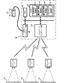
図1に示す画像表示システムは、画像表示制御装置であるパーソナルコンピュータ(以下、単にPCと略す)100と、画像表示装置である3台のプロジェクタA〜Cと、で構成されている。 The image display system shown in FIG. 1 includes a personal computer (hereinafter simply referred to as a PC) 100 that is an image display control device and three projectors A to C that are image display devices.
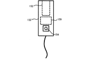
このうち、PC100は、図1に示すように、プログラムを実行することにより種々の処理や制御を行うCPU110と、プログラムを格納したり、データや情報を格納したりするためのメモリ120と、無線LANを介してプロジェクタA〜Cとの間で各種データや情報などの伝送を行うネットワークインタフェース部130と、リモートコントローラ(以下、単にリモコンと略す)150との間で各種データや情報などの伝送を行うリモコンインタフェース部140と、を備えており、それらはバス等を介して接続されている。また、PC100の外部には、リモコン150が存在し、ケーブルを介して、リモコンインタフェース部140に接続されている。リモコン150は、画像を撮像するためのカメラ152を内蔵しており、外面には、外部からの指示をPC100に伝えるための操作ボタン154が設けられている。また、メモリ120は、取得情報格納部122,確定第1情報格納部124,確定第2情報格納部126,及びコンテンツ格納部128として機能する。また、PC100は、上記構成要素以外にも、キーボードやポインティングデバイスなどの入力部やモニタなどの表示部やスピーカなどの音声出力部などを備えているが、図では省略されている。
Among these, as shown in FIG. 1, the
一方、3台のプロジェクタA〜Cは、図1に示すように、並列に配置されており、各スクリーンSA〜SCに対して、それぞれ、画像を投射表示することが可能となっている。なお、各プロジェクタA〜Cの構成は、互いに同じであり、図2に示すような構成を成している。図2は図1におけるプロジェクタの構成を示すブロック図である。図2では、プロジェクタA〜Cを、プロジェクタ200として示している。
On the other hand, as shown in FIG. 1, the three projectors A to C are arranged in parallel and can project and display images on the screens SA to SC, respectively. The projectors A to C have the same configuration as shown in FIG. FIG. 2 is a block diagram showing the configuration of the projector in FIG. In FIG. 2, projectors A to C are shown as
図2に示すように、プロジェクタ200は、プログラムを実行することにより種々の処理や制御を行うCPU210と、プログラムを格納したり、データや情報を格納したりするためのメモリ220と、無線LANを介してPC100との間で各種データや情報などの伝送を行うネットワークインタフェース部230と、画像処理回路242と、画像重畳回路244と、画像切換回路246と、液晶パネル駆動回路248と、を備えており、それらはバス等を介して接続されている。また、その他、照明光学系250と、液晶パネル260と、投射光学系270と、を備えている。また、メモリ220は、コンテンツ用2次元コード格納部222及び待ち受け画像格納部224として機能する。
As shown in FIG. 2, the
A−2.実施例の動作:
A−2−1.初期動作:
各プロジェクタA〜Cでは、電源を投入すると、CPU210が、メモリ220に格納されたファームウェア(図示せず)を実行し、それに従い、他の各構成要素を制御する。まず、待ち受け画像格納部224から、待ち受け画像データが読み出され、画像切換回路246を介して、液晶パネル駆動回路248に入力される。液晶パネル駆動回路248は、入力された待ち受け画像データに基づいて、液晶パネル260に待ち受け画像を表示する。液晶パネル260は、照明光学系250でほぼ均一に照明されており、液晶パネル260に表示された待ち受け画像は、投射光学系270によってスクリーンS上に投射表示される。
こうして、各プロジェクタA〜Cは、電源投入後の初期状態では、各スクリーンSA〜SCに、それぞれ、待ち受け画像を投射表示する。
A-2. Example operation:
A-2-1. Initial operation:
In each of the projectors A to C, when the power is turned on, the
Thus, the projectors A to C project and display the standby images on the screens SA to SC in the initial state after the power is turned on.
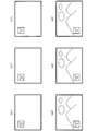
図3は図1の各プロジェクタA〜Cによって投射表示された画像の一例を示す説明図である。上記した初期状態で、各プロジェクタA〜Cによって投射表示される待ち受け画像は、例えば、図3(a1),(b1),(c1)に示す如くである。各待ち受け画像には、各プロジェクタA〜Cに対応する待ち受け用2次元コードma,mb,mcが、それぞれ含まれている。すなわち、各プロジェクタA〜C毎に、予め、待ち受け画像格納部224に格納されている待ち受け画像データには、それぞれ、対応する待ち受け用2次元コードが挿入されている。また、各プロジェクタA〜Cに対応する待ち受け用2次元コードma,mb,mcは、それぞれ、待ち受け用であることを示す識別情報や、対応するプロジェクタの識別情報や、対応するプロジェクタとの間でネットワーク接続を確立するために必要な接続情報などを、統合的にコード化して、生成されたものである。なお、図3において、(a2),(b2),(c2)の各画像については、後ほど説明する。また、本実施例では、コード化された情報として、2次元コードを用いる場合について説明するが、コード化された情報としては、コンテンツの内容等が判別できれば、その他の情報、例えば、暗号化された情報であっても構わない。
FIG. 3 is an explanatory diagram showing an example of an image projected and displayed by the projectors A to C in FIG. The standby images projected and displayed by the projectors A to C in the above-described initial state are, for example, as shown in FIGS. 3 (a1), (b1), and (c1). Each standby image includes standby two-dimensional codes ma, mb, and mc corresponding to the projectors A to C, respectively. That is, for each projector A to C, the corresponding standby two-dimensional code is inserted into the standby image data stored in the standby
一方、図1において、PC100の電源を入れ、CPU110によって、メモリ120に格納された専用のアプリケーションプログラム(図示せず)を起動すると、リモコン150等の利用が可能となる。それにより、リモコン150では、カメラ152が撮像を開始する。撮像された撮像画像データは、ケーブルを介して、PC100内のリモコンインタフェース部140に取り込まれる。CPU110は、取り込まれた撮像画像データに、2次元コードが含まれているかどうかをチェックする。
On the other hand, in FIG. 1, when the
A−2−2.コンテンツ画像への切り換え動作:
図4及び図5は第1の実施例における待ち受け画像からコンテンツ画像への切り換え動作を説明するための説明図である。
A-2-2. Switching to content image:
4 and 5 are explanatory diagrams for explaining the switching operation from the standby image to the content image in the first embodiment.
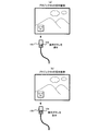
そこで、ユーザが、リモコン150を手で持ち、各プロジェクタA〜Cによってそれぞれ表示されている3つの待ち受け画像のうち、図4(a)に示すように、プロジェクタAによる待ち受け画像の方に、リモコン150の先端を向けると、リモコン150に内蔵されたカメラ152は、プロジェクタAによる待ち受け画像を撮像する。その待ち受け画像には、プロジェクタAに対応する待ち受け用2次元コードmaが含まれているため、上記チェックを行っているCPU110は、取り込まれた撮像画像データ内で、その待ち受け用2次元コードmaを検出する。そして、CPU110は、その待ち受け用2次元コードmaを解析して、そのコードmaの表す情報を取得し、取得情報格納部122に格納すると共に、音声出力部(図示せず)から、2次元コードの情報を取得したことを示す確認音を発生させる。
Therefore, the user holds the
その確認音を聞いた後、ユーザが、図4(a)に示すように、プロジェクタAによる待ち受け画像の方に、リモコン150の先端を向けたまま、リモコン150の操作ボタン154を押すと、その操作に基づき、リモコン150からは、ケーブルを介して、第1の指示信号が出力される。その第1の指示信号は、リモコンインタフェース部140を介して、CPU110に伝えられる。CPU110が、その第1の指示信号を受け取ると、そのタイミングで、取得情報格納部122に格納した取得情報を読み出し、確定第1情報格納部124に格納して、取得情報の確定を行う。このとき確定された取得情報、すなわち、確定第1情報格納部124に格納された取得情報を、確定第1情報とする。
After listening to the confirmation sound, as shown in FIG. 4A, when the user presses the
その後、ユーザが、図4(b)に示すように、プロジェクタAによる待ち受け画像の方に、リモコン150の先端を向けたまま、押していた操作ボタン154を放すと、その操作に基づき、リモコン150からは、ケーブルを介して、第2の指示信号が出力される。その第2の指示信号も、リモコンインタフェース部140を介して、CPU110に伝えられる。CPU110が、その第2の指示信号を受け取ると、前回と同様に、そのタイミングで、取得情報格納部122に格納した取得情報を読み出し、今度は、確定第2情報格納部126に格納して、取得情報の確定を行う。このとき確定された取得情報、すなわち、確定第2情報格納部126に格納された取得情報を、確定第2情報とする。
Thereafter, as shown in FIG. 4B, when the user releases the
そして、CPU110は、確定第1情報格納部124に格納した確定第1情報と、確定第2情報格納部126に格納した確定第2情報と、をそれぞれ読み出し、両者を比較する。これらの情報は同じ情報であるので、CPU110は、比較結果として、確定第1情報と確定第2情報とは互いに一致すると判定する。このような判定が出た場合、CPU110は、確定第1情報または確定第2情報から識別情報を抽出して、その識別情報から、プロジェクタAが待ち受け画像表示状態にあることを認識すると、そのプロジェクタAとの間でネットワーク接続の確立を行うべく、確定第1情報または確定第2情報から、さらに、ネットワーク接続の確立に必要な接続情報を抽出する。そして、CPU110は、ネットワークインタフェース部130を制御して、抽出した接続情報に基づき、無線LANを介して、プロジェクタAとの間でネットワーク接続の確立を実行する。その後、プロジェクタAとの間でネットワーク接続が確立したら、コンテンツ格納部128に格納されているコンテンツデータに基づき、コンテンツ画像データを無線LANを介してプロジェクタAに伝送する。
Then, the
一方、プロジェクタAにおいて、図2に示すコンテンツ用2次元コード格納部222には、プロジェクタAに対応するコンテンツ用2次元コードnaが格納されている。プロジェクタAに対応するコンテンツ用2次元コードnaは、コンテンツ用であることを示す識別情報や、対応するプロジェクタAの識別情報報などを、統合的にコード化して、生成されたものである。そこで、プロジェクタAにおいて、CPU210が、ネットワークインタフェース部230を介して、PC100との間でネットワーク接続が確立されたことを検出すると、PC100から伝送されたコンテンツ画像データを、ネットワークインタフェース部230を介して受信する。画像処理回路242は、その受信したコンテンツ画像データに所望の画像処理を施して、画像重畳回路244に出力する。画像重畳回路244は、コンテンツ用2次元コード格納部222から、コンテンツ用2次元コードnaを読み出して、入力されたコンテンツ画像データに、そのコンテンツ用2次元コードnaを挿入し、挿入後のコンテンツ画像データを出力する。
On the other hand, in the projector A, the content two-dimensional code na corresponding to the projector A is stored in the content two-dimensional
また、CPU210は、PC100との間でネットワーク接続が確立されたことを受けて、画像切換回路246を制御して、待ち受け画像格納部224から読み出された待ち受け画像データに代えて、画像重畳回路244から出力されるコンテンツ画像データを、液晶パネル駆動回路248に出力させる。液晶パネル駆動回路248は、入力されたコンテンツ画像データに基づいて、液晶パネル260にコンテンツ画像を表示する。この結果、プロジェクタAは、図5または図3(a2)に示すように、スクリーンSAに、待ち受け画像に代えて、PC100から伝送されたコンテンツ画像を投射表示する。そして、そのコンテンツ画像には、画像重畳回路244によって挿入されたコンテンツ用2次元コードnaが含まれることになる。
In response to the establishment of the network connection with the
以上のようにして、ユーザが、リモコン150の先端を、プロジェクタAによる待ち受け画像に向けた状態で、リモコン150の操作ボタン154を押して、放す操作を行うだけで、待ち受け画像を投射表示していたプロジェクタAに、待ち受け画像に代えて、PC100からのコンテンツ画像を投射表示させるようすることができる。
As described above, the user has projected and displayed the standby image only by pressing and releasing the
なお、上記の説明では、プロジェクタAを対象としたが、他のプロジェクタB,Cに関しても、同様の動作を実現することが可能である。その結果として、対応するスクリーンSB,SCには、それぞれ、待ち受け画像に代えて、図3(b2),(c2)に示すようなPC100から伝送されたコンテンツ画像が投射表示される。なお、それらコンテンツ画像には、プロジェクタB,Cに対応するコンテンツ用2次元コードnb,cが、それぞれ含まれている。
In the above description, the projector A is targeted, but the same operation can be realized for the other projectors B and C. As a result, content images transmitted from the
A−2−3.待ち受け画像への切り換え動作:
図6及び図7は第1の実施例におけるコンテンツ画像から待ち受け画像への切り換え動作を説明するための説明図である。
A-2-3. Switching to the standby image:
6 and 7 are explanatory diagrams for explaining the switching operation from the content image to the standby image in the first embodiment.
次に、ユーザが、リモコン150を手で持ち、図6(a)に示すように、プロジェクタAによるコンテンツ画像の方に、リモコン150の先端を向けると、リモコン150に内蔵されたカメラ152は、プロジェクタAによるコンテンツ画像を撮像する。そのコンテンツ画像には、上述したとおり、プロジェクタAに対応するコンテンツ用2次元コードnaが含まれているため、CPU110は、取り込まれた撮像画像データ内で、そのコンテンツ用2次元コードnaを検出する。そして、CPU110は、そのコンテンツ用2次元コードnaを解析して、そのコードnaの表す情報を取得し、取得情報格納部122に格納すると共に、音声出力部(図示せず)から、2次元コードの情報を取得したことを示す確認音を発生させる。
Next, when the user holds the
その確認音を聞いた後、ユーザが、図6(a)に示すように、プロジェクタAによるコンテンツ画像の方に、リモコン150の先端を向けたまま、リモコン150の操作ボタン154を押すと、その操作に基づき、リモコン150からは第1の指示信号が出力される。その第1の指示信号は、リモコンインタフェース部140を介して、CPU110に伝えられる。CPU110が、その第1の指示信号を受け取ると、そのタイミングで、取得情報格納部122に格納した取得情報を読み出し、確定第1情報格納部124に格納して、取得情報の確定を行い、確定第1情報とする。
After hearing the confirmation sound, as shown in FIG. 6A, when the user presses the
その後、ユーザが、図6(b)に示すように、プロジェクタAによるコンテンツ画像の方に、リモコン150の先端を向けたまま、押していた操作ボタン154を放すと、その操作に基づき、リモコン150からは第2の指示信号が出力される。その第2の指示信号も、リモコンインタフェース部140を介して、CPU110に伝えられる。CPU110が、その第2の指示信号を受け取ると、そのタイミングで、取得情報格納部122に格納した取得情報を読み出し、確定第2情報格納部126に格納して、取得情報の確定を行い、確定第2情報とする。
Thereafter, as shown in FIG. 6B, when the user releases the pressed
そして、CPU110は、確定第1情報格納部124に格納した確定第1情報と、確定第2情報格納部126に格納した確定第2情報と、をそれぞれ読み出し、両者を比較する。これらの情報は同じ情報であるので、CPU110は、比較結果として、確定第1情報と確定第2情報とは互いに一致すると判定する。このような判定が出た場合、CPU110は、確定第1情報または確定第2情報から識別情報を抽出して、その識別情報から、プロジェクタAがコンテンツ画像表示状態にあることを認識すると、ネットワークインタフェース部130を制御して、そのプロジェクタAとの間でのネットワーク接続を切断する。
Then, the
一方、プロジェクタAにおいて、CPU210が、ネットワークインタフェース部230を介して、PC100との間でのネットワーク接続が切断されたことを検出すると、画像切換回路246を制御して、画像重畳回路244からのデータに代えて、待ち受け画像格納部224から読み出される待ち受け画像データを、液晶パネル駆動回路248に出力する。液晶パネル駆動回路248は、入力された待ち受け画像データに基づいて、液晶パネル260に待ち受け画像を表示する。この結果、プロジェクタAは、図7または図3(a1)に示すように、スクリーンSAに、PC100からのコンテンツ画像に代えて、待ち受け画像を投射表示する。
On the other hand, in the projector A, when the
以上のようにして、ユーザが、リモコン150の先端を、プロジェクタAによるコンテンツ画像に向けた状態で、リモコン150の操作ボタン154を押して、放す操作を行うだけで、PC100からのコンテンツ画像を投射表示していたプロジェクタAに、そのコンテンツ画像に代えて、待ち受け画像を投射表示させるようすることができる。
なお、上記の説明では、プロジェクタAを対象としたが、他のプロジェクタB,Cに関しても、同様の動作を実現することが可能である。
As described above, the user can project and display the content image from the
In the above description, the projector A is targeted, but the same operation can be realized for the other projectors B and C.
A−2−4.コンテンツ画像の移し換え動作:
図8及び図9は第1の実施例におけるプロジェクタ間でのコンテンツ画像の移し換え動作を説明するための説明図である。
A-2-4. Content image transfer operation:
8 and 9 are explanatory diagrams for explaining the operation of transferring content images between projectors in the first embodiment.
今、図8(a)に示すように、プロジェクタAがコンテンツ画像を投射表示し、プロジェクタBが待ち受け画像を投射表示しているものとする。そのような表示状態において、まず、ユーザが、リモコン150を手で持ち、プロジェクタAによるコンテンツ画像の方に、リモコン150の先端を向けると、リモコン150に内蔵されたカメラ152は、プロジェクタAによるコンテンツ画像を撮像する。そのコンテンツ画像には、プロジェクタAに対応するコンテンツ用2次元コードnaが含まれているため、CPU110は、取り込まれた撮像画像データ内で、そのコンテンツ用2次元コードnaを検出する。そして、CPU110は、そのコンテンツ用2次元コードnaを解析して、そのコードnaの表す情報を取得し、取得情報格納部122に格納すると共に、音声出力部(図示せず)から、2次元コードの情報を取得したことを示す確認音を発生させる。
Now, as shown in FIG. 8A, it is assumed that projector A projects and displays a content image, and projector B projects and displays a standby image. In such a display state, when the user first holds the
その確認音を聞いた後、ユーザが、図8(a)に示すように、プロジェクタAによるコンテンツ画像の方に、リモコン150の先端を向けたまま、リモコン150の操作ボタン154を押すと、その操作に基づき、リモコン150からは第1の指示信号が出力される。その第1の指示信号は、リモコンインタフェース部140を介して、CPU110に伝えられる。CPU110が、その第1の指示信号を受け取ると、そのタイミングで、取得情報格納部122に格納した取得情報を読み出し、確定第1情報格納部124に格納して、取得情報の確定を行い、確定第1情報とする。
After hearing the confirmation sound, as shown in FIG. 8A, when the user presses the
その後、ユーザが、リモコン150の操作ボタン154を押したままで、図8(b)に示すように、リモコン150の向きを変え、プロジェクタBによる待ち受け画像の方に、リモコン150の先端を向けると、リモコン150に内蔵されたカメラ152は、今度は、プロジェクタBによる待ち受け画像を撮像する。その待ち受け画像には、プロジェクタBに対応する待ち受け用2次元コードmbが含まれているため、CPU110は、取り込まれた撮像画像データ内で、その待ち受け用2次元コードmbを検出する。そして、CPU110は、その待ち受け用2次元コードmbを解析して、そのコードmbの表す情報を取得し、取得情報格納部122に格納すると共に、音声出力部(図示せず)から、2次元コードの情報を取得したことを示す確認音を発生させる。
After that, when the user presses the
その確認音を聞いた後、ユーザが、図8(b)に示すように、プロジェクタBによる待ち受け画像の方に、リモコン150の先端を向けたまま、リモコン150の操作ボタン154を放すと、その操作に基づき、リモコン150からは第2の指示信号が出力される。その第2の指示信号も、リモコンインタフェース部140を介して、CPU110に伝えられる。CPU110が、その第2の指示信号を受け取ると、そのタイミングで、取得情報格納部122に格納した取得情報を読み出し、確定第2情報格納部126に格納して、取得情報の確定を行い、確定第2情報とする。
After hearing the confirmation sound, as shown in FIG. 8B, when the user releases the
そして、CPU110は、確定第1情報格納部124に格納した確定第1情報と、確定第2情報格納部126に格納した確定第2情報と、をそれぞれ読み出し、両者を比較する。これらの情報は異なる情報であるので、CPU110は、比較結果として、確定第1情報と確定第2情報とは互いに異なると判定する。このような判定が出た場合、CPU110は、まず、確定第1情報から識別情報を抽出して、その識別情報から、プロジェクタAがコンテンツ画像表示状態にあることを認識すると、ネットワークインタフェース部130を制御して、そのプロジェクタAとの間でのネットワーク接続を切断する。次に、CPU110は、確定第2情報から識別情報を抽出して、その識別情報から、プロジェクタBが待ち受け画像表示状態にあることを認識すると、そのプロジェクタBとの間でネットワーク接続の確立を行うべく、確定第2情報から、さらに、ネットワーク接続の確立に必要な接続情報を抽出する。そして、CPU110は、ネットワークインタフェース部130を制御して、抽出した接続情報に基づき、無線LANを介して、プロジェクタBとの間でネットワーク接続の確立を実行する。その後、プロジェクタBとの間でネットワーク接続が確立したら、コンテンツ格納部128に格納されているコンテンツデータに基づき、コンテンツ画像データを無線LANを介してプロジェクタBに伝送する。
Then, the
一方、プロジェクタAにおいて、CPU210が、ネットワークインタフェース部230を介して、PC100との間でのネットワーク接続が切断されたことを検出すると、画像切換回路246を制御して、画像重畳回路244からのデータに代えて、待ち受け画像格納部224から読み出される待ち受け画像データを、液晶パネル駆動回路248に出力する。液晶パネル駆動回路248は、入力された待ち受け画像データに基づいて、液晶パネル260に待ち受け画像を表示する。
On the other hand, in the projector A, when the
他方、プロジェクタBにおいては、CPU210が、ネットワークインタフェース部230を介して、PC100との間でネットワーク接続が確立されたことを検出すると、PC100から伝送されたコンテンツ画像データを、ネットワークインタフェース部230を介して受信する。画像処理回路242は、その受信したコンテンツ画像データに所望の画像処理を施し、画像重畳回路244は、コンテンツ用2次元コード格納部222から、プロジェクタBに対応するコンテンツ用2次元コードnbを読み出し、画像処理回路242からのコンテンツ画像データに、そのコンテンツ用2次元コードnbを挿入し、挿入後のコンテンツ画像データを出力する。そして、CPU210は、PC100との間でネットワーク接続が確立されたことを受けて、画像切換回路246を制御して、待ち受け画像格納部224から読み出された待ち受け画像データに代えて、画像重畳回路244から出力されるコンテンツ画像データを、液晶パネル駆動回路248に出力させる。液晶パネル駆動回路248は、入力されたコンテンツ画像データに基づいて、液晶パネル260にコンテンツ画像を表示する。
On the other hand, in the projector B, when the
以上の結果、図9に示すように、プロジェクタAは、スクリーンSAに、PC100からのコンテンツ画像に代えて、待ち受け画像を投射表示するのに対し、プロジェクタBは、スクリーンSBに、待ち受け画像に代えて、PC100から伝送されたコンテンツ画像を投射表示する。
As a result, as shown in FIG. 9, the projector A projects and displays a standby image on the screen SA instead of the content image from the
以上のようにして、ユーザが、リモコン150の先端を、まず、プロジェクタAによるコンテンツ画像に向けた状態で、リモコン150の操作ボタン154を押し、その操作ボタン154を押したままの状態で、リモコン150の向きを変え、リモコン150の先端を、今度は、プロジェクタBによる待ち受け画像に向けた状態で、操作ボタン154を放す操作を行うと、プロジェクタAによってスクリーンSAに投射表示されていたPC100からのコンテンツ画像が、今度は、プロジェクタBによってスクリーンSBに投射表示されることになり、あたかも、投射画像であるコンテンツ画像が、スクリーンSAからスクリーンSBに移動したように見せることができる。
As described above, the user first presses the
なお、上記の説明では、プロジェクタAからプロジェクタBへの移し換えについて説明したが、逆向きのプロジェクタBからプロジェクタAへの移し換えについても、同じようにして実現することができる。また、プロジェクタA,B間だけでなく、プロジェクタA,C間や、プロジェクタB,C間においても、同様の動作を実現することが可能である。 In the above description, the transfer from the projector A to the projector B has been described. However, the reverse transfer from the projector B to the projector A can be similarly realized. Further, the same operation can be realized not only between the projectors A and B but also between the projectors A and C and between the projectors B and C.
A−3.実施例の効果:
以上説明したとおり、本実施例によれば、ユーザは、リモコン150の先端を投射画像の方に向け、リモコン150の操作ボタン154を押して放すだけの、より少ない簡単な操作にて、画像の切り換えや、画像の移し換えなど、プロジェクタによる投射画像の表示の仕方を変えることができる。
A-3. Effects of the embodiment:
As described above, according to the present embodiment, the user can switch images with fewer simple operations by simply pointing the front end of the
B.第2の実施例:
上記した第1の実施例では、ユーザが、投射画像の方にリモコン150の先端を向けたままの状態で、リモコン150の操作ボタン154を押して放す操作を行うことにより、待ち受け画像への切り換えや、コンテンツ画像への切り換えを行うようにしていた。しかしながら、ユーザの後述するような操作で、待ち受け画像への切り換えや、コンテンツ画像への切り換えを行うようにしてもよい。
B. Second embodiment:
In the first embodiment described above, when the user performs an operation of pressing and releasing the
そのような実施例を第2の実施例として説明する。なお、本実施例の構成は、第1の実施例の場合と同様であるので、それらについての説明は省略する。なお、本実施例では、取得情報格納部122は、構成要素として、必ずしも必要でない。
Such an embodiment will be described as a second embodiment. Note that the configuration of this embodiment is the same as that of the first embodiment, and a description thereof will be omitted. In the present embodiment, the acquisition
B−1.実施例の動作:
B−1−1.コンテンツ画像への切り換え動作:
図10は本発明の第2の実施例における待ち受け画像からコンテンツ画像への切り換え動作を説明するための説明図である。
B-1. Example operation:
B-1-1. Switching to content image:
FIG. 10 is an explanatory diagram for explaining the switching operation from the standby image to the content image in the second embodiment of the present invention.
ユーザが、リモコン150を手で持ち、図10(a)に示すように、投射画像のない方に、リモコン150の先端を向けると、リモコン150に内蔵されたカメラ152は、その向けた方の背景を撮像する。撮像された撮像画像データは、ケーブルを介して、PC100内のリモコンインタフェース部140に取り込まれる。そして、ユーザが、図10(a)に示すように、投射画像のない方に、リモコン150の先端を向けたまま、リモコン150の操作ボタン154を押すと、その操作に基づき、リモコン150からは、ケーブルを介して、第1の指示信号が出力される。その第1の指示信号は、リモコンインタフェース部140を介して、CPU110に伝えられる。CPU110が、その第1の指示信号を受け取ると、そのタイミングで、取り込まれた撮像画像データに、2次元コードが含まれているかどうかをチェックする。このとき、撮像画像には何ら2次元コードが含まれていないため、CPU110は、取り込まれた撮像画像データ内で、2次元コードも何も検出しない。従って、CPU110は、確定第1情報格納部124に何ら情報を格納することなく、取得情報の確定を行う。よって、このとき、確定第1情報格納部124内の不定の情報が、確定第1情報となる。
When the user holds the
その後、ユーザが、リモコン150の操作ボタン154を押したままで、図10(b)に示すように、リモコン150の向きを変え、プロジェクタAによる待ち受け画像の方に、リモコン150の先端を向けると、リモコン150に内蔵されたカメラ152は、今度は、プロジェクタAによる待ち受け画像を撮像し、撮像された撮像画像データはリモコンインタフェース部140に取り込まれる。そして、ユーザが、図10(b)に示すように、プロジェクタAによる待ち受け画像の方に、リモコン150の先端を向けたまま、リモコン150の操作ボタン154を放すと、その操作に基づき、リモコン150からは第2の指示信号が出力される。その第2の指示信号も、リモコンインタフェース部140を介して、CPU110に伝えられる。CPU110が、その第2の指示信号を受け取ると、そのタイミングで、取り込まれた撮像画像データに、2次元コードが含まれているかどうかをチェックする。このとき、撮像画像には、プロジェクタAに対応する待ち受け用2次元コードmaが含まれているため、CPU110は、取り込まれた撮像画像データ内で、その待ち受け用2次元コードmaを検出する。そして、CPU110は、その待ち受け用2次元コードmaを解析して、そのコードmaの表す情報を取得し、確定第2情報格納部126に格納して、取得情報の確定を行う。このとき確定された取得情報、すなわち、確定第2情報格納部126に格納された取得情報を、確定第2情報とする。
After that, when the user presses the
そして、CPU110は、確定第1情報格納部124に格納した確定第1情報と、確定第2情報格納部126に格納した確定第2情報と、をそれぞれ読み出し、両者を比較する。これらの情報は異なる情報であるので、CPU110は、比較結果として、確定第1情報と確定第2情報とは互いに異なると判定する。このような判定が出た場合、CPU110は、確定第1情報が不定の情報であり、確定第2情報が不定の情報でない(取得情報が存在する)ことから、最初にリモコン150が向けられた方向に投射画像がなく、次にリモコン150が向けられた方向に投射画像があることを認識する。そして、CPU110は、さらに、確定第2情報から識別情報を抽出して、その識別情報から、プロジェクタAが待ち受け画像表示状態にあることを認識すると、そのプロジェクタAとの間でネットワーク接続の確立を行うべく、確定第2情報から接続情報を抽出する。そして、CPU110は、ネットワークインタフェース部130を制御して、抽出した接続情報に基づき、無線LANを介して、プロジェクタAとの間でネットワーク接続の確立を行う。その後、プロジェクタAとの間でネットワーク接続が確立したら、コンテンツ格納部128に格納されているコンテンツデータに基づき、コンテンツ画像データを無線LANを介してプロジェクタAに伝送する。その後、CPU110は、確定第1情報格納部124,確定第2情報格納部126内の情報を削除する。
なお、プロジェクタA側の動作は、第1の実施例の場合と同様であるので説明は省略する。
Then, the
Since the operation on the projector A side is the same as that in the first embodiment, description thereof is omitted.
以上のようにして、ユーザが、リモコン150の先端を、まず、投射画像のない方に向けた状態で、リモコン150の操作ボタン154を押し、その操作ボタン154を押したままの状態で、リモコン150の向きを変え、リモコン150の先端を、今度は、プロジェクタAによる待ち受け画像の方に向けた状態で、操作ボタン154を放す操作を行うと、待ち受け画像を投射表示していたプロジェクタAに、待ち受け画像に代えて、図5に示したように、PC100からのコンテンツ画像を投射表示させるようすることができる。
なお、上記の説明では、プロジェクタAを対象としたが、他のプロジェクタB,Cに関しても、同様の動作を実現することが可能である。
As described above, the user first presses the
In the above description, the projector A is targeted, but the same operation can be realized for the other projectors B and C.
B−1−2.待ち受け画像への切り換え動作:
図11は第2の実施例におけるコンテンツ画像から待ち受け画像への切り換え動作を説明するための説明図である。
B-1-2. Switching to the standby image:
FIG. 11 is an explanatory diagram for explaining the switching operation from the content image to the standby image in the second embodiment.
ユーザが、リモコン150を手で持ち、図11(a)に示すように、プロジェクタAによるコンテンツ画像の方に、リモコン150の先端を向けると、リモコン150に内蔵されたカメラ152は、プロジェクタAによるコンテンツ画像を撮像する。そして、ユーザが、図11(a)に示すように、プロジェクタAによるコンテンツ画像の方に、リモコン150の先端を向けたまま、リモコン150の操作ボタン154を押すと、その操作に基づき、リモコン150からは第1の指示信号が出力され、リモコンインタフェース部140を介して、CPU110に伝えられる。CPU110が、その第1の指示信号を受け取ると、そのタイミングで、取り込まれた撮像画像データに、2次元コードが含まれているかどうかをチェックする。このとき、撮像画像には、プロジェクタAに対応するコンテンツ用2次元コードnaが含まれているため、CPU110は、取り込まれた撮像画像データ内で、そのコンテンツ用2次元コードnaを検出する。そして、CPU110は、そコンテンツ用2次元コードnaを解析して、そのコードnaの表す情報を取得し、確定第1情報格納部124に格納して、取得情報の確定を行う。このとき確定された取得情報、すなわち、確定第1情報格納部124に格納された取得情報を、確定第1情報とする。
When the user holds the
その後、ユーザが、リモコン150の操作ボタン154を押したままで、図11(b)に示すように、リモコン150の向きを変え、投射画像のない方に、リモコン150の先端を向けると、リモコン150に内蔵されたカメラ152は、今度は、その向けた方の背景を撮像し、撮像された撮像画像データはリモコンインタフェース部140に取り込まれる。そして、ユーザが、図11(b)に示すように、投射画像のない方に、リモコン150の先端を向けたまま、リモコン150の操作ボタン154を放すと、その操作に基づき、リモコン150からは第2の指示信号が出力され、リモコンインタフェース部140を介して、CPU110に伝えられる。CPU110が、その第2の指示信号を受け取ると、そのタイミングで、取り込まれた撮像画像データに、2次元コードが含まれているかどうかをチェックする。このとき、撮像画像には何ら2次元コードが含まれていないため、CPU110は、取り込まれた撮像画像データ内で、2次元コードも何も検出しない。従って、CPU110は、確定第2情報格納部126に何ら情報を格納することなく、取得情報の確定を行う。よって、このとき、確定第2情報格納部126内の不定の情報が、確定第2情報となる。
After that, when the user presses the
そして、CPU110は、確定第1情報格納部124に格納した確定第1情報と、確定第2情報格納部126に格納した確定第2情報と、をそれぞれ読み出し、両者を比較する。これらの情報は異なる情報であるので、CPU110は、比較結果として、確定第1情報と確定第2情報とは互いに異なると判定する。このような判定が出た場合、CPU110は、確定第1情報が不定の情報でなく(取得情報が存在する)、確定第2情報が不定の情報であることから、最初にリモコン150が向けられた方向に投射画像があり、次にリモコン150が向けられた方向に投射画像がないことを認識する。そして、CPU110は、さらに、確定第1情報から識別情報を抽出して、その識別情報から、プロジェクタAがコンテンツ画像表示状態にあることを認識すると、ネットワークインタフェース部130を制御して、そのプロジェクタAとの間でのネットワーク接続を切断する。その後、CPU110は、確定第1情報格納部124,確定第2情報格納部126内の情報を削除する。
なお、プロジェクタA側の動作は、第1の実施例の場合と同様であるので説明は省略する。
Then, the
Since the operation on the projector A side is the same as that in the first embodiment, description thereof is omitted.
以上のようにして、ユーザが、リモコン150の先端を、まず、プロジェクタAによるコンテンツ画像の方に向けた状態で、リモコン150の操作ボタン154を押し、その操作ボタン154を押したままの状態で、リモコン150の向きを変え、リモコン150の先端を、今度は、投射画像も何もないに方に向けた状態で、操作ボタン154を放す操作を行うと、コンテンツ画像を投射表示していたプロジェクタAに、そのコンテンツ画像に代えて、図7に示したように、待ち受け画像を投射表示させるようすることができる。
なお、上記の説明では、プロジェクタAを対象としたが、他のプロジェクタB,Cに関しても、同様の動作を実現することが可能である。
As described above, the user first presses the
In the above description, the projector A is targeted, but the same operation can be realized for the other projectors B and C.
B−2.実施例の効果:
以上説明したとおり、本実施例においても、ユーザは、リモコン150の先端を、投射画像のない方やある方に向け、リモコン150の操作ボタン154を押して放すだけの、より少ない簡単な操作にて、画像の切り換えや、画像の移し換えなど、プロジェクタによる投射画像の表示の仕方を変えることができる。
B-2. Effects of the embodiment:
As described above, also in the present embodiment, the user can point the tip of the
C.第3の実施例:
上記した第1の実施例では、ユーザが、リモコン150の先端を或るプロジェクタによるコンテンツ画像に向けて、リモコン150の操作ボタン154を押し、その後、リモコン150の先端を他のプロジェクタによる待ち受け画像に向けて、操作ボタン154を放す操作を行うことにより、あたかも、投射画像であるコンテンツ画像が、或るスクリーンから他のスクリーンに移動したように見せるようにしていた。しかし、同じような操作によって、投射画像であるコンテンツ画像を、或るスクリーンから他のスクリーンに複写したように見せるようにすることもできる。
C. Third embodiment:
In the first embodiment described above, the user presses the
そのような実施例を第3の実施例として説明する。なお、本実施例の構成は、第1の実施例の場合とほぼ同様であるが、リモコンに、操作ボタン154の他に、上記した画像複写用の操作ボタン156を新たに設けた点が異なる。
Such an embodiment will be described as a third embodiment. The configuration of the present embodiment is almost the same as that of the first embodiment, except that the
C−1.実施例の動作:
C−1−1.コンテンツ画像の移し換え動作:
図12及び図13は本発明の第3の実施例におけるプロジェクタ間でコンテンツ画像の複写動作を説明するための説明図である。
C-1. Example operation:
C-1-1. Content image transfer operation:
FIGS. 12 and 13 are explanatory diagrams for explaining the copying operation of the content image between the projectors in the third embodiment of the present invention.
ユーザが、リモコン150’を用いて行う操作は、リモコン150’の操作ボタンとして、操作ボタン154の代わりに、画像複写用操作ボタン156を用いる以外は、第1の実施例におけるコンテンツ画像の移し換え動作の場合と同様である。すなわち、ユーザが、リモコン150’の先端を、まず、プロジェクタAによるコンテンツ画像に向けた状態で、リモコン150’の画像複写用操作ボタン156を押し、その操作ボタン156を押したままの状態で、リモコン150’の向きを変え、リモコン150’の先端を、今度は、プロジェクタBによる待ち受け画像に向けた状態で、画像複写用操作ボタン156を放す操作を行うのである。
The operation performed by the user using the
また、このときのPC100の動作も、確定第1情報及び確定第2情報が確定するまでの動作は、第1の実施例におけるコンテンツ画像の移し換え動作の場合とほぼ同様であるため、その後の動作について、以下説明する。
Also, the operation of the
PC100において、CPU110は、確定第1情報格納部124に格納した確定第1情報(すなわち、プロジェクタAに対応するコンテンツ用2次元コードnaの表す情報)と、確定第2情報格納部126に格納した確定第2情報(すなわち、プロジェクタBに対応する待ち受け用2次元コードmbの表す情報)と、をそれぞれ読み出し、両者を比較する。これらの情報は異なる情報であるので、CPU110は、比較結果として、確定第1情報と確定第2情報とは互いに異なると判定する。このような判定が出た場合、CPU110は、まず、確定第1情報から識別情報を抽出して、その識別情報から、プロジェクタAがコンテンツ画像表示状態にあることを認識すると、プロジェクタAに対して新たな動作を行うことなく、現状のコンテンツ画像表示状態を維持させる。次に、CPU110は、確定第2情報から識別情報を抽出して、その識別情報から、プロジェクタBが待ち受け画像表示状態にあることを認識すると、そのプロジェクタBとの間でネットワーク接続の確立を行うべく、確定第2情報から、さらに、ネットワーク接続の確立に必要な接続情報を抽出する。そして、CPU110は、ネットワークインタフェース部130を制御して、抽出した接続情報に基づき、無線LANを介して、プロジェクタBとの間でネットワーク接続の確立を実行する。その後、プロジェクタBとの間でネットワーク接続が確立したら、コンテンツ格納部128に格納されているコンテンツデータに基づき、コンテンツ画像データを無線LANを介して、プロジェクタAの他に、さらにプロジェクタBについても伝送する。
In the
これにより、プロジェクタBにおいては、CPU210が、ネットワークインタフェース部230を介して、PC100との間でネットワーク接続が確立されたことを検出すると、PC100から伝送されたコンテンツ画像データを、ネットワークインタフェース部230を介して受信する。受信したコンテンツ画像データは、画像処理回路242,画像重畳回路244を介して、画像切換回路246に出力される。そして、CPU210は、PC100との間でネットワーク接続が確立されたことを受けて、画像切換回路246を制御して、待ち受け画像格納部224から読み出された待ち受け画像データに代えて、画像重畳回路244から出力されるコンテンツ画像データを、液晶パネル駆動回路248に出力させる。液晶パネル駆動回路248は、入力されたコンテンツ画像データに基づいて、液晶パネル260にコンテンツ画像を表示する。
Thereby, in the projector B, when the
以上の結果、図13に示すように、プロジェクタAは、スクリーンSAに、PC100からのコンテンツ画像を投射表示し続け、プロジェクタBは、スクリーンSBに、待ち受け画像に代えて、PC100から伝送された同じコンテンツ画像を新たに投射表示する。
As a result, as shown in FIG. 13, the projector A continues to project and display the content image from the
以上のようにして、ユーザが、リモコン150’の先端を、まず、プロジェクタAによるコンテンツ画像に向けた状態で、リモコン150’の画像複写用操作ボタン156を押し、その操作ボタン156を押したままの状態で、リモコン150’の向きを変え、リモコン150’の先端を、今度は、プロジェクタBによる待ち受け画像に向けた状態で、画像複写用操作ボタン156を放す操作を行うと、プロジェクタAによってスクリーンSAにPC100からのコンテンツ画像が投射表示され続けると共に、プロジェクタBによってスクリーンSBに新たに同じコンテンツ画像が投射表示されることになり、あたかも、投射画像であるコンテンツ画像を、スクリーンSAからスクリーンSBに複写したように見せることができる。
As described above, the user first presses the image
なお、上記の説明では、プロジェクタAからプロジェクタBへの複写について説明したが、逆向きのプロジェクタBからプロジェクタAへの複写についても、同じようにして実現することができる。また、プロジェクタA,B間だけでなく、プロジェクタA,C間や、プロジェクタB,C間においても、同様の動作を実現することが可能である。 In the above description, copying from the projector A to the projector B has been described. However, copying in the reverse direction from the projector B to the projector A can also be realized in the same manner. Further, the same operation can be realized not only between the projectors A and B but also between the projectors A and C and between the projectors B and C.
C−2.実施例の効果:
以上説明したとおり、本実施例によれば、ユーザは、リモコン150’の先端を投射画像の方に向け、リモコン150’の画像複写用操作ボタン156を押して放すだけの、より少ない簡単な操作にて、画像の複写など、プロジェクタによる投射画像の表示の仕方を変えることができる。
C-2. Effects of the embodiment:
As described above, according to the present embodiment, the user can make the operation simpler by simply pointing the front end of the
D.第4の実施例:
上記した第1の実施例では、プロジェクタによってコンテンツ画像を投射表示する際、表示されるそのコンテンツ画像には、図3(a1)〜(c1)に示したように、コンテンツ用2次元コードが重畳表示されていた。このため、ユーザが本来表示したいコンテンツ画像が、表示したコンテンツ用2次元コードによって、隠れてしまうおそれがあった。
D. Fourth embodiment:
In the first embodiment described above, when a content image is projected and displayed by the projector, the content two-dimensional code is superimposed on the displayed content image as shown in FIGS. 3 (a1) to (c1). It was displayed. For this reason, the content image that the user originally wants to display may be hidden by the displayed content two-dimensional code.
そこで、本実施例では、人間の目視で認識できない投射光にてコンテンツ用2次元コード画像を投射表示することによって、コンテンツ画像の表示を損なうことなく、2次元コードを投射表示させるようにしている。 Therefore, in this embodiment, the two-dimensional code is projected and displayed by projecting and displaying the content two-dimensional code image with projection light that cannot be recognized by human eyes, so that the display of the content image is not impaired. .
D−1.実施例の構成:
図14は本発明の第4の実施例としてのプロジェクタの概略構成を示すブロック図である。図14では、図を見やすくするために、図2で示したバス線は省略してある。
D-1. Example configuration:
FIG. 14 is a block diagram showing a schematic configuration of a projector as a fourth embodiment of the invention. In FIG. 14, the bus lines shown in FIG. 2 are omitted for easy understanding of the drawing.
図14に示すように、本実施例のプロジェクタ200’が、図2に示したプロジェクタ200と異なる点は、コンテンツ画像とコンテンツ用2次元コードとを光学的に重畳させると共に、コンテンツ画像を投射するための投写光として可視光を用い、コンテンツ用2次元コードを投射するための投写光としては赤外光を用いる点である。そのため、本実施例のプロジェクタ200’では、画像重畳回路244が削除されていると共に、コンテンツ画像用とは別に、コンテンツ用2次元コード用として、液晶パネル駆動回路249と、赤外光ランプ282を含む赤外光照明光学系280と、液晶パネル290と、をさらに備え、光学的に重畳するために、赤外線反射板302,304を備えている。このうち、赤外線反射板302は、可視光は透過するが、赤外光は反射する波長選択性を有している。
As shown in FIG. 14, the
なお、本実施例において、プロジェクタ200’は、請求項におけるプロジェクタに相当する。 In this embodiment, the projector 200 'corresponds to the projector in the claims.
D−2.実施例の動作:
本実施例のプロジェクタ200’において、待ち受け画像を表示する際には、まず、待ち受け画像格納部224から、待ち受け画像データが読み出され、画像切換回路246を介して、液晶パネル駆動回路248に入力される。液晶パネル駆動回路248は、入力された待ち受け画像データに基づいて、液晶パネル260に待ち受け画像を表示する。照明光学系250は、可視光ランプ252によって可視光を出射し、液晶パネル260は、その可視光によってほぼ均一に照明されており、液晶パネル260に表示された待ち受け画像は、可視光の画像光として赤外線反射板302を透過した後、投射光学系270によってスクリーン(図示せず)上に投射表示される。
D-2. Example operation:
In the
なお、このような待ち受け画像表示状態では、コンテンツ用2次元コード用としての、液晶パネル駆動回路249や、赤外光照明光学系280や、液晶パネル290等は休止している。
In such a standby image display state, the liquid crystal
一方、CPU210が、ネットワークインタフェース部230を介して、PC(図示せず)との間でネットワーク接続が確立されたことを検出すると、PCから伝送されたコンテンツ画像データを、ネットワークインタフェース部230を介して受信する。画像処理回路242は、その受信したコンテンツ画像データに所望の画像処理を施して出力する。また、コンテンツ用2次元コード格納部222からは、コンテンツ用2次元コードが読み出される。
On the other hand, when the
CPU210は、PCとの間でネットワーク接続が確立されたことを受けて、画像切換回路246を制御して、待ち受け画像格納部224から読み出された待ち受け画像データに代えて、画像処理回路242から出力されるコンテンツ画像データを、液晶パネル駆動回路248に出力させると共に、コンテンツ用2次元コード格納部222から読み出されたコンテンツ用2次元コードを、2次元コード画像データとして液晶パネル駆動回路249に出力させる。液晶パネル駆動回路248は、入力されたコンテンツ画像データに基づいて、液晶パネル260にコンテンツ画像を表示し、液晶パネル駆動回路249は、入力された2次元コード画像データに基づいて、液晶パネル290にコンテンツ用2次元コード画像を表示する。
In response to the establishment of the network connection with the PC, the
照明光学系250は、前述したとおり、可視光ランプ252によって可視光を出射して、液晶パネル260をほぼ均一に照明しており、液晶パネル260に表示されたコンテンツ画像は、可視光の画像光として赤外線反射板302を透過する。また、赤外光照明光学系280は、赤外光ランプ282によって赤外光を出射して、液晶パネル290をほぼ均一に照明しており、液晶パネル290に表示されたコンテンツ用2次元コード画像は、赤外光の画像光として赤外線反射板304を反射し、さらに、赤外線反射板302を反射する。この結果、可視光であるコンテンツ画像の画像光と、赤外光であるコンテンツ用2次元コード画像の画像光とは、光学的に重畳されて、投射光学系270によってスクリーン(図示せず)上に投射表示される。
As described above, the illumination
従って、例えば、プロジェクタAが投射表示している場合であれば、図15に示すように、スクリーンSAには、可視光で投射表示されたコンテンツ画像と、赤外光で投射表示されたコンテンツ用2次元コードnaと、が映し出されることになる。 Therefore, for example, if the projector A is performing projection display, as shown in FIG. 15, the content image projected and displayed with visible light and the content projected and displayed with infrared light are displayed on the screen SA. The two-dimensional code na is projected.
図15はプロジェクタAによって投射表示されたコンテンツ画像及びコンテンツ用2次元コード画像の一例を示す説明図である。 FIG. 15 is an explanatory diagram showing an example of a content image projected by the projector A and a content two-dimensional code image.
すなわち、コンテンツ画像については、可視光であるため、人間の目視によって認識することができるが、コンテンツ用2次元コードnaについては、赤外光であるため、人間の目視では認識することができない。 That is, since the content image is visible light, it can be recognized by human eyes. However, the content two-dimensional code na is infrared light and cannot be recognized by human eyes.
なお、PC100側では、前述したとおり、リモコン150内蔵のカメラ152によって投射画像を撮像するようにしているが、例えば、そのカメラ152として、赤外線カメラを用いるようにすれば、赤外光で投射表示されたコンテンツ用2次元コードについても撮像することができる。
As described above, on the
D−3.実施例の効果:
以上説明したように、本実施例によれば、人間の目視で認識できない赤外光を投射として用いて、コンテンツ用2次元コード画像を投射表示することによって、ユーザが本来表示したいコンテンツ画像の表示を損なうことなく、2次元コードを投射表示させることができる。
D-3. Effects of the embodiment:
As described above, according to the present embodiment, the content image that the user originally wants to display is displayed by projecting and displaying the content two-dimensional code image using the infrared light that cannot be recognized by human eyes as the projection. The two-dimensional code can be projected and displayed without impairing the above.
E.第5の実施例:
上記した第5の実施例では、人間の目視で認識できない赤外光を投射光として、コンテンツ用2次元コード画像を投射表示することによって、コンテンツ画像の表示を損なうことなく、2次元コードを投射表示させるようにしていたが、人間の目視で認識できないタイミングでコンテンツ用2次元コード画像を表示することによっても、コンテンツ画像の表示を損なうことなく、2次元コードを表示させることができる。
E. Fifth embodiment:
In the fifth embodiment described above, the two-dimensional code image is projected without impairing the display of the content image by projecting and displaying the content two-dimensional code image using infrared light that cannot be recognized by human eyes as projection light. However, even if the content two-dimensional code image is displayed at a timing that cannot be recognized by human eyes, the two-dimensional code can be displayed without impairing the display of the content image.
そのような実施例を第5の実施例として説明する。なお、本実施例におけるプロジェクタの構成は、図2に示した第1の実施例の場合とほぼ同様であるので、それらについての説明は省略する。 Such an embodiment will be described as a fifth embodiment. Note that the configuration of the projector in this embodiment is substantially the same as that of the first embodiment shown in FIG.
なお、本実施例において、プロジェクタ200は、請求項における画像表示装置に相当する。
In this embodiment, the
E−1.実施例の動作:
本実施例のプロジェクタ200において、コンテンツ画像を投射表示する際には、PC100から伝送されたコンテンツ画像データを、ネットワークインタフェース部230を介して受信し、画像処理回路242によって、所望の画像処理を施した後、画像重畳回路244に出力する。
E-1. Example operation:
When the content image is projected and displayed in the
画像重畳回路244では、コンテンツ用2次元コード格納部222から、コンテンツ用2次元コードを読み出し、コンテンツ用2次元コード画像データとして、入力されたコンテンツ画像データに、図16に示すようなタイミングで差し入れる。
The
図16は本発明の第5の実施例において、コンテンツ画像データにコンテンツ用2次元コード画像データを差し入れるタイミングを説明するための説明図である。すなわち、コンテンツ画像データが、図16に示すように、時間的に連続する多数のフレームにて構成されている場合に、60フレームに1フレームの割合で、コンテンツ用2次元コード画像データを差し入れるのである。なお、図16は、プロジェクタAが投射表示している場合を例としており、プロジェクタAに対応するコンテンツ用2次元コード画像データが、コンテンツ画像データに差し入れられている。 FIG. 16 is an explanatory diagram for explaining the timing of inserting the content two-dimensional code image data into the content image data in the fifth embodiment of the present invention. That is, when the content image data is composed of a large number of temporally continuous frames as shown in FIG. 16, the content two-dimensional code image data is inserted at a rate of one frame per 60 frames. It is. FIG. 16 shows an example in which the projector A performs projection display, and the content two-dimensional code image data corresponding to the projector A is inserted into the content image data.
画像重畳回路244は、このようなタイミングで、コンテンツ画像データに、コンテンツ用2次元コード画像データを次々に差し入れ、差し入れ後のコンテンツ画像データを出力する。
At such timing, the
画像切換回路246は、画像重畳回路244からのコンテンツ画像データを、液晶パネル駆動回路248に出力し、液晶パネル駆動回路248は、そのコンテンツ画像データに基づいて、液晶パネル260にコンテンツ画像を表示する。この結果、プロジェクタは、スクリーンに、PC100から伝送されたコンテンツ画像を投射表示する。但し、このコンテンツ画像には、60フレームに1フレームの割合で、差し込まれたコンテンツ用2次元コード画像が表示されることになるが、通常、画像は1秒間に60フレームが表示されることになるため、60フレームに1フレームの割合で差し込まれたコンテンツ用2次元コード画像は、人間の目視によって認識することができない。
The
なお、PC100側では、前述したとおり、リモコン150内蔵のカメラ152によって撮像して得られた撮像画像データに対し、2次元コードが含まれているかどうかをCPU110がチェックするが、その際、例えば、プロジェクタとの同期を取り、コンテンツ用2次元コード画像データが差し込まれたタイミングに同期したタイミングで、そのチェックを行うようにすれば、PC100側において、コンテンツ用2次元コードを検出することができる。
On the
E−2.実施例の効果:
以上説明したように、本実施例によれば、人間の目視で認識できないタイミングでコンテンツ用2次元コード画像を投射表示することによって、ユーザが本来表示したいコンテンツ画像の表示を損なうことなく、2次元コードを投射表示させることができる。
E-2. Effects of the embodiment:
As described above, according to the present embodiment, the two-dimensional code image for content is projected and displayed at a timing that cannot be recognized by human eyes, so that the display of the content image that the user originally wants to display is not impaired. The code can be projected and displayed.
F.第6の実施例:
上記した第6の実施例では、人間の目視で認識できないタイミングでコンテンツ用2次元コード画像を投射表示することによって、コンテンツ画像の表示を損なうことなく、2次元コードを投射表示させるようにしていたが、ユーザからの指示があったときのみ、コンテンツ用2次元コード画像をコンテンツ画像に重畳して投射表示するようにしても、実質的に、ユーザが本来表示したい画像の表示を損なうことなく、2次元コードを投射表示させることができる。
F. Sixth embodiment:
In the sixth embodiment described above, the two-dimensional code image is projected and displayed at a timing that cannot be recognized by human eyes, so that the two-dimensional code is projected and displayed without impairing the display of the content image. However, only when there is an instruction from the user, even if the content two-dimensional code image is projected and displayed superimposed on the content image, the display of the image that the user originally wants to display is not substantially impaired. A two-dimensional code can be projected and displayed.
そのような実施例を第6の実施例として説明する。なお、本実施例の構成は、第1の実施例の場合とほぼ同様であるが、図17に示すように、リモコン150''に、ヒンジレバースイッチ158を新たに設けた点が異なる。図17は本発明の第6の実施例において用いられるリモコンを示す説明図である。
Such an embodiment will be described as a sixth embodiment. The configuration of the present embodiment is almost the same as that of the first embodiment, except that a
なお、本実施例において、プロジェクタ200は、請求項における画像表示装置に相当する。
In this embodiment, the
F−1.実施例の動作:
本実施例では、ユーザが、リモコン150''を手で持って、ヒンジレバースイッチ158のレバーを握ると、ヒンジレバースイッチ158がオンし、リモコン150''からは、ケーブルを介して、検知信号が出力される。その検知信号は、PC100内のリモコンインタフェース部140を介して、CPU110に伝えられる。CPU110が、その検知信号を受け取ると、ネットワークインタフェース部130を介して、ネットワーク接続の確立がなされているプロジェクタ200に対し、その検知信号を伝送する。プロジェクタ200では、PC100から伝送された検知信号を、ネットワークインタフェース部230を介して受信し、CPU210に伝える。
F-1. Example operation:
In this embodiment, when the user holds the
その後、ユーザが、リモコン150''を手から放すと、ヒンジレバースイッチ158がオフするため、リモコン150''から出力していた検知信号は停止する。その結果、PC100からプロジェクタ200に伝送されていた検知信号も停止する。
Thereafter, when the user releases the
プロジェクタ200では、コンテンツ画像を投射表示する際には、PC100から伝送されたコンテンツ画像データを、ネットワークインタフェース部230を介して受信し、画像処理回路242によって、所望の画像処理を施した後、画像重畳回路244に出力する。
In the
CPU210は、PC100からの検知信号を受け取っているか否かに応じて、画像重畳回路244を制御する。この制御により、PC100からの検知信号を受け取っている間、画像重畳回路244は、コンテンツ用2次元コード格納部222から、コンテンツ用2次元コードを読み出して、入力されたコンテンツ画像データに、そのコンテンツ用2次元コードを挿入し、挿入後のコンテンツ画像データを画像切換回路246に出力する。PC100からの検知信号が停止すると、画像重畳回路244は、コンテンツ画像データにコンテンツ用2次元コードを挿入することなく、入力されたコンテンツ用2次元コード画像データをそのまま画像切換回路246に出力する。
The
この結果、プロジェクタ200は、ユーザがリモコン150''を手で持っている間のみ、コンテンツ用2次元コードが重畳されたコンテンツ画像を投射表示することになり、ユーザがリモコン150''を持たなくなると、コンテンツ用2次元コードの重畳を止め、コンテンツ画像のみを投射表示することになる。
As a result, the
F−2.実施例の効果:
ユーザがリモコン150''を手で持つと言うことは、これからリモコン150''を用いて、投射画像を撮像して2次元コードを検出するという指示とみなすことができる。従って、本実施例の如く、そのようなユーザから指示があったときに、コンテンツ用2次元コードを重畳して表示するようにすれば、その間、例え、ユーザが本来表示したいコンテンツ画像が、コンテンツ用2次元コードによって隠れたとしても、ユーザはそのことを了解済みであるので、実質的に、ユーザが本来表示したいコンテンツ画像の表示を損なうことなく、コンテンツ用2次元コードを投射表示させることができる。
F-2. Effects of the embodiment:
The fact that the user holds the
F−3.実施例における変形例:
上記実施例では、ユーザがリモコンを手で持ったかどうか、言い換えれば、ユーザからの指示があるかどうかを、リモコン150''におけるヒンジレバースイッチ158のオン/オフによって検知するようにしていたが、それ以外の方法によっても検知することは可能である。
F-3. Variations in the embodiment:
In the above embodiment, whether or not the user has held the remote control by hand, in other words, whether or not there is an instruction from the user, is detected by turning on / off the
図18は本発明の第6の実施例において用いられるリモコンの変形例を示す説明図である。この変形例では、リモコン150'''に、加速度センサ159が内蔵されている。
FIG. 18 is an explanatory view showing a modification of the remote controller used in the sixth embodiment of the present invention. In this modification, an
従って、ユーザがこのリモコン150'''を手で持つと、そのリモコン150'''の加速度が加速度センサ159によって検出される。その検出結果は、検出信号として、ケーブルから、PC100内のリモコンインタフェース部140を介して、CPU110に伝えられる。CPU110は、その検出信号を基に、ユーザがリモコン150'''を持ったか否かを判定する。
また、このような加速度センサ以外にも、リモコンに、タッチセンサなどを設けるようにしてもよい。
Therefore, when the user holds the
In addition to such an acceleration sensor, a touch sensor or the like may be provided on the remote controller.
G.変形例:
なお、本発明は上記した実施例や実施形態に限られるものではなく、その要旨を逸脱しない範囲において種々の態様にて実施することが可能である。
G. Variations:
The present invention is not limited to the above-described examples and embodiments, and can be implemented in various modes without departing from the scope of the invention.
上記した実施例においては、PC100と各プロジェクタA〜Cとのネットワーク接続の確立は、プロジェクタがPC100からコンテンツ画像を投射表示する場合に、行うようにし、待ち受け画像を投射表示している場合には、ネットワーク接続を切断するようにしていたが、本発明はこれに限定されるものではなく、PC100と各プロジェクタA〜Cとのネットワーク接続を常時確立しておき、或るプロジェクタにコンテンツ画像を投射表示させたい場合にのみ、PC100からそのプロジェクタに対してコンテンツ画像データを伝送するようにしてもよい。または、PC100と各プロジェクタA〜Cとのネットワーク接続を常時確立しておくと共に、PC100から各プロジェクタA〜Cに対し、コンテンツ画像データをそれぞれ伝送するようにしておき、或るプロジェクタにコンテンツ画像を投射表示させたい場合にのみ、PC100からそのプロジェクタに対してコンテンツ画像を表示する旨の指示を出し、そのプロジェクタでは、その指示を受けた場合のみ、コンテンツ画像を表示するようにしてもよい。なお、このように、PC100と各プロジェクタA〜Cとのネットワーク接続を常時確立する場合には、各プロジェクタA〜Cとの間でそれぞれネットワーク接続を確立するために必要な接続情報を、PC100側に用意しておくことが好ましい。また、このように、各プロジェクタに対応した接続情報をPC100側に用意する場合には、待ち受け用2次元コードma,mb,mcに、接続情報を含ませる必要はない。
In the embodiment described above, establishment of the network connection between the
上記した実施例では、コンテンツ画像へのコンテンツ用2次元コードの重畳は、画像表示装置であるプロジェクタA〜Cにおいて実行していたが、本発明は、これに限定されるものではなく、画像表示制御装置であるPC100側において実行するようにしてもよい。すなわち、PC100側において、各プロジェクタA〜Cに対応するコンテンツ用2次元コードna,nb,ncを用意し、或るプロジェクタにコンテンツ画像を投射表示させたい場合に、そのプロジェクタに対応するコンテンツ用2次元コードを、コンテンツ画像データに挿入した上で、PC100からそのプロジェクタに対して、挿入後のコンテンツ画像データを伝送するようにすればよい。また、例えば、第5の実施例の場合は、PC100側において、コンテンツ画像データに、コンテンツ用2次元コード画像データを、図16に示したようなタイミングで差し入れるようにして、差し入れた後のコンテンツデータをプロジェクタに伝送するようにすればよい。また、第6の実施例の場合は、PC100側において、ユーザがリモコン150''を手で持っている間のみ、コンテンツ画像データに、コンテンツ用2次元コードを挿入し、挿入後のコンテンツ画像データをプロジェクタに伝送するようにすればよい。
In the above-described embodiment, the superimposition of the content two-dimensional code on the content image is executed by the projectors A to C which are image display devices. However, the present invention is not limited to this, and the image display is performed. You may make it perform in PC100 side which is a control apparatus. That is, when the
上記した実施例では、プロジェクタは3台であったが、本発明はこれに限定されるものではなく、待ち受け画像とコンテンツ画像との切り換えのみを実行するのであれば、1台でもよく、画像の移し換えや、画像の複写等を実行するのであれば、2台以上であればよい。 In the above-described embodiment, there are three projectors. However, the present invention is not limited to this. If only switching between a standby image and a content image is performed, one projector may be used. If transfer, image copying, or the like is performed, two or more units may be used.
上記した実施例では、画像表示制御装置であるPC100と、画像表示装置であるプロジェクタ200と、は無線LANで接続するようにしていたが、本発明はこれに限定されるものではなく、ブルートゥースや、赤外線通信などを利用するようにしてもよい。また、このような無線通信に限らず、ケーブルなどを用いた有線通信を利用するようにしてもよい。
In the above-described embodiment, the
上記した実施例では、画像表示制御装置であるPC100と、画像表示装置であるプロジェクタ200と、は別体であったが、画像表示装置に、画像表示制御装置を組み込んで、一体化するようにしてもよい。また、リモコン150と、画像表示制御装置であるPC100と、は別体であったが、画像表示制御装置に、リモコンを組み込んで、一体化するようにしてもよい。さらに、リモコン、画像表示制御装置、及び画像表示装置を一体化するようにしてもよい。
In the above-described embodiment, the
上記した実施例では、投射画像が待ち受け画像か、コンテンツ画像か、を識別するために、2次元コードを利用するようにしていたが、本発明はこれに限定されるものではなく、他のコードであってもよいし、特定の文字,図形,記号,色彩などを利用するようにしてもよい。また、待ち受け画像,コンテンツ画像以外の2種類の画像を対象とするようにしてもよい。 In the above-described embodiment, the two-dimensional code is used to identify whether the projection image is a standby image or a content image. However, the present invention is not limited to this, and other codes are used. Alternatively, a specific character, figure, symbol, color, or the like may be used. Further, two types of images other than the standby image and the content image may be targeted.
上記した実施例では、画像の切り換えや、画像の移し換えや、画像の複写など、画像の表示の仕方を変えるようにしていたが、本発明はこれに限定されるものではなく、画質(色,明るさ,コントラスト,シャープネスなど)や、画像の大きさ(画像の拡大/縮小など)や、画像の表示形態(特殊効果など)など、変えるようにしてもよい。 In the above-described embodiments, the image display method such as image switching, image transfer, and image copying is changed. However, the present invention is not limited to this, and the image quality (color , Brightness, contrast, sharpness, etc.), image size (image enlargement / reduction, etc.), image display form (special effects, etc.), etc. may be changed.
上記した実施例においては、ユーザがリモコン150の操作ボタン154を押すと、リモコン150から第1の指示信号が出力され、押していた操作ボタン154を放すと、第2の指示信号が出力されるようになっていたが、本発明はこれに限定されるものではなく、例えば、ユーザがリモコンの操作ボタンを押すと、リモコンから第1の指示信号が出力され、その操作ボタンを放した後、再度、操作ボタンを押すと、第2の指示信号が出力されるようになっていてもよい。また、このようなボタン操作による指示に限らず、リモコンにマイク等を内蔵して、ユーザが音声にて指示するようにしてもよい。
In the above-described embodiment, when the user presses the
上記した実施例では、画像表示装置として、プロジェクタを対象としていたが、本発明はこれに限定されるものではなく、テレビジョンや、ディスプレイ(携帯電話や携帯情報端末などの表示画面も含む)や、オーロラビジョンなどを対象とするようにしてもよい。 In the above-described embodiments, the projector is used as the image display device, but the present invention is not limited to this, and a television, a display (including a display screen of a mobile phone, a portable information terminal, etc.) The aurora vision may be targeted.
110…CPU、120…メモリ、122…取得情報格納部、124…確定第1情報格納部、126…確定第2情報格納部、128…コンテンツ格納部、130…ネットワークインタフェース部、140…リモコンインタフェース部、150…リモコン、152…カメラ、154…操作ボタン、156…画像複写用操作ボタン、158…ヒンジレバースイッチ、159…加速度センサ、200…プロジェクタ、210…CPU、220…メモリ、224…待ち受け画像格納部、230…ネットワークインタフェース部、242…画像処理回路、244…画像重畳回路、246…画像切換回路、248…液晶パネル駆動回路、249…液晶パネル駆動回路、250…照明光学系、252…可視光ランプ、260…液晶パネル、270…投射光学系、280…赤外光照明光学系、282…赤外光ランプ、290…液晶パネル、302,304…赤外線反射板、A〜C…プロジェクタ、SA〜SC…スクリーン
110 ... CPU, 120 ... memory, 122 ... acquired information storage unit, 124 ... confirmed first information storage unit, 126 ... confirmed second information storage unit, 128 ... content storage unit, 130 ... network interface unit, 140 ... remote control interface unit , 150 ... remote control, 152 ... camera, 154 ... operation button, 156 ... image copy operation button, 158 ... hinge lever switch, 159 ... acceleration sensor, 200 ... projector, 210 ... CPU, 220 ... memory, 224 ...
Claims (8)
前記画像の投射表示された前記投射画面に、人間の目視で認識できない投射光にて、コード化された情報を含む特定画像を投射表示することを特徴とするプロジェクタ。 A projector capable of projecting and displaying an image on a projection screen,
A projector characterized in that a specific image including coded information is projected and displayed on the projection screen on which the image is projected and displayed with projection light that cannot be recognized by human eyes.
前記投射光は、赤外光であることを特徴とするプロジェクタ。 The projector according to claim 1, wherein
The projector is characterized in that the projection light is infrared light.
前記画像の表示された前記画面に、人間の目視で認識できないようなタイミングで、コード化された情報を含む特定画像を表示することを特徴とする画像表示装置。 An image display device capable of displaying an image on a screen,
An image display device, wherein a specific image including coded information is displayed on the screen on which the image is displayed at a timing that cannot be recognized by human eyes.
前記画面に前記画像を表示する際、n(nは60以上)フレームに、1フレームの割合で、前記特定画像を表示することを特徴とする画像表示装置。 The image display device according to claim 3,
An image display device, wherein when displaying the image on the screen, the specific image is displayed at a rate of one frame per n (n is 60 or more) frames.
ユーザからの指示があったときに、前記画像の表示された前記画面に、コード化された情報を含む特定画像を表示することを特徴とする画像表示装置。 An image display device capable of displaying an image on a screen,
An image display device that displays a specific image including coded information on the screen on which the image is displayed when an instruction is given from a user.
スイッチの操作またはセンサによる検出に基づいて、前記ユーザからの指示を受け取ることを特徴とする画像表示装置。 The image display device according to claim 5,
An image display device that receives an instruction from the user based on an operation of a switch or detection by a sensor.
前記画像の表示された前記画面に、人間の目視で認識できないようなタイミングで、2次元コードを含む特定画像を表示させるよう、前記画像表示装置を制御することを特徴とする画像表示制御装置。 An image display control device for controlling an image display device capable of displaying an image on a screen,
An image display control device that controls the image display device to display a specific image including a two-dimensional code on the screen on which the image is displayed at a timing that cannot be recognized by human eyes.
ユーザからの指示があったときに、前記画像の表示された前記画面に、コード化された情報を含む特定画像を表示させるよう、前記画像表示装置を制御することを特徴とする画像表示制御装置。 An image display control device for controlling an image display device capable of displaying an image on a screen,
An image display control device that controls the image display device to display a specific image including coded information on the screen on which the image is displayed when an instruction is given from a user. .
Priority Applications (1)
| Application Number | Priority Date | Filing Date | Title |
|---|---|---|---|
| JP2008136388A JP2009282431A (en) | 2008-05-26 | 2008-05-26 | Projector, image display device, and image display control device |
Applications Claiming Priority (1)
| Application Number | Priority Date | Filing Date | Title |
|---|---|---|---|
| JP2008136388A JP2009282431A (en) | 2008-05-26 | 2008-05-26 | Projector, image display device, and image display control device |
Publications (2)
| Publication Number | Publication Date |
|---|---|
| JP2009282431A true JP2009282431A (en) | 2009-12-03 |
| JP2009282431A5 JP2009282431A5 (en) | 2011-04-21 |
Family
ID=41452920
Family Applications (1)
| Application Number | Title | Priority Date | Filing Date |
|---|---|---|---|
| JP2008136388A Withdrawn JP2009282431A (en) | 2008-05-26 | 2008-05-26 | Projector, image display device, and image display control device |
Country Status (1)
| Country | Link |
|---|---|
| JP (1) | JP2009282431A (en) |
Cited By (5)
| Publication number | Priority date | Publication date | Assignee | Title |
|---|---|---|---|---|
| JP2014179104A (en) * | 2014-03-24 | 2014-09-25 | Kenji Yoshida | Machine-readable dot pattern |
| JP2016048582A (en) * | 2015-12-08 | 2016-04-07 | グリッドマーク株式会社 | Machine-readable dot pattern |
| JP2018061651A (en) * | 2016-10-12 | 2018-04-19 | 株式会社ユニバーサルエンターテインメント | Game machine |
| JP2018093258A (en) * | 2016-11-30 | 2018-06-14 | キヤノン株式会社 | Display system, and controller and control method for projection type display device |
| US10027936B2 (en) | 2014-03-03 | 2018-07-17 | Seiko Epson Corporation | Projector and control method for projector |
Citations (1)
| Publication number | Priority date | Publication date | Assignee | Title |
|---|---|---|---|---|
| JP2005062748A (en) * | 2003-08-20 | 2005-03-10 | Nippon Telegr & Teleph Corp <Ntt> | Information presentation system and method of using information presentation system |
-
2008
- 2008-05-26 JP JP2008136388A patent/JP2009282431A/en not_active Withdrawn
Patent Citations (1)
| Publication number | Priority date | Publication date | Assignee | Title |
|---|---|---|---|---|
| JP2005062748A (en) * | 2003-08-20 | 2005-03-10 | Nippon Telegr & Teleph Corp <Ntt> | Information presentation system and method of using information presentation system |
Cited By (5)
| Publication number | Priority date | Publication date | Assignee | Title |
|---|---|---|---|---|
| US10027936B2 (en) | 2014-03-03 | 2018-07-17 | Seiko Epson Corporation | Projector and control method for projector |
| JP2014179104A (en) * | 2014-03-24 | 2014-09-25 | Kenji Yoshida | Machine-readable dot pattern |
| JP2016048582A (en) * | 2015-12-08 | 2016-04-07 | グリッドマーク株式会社 | Machine-readable dot pattern |
| JP2018061651A (en) * | 2016-10-12 | 2018-04-19 | 株式会社ユニバーサルエンターテインメント | Game machine |
| JP2018093258A (en) * | 2016-11-30 | 2018-06-14 | キヤノン株式会社 | Display system, and controller and control method for projection type display device |
Similar Documents
| Publication | Publication Date | Title |
|---|---|---|
| JP5906779B2 (en) | Image display device | |
| JP5585505B2 (en) | Image supply apparatus, image display system, image supply apparatus control method, image display apparatus, and program | |
| JP5652993B2 (en) | Display control apparatus, display control apparatus control method, and program | |
| US20110001701A1 (en) | Projection apparatus | |
| JP2021090198A (en) | Information processing device, information processing method, and program | |
| JP2009282431A (en) | Projector, image display device, and image display control device | |
| JP4872482B2 (en) | Remote support device, remote support system, and remote support method | |
| JP2010261989A (en) | Image processing device, display history confirmation support method, and computer program | |
| JP2009194688A (en) | Image transfer apparatus, image display device, image display system, transfer method of image data, image display method, and computer program | |
| JP2010226483A (en) | Remote controller, and remote control system | |
| JP2010015032A (en) | Projector, control method thereof, and image projection display system | |
| JP6399764B2 (en) | Projection apparatus, image processing apparatus, control method therefor, and program | |
| JP2009284390A (en) | Image display control device and method | |
| JP2011186547A (en) | Display control apparatus, control method of the same, program and storage medium | |
| JP2008098828A (en) | Portable terminal equipment | |
| JP5162855B2 (en) | Image processing apparatus, remote image processing system, and image processing method | |
| JP2018054912A (en) | Projection-type display device and method for controlling the same | |
| JP2017191340A (en) | Irradiation control device, irradiation control method, and program | |
| JP6289038B2 (en) | Display control apparatus, method and program | |
| JP6172618B2 (en) | Projection system and pointer | |
| JP2012123091A (en) | Image display device | |
| JP2009060251A (en) | Information processing apparatus, and remote diagnosing system | |
| JP2015156167A (en) | Image projection device, control method of image projection device, and control program of image projection device | |
| JP2012027324A (en) | Display device, display device control method and display system | |
| US8907933B2 (en) | Display system, image output apparatus, control method, and recording medium |
Legal Events
| Date | Code | Title | Description |
|---|---|---|---|
| A521 | Request for written amendment filed |
Free format text: JAPANESE INTERMEDIATE CODE: A523 Effective date: 20110309 |
|
| A621 | Written request for application examination |
Free format text: JAPANESE INTERMEDIATE CODE: A621 Effective date: 20110309 |
|
| A977 | Report on retrieval |
Free format text: JAPANESE INTERMEDIATE CODE: A971007 Effective date: 20121226 |
|
| A131 | Notification of reasons for refusal |
Free format text: JAPANESE INTERMEDIATE CODE: A131 Effective date: 20130108 |
|
| A761 | Written withdrawal of application |
Free format text: JAPANESE INTERMEDIATE CODE: A761 Effective date: 20130122 |