JP6516640B2 - Mobile pier - Google Patents
Mobile pier Download PDFInfo
- Publication number
- JP6516640B2 JP6516640B2 JP2015180296A JP2015180296A JP6516640B2 JP 6516640 B2 JP6516640 B2 JP 6516640B2 JP 2015180296 A JP2015180296 A JP 2015180296A JP 2015180296 A JP2015180296 A JP 2015180296A JP 6516640 B2 JP6516640 B2 JP 6516640B2
- Authority
- JP
- Japan
- Prior art keywords
- bridge girder
- substrate
- tip
- movable
- movable pier
- Prior art date
- Legal status (The legal status is an assumption and is not a legal conclusion. Google has not performed a legal analysis and makes no representation as to the accuracy of the status listed.)
- Active
Links
- 239000000758 substrate Substances 0.000 claims description 88
- 230000003028 elevating effect Effects 0.000 claims description 18
- 238000001514 detection method Methods 0.000 claims description 11
- 230000007246 mechanism Effects 0.000 claims description 8
- 238000003780 insertion Methods 0.000 claims description 2
- 230000037431 insertion Effects 0.000 claims description 2
- 238000000034 method Methods 0.000 description 6
- XLYOFNOQVPJJNP-UHFFFAOYSA-N water Substances O XLYOFNOQVPJJNP-UHFFFAOYSA-N 0.000 description 3
- 238000005452 bending Methods 0.000 description 2
- 238000009434 installation Methods 0.000 description 1
- 238000011084 recovery Methods 0.000 description 1
Images
Landscapes
- Bridges Or Land Bridges (AREA)
Description
本発明は、可動式桟橋に関し、さらに詳しくは、波が荒い場合であっても、橋桁部と橋桁部が架け渡される対象物との段差を抑制できる安全性に優れた可動式桟橋に関するものである。 The present invention relates to a movable pier, and more particularly to a movable pier excellent in safety capable of suppressing a step between a bridge girder and an object on which the bridge girder is bridged even if waves are rough. is there.
船舶に乗船している人が陸地や水上に設置された構造物等の対象物に移動する場合には、例えば、可動式桟橋を船舶と対象物との間に架け渡し、この桟橋を渡って移動する。従来の可動式桟橋は例えば、陸地に固定されている基板に対して橋桁部の後端部が上下回動可能に接続され、橋桁部の先端部は船舶の上面に連結される(例えば、特許文献1参照)。そのため、波動により船舶が上下揺れし、基板と船舶の上面との上下距離が変化すると、橋桁部の傾斜角度が変化する。それ故、波動により船舶が大きく上下揺れする場合には、可動式桟橋を通じて人が船舶に乗り降りすることが難しくなる。 When a person on board a ship moves to an object such as a structure installed on land or water, for example, a movable pier is bridged between the ship and the object, and this pier is crossed. Moving. In the conventional movable pier, for example, the rear end of the bridge girder is vertically rotatably connected to a substrate fixed to land, and the front end of the bridge girder is connected to the upper surface of the ship (for example, a patent) Reference 1). Therefore, when the ship shakes up and down due to the wave and the vertical distance between the substrate and the upper surface of the ship changes, the inclination angle of the bridge girder changes. Therefore, when a ship shakes up and down greatly by a wave, it becomes difficult for a person to get on and off a ship through a movable pier.
桟橋の橋桁部の先端部を対象物に連結させずに対象物の上方に配置した状態にすることもできる。しかしながら、この場合には、波動に応じて橋桁部を適切に上下移動させなければ橋桁部の先端部を対象物の上面との段差が過大になって、人が安全に両者の間を乗り移ることが難しくなる。 It is also possible to place the tip of the bridge girder of the pier above the object without connecting it to the object. However, in this case, if the bridge girder part is not moved up and down appropriately according to the wave, the step between the front end of the bridge girder part and the upper surface of the object becomes excessive and a person can safely shift between them. Becomes difficult.
本発明の目的は、波が荒い場合であっても、橋桁部と橋桁部が架け渡される対象物との段差を抑制できる安全性に優れた可動式桟橋を提供することにある。 An object of the present invention is to provide a movable pier excellent in security that can suppress a step between a bridge girder and an object on which the bridge girder is bridged even when waves are rough.
上記目的を達成するため、本発明の第1の可動式桟橋は、支持台に対して昇降可能に支持される基板と、この基板の横方向に延在する橋桁部とを備え、この橋桁部の先端部が対象物の上方に位置した状態になって、この橋桁部を通じて前記対象物に対する人の往来を可能にする可動式桟橋であって、前記基板を昇降させる昇降部と、前記基板の昇降移動をガイドする昇降ガイドと、前記昇降部の動作の制御を行う制御部と、前記橋桁部の先端部と前記対象物の上面との上下距離の検知を行う段差センサとを備え、前記段差センサによる検知データに基づいて、前記制御部により前記昇降部の動作の制御を行うことで前記基板の上下位置を変化させて前記上下距離を所定の許容範囲内に維持する構成にしたことを特徴とする。 In order to achieve the above object, a first movable pier of the present invention comprises a substrate supported movably with respect to a support and a bridge girder portion extending in the lateral direction of the substrate, the bridge girder portion A movable pier for enabling a person to move to the object through the bridge girder when the tip of the arm is positioned above the object, the lifting portion moving the substrate up and down, and the substrate It comprises: an elevation guide for guiding an elevation movement, a control unit for controlling the operation of the elevation unit, and a step sensor for detecting the vertical distance between the tip of the bridge girder and the upper surface of the object; The control unit controls the operation of the elevating unit based on data detected by a sensor, thereby changing the vertical position of the substrate and maintaining the vertical distance within a predetermined allowable range. I assume.
本発明の第2の可動式桟橋は、支持台に対して昇降可能に支持される基板と、この基板の横方向に延在する橋桁部とを備え、この橋桁部の先端部が船舶から突出したギャングウェイの突出先端部の下方に位置した状態になって、この橋桁部を通じて前記ギャングウェイに対する人の往来を可能にする可動式桟橋であって、前記基板を昇降させる昇降部と、前記基板の昇降移動をガイドする昇降ガイドと、前記昇降部の動作の制御を行う制御部と、前記橋桁部の先端部と前記ギャングウェイの突出先端部の下面との上下距離の検知を行う段差センサとを備え、前記段差センサによる検知データに基づいて、前記制御部により前記昇降部の動作の制御を行うことで前記基板の上下位置を変化させて前記上下距離を所定の許容範囲内に維持する構成にしたことを特徴とする。 The second movable pier of the present invention comprises a substrate supported so as to be able to move up and down with respect to the support, and a bridge girder extending in the lateral direction of the substrate, and the tip of the bridge girder protrudes from the ship A movable pier for enabling a person to move to the gangway through the bridge girder while being positioned below the projecting end of the gangway, the elevator unit for moving up and down the substrate, and the substrate An elevation guide for guiding the vertical movement, a control unit for controlling the operation of the elevation unit, and a step sensor for detecting the vertical distance between the front end of the bridge girder and the lower surface of the projection front end of the gangway The control unit controls the operation of the elevating unit based on the detection data from the step sensor to change the vertical position of the substrate to maintain the vertical distance within a predetermined allowable range. Characterized in that it was.
本発明の第1の可動式桟橋によれば、前記段差センサによる検知データに基づいて、前記制御部により前記昇降部の動作を制御することで、前記基板の上下位置を変化させて前記橋桁部の先端部と前記対象物の上面との上下距離を所定の許容範囲内に維持する。そのため、波により橋桁部と対象物とが相対的に大きく上下揺れした場合であっても、橋桁部と対象物の上面との段差が過大になることがない。基板の上下位置を変化させる制御を行うので、このように上下揺れした場合であっても、基板から延在する橋桁部が水面に対して大きく傾斜することを防止できる。これに伴って、対象物と可動式桟橋との間を人が安全に乗り移ることができる。 According to the first movable pier of the present invention, the upper and lower positions of the substrate are changed to control the bridge girder by controlling the operation of the elevating unit by the control unit based on the detection data by the step sensor. The upper and lower distance between the tip of the tip and the upper surface of the object is maintained within a predetermined tolerance. Therefore, even when the bridge girder part and the object relatively shake up and down relatively largely due to waves, the step between the bridge girder part and the upper surface of the object does not become excessive. Since control is performed to change the vertical position of the substrate, even when the substrate is swung up and down like this, it is possible to prevent the bridge girder portion extending from the substrate from being greatly inclined with respect to the water surface. Along with this, a person can safely transfer between the object and the movable pier.
本発明の第2の可動式桟橋によれば、前記段差センサによる検知データに基づいて、前記制御部により前記昇降部の動作を制御することで、前記基板の上下位置を変化させて前記橋桁部の先端部と前記ギャングウェイの突出先端部の下面との上下距離を所定の許容範囲内に維持する。そのため、波により橋桁部とギャングウェイとが相対的に大きく上下揺れした場合であっても、橋桁部とギャングウェイの突出先端部の下面との段差が過大になることがない。基板の上下位置を変化させる制御を行うので、このように上下揺れした場合であっても、基板から延在する橋桁部が水面に対して大きく傾斜することを防止できる。これに伴って、ギャングウェイと可動式桟橋との間を人が安全に乗り移ることができる。 According to the second movable pier of the present invention, the control unit controls the operation of the elevating unit based on the detection data from the step sensor to change the vertical position of the substrate to change the bridge girder portion. The vertical distance between the tip of the lower end of the gangway and the lower surface of the protruding tip of the gangway is maintained within a predetermined allowable range. Therefore, even if the bridge girder part and the gangway swing up and down relatively largely due to waves, the step between the bridge girder part and the lower surface of the protruding tip part of the gangway does not become excessive. Since control is performed to change the vertical position of the substrate, even when the substrate is swung up and down like this, it is possible to prevent the bridge girder portion extending from the substrate from being greatly inclined with respect to the water surface. Along with this, a person can safely transfer between the gangway and the movable pier.
前記橋桁部の長手方向の所定の位置にヒンジ部を備え、このヒンジ部よりも先端側の部分がこのヒンジ部を中心にして、水平状態から上方に向った所定角度までの範囲内で回動可能である構成にすることもできる。この構成にすると、例えば、橋桁部を使用しない時には橋桁部をヒンジ部を中心にして上方に回動させて収納することができる。前記ヒンジ部を前記橋桁部の前記基板との接続端に備える構成にすると、橋桁部を使用しない場合には橋桁部をヒンジ部を中心にして上方に回動させることで、橋桁部の横方向の突出量を抑えてよりコンパクトに収納することができる。 A hinge is provided at a predetermined position in the longitudinal direction of the bridge girder, and a portion on the tip end side of the hinge rotates about the hinge within a range from a horizontal state to a predetermined angle upward It is also possible to make it possible. With this configuration, for example, when the bridge girder portion is not used, the bridge girder portion can be rotated upward about the hinge portion and stored. When the hinge portion is provided at the connection end of the bridge girder to the substrate, if the bridge girder is not used, the bridge girder is pivoted upward about the hinge portion in the lateral direction of the bridge girder. It can be stored more compactly by suppressing the protrusion amount of
第1の可動式桟橋では、前記ヒンジ部を前記橋桁部の先端部に備える構成にすることもできる。この構成にすると、例えば、橋桁部に対して対象物が相対的に大きく上方移動して、橋桁部の先端部と対象物の上面とが接触しても、橋桁部の先端部のみが上方に回動する。これにより、ヒンジ部よりも基板側の橋桁部の大部分は大きく傾斜することがなく、安全性が向上する。 In the first movable pier, the hinge portion may be provided at the tip of the bridge girder. With this configuration, for example, even if the object moves up relatively greatly with respect to the bridge girder and the tip of the bridge girder contacts the upper surface of the object, only the tip of the bridge girder is moved upward. Rotate. As a result, most of the bridge girder parts closer to the substrate than the hinge parts are not greatly inclined, and the safety is improved.
本発明の可動式桟橋では、前記昇降部を例えば、前記一対の噛合チェーンと、前記駆動手段とで構成することもできる。或いは、前記昇降部を例えば、前記シリンダ機構で構成することもできる。 In the movable pier of the present invention, the elevating unit may be configured by, for example, the pair of meshing chains and the driving unit. Alternatively, the elevating unit may be configured by, for example, the cylinder mechanism.
前記橋桁部を、複数の分割体を長手方向に相対移動可能に接続した状態のテレスコピック構造にすることもできる。これにより、必要に応じて橋桁部の延設長さを最小限にすることができる。これにより、橋桁部を短くしてコンパクトに収容できる。 The bridge girder portion may have a telescopic structure in which a plurality of divided bodies are connected so as to be relatively movable in the longitudinal direction. Thereby, the extension length of the bridge girder part can be minimized if necessary. Thereby, a bridge girder part can be shortened and accommodated compactly.
以下、本発明の可動式桟橋を図に示した実施形態に基づいて説明する。 Hereinafter, the movable pier of the present invention will be described based on the embodiment shown in the drawings.
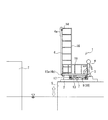
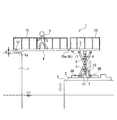
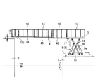
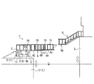
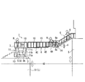
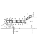
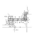
図1〜図4に例示する本発明の第1の可動式桟橋1は、船舶Sや陸地等の上に配置され、対象物T(例えば、船舶Sや陸地等)に架け渡して使用される。
The first
本発明の第1の可動式桟橋1は、船舶Sや陸地等に固定される支持台2と、支持台2に対して昇降可能に支持される基板3と、基板3から横方向に延設された橋桁部4とを備えている。可動式桟橋1はさらに、基板3を昇降させる昇降部5と、基板3の昇降移動をガイドする昇降ガイド9と、昇降部5の動作の制御を行う制御部13と、橋桁部4の先端部4aに設置される段差センサ14とを備えている。ここで、先端部4aとは橋桁部4の先端から、例えば、0.5m〜2mの範囲を示す。
The first
この実施形態では、橋桁部4の基板3との接続端4bにヒンジ部15aが備えられている。基板3および橋桁部4の両側側面にはそれぞれ手摺り16が備えられている。基板3の下面にはレーザーポインタ17が備えられている。レーザーポインタ17は任意で備えることができる。
In this embodiment, a
この実施形態の昇降部5は、基板3を支持台2に対して昇降可能に支持する一対の噛合チェーン6、6と、一対の噛合チェーン6、6を駆動させる駆動手段7とで構成されている。
The
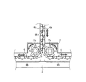
図4に示すように、一対の噛合チェーン6、6はそれぞれ、多数の駒6a、6bを回転可能に連結することにより構成されている。一対の噛合チェーン6、6は互いに噛合う状態では屈曲しない一体的な剛体になり、噛合っていない状態では屈曲可能な状態になる。それぞれの噛合チェーン6では、互いに噛合い可能な形状の2種類の駒6a、6bが長手方向に交互に連結した状態になっている。対向する噛合チェーン6、6の駒6aと駒6bとが噛合うことにより一対の噛合チェーン6、6は互いに噛合う状態になって一体化する。
As shown in FIG. 4, the pair of
駆動手段7は、例えば、それぞれの噛合チェーン6、6の駒6a、6bに噛合うスプロケット7a、7aとスプロケット7a、7aを回転駆動させるモータ部とで構成されている。それぞれの噛合チェーン6、6は、回転駆動するスプロケット7a、7aに噛合うことにより、長手方向に移動する。支持台2の表面に沿って、長手方向に移動するそれぞれの噛合チェーン6、6は、スプロケット7a、7aの間を通過することにより互いに噛合う。互いに噛合った状態の一対の噛合チェーン6、6は、上方に移動して剛体の支柱となる。それぞれのスプロケット7a、7aを反対方向に回転駆動すると、支柱になった一対の噛合チェーン6、6は下方移動してスプロケット7a、7aの間を通過する。これにより、一対の噛合チェーン6、6は互いに噛合わない分離した状態になる。
The driving means 7 is constituted by, for example,
即ち、駆動手段7は、一対の噛合チェーン6、6が互いに噛合っている状態の長さ(剛体部分6Aの長さ)および互いに噛合っていない状態の長さ(屈曲可能部分6Bの長さ)を変化させる。一対の噛合チェーン6、6が互いに噛合った状態になっている上下方向に延在する長手方向上端部が基板3に接続されて基板3が昇降可能に支持されている。
That is, the driving means 7 has a length in which the pair of
この実施形態の制御部13は、駆動手段7を制御することにより、昇降部5を制御する。即ち、支持台2と基板3との間の上下距離(剛体部分6Aの長さ)を制御する。具体的には、スプロケット7a、7bの回転量および回転速度を制御することにより、基板3の高さ位置および上下移動速度を制御する。
The
昇降ガイド9は、基板3の昇降移動を安定させるために備えられる。この実施形態の昇降ガイド9は、一対の噛合チェーン6、6の上下方向移動に対応して伸縮するパンタグラフ型昇降ガイド10で構成されている。この実施形態のパンタグラフ型昇降ガイド10はX字状に交差して設置されたフレーム10a、10bで構成されている。フレーム10aとフレーム10bの交わった部分は支軸10cによって回転可能に接続されており、フレーム10a、10bの上下端部はそれぞれ支持台2と基板3に設けられた接続部10d、10e、10f、10gに回動可能に接続されている。接続部10d、10fはそれぞれ基板3、支持台2に固定されており、接続部10e、10gはそれぞれ基板3、支持台2に長手方向にスライド可能に接続されている。このパンタグラフ型昇降ガイド10は、剛体部分6Aを挟んで両側(図1〜4の矢視では手前側と奥行き側)に備えられている。段差センサ14は、例えばレーザ距離計や超音波距離計である。
The lifting
次に、この可動式桟橋1の使用方法を、乗船している人を船舶Sから陸地等の対象物Tに移動させる場合を例にして説明する。
Next, a method of using the
まず、図1で示すように、対象物Tと所定の間隔をあけて船舶Sを停止させて、利用者Hは下方移動させて待機位置にある基板2の上に乗り移る。この際、橋桁部4はヒンジ部15aを中心にして水平状態から上方に回動させて収納された状態になっている。
First, as shown in FIG. 1, the ship S is stopped at a predetermined distance from the object T, and the user H is moved downward and transferred onto the
次に、図2で示すように、遠隔操作で制御部13を操作することにより、基板3の下面が対象物Tの上面より高くなる位置まで基板3を上昇させる。具体的には、基板3の下面と対象物Tの上面の高さ関係を目視で確認するとともにレーザーポインタ17からレーザー光線を対象物Tに向って水平に照射させて、レーザー光線が対象物Tに映りこまない高さになるまで基板3を上昇させる。波が荒い場合には、可動式桟橋1の設置場所である船舶Sが上下動するため、船舶Sが最も下方に移動した時に、対象物Tの上面より基板3の下面が高くなる位置まで基板3を上昇させる。
Next, as shown in FIG. 2, by operating the
次に、図3で示すように、上方に回動させて収納された状態になっていた橋桁部4をヒンジ部15aを中心に下方に回動させることにより橋桁部4を水平状態にして対象物Tに架け渡す。尚、ヒンジ部15aは水平状態から下方に向っては回動しない構成になっている。本発明において水平状態とは、水平から下向き傾斜角度10°程度までの状態をいう。
Next, as shown in FIG. 3, the
橋桁部4が対象物Tに架け渡されたら、段差センサ14により、橋桁部4の先端部4aと対象物Tの上面との上下距離dを検知する。段差センサ14が逐次検知した上下距離dの検知データは、制御部13に逐次入力される。そして、段差センサ14から入力された上下距離dの検知データに基づいて、制御部13により昇降部5の動きを自動的に制御することで基板3の上下位置を変化させて上下距離dを所定の許容範囲内に維持する。この許容範囲は例えば、30cm≦上下距離d≦50cmに設定する。
When the
制御部13の自動制御によって上下距離dが所定の許容範囲に維持されている状態で、利用者Hは橋桁部4と通じて船舶Sと対象物Tとの間を往来する。可動式桟橋1の利用が終了したら、架け渡しの作業手順と逆の手順で可動式桟橋1を図1で示す待機状態に戻す。
The user H travels between the ship S and the object T through the
このように本発明の第1の可動式桟橋1では、橋桁部4と対象物Tの相対的な上下位置が変化しても段差センサ14による検知データに基づいて、常に橋桁部4の先端部4aと対象物Tの上面との上下距離dを所定の許容範囲内に維持する。そのため、波により橋桁部4と対象物Tとが相対的に大きく上下揺れした場合であっても、橋桁部4と対象物Tの上面との段差が過大になることがない。さらに、基板3と橋桁部4を一体的に昇降移動させるので、このように上下揺れした場合も延在する橋桁部4が水平状態から大きく傾斜することがない。そのため、対象物Tと可動式桟橋1との間を人が安全に乗り移ることができる。
As described above, in the first
この実施形態では、昇降部5を一対の噛合チェーン6、6と駆動手段7とで構成し、基板3の昇降移動を一対の噛合チェーン6、6によって行う。そのため、橋桁部4の先端部4aと対象物Tの上面との上下距離dを所定の許容範囲内に維持する制御を精度よく行うことができる。さらに、この実施形態では、駆動手段7がスプロケット7a、7bとモータ部とで構成されており、スプロケット7a、7bの回転数、回転速度と一対の噛合チェーン6、6の移動距離、移動速度がそれぞれ比例する。そのため、剛体部分6Aの長さを変化させる制御を容易に行うことができる。
In this embodiment, the elevating
この実施形態では、橋桁部4の長手方向の所定の位置にヒンジ部15aが備えられ、このヒンジ部15aよりも先端側の部分がこのヒンジ部15aを中心にして、水平状態から上方に向った所定角度(例えば水平から上向き傾斜角度90°程度)までの範囲内で回動可能な構成になっている。そのため、例えば、突発的な波によって橋桁部4に対して対象物Tが相対的に大きく上方移動して、橋桁部4の先端部4aの下面と対象物Tの上面とが接触しても、ヒンジ部15aよりも先端部4a側の橋桁部4が上方に回動する。これにより、橋桁部4に過大な曲げ応力が発生することがないので損傷を回避するには有利になっている。ヒンジ部15aを橋桁部4と基板3との接続端4bに備えることにより、橋桁部4を使用しない場合には橋桁部4をヒンジ部15aを中心にして上方に回動させてコンパクトに収納することができる。
In this embodiment, a
可動式桟橋1は利用者Hが1人ずつに限らず、複数人で同時に利用することもできる。橋桁部4を対象物Tに架け渡す前までの作業を利用者H以外の船舶Sあるいは対象物Tにいる人が遠隔操作する構成にすることも、例えば、利用者H本人がリモートコントローラーを用いて操作する構成にすることもできる。
The
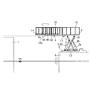
図5、6に本発明の第1の可動式桟橋1の別の実施形態を例示する。この実施形態では、図1〜4で示した実施形態と橋桁部4および昇降部5の構成が異なっている。その他の構成は同様である。
5 and 6 illustrate another embodiment of the first
この実施形態の橋桁部4は、複数の分割体4A、4B、4Cが長手方向に相対移動可能に接続されて構成されたテレスコピック構造になっている。分割体4A、4B、4Cが長手方向に相対移動することにより橋桁部4は伸縮する。それぞれの分割体4A、4B、4Cの両側側面には手摺り16が備えられている。この実施形態では3個の分割体4A、4B、4Cを有しているが、分割体は2個、4個など適宜の数にすることができる。
The
この実施形態ではさらに、橋桁部4の先端部4a(分割体4Aの先端部)に、ヒンジ部15bが備えられ、ヒンジ部15bよりも先端側の部分がこのヒンジ部15bを中心にして、水平状態から上方に向った所定角度までの範囲内で回動可能な構成になっている。具体的には、例えば、橋桁部4の先端から1m〜4mの位置にヒンジ部15bが備えられ、水平から上向き傾斜角度90°程度まで先端部4aは回動する。
Further, in this embodiment, a
この実施形態の昇降部5は、シリンダ機構8で構成されている。シリンダ機構8はシリンダロッド8aとシリンダ8bとから構成され、シリンダ8bに対するシリンダロッド8aの出し入れはサーボモータ制御または油圧制御によって行われる。シリンダロッド8aの先端部は基板3または支持台2に直接または間接的に接続される。この実施形態では、2本のシリンダ機構8が備えられており、それぞれのシリンダロッド8a、8aの先端部は、昇降ガイド10のフレーム10a、10bに接続されている。即ち、シリンダロッド8a、8aの先端部は、昇降ガイド10を介して基板3に間接的に接続されている。それぞれのシリンダ8b、8bの後端部は支持台2に対して回転可能に接続されている。
The
次に、この可動式桟橋1の使用方法を説明する。
Next, how to use the
基板3の上下位置を位置決めするまでの手順は先の実施形態と同じである。次に、水平状態で収納されていた橋桁部4を分割体4A、4B、4Cを長手方向に相対移動させることにより、橋桁部4を伸ばす。この際に橋桁部4の先端は対象物Tの上方に配置するが、先端部4aに備えたヒンジ部15bは対象物Tの上方に達しない位置(対象物Tの端面よりも船舶S側の位置)に配置する。橋桁部4をこのように対象物Tに架け渡した状態にした後は、段差センサ14により、橋桁部4の先端部4aと対象物Tの上面との上下距離dを検知する。この後の工程は、図1〜4で示した実施形態と同様である。
The procedure for positioning the upper and lower positions of the
この実施形態のように橋桁部4を、複数の分割体4A、4B、4Cを長手方向に相対移動可能に接続した状態のテレスコピック構造にすると、図5で示すように、必要に応じて橋桁部4の延設長さを最小限にすることができる。これにより、橋桁部4を短くしてコンパクトに収容できる。また、基板3と対象物Tとの距離に応じて橋桁部4の長さを調整することができるので、可動式桟橋1としての汎用性が高まる。
If the
橋桁部4の先端部4aにヒンジ部15bを備えることにより、例えば、橋桁部4に対して対象物Tが相対的に大きく上方移動して、橋桁部4の先端部4aと対象物Tの上面とが接触した場合においても、橋桁部4の先端部4aのみが上方に回動する。それ故、ヒンジ部15bよりも基板3側の橋桁部4の大部分は大きく傾斜することがなく、利用者Hが橋桁部4に居ても安全を確保するには有利になる。
By providing the
この実施形態に先の実施形態のように橋桁部4の基板3との接続端4bにヒンジ部15aを備えることもできる。先の実施形態に、この実施形態のように橋桁部4の先端部にヒンジ部15bを備えることもできる。
A
図7〜9に本発明の第2の可動式桟橋1を例示する。
The second
本発明の第2の可動式桟橋1は、船舶Sから突出したギャングウェイGの突出先端部Gpに架け渡すように使用される。ギャングウェイGとは、船舶Sと陸地Lとの間あるいは船舶Sと別の船舶S1との間を往来するために用いる橋あるいは階段である。したがって、この可動式桟橋1は別の船舶S1や陸地L等の上に配置される。この実施形態のギャングウェイGは階段状になっており、最下段部分が突出先端部Gpとなっている。
The second
本発明の第2の可動式桟橋1では、橋桁部4をギャングウェイGの突出先端部Gpの下方にオーバーラップさせるようにして使用する。そして、橋桁部4の先端部4aに取り付けられた段差センサ14は、橋桁部4の先端部4aの上面と突出先端部Gpの下面との上下距離dを測定する。段差センサ14としては、本発明の第1の可動式桟橋1の場合と同様に例えば、レーザ距離計や超音波距離計を採用する。
In the second
この実施形態の昇降ガイド9は、テレスコピック型昇降ガイド11で構成されている。テレスコピック型昇降ガイド11は、外径が互いに異なる筒状体11a、11b、11cが軸方向に相対移動可能に連結されることにより、上下方向に伸縮できる構成になっている。テレスコピック型昇降ガイド11は基板3の四隅にそれぞれ備えられている。この実施形態では3個の筒状体11a、11b、11cを有しているが、筒状体は2個、4個など適宜の数にすることができる。
The lifting
この実施形態の昇降部5は、シリンダ機構8で構成されている。シリンダロッド8aの先端部は基板3に直接接続されている。橋桁部4はテレスコピック構造になっている。
The
次に、この可動式桟橋1の使用方法を、乗船している人を船舶Sから別の船舶S1(陸地L)に移動させる場合を例にして説明する。
Next, a method of using the
まず、図7で示すように、別の船舶S1(陸地L)と所定の間隔をあけて船舶Sを停止させる。そして、船舶SからギャングウェイGを下してギャングウェイGを船舶Sに対して固定する。 First, as shown in FIG. 7, the ship S is stopped at a predetermined interval from another ship S1 (land L). Then, the gangway G is lowered from the ship S to fix the gangway G to the ship S.
次に、図8で示すように、基板3の上面が突出先端部Gpの下面よりも下方に位置する状態で、水平状態で収納されていた橋桁部4を分割体4A、4B、4Cを長手方向に相対移動させることにより、橋桁部4の先端部4aが突出先端部Gpの下方に重なる位置まで橋桁部4を伸ばす。
Next, as shown in FIG. 8, with the upper surface of the
橋桁部4が突出先端部Gpの下方にオーバーラップしたら、段差センサ14により、橋桁部4の先端部4aと突出先端部Gpの下面との上下距離dを検知する。段差センサ14が逐次検知した上下距離dの検知データは、制御部13に逐次入力される。そして、段差センサ14から入力された上下距離dの検知データに基づいて、制御部13により昇降部5の動きを自動的に制御することで基板3の上下位置を変化させて上下距離dを所定の許容範囲内に維持する。この許容範囲は例えば、30cm≦上下距離d≦50cmに設定する。
When the
制御部13の自動制御によって上下距離dが所定の許容範囲に維持されている状態で、利用者HはギャングウェイGと橋桁部4と通じて船舶Sから基板3へ乗り移る。利用者Hが基板3に乗り移った後に、図9で示すように、基板3を下降させる。そして、基板3が十分に下降した後に利用者Hは基板3から別の船舶S1(陸地L)に降りる。船舶Sに利用者Hがまだいる場合には、橋桁部4を伸ばした状態で再び制御部13による自動制御に切り替え、上下距離dを所定の許容範囲内にすることで利用者Hが突出先端部Gpから橋桁部4に乗り移れる状態にする。その後は上述した作業手順と同様の方法で行う。
The user H transfers from the ship S to the
このように本発明の第2の可動式桟橋1では、橋桁部4とギャングウェイGの相対的な上下位置が変化しても段差センサ14による検知データに基づいて、常に橋桁部4の先端部4aと突出先端部Gpの下面との上下距離dを所定の許容範囲内に維持する。そのため、波により橋桁部4とギャングウェイGが相対的に大きく上下揺れした場合であっても、橋桁部4と突出先端部Gpの下面との段差が過大になることがない。さらに、基板3と橋桁部4を一体的に昇降移動させるので、このように上下揺れした場合も延在する橋桁部4が水平状態から大きく傾斜することがない。そのため、ギャングウェイGと可動式桟橋1との間を人が安全に乗り移ることができる。
Thus, in the second
また、船舶Sが別の船舶S1あるいは陸地Lに接近することができず、ギャングウェイGのみでは船舶Sから別の船舶S1あるいは陸地Lに乗り移れない場合においても、本発明の第2の可動式桟橋1を用いることによって船舶Sから別の船舶S1あるいは陸地Lに安全に乗り移ることができる。特に、別の船舶S1が一方の船舶Sに対して非常に小さい場合は、両者の相対的な上下揺れが大きくなるので、この可動式桟橋1は極めて有益である。
In addition, even when the ship S can not approach another ship S1 or the land L, and the gangway G alone can not transfer from the ship S to another ship S1 or the land L, the second movable of the present invention can be achieved. By using the
図10に本発明の第2の可動式桟橋1の別の実施形態を例示する。
FIG. 10 illustrates another embodiment of the second
この実施形態では、図7〜9で示した実施形態と橋桁部4および昇降部5および昇降ガイド9の構成が異なっている。その他の構成は同じである。
In this embodiment, the configurations of the
この実施形態では、橋桁部4の先端部4a(分割体4Aの先端部)に、復元ヒンジ部15cが備えられている。復元ヒンジ部15cより先端側の先端部4aに所定以上の荷重が加わると復元ヒンジ部15cよりも先端側の部分がこのヒンジ部15cを中心にして、水平状態から下方に向った所定角度までの範囲内で回動可能な構成になっている。そして、水平状態から下向きに回動した先端部4aには、復元ヒンジ部15cが機能して水平状態に戻る復元力が作用する。具体的には、例えば、橋桁部4の先端から2m〜4mの位置に復元ヒンジ部15cが備えられ、復元ヒンジ部15cより先端側の先端部4aに例えば、5kg〜100kg以上の荷重が加わると水平から下向き傾斜角度90°程度まで先端部4aは回動する。
In this embodiment, a
この実施形態の昇降部5はシリンダ機構8で構成されており、シリンダロッド8aの先端部は支持台2に直接接続され、シリンダ8bの後端部は基板3に接続されている。制御部13は基板3に配置されている。
The elevating
この実施形態の昇降ガイド9は、ポスト式型昇降ガイド12で構成されている。ポスト式型昇降ガイド12は、支持台2に固定されて上下方向に延設されている支柱12aと、支柱12aに沿って上下方向移動可能に接続されているガイド部12bとで構成されている。ガイド部12bは基板3に接合されており、基板3の上下移動に伴ってガイド部12bが支柱12aに沿って上下移動する。この実施形態では、支柱12aが2本備えられており、それぞれの支柱12aに接続されているガイド部12bで基板3の昇降移動をガイドする。
The lifting
この可動式桟橋1の使用方法は図7〜9で示した実施形態と同じである。ただし、この実施形態では、橋桁部4の先端を突出先端部Gpの下方に配置する際には、復元ヒンジ部15cが突出先端部Gpの下方に達しない位置(突出先端部Gpの端面よりも別の船舶S1(陸地L)側の位置)に配置する。
The usage method of this
この実施形態では、橋桁部4の先端部4aに復元ヒンジ部15cを備えることにより、例えば、橋桁部4に対して突出先端部Gpが相対的に大きく下方移動して、橋桁部4の先端部4aの上面と突出先端部Gpの下面とが接触し、先端部4aに大きな荷重が加わった場合には、橋桁部4の先端部4aのみが下方に回動する。それ故、復元ヒンジ部15cよりも基板3側の橋桁部4の大部分は大きく傾斜することがなく、利用者Hが橋桁部4に居ても安全を確保するには有利になる。また、橋桁部4に過大な曲げ応力が発生することもないので損傷を回避するには有利になっている。
In this embodiment, by providing the
さらに、復元ヒンジ部15cは復元力を有しているので、先端部4aと突出先端部Gpの下面とが接触し、先端部4aが下方に回動する場合においても、先端部4aが過度に下方に回動することはなく、先端部4aと突出先端部Gpとの間にすき間は生じない。復元ヒンジ部15cは所定以上の荷重が加わらない限り、先端部4aが下方に回動しない構成になっている。
Furthermore, since the
尚、本発明の第1の可動式桟橋1およびの第2の可動式桟橋1で例示した昇降部5および昇降ガイド9の実施形態は、第1、第2のそれぞれの可動式桟橋1に限定されることはなく、適宜採用することができる。昇降部5と昇降ガイド9の組み合わせにおいても、上述した実施形態の組み合わせに限定されず、任意の組み合わせで構成することができる。例えば、本発明の第2の可動式桟橋1において、昇降部5を一対の噛合チェーン6、6と駆動手段7で構成し、昇降ガイド9をテレスコピック型昇降ガイド11で構成することもできる。
The embodiments of the
本発明の第2の可動式桟橋1は、橋桁部4が伸縮しない実施形態をとることもできる。橋桁部4が伸縮しない場合には、ギャングウェイGを船舶Sから降ろす前に、予め橋桁部4を伸ばしておいて、その後にギャングウェイGを船舶Sから下すことにより、橋桁部4をギャングウェイGに架け渡すことができる。この場合には、ギャングウェイGを船舶Sから下した際に橋桁部4に突出先端部Gpが衝突しないように、橋桁部4はギャングウェイGを下す位置に対して十分に低い位置に配置しておくとよい。そして、ギャングウェイGを船舶Sから下した後に制御部13による自動制御に切り替え、上下距離dを所定の許容範囲内にすることにより橋桁部4を突出先端部Gpに架け渡すようにする。
The 2nd
1 可動式桟橋
2 支持台
3 基板
4 橋桁部
4A〜4C 分割体
4a 先端部
4b 接続端
5 昇降部
6 噛合チェーン
6a、6b 駒
6A 剛体部分(互いに噛合った状態)
6B 屈曲可能部分(噛合っていない状態)
7 駆動手段
7a スプロケット
8 シリンダ機構
8a シリンダロッド
8b シリンダ
9 昇降ガイド
10 パンタグラフ型昇降ガイド
10a、10b フレーム
10c 支軸
10d〜10g 接続部
11 テレスコピック型昇降ガイド
11a〜11c 筒状体
12 ポスト式型昇降ガイド
12a 支柱
12b ガイド部
13 制御部
14 段差センサ
15a、15b ヒンジ部
15c 復元ヒンジ部
16 手摺り
17 レーザーポインタ
T 対象物
G ギャングウェイ
Gp (ギャングウェイの)突出先端部
S 船舶(ギャングウェイが設置されている船舶)
S1 別の船舶(可動式桟橋が設置されている船舶)
L 陸地
H 利用者
DESCRIPTION OF
6B Bendable part (not engaged)
7
S1 Another ship (a ship on which a movable pier is installed)
L Land H User
Claims (8)
前記基板を昇降させる昇降部と、前記基板の昇降移動をガイドする昇降ガイドと、前記昇降部の動作の制御を行う制御部と、前記橋桁部の先端部と前記対象物の上面との上下距離の検知を行う段差センサとを備え、前記段差センサによる検知データに基づいて、前記制御部により前記昇降部の動作の制御を行うことで前記基板の上下位置を変化させて前記上下距離を所定の許容範囲内に維持する構成にしたことを特徴とする可動式桟橋。 The bridge girder is provided with a substrate supported movably with respect to the support and a bridge girder portion extending in the lateral direction of the substrate, with the tip of the bridge girder positioned above the object. A mobile pier that allows people to travel to and from the object through the department;
An elevation unit for raising and lowering the substrate, an elevation guide for guiding the elevation movement of the substrate, a control unit for controlling the operation of the elevation unit, and an upper and lower distance between the tip of the bridge girder and the upper surface of the object And the control unit controls the operation of the elevating unit based on the detection data from the step sensor to change the upper and lower positions of the substrate to make the upper and lower distance predetermined. A movable pier characterized in that it is configured to be maintained within an acceptable range.
前記基板を昇降させる昇降部と、前記基板の昇降移動をガイドする昇降ガイドと、前記昇降部の動作の制御を行う制御部と、前記橋桁部の先端部と前記ギャングウェイの突出先端部の下面との上下距離の検知を行う段差センサとを備え、前記段差センサによる検知データに基づいて、前記制御部により前記昇降部の動作の制御を行うことで前記基板の上下位置を変化させて前記上下距離を所定の許容範囲内に維持する構成にしたことを特徴とする可動式桟橋。 The support base includes a substrate supported so as to be movable up and down, and a bridge girder extending in the lateral direction of the substrate, and the tip of the bridge girder is positioned below the protruding tip of the gangway protruding from the ship. A movable pier that allows people to travel to and from the gangway through the bridge girder,
A lifting unit for lifting the substrate, a lifting guide for guiding the lifting movement of the substrate, a control unit for controlling the operation of the lifting unit, a tip of the bridge girder and a lower surface of the protruding tip of the gangway And controlling the operation of the elevating unit by the control unit based on the detection data from the step sensor, thereby changing the vertical position of the substrate to change the vertical position of the substrate. A movable pier characterized in that the distance is maintained within a predetermined tolerance.
Priority Applications (1)
| Application Number | Priority Date | Filing Date | Title |
|---|---|---|---|
| JP2015180296A JP6516640B2 (en) | 2015-09-14 | 2015-09-14 | Mobile pier |
Applications Claiming Priority (1)
| Application Number | Priority Date | Filing Date | Title |
|---|---|---|---|
| JP2015180296A JP6516640B2 (en) | 2015-09-14 | 2015-09-14 | Mobile pier |
Publications (2)
| Publication Number | Publication Date |
|---|---|
| JP2017057553A JP2017057553A (en) | 2017-03-23 |
| JP6516640B2 true JP6516640B2 (en) | 2019-05-22 |
Family
ID=58391160
Family Applications (1)
| Application Number | Title | Priority Date | Filing Date |
|---|---|---|---|
| JP2015180296A Active JP6516640B2 (en) | 2015-09-14 | 2015-09-14 | Mobile pier |
Country Status (1)
| Country | Link |
|---|---|
| JP (1) | JP6516640B2 (en) |
Families Citing this family (4)
| Publication number | Priority date | Publication date | Assignee | Title |
|---|---|---|---|---|
| CN107988891B (en) * | 2017-12-29 | 2023-07-11 | 浙江省水利水电勘测设计院有限责任公司 | Lifting and moving combined movable steel bridge |
| JP6882795B2 (en) * | 2019-09-30 | 2021-06-02 | 村田油圧機械株式会社 | Contact bridge |
| JP6798721B1 (en) * | 2019-09-30 | 2020-12-09 | 村田油圧機械株式会社 | Horizontal rotation actuator for connecting bridge |
| JP6798720B1 (en) * | 2019-09-30 | 2020-12-09 | 村田油圧機械株式会社 | Telescopic actuator for connecting bridge |
Family Cites Families (10)
| Publication number | Priority date | Publication date | Assignee | Title |
|---|---|---|---|---|
| JPS523319Y2 (en) * | 1972-09-13 | 1977-01-24 | ||
| JPS5416319B2 (en) * | 1973-10-25 | 1979-06-21 | ||
| JPS546326A (en) * | 1977-06-15 | 1979-01-18 | Ishikawajima Harima Heavy Ind | Moving bridge |
| US4133067A (en) * | 1977-12-16 | 1979-01-09 | Bennett Ronald W | Articulating gangway |
| JPS6198692A (en) * | 1984-10-19 | 1986-05-16 | Nippon Kokan Kk <Nkk> | Accommodation ladder device |
| JPH0351404A (en) * | 1989-07-18 | 1991-03-05 | Ishikawajima Harima Heavy Ind Co Ltd | Passenger transport device |
| JP2003027417A (en) * | 2001-05-10 | 2003-01-29 | River Corporation:Kk | Connecting bridge between pier and marine vessel |
| JP6038707B2 (en) * | 2013-03-29 | 2016-12-07 | 株式会社椿本チエイン | Engagement chain type lifting device |
| JP2015030304A (en) * | 2013-07-31 | 2015-02-16 | ダイハツ工業株式会社 | Carriage truck of automobile body |
| JP6336280B2 (en) * | 2014-01-20 | 2018-06-06 | 東亜建設工業株式会社 | Movable pier |
-
2015
- 2015-09-14 JP JP2015180296A patent/JP6516640B2/en active Active
Also Published As
| Publication number | Publication date |
|---|---|
| JP2017057553A (en) | 2017-03-23 |
Similar Documents
| Publication | Publication Date | Title |
|---|---|---|
| JP6516640B2 (en) | Mobile pier | |
| CN101125603B (en) | Article storage facility and operation method thereof | |
| JP4333720B2 (en) | Mounting structure of lifting platform in transfer equipment | |
| RU2017102916A (en) | LEVELING GROUP FOR Aerial platforms | |
| RU2013129448A (en) | FAST TRANSPORT DRILLING RIG | |
| JP6487798B2 (en) | Movable pier | |
| CN106917499B (en) | A kind of self-driving type full-automatic machine people's climbing frame | |
| JP2008214056A (en) | Portal lifter | |
| JP2008050111A (en) | Step eliminating device | |
| CN112850511A (en) | Hoisting method adopting portable crane | |
| JP2015055063A (en) | Slide type multistage overhang scaffold | |
| CN102310844A (en) | Blocking device | |
| WO2020042683A1 (en) | Industrial robot repair and maintenance device | |
| JP2012062159A (en) | Lift platform lifting drive device of level difference resolving machine | |
| TWI570047B (en) | The Manufacturing Method and Disassembling Method of Giant Crane Crane | |
| JP2007113345A (en) | Parking device and lift | |
| KR101350463B1 (en) | Central limit device | |
| KR20220022489A (en) | Jack-up rig | |
| JP2014227296A (en) | Holding mechanism for telescopic mast | |
| JP2014224372A (en) | Stair mobile scaffolding | |
| RU2307062C2 (en) | Device for lifting and laying mast and lifting boom of lifting crane | |
| JP2017120012A (en) | Ship Passenger Boarding Bridge | |
| JP5962474B2 (en) | Elevator safety fence | |
| JP4213538B2 (en) | Pallet changer | |
| JP2015037463A (en) | Level difference eliminating lift |
Legal Events
| Date | Code | Title | Description |
|---|---|---|---|
| A621 | Written request for application examination |
Free format text: JAPANESE INTERMEDIATE CODE: A621 Effective date: 20180517 |
|
| A977 | Report on retrieval |
Free format text: JAPANESE INTERMEDIATE CODE: A971007 Effective date: 20190124 |
|
| A131 | Notification of reasons for refusal |
Free format text: JAPANESE INTERMEDIATE CODE: A131 Effective date: 20190212 |
|
| A521 | Request for written amendment filed |
Free format text: JAPANESE INTERMEDIATE CODE: A523 Effective date: 20190319 |
|
| TRDD | Decision of grant or rejection written | ||
| A01 | Written decision to grant a patent or to grant a registration (utility model) |
Free format text: JAPANESE INTERMEDIATE CODE: A01 Effective date: 20190402 |
|
| A61 | First payment of annual fees (during grant procedure) |
Free format text: JAPANESE INTERMEDIATE CODE: A61 Effective date: 20190416 |
|
| R150 | Certificate of patent or registration of utility model |
Ref document number: 6516640 Country of ref document: JP Free format text: JAPANESE INTERMEDIATE CODE: R150 |
|
| R250 | Receipt of annual fees |
Free format text: JAPANESE INTERMEDIATE CODE: R250 |
|
| R250 | Receipt of annual fees |
Free format text: JAPANESE INTERMEDIATE CODE: R250 |
|
| R250 | Receipt of annual fees |
Free format text: JAPANESE INTERMEDIATE CODE: R250 |
