JP6515552B2 - Product storage device - Google Patents

Product storage device Download PDF

Info

Publication number
JP6515552B2
JP6515552B2 JP2015014458A JP2015014458A JP6515552B2 JP 6515552 B2 JP6515552 B2 JP 6515552B2 JP 2015014458 A JP2015014458 A JP 2015014458A JP 2015014458 A JP2015014458 A JP 2015014458A JP 6515552 B2 JP6515552 B2 JP 6515552B2
Authority
JP
Japan
Prior art keywords
product
sold
spiral
base
storage device
Prior art date
Legal status (The legal status is an assumption and is not a legal conclusion. Google has not performed a legal analysis and makes no representation as to the accuracy of the status listed.)
Active
Application number
JP2015014458A
Other languages
Japanese (ja)
Other versions
JP2016139315A (en
Inventor
史基 市原
史基 市原
武藤 健二
健二 武藤
智憲 大坪
智憲 大坪
Current Assignee (The listed assignees may be inaccurate. Google has not performed a legal analysis and makes no representation or warranty as to the accuracy of the list.)
Fuji Electric Co Ltd
Original Assignee
Fuji Electric Co Ltd
Priority date (The priority date is an assumption and is not a legal conclusion. Google has not performed a legal analysis and makes no representation as to the accuracy of the date listed.)
Filing date
Publication date
Application filed by Fuji Electric Co Ltd filed Critical Fuji Electric Co Ltd
Priority to JP2015014458A priority Critical patent/JP6515552B2/en
Priority to CN201511020230.5A priority patent/CN105825588B/en
Publication of JP2016139315A publication Critical patent/JP2016139315A/en
Application granted granted Critical
Publication of JP6515552B2 publication Critical patent/JP6515552B2/en
Active legal-status Critical Current
Anticipated expiration legal-status Critical

Links

Images

Classifications

    • GPHYSICS
    • G07CHECKING-DEVICES
    • G07FCOIN-FREED OR LIKE APPARATUS
    • G07F11/00Coin-freed apparatus for dispensing, or the like, discrete articles
    • G07F11/46Coin-freed apparatus for dispensing, or the like, discrete articles from movable storage containers or supports
    • G07F11/50Coin-freed apparatus for dispensing, or the like, discrete articles from movable storage containers or supports the storage containers or supports being rotatably mounted
    • G07F11/54Coin-freed apparatus for dispensing, or the like, discrete articles from movable storage containers or supports the storage containers or supports being rotatably mounted about vertical axes

Landscapes

  • Physics & Mathematics (AREA)
  • General Physics & Mathematics (AREA)
  • Vending Machines For Individual Products (AREA)
  • Control Of Vending Devices And Auxiliary Devices For Vending Devices (AREA)

Description

本発明は、商品収納装置に関し、より詳細には、商品の販売を行う自動販売機に適用される商品収納装置に関するものである。   The present invention relates to a product storage device, and more particularly to a product storage device applied to a vending machine that sells products.

従来、商品の販売を行う自動販売機には、商品収容庫の商品ラックに収納された商品を搬送トレイに繰り出した後、搬送トレイによって搬送して所定の商品取出領域に払い出すようにしたものがある。商品取出領域は、商品取出口を介して商品収容庫の外部に連通された空間であり、利用者が商品取出口から手を差し入れれば、購入した商品の取り出しが可能である。   Conventionally, in an automatic vending machine that sells goods, after the goods stored in the goods rack of the goods storage are drawn out to the conveyance tray, they are conveyed by the conveyance tray and paid out to a predetermined goods extraction area There is. The product takeout area is a space communicated with the outside of the product storage via the product takeout port, and if the user inserts a hand from the product takeout port, the purchased product can be taken out.

通常、この種の自動販売機では、前面を構成する扉体がガラス等の透明な面板によって構成されており、商品収容庫の商品ラックに収納された商品を外部から視認して選択することが可能であり、更に、商品ラックから繰り出された購入商品が搬送トレイによって商品取出領域まで搬送される状態を観察することができる。このように商品収容庫の内部が視認可能な自動販売機によれば、利用者の購買意欲を高めることができる等の利点がある。   Usually, in this type of vending machine, the door constituting the front face is constituted by a transparent face plate such as glass, and the product stored in the product rack of the product storage can be visually recognized and selected from the outside It is possible to observe a state in which purchased goods delivered from the product rack are transported to the product unloading area by the transport tray. As described above, according to the vending machine in which the inside of the product storage can be visually recognized, there is an advantage that the user's willingness to purchase can be enhanced.

このような自動販売機における商品ラックは、複数の商品収納装置が左右に並設されて構成されている。商品ラックを構成する各商品収納装置は、スパイラルを備えて構成されている。スパイラルは、前後方向に沿って螺旋状に巻回される態様で構成されている。このスパイラルは、伝達機構を介して駆動源であるモータより駆動力が伝達された場合に中心軸回りに回転するものである。   A commodity rack in such a vending machine is configured by arranging a plurality of commodity storage devices side by side. Each product storage device constituting the product rack is configured to include a spiral. The spiral is configured in a manner of being spirally wound along the front-rear direction. The spiral rotates around the central axis when the driving force is transmitted from the motor as the driving source through the transmission mechanism.

このような構成を有する商品収納装置では、常態においてはスパイラルの各ピッチ間に商品を拘束しており、スパイラルが回転する場合には各ピッチ間に拘束された商品を漸次前方に向けて搬出して最前の商品を払い出すようにしている(例えば、特許文献1参照)。   In the product storage device having such a configuration, in the normal state, the product is restrained between the pitches of the spiral, and when the spiral rotates, the product constrained between the pitches is gradually taken out toward the front. The first product is paid out (see, for example, Patent Document 1).

特許第3978932号公報Patent No. 3978932

上述した商品収納装置においては、スパイラルにおける最前のピッチ間における商品の有無を検知する売切検知スイッチが設けられているのが一般的である。この売切検知スイッチが最前のピッチ間について商品無しと検知した場合、商品収納装置ではスパイラルに拘束された商品は全て払い出されて売切状態にあるものとして所定の売切処理が行われる。   In the above-described product storage device, it is general that a sold-out detection switch is provided which detects the presence or absence of a product between the foremost pitches in the spiral. When the sold-out detection switch detects that there is no product for the frontmost pitch, in the product storage device, all the products constrained by the spiral are paid out and a predetermined sold-out process is performed assuming that they are sold out.

また上記商品収納装置では、各ピッチ間の長さが異なる複数種類のスパイラルを設置することが可能であり、収納対象となる商品の大きさ等に応じて最適なスパイラルが設置されるのが一般的である。   Further, in the above-mentioned product storage device, it is possible to install a plurality of types of spirals having different lengths between each pitch, and it is general that an optimal spiral is installed according to the size etc. of the product to be stored. It is

しかしながら、売切検知スイッチについては、製造コストの低減等の観点より、設置されるスパイラルのピッチ間により使い分けられずに設置可能な全てのスパイラルに対して共通に用いられている。   However, the sellout detection switch is commonly used for all the spirals that can be installed without being used properly depending on the pitch of the spirals installed from the viewpoint of reduction of manufacturing cost and the like.

このように売切検知スイッチが設置可能な全てのスパイラルに対して共通に用いられる場合には、回転するスパイラルが後方側から前方側に向けて商品を搬出する特性等を考慮して、ピッチ間の長さが最も大きいスパイラルの最前のピッチ間における商品の有無を検知することが可能な個所に売切検知スイッチが配設されることとなる。   As described above, in the case where the sold-out detection switch is used in common to all the installable spirals, the pitch between the pitches is considered in consideration of the characteristic that the rotating spiral moves the product from the rear side to the front side. The sold-out detection switch is disposed at a position where it is possible to detect the presence or absence of a product between the foremost pitches of the spiral having the largest length.

そのため、ピッチ間の長さが比較的小さいスパイラルが設置された商品収納装置では、売切検知スイッチは、最前のピッチ間ではなくて最前から2番目あるいは3番目のピッチ間の商品の有無を検知してしまうことがあり、結果として最前のピッチ間に商品が拘束されていないで最前から2番目のピッチ間に商品が拘束されている場合にも商品有りと検知してしまうことがある。   Therefore, in the product storage device in which a spiral having a relatively small length between pitches is installed, the sold-out detection switch detects the presence or absence of a product between the foremost second pitch or the third pitch instead of the foremost pitch. As a result, the product may be detected as being present even when the product is not constrained between the foremost pitches and the product is constrained between the foremost second pitches.

このように最前のピッチ間に商品が拘束されずに最前から2番目のピッチ間に商品が拘束されていて売切検知スイッチが商品有りと検知する場合、当該商品収納装置は、販売可能な状態であると判断され、払出指令が与えられることでスパイラルを回転させてしまう。そして、スパイラルを回転させても最前のピッチ間には商品が拘束されていないので、商品は払い出されない。これでは商品選択を行った購入者は、金銭を支払っても商品を得ることができず、利用者に対し不測の不利益を与えることとなり好ましくない。   As described above, when the product is restrained between the first pitch and the second pitch without the product being restrained between the foremost pitches and the sold-out detection switch detects that the commodity is present, the product storage device can be sold It is determined that is, and a spiral is rotated by giving a payout command. Then, even if the spiral is rotated, since the product is not restrained between the foremost pitches, the product is not dispensed. In this case, the purchaser who made the product selection can not obtain the product even if he / she pays money, which is unpreferable because it gives the user an unexpected disadvantage.

そこで、商品収納装置からの商品の払い出しを検知できない場合には、投入された金銭を返却するようにすることも可能であるが、昨今普及している電子マネーでの決済では、払出指令が与えられる時点で既に減算処理が成立しているため、金銭の返却を行うことができず、結果的に利用者に対して不測の不利益を与えることとなる。   Therefore, if it is not possible to detect the delivery of the product from the product storage device, it is possible to return the inserted money, but in the settlement with electronic money that has become widespread recently, a payout command is given. Since the subtraction process has already been established at the point of time, money can not be returned, and as a result, the user is unexpectedly disadvantaged.

本発明は、上記実情に鑑みて、売切検知手段が商品有りと検知する状態で払出指令が与えられた場合には、商品の払い出しを確実に行って利用者が不測の不利益を被ることを防止することができる商品収納装置を提供することを目的とする。   In the present invention, in view of the above situation, when a dispensing command is given in a state where the sold-out detection means detects that there is a product, the product is reliably delivered and the user suffers an unexpected disadvantage. It is an object of the present invention to provide a product storage device capable of preventing the

上記目的を達成するために、本発明に係る商品収納装置は、前後方向に沿って螺旋状に巻回される態様で構成され、かつ伝達機構を介して駆動源より駆動力が伝達された場合に中心軸回りに回転するスパイラルを備え、払出指令に応じて前記スパイラルを回転させることにより該スパイラルのピッチ間に拘束された商品を漸次前方に向けて搬出して最前のピッチ間の商品を払い出す商品収納装置であって、前記スパイラルにおける最前域のいずれかのピッチ間の商品の有無を検知する売切検知手段と、前記スパイラルから払い出された商品を検知する払出検出手段と、前記売切検知手段が商品有りと検知する状態で前記払出指令が与えられた場合に、前記駆動源を駆動させて前記スパイラルを回転させた結果前記払出検出手段により商品が検知されないときには、前記駆動源を再度駆動させて前記払出検出手段により商品が検知されるまで前記スパイラルを回転させる再試行処理を行う制御手段とを備えたことを特徴とする。   In order to achieve the above object, the product storage device according to the present invention is configured in a manner of being spirally wound along the front-rear direction, and when a driving force is transmitted from a driving source via a transmission mechanism. The product has a spiral that rotates about its central axis, and by rotating the spiral according to the dispensing command, the product constrained between the pitches of the spiral is gradually carried forward toward the front to clear the product between the foremost pitches. A product storage device for emitting goods, which is a sold-out detection means for detecting presence or absence of goods between any pitches in the front area of the spiral, a payout detection means for detecting goods dispensed from the spiral, and the sales The product is detected by the payout detecting means as a result of driving the drive source and rotating the spiral when the dispensing instruction is given in a state where the disconnection detecting means detects that there is a commodity. When not in is characterized in that a control means for performing a retry process of rotating the spiral to the commodity is detected by the payout detection means by driving the drive source again.

また本発明は、上記商品収納装置において、前記制御手段は、前記売切検知手段が商品無しと検知する場合には、所定の上位機器に対して売切状態である旨を送出することを特徴とする。   Further, the present invention is characterized in that, in the above-mentioned product storage device, the control means sends out a sold out state to a predetermined upper device when the sold-out detection means detects that there is no product. I assume.

また本発明は、上記商品収納装置において、前記スパイラルの内部を貫通する態様で前後方向に沿って延在し、かつ上面に商品を載置させるベースと、前記ベースの上方域に進退移動する態様で該ベースに揺動可能に配設され、かつ常態においては付勢手段に付勢されて進出姿勢となる一方、最前域のいずれかのピッチ間の商品に押圧される場合には前記付勢手段の付勢力に抗して前記進出姿勢から退行移動する売切アクチュエータとを備え、前記売切検知手段は、前記売切アクチュエータが前記進出姿勢から退行移動する場合には商品有りと検知する一方、前記売切アクチュエータが進出姿勢となる場合には商品無しと検知することを特徴とする。   Further, according to the present invention, in the product storage device, the base extends along the front-rear direction in a manner to penetrate the inside of the spiral, and a base for placing the product on the upper surface, and advancing and retracting to the upper region of the base In the normal state, it is biased by the biasing means to be in the advancing position, while in the case of being pressed by a product between any pitch in the foremost area, the biasing A sold-out actuator that moves backward from the advancing position against the biasing force of the means, and the sold-out detection unit detects that there is a product when the sold-out actuator moves backward from the advanced posture When the sold-out actuator is in the advanced position, it is detected that there is no product.

本発明によれば、制御手段が、スパイラルにおける最前域のいずれかのピッチ間の商品の有無を検知する売切検知手段が商品有りと検知する状態で払出指令が与えられた場合に、駆動源を駆動させてスパイラルを回転させた結果、スパイラルから払い出された商品を検出する払出検出手段により商品が検出されないときには、駆動源を再度駆動させて払出検出手段により商品が検出されるまでスパイラルを回転させる再試行処理を行うので、次のような効果を奏する。すなわち、スパイラルの最前のピッチ間には商品が拘束されずに最前から2番目や3番目のピッチ間に商品が拘束されるいわゆる「歯抜け」状態で商品が収納されている場合において、一旦払出指令が与えられれば、商品が払い出されるまでスパイラルを回転させることができ、これにより、売切検知手段が商品有りと検知する状態で払出指令が与えられた場合には、商品の払い出しを確実に行って利用者が不測の不利益を被ることを防止することができるという効果を奏する。   According to the present invention, the drive source is selected when the dispensing command is given in a state in which the selling out detection unit that detects presence or absence of the product between any pitches in the front area of the spiral detects that the product is present. When the product is not detected by the payout detection means for detecting the product paid out from the spiral as a result of rotating the spiral by driving the drive, the drive source is driven again and the spiral is run until the product is detected by the payout detection means. Since the retry process of rotating is performed, the following effects can be obtained. That is, if the product is stored in a so-called "dropout" state in which the product is not confined between the foremost pitches of the spiral and the product is confined between the second and third from the front without being restricted If a command is given, it is possible to rotate the spiral until the product is paid out, thereby ensuring that the product is paid out when a payout command is given in a state where the sold-out detection means detects that the product is present. The effect is that the user can be prevented from suffering unexpected disadvantages.

図1は、本発明の実施の形態である商品収納装置が適用された自動販売機の内部構造を模式的に示す断面側面図である。FIG. 1 is a cross-sectional side view schematically showing an internal structure of a vending machine to which a commodity storage apparatus according to an embodiment of the present invention is applied. 図2は、商品ラックを構成する1つの商品収納装置を示す斜視図である。FIG. 2 is a perspective view showing one product storage device that constitutes a product rack. 図3は、図2に示したコラムケースを示す斜視図である。FIG. 3 is a perspective view showing the column case shown in FIG. 図4は、図2に示した駆動ユニットを示す斜視図である。FIG. 4 is a perspective view showing the drive unit shown in FIG. 図5は、図2に示した駆動ユニットを示す斜視図である。FIG. 5 is a perspective view showing the drive unit shown in FIG. 図6は、図4及び図5に示した駆動ユニットの内部構造を示す斜視図である。FIG. 6 is a perspective view showing the internal structure of the drive unit shown in FIGS. 4 and 5. 図7は、図4及び図5に示した駆動ユニットの内部構造を示す斜視図である。FIG. 7 is a perspective view showing the internal structure of the drive unit shown in FIGS. 4 and 5. 図8は、図2に示したベースユニットを右側下方から見た場合を示す斜視図である。FIG. 8 is a perspective view showing the base unit shown in FIG. 2 as viewed from the lower right side. 図9は、図2及び図8に示したベースユニットを構成するベースを示す斜視図である。FIG. 9 is a perspective view showing a base constituting the base unit shown in FIGS. 2 and 8. 図10は、図8に示したスライダの前端部分の主要な構成要素を示す斜視図である。FIG. 10 is a perspective view showing the main components of the front end portion of the slider shown in FIG. 図11は、図10に示したスライダ及び売切アクチュエータを示す斜視図である。FIG. 11 is a perspective view showing the slider and the sold-out actuator shown in FIG. 図12は、図8に示したスライダの前端部分の主要な構成要素を示す斜視図である。FIG. 12 is a perspective view showing the main components of the front end portion of the slider shown in FIG. 図13は、スライダ及び売切アクチュエータの動作を模式的に示す模式図である。FIG. 13 is a schematic view schematically showing the operation of the slider and the sold-out actuator. 図14は、スライダ及び売切アクチュエータの動作を模式的に示す模式図である。FIG. 14 is a schematic view schematically showing the operation of the slider and the sold-out actuator. 図15は、支持部材を示す斜視図である。FIG. 15 is a perspective view showing a support member. 図16は、ベースユニットを構成するベースの支持構造を示す斜視図である。FIG. 16 is a perspective view showing a support structure of a base constituting the base unit. 図17は、本発明の実施の形態である商品収納装置の特徴的な制御系を示すブロック図である。FIG. 17 is a block diagram showing a characteristic control system of the commodity storage apparatus according to the embodiment of the present invention. 図18は、商品収納装置の商品収納制御部が実施する商品払出制御処理の処理内容を示すフローチャートである。FIG. 18 is a flowchart showing the processing content of the commodity delivery control processing carried out by the commodity storage control unit of the commodity storage device. 図19は、スライダ及び売切アクチュエータの動作を模式的に示す模式図である。FIG. 19 is a schematic view schematically showing the operation of the slider and the sold-out actuator. 図20は、スライダ及び売切アクチュエータの動作を模式的に示す模式図である。FIG. 20 is a schematic view schematically showing the operation of the slider and the sold-out actuator.

以下に添付図面を参照して、本発明に係る商品収納装置の好適な実施の形態について詳細に説明する。   Hereinafter, preferred embodiments of a product storage device according to the present invention will be described in detail with reference to the attached drawings.

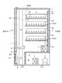
図1は、本発明の実施の形態である商品収納装置が適用された自動販売機の内部構造を模式的に示す断面側面図である。ここで例示する自動販売機は、本体キャビネット1を備えて構成してある。   FIG. 1 is a cross-sectional side view schematically showing an internal structure of a vending machine to which a commodity storage apparatus according to an embodiment of the present invention is applied. The vending machine illustrated here is configured to include a main body cabinet 1.

本体キャビネット1は、前面が開口した直方状の自動販売機本体であり、その内部に断熱構造の商品収容庫2が配設してある。商品収容庫2には、商品ラック10が上下方向に沿って複数段設けてある。これら商品ラック10は、それぞれ商品収容庫2の両側に立設された図示せぬラック支持側板間に架設されており、商品を収納するものである。   The main body cabinet 1 is a rectangular automatic vending machine main body whose front surface is opened, and a commodity storage case 2 of a heat insulating structure is disposed inside thereof. The product storage case 2 is provided with a plurality of product racks 10 along the vertical direction. Each of the product racks 10 is installed between rack support side plates (not shown) erected on both sides of the product storage 2 to store products.

また、商品収容庫2には冷却手段としての蒸発器3が設けてある。蒸発器3は、機械室4に配設された圧縮機5や凝縮器6等と冷媒を循環させる冷凍サイクルを構成しており、自身の図示せぬ冷媒通路を通過する冷媒と、自身の周囲を通過する商品収容庫2の内部の空気とを熱交換させて該空気を冷却させるものである。ここで機械室4は、本体キャビネット1の内部において商品収容庫2の下方側に画成された室である。   Further, the commodity storage case 2 is provided with an evaporator 3 as a cooling means. The evaporator 3 constitutes a refrigeration cycle for circulating the refrigerant with the compressor 5, the condenser 6 and the like disposed in the machine chamber 4, and the refrigerant passing through the refrigerant passage (not shown) of its own, and its surroundings Heat exchange with the air inside the product storage 2 passing through to cool the air. Here, the machine room 4 is a room defined on the lower side of the commodity storage 2 inside the main body cabinet 1.

蒸発器3の周囲で冷却された空気は、庫内送風ファン7が駆動することにより、商品収容庫2の背面に設置された背面ダクト8の吸込口8aより通風路9に吸い込まれ、この通風路9を通過した後に吹出口8bから吹き出されることにより、商品ラック10に収納された商品を冷却することになる。   The air cooled in the periphery of the evaporator 3 is sucked into the ventilation path 9 from the suction port 8a of the rear duct 8 installed on the rear surface of the product storage 2 by driving the storage fan 7 inside. By blowing out from the outlet 8 b after passing through the passage 9, the goods stored in the goods rack 10 are cooled.

上記商品ラック10の前方域には、その両側に左右一対となる態様で搬送レール11が配設してあり、これら搬送レール11間を搬送トレイ12が図示せぬ搬送機構により上下方向に沿って移動可能に配設してある。つまり、搬送レール11間には、搬送トレイ12を通過させるための搬送通路13が形成してある。この搬送通路13は、機械室4の前方まで延在しており、搬送通路13と機械室4とは区画断熱材4aにより区画されている。   In the front area of the product rack 10, conveyance rails 11 are disposed on both sides in a form of right and left pair, and between the conveyance rails 11 along the vertical direction by the conveyance mechanism (not shown). It is arranged movably. That is, between the carrying rails 11, a carrying passage 13 for passing the carrying tray 12 is formed. The transfer passage 13 extends to the front of the machine chamber 4, and the transfer passage 13 and the machine chamber 4 are partitioned by the partition heat insulating material 4 a.

上記本体キャビネット1には、扉体14及び閉塞部材15が設けてある。扉体14は、本体キャビネット1の前面開口の上方部、より詳細には商品収容庫2の前方域を開閉するもので本体キャビネット1の一側縁部に開閉移動に配設してある。この扉体14は、断熱構造を有するものであり、外部より内部の視認を可能にする断熱性のガラス板(図示せず)を備えている。   The main body cabinet 1 is provided with a door 14 and a closing member 15. The door 14 opens and closes the upper part of the front opening of the main body cabinet 1, more specifically, the front area of the commodity storage 2, and is disposed at one side edge of the main body cabinet 1. The door 14 has a heat insulating structure, and is provided with a heat insulating glass plate (not shown) that allows the inside to be viewed from the outside.

閉塞部材15は、本体キャビネット1の前面開口の下方部、より詳細には、上記扉体14で閉塞することができない本体キャビネット1の前面開口の下方部を閉塞するものである。よって、閉塞部材15は、機械室4の前方に形成される搬送通路13の前方を閉塞している。   The closing member 15 closes the lower part of the front opening of the main cabinet 1, more specifically, the lower part of the front opening of the main cabinet 1 which can not be closed by the door 14 described above. Therefore, the closing member 15 closes the front of the transfer passage 13 formed in the front of the machine chamber 4.

この閉塞部材15には、矩形状の商品取出口15aが形成してある。この商品取出口15aは、搬送トレイ12を通じて搬送された商品を利用者が取り出すための開口であり、商品取出扉16により開閉されるものである。   The closure member 15 is formed with a rectangular product outlet 15a. The product outlet 15 a is an opening for the user to take out the product transported through the transport tray 12, and is opened and closed by the product outlet door 16.

上記商品ラック10は、複数の商品収納装置20が左右に並ぶ態様で並設されることにより構成してある。図2は、商品ラック10を構成する1つの商品収納装置20を示す斜視図である。ここで例示する商品収納装置20は、コラムケース30と、駆動ユニット40と、スパイラル50と、ベースユニット60と、支持部材70(図15参照)とを備えて構成してある。   The product rack 10 is configured by arranging a plurality of product storage devices 20 side by side in a line. FIG. 2 is a perspective view showing one product storage device 20 that constitutes the product rack 10. The commodity storage device 20 illustrated here is configured to include a column case 30, a drive unit 40, a spiral 50, a base unit 60, and a support member 70 (see FIG. 15).

コラムケース30は、例えば樹脂材等により形成され、前後方向が長手方向となる長尺状のものである。このコラムケース30は、図3に示すように、前端部に下方に向けて突出する取付部31が設けてあるとともに、後端部に駆動ユニット40を収納する収納部32が設けてあり、上方域に商品を収納するための商品収納通路を構成するためのものである。かかるコラムケース30は、商品ラック10を構成するラック底板10a(図1参照)に取付部31が取り付けられるものである。   The column case 30 is formed of, for example, a resin material, and is long in the longitudinal direction. As shown in FIG. 3, the column case 30 is provided with a mounting portion 31 projecting downward at the front end, and a storage portion 32 for storing the drive unit 40 at the rear end. It is for comprising the goods storage passage for storing goods in a field. The mounting portion 31 is attached to the rack bottom plate 10 a (see FIG. 1) which constitutes the product rack 10.

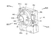
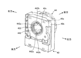
図4及び図5は、それぞれ図2に示した駆動ユニット40を示す斜視図であり、図6及び図7は、それぞれ図4及び図5に示した駆動ユニット40の内部構造を示す斜視図である。これら図4〜図7を適宜用いて駆動ユニット40について説明する。   4 and 5 are perspective views showing the drive unit 40 shown in FIG. 2, and FIGS. 6 and 7 are perspective views showing the internal structure of the drive unit 40 shown in FIGS. 4 and 5, respectively. is there. The drive unit 40 will be described using FIG. 4 to FIG. 7 as appropriate.

駆動ユニット40は、モータ41と、出力ギア42と、搬出検知スイッチ(搬出検知手段)43と、伝達部材44とを備えて構成してある。モータ41は、後述する商品収納制御部80から与えられる駆動指令により駆動する駆動源である。このモータ41は、前後一対の駆動ケース40a,40bの内部に収納されている。   The drive unit 40 includes a motor 41, an output gear 42, a carry-out detection switch (carried out detection means) 43, and a transmission member 44. The motor 41 is a drive source driven by a drive command given from a product storage control unit 80 described later. The motor 41 is housed inside the pair of front and rear drive cases 40a and 40b.

出力ギア42は、略円環状の形態を成しており、外周縁部分に第1出力歯部421が形成してあるとともに内周縁部分に第2出力歯部422が形成してある。この出力ギア42は、第2出力歯部422が駆動ケース40a,40bに形成された貫通孔40cの内面から露出する態様で駆動ケース40a,40bの内部に収納されている。ここで貫通孔40cは、駆動ケース40a,40bの略中央部分において前後方向に沿って延在するものである。   The output gear 42 has a substantially annular shape, and the first output tooth portion 421 is formed on the outer peripheral edge portion and the second output tooth portion 422 is formed on the inner peripheral edge portion. The output gear 42 is housed inside the drive cases 40a and 40b in such a manner that the second output teeth 422 are exposed from the inner surface of the through hole 40c formed in the drive cases 40a and 40b. Here, the through holes 40c extend in the front-rear direction at substantially central portions of the drive cases 40a and 40b.

上記出力ギア42は、上記モータ41と連係ギアユニット45を介して連係してある。連係ギアユニット45は、モータ41の出力軸411に噛合された第1連係ギア451と、第1連係ギア451に噛合された第2連係ギア452とを備えている。出力ギア42は、第1出力歯部421が第2連係ギア452に噛合することで自身の中心軸回りに回転可能なものである。尚、出力ギア42は、中心軸が駆動ケース40a,40bの貫通孔40cの中心軸と一致するように該駆動ケース40a,40bに収納されている。   The output gear 42 is linked with the motor 41 via a linked gear unit 45. The link gear unit 45 includes a first link gear 451 meshed with the output shaft 411 of the motor 41 and a second link gear 452 meshed with the first link gear 451. The output gear 42 is rotatable about its own center axis by the first output tooth portion 421 meshing with the second link gear 452. The output gear 42 is housed in the drive cases 40a and 40b such that the central axes thereof coincide with the central axes of the through holes 40c of the drive cases 40a and 40b.

搬出検知スイッチ43は、出力ギア42の右方側に位置するよう駆動ケース40a,40bに収納されている。この搬出検知スイッチ43は、図示せぬ搬出接触子が設けてある。この搬出接触子は、図示せぬ付勢手段により付勢されてその待機姿勢が決められている。搬出検知スイッチ43は、搬出接触子が何ら押圧されずに待機姿勢となる場合には、電気的に接続された商品収納制御部80に搬出ロー信号を与える一方、搬出接触子が出力ギア42に形成された突部423に押圧されることにより付勢手段の付勢力に抗して変位する場合には、商品収納制御部80に搬出ハイ信号を与えるものである。つまり、搬出検知スイッチ43は、搬出接触子が出力ギア42の突部423に当接可能な位置に配設してある。   The unloading detection switch 43 is housed in the drive cases 40 a and 40 b so as to be located on the right side of the output gear 42. The carry-out detection switch 43 is provided with a carry-out contact (not shown). The unloading contact is biased by a biasing means (not shown) and its standby position is determined. The discharge detection switch 43 gives a discharge low signal to the electrically connected product storage control unit 80 when the discharge contact is in the standby position without being pressed at all, while the discharge contact is transmitted to the output gear 42. When it is displaced against the urging force of the urging means by being pressed by the formed projection 423, a high signal is outputted to the commodity storage control unit 80. That is, the carry-out detection switch 43 is disposed at a position where the carry-out contact can be in contact with the projection 423 of the output gear 42.

伝達部材44は、伝達基部441と、第1伝達軸部442と、第2伝達軸部443とが一体的に形成されて構成してある。伝達基部441は、有底円筒状の形態を成しており、その底部分441aの中心部分には貫通孔部(図示せず)が形成してある。   The transmission member 44 is configured by integrally forming a transmission base 441, a first transmission shaft 442, and a second transmission shaft 443. The transmission base 441 has a cylindrical form with a bottom, and a through hole (not shown) is formed in the central portion of the bottom portion 441a.

第1伝達軸部442は、伝達基部441の底部分441aの後面より後方に向けて突出する態様で形成された円筒状部分である。この第1伝達軸部442は、駆動ケース40a,40bの貫通孔40cに挿通可能な外径を有しており、その内部は貫通孔部に連通している。また第1伝達軸部442の後端部分には、互いに対向する部分に噛合片442aが形成してある。これら噛合片442aの各端部には、噛合突起442bが形成してあり、出力ギア42の第2出力歯部422の一部と噛合している。これにより伝達部材44は、出力ギア42と一体的に自身の中心軸回りに回転可能なものである。ここで、伝達部材44の中心軸は、駆動ケース40a,40bの貫通孔40cの中心軸、並びに出力ギア42の中心軸と一致している。   The first transmission shaft portion 442 is a cylindrical portion formed to protrude rearward from the rear surface of the bottom portion 441a of the transmission base 441. The first transmission shaft portion 442 has an outer diameter that can be inserted into the through holes 40c of the drive cases 40a and 40b, and the inside thereof communicates with the through holes. Further, at the rear end portion of the first transmission shaft portion 442, meshing pieces 442a are formed at portions facing each other. A meshing projection 442 b is formed at each end of the meshing piece 442 a, and meshes with a part of the second output tooth portion 422 of the output gear 42. Thus, the transmission member 44 can rotate integrally with the output gear 42 about its own central axis. Here, the central axis of the transmission member 44 coincides with the central axis of the through hole 40 c of the drive cases 40 a and 40 b and the central axis of the output gear 42.

第2伝達軸部443は、伝達基部441の底部分441aの前面より前方に向けて突出する態様で形成されており、その内部が貫通孔部に連通している。つまり、第2伝達軸部443の内部は、伝達基部441の貫通孔部及び第1伝達軸部442の内部とともに中空部444を構成している。尚、第2伝達軸部443の中心軸は、第1伝達軸部442の中心軸と一致しており、伝達部材44の中心軸に一致している。   The second transmission shaft portion 443 is formed to protrude forward from the front surface of the bottom portion 441a of the transmission base portion 441, and the inside thereof communicates with the through hole. That is, the inside of the second transmission shaft portion 443 constitutes the hollow portion 444 together with the through hole portion of the transmission base portion 441 and the inside of the first transmission shaft portion 442. The central axis of the second transmission shaft portion 443 coincides with the central axis of the first transmission shaft portion 442 and coincides with the central axis of the transmission member 44.

このような第2伝達軸部443の前端縁部分は、図4及び図7に示すように、一部(下方側の一部)が切り欠かれていることにより、第2伝達軸部443の前端面は、最も後方に位置する第1端面部443aと、最も前方に位置する第2端面部443bと、第1端面部443aと第2端面部443bとの間において第1端面部443aから第2端面部443bに向かうに連れて漸次前方に向けて傾斜する第3端面部443cとが連続して形成されている。   As shown in FIGS. 4 and 7, the front end edge portion of the second transmission shaft portion 443 is partially cut away (a part on the lower side). The front end face has a first end face portion 443a located at the rearmost position, a second end face portion 443b located at the frontmost side, and a first end face portion 443a between the first end face portion 443a and the second end face portion 443b. A third end surface portion 443c which is gradually inclined forward toward the two end surface portions 443b is continuously formed.

そして、伝達部材44は、図2〜図7に示すように、待機状態においては、第2伝達軸部443における第1端面部443aが下方に位置している。   Further, as shown in FIGS. 2 to 7, in the standby state, in the transmission member 44, the first end surface portion 443 a of the second transmission shaft portion 443 is positioned downward.

ここで、伝達部材44の第1端面部443aと、出力ギア42の突部423との位置関係について説明する。出力ギア42の突部423は、伝達部材44の第1端面部443aよりも前方から見た場合に中心軸を中心として時計回りの方向に僅かに回転した位置に配置されている。   Here, the positional relationship between the first end surface portion 443a of the transmission member 44 and the projection 423 of the output gear 42 will be described. The protrusion 423 of the output gear 42 is disposed at a position slightly rotated in the clockwise direction about the central axis when viewed from the front of the first end surface 443 a of the transmission member 44.

スパイラル50は、図2に示したように、例えば金属製の棒状体が前後方向(コラムケース30の延在方向)に沿って螺旋状に巻回されることで形成されたものである。このようなスパイラル50は、中心軸が伝達部材44の中心軸(出力ギア42の中心軸)と一致する態様で、後端部が伝達部材44の伝達基部441の周縁部に係止された円環状の継手部材51に連結されており、伝達部材44と一体的に回転可能なものである。   As shown in FIG. 2, the spiral 50 is formed, for example, by spirally winding a metal rod-like body in the front-rear direction (the extending direction of the column case 30). Such a spiral 50 is a circle whose rear end is engaged with the peripheral edge of the transmission base 441 of the transmission member 44 in such a manner that the central axis coincides with the central axis of the transmission member 44 (the central axis of the output gear 42). It is connected to the annular joint member 51 and can be rotated integrally with the transmission member 44.

かかるスパイラル50は、中心軸回りに回転することにより、各ピッチ間に拘束される商品を漸次前方に向けて搬出するとともに、最前のピッチ間に拘束された商品を払い出すものである。   The spiral 50 is such that, by rotating around the central axis, the goods constrained between the pitches are carried out gradually forward, and the goods restrained between the foremost pitches are paid out.

ところで、上記搬出検知スイッチ43は、搬出接触子が出力ギア42に設けられた突部423に当接されることで出力ギア42の回転を検知するものであるが、出力ギア42と伝達部材44は一体的に回転するものであり、更にスパイラル50が伝達部材44と一体的に回転するものであるので、結果的に搬出検知スイッチ43は、スパイラル50の回転を検知するものである。   The carry-out detection switch 43 detects the rotation of the output gear 42 by bringing the carry-out contact into contact with the projection 423 provided on the output gear 42. Since the spiral 50 integrally rotates with the transmission member 44, the carry-out detection switch 43 consequently detects the rotation of the spiral 50.

図8は、図2に示したベースユニット60を右側下方から見た場合を示す斜視図である。この図8にも示すように、ベースユニット60は、ベース61と、スライダ62と、売切アクチュエータ63と、売切検知スイッチ(売切検出手段)64とを備えて構成してある。   FIG. 8 is a perspective view showing the base unit 60 shown in FIG. 2 as viewed from the lower right side. As shown in FIG. 8 as well, the base unit 60 is configured to include a base 61, a slider 62, a sell-off actuator 63, and a sell-off detection switch (sold-out detection means) 64.

ベース61は、例えば板金等を屈曲加工等して形成された前後方向が長手方向となる長尺状部材である。このようなベース61は、図9に示すように、ベース基部611と、ベース前端部612と、ベース後端部613とが一体的に形成されて構成してある。   The base 61 is, for example, an elongated member whose longitudinal direction is a longitudinal direction formed by bending a sheet metal or the like. As shown in FIG. 9, such a base 61 is configured by integrally forming a base portion 611, a base front end portion 612, and a base rear end portion 613.

ベース基部611は、前後方向に沿って延在する平板状部位であり、その両側部は下方に屈曲されている。このベース基部611は、スパイラル50よりも前後方向の長さが僅かに短いものであり、その前端部において前後方向が長手方向となる矩形状の長孔611aが形成されている。   The base portion 611 is a flat portion extending in the front-rear direction, and both side portions thereof are bent downward. The base portion 611 has a length slightly smaller in the front-rear direction than the spiral 50, and a rectangular long hole 611a whose longitudinal direction is the longitudinal direction is formed at the front end portion.

ベース前端部612は、ベース基部611の前端部分に連続して設けられた部位である。このベース前端部612は、前端傾斜部612aと、前面構成部612bと、前端係止部612cとを備えている。   The base front end portion 612 is a portion provided continuously to the front end portion of the base base 611. The base front end portion 612 includes a front end inclined portion 612 a, a front surface configuration portion 612 b, and a front end locking portion 612 c.

前端傾斜部612aは、ベース基部611の前端部分より前方に向かうに連れて漸次下方に傾斜するものである。前面構成部612bは、前端傾斜部612aの延在端部より下方に向けて延在した後に後方に向けて延在し、更に上方に向けて延在するものである。   The front end inclined portion 612 a is inclined downward gradually toward the front from the front end portion of the base portion 611. The front face configuration portion 612b extends downward from the extension end of the front end inclined portion 612a, extends rearward, and extends upward.

前端係止部612cは、前面構成部612bの延在端部より後方に向けて延在し、その延在端部の左右方向の略中央領域において下方に向けて突出する係止突片614が形成されるものである。   The front end locking portion 612c extends rearward from the extending end of the front surface portion 612b, and has a locking projection 614 projecting downward in a substantially central region in the left-right direction of the extending end. It is formed.

ベース後端部613は、ベース基部611の後端部分に連続して設けられた部位である。このベース後端部613は、後端締結部613aと、上方支持片613bと、右方支持片613c(図8参照)と、左方支持片613dとを備えている。   The base rear end portion 613 is a portion provided continuously to the rear end portion of the base portion 611. The base rear end portion 613 includes a rear end fastening portion 613a, an upper support piece 613b, a right side support piece 613c (see FIG. 8), and a left side support piece 613d.

後端締結部613aは、ベース基部611の後端部分より後方に向かうに連れて漸次上方に傾斜する部分の延在端部の中央部分より上方に向けて延在する部位である。この後端締結部613aには、締結用孔部615が形成してある。   The rear end fastening portion 613a is a portion that extends upward from the central portion of the extension end of the portion that gradually inclines upward as going rearward from the rear end portion of the base portion 611. A fastening hole 615 is formed in the rear end fastening portion 613a.

上方支持片613bは、後端締結部613aの上端縁部より後方に向けて突出する態様で形成されている。右方支持片613cは、後端締結部613aの右端縁部より後方に向けて突出する態様で形成されている。左方支持片613dは、後端締結部613aの左端縁部より後方に向けて突出する態様で形成されている。   The upper support piece 613b is formed in such a manner as to project rearward from the upper end edge of the rear end fastening portion 613a. The right side support piece 613c is formed in such a manner as to project rearward from the right end edge of the rear end fastening portion 613a. The left support piece 613d is formed in such a manner as to project rearward from the left end edge of the rear end fastening portion 613a.

このような構成を有するベース61は、スパイラル50の内部を貫通する態様で前後方向(コラムケース30の延在方向)に沿って延在し、ベース前端部612の係止突片614がコラムケース30の前端部分に形成された係止孔(図3参照)33に進入することでベース前端部612がコラムケース30に係止されて支持されている。また、ベース61は、ベース後端部613における上方支持片613b、右方支持片613c及び左方支持片613dのそれぞれが伝達部材44の第2伝達軸部443の外周面に対向している。   The base 61 having such a configuration extends along the front-rear direction (the extending direction of the column case 30) in a manner to penetrate the inside of the spiral 50, and the locking projection 614 of the base front end 612 is the column case The base front end portion 612 is locked and supported by the column case 30 by entering a locking hole (see FIG. 3) 33 formed in the front end portion of the base 30. In the base 61, the upper support piece 613 b, the right support piece 613 c, and the left support piece 613 d of the base rear end portion 613 face the outer peripheral surface of the second transmission shaft 443 of the transmission member 44.

これによりベース61は、ベース基部611の上面にスパイラル50の各ピッチ間に拘束される商品を載置させることができる。   Thereby, the base 61 can place the goods restrained between each pitch of the spiral 50 on the upper surface of the base base 611.

スライダ62は、ベース基部611の下面側において、該ベース61に取り付けられた複数のスライダ取付部材65によりベース61に対して前後方向に沿って移動可能に配設してある。このようなスライダ62は、スライダ基部621と、スライダ後端部622と、スライダ前端部623とが一体的に形成されて構成してある。   The slider 62 is disposed on the lower surface side of the base portion 611 so as to be movable in the front-rear direction with respect to the base 61 by a plurality of slider mounting members 65 attached to the base 61. The slider 62 has a slider base 621, a slider rear end 622, and a slider front end 623 integrally formed.

スライダ基部621は、前後方向が長手方向となる長尺状棒状部分である。スライダ後端部622は、スライダ基部621の後端部分に連続して設けられた部位であり、スライダ基部621の後端部分より下方に向けて延在する部位である。   The slider base 621 is a long rod-like portion whose longitudinal direction is the longitudinal direction. The slider rear end portion 622 is a portion provided continuously to the rear end portion of the slider base 621, and is a portion extending downward from the rear end portion of the slider base 621.

スライダ前端部623は、図10に示すように、スライダ基部621の前端部分に連続して設けられた部位であり、スライダ基部621の前端部分より左方に延在した左延部分624の前端より前方に向けて突出するよう延在している。このスライダ前端部623の前端面623aは、前方に向かうに連れて漸次上方に傾斜する傾斜面となっている。   The slider front end portion 623 is a portion provided continuously with the front end portion of the slider base 621 as shown in FIG. 10, from the front end of the left extended portion 624 extending leftward from the front end portion of the slider base 621 It extends so as to project forward. The front end surface 623a of the slider front end portion 623 is an inclined surface which gradually inclines upward as it goes forward.

このような構成のスライダ62は、スライダ前端部623の後端部分である左延部分624と、最も前方のスライダ取付部材65との間に設けられたスライダバネ625により常時後方に向けて付勢されている。これによりスライダ62は、スライダ後端部622が伝達部材44の第2伝達軸部443の前端面(第1端面部443a、第2端面部443b、第3端面部443c)の下方部分に接している(図8参照)。   The slider 62 having such a configuration is always urged rearward by the slider spring 625 provided between the left extending portion 624 which is the rear end portion of the slider front end portion 623 and the slider mounting member 65 at the front. ing. As a result, the slider 62 contacts the lower portion of the front end face (the first end face 443a, the second end face 443b, and the third end face 443c) of the second transmission shaft 443 of the transmission member 44 with the slider rear end 622 (See Figure 8).

上述したように伝達部材44は、待機状態においては第2伝達軸部443における第1端面部443aが下方に位置していることから、待機状態においてはスライダ後端部622は第1端面部443aに接している。ここで第1端面部443aは、第2端面部443bや第3端面部443cよりも最も後方に位置していることから、スライダ後端部622がこの第1端面部443aに接するスライダ62は、最も後方側に移動した状態となっている。   As described above, in the standby state, the transmission member 44 has the first end surface portion 443a of the second transmission shaft portion 443 located at the lower side. Therefore, in the standby state, the slider rear end portion 622 is the first end surface portion 443a. I am in contact with Here, since the first end face portion 443a is located at the rearmost position relative to the second end face portion 443b and the third end face portion 443c, the slider 62 in which the slider rear end 622 contacts the first end face portion 443a is It has moved to the rearmost side.

売切アクチュエータ63は、ベース基部611の下面側において、スライダ基部621よりも前方側に設けてある。この売切アクチュエータ63は、図11に示すように軸状部631と、当接部632と、傾斜延在部633と、作用部634とを備えて構成してある。   The sold-out actuator 63 is provided on the lower side of the base portion 611 on the front side of the slider base 621. As shown in FIG. 11, the sold-out actuator 63 is configured to include a shaft-like portion 631, a contact portion 632, an inclined extension portion 633, and an action portion 634.

軸状部631は、左右方向に向けて突出する部位であり、ベース基部611に取り付けられたアクチュエータ取付部材66に軸支されている。これにより売切アクチュエータ63は、軸状部631の中心軸回りに揺動可能なものである。   The shaft portion 631 is a portion that protrudes in the left-right direction, and is axially supported by an actuator mounting member 66 attached to the base portion 611. As a result, the sold-out actuator 63 can swing around the central axis of the shaft portion 631.

当接部632は、軸状部631の径外方向に沿って延在する部位であり、スライダ前端部623に対向している。傾斜延在部633は、当接部632より前方に向かうに連れて漸次上方に向けて傾斜する態様で形成された長尺状部位である。この傾斜延在部633は、ベース基部611に形成された長孔611aを通過することが可能なものである。作用部634は、軸状部631よりも下方側において右方に向けて突出する態様で形成された湾曲状部位である。   The contact portion 632 is a portion extending along the radial outer direction of the shaft portion 631 and is opposed to the slider front end portion 623. The inclined extension portion 633 is an elongated portion formed in such a manner as to be gradually inclined upward toward the front than the contact portion 632. The inclined extension portion 633 can pass through the long hole 611 a formed in the base portion 611. The action portion 634 is a curved portion formed in such a manner as to project rightward on the lower side than the shaft-like portion 631.

このような売切アクチュエータ63は、軸状部631を巻回する態様で設けられ、かつ自身とアクチュエータ取付部材66との間に介在するアクチュエータバネ(付勢手段)635により傾斜延在部633が常時上方に向かうよう付勢されている。   Such a sold-out actuator 63 is provided in such a manner as to wind the shaft portion 631 and has an inclined extension portion 633 by an actuator spring (biasing means) 635 interposed between itself and the actuator mounting member 66. It is always urged to move upward.

売切検知スイッチ64は、図12に示すように、売切アクチュエータ63の右方側に位置するようアクチュエータ取付部材66に支持されている。この売切検知スイッチ64は、売切接触子641が設けてある。この売切接触子641は、図示せぬ付勢手段により付勢されてその待機姿勢が決められている。売切検知スイッチ64は、売切接触子641が何ら押圧されずに待機姿勢となる場合には、「商品有り」と検知する。そして、売切検知スイッチ64は、電気的に接続された商品収納制御部80に対して売切ロー信号を与える。一方、売切検知スイッチ64は、売切接触子641が売切アクチュエータ63の作用部634に押圧されることにより付勢手段の付勢力に抗して変位する場合には、「商品無し」と検知する。そして、売切検知スイッチ64は、商品収納制御部80に対して売切ハイ信号を与える。つまり、売切検知スイッチ64は、売切接触子641が売切アクチュエータ63の作用部634に当接可能な位置に配設してある。   The sold-out detection switch 64 is supported by the actuator mounting member 66 so as to be located on the right side of the sold-out actuator 63, as shown in FIG. The sold-out detection switch 64 is provided with a sold-out contact 641. This sold-out contact 641 is biased by biasing means (not shown) and its standby position is determined. The sold-out detection switch 64 detects that “the product is present” when the sold-out contact 641 is in the standby position without being pressed at all. Then, the sold-out detection switch 64 gives a sold-out low signal to the commodity storage control unit 80 electrically connected. On the other hand, when the sold-out contact 641 is displaced against the biasing force of the biasing means by being pressed by the action portion 634 of the sold-out actuator 63, the sold-out detection switch 64 Detect Then, the sold-out detection switch 64 gives a sold-out high signal to the commodity storage control unit 80. That is, the sold-out detection switch 64 is disposed at a position where the sold-out contact 641 can abut on the action portion 634 of the sold-out actuator 63.

このようなベースユニット60においては、図2に示すようにスパイラル50の少なくとも最前のピッチ間に商品が拘束されていない場合には、図13に示すように売切アクチュエータ63は、アクチュエータバネ635により傾斜延在部633が長孔611aを通過してベース61の上方域に進出移動した進出姿勢となる。このように売切アクチュエータ63が進出姿勢となると、作用部634が売切接触子641を押圧することで該売切接触子641が付勢手段の付勢力に抗して変位する。   In such a base unit 60, as shown in FIG. 2, when the product is not restrained between at least the frontmost pitches of the spirals 50, as shown in FIG. The inclined extension portion 633 passes through the long hole 611 a and moves forward to the upper area of the base 61. As described above, when the sold-out actuator 63 is in the advanced position, the sold-out contact 641 is displaced against the urging force of the urging means by the action portion 634 pressing the sold-out contact 641.

一方、最前のピッチ間に商品が拘束されている場合には、図14に示すように売切アクチュエータ63は、傾斜延在部633が商品Wに押圧されることでアクチュエータバネ635の付勢力に抗して上記進出姿勢から退行移動する。このように売切アクチュエータ63が進出姿勢から退行移動することで、売切接触子641はフリーな状態となり、何ら押圧されずに付勢手段にのみ付勢されて待機姿勢となる。   On the other hand, when the product is restrained between the foremost pitches, as shown in FIG. 14, the sold-out actuator 63 is urged to the urging force of the actuator spring 635 by the inclined extension portion 633 being pressed by the product W It moves retrogressively from the above-mentioned advance posture. As described above, the sold-out actuator 63 moves backward from the advanced position, so that the sold-out contact 641 becomes free and is urged only by the biasing unit without being pressed at all, and becomes the standby position.

ところで、上記商品収納装置20においては、スパイラル50は、収納対象となる商品の大きさ等に応じてピッチ間の異なる複数種類の中から最適なものが用いられる。その一方、売切アクチュエータ63や売切検知スイッチ64は、適用されるスパイラル50の種類に関わらず共通のものである。   By the way, in the product storage device 20, the spiral 50 is optimally selected from a plurality of types having different pitches according to the size of the product to be stored. On the other hand, the sold-out actuator 63 and the sold-out detection switch 64 are common regardless of the type of the spiral 50 applied.

そのため、売切アクチュエータ63の設置位置は、適用可能なスパイラル50のうち、ピッチ間の長さが最も大きいものの最前のピッチ間における商品に押圧されることが可能な個所となる。   Therefore, the installation position of the sold-out actuator 63 is a point where it is possible to press the commodity between the foremost pitches of the applicable spirals 50, although the length between the pitches is the largest.

従って、売切アクチュエータ63は、ピッチ間の長さが比較的小さいスパイラル50が用いられる場合には、該スパイラル50の最前のピッチ間だけでなく、最前から2番目のピッチ間、あるいは最前から3番目のピッチ間に拘束される商品に傾斜延在部633が押圧されて上記進出姿勢から退行移動することもある。つまり、売切アクチュエータ63は、スパイラル50の最前のピッチ間に商品が拘束されていないで最前から2番目のピッチ間に商品が拘束されている場合にも進出姿勢から退行移動することがある。   Therefore, when the spiral 50 having a relatively small length between pitches is used, the sell-off actuator 63 is not only between the foremost pitches of the spirals 50 but also between the foremost second pitches or the foremost three pitches. The inclined extension portion 633 may be pressed by the product constrained between the second pitches to move backward from the advancing position. That is, the sold-out actuator 63 may move backward from the advancing position even when the product is not constrained between the foremost pitches of the spiral 50 and the product is restrained between the foremost second pitches.

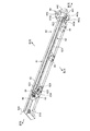
図15は、本発明の実施の形態である商品収納装置20を構成する支持部材70を示す斜視図である。ここで例示する支持部材70は、例えば板金等を屈曲等して形成したものであり、支持基部71と、支持前延部72と、先端締結部73とが一体的に形成されて構成してある。   FIG. 15 is a perspective view showing a support member 70 constituting the commodity storage apparatus 20 according to the embodiment of the present invention. The support member 70 illustrated here is formed by bending a sheet metal or the like, for example, and is configured by integrally forming the support base 71, the support front extending portion 72, and the tip fastening portion 73. is there.

支持基部71は、基端側に形成された平板状部位であり、その下端延部より下方に向けて延在する2つの支持脚部711が設けてある。支持前延部72は、支持基部71の上端延部の中央部分より前方に向けて延在する部位である。この支持前延部72の前後方向の延在長さは、駆動ユニット40における前後長よりも大きいものである。また支持前延部72の両側部721は、上方に向けて屈曲されている。先端締結部73は、支持前延部72の延在端部より上方に向けて延在する部位である。この先端締結部73には、締結用孔部731が形成してある。   The support base 71 is a flat portion formed on the base end side, and is provided with two support legs 711 extending downward from the lower end extension thereof. The support front extension portion 72 is a portion extending forward of the central portion of the upper end extension portion of the support base 71. The extension length of the front support extending portion 72 in the front-rear direction is larger than the front-rear length of the drive unit 40. Further, both side portions 721 of the support front extending portion 72 are bent upward. The front end fastening portion 73 is a portion extending upward from the extension end of the support front extension 72. A fastening hole 731 is formed in the distal end fastening portion 73.

このような支持部材70は、支持脚部711が駆動ユニット40の後方側において該駆動ユニット40とともにコラムケース30の収納部32に収納されることで該コラムケース30に支持されている。   Such a support member 70 is supported by the column case 30 by the support leg 711 being accommodated in the accommodation portion 32 of the column case 30 together with the drive unit 40 on the rear side of the drive unit 40.

また支持部材70は、支持前延部72が後方側より駆動ケース40a,40bの貫通孔40cを貫通するとともに伝達部材44の中空部444を貫通している。そして、支持部材70は、図16に示すように、先端締結部73の前面がベース61の後端締結部613aの後面と接した状態で互いの締結用孔部615,731を貫通する締結部材であるネジNが図示せぬナットと螺合することでベース61に締結してある。   Further, in the support member 70, the support front extending portion 72 penetrates the through holes 40c of the drive cases 40a and 40b from the rear side and penetrates the hollow portion 444 of the transmission member 44. Then, as shown in FIG. 16, the support member 70 is a fastening member which penetrates the fastening holes 615 and 731 in a state where the front surface of the distal end fastening portion 73 is in contact with the rear surface of the rear end fastening portion 613 a of the base 61. The screw N, which is a screw, is fastened to the base 61 by screwing with a nut (not shown).

更に、図には明示しないが、支持部材70の支持前延部72は、売切検知スイッチ64に接続された配線を上面に這わせるようにして該配線を案内している。   Furthermore, although not clearly shown in the figure, the support front extending portion 72 of the support member 70 guides the wiring connected to the sold-out detection switch 64 in such a manner that the wiring extends over the upper surface.

図17は、本発明の実施の形態である商品収納装置20の特徴的な制御系を示すブロック図である。この図17に示すように、商品収納装置20は、払出検出センサS及び商品収納制御部80を備えている。   FIG. 17 is a block diagram showing a characteristic control system of the commodity storage apparatus 20 according to the embodiment of the present invention. As shown in FIG. 17, the product storage device 20 includes a payout detection sensor S and a product storage control unit 80.

払出検出センサSは、例えば光センサ等のようなものであり、商品収納装置20から払い出された商品を検出するものである。この払出検出センサSは、商品収納装置20から払い出された商品を検出した場合には、払出信号を商品収納制御部80に送出するものである。本実施の形態においては、払出検出センサSは、商品取出口15aの近傍に設けてある(図1参照)。   The payout detection sensor S is, for example, an optical sensor or the like, and detects a commodity paid out from the commodity storage device 20. The payout detection sensor S sends a payout signal to the commodity storage control unit 80 when the commodity dispensed from the commodity storage device 20 is detected. In the present embodiment, the payout detection sensor S is provided in the vicinity of the commodity outlet 15a (see FIG. 1).

商品収納制御部80は、メモリ81に記憶されたプログラムやデータに従って商品収納装置20の動作を統括的に制御する制御手段である。この商品収納制御部80は、入力処理部801、出力処理部802、時間計測部803及びモータ駆動処理部804を備えている。   The product storage control unit 80 is a control unit that generally controls the operation of the product storage device 20 in accordance with a program or data stored in the memory 81. The product storage control unit 80 includes an input processing unit 801, an output processing unit 802, a time measuring unit 803, and a motor drive processing unit 804.

入力処理部801は、搬出検知スイッチ43から与えられる搬出ロー信号や搬出ハイ信号、売切検知スイッチ64から与えられる売切ロー信号(商品有り)や売切ハイ信号(商品無し)、更に払出検出センサSから送出された払出信号を入力処理するものである。   The input processing unit 801 detects the delivery low signal and the delivery high signal given from the delivery detection switch 43, the sale low signal (product present) and the sale high signal (no product) given from the sale sell detection switch 64, and the payout detection. The payout signal sent out from the sensor S is subjected to input processing.

ところで、商品収納制御部80と、搬出検知スイッチ43及び売切検知スイッチ64とは、商品収納制御部80に接続された配線を途中で分岐させて一方を搬出検知スイッチ43に、他方を売切検知スイッチ64に接続させるようにしている。つまり、搬出検知スイッチ43と売切検知スイッチ64とを商品収納制御部80に対して並列に接続している。   By the way, the commodity storage control unit 80, the carry-out detection switch 43, and the sold-out detection switch 64 branch the wiring connected to the commodity storage control unit 80 along the way and one is sold out to the carry-out detection switch 43 The detection switch 64 is connected. That is, the carry-out detection switch 43 and the sold-out detection switch 64 are connected in parallel to the commodity storage control unit 80.

また、入力処理部801は、商品収納制御部80の上位機器である自販機制御部90から与えられる指令を入力処理するものである。ここで自販機制御部90は、商品収納装置20が適用された自動販売機の販売動作や商品管理動作を統括的に制御するものである。具体的には、自販機制御部90は、扉体14に設けられた商品選択手段(商品選択ボタン等)が利用者により操作された場合には、該商品選択手段に関連付けられた商品収納装置20に対して電子マネー等の減算処理を行ってから払出指令を与えるものである。   Further, the input processing unit 801 inputs and processes an instruction given from the vending machine control unit 90 which is a high-order device of the commodity storage control unit 80. Here, the vending machine control unit 90 centrally controls the sales operation and the commodity management operation of the vending machine to which the commodity storage device 20 is applied. Specifically, when the item selection means (item selection button etc.) provided on the door 14 is operated by the user, the vending machine control unit 90 controls the item storage device 20 associated with the item selection means. Then, a payout command is given after performing subtraction processing of electronic money or the like.

出力処理部802は、自販機制御部90に対して各種信号を送出するものである。時間計測部803は、時間計測処理を行うものである。モータ駆動処理部804は、モータ41に駆動指令又は駆動停止指令を与えてモータ41を駆動若しくは駆動停止にさせるものである。   The output processing unit 802 sends various signals to the vending machine control unit 90. The time measurement unit 803 performs time measurement processing. The motor drive processing unit 804 gives a drive command or a drive stop command to the motor 41 to drive or stop the motor 41.

以上のような構成を有する商品収納装置20の商品収納制御部80は、待機状態において売切アクチュエータ63が図13に示したように進出姿勢となることで、入力処理部801を通じて売切検知スイッチ64から売切ハイ信号を入力した場合には、当該商品収納装置20のスパイラル50に拘束された商品は売り切れたものとして、出力処理部802を通じて自販機制御部90に売切状態信号を送出する。   The product storage control unit 80 of the product storage device 20 having the above-described configuration operates in the stand-by state, with the sold-out actuator 63 in the advanced position as shown in FIG. When the sold-out high signal is input from 64, it is assumed that the product constrained by the spiral 50 of the product storage device 20 is sold out, and the sold out state signal is sent to the vending machine control unit 90 through the output processing unit 802.

これにより、自販機制御部90は、当該商品収納装置20の商品は売り切れたものとして、該商品収納装置20に関連付けられた商品選択手段の操作を無効化させるとともに、該商品収納装置20に収納された商品が売り切れた旨を図示せぬ売切ランプ等を点灯させて報知する。これによれば、利用者が当該商品収納装置20の商品を選択してしまうことを回避させることができる。   As a result, the vending machine control unit 90 invalidates the operation of the commodity selection means associated with the commodity storage device 20 as the commodity of the commodity storage device 20 is sold out, and is stored in the commodity storage device 20. A not-shown sale sale lamp or the like is turned on to notify that the product has been sold out. According to this, it is possible to prevent the user from selecting a product of the product storage device 20.

一方、待機状態において売切アクチュエータ63が図14に示したように進出姿勢から退行移動することで、入力処理部801を通じて売切検知スイッチ64から売切ロー信号を入力した商品収納制御部80は、スパイラル50の少なくとも最前域のピッチ間には商品が拘束されているので、次のような商品払出制御処理を行う。   On the other hand, the commodity storage control unit 80 receives the sellout low signal from the sellout detection switch 64 through the input processing unit 801 by the saleout actuator 63 moving backward from the advanced position as shown in FIG. 14 in the standby state. Since the product is constrained between the pitches of at least the front area of the spiral 50, the following product delivery control process is performed.

図18は、商品収納装置20の商品収納制御部80が実施する商品払出制御処理の処理内容を示すフローチャートである。   FIG. 18 is a flowchart showing the processing content of the commodity delivery control processing performed by the commodity storage control unit 80 of the commodity storage device 20.

以下においては、かかる商品払出制御処理の処理内容を説明しながら、商品収納装置20の動作について説明する。   In the following, the operation of the product storage device 20 will be described while describing the processing content of the product delivery control process.

この商品払出制御処理において、商品収納制御部80は、入力処理部801を通じて自販機制御部90からの払出指令の入力待ちとなる(ステップS101)。   In the commodity delivery control process, the commodity storage control unit 80 waits for input of a payout instruction from the vending machine control unit 90 through the input processing unit 801 (step S101).

そして、利用者が商品選択手段を通じて当該商品収納装置20の商品を選択するとともに、所定の通信領域に電子マネー記録媒体を翳すことで減算処理が行われることにより、自販機制御部90から払出指令が送出され、これにより入力処理部801を通じて払出指令を入力した場合(ステップS101:Yes)、商品収納制御部80は、モータ駆動処理部804を通じてモータ41に駆動指令を送出する(ステップS102)。これによりモータ41は駆動し、出力ギア42及び伝達部材44は、前方から見た場合に中心軸を中心として時計回りの方向に回転する。つまり、スパイラル50も自身の中心軸回りに回転する。   Then, the user selects a product of the product storage device 20 through the product selection means, and the electronic money recording medium is moved to a predetermined communication area, whereby a subtraction process is performed, whereby the dispensing command from the vending machine control unit 90 When the delivery command is input through the input processing unit 801 (step S101: Yes), the commodity storage control unit 80 sends a drive command to the motor 41 through the motor drive processing unit 804 (step S102). Thereby, the motor 41 is driven, and the output gear 42 and the transmission member 44 rotate clockwise around the central axis when viewed from the front. That is, the spiral 50 also rotates around its own central axis.

このように伝達部材44が出力ギア42とともに前方から見て時計回りの方向に回転すると、待機状態において第2伝達軸部443の第1端面部443aに接していたスライダ後端部622は、該第2伝達軸部443の第3端面部443cに接した後に第2端面部443bと接する。これによりスライダ62は、スライダバネ625の付勢力に抗して前方に向けて移動する。   As described above, when the transmission member 44 rotates clockwise with the output gear 42 as viewed from the front, the slider rear end 622 which has been in contact with the first end face 443a of the second transmission shaft 443 in the standby state is After being in contact with the third end face portion 443 c of the second transmission shaft portion 443, it is in contact with the second end face portion 443 b. As a result, the slider 62 moves forward against the biasing force of the slider spring 625.

スライダ62が前方に向けて移動すると、図19に示すようにスライダ前端部623が売切アクチュエータ63の当接部632の上方に位置し、該売切アクチュエータ63を退行移動した状態に強制的に保持させる。   When the slider 62 moves forward, as shown in FIG. 19, the slider front end portion 623 is positioned above the contact portion 632 of the sell-off actuator 63, and the sell-off actuator 63 is forced to move backward. Hold it.

そして、モータ41の駆動による出力ギア42及び伝達部材44の回転によりスパイラル50が回転し、これによりスパイラル50の各ピッチ間に拘束された商品は前方に向けて搬出され、最前のピッチ間に拘束された商品は前方に向けて払い出される。   Then, the spiral 50 is rotated by the rotation of the output gear 42 and the transmission member 44 by the drive of the motor 41, whereby the product constrained between the pitches of the spiral 50 is carried forward and is constrained between the foremost pitches. The goods that have been purchased are paid out forward.

ところで、上述したように出力ギア42の突部423は、伝達部材44の第1端面部443aよりも前方から見た場合に中心軸を中心として時計回りの方向に僅かに回転した位置に配置されているので、出力ギア42が回転をしていると、搬出検知スイッチ43は次のようになる。すなわち、搬出検知スイッチ43は、搬出接触子が突部423に当接して押圧されることで搬出ハイ信号を送出し、出力ギア42の回転により搬出接触子が突部423から離脱すると待機姿勢となって搬出ロー信号を送出する。   By the way, as described above, the projection 423 of the output gear 42 is disposed at a position slightly rotated in the clockwise direction about the central axis when viewed from the front of the first end face portion 443a of the transmission member 44 Because the output gear 42 is rotating, the carry-out detection switch 43 is as follows. That is, the discharge detection switch 43 sends a discharge high signal when the discharge contact is brought into contact with the protrusion 423 and pressed, and when the discharge contact is separated from the protrusion 423 by the rotation of the output gear 42, And sends out a low signal.

従って、商品収納制御部80は、入力処理部801を通じて搬出検知スイッチ43から搬出ハイ信号を入力した後に搬出ロー信号を入力した場合(ステップS103:Yes,ステップS104:Yes)、すなわち入力処理部801を通じて搬出検知スイッチ43から入力した信号がハイからローに切り換わった場合に、ステップS101の払出指令の入力から予め設定された切換時間が経過したものとして、時間計測部803を通じて予め設定された基準時間の計測を開始する(ステップS105)。   Therefore, when the commodity storage control unit 80 receives the discharge low signal after inputting the discharge high signal from the discharge detection switch 43 through the input processing unit 801 (step S103: Yes, step S104: Yes), that is, the input processing unit 801. When the signal input from the carry-out detection switch 43 switches from high to low, the reference set in advance through the time measuring unit 803 is assumed to have elapsed from the input of the payout command in step S101. The measurement of time is started (step S105).

ここで基準時間は、モータ41に対して駆動停止指令を送出するまでの時間であり、かかる基準時間の計測を開始した時点では、出力ギア42及び伝達部材44は、略一回転しており、第2伝達軸部443の第2端面部443bに摺接していたスライダ後端部622は、第3端面部443cに接することとなる。そのため、スライダ62は、図20に示すように、スライダバネ625に付勢されて後方に向けて移動し、スライダ前端部623は売切アクチュエータ63から離脱する。   Here, the reference time is the time until the drive stop command is sent to the motor 41, and when the measurement of the reference time is started, the output gear 42 and the transmission member 44 make approximately one rotation, The slider rear end portion 622 in sliding contact with the second end surface portion 443b of the second transmission shaft portion 443 is in contact with the third end surface portion 443c. Therefore, as shown in FIG. 20, the slider 62 is biased by the slider spring 625 to move rearward, and the slider front end portion 623 separates from the sell-off actuator 63.

これにより売切アクチュエータ63は、図14に示すように最前域のピッチ間に拘束された商品Wに傾斜延在部633が押圧される場合には進出姿勢から退行移動した姿勢となり、図13に示すように最前域のピッチ間に拘束された商品に傾斜延在部633が押圧されない場合には進出姿勢となる。   As a result, as shown in FIG. 14, the sold-out actuator 63 is in a posture of retreating movement from the advancing posture when the inclined extension portion 633 is pressed by the product W restrained between the pitches of the front region, as shown in FIG. As shown, when the inclined extension portion 633 is not pressed by the product constrained between the pitches of the foremost area, it is in the advanced position.

従って、ステップS105で時間計測部803を通じて基準時間の計測を開始した商品収納制御部80は、基準時間が経過するまでに入力処理部801を通じて売切検知スイッチ64からの売切ハイ信号の入力待ちとなる(ステップS106,ステップS107)。   Accordingly, the commodity storage control unit 80 which has started measuring the reference time through the time measuring unit 803 in step S105 waits for the input of the sold-out high signal from the sold-out detection switch 64 through the input processing unit 801 until the reference time elapses. (Steps S106 and S107).

この結果、基準時間が経過するまでに入力処理部801を通じて売切ハイ信号を入力した場合(ステップS106:No,ステップS107:Yes)、商品収納制御部80は、出力処理部802を通じて自販機制御部90に売切状態信号を送出し(ステップS108)、その後に基準時間が経過した時点でモータ駆動処理部804を通じてモータ41に駆動停止指令を送出して(ステップS106:Yes,ステップS109)、モータ41の駆動を停止させる。   As a result, when the sale processing high signal is input through the input processing unit 801 before the reference time elapses (step S106: No, step S107: Yes), the commodity storage control unit 80 controls the vending machine control unit through the output processing unit 802. A sellout status signal is sent out to 90 (step S108), and a drive stop command is sent to the motor 41 through the motor drive processing unit 804 when the reference time elapses thereafter (step S106: Yes, step S109). Stop the drive of 41.

このように商品収納制御部80から売切状態信号を送出された自販機制御部90では、当該商品収納装置20の商品は売り切れたものとして、該商品収納装置20に関連付けられた商品選択手段の操作を無効化させるとともに、該商品収納装置20に収納された商品が売り切れた旨を図示せぬ売切ランプ等を点灯させて報知する。   Thus, in the vending machine control unit 90 to which the sold condition signal is sent from the product storage control unit 80, the product of the product storage device 20 is regarded as sold out, and the operation of the product selection means associated with the product storage device 20 is performed. And informing the user of the fact that the product stored in the product storage device 20 has been sold out by turning on a sale sale lamp or the like (not shown).

また、基準時間の経過後にモータ41を駆動停止にさせることで、伝達部材44は中心軸回りに一回転し、第2伝達軸部443においては第1端面部443aが待機状態と同様に下方に位置する。   In addition, by stopping the driving of the motor 41 after the reference time has elapsed, the transmission member 44 makes one rotation around the central axis, and in the second transmission shaft portion 443 the first end surface portion 443a goes downward similarly to the standby state. To position.

一方、売切ハイ信号を入力することなく基準時間を経過した場合(ステップS106:Yes,ステップS107:No)、商品収納制御部80は、モータ駆動処理部804を通じてモータ41に駆動停止指令を送出して(ステップS109)、モータ41の駆動を停止させる。   On the other hand, when the reference time has elapsed without inputting the sold-out high signal (step S106: Yes, step S107: No), the commodity storage control unit 80 sends a drive stop command to the motor 41 through the motor drive processing unit 804. Then, the driving of the motor 41 is stopped (step S109).

ところで、スパイラル50から商品が払い出された場合、この払い出された商品は、搬送トレイ12に受容され、搬送トレイ12により商品取出口15aの近傍まで搬送される。かかる商品は、その後に商品取出口15aを通じて取り出し可能な状態となる。   By the way, when a product is paid out from the spiral 50, the paid-out product is received by the transport tray 12, and is transported by the transport tray 12 to the vicinity of the product outlet 15a. Such a product is then ready for removal through the product outlet 15a.

上記ステップS109でモータ41に駆動停止指令を送出した商品収納制御部80は、時間計測部803を通じて設定時間の計測を開始し(ステップS110)、この設定時間が経過するまでに払出検出センサSからの払出信号の入力待ちとなる(ステップS111,ステップS112)。   The commodity storage control unit 80 which has sent the drive stop command to the motor 41 at step S109 starts measurement of the set time through the time measurement unit 803 (step S110), and from the payout detection sensor S until this set time elapses. Waiting for the input of the payout signal (steps S111 and S112).

そして、設定時間が経過するまでに入力処理部801を通じて払出信号を入力した場合(ステップS111:Yes,ステップS112:No)、商品収納制御部80は、出力処理部802を通じて自販機制御部90に払出完了信号を送出し(ステップS113)、その後に手順をリターンさせて今回の処理を終了する。これによれば、自販機制御部90に払出指令に対する応答として商品の払い出しが完了した旨を伝達することができる。   Then, when the payout signal is input through the input processing unit 801 before the set time elapses (step S111: Yes, step S112: No), the commodity storage control unit 80 pays out to the vending machine control unit 90 through the output processing unit 802. A completion signal is sent out (step S113), and then the procedure is returned to end the current process. According to this, it is possible to notify the vending machine control unit 90 that the delivery of the product is completed as a response to the dispensing command.

これによれば、払出指令を送出した自販機制御部90に対して商品の払い出しを完了した旨を通知することができ、自販機制御部90において商品数の減算処理を実施することができる。   According to this, it is possible to notify the vending machine control unit 90 which has sent out the dispensing command that the dispensing of the product is completed, and the vending machine control unit 90 can carry out subtraction processing of the number of products.

一方、払出信号を入力することなく設定時間が経過した場合(ステップS111:No,ステップS112:Yes)、商品収納制御部80は、モータ駆動処理部804を通じてモータ41に駆動指令を送出するステップS102〜ステップS110の処理を実施する再試行処理を行う。   On the other hand, when the set time has elapsed without inputting the payout signal (Step S111: No, Step S112: Yes), the commodity storage control unit 80 sends a drive command to the motor 41 through the motor drive processing unit 804. ~ Perform a retry process of performing the process of step S110.

これによれば、モータ41を再度駆動させて払出検出センサSにより商品が検出されるまでスパイラル50を回転させることができる。   According to this, it is possible to rotate the spiral 50 until the motor 41 is driven again and the commodity is detected by the payout detection sensor S.

以上説明したように本発明の実施の形態である商品収納装置20においては、支持前延部72が駆動ケース40a,40bの貫通孔40c及び伝達部材44の中空部444を貫通する態様で支持基部71の支持脚部711がコラムケース30の収納部32に収納されることで該コラムケース30に支持された支持部材70が、先端締結部73がベースユニット60を構成するベース61の後端締結部613aにネジN等で締結されている。これによりベース61は、ベース前端部612がコラムケース30に支持され、かつベース後端部613が上記支持部材70により支持される。よって、上記商品収納装置20によれば、ベース61がスパイラル50の回転の影響を受ける虞れがなく、該スパイラル50により変形等してしまうことを抑制することができる。   As described above, in the product storage device 20 according to the embodiment of the present invention, the support base extension portion 72 penetrates the through holes 40 c of the drive cases 40 a and 40 b and the hollow portion 444 of the transmission member 44. A support member 70 supported by the column case 30 is housed in the storage portion 32 of the column case 30 when the support leg portion 711 of 71 is housed in the rear end of the base 61 of which the front end fastening portion 73 constitutes the base unit 60. It is fastened to the portion 613a with a screw N or the like. Thereby, the base front end portion 612 of the base 61 is supported by the column case 30, and the base rear end portion 613 is supported by the support member 70. Therefore, according to the commodity storage device 20, there is no possibility that the base 61 is affected by the rotation of the spiral 50, and deformation or the like due to the spiral 50 can be suppressed.

また上記商品収納装置20によれば、支持部材70の支持前延部72が売切検知スイッチ64に接続された配線を上面に這わせるようにして該配線を案内しているので、売切検知スイッチ64に接続された配線を商品収納装置20の前方域で這わせることなく後方側に向けて這わせることができる。よって、自動販売機の利用者等に該配線を見せることがなく、美感性を向上させることができる。しかも、配線を支持前延部72の上面に這わせるようにしているので、該配線が回転する伝達部材44と接する虞れがなく、配線が損傷等してしまうことを防止することができる。   Further, according to the product storage device 20, since the support front extending portion 72 of the support member 70 guides the wiring by making the wiring connected to the selling ability detection switch 64 pass on the upper surface, the selling ability detection is performed. The wiring connected to the switch 64 can be wound backward without being wound in the front area of the product storage device 20. Therefore, the aesthetics can be improved without showing the wiring or the like to the user of the vending machine. In addition, since the wiring is laid on the upper surface of the supporting front extending portion 72, there is no possibility that the wiring comes in contact with the rotating transmission member 44, and the wiring can be prevented from being damaged or the like.

また上記商品収納装置20によれば、ベース61のベース後端部613における上方支持片613b、右方支持片613c及び左方支持片613dのそれぞれが伝達部材44における第2伝達軸部443の外周面に対向しているので、ベース61にスパイラル50の各ピッチ間に拘束される商品の荷重が作用する場合に、上方支持片613b、右方支持片613c及び左方支持片613dの少なくとも1つが第2伝達軸部443の外周面に接することで、ベース61が変形等してしまうことを抑制することができる。   Further, according to the product storage device 20, each of the upper support piece 613b, the right support piece 613c and the left support piece 613d at the base rear end 613 of the base 61 is the outer periphery of the second transmission shaft 443 in the transmission member 44. Since it faces the surface, at least one of the upper support piece 613b, the right side support piece 613c, and the left side support piece 613d functions when a load of a product constrained between the pitches of the spiral 50 acts on the base 61. By contacting the outer peripheral surface of the second transmission shaft portion 443, deformation or the like of the base 61 can be suppressed.

また上記商品収納装置20においては、スライダ62のスライダ後端部622が伝達部材44の第2伝達軸部443の前端面(第1端面部443a、第2端面部443b及び第3端面部443c)に摺接することで、スライダ62が前方に移動する場合には、売切アクチュエータ63を退行移動した状態に強制的に保持する。一方、スライダ62が後方に移動する場合には、売切アクチュエータ63を強制的に退行移動させることを解除する。   Further, in the product storage device 20, the slider rear end portion 622 of the slider 62 is a front end surface of the second transmission shaft portion 443 of the transmission member 44 (a first end surface portion 443a, a second end surface portion 443b and a third end surface portion 443c) By sliding contact with the slider 62, when the slider 62 moves forward, the sell-off actuator 63 is forcibly held in the retreated state. On the other hand, when the slider 62 is moved backward, the forced sale movement of the sell-off actuator 63 is canceled.

つまり、伝達部材44の第2伝達軸部443及びスライダ62は、払出指令が与えられてから切換時間が経過するまでは、売切アクチュエータ63を退行移動した状態に強制的に保持して売切検知スイッチ64による検知を無効化させる一方、切換時間が経過した場合には、売切アクチュエータ63を強制的に退行移動させることを解除して売切検知スイッチ64による検知を有効化させる規制手段を構成している。   That is, the second transmission shaft portion 443 of the transmission member 44 and the slider 62 forcibly hold the sold-out actuator 63 in a retracted state until the switching time elapses from the time when the dispensing command is given, and the sold-out The restriction means is configured to cancel the forced withdrawal movement of the sold-out actuator 63 and to enable the detection by the sold-out detection switch 64 when the detection by the detection switch 64 is invalidated while the switching time has elapsed. Configured.

そして、商品収納装置20によれば、払出指令が与えられてから切換時間が経過するまでは売切検知スイッチ64による検知を無効化させる一方、切換時間が経過した場合には売切検知スイッチ64による検知を有効化させることにより、払出指令が与えられてから切換時間が経過するまでは搬出検知スイッチ43からの信号を入力し、切換時間の経過後に売切検知スイッチ64からの信号を入力するようにできる。この結果、上述したように搬出検知スイッチ43と売切検知スイッチ64とを商品収納制御部80に対して並列に接続させることができる。従って、配線の低減化を図ることができる。これにより製造コストの低減化を図ることができる。   Then, according to the product storage device 20, while the detection by the sold-out detection switch 64 is made invalid until the switching time elapses after the delivery instruction is given, the sold-out detection switch 64 when the switching time has elapsed. The signal from the carry-out detection switch 43 is input until the switching time elapses after the discharge instruction is given by enabling the detection by the CPU, and the signal from the sellout detection switch 64 is input after the switching time elapses. It can be done. As a result, as described above, the carry-out detection switch 43 and the sold-out detection switch 64 can be connected in parallel to the commodity storage control unit 80. Therefore, the wiring can be reduced. Thus, the manufacturing cost can be reduced.

このようにスライダ62が前方に移動することにより売切アクチュエータ63を退行移動した状態に強制的に保持させるので、上記商品収納装置20によれば、該売切アクチュエータ63の傾斜延在部633をベース61の上面から退避させることができ、回転するスパイラル50により前方に搬出される商品の姿勢を売切アクチュエータ63により乱してしまうことを回避することができる。   Thus, the slider 62 moves forward to forcibly hold the sell-off actuator 63 in the retreated state. Therefore, according to the product storage device 20, the inclined extension portion 633 of the sell-off actuator 63 is It is possible to retract from the upper surface of the base 61, and it is possible to avoid disturbing the attitude of the product carried forward by the rotating spiral 50 by the sell-off actuator 63.

また上記商品収納装置20においては、商品収納制御部80が、上記商品払出制御処理において、売切検知スイッチ64が商品有りと検知する状態で払出指令が与えられた場合にモータ41を駆動させてスパイラル50を回転させた結果払出検出センサSにより商品が検出されないときには、モータ41を再度駆動させて払出検出センサSにより商品が検出されるまでスパイラル50を回転させる再試行処理を行うので、次のような作用効果を奏する。すなわち、スパイラル50の最前のピッチ間には商品が拘束されずに最前から2番目や3番目のピッチ間に商品が拘束されるいわゆる「歯抜け」状態で商品が収納されている場合において、一旦払出指令が与えられれば、商品が払い出されるまでスパイラル50を回転させることができ、これにより、売切検知スイッチ64が商品有りと検知する状態で払出指令が与えられた場合には、商品の払い出しを確実に行って利用者が不測の不利益を被ることを防止することができる。特に、電子マネー決済のように払出指令が商品収納装置20に与えられるときには既に減算処理が行われている場合に有用である。   Further, in the product storage device 20, the product storage control unit 80 drives the motor 41 when a payout command is given in a state where the sold-out detection switch 64 detects that the product is present in the product payout control process. When no product is detected by the payout detection sensor S as a result of rotating the spiral 50, the motor 41 is driven again, and retry processing is performed to rotate the spiral 50 until the commodity is detected by the payout detection sensor S. It produces the same function and effect. That is, in the case where the product is stored in a so-called "tooth loss" state in which the product is restrained between the foremost second and third pitches without being restrained between the foremost pitches of the spiral 50. If a dispensing command is given, the spiral 50 can be rotated until the product is dispensed, whereby if the dispensing command is given in a state where the sold-out detection switch 64 detects that the product is present, the dispensing of the product To prevent the user from suffering unforeseen disadvantages. In particular, when a payout command is given to the commodity storage apparatus 20 as in the case of electronic money settlement, it is useful when subtraction processing has already been performed.

以上、本発明の好適な実施の形態について説明したが、本発明はこれに限定されるものではなく、種々の変更を行うことができる。   The preferred embodiment of the present invention has been described above, but the present invention is not limited to this, and various modifications can be made.

上述した実施の形態では、払出指令が与えられてから切換時間が経過するまではスライダ62を前方に移動させて売切検知スイッチ64による検知を無効化し、切換時間の経過後にスライダ62を後方に移動させて売切検知スイッチ64による検知を有効化させていたが、本発明においては、上述したスライダ62を用いずに、搬出検知手段及び売切検知手段と、制御手段との間にリレー(継電器)を用いて払出指令が与えられてから切換時間が経過するまでは売切検知手段による検知を無効化させ、切換時間の経過後に売切検知手段による検知を有効化させてもよい。この構造によっても配線の低減化を図ることができる。   In the embodiment described above, the slider 62 is moved forward until the switching time elapses after the dispensing command is given, and the detection by the sellout detection switch 64 is invalidated, and the slider 62 is moved backward after the switching time elapses. The detection of the sold-out detection switch 64 is moved to enable detection by the sold-out detection switch 64. However, in the present invention, the relay 62 is interposed between the unloading detection unit and the sold-out detection unit and the control unit without using the slider 62 described above. The detection by the sold-out detecting means may be invalidated until the switching time elapses after the delivery instruction is given using the relay), and the detection by the sold-out detecting means may be validated after the switching time has elapsed. Wiring can be reduced also by this structure.

上述した実施の形態では、売切アクチュエータ63が進出姿勢、あるいは進出姿勢から退行移動することで商品の有無を検知するようにしていたが、本発明においては、商品の有無については例えば光センサ等を用いて検知するようにしてもよい。   In the above-described embodiment, the presence / absence of the product is detected by moving back and forth from the advancing posture or the advancing posture with the sold-out actuator 63, but in the present invention, for example, an optical sensor It may be detected using

1 本体キャビネット
2 商品収容庫
10 商品ラック
10a ラック基体
20 商品収納装置
30 コラムケース
40 駆動ユニット
41 モータ(駆動源)
42 出力ギア
43 搬出検知スイッチ(搬出検知手段)
44 伝達部材
441 伝達基部
442 第1伝達軸部
443 第2伝達軸部
444 中空部
50 スパイラル
60 ベースユニット
61 ベース
62 スライダ
63 売切アクチュエータ
64 売切検知スイッチ(売切検出手段)
70 支持部材
71 支持基部
72 支持前延部
73 先端締結部
80 商品収納制御部(制御手段)
81 メモリ
801 入力処理部
802 出力処理部
803 時間計測部
804 モータ駆動処理部
S 払出検出センサ(払出検出手段)
1 Main cabinet 2 Merchandise storage 10 Merchandise rack 10a Rack base 20 Merchandise storage device 30 Column case 40 Drive unit 41 Motor (drive source)
42 Output gear 43 Ejection detection switch (Ejection detection means)
Reference Signs List 44 transmission member 441 transmission base 442 first transmission shaft portion 443 second transmission shaft portion 444 hollow portion 50 spiral 60 base unit 61 base 62 slider 63 sold-out actuator 64 sold-out detection switch (sold-out detection means)
Reference Signs List 70 support member 71 support base 72 support front extension portion 73 tip fastening portion 80 product storage control portion (control means)
81 Memory 801 Input Processing Unit 802 Output Processing Unit 803 Time Measurement Unit 804 Motor Drive Processing Unit S Payout Detection Sensor (Discharge Detection Means)

Claims (3)

前後方向に沿って螺旋状に巻回される態様で構成され、かつ伝達機構を介して駆動源より駆動力が伝達された場合に中心軸回りに回転するスパイラルを備え、
払出指令に応じて前記スパイラルを回転させることにより該スパイラルのピッチ間に拘束された商品を漸次前方に向けて搬出して最前のピッチ間の商品を払い出す商品収納装置であって、
前記スパイラルにおける最前域のいずれかのピッチ間の商品の有無を検知する売切検知手段と、
前記スパイラルから払い出された商品を検出する払出検出手段と、
前記売切検知手段が商品有りと検知する状態で前記払出指令が与えられた場合に、前記駆動源を駆動させて前記スパイラルを回転させた結果前記払出検出手段により商品が検出されないときには、前記駆動源を再度駆動させて前記払出検出手段により商品が検出されるまで前記スパイラルを回転させる再試行処理を行う制御手段と
を備えたことを特徴とする商品収納装置。
It is configured in a manner of being spirally wound along the front-rear direction, and includes a spiral that rotates around a central axis when a driving force is transmitted from a drive source via a transmission mechanism,
A commodity storage device for delivering a product between the foremost pitches by discharging the product constrained between the pitches of the spirals gradually forward by rotating the spiral according to a dispensing command,
Selling-out detection means for detecting the presence or absence of a product between any pitches in the front area of the spiral;
A payout detection unit that detects a commodity paid out from the spiral;
When the delivery instruction is given in a state where the sold-out detection means detects that there is a product, the drive is driven to rotate the spiral, and as a result the delivery detection means does not detect a product. And a control unit which performs a retry process of rotating the spiral until the product is detected by driving the source again and the delivery detecting unit detects the product.
前記制御手段は、前記売切検知手段が商品無しと検知する場合には、所定の上位機器に対して売切状態である旨を送出することを特徴とする請求項1に記載の商品収納装置。   The product storage device according to claim 1, wherein the control means sends out a sold out state to a predetermined higher-level device when the sold out detecting means detects that there is no product. . 前記スパイラルの内部を貫通する態様で前後方向に沿って延在し、かつ上面に商品を載置させるベースと、
前記ベースの上方域に進退移動する態様で該ベースに揺動可能に配設され、かつ常態においては付勢手段に付勢されて進出姿勢となる一方、最前域のいずれかのピッチ間の商品に押圧される場合には前記付勢手段の付勢力に抗して前記進出姿勢から退行移動する売切アクチュエータと
を備え、
前記売切検知手段は、前記売切アクチュエータが前記進出姿勢から退行移動する場合には商品有りと検知する一方、前記売切アクチュエータが進出姿勢となる場合には商品無しと検知することを特徴とする請求項1又は請求項2に記載の商品収納装置。
A base extending along the front-rear direction in a manner to penetrate the inside of the spiral and having a commodity placed on the upper surface;
It is swingably disposed on the base in an advancing and retreating manner in the upper area of the base, and is normally urged by the biasing means to be in an advancing posture, and a product between any pitch in the foremost area And a sell-off actuator that moves backward from the advancing position against the biasing force of the biasing means, and
The sold-out detecting unit detects that the product is present when the sold-out actuator moves backward from the advanced position, and detects that the product is absent when the sold-out actuator is in the advanced position. The goods storage apparatus according to claim 1 or 2.
JP2015014458A 2015-01-28 2015-01-28 Product storage device Active JP6515552B2 (en)

Priority Applications (2)

Application Number Priority Date Filing Date Title
JP2015014458A JP6515552B2 (en) 2015-01-28 2015-01-28 Product storage device
CN201511020230.5A CN105825588B (en) 2015-01-28 2015-12-30 Commodity storage device

Applications Claiming Priority (1)

Application Number Priority Date Filing Date Title
JP2015014458A JP6515552B2 (en) 2015-01-28 2015-01-28 Product storage device

Publications (2)

Publication Number Publication Date
JP2016139315A JP2016139315A (en) 2016-08-04
JP6515552B2 true JP6515552B2 (en) 2019-05-22

Family

ID=56514946

Family Applications (1)

Application Number Title Priority Date Filing Date
JP2015014458A Active JP6515552B2 (en) 2015-01-28 2015-01-28 Product storage device

Country Status (2)

Country Link
JP (1) JP6515552B2 (en)
CN (1) CN105825588B (en)

Families Citing this family (8)

* Cited by examiner, † Cited by third party
Publication number Priority date Publication date Assignee Title
KR102114945B1 (en) * 2018-08-31 2020-05-26 롯데알미늄 주식회사 Automatic vending machine for ice pouch and Method for controling the same
CN112150705B (en) * 2019-06-28 2022-05-31 富士电机株式会社 Commodity storage device
JP7310363B2 (en) * 2019-06-28 2023-07-19 富士電機株式会社 Product storage device
JP6821750B1 (en) * 2019-07-12 2021-01-27 株式会社バンダイ Goods supply device and goods supply system
JP6903106B2 (en) * 2019-08-30 2021-07-14 株式会社バンダイ Goods supply equipment, goods supply system and payment system
JP2021089690A (en) * 2019-12-06 2021-06-10 富士電機株式会社 Commodity storage device
JP7528708B2 (en) 2020-10-14 2024-08-06 富士電機株式会社 Product storage device
JP7528707B2 (en) 2020-10-14 2024-08-06 富士電機株式会社 Product storage device

Family Cites Families (9)

* Cited by examiner, † Cited by third party
Publication number Priority date Publication date Assignee Title
JPH0581533A (en) * 1991-09-04 1993-04-02 Sanyo Electric Co Ltd Spiral type automatic vending machine
US5303844A (en) * 1992-04-28 1994-04-19 Keyosk Corporation Automated apparatus, system and method for reliably vending articles of increased value
JP3820837B2 (en) * 2000-02-29 2006-09-13 富士電機リテイルシステムズ株式会社 Vending machine control equipment
IT251040Y1 (en) * 2000-08-10 2003-11-04 Fas International Spa PERFECTED DEVICE FOR THE EXPULSION OF A PRODUCT FROM AN AUTOMATIC DISTRIBUTOR.
JP2007034660A (en) * 2005-07-27 2007-02-08 Fuji Electric Retail Systems Co Ltd Vending machine
JP2010102533A (en) * 2008-10-24 2010-05-06 Panasonic Corp Commodity sending-off device and vending machine
JP5742397B2 (en) * 2011-04-05 2015-07-01 富士電機株式会社 vending machine
CN203455895U (en) * 2013-08-30 2014-02-26 富士电机株式会社 Commodity storage device
CN203455894U (en) * 2013-08-30 2014-02-26 富士电机株式会社 Commodity storage device

Also Published As

Publication number Publication date
CN105825588B (en) 2020-02-21
JP2016139315A (en) 2016-08-04
CN105825588A (en) 2016-08-03

Similar Documents

Publication Publication Date Title
JP6515552B2 (en) Product storage device
JP6459560B2 (en) Product storage device
JP6443459B2 (en) Product storage device
CN107545644B (en) Commodity storage device
JP6528639B2 (en) Product storage device
WO2015105150A1 (en) Product delivery device
JP6209970B2 (en) Product carrying device
JP2010282588A (en) Vending machine
JP6728623B2 (en) Product storage device
JP6221755B2 (en) Product carrying device
JP6295755B2 (en) Product dispensing device
JP6610750B2 (en) Product dispensing device
JP6341297B2 (en) Product dispensing device
WO2017022441A1 (en) Product storage device and automatic vending machine
JP6365683B2 (en) Product dispensing device
JP7528708B2 (en) Product storage device
JP6485115B2 (en) Product dispensing device
JP2022064516A (en) Product storage device
JP2021112351A (en) Product storage device
JP2023093240A (en) Anti-theft shutter mechanism for vending machine
JPH113463A (en) Automatic vending machine

Legal Events

Date Code Title Description
A621 Written request for application examination

Free format text: JAPANESE INTERMEDIATE CODE: A621

Effective date: 20171114

A131 Notification of reasons for refusal

Free format text: JAPANESE INTERMEDIATE CODE: A131

Effective date: 20180904

A977 Report on retrieval

Free format text: JAPANESE INTERMEDIATE CODE: A971007

Effective date: 20180831

TRDD Decision of grant or rejection written
A01 Written decision to grant a patent or to grant a registration (utility model)

Free format text: JAPANESE INTERMEDIATE CODE: A01

Effective date: 20190319

A61 First payment of annual fees (during grant procedure)

Free format text: JAPANESE INTERMEDIATE CODE: A61

Effective date: 20190401

R150 Certificate of patent or registration of utility model

Ref document number: 6515552

Country of ref document: JP

Free format text: JAPANESE INTERMEDIATE CODE: R150

R250 Receipt of annual fees

Free format text: JAPANESE INTERMEDIATE CODE: R250

R250 Receipt of annual fees

Free format text: JAPANESE INTERMEDIATE CODE: R250

R250 Receipt of annual fees

Free format text: JAPANESE INTERMEDIATE CODE: R250

R250 Receipt of annual fees

Free format text: JAPANESE INTERMEDIATE CODE: R250