JP6514006B2 - Farm work machine - Google Patents
Farm work machine Download PDFInfo
- Publication number
- JP6514006B2 JP6514006B2 JP2015075522A JP2015075522A JP6514006B2 JP 6514006 B2 JP6514006 B2 JP 6514006B2 JP 2015075522 A JP2015075522 A JP 2015075522A JP 2015075522 A JP2015075522 A JP 2015075522A JP 6514006 B2 JP6514006 B2 JP 6514006B2
- Authority
- JP
- Japan
- Prior art keywords
- clutch
- reverse
- high speed
- transmission
- speed
- Prior art date
- Legal status (The legal status is an assumption and is not a legal conclusion. Google has not performed a legal analysis and makes no representation as to the accuracy of the status listed.)
- Active
Links
Images


Landscapes
- Arrangement And Mounting Of Devices That Control Transmission Of Motive Force (AREA)
- Arrangement Or Mounting Of Control Devices For Change-Speed Gearing (AREA)
- Mechanical Control Devices (AREA)
Description
この発明は、低速側クラッチと高速側クラッチとが択一的に接続される農作業機に関する。 The present invention relates to a farm work machine in which a low speed clutch and a high speed clutch are alternatively connected.
走行部に原動機からの動力を伝動する伝動装置と、該伝動装置における走行部への動力伝動経路の途中に配置された変速機構と、該伝動装置における走行部への動力伝動経路の途中における変速機構の伝動下流側又は上流側に配設されて高速動力を断続する高速側クラッチ及び低速動力を断続する低速側クラッチと、前記高速側クラッチと低速側クラッチを択一的に接続させる断続操作具とを備えた農作業機が公知になっている(例えば、特許文献1,2を参照)。 A transmission for transmitting power from a prime mover to a traveling unit, a transmission mechanism disposed in the middle of a power transmission path to the traveling unit in the transmission, and transmission in the middle of a power transmission path to the traveling unit in the transmission A high speed side clutch disposed on the transmission downstream side or upstream side of the mechanism to interrupt the high speed power, a low speed side clutch for interrupting the low speed power, and an on / off operation tool selectively connecting the high speed clutch and the low speed clutch An agricultural work machine provided with the prior art is known (see, for example, Patent Documents 1 and 2).
上記文献の農作業機では、通常、変速レバーによって、変速機構の切換操作を行うが、高速側クラッチが接続されて高速動力が伝動される状態においては、変速機構の後進への切換は規制した方が、走行時の安定性という観点から望ましい。そして、このような規制を行う場合、変速レバーによる変速機構の後進への切換を規制する規制部材を設け、この規制部材の作用・非作用を切換える操作を行うことが一般的に考えられる。 In the farm work machine of the above-mentioned document, usually the switching operation of the transmission mechanism is performed by the shift lever, but in the state where the high speed side clutch is connected and the high speed power is transmitted, the switching of the transmission mechanism to reverse is restricted. Is desirable from the viewpoint of stability during traveling. When performing such regulation, it is generally conceivable to provide a regulating member for regulating the switching of the transmission mechanism to the reverse direction by the shift lever, and to perform an operation of switching the operation / non-operation of the regulation member.
しかし、該構成によれば、規制部材の作用状態から非作用状態への切換を忘れた状態で、低速側クラッチを接続させた場合、低速動力が伝動されているにもかかわらず、上記規制部材による変速機構の後進規制が意図せずに行われる一方で、既に後進に切換えている場合には上記規制が行えず、問題がある他、規制部材を操作するための部材も別途必要になり、コスト高になる。 However, according to the configuration, when the low speed side clutch is connected in a state where the switching from the operating state to the non-operating state of the restricting member is forgotten, the restricting member is transmitted despite the low speed power being transmitted. While the reverse control of the speed change mechanism is performed unintentionally, the above restriction can not be performed when switching to reverse, and there is a problem, and a member for operating the restricting member is also required separately. It becomes expensive.
本発明は、低速側クラッチ及び高速側クラッチの断続切換と、後進規制の作用・非作用の切換とを、適切に行うことが容易で、且つコストも安価な農作業機を提供することを課題とする。 It is an object of the present invention to provide an agricultural work machine which can easily perform the intermittent switching of the low speed clutch and the high speed clutch and the switching between the operation and non-operation of the reverse regulation properly and at low cost. Do.
上記課題を解決するため、走行部7に原動機2からの動力を伝動する伝動装置と、該伝動装置における走行部7への動力伝動経路の途中に配置され且つ前進時複数段及び後進時一段の変速を行う変速機構12と、該伝動装置における走行部7への動力伝動経路の途中における変速機構12の伝動下流側又は上流側に配設されて高速動力を断続する高速側クラッチ及び低速動力を断続する低速側クラッチと、前記変速機構12の変速操作を行う変速レバー14と、前記高速側クラッチと低速側クラッチを択一的に接続させる断続操作具13と、前記変速レバー14による上記変速機構12の後進への切換操作である後進操作を規制する後進側規制部材38とを備え、高速側クラッチを接続させた場合には、前記後進側規制部材38によって、変速レバー14の後進操作が規制されるとともに、変速レバー14を後進操作させた場合には、前記後進側規制部材38によって、高速側クラッチの接続が規制されるように、該後進側規制部材38を、連係機構43を介して、前記高速側クラッチに機械的に連係させたことを特徴としている。
In order to solve the above problems, there is provided a transmission for transmitting the power from the
前記後進側規制部材38は、高速側クラッチの断続によって揺動されるように支持された丸棒状の規制アームであり、上記規制アーム38に接当する接当部44を、該変速レバー14の中途部に一体的に設け、前記高速側クラッチを接続させた場合には、規制アーム38と接当部44との接当によって、前記変速レバー14の後進操作が規制される一方で、前記変速レバー14を後進操作した場合には、規制アーム38と接当部44との接当によって、前記高速側クラッチの接続が規制されるものとしてもよい。
The reverse-
高速側クラッチを接続させた場合には、後進側規制部材によって、変速レバーの後進操作が規制されるとともに、変速レバーを後進操作させた場合には、前記後進側規制部材によって、高速側クラッチの接続が規制されるように、該後進側規制部材を、連係機構を介して、前記高速側クラッチに機械的に連係させたので、低速側クラッチ及び高速側クラッチの断続切換と、後進規制の作用・非作用の切換とを、適切に行うことが容易であり、誤操作を効率的に防止するとともに、後進側規制部材を操作する部材を別途設ける必要がなく、コスト安になる他、後進側規制部材の作用・非作用は、低速側クラッチに関係無く、高速側クラッチによってのみ切換えられるため、低速側クラッチを接続させている状態で、後進操作が規制されることが防止される。 When the high-speed clutch is engaged, the reverse operation of the shift lever is restricted by the reverse-side regulating member, and when the shift lever is operated reversely, the high-speed clutch is actuated by the reverse-side regulating member. Since the reverse side regulating member is mechanically linked to the high speed side clutch via the link mechanism so that the connection is restricted, the operation of the low speed side clutch and the high speed side clutch and the action of the reverse direction restriction -It is easy to appropriately perform the non-operational switching, prevent erroneous operation efficiently, and it is not necessary to separately provide a member for operating the reverse side regulating member, which reduces the cost and also prevents the reverse side regulation. Since the action / non-action of the member is switched only by the high-speed clutch regardless of the low-speed clutch, the reverse operation is restricted while the low-speed clutch is engaged. It is locked.
前記後進側規制部材は、高速側クラッチの断続によって揺動されるように支持された丸棒状の規制アームであり、上記規制アームに接当する接当部を、該変速レバーの中途部に一体的に設け、前記高速側クラッチを接続させた場合には、規制アームと接当部との接当によって、前記変速レバーの後進操作が規制される一方で、前記変速レバーを後進操作した場合には、規制アームと接当部との接当によって、前記高速側クラッチの接続が規制されるものによれば、シンプルで安価な構成で、上記した規制内容を実現できる。 The reverse side regulation member is a round bar-like regulation arm supported so as to be swung by engagement and disengagement of the high speed clutch, and an abutment portion abutting on the regulation arm is integrated with a middle portion of the shift lever. When the high speed clutch is engaged, the reverse operation of the shift lever is restricted by the contact between the restricting arm and the contact portion, while the reverse operation of the shift lever is performed. According to the invention in which the connection of the high-speed clutch is restricted by the contact between the restriction arm and the contact part, the above-mentioned restriction contents can be realized with a simple and inexpensive configuration.
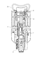
図1,図2は、本発明の農作業機を適用した歩行型管理機の側面図及び平面図である。図示する歩行型管理機は、前後方向に延びる機体フレーム1と、該機体フレーム1上に搭載されたエンジン(原動機)2と、該エンジン2の側部に設置された前後方向の伝動ケース3と、該伝動ケース3の後端側から前方斜め下方に延びるミッションケース4と、該伝動ケース3の後端側から後方斜め下方に延びるロータリケース6と、前記ミッションケース4の下端部に回転駆動可能に支持された左右一対の車輪7と、前記ロータリケースの下端部に設置された左右方向の耕耘ロータリ8と、機体フレーム1の後端側から後方斜め上方に向かって一体的に延設されたハンドルフレーム(操作ボックス)9と、該ハンドルフレーム9から後方斜め上方の突出形成され且つ平面視でハンドルフレーム9と共にループ状をなす操向ハンドル11とを備えている。
1 and 2 are a side view and a plan view of a walking type control machine to which a farm work machine of the present invention is applied. The walking type control machine illustrated includes an airframe frame 1 extending in the front-rear direction, an engine (motor) 2 mounted on the airframe frame 1, and a
エンジン2で発生した動力は、伝動ケース3内の伝動ベルト(図示しない)を介して、ミッションケース4内の走行変速機構(変速機構)12(図5,6参照)に伝動される。この伝動ベルトは左右一対で設けられ、一方の伝動ベルトは、その伝動比によって、高速の動力を、走行変速機構12に伝動する高速側伝動ベルトであり、他方の伝動ベルトは、その伝動比によって、低速の動力を、走行変速機構12に伝動する低速側伝動ベルトである。
The power generated by the
各伝動ベルトには、テンションを付与するプーリからなる構成され且つ走行変速機構12にベルト伝動される動力を断続するクラッチが設置されている。高速伝動ベルト側のクラッチは、上記した高速動力を断続する高速側クラッチであり、低速伝動ベルト側のクラッチは、上記した低速動力を断続する低速側クラッチである。
Each transmission belt is provided with a pulley for applying a tension, and a clutch for connecting and disconnecting the power transmitted to the
そして、操向ハンドル11に設置されたクラッチレバー(断続操作具)13の揺動操作によって、高速側クラッチ及び低速側クラッチの両方が切断状態になるニュートラル状態と、高速側クラッチが切断状態で且つ低速側クラッチが接続状態になる低速状態と、高速側クラッチが接続状態で且つ低速側クラッチが切断状態になる高速状態との何れかの状態に択一的に切換える。
The neutral state in which both the high speed clutch and the low speed clutch are disconnected by the swing operation of the clutch lever (intermittent operation tool) 13 installed on the
走行変速機構12に入力された動力は、該走行変速機構12によって変速された後に、車輪7に伝動され、該車輪7を走行駆動させる他、ロータリケース6内にも伝動される。ちなみに、走行変速機構12は、前進時複数段の切換及び後進時一段の切換が可能であり、その切換操作(変速操作)を、ハンドルフレーム9の後端側から後方斜め上方に突出形成された変速レバー14の揺動によって行う。
The power input to the
ロータリケース6には、走行変速機構12(さらに具体的には、走行変速機構12の伝動上流側)から分岐されてきた動力を、耕耘ロータリ8に伝動する作業伝動機構(図示しない)が内装されている。この作業伝動機構は、耕耘ロータリ8への動力伝動を遮断するニュートラル状態と、耕耘ロータリ8を正転方向(前進させる方向)に回転駆動させる正転状態と、耕耘ロータリ8を逆転方向に回転駆動させる逆転状態とに切換可能である。
The
そして、これらの切換操作は、ロータリケース6の上部背面側から後方に突出する作業機レバー16の揺動によって行う。ちなみに、耕耘ロータリ8は、ロータリケース6の下端部から、左右両側に突出する図示しないロータリ軸に一体回転可能に軸装された複数の耕耘爪(図示しない)によって構成されている。
Then, these switching operations are performed by the swinging of the
図3(A),(B)はクラッチレバー側の要部構成を示す平面図及び側面図である。前記クラッチレバー13は、操向ハンドル11の左側部分に左右揺動可能且つ前後揺動可能に支持され、操向ハンドル11に取付固定されて水平面に沿う板状のレバーガイド17のガイド孔18に挿通され、該ガイド孔18によって揺動案内される。
FIGS. 3A and 3B are a plan view and a side view showing the configuration of the main part on the clutch lever side. The
ガイド孔18は、前方が開放されたコの字状に成形され、左右一方側(図示する例では右側)の前後方向に延びる部分が高速側案内部18aになり、左右他方側の前後方向に延びる部分が低速側案内部18bになり、この左右の案内部18a,18bの後端部同士を接続するように左右方向にのびる部分が切換部18cになる。
The
高速側案内部18aの直下には、高速側作動アーム19が前後揺動可能に支持され、該高速側作動アーム19は、その前端部に連結されたワイヤ21等の連係機構を介して、高速側クラッチに連結されている。クラッチレバー13を、切換部18c内で高速側案内部18aに位置させた後に、高速側案内部18aの最前方位置に揺動させると、該クラッチレバー13の基端部に回転自在に支持された接当ローラ13aが、高速側作動アーム19の揺動支点よりも後方部分の窪みに接当し、高速側作動アーム19がワイヤ21を引張る側に揺動され、これによって、高速側クラッチが接続状態に切換えられる(上記高速状態に切換えられる)。
The high-
低速側案内部18bの直下には、低速側作動アーム22が前後揺動可能に支持され、該低速側作動アーム22は、その前端部に連結されたワイヤ23等の連係機構を介して、低速側クラッチに連結されている。クラッチレバー13を、切換部18c内で低速側案内部18bに位置させた後に、最前方位置に揺動させると、上記接当ローラ13aが、低速側作動アーム22の揺動支点よりも後方部分の窪みに接当し、低速側作動アーム22がワイヤ23を引張る側に揺動され、これによって、低速側クラッチが接続状態に切換えられる(上記低速状態に切換えられる)。ちなみに、左右の作動アーム19,22の揺動支点の位置は、側面視で、同一に設定されている。
The low speed
また、クラッチレバー13を、後方位置揺動させて切換部18cに位置させた場合、左右方向への揺動が可能になる他、左右のワイヤ21,23への引張力が解除されるため、高速側クラッチ及び低速側クラッチの切断状態になる(上記ニュートラル状態に切換えられる)。
In addition, when the
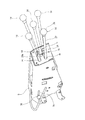
図4の変速レバー及びその周辺の斜視図であり、図5は、変速レバーの基端側の構成を示す平面図である。上述したハンドルフレーム9は、下方が開放され且つ前後方向に延びるアングル状に成形され、その開放された後端部には、方形状のレバーガイド24が嵌込み固定されている。一方、上述した変速レバー14は、突出端側である先端部にグリップ26が形成され、その他の部分であるレバー本体27が、前記レバーガイド24に穿設されたガイド孔24aに挿通されて案内される状態で、ミッションケース4側に揺動可能に支持される。
FIG. 5 is a perspective view of the shift lever of FIG. 4 and the periphery thereof, and FIG. 5 is a plan view showing a configuration of a base end side of the shift lever. The
レバー本体27におけるグリップ26の反対側の端部である基端部は、ミッションケース4内に挿通され、走行変速機構12の一又は複数(図示する例では複数)のシフト部材28を介して、該走行変速機構12の切換を行う。具体的には、前進時における高速状態(高速,前進高速段)、中速状態(中速,前進中速段)又は低速状態(低速,前進低速段)の切換と、後進状態(後進)への切換と、ニュートラル状態(ニュートラル)への切換を行う。
The base end which is the opposite end of the
ガイド孔24aはHを横に倒した形状を有し、該形状のガイド孔24aの上部における左右一方側(本例では左側)が高速位置Hになり、他方側が中速位置Mになり、下部における左右一方側(本例では左側)が後進位置Rになり、他方側が低速位置Lになり、高速位置Hと中速位置Mと後進位置Rと低速位置Lとの中間位置がニュートラル位置Nになる。
The
そして、変速レバー14におけるガイド孔24aへの挿通部分である中途部を、高速位置Hに揺動させる高速操作を行うと、走行変速機構12が高速状態に切換えられ、中速位置Mに揺動させる中速操作を行うと、走行変速機構12が中速状態に切換えられ、低速位置Lに揺動させる低速操作を行うと、走行変速機構12が低速状態に切換えられ、後進位置Rに揺動させる後進操作を行うと、走行変速機構12が後進状態に切換えられ、ニュートラル位置Nに揺動させる高速操作を行うと、走行変速機構12の動力伝動が遮断されるニュートラル状態に切換えられる。
When the intermediate portion, which is the insertion portion into the
該構造の歩行型管理機では、クラッチレバー13、変速レバー14及び作業機レバー16を適宜揺動操作し、路上走行や、圃場走行を行い、車輪7を前進走行させている最中は、耕耘ロータリを回転駆動させて、圃場の耕耘作業を行う。
In the walking type control machine of this structure, the
なお、高速側クラッチ及び低速側クラッチと、走行変速機構12と、作業機変速機構とによって、エンジン動力を、各部に伝動する伝動装置が構成される。本例では、この伝動装置の動力伝動経路の上流側に高速側クラッチ及び低速側クラッチが配置され、下流側に走行変速機構12が直列的に接続されるが、両者が伝動経路内で直列的に配置されれば、高速側クラッチ及び低速側クラッチの上流側に、走行変速機構12を配置してもよい。
The high-speed clutch and the low-speed clutch, the traveling
該構成によって、上記伝動装置は、前進時は3×2の計6段、後進時は1×2の計2段の変速を行う機能を有する。しかし、実際には、後進時に高速側クラッチからの高速動力が車輪7に伝動されると、走行速度が、速くなりすぎて走行安定性が悪くなる他、圃場での作業走行時に、走行変速機構12を高速状態に変速切換すると、耕耘作業を効率的に行うことが困難になる場合がある。このため、この歩行型管理機には、クラッチレバー13及び変速レバー14の予め定めた所定操作を、適切なタイミングで規制する規制手段が設けられている。
According to this configuration, the transmission has a function of performing a total of two stages of 3 × 2 at the time of forward movement, and a total of two stages of 1 × 2 at the reverse time. However, in practice, when high-speed power from the high-speed clutch is transmitted to the wheels 7 during reverse travel, the traveling speed becomes too fast and the traveling stability worsens. When 12 is switched to a high speed state, it may be difficult to efficiently perform the tilling work. For this reason, the walking type management machine is provided with a regulation means for regulating predetermined predetermined operations of the
次に、図3,図4,図7及び図8に基づき、規制手段の構成を詳述する。 Next, the configuration of the restricting means will be described in detail with reference to FIGS. 3, 4, 7 and 8. FIG.
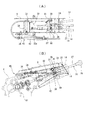
図6(A),(B)は規制手段の構成を示す平面図及び側面図であり、図7(A)は規制手段によって規制している状態を示す内側の斜視図であり、(B)は規制していない状態を示す内側の斜視図であり、図8(A),(B)は規制プレートの上面側の斜視図及び下面側の斜視図である。規制手段として、規制プレート(高速側規制部材)29と、断面視円形の規制棒31とを設けている。
6 (A) and 6 (B) are a plan view and a side view showing the structure of the restricting means, and FIG. 7 (A) is an inner perspective view showing a state of being restricted by the restricting means, (B) FIG. 8A is a perspective view of the upper surface side of the regulating plate and FIG. 8B is a perspective view of the lower surface side of the regulating plate. As a control means, a control plate (high speed side control member) 29 and a
上記規制プレート29は、チャネル状のハンドルフレーム9内の天井面側に沿って前後方向の形成され、該全長方向にスライド自在に、該ハンドルフレーム9側に支持されている。この規制プレート9の前端側には、左右方向の支持ブラケット32が固着され、後端部は下方に屈曲形成されて規制部33を構成しており、この規制部33は、後述する所定状態で、変速レバー14の高速位置Hへの揺動操作を規制するように構成されている。
The
支持ブラケット32の側端側は、ハンドルフレーム9の側部内面側に沿うように、前方に向かって屈曲形成されて支持部32aを構成しており、支持部32aには、左右方向の操作軸34が軸方向に移動可能にネジ係合されて挿通されている。この操作軸34の一端部は、ハンドルフレーム9の側部から前後方向の挿通孔9a(図4参照)を介して、外部側に突出しており、この突出した端部に、操作ノブ36が該操作軸34と一体で、軸回りに回転するように取付支持され、この操作ノブ36を、操作軸34の軸回りに回転させることにより、操作軸34及び操作ノブ36が、該操作軸34の軸方向に移動する。
The side end side of the
この挿通孔9aは、規制プレート29の前後スライド時、操作軸34のハンドルフレーム9に対する前後動を許容するように前後方向に延びる長孔状に成形されている。操作ノブ36を、ハンドルフレーム9の側面に近づく側(ロック方向)に回転させると、両者が締着固定され、これによって、規制プレート29の前後位置が固定される一方で、操作ノブ36を、ハンドルフレーム9の側面から離れる側(解除方向)に回転させると、両者の締着固定が解除され、規制プレート29を前後スライドさせることが可能になる。
The
規制プレート29を最後方位置(規制位置)にスライド移動させると、規制部33が平面視で、上記高速位置H側の臨み、変速レバー14の高速位置への揺動操作(高速操作)を規制する規制状態)に切換えられる(図7(A)参照)。一方、規制プレート29を規制位置から前方位置(非規制位置,非規制範囲)にスライド移動させると、変速レバー14の高速操作を規制しない非規制状態に切換えられる(図7(B)参照)。
When the regulating
上記規制棒31は、左右方向に延びる軸部37と、該軸部から下方に屈曲形成された規制アーム(後進側規制部材,アーム部)38とによって構成されている。軸部37は、規制プレート29の下面後寄り部分に固着された左右方向の支持筒39に軸回りに回動可能に嵌合挿入され、これによって、規制アーム38が、軸部37の軸回りに前後揺動可能に、規制プレート29側に支持される。
The restricting
なお、この規制アーム38と軸部37とは、単一の規制棒32によって一体成形されているが、これを別部材によって構成し、両者を溶接等で固定してもよい。
Although the restricting
また、軸部37における規制アーム38と反対側に端部には、連動アーム41の上端部が固着され、この連動アーム41は、軸部37の軸回りに、規制アーム38と一体で、前後揺動され、その姿勢(前後揺動位置)は、該規制アーム38と略同一になる。
Further, the upper end of the interlocking
この連動アーム41の下端部(先端部)が、連係ワイヤ42によって、上述した高速側作動アーム19と連係され、これによって、高速側クラッチとも機械的に連結される。そして、高速側クラッチが接続される上記高速状態に切換えられると、連係ワイヤ42の引き作動によって、連結アーム41が前方揺動されて作用姿勢に切換えられる一方で、高速側クラッチが切断された上記低速状態又はニュートラル状態に切換えられると、連係ワイヤ42の引き作動が解除され、これによって、連結アーム41が後方揺動されて非作用姿勢に切換えられる。
The lower end portion (tip end portion) of the interlocking
言換えると、連動アーム41及び連係ワイヤ42等は、高速側クラッチが接続された場合には規制アーム38を作用姿勢に切換えるとともに、高速側クラッチが切断された場合には、規制アーム38を非作用姿勢に切換えるように、高速側クラッチと規制アーム38とを機械的に連係させた連係機構43を構成している。
In other words, the interlocking
規制プレート29が規制位置に後方スライドされ且つ変速レバー14が中速位置又は低速位置に揺動されている状態で、規制アーム38を、非作用姿勢から作用姿勢に切換える(高速側クラッチを接続作動させる)と、該規制アーム38が、変速レバー41の後進位置Rへの揺動操作(後進操作)を規制(禁止)する状態(後進規制状態)になる。
In a state where the restricting
具体的には、後進規制状態時、変速レバー14の中途部に溶着された板状の接当片(接当部材,接当部)44と、規制アーム38との接当によって、後進操作が規制される。この接当片44は、変速レバー14の中途部から側方に突出した板状部材であり、後進規制状態では、この接当片44の変速レバー14から突出した側の端部が、後進操作を規制する後進規制部位44aになる。
Specifically, in the reverse travel restricted state, reverse operation is performed by contact between the plate-like contact piece (contact member, contact portion) 44 welded to the middle part of the
一方、規制プレート29が規制位置に後方スライドされ且つ変速レバー14が後進位置に揺動されている状態では、接当片44の後端部(高速側規制部位44b)と、規制アーム38との接当によって、該規制アーム38の非作用姿勢から作用姿勢への揺動が規制される。高速側クラッチは、連係機構43によって、規制アーム38と機械的に連係されているため、規制アーム38の作用姿勢への切換が規制されている状態では、高速側クラッチの接続作動(高速状態への切換)も規制される。
On the other hand, in a state where the restricting
また、規制プレート29が非規制位置に位置し且つ変速レバー14が中速位置又は低速位置に揺動されているとともに、規制アーム38が作用姿勢に切換えられている状態で、該規制プレート29を、規制位置に後方スライドさせると、高速操作が規制されるのに併せて、後進操作も規制される状態になる。
Further, in a state where the restricting
以上のように構成される本歩行型管理機によれば、適切なタイミングで、後進操作や、高速操作や、高速側クラッチの接続操作が規制可能なり、誤操作が効率的に防止される他、1つの操作で、後進操作の規制と、高速操作の規制とを、同時に行うことも可能であり、操作性も良好である。また、規制アーム38の断面視円形の規制棒31から構成されているため、他の部材のとの接当によって、引掛り無く、スムーズに接当及び接当解除を行うことが可能である。これに加えて、接当片44の後進規制部位44aと高速側規制部位44bとの間のコーナー部分は、規制アーム38との引掛りを低減させるように面取りされ、両者の接当はさらにスムーズになる。
According to the walking type management machine configured as described above, it is possible to regulate reverse operation, high-speed operation, and high-speed clutch connection operation at appropriate timing, and erroneous operation is efficiently prevented. It is also possible to simultaneously carry out the regulation of the reverse operation and the regulation of the high-speed operation by one operation, and the operability is also good. Further, since the restricting
また、後進状態を規制するか、或いは進状態に切換えられている場合に所定の操作を規制する各種部材(具体的には、規制部33を有する規制プレート29や、規制アーム38を有する規制棒31や、連係機構43の連動アーム41及び連係ワイヤ42や、接当片44等)を、変速レバー14側(主変速操作具側)に集中配置して、コンパクトに、ハンドルフレーム9内に収めているため、省スペース化が図られ、且つメンテナンスも容易である。
In addition, various members (specifically, the
なお、上記接当片44は、接当部として、変速レバー14の中途部に一体成形してもよく、この場合には、部品点数が減少し、さらにコスト安にすることが可能になる。
The
2 エンジン(原動機)
7 車輪(走行部)
12 走行変速機構(変速機構)
13 クラッチレバー(断続操作具)
14 変速レバー
29 規制プレート(高速側規制部材)
38 規制アーム(後進側規制部材,アーム部)
43 連係機構
44 接当片(接当部材,接当部)
2 Engine (Motor)
7 wheels (traveling part)
12 Traveling transmission mechanism (transmission mechanism)
13 Clutch lever (intermittent operation tool)
14
38 Regulating arm (Regression side regulating member, arm part)
43
Claims (1)
該伝動装置における走行部(7)への動力伝動経路の途中に配置され且つ前進時複数段及び後進時一段の変速を行う変速機構(12)と、
該伝動装置における走行部(7)への動力伝動経路の途中における変速機構(12)の伝動下流側又は上流側に配設されて高速動力を断続する高速側クラッチ及び低速動力を断続する低速側クラッチと、
前記変速機構(12)の変速操作を行う変速レバー(14)と、
前記高速側クラッチと低速側クラッチを択一的に接続させる断続操作具(13)と、
前記変速レバー(14)による上記変速機構(12)の後進への切換操作である後進操作を規制する後進側規制部材(38)とを備え、
高速側クラッチを接続させた場合には、前記後進側規制部材(38)によって、変速レバー(14)の後進操作が規制されるとともに、変速レバー(14)を後進操作させた場合には、前記後進側規制部材(38)によって、高速側クラッチの接続が規制されるように、該後進側規制部材(38)を、連係機構(43)を介して、前記高速側クラッチに機械的に連係させ、
前記後進側規制部材(38)は、高速側クラッチの断続によって揺動されるように支持された丸棒状の規制アームであり、
上記規制アーム(38)に接当する接当部(44)を、該変速レバー(14)の中途部に一体的に設け、前記高速側クラッチを接続させた場合には、規制アーム(38)と接当部(44)との接当によって、前記変速レバー(14)の後進操作が規制される一方で、前記変速レバー(14)を後進操作した場合には、規制アーム(38)と接当部(44)との接当によって、前記高速側クラッチの接続が規制される
農作業機。 A transmission that transmits power from the motor (2) to the traveling unit (7);
A transmission mechanism (12) disposed in the middle of a power transmission path to a traveling unit (7) of the transmission, and performing a plurality of speeds during forward movement and one speed change during reverse movement;
A high speed side clutch disposed on the transmission downstream side or upstream side of transmission of the transmission mechanism (12) in the middle of a power transmission path to the traveling part (7) in the transmission device for high speed clutch and low speed power With the clutch,
A shift lever (14) for shifting the transmission mechanism (12);
An on-off operation tool (13) for selectively connecting the high speed clutch and the low speed clutch;
And a reverse side regulation member (38) for regulating a reverse operation which is a switching operation of the transmission mechanism (12) to reverse by the shift lever (14).
When the high speed clutch is connected, the reverse operation of the shift lever (14) is restricted by the reverse regulating member (38) and the reverse operation of the shift lever (14) is performed. The reverse side restriction member (38) is mechanically linked to the high speed side clutch via the link mechanism (43) so that the connection of the high speed side clutch is restricted by the reverse side restriction member (38). ,
The reverse side regulation member (38) is a round bar-like regulation arm supported so as to be swung by engagement and disengagement of the high speed side clutch,
When the abutment portion (44) abutting on the regulation arm (38) is integrally provided in the middle of the speed change lever (14) and the high speed clutch is connected, the regulation arm (38) While the reverse operation of the shift lever (14) is restricted by the contact with the contact portion (44), when the shift lever (14) is operated in reverse, it contacts with the restricting arm (38). An agricultural work machine in which connection of the high-speed side clutch is regulated by contact with the part (44) .
Priority Applications (1)
| Application Number | Priority Date | Filing Date | Title |
|---|---|---|---|
| JP2015075522A JP6514006B2 (en) | 2015-04-02 | 2015-04-02 | Farm work machine |
Applications Claiming Priority (1)
| Application Number | Priority Date | Filing Date | Title |
|---|---|---|---|
| JP2015075522A JP6514006B2 (en) | 2015-04-02 | 2015-04-02 | Farm work machine |
Publications (2)
| Publication Number | Publication Date |
|---|---|
| JP2016193696A JP2016193696A (en) | 2016-11-17 |
| JP6514006B2 true JP6514006B2 (en) | 2019-05-15 |
Family
ID=57323307
Family Applications (1)
| Application Number | Title | Priority Date | Filing Date |
|---|---|---|---|
| JP2015075522A Active JP6514006B2 (en) | 2015-04-02 | 2015-04-02 | Farm work machine |
Country Status (1)
| Country | Link |
|---|---|
| JP (1) | JP6514006B2 (en) |
Family Cites Families (2)
| Publication number | Priority date | Publication date | Assignee | Title |
|---|---|---|---|---|
| JPS5739218Y2 (en) * | 1975-05-30 | 1982-08-30 | ||
| JPS54153661U (en) * | 1978-04-18 | 1979-10-25 |
-
2015
- 2015-04-02 JP JP2015075522A patent/JP6514006B2/en active Active
Also Published As
| Publication number | Publication date |
|---|---|
| JP2016193696A (en) | 2016-11-17 |
Similar Documents
| Publication | Publication Date | Title |
|---|---|---|
| JP5873751B2 (en) | Working machine | |
| JP2009220686A (en) | Walking type work machine | |
| JP7086244B2 (en) | Walking work machine | |
| JP5319609B2 (en) | Shifting operation structure of paddy field machine | |
| JP6514006B2 (en) | Farm work machine | |
| JP6467269B2 (en) | Agricultural machine | |
| JP5719533B2 (en) | Management machine | |
| JP5341822B2 (en) | Work machine transmission structure | |
| JP6533455B2 (en) | Management machine | |
| JP5722157B2 (en) | Walking type management machine | |
| JP6783427B2 (en) | Work vehicle | |
| JP2013169195A (en) | Walking type tiller | |
| JP2007030682A (en) | Walking type plant husbandry machine | |
| JP7499512B2 (en) | Walk-behind work machine | |
| JP2006224773A (en) | Walking type working machine | |
| JP5989166B2 (en) | Operating device for work equipment | |
| JP4988879B2 (en) | Working vehicle | |
| JP6444709B2 (en) | Shift restriction mechanism in walking type work machine | |
| JP5852492B2 (en) | Operating mechanism and work machine with operating mechanism | |
| JP2006224845A (en) | Shift restriction mechanism in walking type cultivator | |
| JP2011152823A (en) | Working vehicle | |
| JP5287475B2 (en) | Walking type management machine | |
| JPS6028190Y2 (en) | Operating device in reaper | |
| JP4928489B2 (en) | Walking type work machine | |
| KR102317483B1 (en) | Side clutch actuation structure for passenger type rice transplanter |
Legal Events
| Date | Code | Title | Description |
|---|---|---|---|
| A621 | Written request for application examination |
Free format text: JAPANESE INTERMEDIATE CODE: A621 Effective date: 20180228 |
|
| A977 | Report on retrieval |
Free format text: JAPANESE INTERMEDIATE CODE: A971007 Effective date: 20181214 |
|
| A131 | Notification of reasons for refusal |
Free format text: JAPANESE INTERMEDIATE CODE: A131 Effective date: 20181225 |
|
| A521 | Written amendment |
Free format text: JAPANESE INTERMEDIATE CODE: A523 Effective date: 20190219 |
|
| TRDD | Decision of grant or rejection written | ||
| A01 | Written decision to grant a patent or to grant a registration (utility model) |
Free format text: JAPANESE INTERMEDIATE CODE: A01 Effective date: 20190402 |
|
| A61 | First payment of annual fees (during grant procedure) |
Free format text: JAPANESE INTERMEDIATE CODE: A61 Effective date: 20190411 |
|
| R151 | Written notification of patent or utility model registration |
Ref document number: 6514006 Country of ref document: JP Free format text: JAPANESE INTERMEDIATE CODE: R151 |