JP6512158B2 - Vehicle cooling system - Google Patents
Vehicle cooling system Download PDFInfo
- Publication number
- JP6512158B2 JP6512158B2 JP2016081947A JP2016081947A JP6512158B2 JP 6512158 B2 JP6512158 B2 JP 6512158B2 JP 2016081947 A JP2016081947 A JP 2016081947A JP 2016081947 A JP2016081947 A JP 2016081947A JP 6512158 B2 JP6512158 B2 JP 6512158B2
- Authority
- JP
- Japan
- Prior art keywords
- radiator
- low temperature
- cooling water
- flow rate
- temperature radiator
- Prior art date
- Legal status (The legal status is an assumption and is not a legal conclusion. Google has not performed a legal analysis and makes no representation as to the accuracy of the status listed.)
- Active
Links
Images


Classifications
-
- B—PERFORMING OPERATIONS; TRANSPORTING
- B60—VEHICLES IN GENERAL
- B60K—ARRANGEMENT OR MOUNTING OF PROPULSION UNITS OR OF TRANSMISSIONS IN VEHICLES; ARRANGEMENT OR MOUNTING OF PLURAL DIVERSE PRIME-MOVERS IN VEHICLES; AUXILIARY DRIVES FOR VEHICLES; INSTRUMENTATION OR DASHBOARDS FOR VEHICLES; ARRANGEMENTS IN CONNECTION WITH COOLING, AIR INTAKE, GAS EXHAUST OR FUEL SUPPLY OF PROPULSION UNITS IN VEHICLES
- B60K11/00—Arrangement in connection with cooling of propulsion units
- B60K11/02—Arrangement in connection with cooling of propulsion units with liquid cooling
- B60K11/04—Arrangement or mounting of radiators, radiator shutters, or radiator blinds
-
- F—MECHANICAL ENGINEERING; LIGHTING; HEATING; WEAPONS; BLASTING
- F01—MACHINES OR ENGINES IN GENERAL; ENGINE PLANTS IN GENERAL; STEAM ENGINES
- F01P—COOLING OF MACHINES OR ENGINES IN GENERAL; COOLING OF INTERNAL-COMBUSTION ENGINES
- F01P3/00—Liquid cooling
- F01P3/18—Arrangements or mounting of liquid-to-air heat-exchangers
-
- F—MECHANICAL ENGINEERING; LIGHTING; HEATING; WEAPONS; BLASTING
- F01—MACHINES OR ENGINES IN GENERAL; ENGINE PLANTS IN GENERAL; STEAM ENGINES
- F01P—COOLING OF MACHINES OR ENGINES IN GENERAL; COOLING OF INTERNAL-COMBUSTION ENGINES
- F01P5/00—Pumping cooling-air or liquid coolants
- F01P5/02—Pumping cooling-air; Arrangements of cooling-air pumps, e.g. fans or blowers
- F01P5/06—Guiding or ducting air to, or from, ducted fans
-
- F—MECHANICAL ENGINEERING; LIGHTING; HEATING; WEAPONS; BLASTING
- F01—MACHINES OR ENGINES IN GENERAL; ENGINE PLANTS IN GENERAL; STEAM ENGINES
- F01P—COOLING OF MACHINES OR ENGINES IN GENERAL; COOLING OF INTERNAL-COMBUSTION ENGINES
- F01P7/00—Controlling of coolant flow
- F01P7/14—Controlling of coolant flow the coolant being liquid
- F01P7/16—Controlling of coolant flow the coolant being liquid by thermostatic control
Description
本発明は、車両の被冷却機器を冷却する冷却システムに関する。 The present invention relates to a cooling system for cooling a device to be cooled of a vehicle.
従来、特許文献1には、高水温用冷却サイクルと低水温用冷却サイクルとを備える熱エネルギー制御システムが記載されている。この従来技術では、高水温用ラジエータと低水温用ラジエータと循環ポンプと流路切替制御弁とを備えている。各々のラジエータは、第1の通路と第2の通路とを有している。 Conventionally, Patent Document 1 describes a thermal energy control system including a high water temperature cooling cycle and a low water temperature cooling cycle. In this prior art, a high water temperature radiator, a low water temperature radiator, a circulation pump, and a flow path switching control valve are provided. Each radiator has a first passage and a second passage.
低温用冷却サイクルでは、循環ポンプによって冷却水が循環され、低水温用ラジエータの第1の通路および第2の通路を流れる冷却水と冷却風によって熱交換がなされる。低温用ラジエータは、車両のエンジンルーム前方に配置されている。 In the low temperature cooling cycle, cooling water is circulated by the circulation pump, and heat exchange is performed by the cooling water and the cooling air flowing through the first passage and the second passage of the low water temperature radiator. The low temperature radiator is disposed in front of the engine room of the vehicle.
一般的な車両では、車体前部にアッパグリルとロアグリルとが設けられており、アッパグリルとロアグリルからラジエータやその他熱交換器に外気が導入され、エンジンルーム内へ流入するようになっている。アッパグリルはエンジンフードの前端近傍に配置されている。ロアグリルはアッパグリルの下方にてフロントバンパと一体に形成されている。 In a general vehicle, an upper grille and a lower grille are provided at the front of the vehicle body, and outside air is introduced from the upper grille and the lower grille to a radiator and other heat exchangers and flows into the engine room. The upper grille is disposed near the front end of the engine hood. The lower grille is integrally formed with the front bumper below the upper grille.
近年、一部の車両においては、燃費の向上を目的として、アッパグリルまたはロアグリルに外気のシャット機構が設けられている。そして、特に高速走行時、シャット機構を閉状態としてエンジンルーム内への空気の流入を制限することにより、その空力性能(例えば「Cd値」等)を向上させることができるので車両の走行抵抗を低減させ、燃費を向上させることができる。 In recent years, in some vehicles, an upper grille or a lower grille is provided with an outdoor air shut mechanism for the purpose of improving fuel consumption. And, especially when traveling at high speed, by closing the shut mechanism and restricting the inflow of air into the engine room, it is possible to improve its aerodynamic performance (for example, "Cd value" etc.), and therefore the running resistance of the vehicle It is possible to reduce the fuel consumption.
上記特許文献1の従来技術を、ロアグリルにシャッタ機構が設けられた車両に適用した場合、低温用ラジエータの第1の通路がアッパグリルに対向し、低温用ラジエータの第2の通路がロアグリルに対向することとなる。そのため、シャット機構を閉状態にすると低温用ラジエータの第2の通路には外気がほとんど流れなくなる。 When the prior art of Patent Document 1 is applied to a vehicle in which the lower grille is provided with the shutter mechanism, the first passage of the low temperature radiator faces the upper grille, and the second passage of the low temperature radiator faces the lower grille. It will be. Therefore, when the shut mechanism is closed, outside air hardly flows in the second passage of the low temperature radiator.
しかるに、上記特許文献1の従来技術では、低温用ラジエータの第1の通路および第2の通路の両方に常に冷却水が流れるので、シャッタ機構を閉状態にすると第2の通路には外気がほとんど流れないにもかかわらず冷却水(換言すれば熱媒体)が流れるという無駄が発生してしまう。 However, in the prior art of Patent Document 1, since the cooling water always flows in both the first passage and the second passage of the low temperature radiator, when the shutter mechanism is closed, most of the open air is in the second passage. Although it does not flow, the waste that a cooling water (in other words, a heat carrier) flows will occur.
本発明は上記点に鑑みて、ラジエータに熱媒体を効率的に流すことを目的とする。 An object of the present invention is to efficiently flow a heat medium to a radiator in view of the above-mentioned point.
上記目的を達成するため、請求項1に記載の車両用冷却システムでは、
熱媒体によって冷却される被冷却機器(32、33、34)と、
車両の開口部(21、22)から導入された外気と熱媒体とを熱交換させる第1ラジエータ(11)および第2ラジエータ(12)と、
開口部の開口面積を調整する開口面積調整部(23)と、
第1ラジエータを流れる熱媒体と第2ラジエータを流れる熱媒体との流量割合を調整する流量割合調整部(35)と、
開口面積調整部の作動状態に応じて流量割合調整部の作動を制御する制御部(60)とを備え、
制御部は、車両の走行速度が所定速度を上回ると、第1ラジエータおよび第2ラジエータのうち一方のラジエータへの外気の導入が抑制されるように開口面積調整部を制御するとともに一方のラジエータを流れる熱媒体の流量が減少するように流量割合調整部を制御する。
In order to achieve the above object, in a vehicle cooling system according to claim 1,
Cooled equipment (32, 33, 34) cooled by the heat medium;
A first radiator (11) and a second radiator (12) for exchanging heat between the heat transfer medium and the outside air introduced from the opening (21, 22) of the vehicle;
An opening area adjustment unit (23) for adjusting the opening area of the opening;
A flow rate ratio adjusting unit (35) for adjusting a flow rate ratio between the heat medium flowing through the first radiator and the heat medium flowing through the second radiator;
A control unit (60) for controlling the operation of the flow rate adjustment unit in accordance with the operation state of the opening area adjustment unit ;
The control unit controls the opening area adjustment unit such that the introduction of the outside air to one of the first and second radiators is suppressed when the traveling speed of the vehicle exceeds the predetermined speed, and the one radiator is The flow rate adjustment unit is controlled so that the flow rate of the flowing heat medium decreases.
これによると、第1ラジエータ(11)および第2ラジエータ(12)への外気の導入状態に応じて、第1ラジエータ(11)および第2ラジエータ(12)に対する熱媒体の流量割合を変化させることができる。そのため、第1ラジエータ(11)および第2ラジエータ(12)に熱媒体を効率的に流すことができる。 According to this, the flow rate ratio of the heat medium to the first radiator (11) and the second radiator (12) is changed according to the introduction state of the outside air to the first radiator (11) and the second radiator (12) Can. Therefore, the heat medium can be efficiently flowed through the first radiator (11) and the second radiator (12).
また、外気の導入が抑制されているラジエータに冷却水が無駄に流れることを抑制できる。
上記目的を達成するため、請求項3に記載の車両用冷却システムでは、
熱媒体によって冷却される被冷却機器(32、33、34)と、
車両の開口部(21、22)から導入された外気と熱媒体とを熱交換させる第1ラジエータ(11)および第2ラジエータ(12)と、
開口部の開口面積を調整する開口面積調整部(23)と、
第1ラジエータを流れる熱媒体と第2ラジエータを流れる熱媒体との流量割合を調整する流量割合調整部(35)と、
開口面積調整部の作動状態に応じて流量割合調整部の作動を制御する制御部(60)とを備え、
制御部は、第1ラジエータおよび第2ラジエータのうち一方のラジエータへの外気の導入が抑制されるように開口面積調整部が作動している場合、一方のラジエータを流れる熱媒体の流量が減少するように流量割合調整部の作動を制御し、
制御部は、車両の走行速度が所定速度を上回ると一方のラジエータへの外気の導入が抑制されるように開口面積調整部の作動を制御し、
第1ラジエータおよび第2ラジエータの熱交換量の特性を比較すると、流入する外気の速度が所定速度を上回っている場合、一方のラジエータの熱交換量よりも他方のラジエータの熱交換量の方が多くなるように、第1ラジエータおよび第2ラジエータが形成されている。
これにより、請求項1に記載の車両用冷却システムと同様の作用効果を奏することができる。
Moreover, it can suppress that a cooling water flows uselessly to the radiator by which introduction | transduction of external air is suppressed.
In order to achieve the above object, in the vehicle cooling system according to claim 3,
Cooled equipment (32, 33, 34) cooled by the heat medium;
A first radiator (11) and a second radiator (12) for exchanging heat between the heat transfer medium and the outside air introduced from the opening (21, 22) of the vehicle;
An opening area adjustment unit (23) for adjusting the opening area of the opening;
A flow rate ratio adjusting unit (35) for adjusting a flow rate ratio between the heat medium flowing through the first radiator and the heat medium flowing through the second radiator;
A control unit (60) for controlling the operation of the flow rate adjustment unit in accordance with the operation state of the opening area adjustment unit;
The control unit decreases the flow rate of the heat medium flowing through one of the radiators when the opening area adjustment unit is operated so as to suppress the introduction of the outside air to one of the first and second radiators. To control the operation of the flow rate adjustment unit,
The control unit controls the operation of the opening area adjustment unit such that the introduction of outside air to one of the radiators is suppressed when the traveling speed of the vehicle exceeds a predetermined speed,
Comparing the characteristics of the heat exchange amount of the first radiator and the second radiator, when the speed of the outside air flowing in exceeds the predetermined speed, the heat exchange amount of the other radiator is more than the heat exchange amount of one radiator The first and second radiators are formed to increase the number.
Thereby, the same operation and effect as the vehicle cooling system according to claim 1 can be obtained.
なお、この欄および特許請求の範囲で記載した各手段の括弧内の符号は、後述する実施形態に記載の具体的手段との対応関係を示すものである。 In addition, the code | symbol in the parenthesis of each means described by this column and the claim shows correspondence with the specific means as described in embodiment mentioned later.
以下、車両用冷却システムの一実施形態を図に基づいて説明する。図1の上下前後の矢印は、車両用冷却システムが搭載される車両における上下前後の各方向を示している。 Hereinafter, an embodiment of a cooling system for a vehicle will be described based on the drawings. Arrows in the upper, lower, front, and back directions in FIG. 1 indicate the respective directions in the upper, lower, front, and back directions in the vehicle on which the vehicle cooling system is mounted.
図1に示すように、第1低温ラジエータ11、第2低温ラジエータ12、エンジン冷却用ラジエータ13および送風機14は、車両のエンジンルーム15の前部に配置されている。
As shown in FIG. 1, the first
第1低温ラジエータ11、第2低温ラジエータ12、エンジン冷却用ラジエータ13および送風機14は一体の組立構造体を構成している。すなわち、第1低温ラジエータ11、第2低温ラジエータ12およびエンジン冷却用ラジエータ13および送風機14はクーリングモジュールを構成している。
The first
第1低温ラジエータ11、第2低温ラジエータ12およびエンジン冷却用ラジエータ13は、共通のフロントエンドパネル16内に組み込まれている。フロントエンドパネル16は、第1低温ラジエータ11、第2低温ラジエータおよびエンジン冷却用ラジエータ13の周囲を支持するとともに第1低温ラジエータ11、第2低温ラジエータ12およびエンジン冷却用ラジエータ13を通過する空気流をガイドする部材である。
The first
第1低温ラジエータ11および第2低温ラジエータ12は、図2に示す低温冷却水回路30の冷却水と車室外の空気(以下、外気と言う。)とを熱交換させる熱交換器である。エンジン冷却用ラジエータ13は、図2に示すエンジン冷却水回路40の冷却水と外気とを熱交換させる熱交換器である。
The first low-
エンジン冷却用ラジエータ13は、第1低温ラジエータ11および第2低温ラジエータ12の外気流れ下流側に配置されている。すなわち、エンジン冷却用ラジエータ13は、第1低温ラジエータ11および第2低温ラジエータ12の車両後方側に配置されている。
The
低温冷却水回路30およびエンジン冷却水回路40は、冷却水が循環する冷却水循環回路である。低温冷却水回路30およびエンジン冷却水回路40は、互いに独立した冷却水回路である。
The low temperature
冷却水は、熱媒体としての流体である。例えば、冷却水は、エチレングリコール系の不凍液(いわゆるLLC)である。 Cooling water is a fluid as a heat carrier. For example, the cooling water is ethylene glycol antifreeze (so-called LLC).
送風機14は、第1低温ラジエータ11、第2低温ラジエータおよびエンジン冷却用ラジエータ13に向けて空気を送風する送風部である。送風機14は、軸流ファンを電動モータにて駆動する電動送風機である。
The
エンジンルーム15の前端部には、バンパーリーンフォース17およびバンパーカバー18が配置されている。バンパーリーンフォース17は、車両の前端部にて車両幅方向に延びて車両前面側からの衝突力を吸収する梁状の部材である。バンパーカバー18は、バンパーリーンフォース17の前面側に配置されている。バンパーカバー18は、バンパーリーンフォース17の前面側を覆う樹脂製の部品である。
A
エンジンルーム15の上面開口部はエンジンフード19によって閉塞されている。エンジンルーム15の下方側にはアンダーカバー20が配置されている。
The top opening of the
バンパーリーンフォース17の上方側には上方側開口部21が設けられている。バンパーリーンフォース17の下方側には下方側開口部22が設けられている。上方側開口部21および下方側開口部22は、エンジンルーム15内の第1低温ラジエータ11、第2低温ラジエータおよびエンジン冷却用ラジエータ13に外気を導入する外気導入口である。
An
第1低温ラジエータ11は、エンジンルーム15内において、上方側開口部21と対向する位置に配置されている。第2低温ラジエータ12は、エンジンルーム15内において、下方側開口部22と対向する位置に配置されている。
The first low-
下方側開口部22にはシャッタ機構23が配置されている。シャッタ機構23は、下方側開口部22を開閉することによって、下方側開口部22から導入される空気の風量を調整する導入風量調整部である。
A
シャッタ機構23は、下方側開口部22の開口面積を調整する開口面積調整部である。換言すれば、シャッタ機構23は、上方側開口部21および下方側開口部22のうち第2低温ラジエータ12と対向する部位の開口面積を調整する。
The
シャッタ機構23は、複数枚の板ドアを有している。シャッタ機構23は、図2に示す電動アクチュエータ24によって駆動されて回転変位する。電動アクチュエータ24が複数枚の板ドアを連動して回転変位させることによって下方側開口部22が開閉される。
The
図1は、シャッタ機構23が下方側開口部22を閉じた状態を示している。図3は、シャッタ機構23が下方側開口部22を開いた状態を示している。
FIG. 1 shows a state in which the
シャッタ機構23は高速走行時(例えば80km/h以上で走行しているとき)に下方側開口部22を閉じる。これにより、高速走行時の空力性能(例えば「Cd値」等)を向上させる。シャッタ機構23が下方側開口部22を閉じた場合、下方側開口部22から外気が導入されないので、第2低温ラジエータ12に外気がほとんど流れない。
The
シャッタ機構23は、高速走行時および低外気温時以外は下方側開口部22を開く。シャッタ機構23が下方側開口部22を開いた場合、下方側開口部22から外気が導入されるので、第2低温ラジエータ12に外気が流れる。
The
図1の例では、アンダーカバー20の近傍にバンパーリーンフォース25が配置されている。
In the example of FIG. 1, the
図2に示すように、第1低温ラジエータ11および第2低温ラジエータ12は、低温冷却水回路30の冷却水流れにおいて互いに並列に配置されている。第1低温ラジエータ11は、低温冷却水回路30の第1ラジエータである。第2低温ラジエータ12は、低温冷却水回路30の第2ラジエータである。
As shown in FIG. 2, the first
低温冷却水回路30には、低温冷却水ポンプ31、ターボチャージャ32、インタークーラ33、冷媒放熱器34、第1切替弁35および第2切替弁36が配置されている。
In the low temperature cooling
低温冷却水ポンプ31は、低温冷却水回路30の冷却水を吸入して吐出する電動ポンプである。ターボチャージャ32、インタークーラ33および冷媒放熱器34は、低温冷却水回路30の冷却水によって冷却される被冷却機器である。
The low temperature cooling
ターボチャージャ32は、エンジン41の吸気を過給する過給機である。インタークーラ33は、ターボチャージャ32で圧縮されて高温になった過給吸気と冷却水とを熱交換して過給吸気を冷却する吸気冷却器である。
The
ターボチャージャ32およびインタークーラ33は、低温冷却水回路30の冷却水流れにおいて互いに並列に配置されている。さらに、ターボチャージャ32およびインタークーラ33は、低温冷却水回路30の冷却水流れにおいて冷媒放熱器34と並列に配置されている。
The
冷媒放熱器34は、冷凍サイクル50の高温高圧冷媒と低温冷却水回路30の冷却水とを熱交換して冷媒を冷却する熱交換器である。冷凍サイクル50は、圧縮機51、冷媒放熱器34、膨張弁52および蒸発器53を有している。
The
圧縮機51は、冷凍サイクル50の低圧冷媒を吸入して圧縮し、高圧冷媒を吐出する。冷媒放熱器34は、圧縮機51が吐出した高圧冷媒と低温冷却水回路30の冷却水とを熱交換して高圧冷媒を冷却する。膨張弁52は、冷媒放熱器34で冷却された高圧冷媒を減圧膨張させる減圧部である。蒸発器53は、膨張弁52で減圧された低圧冷媒と、車室内へ送風される空気とを熱交換させて車室内へ送風される空気を冷却する空調用熱交換器である。
The
第1切替弁35は、第1低温ラジエータ11を流れる冷却水と第2低温ラジエータ12を流れる冷却水との流量割合を調整する流量割合調整部である。第1切替弁35は、第1低温ラジエータ11側の冷却水流路と第2低温ラジエータ12側の冷却水流路との分岐部に配置されている。第1切替弁35は、第2低温ラジエータ12側の冷却水流路を開閉する電磁弁である。
The
第1切替弁35が第2低温ラジエータ12側の冷却水流路を開けると、第1低温ラジエータ11および第2低温ラジエータ12の両方に冷却水が流れる。第1切替弁35が第2低温ラジエータ12側の冷却水流路を閉じると、第1低温ラジエータ11に冷却水が流れ、第2低温ラジエータ12に冷却水が流れなくなる。
When the
第2切替弁36は、ターボチャージャ32およびインタークーラ33を流れる冷却水と冷媒放熱器34を流れる冷却水との流量割合を調整する流量割合調整部である。
The
第2切替弁36は、ターボチャージャ32およびインタークーラ33側の冷却水流路と冷媒放熱器34側の冷却水流路との分岐部に配置されている。第2切替弁36は、ターボチャージャ32およびインタークーラ33側の冷却水流路を開閉する電磁弁である。
The
第2切替弁36がターボチャージャ32およびインタークーラ33側の冷却水流路を開けると、ターボチャージャ32、インタークーラ33および冷媒放熱器34に冷却水が流れる。第2切替弁36がターボチャージャ32およびインタークーラ33側の冷却水流路を閉じると、冷媒放熱器34に冷却水が流れ、ターボチャージャ32およびインタークーラ33に冷却水が流れなくなる。
When the
エンジン冷却水回路40には、エンジン41およびエンジン冷却水ポンプ42が配置されている。エンジン冷却水ポンプ42は、エンジン冷却水回路40の冷却水を吸入して吐出するポンプである。エンジン冷却水ポンプ42は、エンジン41の駆動力をベルトを介して動力伝達することによって駆動されるベルト駆動式ポンプである。エンジン冷却水ポンプ42は電動ポンプであってもよい。
In the
シャッタ機構23を駆動する電動アクチュエータ24、低温冷却水ポンプ31、第1切替弁35、第2切替弁36および送風機14の作動は、制御装置60から出力される制御信号によって制御される。
The operations of the
制御装置60は、CPU、ROMおよびRAM等を含む周知のマイクロコンピュータとその周辺回路から構成され、ROM内に記憶された制御プログラムに基づいて各種演算、処理を行い、出力側に接続された各種機器の作動を制御する。
The
制御装置60は、車両用冷却システムを構成する各種制御機器の作動を制御する制御部である。制御装置60は、乗員が車両のイグニッションスイッチを投入した際に、図示しないバッテリから電力が供給されて起動する。
The
制御装置60の出力側には、シャッタ機構23を駆動する電動アクチュエータ24、低温冷却水ポンプ31、第1切替弁35、第2切替弁36およびエンジン冷却水ポンプ42が接続されている。
At the output side of the
制御装置60の入力側には、車速センサ61、外気温センサ62、吸気温度センサ63、冷媒圧力センサ64等のセンサ群が接続されている。
A sensor group such as a vehicle speed sensor 61, an outside air temperature sensor 62, an intake
車速センサ61は、車両の走行速度を検出する走行速度検出部である。外気温センサ62は、車室外温度(すなわち、外気温)Tamを検出する外気温度検出部である。吸気センサ63は、インタークーラ33に流入する吸気の温度を検出する吸気温度検出部である。吸気センサ63は、インタークーラ33に流入する吸気の圧力を検出する吸気圧力検出部であってもよい。
The vehicle speed sensor 61 is a traveling speed detection unit that detects the traveling speed of the vehicle. The outside air temperature sensor 62 is an outside air temperature detection unit that detects the temperature outside the vehicle compartment (that is, the outside air temperature) Tam. The
冷媒圧力センサ64は、図示しない冷凍サイクルの圧力を検出する冷媒圧力検出部である。例えば、冷媒圧力センサ64は、冷凍サイクル50の圧縮機51から吐出されて冷媒放熱器34に流入する冷媒の圧力を検出する。
The
図4に示すように、第1低温ラジエータ11および第2低温ラジエータ12は、互いに分離している。第1低温ラジエータ11および第2低温ラジエータ12は、正面面積が互いに同じになっている。
As shown in FIG. 4, the first
図5の変形例に示すように、第1低温ラジエータ11および第2低温ラジエータ12は、互いに一体化されていてもよい。
As shown in the modification of FIG. 5, the first
図6の変形例に示すように、第1低温ラジエータ11および第2低温ラジエータ12は、正面面積が互いに異なっていてもよい。図6の例では、第1低温ラジエータ11の正面面積が第2低温ラジエータ12の正面面積よりも大きくなっているが、第2低温ラジエータ12の正面面積が第1低温ラジエータ11の正面面積よりも大きくなっていてもよい。
As shown in the modification of FIG. 6, the first
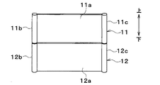
第1低温ラジエータ11および第2低温ラジエータ12はそれぞれ、コア部11a、12aとタンク11b、11c、12b、12cとを有している。コア部11a、12aは、冷却水と空気とを熱交換する熱交換部である。コア部11a、12aは、略矩形状に形成されている。コア部11a、12aは、多数本のチューブとフィンとを有している。
The first low-
チューブは、冷却水が流れる配管である。チューブは、多数本、互いに並行に配置されている。フィンは、チューブの扁平面に接合されている。フィンは、伝熱面積を増大させて冷媒と空気との熱交換を促進する熱交換促進部材である。例えば、フィンは、波状に成形されたコルゲートフィンである。 The tube is a pipe through which cooling water flows. A large number of tubes are arranged parallel to one another. The fins are joined to the flat surface of the tube. The fins are heat exchange promoting members that increase the heat transfer area to promote heat exchange between the refrigerant and the air. For example, the fins are corrugated fins shaped in a wave shape.
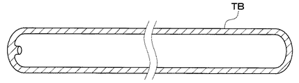
図7に示すように、チューブTBは、扁平状に形成された扁平チューブである。チューブは、扁平面が空気の流れ方向に沿うように配置されている。 As shown in FIG. 7, the tube TB is a flat tube formed in a flat shape. The tubes are arranged such that the flat surface is in the air flow direction.
タンク11b、11c、12b、12cは、チューブTBの両端部に接合されている。タンク11b、11c、12b、12cは、多数本のチューブTBに対して、冷却水の分配および集合を行う。
The
図7の例では、チューブTBはフラットチューブである。図8の変形例に示すように、チューブは、インナーフィンIFを有するインナーフィンチューブであってもよい。図9の変形例に示すように、チューブは、ディンプルDPが形成されたディンプルチューブであってもよい。 In the example of FIG. 7, the tube TB is a flat tube. As shown in the modification of FIG. 8, the tube may be an inner fin tube having an inner fin IF. As shown in the modification of FIG. 9, the tube may be a dimpled tube in which dimples DP are formed.
図10に示すように、第1低温ラジエータ11および第2低温ラジエータ12のコア部11a、12aでは、冷却水が一方のタンク11b、11c、12b、12c側から他方のタンク11b、11c、12b、12c側に向かって一方向に流れる。
As shown in FIG. 10, in the
図11の変形例に示すように、第1低温ラジエータ11および第2低温ラジエータ12のコア部11a、12aでは、冷却水が一方のタンク11b、11c、12b、12c側から他方のタンク側に向かって流れ、他方のタンク11b、11c、12b、12cでUターンして一方のタンク11b、11c、12b、12c側に向かって流れてもよい。
As shown in the modification of FIG. 11, in the
図12の変形例に示すように、第1低温ラジエータ11のコア部11a、12aでは冷却水がUターンして流れ、第2低温ラジエータ12のコア部11a、12aでは冷却水が一方向に流れてもよい。
As shown in the modification of FIG. 12, the cooling water U-turns and flows in the
第1低温ラジエータ11および第2低温ラジエータ12の性能特性は互いに異なっている。具体的には、流入する外気の風速が高風速域である場合、第1低温ラジエータ11の熱交換量が第2低温ラジエータ12の熱交換量よりも多くなるように第1低温ラジエータ11および第2低温ラジエータ12が形成されている。
The performance characteristics of the first
高風速域とは、シャッタ機構23が下方側開口部22を閉じる高速走行時(例えば80km/h以上で走行しているとき)に第1低温ラジエータ11に流入する外気の風速域(例えば約80km/h以上)のことである。
The high wind speed range is the wind speed range (for example, about 80 km) of the outside air flowing into the first
また、流入する外気の風速が低速域である場合、第2低温ラジエータ12の熱交換量が第1低温ラジエータ11の熱交換量よりも多くなるように第1低温ラジエータ11および第2低温ラジエータ12が形成されている。
In addition, when the wind speed of the inflowing external air is in the low speed region, the first
具体的には、第1低温ラジエータ11では冷却に対する空気側の寄与度が第2低温ラジエータ12と比較して大きく、第2低温ラジエータ12では冷却に対する冷却水側の寄与度が第1低温ラジエータ11と比較して大きくなるように第1低温ラジエータ11および第2低温ラジエータ12が形成されている。
Specifically, in the first low-
例えば、第1低温ラジエータ11のフィンルーバの枚数を第2低温ラジエータ12のフィンルーバの枚数よりも多くすることによって、第1低温ラジエータ11の冷却に対する空気側の寄与度を第2低温ラジエータ12と比較して大きくできる。
For example, by making the number of fin louvers of the first
例えば、第1低温ラジエータ11のフィンピッチを第2低温ラジエータ12のフィンピッチよりも小さくすることによって、第1低温ラジエータ11の冷却に対する空気側の寄与度を第2低温ラジエータ12と比較して大きくできる。
For example, by making the fin pitch of the first
例えば、第1低温ラジエータ11のチューブにインナーフィンやディンプルを設けず、第2低温ラジエータ12のチューブにインナーフィンやディンプルを設けることによって、第2低温ラジエータ12の冷却に対する冷却水側の寄与度を第1低温ラジエータ11と比較して大きくできる。
For example, by providing the inner fins and dimples in the tube of the second
例えば、第1低温ラジエータ11のチューブの外気流れ方向幅寸法を第2低温ラジエータ12のチューブの外気流れ方向幅寸法よりも大きくすることによって、第2低温ラジエータ12の冷却に対する冷却水側の寄与度を第1低温ラジエータ11と比較して大きくできる。
For example, by making the outside air flow direction width dimension of the tube of the first
次に、上記構成における作動を説明する。制御装置60は、走行シーンに応じてシャッタ駆動用電動アクチュエータ24、第1切替弁35および第2切替弁36の作動を制御する。
Next, the operation in the above configuration will be described. The
例えば、制御装置60は、エンジン41がアイドル状態である場合や市街地走行時である場合、シャッタ機構23が下方側開口部22を開き、第1切替弁35が第2低温ラジエータ12側の冷却水流路を開き、第2切替弁36がターボチャージャ32およびインタークーラ33側の冷却水流路を閉じる。
For example, when the
このとき、送風機14を作動させて外気を送風する。エンジン41がアイドル状態である場合は走行風が得られず、市街地走行時は得られる走行風が少ないからである。
At this time, the
これにより、上方側開口部21および下方側開口部22の両方から外気が導入され、第1低温ラジエータ11、第2低温ラジエータ12および冷媒放熱器34に低温冷却水回路30の冷却水が流れ、ターボチャージャ32およびインタークーラ33に低温冷却水回路30の冷却水が流れない、またはターボチャージャ32およびインタークーラ33に低温冷却水回路30の冷却水が流れても必要最小限の流量となる。
Thereby, the outside air is introduced from both the
すなわち、低温冷却水回路30では、冷媒放熱器34で冷凍サイクルの高温冷媒から冷却水に放熱され、第1低温ラジエータ11および第2低温ラジエータ12で冷却水から外気に放熱される。そのため、冷凍サイクルの蒸発器53における空気の冷却性能を確保できる。換言すれば、空調性能を確保できる。
That is, in the low temperature cooling
エンジン41がアイドル状態である場合や市街地走行時である場合にはターボチャージャ32で吸気の過給がほとんど行われないので、ターボチャージャ32およびインタークーラ33に冷却水が流れなくても支障はない。
When the
例えば、制御装置60は、低速登坂時や牽引時のような高負荷なエンジン動作状態である場合、シャッタ機構23が下方側開口部22を開き、第1切替弁35が第2低温ラジエータ12側の冷却水流路を開き、第2切替弁36がターボチャージャ32およびインタークーラ33側の冷却水流路を開く。
For example, when the
これにより、上方側開口部21および下方側開口部22の両方から外気が導入され、第1低温ラジエータ11、第2低温ラジエータ12、冷媒放熱器34、ターボチャージャ32およびインタークーラ33に低温冷却水回路30の冷却水が流れる。
Thus, the outside air is introduced from both the
すなわち、低温冷却水回路30では、冷媒放熱器34で冷凍サイクルの高温冷媒から冷却水に放熱され、ターボチャージャ32から冷却水に放熱され、インタークーラ33で過給吸気から冷却水に放熱され、第1低温ラジエータ11および第2低温ラジエータ12で冷却水から外気に放熱される。
That is, in the low temperature cooling
したがって、ターボチャージャ32で吸気の過給が行われる低速登坂時や牽引時に、ターボチャージャ32や過給吸気を確実に冷却できる。また、冷凍サイクルの蒸発器53における空気の冷却性能を確保できる。換言すれば、空調性能を確保できる。
Therefore, the
また、上方側開口部21および下方側開口部22の両方から導入された外気がエンジン冷却用ラジエータ13を流れるので、エンジン負荷が高くなる低速登坂時や牽引時であっても、エンジン41を十分に冷却できる。
In addition, since the outside air introduced from both the
例えば、制御装置60は、高速走行中である場合、シャッタ機構23が下方側開口部22を閉じ、第1切替弁35が第2低温ラジエータ12側の冷却水流路を閉じ、第2切替弁36がターボチャージャ32およびインタークーラ33側の冷却水流路を開く。
For example, when the
これにより、下方側開口部22から外気が導入されず、第1低温ラジエータ11、冷媒放熱器34、ターボチャージャ32およびインタークーラ33に低温冷却水回路30の冷却水が流れ、第2低温ラジエータ12に低温冷却水回路30の冷却水が流れない。
As a result, the outside air is not introduced from the
すなわち、下方側開口部22からエンジンルーム15に外気が流入しなくなるので、車両の空気抵抗係数が低減し、ひいては燃費が向上する。
That is, since the outside air does not flow from the
下方側開口部22から外気が導入されないので、第2低温ラジエータ12に外気がほとんど流れなくなる。そこで、第2低温ラジエータ12に冷却水が流れないようにするので、第2低温ラジエータ12に無駄に冷却水が流れることを回避できる。
Since the outside air is not introduced from the
このとき、第1低温ラジエータ11を流れる冷却水の流量が過剰にならないように低温冷却水ポンプ31の回転数が低く制御される。これにより、低温冷却水ポンプ31の消費電力を低減できる。
At this time, the rotational speed of the low
また、低温冷却水回路30では、冷媒放熱器34で冷凍サイクルの高温冷媒から冷却水に放熱され、ターボチャージャ32から冷却水に放熱され、インタークーラ33で過給吸気から冷却水に放熱され、第1低温ラジエータ11で冷却水から外気に放熱される。
Further, in the low temperature cooling
高速走行時であるので、第1低温ラジエータ11に流入する外気の風速は高速域になる。上述のように、流入する外気の風速が高風速域である場合、第1低温ラジエータ11の熱交換量が多くなるように第1低温ラジエータ11が形成されている。
Since the vehicle is traveling at high speed, the wind speed of the outside air flowing into the first
したがって、ターボチャージャ32で吸気の過給が行われる高速走行時に、ターボチャージャ32や過給吸気を確実に冷却できる。また、冷凍サイクルの蒸発器53における空気の冷却性能を確保できる。換言すれば、空調性能を確保できる。
Therefore, the
また、エンジン冷却水回路40では、エンジン41から冷却水に放熱され、エンジン冷却用ラジエータ13で冷却水から外気に放熱されるので、エンジン41を冷却できる。
Further, in the engine
例えば、制御装置60は、エンジン41をアイドルアップして暖機する冷間時である場合、高速走行中である場合と同様にシャッタ機構23、第1切替弁35および第2切替弁36の作動を制御する。
For example, when it is a cold time when the
これにより、下方側開口部22から外気が導入されないので、エンジン冷却用ラジエータ13を流れる外気の風量が少なくなる。そのため、エンジン冷却用ラジエータ13にて冷却水から外気に放熱される放熱量が少なくなるので、エンジン冷却水回路40の冷却水温度を早期に上昇させてエンジン41を早期に暖機させることができる。
As a result, the outside air is not introduced from the
下方側開口部22から外気が導入されないので、第2低温ラジエータ12に外気がほとんど流れなくなる。そこで、第2低温ラジエータ12に冷却水が流れないようにするので、第2低温ラジエータ12に無駄に冷却水が流れることを回避できる。
Since the outside air is not introduced from the
このとき、第1低温ラジエータ11を流れる冷却水の流量が過剰にならないように低温冷却水ポンプ31の回転数が低く制御される。これにより、低温冷却水ポンプ31の消費電力を低減できる。
At this time, the rotational speed of the low
このように、走行シーンに応じて第1低温ラジエータ11および第2低温ラジエータ12に対する冷却水の流れを切り替えることによって、被冷却機器32、33、34を必要に応じて適切に冷却することができる。
Thus, by switching the flow of the cooling water to the first low-
換言すれば、第1低温ラジエータ11および第2低温ラジエータ12の熱交換能力を適切に調整して、被冷却機器32、33、34を効率的に冷却できる。
In other words, the heat exchange capabilities of the first low-
また、被冷却機器32、33、34を効率的に冷却できるので、車両の開口部21、22のデザインの自由度を向上させることができる。
In addition, since the devices to be cooled 32, 33, 34 can be cooled efficiently, the degree of freedom in design of the
本実施形態では、制御装置60は、シャッタ機構23の作動状態に応じて第1切替弁35の作動を制御する。
In the present embodiment, the
これによると、第1低温ラジエータ11および第2低温ラジエータ12への外気の導入状態に応じて、第1低温ラジエータ11および第2低温ラジエータ12に対する冷却水の流量割合を変化させることができる。そのため、第1低温ラジエータ11および第2低温ラジエータ12に冷却水を効率的に流すことができる。
According to this, it is possible to change the flow rate ratio of the cooling water with respect to the first
具体的には、制御装置60は、第2低温ラジエータ12への外気の導入が抑制されるようにシャッタ機構23が作動している場合、第2低温ラジエータ12を流れる冷却水の流量が減少するように第1切替弁35の作動を制御する。
Specifically, the
これによると、外気の導入が抑制されている第2低温ラジエータ12に冷却水が無駄に流れることを抑制できる。
According to this, it is possible to suppress the wasteful flow of the cooling water to the second
制御装置60は、車両の走行速度が所定速度を上回ると第2低温ラジエータ12への外気の導入が抑制されるようにシャッタ機構23の作動を制御する。そして、第1低温ラジエータ11および第2低温ラジエータ12の熱交換量の特性を比較すると、流入する外気の速度が所定速度を上回っている場合、第2低温ラジエータ12の熱交換量よりも第1低温ラジエータ11の熱交換量の方が多くなるように、第1低温ラジエータ11および第2低温ラジエータ12が形成されている。
The
これによると、シャッタ機構23が第2低温ラジエータ12への外気の導入を抑制している場合、第1低温ラジエータ11の熱交換量を多くすることができる。そのため、第2低温ラジエータ12への外気の導入を抑制している場合であっても、低温冷却水回路30の冷却水と外気との熱交換量が不足することを抑制できる。
According to this, when the
具体的には、制御装置60は、下方側開口部22が閉塞されるようにシャッタ機構23が作動している場合、第2低温ラジエータ12に対して冷却水の流れが遮断されるように第1切替弁35の作動を制御する。
Specifically, when the
これによると、下方側開口部22が閉塞されて第2低温ラジエータ12に外気がほとんど導入されない場合に第2低温ラジエータ12に冷却水が無駄に流れることを抑制できる。
According to this, when the lower
本実施形態では、第1低温ラジエータ11および第2低温ラジエータ12は、冷却水の流れにおいて互いに並列に配置されている。そして、第1切替弁35は、冷却水の流れを第1低温ラジエータ11側と第2低温ラジエータ12側とに分岐する分岐部に配置されたバルブである。
In the present embodiment, the first
これによると、簡素な構成にて、第1低温ラジエータ11および第2低温ラジエータ12に対する冷却水の流量割合を変化させることができる。
According to this, the flow rate ratio of the cooling water to the first
(他の実施形態)
上記実施形態を例えば以下のように種々変形可能である。
(Other embodiments)
The above embodiment can be variously modified as follows, for example.
(1)上記実施形態では、シャッタ機構23は下方側開口部22を開閉するようになっているが、シャッタ機構23は下方側開口部22の開度を任意に調整するようになっていてもよい。
(1) In the above embodiment, the
(2)上記実施形態では、シャッタ機構23が下方側開口部22に配置されているが、シャッタ機構23が上方側開口部21に配置されていてもよい。この場合、制御装置60は、シャッタ機構23が閉じられると第1低温ラジエータ11側の冷却水流路を閉じて第1低温ラジエータ11に冷却水が流れないように第1切替弁35の作動を制御すればよい。
(2) In the above embodiment, the
(3)上記実施形態では、第1低温ラジエータ11が第2低温ラジエータ12よりも上方側に配置されているが、第1低温ラジエータ11が第2低温ラジエータ12よりも下方側に配置されていてもよい。
(3) In the above embodiment, the first
(4)上記実施形態では、第1切替弁35は、第1低温ラジエータ11側の冷却水流路と第2低温ラジエータ12側の冷却水流路との分岐部に配置されているが、第1切替弁35は、第1低温ラジエータ11側の冷却水流路と第2低温ラジエータ12側の冷却水流路との合流部に配置されていてもよい。
(4) In the said embodiment, although the
すなわち、上記実施形態では、第1切替弁35は、第1低温ラジエータ11および第2低温ラジエータ12の冷却水流れ上流側に配置されているが、第1切替弁35は、第1低温ラジエータ11および第2低温ラジエータ12の冷却水流れ下流側に配置されていてもよい。
That is, in the above embodiment, the
(5)上記実施形態では、第1低温ラジエータ11および第2低温ラジエータ12の冷却水流量割合を第1切替弁35によって調整するが、第1低温ラジエータ11および第2低温ラジエータ12の冷却水流量割合をポンプによって調整してもよい。
(5) In the above embodiment, the cooling water flow rate ratio of the first
すなわち、第1低温ラジエータ11用のポンプと第2低温ラジエータ12用のポンプとを別個に設け、これらのポンプの回転数を独立して制御することによって、第1低温ラジエータ11および第2低温ラジエータ12の冷却水流量割合を調整してもよい。
That is, the pump for the first low-
(6)上記実施形態では、低温冷却水回路30の冷却水によって冷却される被冷却機器は、ターボチャージャ32、インタークーラ33および冷媒放熱器34であるが、被冷却機器はバッテリ、インバータおよびオイルクーラ等でもよい。
(6) In the above embodiment, the equipment to be cooled which is cooled by the cooling water of the low temperature cooling
バッテリは、車両の発電機で発電された電力を蓄えて、各種車載機器に電力を供給する蓄電池である。被冷却機器がバッテリである場合、バッテリに流入する冷却水の温度を検出する温度センサが制御装置60の入力側に接続されているのが好ましい。
The battery is a storage battery that stores the electric power generated by the generator of the vehicle and supplies the electric power to various in-vehicle devices. When the equipment to be cooled is a battery, it is preferable that a temperature sensor for detecting the temperature of the cooling water flowing into the battery be connected to the input side of the
インバータは、バッテリから供給された直流電力を交流電力に変換する電力変換装置である。被冷却機器がインバータである場合、インバータに流入する冷却水の温度を検出する温度センサが制御装置60の入力側に接続されているのが好ましい。
The inverter is a power converter that converts DC power supplied from a battery into AC power. When the equipment to be cooled is an inverter, it is preferable that a temperature sensor for detecting the temperature of the cooling water flowing into the inverter is connected to the input side of the
オイルクーラは、車両で用いられる種々のオイルと冷却水とを熱交換してオイルを冷却する熱交換器である。被冷却機器がオイルクーラである場合、オイルクーラに流入するオイルの温度を検出する温度センサが制御装置60の入力側に接続されているのが好ましい。
The oil cooler is a heat exchanger that cools the oil by exchanging heat between various oils used in the vehicle and the coolant. When the equipment to be cooled is an oil cooler, it is preferable that a temperature sensor for detecting the temperature of oil flowing into the oil cooler be connected to the input side of the
(7)制御装置60に空調要求信号やアクセル開度信号が入力されるようになっていて、制御装置60がこれらの信号に基づいて第1切替弁35および第2切替弁36の作動を制御するようになっていてもよい。
(7) The air conditioning request signal and the accelerator opening degree signal are input to the
(8)上記実施形態の低温冷却水回路30にチラーが配置されていてもよい。チラーは、冷凍サイクルの低温低圧冷媒と冷却水とを熱交換させることによって冷却水を冷却する熱交換器である。
(8) The chiller may be disposed in the low
11 第1低温ラジエータ(第1ラジエータ)
12 第2低温ラジエータ(第2ラジエータ)
21 上方側開口部(開口部)
22 下方側開口部(開口部)
23 シャッタ機構(開口面積調整部)
31 低温冷却水ポンプ(ポンプ)
32 ターボチャージャ(被冷却機器)
33 インタークーラ(被冷却機器)
34 冷媒放熱器(被冷却機器)
35 第1切替弁(流量割合調整部)
60 制御装置(制御部)
11 1st low temperature radiator (1st radiator)
12 Second low temperature radiator (second radiator)
21 Upper opening (opening)
22 Lower side opening (opening)
23 Shutter mechanism (opening area adjustment unit)
31 Low temperature coolant pump (pump)
32 Turbocharger (Cooled Equipment)
33 Intercooler (Device to be cooled)
34 Refrigerant radiator (device to be cooled)
35 1st switching valve (flow rate ratio adjustment unit)
60 Control unit (control unit)
Claims (5)
車両の開口部(21、22)から導入された外気と前記熱媒体とを熱交換させる第1ラジエータ(11)および第2ラジエータ(12)と、
前記開口部の開口面積を調整する開口面積調整部(23)と、
前記第1ラジエータを流れる前記熱媒体と前記第2ラジエータを流れる前記熱媒体との流量割合を調整する流量割合調整部(35)と、
前記開口面積調整部の作動状態に応じて前記流量割合調整部の作動を制御する制御部(60)とを備え、
前記制御部は、車両の走行速度が所定速度を上回ると、前記第1ラジエータおよび前記第2ラジエータのうち一方のラジエータへの前記外気の導入が抑制されるように前記開口面積調整部を制御するとともに前記一方のラジエータを流れる前記熱媒体の流量が減少するように前記流量割合調整部を制御する車両用冷却システム。 Cooled equipment (32, 33, 34) cooled by the heat medium;
A first radiator (11) and a second radiator (12) for exchanging heat between the heat medium and the outside air introduced from the opening (21, 22) of the vehicle;
An opening area adjustment unit (23) for adjusting the opening area of the opening;
A flow rate ratio adjusting unit (35) for adjusting a flow rate ratio between the heat medium flowing in the first radiator and the heat medium flowing in the second radiator;
A control unit (60) for controlling the operation of the flow rate adjustment unit according to the operation state of the opening area adjustment unit ;
The control unit controls the opening area adjustment unit such that introduction of the outside air to one of the first radiator and the second radiator is suppressed when the traveling speed of the vehicle exceeds a predetermined speed. The vehicle cooling system controls the flow rate adjusting unit so that the flow rate of the heat medium flowing through the one radiator is reduced .
車両の開口部(21、22)から導入された外気と前記熱媒体とを熱交換させる第1ラジエータ(11)および第2ラジエータ(12)と、
前記開口部の開口面積を調整する開口面積調整部(23)と、
前記第1ラジエータを流れる前記熱媒体と前記第2ラジエータを流れる前記熱媒体との流量割合を調整する流量割合調整部(35)と、
前記開口面積調整部の作動状態に応じて前記流量割合調整部の作動を制御する制御部(60)とを備え、
前記制御部は、前記第1ラジエータおよび前記第2ラジエータのうち一方のラジエータへの前記外気の導入が抑制されるように前記開口面積調整部が作動している場合、前記一方のラジエータを流れる前記熱媒体の流量が減少するように前記流量割合調整部の作動を制御し、
前記制御部は、車両の走行速度が所定速度を上回ると前記一方のラジエータへの前記外気の導入が抑制されるように前記開口面積調整部の作動を制御し、
前記第1ラジエータおよび前記第2ラジエータの熱交換量の特性を比較すると、流入する前記外気の速度が前記所定速度を上回っている場合、前記一方のラジエータの熱交換量よりも他方のラジエータの熱交換量の方が多くなるように、前記第1ラジエータおよび前記第2ラジエータが形成されている車両用冷却システム。 Cooled equipment (32, 33, 34) cooled by the heat medium;
A first radiator (11) and a second radiator (12) for exchanging heat between the heat medium and the outside air introduced from the opening (21, 22) of the vehicle;
An opening area adjustment unit (23) for adjusting the opening area of the opening;
A flow rate ratio adjusting unit (35) for adjusting a flow rate ratio between the heat medium flowing in the first radiator and the heat medium flowing in the second radiator;
A control unit (60) for controlling the operation of the flow rate adjustment unit according to the operation state of the opening area adjustment unit ;
The control unit is configured to flow through the one radiator when the opening area adjustment unit is operated so as to suppress the introduction of the outside air to one of the first radiator and the second radiator. Controlling the operation of the flow rate adjustment unit so that the flow rate of the heat medium decreases;
The control unit controls the operation of the opening area adjustment unit such that the introduction of the outside air to the one of the radiators is suppressed when the traveling speed of the vehicle exceeds a predetermined speed.
Comparing the characteristics of the heat exchange amount of the first radiator and the second radiator, when the speed of the outside air flowing in exceeds the predetermined speed, the heat exchange amount of the other radiator than the heat exchange amount of the one radiator A cooling system for a vehicle , wherein the first radiator and the second radiator are formed such that a replacement amount is larger .
前記流量割合調整部は、前記熱媒体の流れを前記第1ラジエータ側と前記第2ラジエータ側とに分岐する分岐部に配置されたバルブである請求項1ないし4のいずれか1つに記載の車両用冷却システム。 The first radiator and the second radiator are disposed parallel to each other in the flow of the heat medium,
The said flow rate ratio adjustment part is a valve | bulb arrange | positioned at the branch part which branches the flow of the said heat medium to the said 1st radiator side and the said 2nd radiator side. Vehicle cooling system.
Priority Applications (2)
| Application Number | Priority Date | Filing Date | Title |
|---|---|---|---|
| JP2016081947A JP6512158B2 (en) | 2016-04-15 | 2016-04-15 | Vehicle cooling system |
| PCT/JP2017/007586 WO2017179324A1 (en) | 2016-04-15 | 2017-02-28 | Vehicle cooling system |
Applications Claiming Priority (1)
| Application Number | Priority Date | Filing Date | Title |
|---|---|---|---|
| JP2016081947A JP6512158B2 (en) | 2016-04-15 | 2016-04-15 | Vehicle cooling system |
Publications (3)
| Publication Number | Publication Date |
|---|---|
| JP2017190096A JP2017190096A (en) | 2017-10-19 |
| JP2017190096A5 JP2017190096A5 (en) | 2018-04-05 |
| JP6512158B2 true JP6512158B2 (en) | 2019-05-15 |
Family
ID=60042520
Family Applications (1)
| Application Number | Title | Priority Date | Filing Date |
|---|---|---|---|
| JP2016081947A Active JP6512158B2 (en) | 2016-04-15 | 2016-04-15 | Vehicle cooling system |
Country Status (2)
| Country | Link |
|---|---|
| JP (1) | JP6512158B2 (en) |
| WO (1) | WO2017179324A1 (en) |
Families Citing this family (7)
| Publication number | Priority date | Publication date | Assignee | Title |
|---|---|---|---|---|
| KR101927000B1 (en) * | 2017-12-15 | 2019-03-07 | 현대자동차주식회사 | Vehicle thermal management system |
| JP2020093671A (en) * | 2018-12-13 | 2020-06-18 | 株式会社デンソー | Heat exchange unit |
| CN110131037A (en) * | 2019-06-25 | 2019-08-16 | 重庆安布伦斯科技有限公司 | A kind of vehicle-based generator set |
| JP7386642B2 (en) * | 2019-07-17 | 2023-11-27 | メルセデス・ベンツ グループ アクチェンゲゼルシャフト | Vehicle cooling system |
| JP7352834B2 (en) * | 2020-02-19 | 2023-09-29 | マツダ株式会社 | cooling system |
| JP7464010B2 (en) * | 2021-06-22 | 2024-04-09 | トヨタ自動車株式会社 | Electric vehicle cooling system |
| JP7464011B2 (en) * | 2021-06-22 | 2024-04-09 | トヨタ自動車株式会社 | Electric vehicle cooling system |
Family Cites Families (3)
| Publication number | Priority date | Publication date | Assignee | Title |
|---|---|---|---|---|
| JP2010069898A (en) * | 2008-09-16 | 2010-04-02 | Mazda Motor Corp | Vehicular cooling system |
| US10393005B2 (en) * | 2010-06-17 | 2019-08-27 | Gm Global Technology Operations, Inc. | Fuel efficient powertrain cooling systems and radiator modules |
| JP5741495B2 (en) * | 2012-03-14 | 2015-07-01 | 株式会社豊田自動織機 | In-vehicle battery cooler |
-
2016
- 2016-04-15 JP JP2016081947A patent/JP6512158B2/en active Active
-
2017
- 2017-02-28 WO PCT/JP2017/007586 patent/WO2017179324A1/en active Application Filing
Also Published As
| Publication number | Publication date |
|---|---|
| WO2017179324A1 (en) | 2017-10-19 |
| JP2017190096A (en) | 2017-10-19 |
Similar Documents
| Publication | Publication Date | Title |
|---|---|---|
| JP6512158B2 (en) | Vehicle cooling system | |
| US5901786A (en) | Axial fan sandwich cooling module incorporating airflow by-pass features | |
| JP5436673B2 (en) | Vehicle comprising at least one cooling circuit for cooling a fuel cell system | |
| US7497287B2 (en) | Cooling system for vehicle | |
| CN109291763B (en) | Heat pump air conditioning system, control method thereof and automobile | |
| US9994087B2 (en) | Vehicular heat management system | |
| JP6135256B2 (en) | Thermal management system for vehicles | |
| US6192838B1 (en) | Engine cooling apparatus | |
| US20160109163A1 (en) | Vehicle air conditioning apparatus | |
| EP2602143A1 (en) | Cooling structure for vehicles | |
| JP2010090729A (en) | Cooling system for vehicle | |
| JP2010115993A (en) | Vehicular air-conditioner | |
| JP5407944B2 (en) | Air conditioner for vehicles | |
| KR101680825B1 (en) | Front end module for a motor vehicle | |
| JP4323307B2 (en) | Vehicle heat exchanger system | |
| JP2012156010A (en) | Battery cooling structure | |
| CN105172522A (en) | Thermal management system of hybrid vehicle | |
| CN114502403A (en) | Cooling device for a motor vehicle | |
| JPH11321346A (en) | Engine cooling device | |
| JP2006069383A (en) | Cooling device of water-cooling type internal combustion engine for vehicle | |
| KR102576259B1 (en) | Air-conditioning system for electric vehicles | |
| JP3937624B2 (en) | Vehicle cooling system | |
| JP2009202773A (en) | Air conditioning system for vehicle | |
| JP2005297684A (en) | Evaporating compression type refrigerating machine | |
| JP2011102068A (en) | Cooling air introducing structure |
Legal Events
| Date | Code | Title | Description |
|---|---|---|---|
| A521 | Request for written amendment filed |
Free format text: JAPANESE INTERMEDIATE CODE: A523 Effective date: 20180222 |
|
| A621 | Written request for application examination |
Free format text: JAPANESE INTERMEDIATE CODE: A621 Effective date: 20180416 |
|
| TRDD | Decision of grant or rejection written | ||
| A01 | Written decision to grant a patent or to grant a registration (utility model) |
Free format text: JAPANESE INTERMEDIATE CODE: A01 Effective date: 20190312 |
|
| A61 | First payment of annual fees (during grant procedure) |
Free format text: JAPANESE INTERMEDIATE CODE: A61 Effective date: 20190325 |
|
| R151 | Written notification of patent or utility model registration |
Ref document number: 6512158 Country of ref document: JP Free format text: JAPANESE INTERMEDIATE CODE: R151 |
|
| R250 | Receipt of annual fees |
Free format text: JAPANESE INTERMEDIATE CODE: R250 |
|
| R250 | Receipt of annual fees |
Free format text: JAPANESE INTERMEDIATE CODE: R250 |