JP6508894B2 - Server apparatus, control method of server apparatus and program - Google Patents
Server apparatus, control method of server apparatus and program Download PDFInfo
- Publication number
- JP6508894B2 JP6508894B2 JP2014152984A JP2014152984A JP6508894B2 JP 6508894 B2 JP6508894 B2 JP 6508894B2 JP 2014152984 A JP2014152984 A JP 2014152984A JP 2014152984 A JP2014152984 A JP 2014152984A JP 6508894 B2 JP6508894 B2 JP 6508894B2
- Authority
- JP
- Japan
- Prior art keywords
- date
- time
- information
- data
- update
- Prior art date
- Legal status (The legal status is an assumption and is not a legal conclusion. Google has not performed a legal analysis and makes no representation as to the accuracy of the status listed.)
- Active
Links
Images


Classifications
-
- H—ELECTRICITY
- H04—ELECTRIC COMMUNICATION TECHNIQUE
- H04N—PICTORIAL COMMUNICATION, e.g. TELEVISION
- H04N1/00—Scanning, transmission or reproduction of documents or the like, e.g. facsimile transmission; Details thereof
- H04N1/00912—Arrangements for controlling a still picture apparatus or components thereof not otherwise provided for
- H04N1/00933—Timing control or synchronising
-
- H—ELECTRICITY
- H04—ELECTRIC COMMUNICATION TECHNIQUE
- H04N—PICTORIAL COMMUNICATION, e.g. TELEVISION
- H04N1/00—Scanning, transmission or reproduction of documents or the like, e.g. facsimile transmission; Details thereof
- H04N1/00127—Connection or combination of a still picture apparatus with another apparatus, e.g. for storage, processing or transmission of still picture signals or of information associated with a still picture
- H04N1/00204—Connection or combination of a still picture apparatus with another apparatus, e.g. for storage, processing or transmission of still picture signals or of information associated with a still picture with a digital computer or a digital computer system, e.g. an internet server
- H04N1/00244—Connection or combination of a still picture apparatus with another apparatus, e.g. for storage, processing or transmission of still picture signals or of information associated with a still picture with a digital computer or a digital computer system, e.g. an internet server with a server, e.g. an internet server
-
- H—ELECTRICITY
- H04—ELECTRIC COMMUNICATION TECHNIQUE
- H04N—PICTORIAL COMMUNICATION, e.g. TELEVISION
- H04N1/00—Scanning, transmission or reproduction of documents or the like, e.g. facsimile transmission; Details thereof
- H04N1/32—Circuits or arrangements for control or supervision between transmitter and receiver or between image input and image output device, e.g. between a still-image camera and its memory or between a still-image camera and a printer device
- H04N1/32101—Display, printing, storage or transmission of additional information, e.g. ID code, date and time or title
-
- H—ELECTRICITY
- H04—ELECTRIC COMMUNICATION TECHNIQUE
- H04N—PICTORIAL COMMUNICATION, e.g. TELEVISION
- H04N1/00—Scanning, transmission or reproduction of documents or the like, e.g. facsimile transmission; Details thereof
- H04N1/32—Circuits or arrangements for control or supervision between transmitter and receiver or between image input and image output device, e.g. between a still-image camera and its memory or between a still-image camera and a printer device
- H04N1/32502—Circuits or arrangements for control or supervision between transmitter and receiver or between image input and image output device, e.g. between a still-image camera and its memory or between a still-image camera and a printer device in systems having a plurality of input or output devices
- H04N1/32523—Circuits or arrangements for control or supervision between transmitter and receiver or between image input and image output device, e.g. between a still-image camera and its memory or between a still-image camera and a printer device in systems having a plurality of input or output devices a plurality of output devices
-
- H—ELECTRICITY
- H04—ELECTRIC COMMUNICATION TECHNIQUE
- H04N—PICTORIAL COMMUNICATION, e.g. TELEVISION
- H04N2201/00—Indexing scheme relating to scanning, transmission or reproduction of documents or the like, and to details thereof
- H04N2201/0077—Types of the still picture apparatus
- H04N2201/0094—Multifunctional device, i.e. a device capable of all of reading, reproducing, copying, facsimile transception, file transception
-
- H—ELECTRICITY
- H04—ELECTRIC COMMUNICATION TECHNIQUE
- H04N—PICTORIAL COMMUNICATION, e.g. TELEVISION
- H04N2201/00—Indexing scheme relating to scanning, transmission or reproduction of documents or the like, and to details thereof
- H04N2201/32—Circuits or arrangements for control or supervision between transmitter and receiver or between image input and image output device, e.g. between a still-image camera and its memory or between a still-image camera and a printer device
- H04N2201/3201—Display, printing, storage or transmission of additional information, e.g. ID code, date and time or title
- H04N2201/3212—Display, printing, storage or transmission of additional information, e.g. ID code, date and time or title of data relating to a job, e.g. communication, capture or filing of an image
- H04N2201/3214—Display, printing, storage or transmission of additional information, e.g. ID code, date and time or title of data relating to a job, e.g. communication, capture or filing of an image of a date
-
- H—ELECTRICITY
- H04—ELECTRIC COMMUNICATION TECHNIQUE
- H04N—PICTORIAL COMMUNICATION, e.g. TELEVISION
- H04N2201/00—Indexing scheme relating to scanning, transmission or reproduction of documents or the like, and to details thereof
- H04N2201/32—Circuits or arrangements for control or supervision between transmitter and receiver or between image input and image output device, e.g. between a still-image camera and its memory or between a still-image camera and a printer device
- H04N2201/3201—Display, printing, storage or transmission of additional information, e.g. ID code, date and time or title
- H04N2201/3212—Display, printing, storage or transmission of additional information, e.g. ID code, date and time or title of data relating to a job, e.g. communication, capture or filing of an image
- H04N2201/3215—Display, printing, storage or transmission of additional information, e.g. ID code, date and time or title of data relating to a job, e.g. communication, capture or filing of an image of a time or duration
Landscapes
- Engineering & Computer Science (AREA)
- Multimedia (AREA)
- Signal Processing (AREA)
- Computing Systems (AREA)
- General Engineering & Computer Science (AREA)
- Facsimiles In General (AREA)
- Information Retrieval, Db Structures And Fs Structures Therefor (AREA)
- Accessory Devices And Overall Control Thereof (AREA)
Description
本発明は、サーバ装置、サーバ装置の制御方法及びプログラムに関するものである。 The present invention relates to a server device, a control method of the server device, and a program.
従来、画像形成装置を含む情報処理装置間でネットワークを介した情報処理システムにおいて、管理しているデータの同期をとる場合、一方の情報処理装置での変更内容を変更順序通りもう一方の情報処理装置に送信し、受信側の情報処理装置では、受信した順に変更を反映させることで、変更の順序の整合性を保つ技術が提案されている(特許文献1)。
また、変更内容に変更日時情報を付与し、日時順に処理することで変更順序の整合性を保つ方法があり、この場合には、情報処理システムの各情報処理装置の時計が一致していることを前提としている。いずれかの情報処理装置の時計が他の情報処理装置と一致していない場合に、データをやり取りする際に、日時情報を修正することで、データの日時情報を補正する技術(特許文献2)が提案されている。
Conventionally, in the case of synchronizing data being managed in an information processing system via a network among information processing apparatuses including an image forming apparatus, change contents in one information processing apparatus are processed according to the other information processing order A technique has been proposed in which the information processing apparatus on the receiving side transmits changes to the apparatus and reflects the changes in the order of reception, thereby maintaining the consistency of the change order (Japanese Patent Application Laid-Open No. 2008-101501).
In addition, there is a method of maintaining the consistency of the change order by giving change date and time information to the change contents and processing in order of date and time. In this case, the clocks of the information processing devices of the information processing system match. Is assumed. A technology for correcting date and time information of data by correcting date and time information when exchanging data when the clock of any of the information processing devices does not match the other information processing device (Patent Document 2) Has been proposed.
しかしながら、従来の技術では、複数の情報処理装置から同一データを変更する場合や、情報処理装置の時計が変更されることを考慮していない。このため、同一データに対する変更要求が複数の情報処理装置から順不同で要求された場合に、正しくデータを変更処理できない問題があった。 However, in the prior art, the case where the same data is changed from a plurality of information processing apparatuses or the case where the clock of the information processing apparatus is changed is not considered. For this reason, there has been a problem that data can not be changed correctly when change requests for the same data are requested in a random order from a plurality of information processing apparatuses.
本発明は、上記の課題を解決するためになされたもので、本発明の目的は、サーバ装置側の基準時間からの差分情報を考慮して各情報処理装置から日時情報とともに取得する情報を基準時間に同期させた状態でデータを管理できる仕組みを提供することである。 The present invention has been made to solve the above problems, and an object of the present invention is to reference information acquired together with date and time information from each information processing device in consideration of difference information from a reference time on the server device side. It is to provide a mechanism that can manage data in a synchronized state with time.
上記目的を達成する本発明のサーバ装置は以下に示す構成を備える。
各情報処理装置から、前記情報処理装置の日時情報を含む登録要求を受信する第1受信手段と、前記登録要求を受信することに応じて、受信した各情報処理装置の日時情報と前記サーバ装置が管理する日時情報との差分時間をそれぞれ算出する算出手段と、前記算出手段がそれぞれ算出した各情報処理装置との差分時間を各情報処理装置に対応づけて保持手段に登録する登録手段と、各情報処理装置によって取得されるべき設定情報を、前記設定情報が更新された日時を示す第1の日時情報と関連付けて格納する格納手段と、前記情報処理装置から、前記情報処理装置に格納された設定情報の更新内容を示す更新情報と、第1の更新日時情報を受信する第2受信手段と、前記第1の日時情報と、前記第1の更新日時情報と、前記差分時間とに基づいて、前記受信した更新情報によって、前記格納手段に格納されている設定情報を更新するかどうかを制御する第1制御手段と、を備えることを特徴とする。
The server apparatus of the present invention for achieving the above object has the following configuration.
First receiving means for receiving a registration request including date and time information of the information processing device from each information processing device, and date and time information of each received information processing device and the server device in response to receiving the registration request Calculation means for calculating the difference time with the date and time information managed by each, and registration means for registering the difference time between each information processing apparatus calculated by the calculation means with each information processing apparatus in the holding means. A storage unit that stores setting information to be acquired by each information processing apparatus in association with first date and time information indicating the date and time when the setting information is updated; and the information processing apparatus stores the information from the information processing apparatus The update information indicating the update content of the setting information, the second receiving unit for receiving the first update date information, the first date information, the first update date information, and the difference time Zui and, by the received update information, characterized in that it comprises a first control means for controlling whether or not to update the setting information stored in said storage means.
本発明によれば、サーバ装置側の基準時間からの差分情報を考慮して各情報処理装置から日時情報とともに取得する情報を基準時間に同期させた状態でデータを管理できる。 According to the present invention, it is possible to manage data in a state where information acquired together with date and time information from each information processing apparatus is synchronized with the reference time in consideration of difference information from the reference time on the server apparatus side.
次に本発明を実施するための最良の形態について図面を参照して説明する。
<システム構成の説明>
〔第1実施形態〕
Next, the best mode for carrying out the present invention will be described with reference to the drawings.
<Description of system configuration>
First Embodiment
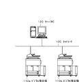
図1は、本実施形態を示す情報処理システムの構成を説明する図である。本例では、クライアントの情報処理装置としてMFP110a、110bを、サーバ装置の一例としてサーバPCを用いた場合を例に説明する。MFP110a、110bおよびサーバPC120は、ネットワーク100を介して通信可能である。ここで、MFP110a、110bは、所定のデータを処理するジョブを実行する。
FIG. 1 is a diagram for explaining the configuration of an information processing system according to the present embodiment. In this example, the MFPs 110a and 110b are used as information processing apparatuses of the client, and a server PC is used as an example of a server apparatus. The MFPs 110 a and 110 b and the server PC 120 can communicate via the
図1において、MFP110a、110bは、ユーザ操作やコピー/FAXなどの処理実行によってサーバPC120でMFP110a、110bの識別情報毎に対応づけ、かつ日時情報に対応づけてデータが管理されている。ここで、MFP110a、110bは、データに変更が発生した場合、その変更内容をサーバPC120へ送信して、データ更新を要求する。また、デジタル複合機110は、サーバPC120で管理するデータに更新があるかどうかを定期的、もしくは必要に応じて問い合わせ、更新されたデータがあれば取得して、デジタル複合機110内に保存する。
In FIG. 1, MFPs 110a and 110b are associated with each identification information of MFPs 110a and 110b in
例えばアドレス帳のFAX番号などのアドレスデータなど、サーバPC120で管理するデータをMFP110a、MFP110bでともに使用する場合、特定のジョブに使用される電話番号等のアドレスデータの同期処理は以下のように処理される。ここで、特定のジョブとは、原稿を読み取って上記電話番号に送信するようなFAXジョブが含まれる。
MFP110aでアドレスデータを部署移動や新規開設のため変更する必要が生じた場合、変更したアドレスデータがサーバPC120に通知されて、サーバPCで管理するアドレスデータが更新される。
その後、MFP110bからサーバPC120に対して更新の問い合わせが実行され、サーバPC120は先ほどのアドレスデータを更新データとしてMFP110bに送信する。MFP110bは、アドレスデータを受信したら、MFP110b内のアドレスデータを更新して保存する。
For example, when data managed by
When it is necessary to change the address data in the MFP 110a for departmental movement or new establishment, the changed address data is notified to the server PC 120, and the address data managed by the server PC is updated.
Thereafter, the MFP 110 b issues an update inquiry to the server PC 120, and the server PC 120 transmits the previous address data as update data to the MFP 110 b. When the MFP 110 b receives the address data, the MFP 110 b updates and stores the address data in the MFP 110 b.
本実施形態では、サーバ装置の一例としてサーバPC、クライアントの情報処理装置としてデジタル複合機を例に説明しているが、サーバ装置がデジタル複合機であっても良いし、クライアント装置がPCであっても良いのは言うまでも無い。また、本実施例では、同期されるデータとしてアドレスデータを例に説明しているが、他のデータであっても良いのも言うまでも無い。 In the present embodiment, the server PC is described as an example of the server apparatus, and the digital multifunction peripheral is described as an example of the information processing apparatus of the client. However, the server apparatus may be a digital multifunction peripheral, and the client apparatus is a PC. It goes without saying that it is good. Further, in the present embodiment, address data is described as an example of data to be synchronized, but it goes without saying that other data may be used.
図2は、図1に示したデジタル複合機110内の構成を示すブロック図である。
図2において、デジタル複合機110は、コントローラユニット200、操作部220、スキャナ230、プリンタ240を含んでいる。コントローラユニット200には、操作部220が接続されるとともに、画像入力デバイスであるスキャナ230や画像出力デバイスであるプリンタ240が接続される。
FIG. 2 is a block diagram showing the internal configuration of the digital multi-function peripheral 110 shown in FIG.
In FIG. 2, the digital multifunction peripheral 110 includes a
コントローラユニット200は、具体的には、CPU(Central Processing Unit)202を有する。CPU202は、ROM(Read Only Memory)206に格納されているブートプログラムによりOS(Operating System)を立ち上げる。コントローラユニット200は、このOS上で、HDD(Hard Disk Drive)205に格納されているアプリケーションプログラムを実行し、これによって各種処理を実行する。このCPU202の作業領域としてはRAM(Random Access Memory)203が用いられる。HDD205は、上記アプリケーションプログラムや各種データを格納する。
Specifically, the
CPU202には、システムバス210を介して、ROM206およびRAM203とともに、操作部I/F201、デバイスI/F204、Network207、画像処理208、外部シリアルI/F209が接続される。
An operation unit I /
操作部I/F201は、タッチパネルを有する操作部220とのインタフェースである。操作部I/F201は、操作部220に表示する各種データなどの情報を送出したり、ユーザにより入力された情報をCPU202に送出する。デバイスI/F204には、スキャナ230およびプリンタ240が接続され、データや制御信号の入出力が行われる。Network207は、ネットワーク100に接続され、ネットワーク100を介してネットワーク100上の各装置との間で情報の入出力を行う。画像処理208では、スキャナからの入力画像処理やプリンタへの出力画像処理、画像回転、画像圧縮、解像度変換、色空間変換、階調変換などの処理を行う。
The operation unit I /
図3は、図1に示したサーバPC120内の構成を示すブロック図である。
図3において、301は情報処理装置の演算・制御を司るCPUである。302はRAMであり、CPU301の主メモリとして、及び実行プログラムの領域や該プログラムの実行エリアならびにデータエリアとして機能する。303はCPU301の動作処理手順を記憶しているROMである。ROM303には情報処理装置の機器制御を行うシステムプログラムである基本ソフト(OS)を記録したプログラムROMと、システムを稼働するために必要な情報等が記録されているデータROMがある。また、ROM303の代わりに、後述のHDD309を用いる場合もある。
304はネットワークインターフェース(Network)であり、ネットワーク100を介してデジタル複合機(MFP)110a、110bとのデータ送受信等の通信を行う。305はVRAM(VideoVRAM)であり、情報処理装置のDisplay306の画面に表示させるための画像を展開し、その表示の制御を行う。306はディスプレイ等の表示装置(Display)である。
307は外部入力装置308からの入力信号を制御するためのコントローラ(KBC)である。308は利用者が行う操作を受け付けるための外部入力装置(KB)であり、例えばキーボードやマウス等のポインティングデバイスが用いられる。309はハードディスクドライブ(HDD)であり、アプリケーションプログラムや各種データ保存用に用いられる。300は上述した各ユニット間を接続するための伝送バス(アドレスバス、データバス、入出力バス、及び制御バス)である。
FIG. 3 is a block diagram showing an internal configuration of
In FIG. 3,
A
A controller (KBC) 307 controls an input signal from the
図4は、図1に示したMFP110a、110bで動作するデータ同期アプリケーションプログラムの構成を説明する図である。
図4において、データ同期アプリケーション400は、データ管理アプリケーション410などからの処理要求を受信する受付部401、処理の制御を行う制御部402、を備える。
さらに、データ同期アプリケーション400は、受付部401で受付けた要求をジョブとして管理するジョブ管理部403を備える。さらに、データ同期アプリケーション400は、Network207を介してサーバPC120とデータ通信を行う通信処理部404、MFP110a、110bの日時情報が変更されたことを検知する日時変更検知部405を備える。ジョブ管理部403で管理する情報は、HDD205やRAM203などに保存される。データ管理アプリケーション410は、操作部220に表示するデータを管理し、操作部220でユーザから入力されたデータを保持するとともに、データ同期アプリケーション400の受付部401にデータ更新内容を通知する。
FIG. 4 is a view for explaining the configuration of a data synchronization application program that operates in the MFPs 110a and 110b shown in FIG.
In FIG. 4, the
The
データ同期アプリケーション400およびデータ管理アプリケーション410は、RAM203、HDD205、ROM206のいずれかの記憶手段に記憶され、CPU202により実行される。
The
図5は、図1に示したサーバPC120で動作するデータ管理サーバアプリケーションプログラムの構成を説明する図である。
図5において、データ管理サーバアプリケーション500は、データ同期アプリケーション400などからの処理要求を受信したり結果を送信したりする送受信部501を備える。さらに、データ管理サーバアプリケーション500は、処理の制御を行う制御部502、送受信部501で受付けた要求を解析する解析部503を備える。
さらに、データ管理サーバアプリケーション500は、送受信部501で受付けた処理要求に応じてデータ管理部510とやり取りしてデータの作成/更新/削除/参照を実行するデータ処理部504を備える。データ管理部510で管理する情報は、HDD309やRAM302などに保存される。
データ管理サーバアプリケーション500およびデータ管理部510は、RAM302、HDD309、ROM303のいずれかの記憶手段に記憶され、CPU301により実行される。
FIG. 5 is a view for explaining the configuration of a data management server application program which operates on the
In FIG. 5, the data
The data
The data
MFP110a、110bは、本システムに参加する際に、サーバPC120に自装置の登録を行う。データ同期アプリケーション400の制御部402はMFP110a、110bの日時情報を特定して、通信処理部404から日時情報とともに登録要求を送信する。
When participating in the present system, the MFPs 110 a and 110 b register their own apparatuses in the
図6は、本実施形態を示す情報処理装置の制御方法を説明するフローチャートである。本例は、MFP110aからの登録要求を受信した際のサーバPC120で動作するデータ管理サーバアプリケーション500の処理に対応する。なお、各ステップは、サーバPC120のCPU301が記憶されたデータ管理サーバアプリケーション500を実行することで実現される。以下、データ管理サーバアプリケーション500を単にアプリケーション500と称する。また、以下の説明では、CPU301が実行するアプリケーション500の各モジュールを主体として説明する。
FIG. 6 is a flowchart for explaining the control method of the information processing apparatus showing the embodiment. This example corresponds to the processing of the data
S601で、送受信部501で各登録要求を受信したら、制御部502で要求受信時のサーバPC120での日時をRAM302上に保持しておく。S602では、送受信部501で受信した要求を解析部503で解析し、登録要求を行ったMFP110aの識別子情報を特定する。
ここで識別子情報とは、例えばMFP110aのシリアル番号などである。制御部502はデータ処理部504に登録処理を要求すると、S603では、データ処理部504は、データ管理部510に対して要求元のMFP110aが既に登録されていないかどうかを判断する。ここで既に登録されていると判断した場合には、MFP110aからの登録要求はエラーとなり、処理が終了する。
In step S601, when the transmission and
Here, the identifier information is, for example, the serial number of the MFP 110a. When the
MFP110aがデータ管理部510に登録されていないとデータ処理部504が判断した場合、S604に進み、データ処理部504はMFP110aをデータ管理部510に登録する。データ管理部510は、MFP110aの識別情報を取得する時間情報(後述する日時情報、以下日時情報と呼ぶ)に対応づけてHDD309に保存する。
S605では、データ処理部504は、MFP110aからの登録要求に含まれていたMFP110aの日時情報を特定する。S606では、S601で保持していたサーバPC120の日時情報と、S605で特定した日時情報を比較して、日時の差分値を算出する。S607では、データ処理部504は、S606で算出した差分情報の値(00:00:00)を、S604で登録したMFP110aの情報に関連付けて保存するようにデータ管理部510に要求する。データ管理部510は、差分情報の値(差分時間)を日時補正値として登録して、登録処理が終了となる。
If the
In step S605, the
図7は、図1に示したサーバPC120が管理する管理データを示す図である。本例は、MFP110aおよびMFP110bの登録処理完了後のデータ管理部510で管理されているデータ例である。この例では、MFP110aがサーバPC120よりも5分遅れた日時情報(−00:00:05)になっていて、MFP110bがサーバPC120よりも5分進んだ日時情報(00:00:05)になっている。
FIG. 7 is a view showing management data managed by the
次に、MFP110aとMFP110bでアドレス帳の同じデータを更新した場合の各処理をフローチャートとデータ例を用いて説明する。
図8は、本実施形態を示す画像形成装置の制御方法を説明するフローチャートである。本例は、図1に示したMFP110aとMFP110bでアドレス帳の同じアドレスデータ(管理情報)を更新する処理例である。なお、各ステップは、CPU202がHDD205等に記憶された制御プログラムを実行することで実現される。以下、図4に示したモジュールを主体として説明する。
図9は、図1に示したデータ変更前のMFP110a、MFP110b、サーバPC120に保持されているデータ例を示す図である。
Next, each process when the same data in the address book is updated in the MFP 110a and the MFP 110b will be described using a flowchart and a data example.
FIG. 8 is a flowchart for explaining a control method of the image forming apparatus showing the present embodiment. This example is a processing example of updating the same address data (management information) of the address book in the MFP 110a and the MFP 110b shown in FIG. Each step is realized by the
FIG. 9 is a view showing an example of data held in the MFP 110a, the MFP 110b, and the
最初にMFP110aでアドレスデータを変更した際の、データ同期アプリケーション400の処理を説明する。本実施形態では、アドレスが電話番号に対応する例であり、特定のメールアドレスや、URLでも同様に処理可能であることはいうまでもない。
操作部220で、ユーザが株式会社Aのアドレスを「03-2345-6789」に変更した場合、変更指示がデータ管理アプリケーション410に伝えられる。データ管理アプリケーション410は、データ同期アプリケーション400の受付部401にデータ変更内容を通知する。
First, processing of the
When the user changes the address of the corporation A to “03-2345-6789” on the
MFP110aにおいて、S901では、データ同期アプリケーション400の受付部401がデータ変更要求を受け付けた際のMFP110aの日時情報をRAM203に保持する。ここで、日時情報は「2014/04/23 11:00:00」であると想定する。S902では、受付部401で受付けた要求を制御部402がどのデータの変更なのかを特定する。S903では、制御部402がS901で保持していた日時情報とS902で特定した情報をもとに、ジョブ管理部403に同期ジョブとして登録要求する。ジョブ管理部403は、要求された情報を同期ジョブとしてHDD205に保存する。
In the MFP 110a, in S901, the
制御部402は、ジョブ管理部403の同期ジョブ保存が完了したら、受付部401で受けたデータ管理アプリケーション410からの要求に対して、受付完了を返す。S904では、制御部402がジョブ管理部403から同期ジョブを読み出して、日時情報とデータ変更内容に対応する更新すべき管理情報をサーバPC120に送信するよう、通信処理部404に要求する。通信処理部404は、要求された内容をサーバPC120に送信し、処理終了となる。
When the synchronous job storage of the
図10は、本実施形態を示すサーバ装置の制御方法を説明するフローチャートである。本例は、MFP110aからのアドレスデータ更新要求をサーバPC120のデータ管理サーバアプリケーション500が受信した際の処理例である。なお、各ステップは、サーバPC120のCPU301が記憶されたデータ管理サーバアプリケーション500を実行することで実現される。以下、データ管理サーバアプリケーション500を単にアプリケーション500と称する。また、以下の説明では、CPU301が実行するアプリケーション500の各モジュールを主体として説明する。
FIG. 10 is a flow chart for explaining the control method of the server apparatus showing the present embodiment. The present example is a processing example when the data
S1001で、送受信部501がMFP110aからのアドレスデータ更新要求に対応する同期ジョブを受信したら制御部502に通知し、制御部502が受信した内容を解析部503に渡して解析し、要求元のMFP110aを特定する。ここで要求元が特定できない場合、図示しないが本処理はエラー終了となる。
S1002では、制御部502が解析部503から要求内容を取得して、前記同期ジョブがデータ更新要求かどうかを判断する。データ更新要求であると制御部502が判断した場合、S1003では、制御部502がMFP110aの日時補正値「-00:05:00」をデータ管理部510から取得する。なお、詳細は後述するが、同期ジョブの要求がデータ取得要求かどうかはS1011で判断され、同期ジョブが日時補正要求かどうかはS1012で判断される。そして、対応するデータ取得要求処理がS1013で、対応する日時補正値更新処理がS1014で実行される。
When the transmission /
In step S1002, the
S1004では、制御部502が解析部503から受信した内容の日時情報「2014/04/23 11:00:00」を取得する。S1005では、制御部502がS1004で取得した日時情報を、S1003で取得した日時補正値で補正して、更新データの日時情報「2014/04/23 10:55:00」を求める。S1006では、制御部502が解析部503から更新対象のデータ内容を取得して、データ処理部504にデータ内容とS1005で求めた補正後の日時情報「2014/04/23 10:55:00」を渡す。データ処理部504は、更新対象のデータの最終更新日時「2014/4/23 10:00:00」をデータ管理部510から取得する。
In S1004, the
S1007では、データ処理部504が、S1006で取得したアドレスデータの最終更新日時情報と、S1005で求めた補正後の日時情報を比較して、更新要求が保持していたアドレスデータよりも新しい日時の更新要求であるかどうかを判断する。ここで新しいとデータ処理部504が判断した場合には、S1008で、データ処理部504が、データ管理部510に対して更新対象のアドレスデータを要求された値で更新する要求を行う。すると、データ管理部510は、保持している管理情報に含まれるアドレスデータを更新する。
一方、S1007で、アドレスデータが新しいとデータ処理部504が判断しない場合には、S1009で、S1001で特定されたMFP110aから受信した同期ジョブに対応する要求を破棄して、S1010へ進む。
この際、データ処理部504が更新されたアドレスデータの最終更新日時をS1005で求めた補正後の日時情報「2014/04/23 10:55:00」で、データ更新日時を処理実行時の日時情報(例えば「2014/04/23 10:55:10」)でそれぞれ更新する。更新が完了したら、S1010で、送受信部501から更新完了を要求元に応答を返信して処理完了となる。なお、当該応答を要求元のMFP110a、MFP110bが所定時間内に受信していないと判断した場合、MFP110a、MFP110bがネットワークに接続されていないと判断することができる。
In S1007, the
On the other hand, if the
At this time, with the date and time information after correction “2014/04/23 10:55:00” obtained in S1005, the last updated date and time of the address data updated by the
次に、MFP110aで更新した後、MFP110bで、同じく株式会社Aのアドレスをさらに「03-3456-7890」に更新した場合を説明する。
MFP110bの時計で「2014/04/23 10:54:00」での更新要求であるものとする。図10に示すS1001で、送受信部501がMFP110aからのアドレスデータ更新要求を受信したら制御部502に通知し、制御部502が受信した内容を解析部503に渡して解析し、要求元のMFP110bを特定する。
Next, a case where the address of the corporation A is similarly updated to “03-3456-7890” in the MFP 110 b after the update in the MFP 110 a will be described.
It is assumed that the clock of the MFP 110 b is an update request at “2014/04/23 10:54:00”. When the transmission /
S1002で、制御部502が解析部503から要求内容を取得して、データ更新要求であると判断し、S1003では、制御部502がMFP110bの日時補正値「00:05:00」をデータ管理部510から取得する。S1004では、制御部502が解析部503から受信した内容の日時情報「2014/04/23 10:54:00」を取得する。S1005では、制御部502がS1004で取得した日時情報を、S1003で取得した日時補正値で補正して、更新データの日時情報「2014/04/23 10:59:00」を求める。
In step S1002, the
S1006では、制御部502が解析部503から更新対象のデータ内容を取得して、データ処理部504にデータ内容とS1005で求めた補正後の日時情報「2014/04/23 10:59:00」を渡す。データ処理部504は更新対象のアドレスデータの最終更新日時「2014/4/23 10:55:00」をデータ管理部510から取得する。S1007では、データ処理部504が、S1006で取得したアドレスデータの最終更新日時と、S1005で求めた補正後の日時情報を比較して、更新要求が保持していたアドレスデータよりも新しいと判断する。S1008で、データ処理部504が、データ管理部510に対して更新対象のアドレスデータを要求された値で更新する要求を行い、データ管理部510は、保持しているアドレスデータを更新する。
In S1006, the
この際、更新されたアドレスデータの最終更新日時をS1005で求めた補正後の日時情報「2014/04/23 10:59:00」で、データ更新日時を処理実行時の日時情報(例えば「2014/04/23 10:59:10」)でそれぞれ更新する。更新が完了したら、S1010で、送受信部501から更新完了を要求元に返信して処理完了となる。
At this time, with the date and time information “2014/04/23 10:59:00” after correction obtained in S1005, the last updated date and time of the updated address data, the date and time information at the time of processing the data update date (for example Update each on 04/23 10:59:10 "). When the update is completed, the transmission /
この処理が完了したときのMFP110aおよびMFP110bのデータ管理アプリケーション410、サーバPC120のデータ管理部510にそれぞれ保持されているアドレスデータを図11に示す。
FIG. 11 shows the address data held by the
次に、デジタル複合機110がサーバPC120から最新データを取得する処理について、図8および図12のフローチャートを用いて説明する。
デジタル複合機110からサーバPC120に対して最新データ取得要求を行う場合、デジタル複合機110に保持されている最終データ取得日時情報を付与してデータ取得要求が実行される。データ管理サーバアプリケーション500の送受信部501が要求を受信した場合、S1001で要求元を特定する。そして、S1011でデータ取得要求であると判断されてデータ取得要求処理が実行される。
Next, a process in which the digital multi-functional peripheral 110 acquires the latest data from the
When the digital multi-functional peripheral 110 sends a latest data acquisition request to the
図12は、本実施形態を示すサーバ装置の制御方法を説明するフローチャートである。なお、各ステップは、サーバPC120のCPU301が記憶されたデータ管理サーバアプリケーション500を実行することで実現される。以下、データ管理サーバアプリケーション500を単にアプリケーション500と称する。また、以下の説明では、CPU301が実行するアプリケーション500の各モジュールを主体として説明する。
S1201で、制御部502が受信した内容を解析部503に渡して、データ取得の対象がアドレスデータであることを特定する。S1202では、制御部502が解析部503から要求に含まれていた最終データ取得日時情報を特定し、データ処理部504にアドレスデータであることと、最終データ取得日時情報を渡す。S1203では、データ処理部504がデータ管理部510にアドレスデータで最終データ取得日時情報の日時情報以降に更新されたアドレスデータが存在するか確認する。
FIG. 12 is a flow chart for explaining the control method of the server apparatus showing the present embodiment. Each step is realized by executing the data
In step S1201, the content received by the
データ管理部510では、管理しているアドレスデータのデータ更新日時が、最終データ取得日時情報の日時以降のデータを特定する。ここで、データ管理部510から1件以上のアドレスデータが返却された場合、S1204に進み、返却されたアドレスデータと実行時の日時情報を要求元に返信する。
S1203でアドレスデータが無いとデータ処理部504が判断した場合には、実行時の日時情報のみを要求元に返信する。例えばMFP110aからのデータ取得要求の場合、最終データ取得日時情報「2014/4/23 10:00:00」がデータ取得要求に含まれている。データ管理部510は、この「2014/4/23 10:00:00」よりも新しいデータ更新日時の情報を検索する。株式会社Aのアドレスデータのデータ更新日時が「2014/04/23 10:59:10」であるので、データ取得要求に対して、このアドレスデータが返信される。
The
If the
例えば、S1203の処理実行時間が「2014/4/23 11:00:00」である場合、処理完了後のMFP110aのデータ管理アプリケーション410が保持するアドレスデータは、図13のようになる。さらに、MFP110bも同様のデータ取得処理を実行し、そのときのS1203の処理実行時間が「2014/4/23 11:00:10」である場合、MFP110bのデータ管理アプリケーション410が保持するアドレスデータは図13に示すようになる。
For example, when the processing execution time of S1203 is "2014/4/23 11:00:00", the address data held by the
図14は、本実施形態を示す画像形成装置の制御方法を説明するフローチャートである。本例は、MFP110aのデータ同期アプリケーション400が時計を変更して、5分戻した場合に実行される処理例である。なお、各ステップは、CPU202がHDD205等に記憶された制御プログラムを実行することで実現される。以下、図4に示したモジュールを主体として説明する。
S1401では、日時変更検知部405が、デジタル複合機110の日時が変更されたかどうかを判断する。日時変更検知部405が日時の変更を検知すると、S1402に進み、制御部402が変更後の日時情報「2014/04/23 11:00:00」を特定する。S1403にて、通信処理部404が変更後の日時情報をサーバPC120へ日時変更要求として送信する。
FIG. 14 is a flowchart for describing a control method of the image forming apparatus showing the present embodiment. This example is an example of processing executed when the
In S1401, the date and time
MFP110aからの日時変更要求をサーバPC120のデータ管理サーバアプリケーション500が受信した際の処理を図10と図15のフローチャートを用いて説明する。
図15は、本実施形態を示すサーバ装置の制御方法を説明するフローチャートである。なお、各ステップは、サーバPC120のCPU301が記憶されたデータ管理サーバアプリケーション500を実行することで実現される。以下、データ管理サーバアプリケーション500を単にアプリケーション500と称する。また、以下の説明では、CPU301が実行するアプリケーション500の各モジュールを主体として説明する。
送受信部501がMFP110aからの要求を受信したら、S1001で、要求元がMFP110aであることを特定する。制御部502は解析部503の結果から、S1002、S1011、S1012と進み、S1012で日時補正要求であると判断して、S1013に対応する日時補正値更新処理へ進む。日時補正値更新処理は、S1501で、制御部502が要求受信時のサーバPC120の日時情報(例えば「2014/04/23 11:00:10」)を特定する
A process when the data
FIG. 15 is a flow chart for explaining the control method of the server apparatus showing the present embodiment. Each step is realized by executing the data
When the transmission /
S1502では、制御部502が解析部503の解析結果から要求に含まれる日時情報「2014/04/23 11:00:00」を特定する。S1503では、制御部502がS1501とS1502で特定した日時情報から日時補正値「00:00:10」を求め、S1001で特定した情報とともにデータ処理部504に日時補正を依頼する。S1504では、データ処理部504がMFP110aの日時補正値を「00:00:10」に更新するようデータ管理部510に依頼し、データ管理部510が日時補正値を更新する。処理実行後のデータ管理部510が管理する情報は図16に示すように更新される。
In S1502, the
以上説明したように、日時設定の異なるMFP110aとMFP110bから同じアドレスデータに対してアドレスデータの更新処理が要求された場合でも、サーバPC120で正しくアドレスデータを更新する。これにより、デジタル複合機110aは更新したアドレスデータを取得して、更新されたアドレスデータと同期することが可能となる。
さらに、途中でデジタル複合機110a、110bの日時が操作部220からの入力に基づいて変更された場合も、変更時にサーバPC120での日時補正値を更新することで、正しい補正値を用いて処理を行うことが可能となる。
As described above, even when address data update processing is requested for the same address data from the MFP 110a and MFP 110b having different date and time settings, the
Furthermore, even if the date and time of the digital multi-functional peripheral 110a and 110b is changed based on the input from the
〔第2実施形態〕
本実施形態では、MFP110aがネットワークに接続できていない場合のサーバ装置による同期処理について説明を行う。なお、ネットワークに接続できないとは、MFP110aが接続するLAN上でなんらかの障害が発生した後、ネットワークが復旧した場合を想定する。
デジタル複合機110およびサーバPC120の管理データは、第1実施形態の初期状態と同じように図7、図9で示す値であるとする。第1実施形態で説明した各処理において、MFP110aがネットワーク100に接続できていないため、サーバPC120へ更新要求を行えなかった時刻を基準として、一定時間経過後にネットワーク100に接続し、処理を再開した場合の処理を説明する。ただし、図7に示すとおり、MFP110aはシステムには参加できていて、参加した後、ネットワーク100に接続できていない状態である。なお、上記一定時間は、図示しない時計手段(タイマ)により通信接続できない日時から通信接続を再開した日時を測定し、その差分から経過時間を算出することが可能に構成されている。
Second Embodiment
In the present embodiment, synchronization processing by the server apparatus when the MFP 110a can not be connected to the network will be described. Note that the inability to connect to the network is assumed to be the case where the network is restored after some failure occurs on the LAN to which the MFP 110a is connected.
It is assumed that the management data of the digital multi-function peripheral 110 and the
まず、MFP110aから株式会社Aのアドレスを「03-2345-6789」をMFP110aの日時で「2014/04/23 11:00:00」に更新した場合について、説明する。データ同期アプリケーション400は、図8のフローチャートを用いて説明したとおり、S903でデータ更新内容をジョブ管理部403に保持する。S904で、日時と変更内容をサーバPC120に送信する処理においてエラーとなった場合、制御部402は、一定時間経過後にジョブ管理部403から情報と取り出して、再度S904の処理を実行する。制御部402は、S904の処理が成功するまで、一定間隔で処理を繰り返す。
First, a case where the address of the corporation A from the MFP 110a is updated to "2014/04/23 11:00:00" on the date and time of the MFP 110a will be described. The
MFP110bでのデータ更新要求は、第1実施形態で説明したように処理されるため、MFP110a、MFP110b、サーバPC120で管理されるアドレスデータは図17に示すようになる。
Since the data update request in the MFP 110b is processed as described in the first embodiment, the address data managed by the MFP 110a, the MFP 110b, and the
MFP110aのネットワークが「2014/04/23 11:30:00」に復旧し、S904の処理が成功した場合の、データ管理サーバアプリケーション500の処理を図10のフローチャートを用いて説明する。第1実施形態で説明したのと同様、S1001で、制御部502が要求元はMFP110aであることを特定する。S1002でデータ更新要求であると判断し、S1003で、制御部502がMFP110aの日時補正値「‐00:05:00」をデータ管理部510から取得する。テップS1004では、制御部502が解析部503から受信した内容の日時情報「2014/04/23 11:00:00」を取得する。
The process of the data
S1005では、制御部502がS1004で取得した日時情報を、S1003で取得した日時補正値で補正して、更新データの日時情報「2014/04/23 10:55:00」を求める。
S1006では、制御部502が解析部503から更新対象のデータ内容を取得して、データ処理部504にデータ内容とS1005で求めた補正後の日時情報「2014/04/23 10:55:00」を渡す。データ処理部504は更新対象のアドレスデータの最終更新日時「2014/4/23 10:59:00」をデータ管理部510から取得する。S1007では、データ処理部504が、S1006で取得したアドレスデータの最終更新日時と、S1005で求めた補正後の日時情報を比較して、更新要求が保持していたアドレスデータよりも新しい日時の更新要求であるかどうかを判断する。ここで、新しくないと判断されてS1009に進む。
S1009では、データ処理部504が制御部502から依頼された要求内容を破棄する。そして、S1010で、送受信部501から更新完了を要求元に返信して処理完了となる。
In S1005, the
In S1006, the
In S1009, the
以上説明したように、データ管理部510で管理するアドレスデータは更新されずに、図17のままとなり、MFP110aからのデータ更新要求が、後から要求されたとしても正しく処理を行うことが可能である。
As described above, the address data managed by the
次に、MFP110aの時計を変更して、5分戻した場合に実行される処理について説明する。S1401で、日時変更検知部405が、MFP110aの日時が変更されたことを検知すると、S1402で、制御部402が変更後の日時情報「2014/04/23 11:00:00」を特定する。S1403で、通信処理部404が変更後の日時情報をサーバPC120へ送信する処理において、エラーになった場合、S1404で失敗と判断されて日時情報の再送処理(S1405)が実行される。
Next, processing performed when the clock of the MFP 110 a is changed and returned five minutes will be described. If the date / time
図18は、本実施形態を示す画像形成装置の制御方法を説明するフローチャートである。本例は画像形成装置における日時情報の再送処理例である。なお、各ステップは、CPU202がHDD205等に記憶された制御プログラムを実行することで実現される。以下、図4に示したモジュールを主体として説明する。
S1801で、制御部402は、MFP110aの現在日時「2014/04/23 11:00:00」を特定して、RAM203もしくはHDD205に保持する。S1802では、制御部402が一定時間経過後に、S1801で保持していた日時からの経過時間(例えば「00:01:00」)を測定する。S1803では、通信処理部404が、変更後の日時情報にS1802で求めた経過情報を追加して、サーバPC120へ日時変更要求として送信する。S1804で、制御部402が送信に失敗したと判断した場合には、S1802に戻って、一定時間経過後に経過時間を再度求める(例えば「00:02:00」)。送信に成功したら、日時情報の再送処理終了となる。
FIG. 18 is a flow chart for explaining a control method of the image forming apparatus showing the present embodiment. This example is an example of retransmission processing of date and time information in an image forming apparatus. Each step is realized by the
In step S1801, the
次に、日時情報の再送処理による日時変更要求を、サーバPC120が受信したときのデータ管理サーバアプリケーション500の処理を説明する。MFP110aが1分後の再送処理で成功した場合で説明する。図15のフローチャートで、S1501までは第1実施形態と同様の処理が実行される。S1501で制御部502が保持する日時は第1実施形態のときの1分後になるので「2014/04/23 11:01:10」となる。
Next, processing of the data
S1502では、制御部502が解析部503の解析結果から要求に含まれる日時情報「2014/04/23 11:00:00」と経過時間「00:01:00」を特定する。さらに、制御部502は、上記日時情報に経過時間を足して日時情報「2014/04/23 11:01:00」を特定する。S1503では、制御部502が、S1501とS1502で特定した日時情報から日時補正値「00:00:10」を求め、S1001で特定した情報とともにデータ処理部504に日時補正を依頼する。
以上説明したように、MFP110aでの日時変更時にサーバPC120に変更後の日時情報を送信できなかったとしても、正しく日時補正値の更新処理を行える。
In S1502, the
As described above, even if the post-change date and time information can not be transmitted to the
次に、ネットワーク100に接続できていないときに、MFP110aから株式会社Aのアドレスを「03-2345-6789」をMFP110aの日時で「2014/04/23 11:00:00」に更新する。そして、その5分後に、MFP110aの時計を5分戻し、変更後のMFP110aの日時で「2014/04/23 11:15:00」に株式会社Aのアドレスを「03-4567-8901」に変更する。その後、MFP110aの日時で「2014/04/23 11:30:00」にネットワーク100に接続する場合について説明する。
Next, when connection to the
MFP110aのデータ同期アプリケーション400は、ジョブ管理部403に「2014/04/23 11:00:00」に「03-2345-6789」に更新したジョブが保存される。次に日時変更検知部405が、MFP110aの日時が変更されたことを検知し、変更後の日時情報「2014/04/23 11:00:00」と、S1801で特定した現在日時「2014/04/23 11:00:00」を制御部402が保持する。そして、MFP110aのデータ同期アプリケーション400は、S903として、新たにジョブ管理部403に「2014/04/23 11:15:00」に「03-4567-8901」に更新したジョブを保存する。ここで、ジョブ管理部403には、まだサーバPC120に送信が完了していないジョブが存在するため、制御部402は、S904の処理は行わずに、先に保存されていた更新ジョブのS904の処理を実行する。
In the
MFP110aはネットワーク100に復帰した場合、先に保存されていた「2014/04/23 11:00:00」に「03-2345-6789」に更新したジョブをサーバPC120に送信する。送信が完了したら、制御部402は後でジョブ管理部403に保存していた「2014/04/23 11:15:00」に「03-4567-8901」に更新したジョブの送信処理を実施する前に、日時情報の再送処理を実行する。
このとき、S1803では、変更後の日時情報「2014/04/23 11:00:00」と経過時間「00:30:00」をサーバPC120に送信する。日時情報の再送処理に成功したら、制御部402は、ジョブ管理部403に保存していた「2014/04/23 11:15:00」に「03-4567-8901」に更新したジョブの送信処理を実行する。
When the MFP 110a returns to the
At this time, in S1803, the post-change date and time information “2014/04/23 11:00:00” and the elapsed time “00:30:00” are transmitted to the
これらの要求をサーバPC120のデータ管理サーバアプリケーション500が受信した場合の処理について説明する。最初のアドレスデータ更新要求を受けると、先ほど説明したとおり、更新要求は破棄されて処理が終了する。次に日時補正値の更新処理が実行され、S1501で制御部502が保持する日時は「2014/04/23 11:30:10」となる。
A process when the data
S1502で、制御部502が解析部503の解析結果から要求に含まれる日時情報「2014/04/23 11:00:00」と経過時間「00:30:00」を特定し、日時情報「2014/04/23 11:30:00」を特定する。S1503で制御部502が求める日時補正値は「00:00:10」となる。最後に、アドレスデータ更新要求「2014/04/23 11:15:00」「03-4567-8901」を送受信部501が受信した場合、S1003で制御部502が日時補正値「00:00:10」を取得する。S1005で制御部502がアドレスデータ更新要求のアドレスデータを「2014/04/23 11:15:10」に補正する。これにより、アドレスデータは、最終更新日時「2014/04/23 10:59:00」より新しいため、データ処理部504がデータ管理部510で管理するアドレスデータを「03-4567-8901」に更新する。
In step S1502, the
以上説明したように、サーバPC120との通信が行えないときに日時変更が実施された場合には、日時変更より前の更新ジョブを先行して実施した後、日時補正値更新処理を行ってから、後続する日時変更後の更新ジョブの処理を行う。これにより、正しくアドレスデータの更新を実施することができる。
As described above, when the date and time change is performed when communication with
〔第3実施形態〕
上記第3実施形態では、MFP110aで複数の関連するデータを更新した場合の処理について説明を行う。なお、ここで複数の関連するデータとは、後述するような複数の設定であって、いずれかの設定をオンからオフ、オフからオンに設定した場合、MFP110aとMFP110bとで設定が相互に整合するようにすべき設定である場合を説明する。
Third Embodiment
In the third embodiment, processing in the case where a plurality of related data are updated in the MFP 110a will be described. Here, the plurality of related data are a plurality of settings as described later, and when any setting is set from on to off and from off to on, the settings are mutually consistent between MFP 110 a and MFP 110 b. The case where the setting should be made will be described.
MFP110aおよびMFP110bのデータ管理アプリケーション410、サーバPC120のデータ管理部510で、図19に示すデータが保存されている。ここでKey「認証を行う」とKey「パーソナライズ設定を利用する」には関連があり、「認証を行う」がOFFの場合には、「パーソナライズ設定を利用する」もOFFにする必要がある。サーバPC120に保持されている日時補正値は図7の状態であるとする。
Data shown in FIG. 19 are stored in the
第2実施形態で説明した場合と同様、MFP110aがネットワーク100に接続できていないときに、MFP110aで「認証を行う」がOFFに更新され、データ管理アプリケーション410は、合わせて「パーソナライズ設定を利用する」OFFに更新する。
データ管理アプリケーション410は、データ同期アプリケーション400の受付部401に「認証を行う」OFFと「パーソナライズ設定を利用する」OFFを依頼する。データ同期アプリケーション400は要求受付時の日時「2014/04/23 11:05:00」と変更内容をジョブとしてジョブ管理部403に保持する。
As in the case described in the second embodiment, when the MFP 110a can not connect to the
The
次にMFP110bで、「パーソナライズ設定を利用する」をOFFに更新する。MFP110bの日時「2014/04/23 11:10:00」に更新を行い、サーバPC120で管理されるデータが更新される。さらにMFP110bで「2014/04/23 11:15:00」に再び「パーソナライズ設定を利用する」をONに更新する。そして、MFP110bはサーバPC120にデータ取得要求を行い、最新のデータを取得する。ここまでの処理が実行されると、デジタル複合機110とサーバPC120で管理する組み合わせ管理情報に対応する各データ(Key、Value)は、図20の状態に更新される。
Next, “use personalization setting” is updated to OFF in the MFP 110 b. The date and time "2014/04/23 11: 10:00" of the MFP 110b is updated, and the data managed by the
次に、MFP110aがネットワーク100に接続し、ジョブ管理部403が保持していた処理を実行した場合について説明する。MFP110aは、「2014/04/23 11:05:00」に「認証を行う」を「OFF」とし、さらに、「パーソナライズ設定を利用する」を「OFF」にした旨をサーバPC120に送信する。サーバPC120のデータ管理サーバアプリケーション500は、要求元を特定して、MFP110aの日時補正値「-00:05:00」を取得する。
S1004で、制御部502が受信した内容の日時情報「2014/04/23 11:05:00」を取得し、S1005で、制御部502が日時補正値で補正して、日時情報「2014/04/23 11:00:00」を求める。S1006では、制御部502が解析部503から更新対象のデータ内容を取得して、データ処理部504にデータ内容とS1005で求めた補正後の日時情報「2014/04/23 11:00:00」を渡す。データ処理部504は更新対象の「認証を行う」の最終更新日時「2014/4/23 10:00:00」と「パーソナライズ設定を利用する」の最終更新日時「2014/4/23 11:20:00」をデータ管理部510から取得する。
Next, a case where the MFP 110 a is connected to the
In S1004, the
終更新日時を比較して更新要求が保持していた組み合わせの管理情報に対応する各データよりも新しい日時かどうかを判断する。ここで、「認証を行う」は新しいと判断され、「パーソナライズ設定を利用する」は古いと判断される。しかし、データ処理部504は、「認証を行う」を「OFF」に更新する場合には「パーソナライズ設定を利用する」も「OFF」にする必要があると当該データの属性から判断する。このため、データ処理部504は、「、「パーソナライズ設定を利用する」も「OFF」で更新をデータ管理部510に要求する。
データ管理部510は要求されたデータの更新を行い、データ更新日時を処理実行時の日時(例えば「2014/4/23 11:30:00」)に更新して、送受信部501が更新完了を要求元に返信して処理完了となる。この後、MFP110aとMFP110bがデータ取得要求処理を行い、最終的にデジタル複合機110とサーバPC120で管理される組み合わせの管理情報に対応する各データは図21に示すようになる。
The final update date and time are compared to determine whether it is a date and time newer than each data corresponding to the management information of the combination held by the update request. Here, "perform authentication" is determined to be new, and "use personalization settings" is determined to be old. However, when updating “perform authentication” to “OFF”, the
The
以上説明したように、組み合わせの管理情報に対応する各データを更新する場合には、各データ毎に更新日時を確認するだけではなく、各データの関連も考慮してデータ更新の判断を行う。これにより、正しく組み合わせの管理情報に対応する各データの更新を実行することができる。 As described above, when each data corresponding to the combination management information is updated, not only the update date and time is checked for each data, but also the data update is determined in consideration of the relation of each data. In this way, it is possible to correctly update each data corresponding to the combination management information.
本発明の各工程は、ネットワーク又は各種記憶媒体を介して取得したソフトウエア(プログラム)をパソコン(コンピュータ)等の処理装置(CPU、プロセッサ)にて実行することでも実現できる。 Each process of the present invention can also be realized by executing software (program) acquired via a network or various storage media with a processing device (CPU, processor) such as a personal computer (computer).
本発明は上記実施形態に限定されるものではなく、本発明の趣旨に基づき種々の変形(各実施形態の有機的な組合せを含む)が可能であり、それらを本発明の範囲から除外するものではない。 The present invention is not limited to the above embodiments, and various modifications (including organic combinations of the respective embodiments) are possible based on the spirit of the present invention, which are excluded from the scope of the present invention is not.
120 サーバPC
110a、110b デジタル複写機
120 server PC
110a, 110b Digital copier
Claims (8)
各情報処理装置から、前記情報処理装置の日時情報を含む登録要求を受信する第1受信手段と、
前記登録要求を受信することに応じて、受信した各情報処理装置の日時情報と前記サーバ装置が管理する日時情報との差分時間をそれぞれ算出する算出手段と、
前記算出手段がそれぞれ算出した各情報処理装置との差分時間を各情報処理装置に対応づけて保持手段に登録する登録手段と、
各情報処理装置によって取得されるべき設定情報を、前記設定情報が更新された日時を示す第1の日時情報と関連付けて格納する格納手段と、
前記情報処理装置から、前記情報処理装置に格納された設定情報の更新内容を示す更新情報と、第1の更新日時情報を受信する第2受信手段と、
前記第1の日時情報と、前記第1の更新日時情報と、前記差分時間とに基づいて、前記受信した更新情報によって、前記格納手段に格納されている設定情報を更新するかどうかを制御する第1制御手段と、
を備えることを特徴とするサーバ装置。 A server device that communicates with a plurality of information processing devices, and
A first receiving unit configured to receive a registration request including date and time information of the information processing apparatus from each information processing apparatus;
Calculating means for calculating a difference time between the received date and time information of each information processing apparatus and the received date and time information managed by the server apparatus according to receiving the registration request ;
Registration means for associating the time difference with each information processing apparatus calculated by the calculation means with each information processing apparatus and registering the difference time in the holding means;
Storage means for storing setting information to be acquired by each information processing apparatus in association with first date and time information indicating a date and time when the setting information is updated;
Update information indicating update content of setting information stored in the information processing apparatus from the information processing apparatus; and second receiving means for receiving first update date and time information;
It is controlled based on the first date and time information, the first update date and time information, and the difference time whether or not the setting information stored in the storage unit is updated by the received update information. First control means,
A server apparatus comprising:
前記第3受信手段が受信した日時情報を用いて、前記保持手段に登録されている差分時間を更新する更新手段を有することを特徴とする請求項1又は請求項2に記載のサーバ装置。 The server apparatus according to claim 1 or 2, further comprising an update unit configured to update the difference time registered in the holding unit using the date and time information received by the third reception unit.
前記最終取得日時情報に基づいて、前記情報処理装置に、前記格納手段に格納されている設定情報を送信するかどうかを制御する第2制御手段を有することを特徴とする請求項1乃至3の何れか1項に記載のサーバ装置。4. The apparatus according to claim 1, further comprising second control means for controlling whether or not the setting information stored in the storage means is transmitted to the information processing apparatus based on the final acquisition date and time information. The server apparatus according to any one of the above.
他のデータも変更すべきであると判断した場合、受信する日時情報を登録されたそれぞれの差分時間で補正した日時情報を用いて管理手段が管理する所定のデータおよび前記他のデータを更新する更新手段を有することを特徴とすることを特徴とする請求項1記載のサーバ装置。 When a data update request for the first data is received from each information processing apparatus together with date and time information, a second determination is made as to whether or not the second data managed according to the attribute of the first data should be changed Means,
If it is determined that other data should also be changed, the predetermined data managed by the management means and the other data are updated using the date and time information corrected with each registered differential time and date information to be received The server apparatus according to claim 1, further comprising an updating unit.
各情報処理装置から、前記情報処理装置の日時情報を含む登録要求を受信する第1受信工程と、
前記登録要求を受信することに応じて、受信した各情報処理装置の日時情報と前記サーバ装置が管理する日時情報との差分時間をそれぞれ算出する算出工程と、
前記算出工程でそれぞれ算出した各情報処理装置との差分時間を各情報処理装置に対応づけて保持手段に登録する登録工程と、
各情報処理装置によって取得されるべき設定情報を、前記設定情報が更新された日時を示す第1の日時情報と関連付けて格納する格納工程と、
前記情報処理装置から、前記情報処理装置に格納された設定情報の更新内容を示す更新情報と、第1の更新日時情報を受信する第2受信工程と、
前記第1の日時情報と、前記第1の更新日時情報と、前記差分時間とに基づいて、前記受信した更新情報によって、前記格納工程で格納された設定情報を更新するかどうかを制御する第1制御手段と、
を備えることを特徴とするサーバ装置の制御方法。 A control method of a server apparatus that communicates with a plurality of information processing apparatuses,
A first receiving step of receiving a registration request including date and time information of the information processing apparatus from each information processing apparatus;
A calculation step of calculating a difference time between the received date and time information of each information processing apparatus and the received date and time information managed by the server apparatus according to receiving the registration request ;
A registration step of associating the time difference with each information processing device calculated in the calculation step with each information processing device and registering the difference time in the holding means;
A storage step of storing setting information to be acquired by each information processing apparatus in association with first date and time information indicating a date and time when the setting information is updated;
Update information indicating update contents of setting information stored in the information processing apparatus from the information processing apparatus; and a second receiving step of receiving first update date and time information;
It is controlled whether the setting information stored in the storing step is updated by the received update information based on the first date and time information, the first update date and time information, and the difference time. 1 control means,
A control method of a server apparatus comprising:
Priority Applications (3)
| Application Number | Priority Date | Filing Date | Title |
|---|---|---|---|
| JP2014152984A JP6508894B2 (en) | 2014-07-28 | 2014-07-28 | Server apparatus, control method of server apparatus and program |
| US14/806,060 US9544459B2 (en) | 2014-07-28 | 2015-07-22 | Information processing apparatus, image forming apparatus, information processing system, method for controlling information processing apparatus, method for controlling image forming apparatus, and storage medium storing program |
| US15/371,626 US10200556B2 (en) | 2014-07-28 | 2016-12-07 | Information processing apparatus, image forming apparatus, information processing system, method for controlling information processing apparatus, method for controlling image forming apparatus, and storage medium storing program |
Applications Claiming Priority (1)
| Application Number | Priority Date | Filing Date | Title |
|---|---|---|---|
| JP2014152984A JP6508894B2 (en) | 2014-07-28 | 2014-07-28 | Server apparatus, control method of server apparatus and program |
Publications (3)
| Publication Number | Publication Date |
|---|---|
| JP2016031593A JP2016031593A (en) | 2016-03-07 |
| JP2016031593A5 JP2016031593A5 (en) | 2017-09-07 |
| JP6508894B2 true JP6508894B2 (en) | 2019-05-08 |
Family
ID=55167696
Family Applications (1)
| Application Number | Title | Priority Date | Filing Date |
|---|---|---|---|
| JP2014152984A Active JP6508894B2 (en) | 2014-07-28 | 2014-07-28 | Server apparatus, control method of server apparatus and program |
Country Status (2)
| Country | Link |
|---|---|
| US (2) | US9544459B2 (en) |
| JP (1) | JP6508894B2 (en) |
Families Citing this family (4)
| Publication number | Priority date | Publication date | Assignee | Title |
|---|---|---|---|---|
| JP2017156819A (en) * | 2016-02-29 | 2017-09-07 | キヤノン株式会社 | Management system, substitution management unit, management method, and program |
| JP6769080B2 (en) * | 2016-04-14 | 2020-10-14 | 株式会社リコー | Information equipment, programs and communication management methods |
| JP2022167508A (en) * | 2021-04-23 | 2022-11-04 | 京セラドキュメントソリューションズ株式会社 | Information processing apparatus, setting tool program, and information processing system |
| JP2024043890A (en) * | 2022-09-20 | 2024-04-02 | セイコーエプソン株式会社 | Printing system, control method for printing system, and information processing apparatus |
Family Cites Families (14)
| Publication number | Priority date | Publication date | Assignee | Title |
|---|---|---|---|---|
| JPH11161441A (en) * | 1997-11-27 | 1999-06-18 | Fuji Xerox Co Ltd | Printer |
| GB0128243D0 (en) * | 2001-11-26 | 2002-01-16 | Cognima Ltd | Cognima patent |
| TWI256556B (en) * | 2002-07-08 | 2006-06-11 | Via Tech Inc | Distributed concurrent version management system and method |
| JP4276920B2 (en) | 2003-10-07 | 2009-06-10 | オリンパス株式会社 | Information processing program, storage medium, information processing apparatus, and information processing method |
| US8495202B2 (en) * | 2003-10-24 | 2013-07-23 | Brother Kogyo Kabushiki Kaisha | Imaging device information management system |
| US20080091065A1 (en) * | 2006-10-04 | 2008-04-17 | Olympus Medical Systems Corporation | Medical image processing apparatus, endoscope system and medical image processing system |
| JP4245043B2 (en) * | 2006-12-08 | 2009-03-25 | コニカミノルタビジネステクノロジーズ株式会社 | Image processing apparatus and image processing system |
| JP4820432B2 (en) * | 2009-04-24 | 2011-11-24 | シャープ株式会社 | Printer driver, recording medium, information processing apparatus, printing system, and printer driver setting method |
| JP5331050B2 (en) | 2009-08-27 | 2013-10-30 | 日本電信電話株式会社 | Data synchronization system, data synchronization method, information processing apparatus, information processing method, and program |
| JP5403680B2 (en) * | 2009-12-15 | 2014-01-29 | Necビッグローブ株式会社 | Information transfer system, information presentation device, information transfer method, and program |
| JP2013168096A (en) * | 2012-02-17 | 2013-08-29 | Nec Corp | Method for controlling information processing device and program |
| JPWO2014155495A1 (en) * | 2013-03-25 | 2017-02-16 | Nttエレクトロニクス株式会社 | Communication device and transmission device |
| JP2015176494A (en) * | 2014-03-17 | 2015-10-05 | 株式会社リコー | Information processing system and information processing method |
| US10140118B2 (en) * | 2014-03-19 | 2018-11-27 | Huawei Device (Dongguan) Co., Ltd. | Application data synchronization method and apparatus |
-
2014
- 2014-07-28 JP JP2014152984A patent/JP6508894B2/en active Active
-
2015
- 2015-07-22 US US14/806,060 patent/US9544459B2/en not_active Expired - Fee Related
-
2016
- 2016-12-07 US US15/371,626 patent/US10200556B2/en active Active
Also Published As
| Publication number | Publication date |
|---|---|
| US10200556B2 (en) | 2019-02-05 |
| US9544459B2 (en) | 2017-01-10 |
| JP2016031593A (en) | 2016-03-07 |
| US20170085735A1 (en) | 2017-03-23 |
| US20160028913A1 (en) | 2016-01-28 |
Similar Documents
| Publication | Publication Date | Title |
|---|---|---|
| JP6602177B2 (en) | Information processing apparatus, control method therefor, system, and program | |
| JP6355330B2 (en) | Network device, network device control method and program thereof | |
| JP6502637B2 (en) | INFORMATION PROCESSING SYSTEM, INFORMATION PROCESSING APPARATUS, AND CONTROL METHOD AND PROGRAM THEREOF | |
| JP6376935B2 (en) | Network device, network device control method and program thereof | |
| JP7166741B2 (en) | Information processing apparatus, information processing apparatus control method, image forming apparatus, image forming apparatus control method, information processing system, and program | |
| JP6508894B2 (en) | Server apparatus, control method of server apparatus and program | |
| JP6576071B2 (en) | Information processing apparatus, server client system, information processing apparatus control method, and program | |
| JP6460760B2 (en) | Information processing system, information processing apparatus, information processing apparatus control method, and program | |
| JP6040878B2 (en) | Printing apparatus, printing control apparatus, printing system, and program | |
| CN106797402B (en) | Information system, information processing apparatus, control method thereof, and computer-readable medium | |
| JP6420591B2 (en) | Image processing apparatus, control method thereof, and program | |
| CN103220445B (en) | The image processing apparatus of display icon, its control method and image processing system | |
| JP6639363B2 (en) | Server device, information processing method and program | |
| JP6329429B2 (en) | Information processing apparatus, control method, and program | |
| JP7179487B2 (en) | Server device, control method and program | |
| JP2018060414A (en) | Data management system, data management device, method, and program | |
| JP2015036205A (en) | Information processing unit, and information processing method and program | |
| JP6669379B2 (en) | Server, information processing system, information processing apparatus, server control method, information processing system control method, information processing apparatus control method, and program | |
| JP2018011182A (en) | Information processor, system, information processing method, and program | |
| JP2010283618A (en) | Image forming apparatus, image formation system, and method for synchronizing set values of device | |
| JP6536309B2 (en) | INFORMATION PROCESSING SYSTEM, INFORMATION PROCESSING DEVICE, INFORMATION PROCESSING METHOD, AND PROGRAM | |
| JP2019121081A (en) | Data processing program, data processing method, and data processing apparatus | |
| US11444930B2 (en) | Computer-readable medium, information processing device, and method for providing better accessibility to cloud server | |
| JP2018073283A (en) | System, server device, client device, information processing method and program | |
| JP2018148581A (en) | Network device, control method for network device, and program thereof |
Legal Events
| Date | Code | Title | Description |
|---|---|---|---|
| A521 | Written amendment |
Free format text: JAPANESE INTERMEDIATE CODE: A523 Effective date: 20170725 |
|
| A621 | Written request for application examination |
Free format text: JAPANESE INTERMEDIATE CODE: A621 Effective date: 20170725 |
|
| RD03 | Notification of appointment of power of attorney |
Free format text: JAPANESE INTERMEDIATE CODE: A7423 Effective date: 20170725 |
|
| RD02 | Notification of acceptance of power of attorney |
Free format text: JAPANESE INTERMEDIATE CODE: A7422 Effective date: 20180306 |
|
| A977 | Report on retrieval |
Free format text: JAPANESE INTERMEDIATE CODE: A971007 Effective date: 20180717 |
|
| A131 | Notification of reasons for refusal |
Free format text: JAPANESE INTERMEDIATE CODE: A131 Effective date: 20180802 |
|
| A521 | Written amendment |
Free format text: JAPANESE INTERMEDIATE CODE: A523 Effective date: 20180928 |
|
| TRDD | Decision of grant or rejection written | ||
| A01 | Written decision to grant a patent or to grant a registration (utility model) |
Free format text: JAPANESE INTERMEDIATE CODE: A01 Effective date: 20190305 |
|
| A61 | First payment of annual fees (during grant procedure) |
Free format text: JAPANESE INTERMEDIATE CODE: A61 Effective date: 20190402 |
|
| R151 | Written notification of patent or utility model registration |
Ref document number: 6508894 Country of ref document: JP Free format text: JAPANESE INTERMEDIATE CODE: R151 |