JP6602177B2 - Information processing apparatus, control method therefor, system, and program - Google Patents
Information processing apparatus, control method therefor, system, and program Download PDFInfo
- Publication number
- JP6602177B2 JP6602177B2 JP2015231954A JP2015231954A JP6602177B2 JP 6602177 B2 JP6602177 B2 JP 6602177B2 JP 2015231954 A JP2015231954 A JP 2015231954A JP 2015231954 A JP2015231954 A JP 2015231954A JP 6602177 B2 JP6602177 B2 JP 6602177B2
- Authority
- JP
- Japan
- Prior art keywords
- time
- server
- mfp
- job
- information
- Prior art date
- Legal status (The legal status is an assumption and is not a legal conclusion. Google has not performed a legal analysis and makes no representation as to the accuracy of the status listed.)
- Active
Links
Images


Classifications
-
- H—ELECTRICITY
- H04—ELECTRIC COMMUNICATION TECHNIQUE
- H04N—PICTORIAL COMMUNICATION, e.g. TELEVISION
- H04N1/00—Scanning, transmission or reproduction of documents or the like, e.g. facsimile transmission; Details thereof
- H04N1/00912—Arrangements for controlling a still picture apparatus or components thereof not otherwise provided for
- H04N1/00933—Timing control or synchronising
-
- H—ELECTRICITY
- H04—ELECTRIC COMMUNICATION TECHNIQUE
- H04N—PICTORIAL COMMUNICATION, e.g. TELEVISION
- H04N1/00—Scanning, transmission or reproduction of documents or the like, e.g. facsimile transmission; Details thereof
- H04N1/00127—Connection or combination of a still picture apparatus with another apparatus, e.g. for storage, processing or transmission of still picture signals or of information associated with a still picture
- H04N1/00204—Connection or combination of a still picture apparatus with another apparatus, e.g. for storage, processing or transmission of still picture signals or of information associated with a still picture with a digital computer or a digital computer system, e.g. an internet server
- H04N1/00244—Connection or combination of a still picture apparatus with another apparatus, e.g. for storage, processing or transmission of still picture signals or of information associated with a still picture with a digital computer or a digital computer system, e.g. an internet server with a server, e.g. an internet server
-
- H—ELECTRICITY
- H04—ELECTRIC COMMUNICATION TECHNIQUE
- H04N—PICTORIAL COMMUNICATION, e.g. TELEVISION
- H04N1/00—Scanning, transmission or reproduction of documents or the like, e.g. facsimile transmission; Details thereof
- H04N1/00127—Connection or combination of a still picture apparatus with another apparatus, e.g. for storage, processing or transmission of still picture signals or of information associated with a still picture
- H04N1/00344—Connection or combination of a still picture apparatus with another apparatus, e.g. for storage, processing or transmission of still picture signals or of information associated with a still picture with a management, maintenance, service or repair apparatus
-
- H—ELECTRICITY
- H04—ELECTRIC COMMUNICATION TECHNIQUE
- H04N—PICTORIAL COMMUNICATION, e.g. TELEVISION
- H04N1/00—Scanning, transmission or reproduction of documents or the like, e.g. facsimile transmission; Details thereof
- H04N1/00127—Connection or combination of a still picture apparatus with another apparatus, e.g. for storage, processing or transmission of still picture signals or of information associated with a still picture
- H04N1/00347—Connection or combination of a still picture apparatus with another apparatus, e.g. for storage, processing or transmission of still picture signals or of information associated with a still picture with another still picture apparatus, e.g. hybrid still picture apparatus
-
- H—ELECTRICITY
- H04—ELECTRIC COMMUNICATION TECHNIQUE
- H04N—PICTORIAL COMMUNICATION, e.g. TELEVISION
- H04N1/00—Scanning, transmission or reproduction of documents or the like, e.g. facsimile transmission; Details thereof
- H04N1/32—Circuits or arrangements for control or supervision between transmitter and receiver or between image input and image output device, e.g. between a still-image camera and its memory or between a still-image camera and a printer device
- H04N1/327—Initiating, continuing or ending a single-mode communication; Handshaking therefor
- H04N1/32765—Initiating a communication
-
- H—ELECTRICITY
- H04—ELECTRIC COMMUNICATION TECHNIQUE
- H04N—PICTORIAL COMMUNICATION, e.g. TELEVISION
- H04N2201/00—Indexing scheme relating to scanning, transmission or reproduction of documents or the like, and to details thereof
- H04N2201/0077—Types of the still picture apparatus
- H04N2201/0094—Multifunctional device, i.e. a device capable of all of reading, reproducing, copying, facsimile transception, file transception
Description
本発明は、サーバと情報処理装置との間の同期処理の技術に関する。 The present invention relates to a technique for synchronization processing between a server and an information processing apparatus.
従来、画像形成装置等の情報処理装置を含む情報処理システムにおいて、ネットワークを通じて、管理しているデータの同期をとるシステムが知られている。この種のシステムで、一方の情報処理装置での変更内容を変更順序通りにもう一方の情報処理装置に送信し、受信側の情報処理装置では、受信した順に変更を反映させることで、変更の順序の整合性を保つ技術が提案されている(特許文献1)。 2. Description of the Related Art Conventionally, in an information processing system including an information processing apparatus such as an image forming apparatus, a system for synchronizing managed data through a network is known. In this type of system, the content of the change in one information processing device is transmitted to the other information processing device in the order of change, and the information processing device on the receiving side reflects the change in the order received. A technique for maintaining order consistency has been proposed (Patent Document 1).
また、変更内容に変更日時情報を付与し、日時順に処理することで変更順序の整合性を保つ方法がある。この方法では、情報処理システムの各情報処理装置の時計が一致していることを前提としている。いずれかの情報処理装置の時計が他の情報処理装置の時計と一致していない場合に、データをやり取りする際に日時情報を修正することで、データの日時情報を補正する技術が提案されている(特許文献2)。 In addition, there is a method of maintaining the consistency of the change order by giving the change date information to the change contents and processing in the order of the date. This method is based on the premise that the clocks of the information processing apparatuses in the information processing system are the same. There has been proposed a technique for correcting date / time information of data by correcting date / time information when exchanging data when the clock of any information processing device does not match the clock of another information processing device. (Patent Document 2).
しかしながら、従来の技術では、複数の情報処理装置から同一データを変更する場合や、情報処理装置の時計が変更されることを考慮していない。そのため、情報処理装置がサーバと接続ができない状態において情報処理装置の時計が変更された場合に、サーバと情報処理装置との間で変更時刻順序を保って設定情報等の同期を適切に行うことができなかった。特に、サーバとの接続ができない状態において情報処理装置で複数回の時計の時間変更がされた場合や、情報処理装置において電源断が発生した場合においては、その後のサーバとの同期処理が適切に行えないおそれがある。このような場合を考慮して、サーバとの通信復帰後に正しく同期処理が実行される仕組みが望まれる。 However, the conventional technology does not consider changing the same data from a plurality of information processing devices or changing the clock of the information processing devices. Therefore, when the clock of the information processing apparatus is changed in a state where the information processing apparatus cannot be connected to the server, the setting information and the like are appropriately synchronized between the server and the information processing apparatus while maintaining the change time order. I could not. In particular, if the time of the clock is changed multiple times in the information processing device in a state where it is not possible to connect to the server, or if the power failure occurs in the information processing device, the subsequent synchronization processing with the server is appropriate. May not be possible. In consideration of such a case, a mechanism is desired in which synchronization processing is executed correctly after communication with the server is restored.
本発明の目的は、サーバと通信不能な時間帯に情報処理装置で時計の時間変更があっても、通信再開後にサーバとの時間的整合を確保することにある。 An object of the present invention is to ensure time alignment with a server after communication is resumed even if the clock of the information processing apparatus is changed in a time zone in which communication with the server is not possible.
上記目的を達成するために本発明は、サーバと通信する情報処理装置であって、所定の処理を実行する場合に通知日時情報を前記サーバへ通知する通知手段と、前記通知手段により通知された通知日時情報に基づいて規定される時刻と前記情報処理装置が有する時計が示す時刻との差分である差分時間を管理する管理手段と、前記時計の時間が変更された場合に、前記時計の時間の変更量を算出する算出手段と、を有し、前記通知手段は、前記時計の時間が変更された場合においては、前記管理手段により管理された差分時間と前記算出手段により算出された変更量とに基づいて算出時刻を算出し、該算出した算出時刻を前記通知日時情報として前記サーバへ通知することを特徴とする。 In order to achieve the above object, the present invention is an information processing apparatus that communicates with a server, and that is notified by the notification means for notifying the server of notification date and time information when executing a predetermined process. Management means for managing a difference time, which is a difference between a time defined based on the notification date and time information and a time indicated by the clock included in the information processing apparatus, and the time of the clock when the time of the clock is changed Calculating means for calculating a change amount of the clock, and the notification means, when the time of the clock is changed, the difference time managed by the management means and the change amount calculated by the calculation means And calculating the calculated time and notifying the server of the calculated time as the notification date / time information.
本発明によれば、サーバと通信不能な時間帯に情報処理装置で時計の時間変更があっても、通信再開後にサーバとの時間的整合を確保することができる。 According to the present invention, even when the time of the clock is changed in the information processing apparatus in a time zone in which communication with the server is not possible, it is possible to ensure time alignment with the server after communication is resumed.
以下、本発明の実施の形態を図面を参照して説明する。 Hereinafter, embodiments of the present invention will be described with reference to the drawings.
(第1の実施の形態)
第1の実施の形態では、サーバと複数台のクライアント間でデータ同期を行う際に、複数台のクライアントから順不同でデータ更新要求がサーバに要求された場合であっても、サーバ側で正しい順序でデータ更新処理を行えるようにする。
(First embodiment)
In the first embodiment, when data synchronization is performed between a server and a plurality of clients, even if a data update request is requested from the plurality of clients out of order, the correct order on the server side To enable data update processing.
図1は、第1の実施の形態に係る情報処理装置を含む情報処理システムの構成を示す図である。本実施の形態では、クライアントとなる情報処理装置としてデジタル複合機であるMFP(Multi Function Printer)110(110a、110b)を例示する。設定値管理サーバ装置の一例としてパーソナルコンピュータ等のサーバ120を例示する。MFP110の数は問わない。以降、複数のMFP110の各々を区別しない場合は、単にMFP110と記す。MFP110は、サーバ120に対してネットワーク100を介して通信可能に接続される。MFP110は、所定のデータを処理するジョブを実行する。
FIG. 1 is a diagram illustrating a configuration of an information processing system including an information processing apparatus according to the first embodiment. In the present embodiment, an MFP (Multi Function Printer) 110 (110a, 110b), which is a digital multifunction peripheral, is exemplified as an information processing apparatus serving as a client. A
各MFP110は、ユーザ操作やコピー/FAXなどの処理実行によって、サーバ120において各MFP110の識別情報に対応付けられて管理され、且つ、日時情報に対応付けてデータが管理されている。MFP110は、データに変更が発生した場合、その変更内容をサーバ120へ送信してデータ更新を要求する。また、MFP110は、サーバ120で管理されるデータに更新があるかどうかを、定期的もしくは必要に応じて問い合わせ、更新されたデータがあればそれを取得し、自身において保存する。
Each
例えばアドレス帳のFAX番号やメールアドレスデータ等のアドレスデータが、サーバ120で管理されるデータとして例示される。同じアドレスデータを2つのMFP110a、MFP110bで共に使用する場合、特定のジョブに使用されるアドレスデータの同期処理は以下のように実施される。ここで、特定のジョブは、例えば、原稿を読み取って上記アドレスデータに送信するFAXジョブ等である。MFP110aで、部署移動や新規開設のためアドレスデータを変更する必要が生じた場合、変更したアドレスデータがサーバ120に通知され、サーバ120で管理されるアドレスデータが更新される。その後、MFP110bからサーバ120に対して更新の問い合わせが実行されると、サーバ120は更新したアドレスデータを更新データとしてMFP110bへ送信する。MFP110bは、アドレスデータを受信したら、MFP110b内のアドレスデータを更新して保存する。
For example, address data such as a fax number in the address book and mail address data is exemplified as data managed by the
なお、本実施の形態では、サーバ装置としてパーソナルコンピュータ(PC)、クライアントとしてデジタル複合機を例にとって説明するが、サーバ装置がデジタル複合機であっても良いし、クライアントがPCであっても良い。また、同期されるデータとしてアドレスデータを例に説明しているが、同期の対象となるデータの形式や種類は問わない。 In this embodiment, a personal computer (PC) is used as a server device and a digital multifunction device is used as a client. However, the server device may be a digital multifunction device, and the client may be a PC. . In addition, although address data is described as an example of data to be synchronized, the format and type of data to be synchronized are not limited.
図2は、MFP110の構成を示すブロック図である。MFP110は、コントローラユニット200、操作部220、スキャナ230及びプリンタ240を含む。コントローラユニット200には、タッチパネルを有する操作部220が接続されるとともに、画像入力デバイスであるスキャナ230や画像出力デバイスであるプリンタ240が接続される。コントローラユニット200は、CPU202を有する。CPU202は、ROM206に格納されているブートプログラムによりOS(OperatingSystem)を立ち上げる。コントローラユニット200は、このOS上で、HDD(HardDisk Drive)205に格納されているアプリケーションプログラムを実行し、これによって各種処理を実行する。CPU202の作業領域としてはRAM203が用いられる。HDD205は、上記アプリケーションプログラムや各種データを格納する。
FIG. 2 is a block diagram illustrating the configuration of the
CPU202には、システムバス210を介して、ROM206、RAM203のほか、操作部I/F201、デバイスI/F204、ネットワークI/F207、画像処理部208が接続される。操作部I/F201は、操作部220とのインタフェースである。操作部I/F201は、操作部220に表示するための各種データ等の情報を送出したり、ユーザにより入力された情報をCPU202に送出したりする。デバイスI/F204は、スキャナ230及びプリンタ240を接続し、データや制御信号の入出力を行う。ネットワークI/F207は、ネットワーク100に接続され、ネットワーク100を介してネットワーク100上の各装置との間で情報の入出力を行う。画像処理部208は、スキャナ230からの入力画像処理やプリンタ240への出力画像処理のほか、画像回転、画像圧縮、解像度変換、色空間変換、階調変換などの処理を行う。
In addition to the
図3は、サーバ120の構成を示すブロック図である。サーバ120は、各ユニット間を接続するための伝送バス300を有する。伝送バス300は、アドレスバス、データバス、入出力バスまたは制御バスである。CPU301に対し、伝送バス300を介して、RAM302、ROM303、ネットワークI/F304、VRAM(VideoVRAM)305、コントローラ(KBC)307、HDD309及びFDD(フレキシブルディスクドライブ)310が接続される。
FIG. 3 is a block diagram showing the configuration of the
CPU301は、サーバ120における演算及び全体の制御を司る。RAM302は、CPU301の主メモリとして機能するほか、実行プログラムの領域や該プログラムの実行エリア並びにデータエリアとして機能する。ROM303はCPU301の動作処理手順を記憶する。ROM303には機器制御を行うシステムプログラムである基本ソフト(OS)を記録したプログラムROMと、システムを稼働するために必要な情報等が記録されるデータROMがある。なお、ROM303の代わりに、HDD309を用いてもよい。ネットワークI/F304は、ネットワーク100を介してMFP110とのデータ送受信等の通信を行う。VRAM305は、ディスプレイ306に表示させるための画像を展開し、その表示の制御を行う。コントローラ307は外部入力装置(KB)308からの入力信号を制御する。外部入力装置308は、例えばキーボードやマウス等のポインティングデバイスを有し、ユーザによる操作を受け付ける。HDD309は、アプリケーションプログラムや各種データの保存に用いられる。
The
図4は、MFP110で動作するデータ同期アプリケーションプログラムの構成を示すブロック図である。データ同期アプリケーション400及びデータ管理アプリケーション410は、RAM203、HDD205、ROM206(図2)のいずれかに記憶され、CPU202により実行される。
FIG. 4 is a block diagram showing the configuration of a data synchronization application program that runs on the
データ同期アプリケーション400は、データ管理アプリケーション410などからの処理要求を受信する受付部401、処理の制御を行う制御部402を備える。さらに、データ同期アプリケーション400は、受付部401で受け付けた要求をジョブとして管理するジョブ管理部403を備える。ジョブ管理部403で管理されるMFP110の情報は、HDD205やRAM203などに保存される。さらに、データ同期アプリケーション400は、ネットワークI/F207を介してサーバ120とデータ通信を行う通信処理部404、MFP110の日時情報が変更されたことを検知する日時変更検知部405を備える。MFP110は不図示の時計を有し、この時計が示す年月日及び時刻が日時情報である。
The
変更量算出部406は、MFP110で時計の時刻が変更(修正)された場合に、変更前と変更後との時間の差を時刻変更量ΔTとして算出する。通知時刻生成部407は、サーバ120へ通知する時刻の情報として、「通知日時情報」を生成する。差分時間管理部408は「差分時間dT」を管理する。この差分時間dTは、MFP110がサーバ120と通信できない時間帯にMFP110で時計が変更された場合等に発生し、例えば、時計の変更があった後にMFP110がその情報をサーバ120へ通知できないと差分時間dTが生じたままとなる。
A change
差分時間dTは、MFP110の時計の時刻をサーバ120へ最後に通知した後における、MFP110の時計の時刻変更の総和である。進行中の時間で考えると、差分時間dTは、MFP110の時計が示す現在時刻(以下、MFP第1時刻T1と記す)とサーバ120へ最後に通知した通知済みの通知日時情報に基づいて規定される現在時刻(以下、MFP第2時刻T2と記す)との差分である。ここで「MFP第2時刻T2」は、通知日時情報が示す時刻からの経過時間により換算される現在の時刻である。
The difference time dT is the sum total of the time changes of the clock of the
差分時間dTの値はHDD205等の不揮発な領域に保持される。データ管理アプリケーション410は、操作部220に表示するためのデータを管理し、操作部220でユーザから入力されたデータを保持するとともに、受付部401にデータ更新内容を通知する。
The value of the difference time dT is held in a non-volatile area such as the
図5は、サーバ120で動作するデータ管理サーバアプリケーションプログラムの構成を示すブロック図である。データ管理サーバアプリケーション500(以下、サーバアプリケーション500と略記する)及びデータ管理部510は、RAM302、HDD309、ROM303のいずれかに記憶され、CPU301により実行される。
FIG. 5 is a block diagram showing the configuration of a data management server application program that runs on the
サーバアプリケーション500は、データ同期アプリケーション400などからの処理要求を受信したり処理結果を送信したりする送受信部501を備える。さらに、サーバアプリケーション500は、処理制御を行う制御部502、送受信部501で受け付けた要求を解析する解析部503を備える。さらに、サーバアプリケーション500は、送受信部501で受け付けた処理要求に応じてデータ管理部510とやり取りしてデータの作成、更新、削除、参照を実行するデータ処理部504を備える。データ管理部510で管理される情報は、HDD309やRAM302などに保存される。MFP110は、本情報処理システムに参加する際に、自装置のサーバ120への登録を行う。データ同期アプリケーション400の制御部402は、MFP110の日時情報を特定し、通信処理部404から日時情報とともに登録要求を送信する。
The server application 500 includes a transmission / reception unit 501 that receives a processing request from the
次に、図6、図7を用いて、MFP110がサーバ120に対して登録要求を行い、サーバ120上に登録されるまでの処理について説明する。
Next, processing until the
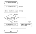
図6は、MFP110がサーバ120に対して行う登録要求処理のフローチャートである。この処理は、MFP110のRAM203、HDD205、ROM206のいずれかに記憶されたデータ同期アプリケーション400及びデータ管理アプリケーション410をCPU202が実行することで実現される。図6の処理は、例えば、サーバ120への最初の登録要求時(初期接続時)に実行される。
FIG. 6 is a flowchart of a registration request process performed by the
まず、ステップS601では、データ同期アプリケーション400の受付部401が、操作部220からの同期処理の開始要求を受信し、同期処理の開始要求を受信したことを制御部402へ通知する。ステップS602では、制御部402は、同期処理の開始要求を受信すると、接続先サーバが登録されているか、すなわち、同期処理を行うためのサーバ120のIPアドレスやホスト名が接続先として登録されているか否かを判別する。接続先サーバが登録されている場合には処理はステップS605へ進み、接続先サーバが登録されていない場合には処理はステップS603へ進む。
First, in step S601, the
制御部402は、ステップS603で、接続先のサーバ120を探索し、ステップS604で、サーバ探索により接続先のサーバ120が見つかったか否かを判別する。その判別の結果、制御部402は、接続先のサーバ120が複数見つかった場合、または接続先のサーバが見つからなかった場合には、図6の処理を終了させる。一方、1つの接続先のサーバ120が探索により見つかった場合には、制御部402は、処理をステップS605へ進める。ステップS605では、制御部402は、MFP110のデバイスの情報を表すデバイス情報データを生成し、それをジョブ管理部403にジョブとして登録する(ジョブを生成する)。ステップS605で生成されるデバイス情報データには、MFP110の現在時刻を表す情報(通知日時情報としてのMFP第1時刻T1)と、サーバが登録要求元の機器を特定する(デバイスを識別する)ための識別子情報とが含まれる。識別子情報は、クライアントを個々に特定できる情報であればよく、例えばデバイス毎に割り当てられるデバイスのシリアル番号であってもよい。
In step S603, the
次にステップS606では、制御部402は、ステップS605で生成されジョブ管理部403に登録されたジョブを読み出し、通信処理部404に対してサーバ120への送信処理を依頼する。次にステップS607では、制御部402は、MFP110上に存在するデータを元にサーバ120へ登録する登録データを生成する。ステップS608では、制御部402は、生成した登録データを通信処理部404へ渡し、サーバ120へ送信させる。これにより、同期要求のジョブがサーバ120へ送信され、ジョブの送信により通知日時情報がサーバ120へ通知される。
In step S606, the
図6の処理は、所定の処理の実行時、具体的にはサーバ120への最初の登録要求時に実行され、サーバ120の時刻とMFP110の時刻とを整合させるために必要な時刻補正の処理であった。しかし時刻を補正するタイミングは、最初の登録要求時だけに限定されるものではない。一般的なコンピュータに搭載されている時計は1カ月で15〜20秒程度ずれるものである。最初の登録要求時から1度も時刻が変更されていない場合には、MFP110aとMFP110bとサーバ120との時刻が互いにずれてしまい、同期上、問題となり得る。そのため、MFP110の起動時やスリープからの復帰時、サーバ120とMFP110との同期処理の一時停止からの再開時等、任意のタイミングで時刻補正を実施してもよい。これらにより、時計の経時的なずれを随時補正することができる。
The process of FIG. 6 is executed when a predetermined process is executed, specifically, when the first registration request is made to the
図7は、サーバ120で実行される登録処理のフローチャートである。この処理は、MFP110からの登録要求を受信した際にサーバ120で動作するサーバアプリケーション500による処理に対応する。なお、図7の各ステップは、サーバ120のCPU301がサーバアプリケーション500を実行することで実現される。以下の説明では、CPU301が実行するサーバアプリケーション500の各モジュールを、処理主体として説明する。
FIG. 7 is a flowchart of the registration process executed by the
なお、図7の処理では、サーバ120は、MFP110ごとに、登録要求時の同期要求のジョブに含まれる通知日時情報(ここではMFP第1時刻T1)を元に、「日時補正値」を記憶しておく。そしてサーバ120は、以降の同期要求に含まれる通知日時情報をサーバ120内での時刻に補正することで、複数のMFP110からの同期要求の順序の整合を保証する。
7, the
まず、ステップS701で、送受信部501が登録要求を受信すると、制御部502は、登録要求受信時におけるサーバ120の時計の日時をRAM302上に保持しておく。ステップS702では、受信した登録要求を解析部503が解析して識別子情報を特定し、制御部502は、特定された識別子情報から、登録要求元であるMFP110を特定する。そして制御部502はデータ処理部504に登録処理を要求する。ここで、識別子情報とは、前述のとおり、例えばMFP110のシリアル番号などである。
First, in step S <b> 701, when the transmission / reception unit 501 receives a registration request, the control unit 502 holds the date and time of the clock of the
ステップS703で、データ処理部504は、データ管理部510に対して要求元のMFP110がデータ管理部510に未登録であるか否かを判別する。その判別の結果、要求元のMFP110が既に登録されている場合は、今回の登録要求はエラーとなり、図7の処理が終了する。一方、要求元のMFP110が未登録である場合は、ステップS704で、データ処理部504は、MFP110をデータ管理部510に登録する。MFP110の識別子情報はHDD309に保存される。
In step S <b> 703, the data processing unit 504 determines whether the requesting
ステップS705では、データ処理部504は、MFP110からの登録要求に含まれていた通知日時情報(MFP第1時刻T1)を特定する。ステップS706では、ステップS701で保持したサーバ120における要求受信時の日時と、ステップS705で特定したMFP第1時刻T1とに基づいて「日時補正値」を算出する。サーバ120が有する時計が示す時刻を「サーバ時刻」と称する。「サーバ時刻」は、サーバ120内で動作するデータ管理サーバアプリケーション500が基準とする時刻とされる。日時補正値は、「日時補正値」=「通知日時情報」−「サーバ時刻」により算出される。ここでは、登録要求受け付け時の通知日時情報はMFP第1時刻T1であるので、日時補正値は、「日時補正値」=「MFP第1時刻T1」−「サーバ時刻」により算出される。従って、MFP110の時計がサーバ120の時計より進んでいる場合は、日時補正値は+の値となる。ステップS707では、データ処理部504は、ステップS706で算出した日時補正値(00:10)を、ステップS704で登録したMFP110の情報に関連付けて管理データとして保存するようにデータ管理部510に要求する。データ管理部510は、日時補正値を管理データに登録し、図7の処理が終了する。
In step S705, the data processing unit 504 specifies the notification date / time information (MFP first time T1) included in the registration request from the
表1に、サーバ120が管理する、日時補正値を含む管理データを示す。この例は、MFP110a及びMFP110bの登録処理完了後にデータ管理部510で管理されている管理データの一例である。MFP110aについては、日時補正値は「0:10」になっていて、サーバ120よりも10分間進んでいることを示している。MFP110bについては、日時補正値は「−00:10」となっていて、サーバ120よりも10分遅れていることを示している。

次に図8、図9を用いて、登録処理後にMFP110において設定値が変更された場合のMFP110とサーバ120との動作について説明する。
Next, operations of the
図8は、MFP110で実行される設定値更新処理のフローチャートである。図8の各ステップは、MFP110内のCPU202がROM206またはHDD205に記憶されたデータ同期アプリケーション400を実行することで実現される。
FIG. 8 is a flowchart of setting value update processing executed by the
まず、ステップS801において、受付部401は、操作部220等を用いて変更された設定値の変更内容とデータの変更日時とをデータ管理アプリケーション410から受信し、制御部402に通知する。ステップS802では、制御部402は、通知された内容をジョブ管理部403にジョブとして登録する。次に、ステップS803では、制御部402は、ジョブ管理部403に登録されているジョブを読み込み、読み込んだジョブのサーバ120への送信を通信処理部404に依頼する。これにより、ジョブがサーバ120へ送信される。その際、制御部402は、ジョブが複数登録されている場合は、先頭のジョブ(生成時刻が最も古いもの)から順に送信依頼する。なお、各ジョブ内には、ジョブ生成時の時刻、及び、ジョブ送信時の時刻が記載されている。ジョブ生成時刻を元に、送信の順番が定まる。
First, in step S <b> 801, the
ステップS804では、制御部402は、ジョブの送信が成功したか否かを判別する。その判別の結果、制御部402は、ジョブの送信が成功しなかった場合は、予め定められたリトライ間隔(規定時間)だけ待った後に(ステップS806)、再度、処理をステップS803へ進めてジョブの送信処理を実施する。一方、制御部402は、ジョブの送信が成功した場合は、ステップS805で、送信したジョブに関する削除処理をジョブ管理部403に依頼する。これにより、送信済みのジョブが削除される。なお、未送信のジョブが残っている場合は、処理はステップS803に戻る。未送信のジョブがなくなると図8の処理は終了する。
In step S804, the
図9は、サーバ120で実行される要求受信処理のフローチャートである。この処理は、MFP110から、データ更新要求、データ取得要求、または日時補正要求の同期ジョブをサーバ120が受信した場合に開始される。この処理は、CPU301が、サーバアプリケーション500を実行することで実現される。以下の説明では、CPU301が実行するサーバアプリケーション500の各モジュールを、処理主体として説明する。
FIG. 9 is a flowchart of request reception processing executed by the
まずステップS901で、送受信部501がMFP110からジョブを受信するとそれを制御部502に通知し、制御部502は、受信した内容を解析部503に渡して解析させ、その解析で特定された識別子情報から、要求元のMFP110を特定する。なお、ここで要求元が特定できない場合は、図示しないが、図8の処理はエラー終了となる。
First, in step S901, when the transmission / reception unit 501 receives a job from the
ステップS902では、制御部502は、解析部503から要求内容を取得し、ジョブによる要求がデータ更新要求であるか否かを判別する。その判別の結果、要求がデータ更新要求である場合は、制御部502は、ステップS903で、データ更新要求対応処理(図10で後述)を実行して図8の処理を終了させる。一方、要求がデータ更新要求でない場合は、ステップS904で、制御部502は、ジョブによる要求がデータ取得要求であるか否かを判別する。その判別の結果、要求がデータ取得要求である場合は、制御部502は、ステップS905で、データ取得要求対応処理(図12で後述)を実行して図8の処理を終了させる。一方、要求がデータ取得要求でない場合は、ステップS906で、制御部502は、ジョブによる要求が日時補正要求であるか否かを判別する。その判別の結果、要求が日時補正要求である場合は、制御部502は、ステップS907で、日時補正値更新処理(図15で後述)を実行して図8の処理を終了させる。一方、制御部502は、要求が日時補正要求でない場合は、図8の処理を終了させる。 In step S902, the control unit 502 acquires the request content from the analysis unit 503, and determines whether or not the request from the job is a data update request. As a result of the determination, if the request is a data update request, the control unit 502 executes a data update request handling process (described later in FIG. 10) and ends the process of FIG. 8 in step S903. On the other hand, if the request is not a data update request, in step S904, the control unit 502 determines whether the request by the job is a data acquisition request. As a result of the determination, if the request is a data acquisition request, the control unit 502 executes a data acquisition request handling process (described later in FIG. 12) and ends the process of FIG. 8 in step S905. On the other hand, if the request is not a data acquisition request, in step S906, the control unit 502 determines whether the request by the job is a date correction request. As a result of the determination, if the request is a date / time correction request, the control unit 502 executes date / time correction value update processing (described later in FIG. 15) in step S907 and ends the processing in FIG. On the other hand, when the request is not a date / time correction request, the control unit 502 ends the process of FIG.
図10は、図9のステップS903で実行されるデータ更新要求対応処理のフローチャートである。図10では、サーバ120が、データ更新要求として、MFP110からアドレスデータ更新要求のジョブを受信した場合における、サーバアプリケーション500による処理を例示する。日時につき一例を加えつつ処理を説明する。
FIG. 10 is a flowchart of the data update request response process executed in step S903 of FIG. FIG. 10 illustrates processing by the server application 500 when the
まずステップS1001では、制御部502は、更新要求元のMFP110に関する日時補正値(MFP110aについては「00:10」;表1参照)をデータ管理部510内の管理データから取得する。ステップS1002では、制御部502は、解析部503から受信した内容の日時情報(通知日時情報)として例えば「2015/01/01・11:10」を取得する。ステップS1003では、制御部502は、ステップS1002で取得した通知日時情報を、ステップS1001で取得した日時補正値で補正することで、更新データの日時情報である補正後の時刻「2015/01/01:11:00」を求める。これにより、データ更新要求時のMFP110での時刻をサーバ120が認識(特定)することができる。
First, in step S <b> 1001, the control unit 502 acquires a date correction value (“00:10” for the
ステップS1004では、制御部502は、解析部503から更新対象のデータ内容を取得して、データ処理部504に、データ内容とステップS1003で求めた補正後の時刻情報を渡す。データ処理部504は、更新対象のデータの最終更新日時をデータ管理部510から取得する。最終更新日時とは、各MFP110においてデータが更新された時刻をサーバ120の時刻に補正した時間情報であり、各MFP110からの更新要求の前後関係を判断するために利用される。ステップS1005では、データ処理部504は、ステップS1004で取得した更新対象のアドレスデータの最終更新日時と、ステップS1003で求めた補正後の日時とを比較し、最終更新日時よりも補正後の日時の方が新しいか否かを判別する。その判別の結果、最終更新日時よりも補正後の日時の方が新しい場合は、処理はステップS1006へ進む。
In step S1004, the control unit 502 acquires the data content to be updated from the analysis unit 503, and passes the data content and the corrected time information obtained in step S1003 to the data processing unit 504. The data processing unit 504 acquires the last update date / time of the data to be updated from the data management unit 510. The last update date and time is time information obtained by correcting the time at which data is updated in each
ステップS1006では、データ処理部504が、更新対象のアドレスデータを要求された値で更新するようデータ管理部510に対して要求する。すると、データ管理部510は、保持している管理データに含まれるアドレスデータを更新する。また、データ処理部504は、更新されたアドレスデータの最終更新日時を補正後の日時に更新すると共に、データ更新日時を処理実行時のサーバ時刻(例えば「2015/01/01:11:01」)に更新する。データ更新日時とは、サーバ120のデータ管理部510にデータを反映させた時刻であり、各MFP110がサーバ上の更新内容を取得する際に利用される時間情報である。
In step S1006, the data processing unit 504 requests the data management unit 510 to update the address data to be updated with the requested value. Then, the data management unit 510 updates the address data included in the held management data. The data processing unit 504 updates the last update date and time of the updated address data to the corrected date and time, and sets the data update date and time to the server time at the time of processing execution (for example, “2015/01/01: 11: 01”). ). The data update date and time is the time when the data is reflected in the data management unit 510 of the
一方、ステップS1005の判別の結果、最終更新日時よりも補正後の日時の方が新しくない場合は、データ処理部504は、ステップS1007で、受信したジョブに対応する要求内容を破棄して、処理をステップS1008へ進める。ステップS1008では、送受信部501が更新完了の応答を要求元へ返信し、図10の処理が終了する。なお、当該更新完了の応答を要求元のMFP110が所定時間内に受信していないと判断した場合、MFP110がネットワーク100に接続されていないとサーバ120は判断することができる。
On the other hand, if it is determined in step S1005 that the corrected date and time is not newer than the last updated date and time, the data processing unit 504 discards the request content corresponding to the received job in step S1007 and performs processing. Advances to step S1008. In step S1008, the transmission / reception unit 501 returns an update completion response to the request source, and the processing in FIG. 10 ends. When it is determined that the requesting
次に図11、12を用いてMFP110が更新データの取得をサーバ120へ要求する際のMFP110内のデータ同期アプリケーション400とサーバ120内のサーバアプリケーション500の動作について説明する。
Next, operations of the
図11は、MFP110により実行されるデータ取得処理のフローチャートである。図11の各ステップは、MFP110内のCPU202がデータ同期アプリケーション400を実行することで実現される。図11の処理は、例えば、図6の登録要求処理の後に、MFP110(例えば、MFP110b)において変更された設定値を他のMFP110(例えば、MFP110a)が取得するための要求を行う処理である。サーバ120上に反映された設定値のMFP110への反映処理は、MFP110からの変更内容の取得要求により実現される。この変更内容の取得要求は、一定間隔毎に実行されるか、あるいは、ユーザのログインをトリガにしてユーザのログイン処理と併せて実行される。
FIG. 11 is a flowchart of data acquisition processing executed by the
まず、ステップS1101では、受付部401は、ユーザが操作部220を通してMFP110にログインしたこと、または、前回の変更内容の取得要求から一定時間経過したこと、を元に発生するデータ取得要求を受信する。このデータ取得要求には、取得対象となるデータを示す情報と前回にサーバ120からデータを取得した時の最終更新日時の情報を含むものであり、制御部402へ通知される。ステップS1102では、制御部402は、通信処理部404へデータ取得要求を通知し、通信処理部404はサーバ120へデータ取得要求を送信する。制御部402は、ステップS1103で、データ取得要求の送信が成功したか否かを判別し、データ取得要求の送信が成功した場合は、サーバ120からの返信結果に含まれる最終更新日時を取得し、それを更新する。一方、データ取得要求の送信が失敗した場合は、制御部402は、図11の処理を終了させる。
First, in step S <b> 1101, the
図12は、図8のステップS905で実行されるデータ取得要求対応処理のフローチャートである。ステップS1201では、制御部502は、受信した内容を解析部503に渡して、データ取得の対象を特定する。ステップS1202では、制御部502は、解析部503から、取得要求に含まれていた最終データ取得日時を特定し、データ処理部504に、データが例えばアドレスデータであることを示す情報、及び最終データ取得日時の情報を渡す。ステップS1203では、データ処理部504は、データ管理部510に、アドレスデータのうち最終データ取得日時以降に更新されたアドレスデータが存在するか否かを判別する。データ管理部510は、管理しているデータ更新日時が最終データ取得日時以降であるアドレスデータを特定し、それをデータ処理部504へ返却することで通知する。 FIG. 12 is a flowchart of the data acquisition request handling process executed in step S905 of FIG. In step S <b> 1201, the control unit 502 passes the received content to the analysis unit 503 and identifies the data acquisition target. In step S1202, the control unit 502 specifies the last data acquisition date and time included in the acquisition request from the analysis unit 503, and sends to the data processing unit 504 information indicating that the data is address data, for example, and the final data. Pass the acquisition date information. In step S1203, the data processing unit 504 determines whether or not the data management unit 510 has address data updated after the last data acquisition date and time among the address data. The data management unit 510 identifies address data whose managed data update date and time is after the last data acquisition date and time, and notifies the data processing unit 504 by returning it.
その判別の結果、最終データ取得日時以降に更新されたアドレスデータが存在する場合は、データ処理部504は、ステップS1204で、返却されたアドレスデータと、ステップS1203の処理実行時の日時情報とを要求元に返信する。一方、最終データ取得日時以降に更新されたアドレスデータが存在しない場合は、データ処理部504は、ステップS1205で、ステップS1203の処理実行時の日時情報のみを要求元に返信する。ステップS1204、S1205の処理後、図12の処理は終了する。 As a result of the determination, if there is updated address data after the last data acquisition date and time, the data processing unit 504 obtains the returned address data and the date and time information at the time of execution of the processing in step S1203 in step S1204. Reply to the requester. On the other hand, if there is no address data updated after the last data acquisition date and time, the data processing unit 504 returns only the date and time information at the time of execution of the processing in step S1203 to the request source in step S1205. After the processes of steps S1204 and S1205, the process of FIG.
ここで、図12の処理を、表2を用いて具体例を挙げて説明する。
例えば、MFP110aからのデータ取得要求がなされ、最終データ取得日時として「2015/01/01・11:00」がデータ取得要求に含まれているとする。データ管理部510は、この「2015/01/01・11:00」よりも新しいデータ更新日時の情報を検索する。表2(c)から、AddressAのメールアドレスデータのデータ更新日時が「2015/01/01・11:01」であるので、データ取得要求に対して、このメールアドレスデータが返信される。
For example, it is assumed that a data acquisition request is made from the
また、ステップS1203の処理実行日時が「2015/01/01・12:10」である場合、処理完了後のMFP110aのデータ管理アプリケーション410が保持するメールアドレスデータは、表2(a)に示すものとなる。また、MFP110bも同様のデータ取得処理を実行し、その時のステップS1203の処理実行日時が「2015/01/01・12:11」であるとする。この場合、MFP110bのデータ管理アプリケーション410が保持するメールアドレスデータは表2(b)に示すものとなる。
Further, when the processing execution date and time of step S1203 is “2015/01/01 · 12: 10”, the mail address data held by the
図13(a)は、MFP110で実行される時刻変更処理のフローチャートである。この処理は、MFP110が有する時計の時間が変更(修正)された場合に実行される。図13(a)の各ステップは、MFP110のRAM203、HDD205、ROM206のいずれかに記憶されたデータ同期アプリケーション400及びデータ管理アプリケーション410をCPU202が実行することで実現される。
FIG. 13A is a flowchart of time change processing executed by the
まずステップS1301では、日時変更検知部405は、MFP110の時計の時刻が変更されたことを検知し、そのことを制御部402に通知する。ステップS1302では、制御部402は、時刻変更量算出処理(図13(b)で後述)を実行し、変更量算出部406に時計の時間の変更前後の変化量(「時刻変更量ΔT」と記す)を算出させる。次にステップS1303では、ステップS1302で算出した時刻変更量ΔTを元に時刻変更ジョブを生成し、ジョブ管理部403にこのジョブを登録する。時刻変更量ΔTはジョブにジョブ情報として保持される。ステップS1304では、制御部402は、時刻変更ジョブ送信処理(図14(a)で後述)を実行する。その詳細は後述するが、制御部402は、ジョブ管理部403からジョブを取得し、通知時刻生成部407によりサーバ120へ通知すべき通知日時情報を生成し、通信処理部404にジョブの送信処理を依頼する。
First, in step S1301, the date / time
ステップS1305では、制御部402は、ジョブの送信に成功したか否かを判別し、ジョブの送信に失敗した場合には再度、ステップS1304からやり直す。一方、ジョブの送信に成功した場合は、ステップS1306で、制御部402は、差分時間更新処理(図14(b)で後述)を実行する。その後、ステップS1307では、制御部402は、送信したジョブに関する削除処理をジョブ管理部403に依頼する。これにより、送信済みのジョブが削除される。
In step S1305, the
図13(b)は、図13(a)のステップS1302で実行される時刻変更量算出処理のフローチャートである。まず、ステップS1310では、制御部402は、RAM203に記憶されている変更前の計時情報を取得する。変更前の計時情報の一例を表3に示す。
RAM203には、変更前の計時情報として、ある時点における時刻カウンタと時刻情報のスナップショットの値が保持されている。時刻カウンタは、MFP110の起動時に0に初期化され、MFP110の電源遮断時までカウントアップされる。時刻カウンタは、計時機能を有すればよく、MFP110が有する時計とは独立した計時装置でもよい。時刻情報は、MFP110のデバイスが持つ時計が示す時刻である。表3に示される変更前の計時情報の値は、デバイスの起動時の値、もしくは後述するステップS1313で更新された値である。ステップS1311では、制御部402は、変更後の計時情報を取得し、RAM203に一時的に保持する。変更後の計時情報とは、現時点における時刻カウンタの値と現時点におけるデバイスが持つ時計が示す時刻である。時刻変更がされた後に取得された時刻カウンタの値及び時刻情報のスナップショットである変更後の計時情報の一例を表4に示す。
ステップS1312では、制御部402は、ステップS1310で取得した変更前の計時情報とステップS1311で取得した変更後の計時情報とから、変更量算出部406に時刻変更量ΔTを算出させる。今回の時刻変更量ΔTは、「変更後と変更前との時刻情報のスナップショットの差分」−「変更後と変更前との時刻カウンタの値の差分」により算出される。例えば、表3及び表4を例にとると以下のように計算される。
In step S1312, the
時刻カウンタの差分値は4600−1000=3600秒となり、時刻カウンタが1時間進んだことがわかる。一方、時刻情報のスナップショットは9:30−8:00=1:30となり、1時間30分進んだことがわかる。そのため、1時間30分−1時間=30分となり、表5に示すように、時刻変更量ΔTとして30分が算出される。つまり時計が30分、進み方向へ修正されたことがわかる。
ステップS1313では、ステップS1311で取得した変更後の計時情報(表4)を用いて、表3に示す変更前の計時情報(表3)を更新する。これは、ステップS1311で取得した変更後の計時情報を、次回以降の時刻変更時には変更前の計時情報として利用するためである。ステップS1314では、制御部402は、差分時間管理部408に、差分時間dTの更新を依頼する。これにより、差分時間管理部408は、現在管理されている差分時間dTに、ステップS1312で算出した時刻変更量ΔTを加算することで差分時間dTを更新する。
In step S1313, the time information before change shown in Table 3 (Table 3) is updated using the time information after change (Table 4) acquired in Step S1311. This is because the changed time information acquired in step S1311 is used as time information before the change when the time is changed after the next time. In step S1314, the
ここで、通知日時情報は、ステップS606、後述するステップS1324の処理によってサーバ120へ通知される。差分時間dTは、前述のように通知日時情報に基づき定まる値であるが、初期値は0であり、HDD205等の不揮発な領域において保持され、前述のステップS1314、及び、後述するステップS1331で算出し直されて更新される。すなわち、MFP110とサーバ120の間で正しく同期できている場合には差分時間dTの値は0になる。しかしネットワーク100に問題がある場合や、サーバ120が装置のメンテナンス等により停止されている間にMFP110の時計が変更された場合には、この値には時刻変更の度にステップS1312で算出された時刻変更量ΔTが加算される。
Here, the notification date and time information is notified to the
なお、図13(b)の処理では、時刻カウンタと時刻情報のスナップショットの2つを用いて時刻変更量ΔTを算出したが、この算出方法に限定するものではない。例えばユーザが操作部220から時計を変更する際に、デバイスの時計とユーザが入力した時刻との差分値を算出し、それらの値をRAM203やHDD205に保持しておき、時刻変更量ΔTとして読み込むようにしても良い。
In the process of FIG. 13B, the time change amount ΔT is calculated using the time counter and the time information snapshot, but the present invention is not limited to this calculation method. For example, when the user changes the clock from the
図14(a)は、図13(a)のステップS1304で実行される時刻変更ジョブ送信処理のフローチャートである。まず、ステップS1320で、制御部402は、現在のMFP110の時計が示すMFP第1時刻T1を取得する。ステップS1321では、制御部402は、ステップS1314で算出した差分時間dTを差分時間管理部408から取得する。ステップS1322では、制御部402は、ステップS1302で算出された時刻変更量ΔTを取得する。ステップS1323では、制御部402は、差分時間dTと時刻変更量ΔTとに基づいて、数式1により算出時刻cTを算出する。この算出時刻cTが、次に通知すべき通知日時情報となる。
[数1]
算出時刻cT=ステップS1320で取得したMFP第1時刻T1−差分時間dT+時刻変更量ΔT
FIG. 14A is a flowchart of the time change job transmission process executed in step S1304 of FIG. First, in step S1320,
[Equation 1]
Calculation time cT = MFP first time T1−difference time dT acquired in step S1320 + time change amount ΔT
次に、ステップS1324では、制御部402は、算出時刻cTを通知日時情報として時刻変更ジョブに含め、通信処理部404にそのジョブの送信処理を依頼する。通信処理部404が時刻変更ジョブを送信することで、通知日時情報がサーバ120に通知される。その後、図14(a)の処理は終了する。なお、ステップS1324で、ジョブの送信ができなかった場合は、そのジョブはジョブ管理部403が持つキューに未処理のジョブとして保持され、一定時間経過後に再度送信処理がなされる。送信順序はジョブの生成順となる。
Next, in step S1324, the
図14(b)は、図13(a)のステップS1306で実行される差分時間更新処理のフローチャートである。まず、ステップS1330では、制御部402は、ステップS1312で算出された時刻変更量ΔTをジョブ管理部403から取得するか、もしくはRAM203に保持されているジョブ情報を読み出して時刻変更量ΔTを取得する。ステップS1331では、制御部402は、差分時間管理部408に、差分時間dTの更新を依頼する。これにより、差分時間管理部408は、現在管理されている差分時間dTからステップS1330で取得した時刻変更量ΔTを減算することで差分時間dTを更新する。ここでいう時刻変更量ΔTは、今回送信した時刻変更ジョブに含まれていた算出時刻cTの算出に用いられた時刻変更量ΔTである。時計の変更が1回しかされていない場合には、この時点で差分時間dTは0となる。その後、図14(b)の処理は終了する。
FIG. 14B is a flowchart of the differential time update process executed in step S1306 of FIG. First, in step S1330, the
図15は、図9のステップS907で実行される日時補正値更新処理のフローチャートである。MFP110からの日時補正要求をサーバ120のサーバアプリケーション500が受信すると、まず、ステップS1501で、制御部502は、日時補正要求の受信時における日時情報であるサーバ時刻(例えば「2015/01/01・8:30」)を特定する。ステップS1502では、制御部502は、解析部503の解析結果から、要求に含まれる通知日時情報であるジョブ送信時のMFP第1時刻T1(例えば「2015/01/01・9:30」)を特定する。
FIG. 15 is a flowchart of the date / time correction value update processing executed in step S907 of FIG. When the server application 500 of the
ステップS1503では、制御部502は、ステップS1501、S1502でそれぞれ特定した日時情報から日時補正値を求める。具体的には、「2015/01/01・9:30」−「2015/01/01・8:30」から「01:00」が日時補正値として算出される。ステップS1504で、制御部502は、データ処理部504に日時補正を依頼する。すると、データ処理部504は、日時補正値をステップS1503で算出した値「01:00」に更新するようデータ管理部510に依頼し、データ管理部510が日時補正値を更新する。その後、図15の処理は終了する。MFP110a、MFP110bに関して、更新処理実行後のデータ管理部510が管理する情報の例を表6に示す。
次に、表7及び表8を用いて、電源遮断等のサーバとの通信ができない状況等において、設定値の変更や複数回の時刻変更がなされた場合の処理動作、及び、通信が再開した後の動作処理の例を説明する。
表7は、MFP110で発生したデータの同期処理に関連するイベントに関する内容と、その時点のサーバ120及びMFP110の時刻を表したものである。サーバ時刻とは、前述のように、サーバアプリケーション500が基準としている時刻であり、MFP時刻とはMFP110内の時計が示す時刻である。但し時計の変更があった時には変更後の時刻を示している。まず、表7の1行目に示す初期状態では、MFP時刻はサーバ時刻よりも1時間進んでいることがわかる。差分時間は、サーバ120が記憶している日時補正値と、サーバ120の時計が計時する時刻とMFP110の時計が計時する時刻の実際の差を示す値との差分を示す。
Table 7 shows the contents related to the event related to the data synchronization processing generated in the
まずサーバ時刻9:00には、サーバ120の動作停止か、サーバ120までの経路のネットワーク100の問題により、MFP110がサーバ120と通信ができない状況が発生している。従って、これ以降、サーバ復帰までは同期要求ジョブ(設定値の変更や時刻変更を含む)をサーバ120に送信することができないため、ジョブはジョブ管理部403が持つジョブのキューに未処理のジョブとして保持される。
First, at the server time 9:00, there is a situation in which the
次にサーバ時刻9:10には、MFP時刻が10:10の時に、ID0001のアドレス帳のデータにおいて、名称がAddressA、アドレスがa@aに更新される。次にサーバ時刻9:20には、MFP110の時計が修正(1回目の時刻変更)され、MFP時刻が10:20から10:40へと、20分進められる(時刻変更量ΔT=00:20)。この時、差分時間dTには20分が加算され、差分時間dTは0:20に更新される。サーバ時刻9:30には、MFP110が再起動される。MFP110が再起動されると、RAM203で保持されている時刻カウンタと時刻情報のスナップショットの値(表3参照)は一旦クリアされ、再起動時に、改めてそれらの値が取得されて変更前の計時情報としてRAM203に記録される。
Next, at the server time 9:10, when the MFP time is 10:10, the name is updated to Address A and the address is a @ a in the address book data of ID0001. Next, at the server time 9:20, the clock of the
サーバ時刻9:40には、MFP時刻が11:00の時に、ID0002のアドレス帳のデータにおいて、名称がAddressB、アドレスがb@bに更新される。サーバ時刻9:50には、MFP110の時計が修正(2回目の時刻変更)され、MFP時刻が11:10から11:40へと、30分進められる(時刻変更量ΔT=00:30)。この時、差分時間dTには30分が加算され、差分時間dTは0:50に更新される。サーバ時刻10:00にはサーバ120が復帰し、MFP110とサーバ120との通信が再開する。
At server time 9:40, when the MFP time is 11:00, in the address book data of ID0002, the name is updated to Address B and the address is updated to b @ b. At the server time 9:50, the clock of the
次に、表8で、MFP110とサーバ120との通信が再開した後に、MFP110のデータ同期アプリケーション400で実行される処理について説明する。サーバ120との通信が再開されると、制御部402は、ジョブ管理部403のキューに保持されたジョブを、ジョブの投入順(生成順)に送信する。なお、実際には通信再開後には直ちにジョブが順次実行されるため、短時間でジョブが処理されるが、ここでは理解容易化のため、10分毎に1つのジョブが送信処理されるとして説明する。
Next, in Table 8, processing executed by the
表8において、サーバ時刻の意味は表7におけるものと同じであり、サーバ120が管理する基準となる時刻である。サーバが認識(特定)するMFP時刻とは、サーバ120が認識するMFP110におけるMFP時刻であり、「サーバ時刻」+「日時補正値」により算出される。例えば、サーバ120は、サーバ時刻9:00以前の段階で、MFP時刻はサーバ時刻に対して1時間進んでいることがわかっており、新たな通知日時情報を受けるまではその認識のままである。従って、サーバ時刻10:10に対して1時間加算した11:10が、サーバ120が特定するMFP時刻となる。MFP時刻(ジョブ送信時)とは、実際にジョブを送信する時点でのMFP110の時計が示す時刻である。表7を用いて説明した例では、サーバ時刻10:00の時点では、MFP110の時計が計時する時刻はサーバ時刻よりも1時間50分進んでいる。ジョブ内の時刻(生成時)は、ジョブが生成・投入された時のMFP時刻である。
In Table 8, the meaning of the server time is the same as that in Table 7 and is a reference time managed by the
表8のサーバ時刻10:10には、表7のMFP時刻10:10(サーバ時刻9:10)に投入(生成)された、値の変更に関するジョブが実行される。サーバ120は、受信したジョブ内を解析し、ジョブ内に記載されたジョブ生成時刻である10:10に対して、日時補正値である「1:00」を減算して9:10を導き出す。これにより、今回のジョブが、サーバ時刻でいう9:10に生成されたジョブであるとサーバ120は認識する。すなわち、ジョブが、サーバ時刻を基準としていつの時点で生成されたのかが、ジョブ生成時刻−日時補正値により導出される。今回処理したジョブは表7のMFP時刻10:10に投入されたジョブであるが、その時点のサーバ時刻は9:10であったため、正しい時刻へと補正されジョブ処理が実行されることになる。
At server time 10:10 in Table 8, a job relating to a value change, which is input (generated) at MFP time 10:10 (server time 9:10) in Table 7, is executed. The
次にサーバ時刻10:20には、1回目の時刻変更のジョブが実行される。この時点で、ジョブ送信時刻はMFP時刻12:10(MFP第1時刻T1)、差分時間dTは「00:50」、ジョブ内に含まれる時刻変更量ΔTは「00:20」である。従って制御部402は、数式1に従って、12:10−0:50+0:20=11:40により算出時刻cTを算出し、算出時刻cT(11:40)を通知日時情報としてジョブに含めてサーバ120へ通知する。一方、サーバ120は、受信したジョブ内を解析し、ジョブ内に記載された通知日時情報である11:40と、現在のサーバ時刻である10:20とから、MFP時刻がサーバ時刻に対して1:20だけ進んでいると認識できる。そしてサーバ120は、この1:20の値を、MFP110に関する日時補正値としてデータ管理部510に保存する。日時補正値が1:00から1:20に変更されるので、サーバ時刻10:20においてサーバが特定するMFP時刻は11:20から11:40に変更される。サーバ120の処理が正常に終了すると、MFP110は、送信したジョブに含まれていた算出時刻の算出に用いられた時刻変更量ΔT(0:20)を差分情報dT(0:50)から減算して差分時間dTを更新する。差分時間dTは0:30となる。
Next, at the server time 10:20, the first time change job is executed. At this time, the job transmission time is MFP time 12:10 (MFP first time T1), the difference time dT is “00:50”, and the time change amount ΔT included in the job is “00:20”. Therefore, the
表8のサーバ時刻10:30には、表7のMFP時刻11:00に投入(生成)された、値の変更に関するジョブが実行される。サーバ120は、受信したジョブ内を解析し、ジョブ内に記載されたジョブ生成時刻である11:00に対して、日時補正値である1:20を減算して9:40を導き出す。これにより、今回のジョブが、サーバ時刻でいう9:40に生成されたジョブであるとサーバ120は認識する。今回処理したジョブは表7のMFP時刻11:00に投入されたジョブであるが、その時点のサーバ時刻は9:40であったため、正しい時刻へと補正されジョブ処理が実行されることになる。
At server time 10:30 in Table 8, a job relating to a value change, which is input (generated) at MFP time 11:00 in Table 7, is executed. The
次にサーバ時刻10:40には、2回目の時刻変更のジョブが実行される。この時点で、ジョブ送信時刻はMFP時刻12:30(MFP第1時刻T1)、差分時間dTは「00:30」、ジョブ内に含まれる時刻変更量ΔTは「00:30」である。従って制御部402は、数式1に従って、12:30−0:30+0:30=12:30により算出時刻cTを算出し、算出時刻cT(12:30)を通知日時情報としてジョブに含めてサーバ120へ通知する。一方、サーバ120は、受信したジョブ内を解析し、ジョブ内に記載された通知日時情報である12:30と、現在のサーバ時刻である10:40とから、MFP時刻がサーバ時刻に対して1:50だけ進んでいると認識できる。そしてサーバ120は、この1:50の値を、MFP110に関する日時補正値としてデータ管理部510に保存する。日時補正値が1:20から1:50に変更されるので、サーバ時刻10:40においてサーバが特定するMFP時刻は12:00から12:30に変更される。サーバ120の処理が正常に終了すると、MFP110は、送信したジョブに含まれていた算出時刻の算出に用いられた時刻変更量ΔT(0:30)を差分情報dT(0:30)から減算して差分時間dTを更新する。差分時間dTは0:00となる。
Next, a second time change job is executed at the server time 10:40. At this time, the job transmission time is MFP time 12:30 (MFP first time T1), the difference time dT is “00:30”, and the time change amount ΔT included in the job is “00:30”. Accordingly, the
以上に説明したように、MFP110は、時刻が変更された場合には時刻変更量ΔTをジョブ情報として保持しておき、その後、実際にジョブを送信する時点で、差分時間dTと時刻変更量ΔTとジョブ送信時刻とから、通知日時情報を算出する。サーバ120は、通知日時情報から、ジョブが投入されたMFP時刻を正しく認識できる。従って、ネットワーク100の問題、MFP110の電源遮断、サーバ120の停止等によって、MFP110とサーバ120とが通信不能な時間帯に複数回の時刻変更や設定値の変更が実施された場合であっても、正しい時刻で設定値の同期が行える。
As described above, the
本実施の形態によれば、MFP110の時計の時間が変更された場合に時刻変更量ΔTが算出され、差分時間dTと時刻変更量ΔTとに基づいて算出された算出時刻cTが通知日時情報としてサーバ120へ通知される。これにより、サーバ120と通信不能な時間帯にMFP110で時計の時間変更があっても、通信再開後にサーバとの時間的整合を確保することができる。
According to the present embodiment, the time change amount ΔT is calculated when the clock time of the
特に、MFP110は、時刻変更ジョブの生成時に、差分時間dTを、時刻変更量ΔTの加算により更新し、ジョブの送信後には、時刻変更量ΔTの減算により差分時間dTを更新する。これにより、通信不能時間帯に複数回の時計の時間変更があっても、通信再開後にサーバとの時間的整合を確保することができる。
In particular, the
(第2の実施の形態)
第1の実施の形態では、MFP110において時計が変更された場合に通知日時情報として算出時刻cTをサーバ120に通知することで、サーバ120とMFP110との時刻の差分を管理していた。しかし、時計が変更されたタイミングで、サーバ120へは時刻の変化量のみを通知する構成としても、同期処理を正しく実施できる。そこで本発明の第2の実施の形態では、時計の変更時には時刻の変化量を送信する構成を採用する。従って、図13(a)、(b)、図14(a)に代えて図16(a)、(b)、(c)を用い、図9、図15に代えて図17、図18を用いて第2の実施の形態を説明する。図14(b)は用いない。その他の構成は第1の実施の形態と同様である。ところで、第2の実施の形態では、差分時間管理部408を用いる必要がない。そのため、MFP110の構成(図4)から差分時間管理部408を廃止してもよい。
(Second Embodiment)
In the first embodiment, the time difference between the
図16(a)は、MFP110で実行される時刻変更処理のフローチャートである。この処理は、MFP110が有する時計の時間が変更(修正)された場合に実行される。図16(a)の各ステップは、MFP110のRAM203、HDD205、ROM206のいずれかに記憶されたデータ同期アプリケーション400及びデータ管理アプリケーション410をCPU202が実行することで実現される。なお、図16(a)〜(c)において、図13(a)、(b)、図14(a)と同一のステップ番号が付された処理は、第1の実施の形態と同一の処理が実行されることを示している。主に、第1の実施の形態と異なる処理ステップについて説明する。
FIG. 16A is a flowchart of time change processing executed by the
なお、図16(a)では、図13(a)に対し、ステップS1306が削除され、ステップS1302、S1304に代えて、ステップS1602、S1604が設けられている。ステップS1602では、制御部402は、時刻変更量算出処理(図16(b)で後述)を実行し、変更量算出部406に時計の時間の変更前後の変化量(時刻変更量ΔT)を算出させる。次にステップS1604では、制御部402は、時刻変更ジョブ送信処理(図16(c)で後述)を実行する。
In FIG. 16A, step S1306 is deleted from FIG. 13A, and steps S1602 and S1604 are provided instead of steps S1302 and S1304. In step S1602, the
図16(b)は、図16(a)のステップS1602で実行される時刻変更量算出処理のフローチャートである。なお、図16(b)では、図13(b)からステップS1314が削除され、その他は同様である。図16(c)は、図16(a)のステップS1604で実行される時刻変更ジョブ送信処理のフローチャートである。図16(c)では、図14(a)からステップS1320、S1321が削除され、ステップS1323、S1324に代えてステップS1623、S1624が設けられている。 FIG. 16B is a flowchart of the time change amount calculation process executed in step S1602 of FIG. In FIG. 16B, step S1314 is deleted from FIG. 13B, and the others are the same. FIG. 16C is a flowchart of the time change job transmission process executed in step S1604 of FIG. In FIG. 16C, steps S1320 and S1321 are deleted from FIG. 14A, and steps S1623 and S1624 are provided instead of steps S1323 and S1324.
ステップS1623では、制御部402は、ステップS1322で取得した時刻変更量ΔTをそのまま「通知日時情報」として通知時刻生成部407に設定する。ステップS1624では、制御部402は、時刻変更量ΔTを通知日時情報として時刻変更ジョブに含め、通信処理部404にそのジョブの送信処理を依頼する。通信処理部404が時刻変更ジョブを送信することで、時刻変更量ΔTがサーバ120に通知される。その後、図16(c)の処理は終了する。なお、ステップS1624で、ジョブの送信ができなかった場合は、そのジョブはジョブ管理部403が持つキューに未処理のジョブとして保持され、一定時間経過後に再度送信処理がなされる。送信順序はジョブの生成順となる。
In step S <b> 1623, the
図17は、サーバ120で実行される要求受信処理のフローチャートである。この処理は、MFP110から、データ更新要求、データ取得要求、または日時補正要求の同期ジョブをサーバ120が受信した場合に開始される。この処理は、CPU301が、サーバアプリケーション500を実行することで実現される。以下の説明では、CPU301が実行するサーバアプリケーション500の各モジュールを、処理主体として説明する。なお、図17では、図9に対して、ステップS908に代えてステップS1707が設けられている。その他のステップの処理は第1の実施の形態と同様である。
FIG. 17 is a flowchart of request reception processing executed by the
なお、図17、図18において、図9、図15と同一のステップ番号が付された処理は、第1の実施の形態と同一の処理が実行されることを示している。主に、第1の実施の形態と異なる処理ステップについて説明する。ステップS1707では、日時補正値更新処理(図18で後述)を実行して図17の処理を終了させる。 In FIG. 17 and FIG. 18, the processes with the same step numbers as those in FIG. 9 and FIG. 15 indicate that the same processes as those in the first embodiment are executed. Processing steps different from those of the first embodiment will be mainly described. In step S1707, date correction value update processing (described later in FIG. 18) is executed, and the processing in FIG. 17 is terminated.
図18は、図17のステップS1707で実行される日時補正値更新処理のフローチャートである。なお、図18では、図15に対して、ステップS1502、S1503に代えてステップS1802、S1803が設けられている。 FIG. 18 is a flowchart of the date / time correction value update process executed in step S1707 of FIG. In FIG. 18, steps S1802 and S1803 are provided in place of steps S1502 and S1503 with respect to FIG.
ステップS1802では、制御部502は、解析部503の解析結果から、要求に含まれる通知日時情報である時刻変更量ΔT(例えば「01:00」)を特定する。ここで、「01:00」は、符号が+であるので、MFP110の実際の時刻を特定するには、現在、サーバ120がデータ管理部510内で管理しているMFP110に関する日時補正値に対して1時間を加算する必要がある。
In step S1802, the control unit 502 specifies a time change amount ΔT (for example, “01:00”) that is notification date and time information included in the request from the analysis result of the analysis unit 503. Here, since the sign of “01:00” is +, in order to specify the actual time of the
ステップS1803では、データ処理部504は、データ管理部510から、現在の日時補正値を取得し、この日時補正値に、ステップS1802で特定した時刻変更量ΔTである「01:00」を加算して新たな日時補正値を算出する。ステップS1504では、制御部502は、データ処理部504に日時補正を依頼する。すると、データ処理部504は、現在の日時補正値を、ステップS1803で新たに算出した日時補正値に更新するようデータ管理部510に依頼し、データ管理部510が日時補正値を更新する。その後、図18の処理は終了する。MFP110a、MFP110bに関して、データ管理部510が管理する情報は、図18の処理が、MFP110aに関するものであるとした場合、更新処理実行前に表6に示すものであったものが、更新処理実行後には表9に示すものへと更新される。
以上のように、MFP110は、時計の時刻が変更された場合に、通知日時情報として時刻変更量ΔTをジョブ情報として記憶しておき、サーバ120に対して、時刻変更量ΔTを通知する。サーバ120は、データ管理部510により管理される日時補正値に時刻変更量ΔTを直接加算して更新することで、日時補正値とサーバ時刻とから、ジョブが投入されたMFP時刻を正しく認識できる。よって、サーバ120と通信不能な時間帯にMFP110で複数回の時計の時間変更があっても、通信再開後にサーバとの時間的整合を確保することに関し、第1の実施の形態と同様の効果を奏することができる。
As described above, when the clock time is changed, the
(その他の実施例)
本発明は、上述の実施形態の1以上の機能を実現するプログラムを、ネットワーク又は記憶媒体を介してシステム又は装置に供給し、そのシステム又は装置のコンピュータにおける1つ以上のプロセッサーがプログラムを読出し実行する処理でも実現可能である。また、1以上の機能を実現する回路(例えば、ASIC)によっても実現可能である。
(Other examples)
The present invention supplies a program that realizes one or more functions of the above-described embodiments to a system or apparatus via a network or a storage medium, and one or more processors in a computer of the system or apparatus read and execute the program This process can be realized. It can also be realized by a circuit (for example, ASIC) that realizes one or more functions.
以上、本発明をその好適な実施形態に基づいて詳述してきたが、本発明はこれら特定の実施形態に限られるものではなく、この発明の要旨を逸脱しない範囲の様々な形態も本発明に含まれる。上述の実施形態の一部を適宜組み合わせてもよい。 Although the present invention has been described in detail based on preferred embodiments thereof, the present invention is not limited to these specific embodiments, and various forms within the scope of the present invention are also included in the present invention. included. A part of the above-described embodiments may be appropriately combined.
400 データ同期アプリケーション
402 制御部
404 通信処理部
406 変更量算出部
408 差分時間管理部
400
Claims (8)
所定の処理を実行する場合に通知日時情報を前記サーバへ通知する通知手段と、
前記通知手段により通知された通知日時情報に基づいて規定される時刻と前記情報処理装置が有する時計が示す時刻との差分である差分時間を管理する管理手段と、
前記時計の時間が変更された場合に、前記時計の時間の変更量を算出する算出手段と、を有し、
前記通知手段は、前記時計の時間が変更された場合においては、前記管理手段により管理された差分時間と前記算出手段により算出された変更量とに基づいて算出時刻を算出し、該算出した算出時刻を前記通知日時情報として前記サーバへ通知することを特徴とする情報処理装置。 An information processing apparatus that communicates with a server,
Notification means for notifying the server of notification date and time information when executing predetermined processing;
Management means for managing a difference time that is a difference between a time defined based on the notification date and time information notified by the notification means and a time indicated by a clock included in the information processing apparatus;
Calculating means for calculating a change amount of the time of the clock when the time of the clock is changed,
When the time of the clock is changed, the notification unit calculates a calculation time based on the difference time managed by the management unit and the change amount calculated by the calculation unit, and the calculated calculation An information processing apparatus that notifies the server of time as the notification date and time information.
所定の処理を実行する場合に通知日時情報を前記サーバへ通知する通知ステップと、
前記通知ステップにより通知された通知日時情報に基づいて規定される時刻と前記情報処理装置が有する時計が示す時刻との差分である差分時間を管理する管理ステップと、
前記時計の時間が変更された場合に、前記時計の時間の変更量を算出する算出ステップと、を有し、
前記通知ステップは、前記時計の時間が変更された場合においては、前記管理ステップにより管理された差分時間と前記算出ステップにより算出された変更量とに基づいて算出時刻を算出し、該算出した算出時刻を前記通知日時情報として前記サーバへ通知することを特徴とする情報処理装置の制御方法。 A method of controlling an information processing apparatus that communicates with a server,
A notification step of notifying the server of notification date and time information when executing predetermined processing;
A management step for managing a difference time that is a difference between a time defined based on the notification date and time information notified by the notification step and a time indicated by a clock included in the information processing device;
A calculation step of calculating a change amount of the time of the clock when the time of the clock is changed,
When the time of the clock is changed, the notification step calculates a calculation time based on the difference time managed by the management step and the change amount calculated by the calculation step, and the calculated calculation A method for controlling an information processing apparatus, wherein the time is notified to the server as the notification date information.
Priority Applications (2)
| Application Number | Priority Date | Filing Date | Title |
|---|---|---|---|
| JP2015231954A JP6602177B2 (en) | 2015-11-27 | 2015-11-27 | Information processing apparatus, control method therefor, system, and program |
| US15/358,731 US9930202B2 (en) | 2015-11-27 | 2016-11-22 | Information processing apparatus ensuring temporal matching with server, method of controlling the information processing apparatus, information processing system, and storage medium |
Applications Claiming Priority (1)
| Application Number | Priority Date | Filing Date | Title |
|---|---|---|---|
| JP2015231954A JP6602177B2 (en) | 2015-11-27 | 2015-11-27 | Information processing apparatus, control method therefor, system, and program |
Publications (3)
| Publication Number | Publication Date |
|---|---|
| JP2017097769A JP2017097769A (en) | 2017-06-01 |
| JP2017097769A5 JP2017097769A5 (en) | 2018-12-27 |
| JP6602177B2 true JP6602177B2 (en) | 2019-11-06 |
Family
ID=58777599
Family Applications (1)
| Application Number | Title | Priority Date | Filing Date |
|---|---|---|---|
| JP2015231954A Active JP6602177B2 (en) | 2015-11-27 | 2015-11-27 | Information processing apparatus, control method therefor, system, and program |
Country Status (2)
| Country | Link |
|---|---|
| US (1) | US9930202B2 (en) |
| JP (1) | JP6602177B2 (en) |
Families Citing this family (8)
| Publication number | Priority date | Publication date | Assignee | Title |
|---|---|---|---|---|
| US20180268367A1 (en) | 2017-03-15 | 2018-09-20 | Walmart Apollo, Llc | System and method for management of perpetual inventory values based upon customer product purchases |
| US11055662B2 (en) | 2017-03-15 | 2021-07-06 | Walmart Apollo, Llc | System and method for perpetual inventory management |
| US10997552B2 (en) | 2017-03-15 | 2021-05-04 | Walmart Apollo, Llc | System and method for determination and management of root cause for inventory problems |
| US20180268355A1 (en) | 2017-03-15 | 2018-09-20 | Walmart Apollo, Llc | System and method for management of perpetual inventory values associated with nil picks |
| US20180268509A1 (en) | 2017-03-15 | 2018-09-20 | Walmart Apollo, Llc | System and method for management of product movement |
| US20180268356A1 (en) | 2017-03-15 | 2018-09-20 | Walmart Apollo, Llc | System and method for perpetual inventory management |
| US20180341906A1 (en) | 2017-05-26 | 2018-11-29 | Walmart Apollo, Llc | System and method for management of perpetual inventory values based upon confidence level |
| US10705875B2 (en) * | 2017-08-09 | 2020-07-07 | Servicenow, Inc. | Systems and methods for recomputing services |
Family Cites Families (6)
| Publication number | Priority date | Publication date | Assignee | Title |
|---|---|---|---|---|
| JP4276920B2 (en) | 2003-10-07 | 2009-06-10 | オリンパス株式会社 | Information processing program, storage medium, information processing apparatus, and information processing method |
| JP2008278092A (en) * | 2007-04-27 | 2008-11-13 | Ricoh Co Ltd | Electronic equipment |
| JP5331050B2 (en) | 2009-08-27 | 2013-10-30 | 日本電信電話株式会社 | Data synchronization system, data synchronization method, information processing apparatus, information processing method, and program |
| JP5539141B2 (en) * | 2010-09-29 | 2014-07-02 | キヤノン株式会社 | Communication system and control method thereof |
| JP5732865B2 (en) * | 2011-01-20 | 2015-06-10 | 株式会社リコー | Image forming system, print data management apparatus, control method for print data management apparatus, control program for print data management apparatus, and recording medium |
| JP2014134459A (en) * | 2013-01-10 | 2014-07-24 | Brother Ind Ltd | Information processor |
-
2015
- 2015-11-27 JP JP2015231954A patent/JP6602177B2/en active Active
-
2016
- 2016-11-22 US US15/358,731 patent/US9930202B2/en active Active
Also Published As
| Publication number | Publication date |
|---|---|
| US20170155788A1 (en) | 2017-06-01 |
| US9930202B2 (en) | 2018-03-27 |
| JP2017097769A (en) | 2017-06-01 |
Similar Documents
| Publication | Publication Date | Title |
|---|---|---|
| JP6602177B2 (en) | Information processing apparatus, control method therefor, system, and program | |
| KR101958245B1 (en) | Information processing apparatus, information processing system, control method for the information processing apparatus, and program | |
| US10264153B2 (en) | Information processing apparatus, method for controlling information processing apparatus, image forming apparatus, method for controlling image forming apparatus, and information processing system | |
| CN111050014B (en) | Communication system, information processing apparatus, and control method thereof | |
| JP6506527B2 (en) | Information processing apparatus and data synchronization method, data synchronization system and program | |
| US10200556B2 (en) | Information processing apparatus, image forming apparatus, information processing system, method for controlling information processing apparatus, method for controlling image forming apparatus, and storage medium storing program | |
| US20180101335A1 (en) | Data management system, data management apparatus, method, and storage medium storing program | |
| JP7179487B2 (en) | Server device, control method and program | |
| JP6639363B2 (en) | Server device, information processing method and program | |
| US9986119B2 (en) | Image processing apparatus for sharing setting value, method of controlling the same, and storage medium | |
| WO2016013217A1 (en) | Image forming apparatus, system, method for controlling image forming apparatus, and program | |
| KR102067860B1 (en) | Server that synchronizes information between information processors, information processing system, information processing apparatus, control method for server, control method for information processing system, control method for information processing apparatus, and computer program | |
| JP2019185257A (en) | Server apparatus, information processing method, and program | |
| JP2018073283A (en) | System, server device, client device, information processing method and program | |
| JP2018120269A (en) | Information processing device, information processing method and program | |
| JP6987503B2 (en) | Systems, information processing equipment, information processing methods and programs | |
| US10645236B2 (en) | Information processing apparatus and control method for synchronizing setting information | |
| JP2020098543A (en) | Information processing system and method for control |
Legal Events
| Date | Code | Title | Description |
|---|---|---|---|
| A521 | Written amendment |
Free format text: JAPANESE INTERMEDIATE CODE: A523 Effective date: 20181113 |
|
| A621 | Written request for application examination |
Free format text: JAPANESE INTERMEDIATE CODE: A621 Effective date: 20181113 |
|
| A977 | Report on retrieval |
Free format text: JAPANESE INTERMEDIATE CODE: A971007 Effective date: 20190313 |
|
| A131 | Notification of reasons for refusal |
Free format text: JAPANESE INTERMEDIATE CODE: A131 Effective date: 20190409 |
|
| A521 | Written amendment |
Free format text: JAPANESE INTERMEDIATE CODE: A523 Effective date: 20190426 |
|
| A131 | Notification of reasons for refusal |
Free format text: JAPANESE INTERMEDIATE CODE: A131 Effective date: 20190716 |
|
| A521 | Written amendment |
Free format text: JAPANESE INTERMEDIATE CODE: A523 Effective date: 20190826 |
|
| TRDD | Decision of grant or rejection written | ||
| A01 | Written decision to grant a patent or to grant a registration (utility model) |
Free format text: JAPANESE INTERMEDIATE CODE: A01 Effective date: 20190910 |
|
| A61 | First payment of annual fees (during grant procedure) |
Free format text: JAPANESE INTERMEDIATE CODE: A61 Effective date: 20191008 |
|
| R151 | Written notification of patent or utility model registration |
Ref document number: 6602177 Country of ref document: JP Free format text: JAPANESE INTERMEDIATE CODE: R151 |